Embed Size (px)
Citation preview

5/23/05 CS118/Spring051
Where we are in the big picture
HTTP
TCP
IP
Ethernetinterface
HTTP
TCP
IP
Ethernetinterface
IP IP
Ethernetinterface
Ethernetinterface
SONETinterface
SONETinterface
host host
router router
HTTP message
TCP segment
IP packet IP packetIP packet
5/23/05 CS118/Spring052
R1
R2
R3 R4
sourcereplication
R1
R2
R3 R4
in-networkreplication
replicate
replicate
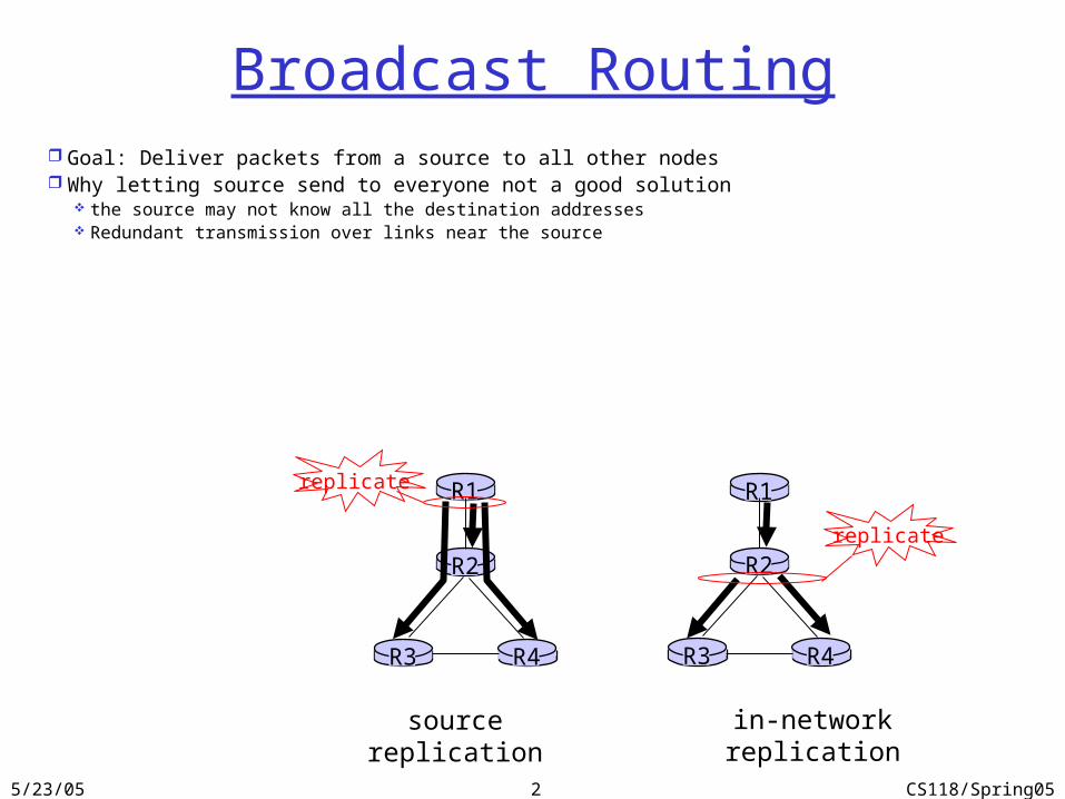
Broadcast Routing Goal: Deliver packets from a source to all other nodes Why letting source send to everyone not a good solution
the source may not know all the destination addresses Redundant transmission over links near the source
5/23/05 CS118/Spring053
In-network replication Flooding: when a node receives a broadcast packet, sends a
copy to all neighbors Problems: packet looping
Controlled flooding: node broadcast a packet if it hasn’t seen the same packet before Node must keep track of packet ids already seen
Reverse Path Forwarding (RPF): a node N forwards packet if it arrived on shortest path between N and source Make use of forwarding table of unicast routing
R1
R2
R3
R4
R5R6
R7
source
5/23/05 CS118/Spring054
A
B
G
DE
c
F
A
B
G
DE
c
F
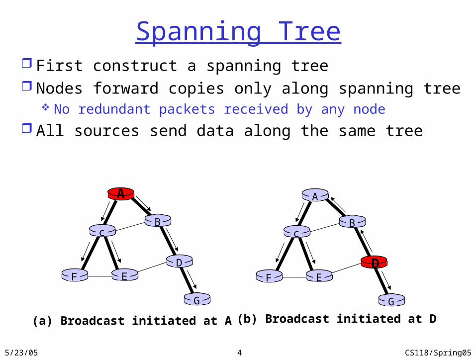
(a) Broadcast initiated at A (b) Broadcast initiated at D
Spanning Tree First construct a spanning tree Nodes forward copies only along spanning tree
No redundant packets received by any node
All sources send data along the same tree
5/23/05 CS118/Spring055
A
B
G
DE
c
F
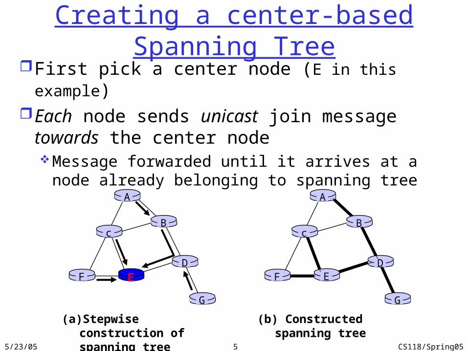
(a) Stepwise construction of spanning tree
A
B
G
DE
c
F
(b) Constructed spanning tree
Creating a center-based Spanning TreeFirst pick a center node (E in this example)Each node sends unicast join message towards
the center nodeMessage forwarded until it arrives at a node already
belonging to spanning tree
5/23/05 CS118/Spring056
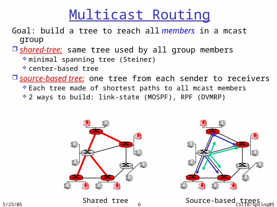
Multicast RoutingGoal: build a tree to reach all members in a mcast group shared-tree: same tree used by all group members
minimal spanning tree (Steiner) center-based tree
source-based tree: one tree from each sender to receivers Each tree made of shortest paths to all mcast members 2 ways to build: link-state (MOSPF), RPF (DVMRP)
Shared tree Source-based trees

5/23/05 CS118/Spring057
Shared-Tree: Steiner Tree
Steiner Tree: minimum cost tree connecting all routers with attached group members
problem is NP-completeexcellent heuristics existsnot used in practice:
computational complexity Infeasible to get/keep information about entire
networkmonolithic: rerun whenever a router needs to
join/leave
5/23/05 CS118/Spring058
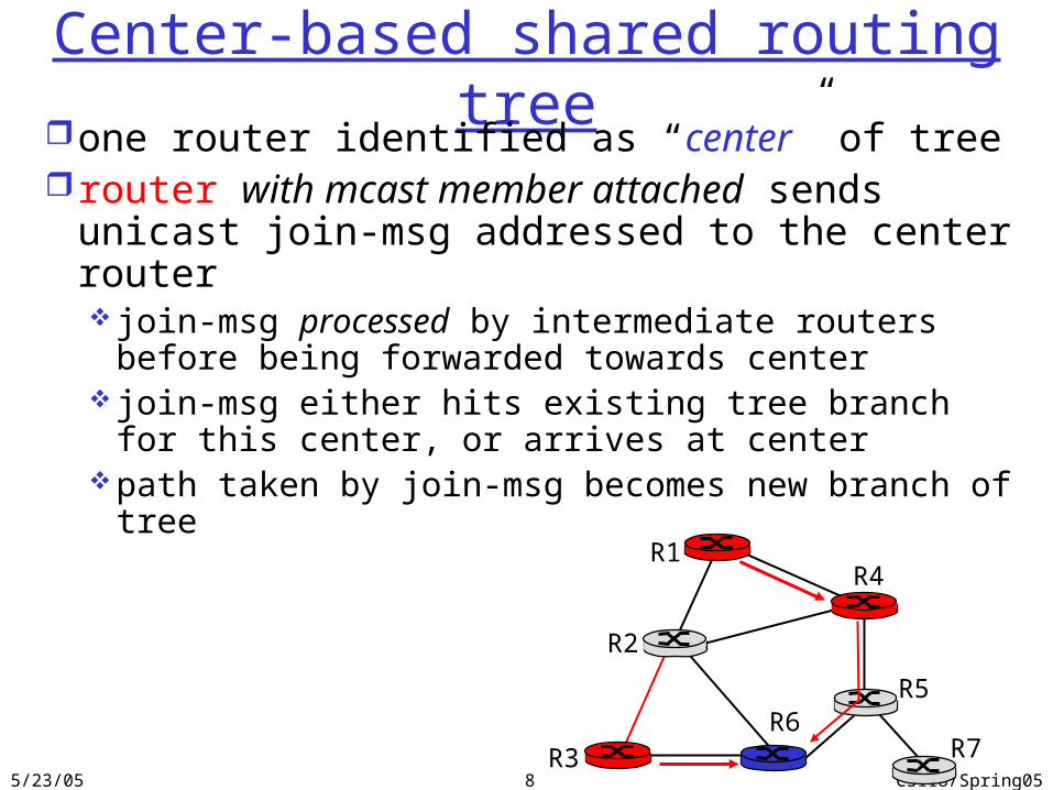
Center-based shared routing treeone router identified as “center” of treerouter with mcast member attached sends unicast
join-msg addressed to the center router join-msg processed by intermediate routers before
being forwarded towards center join-msg either hits existing tree branch for this
center, or arrives at centerpath taken by join-msg becomes new branch of tree
R1
R2
R3
R4
R5R6
R7
5/23/05 CS118/Spring059
R1
R2
R3
R4
R5
R6R7
router with attachedgroup member
router with no attachedgroup member
LEGEND
S: source
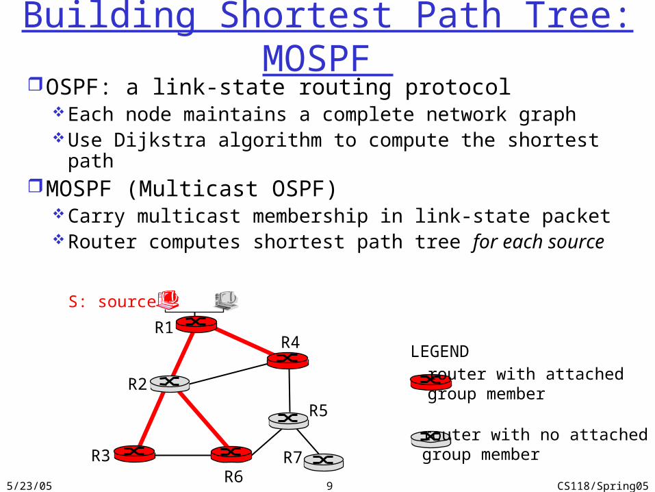
Building Shortest Path Tree: MOSPF OSPF: a link-state routing protocol
Each node maintains a complete network graph Use Dijkstra algorithm to compute the shortest path
MOSPF (Multicast OSPF)Carry multicast membership in link-state packetRouter computes shortest path tree for each source
5/23/05 CS118/Spring0510
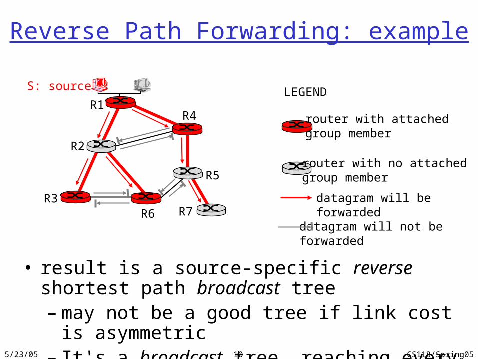
Reverse Path Forwarding: example
• result is a source-specific reverse shortest path broadcast tree– may not be a good tree if link cost is asymmetric– It's a broadcast tree, reaching every node
R1
R2
R3
R4
R5
R6 R7
router with attachedgroup member
router with no attachedgroup member
datagram will be forwarded
LEGENDS: source
datagram will not be forwarded
5/23/05 CS118/Spring0511
R1
R2
R3
R4
R5
R6 R7
router with attachedgroup member
router with no attachedgroup member
prune message
LEGENDS: source
links with multicastforwarding
P
P
P
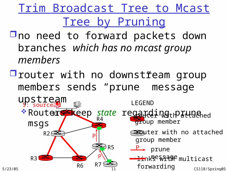
Trim Broadcast Tree to Mcast Tree by Pruning
no need to forward packets down branches which has no mcast group members
router with no downstream group members sends “prune” message upstreamRouters keep state regarding prune msgs
5/23/05 CS118/Spring0512
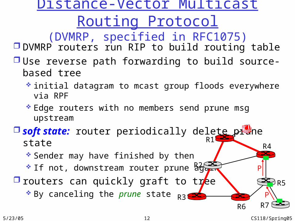
Distance-Vector Multicast Routing Protocol(DVMRP, specified in RFC1075)
DVMRP routers run RIP to build routing table Use reverse path forwarding to build source-based tree
initial datagram to mcast group floods everywhere via RPF Edge routers with no members send prune msg upstream
soft state: router periodically delete prune state Sender may have finished by then If not, downstream router prune again
routers can quickly graft to tree By canceling the prune state
R1
R2
R3
R4
R5
R6 R7
P
P
5/23/05 CS118/Spring0513
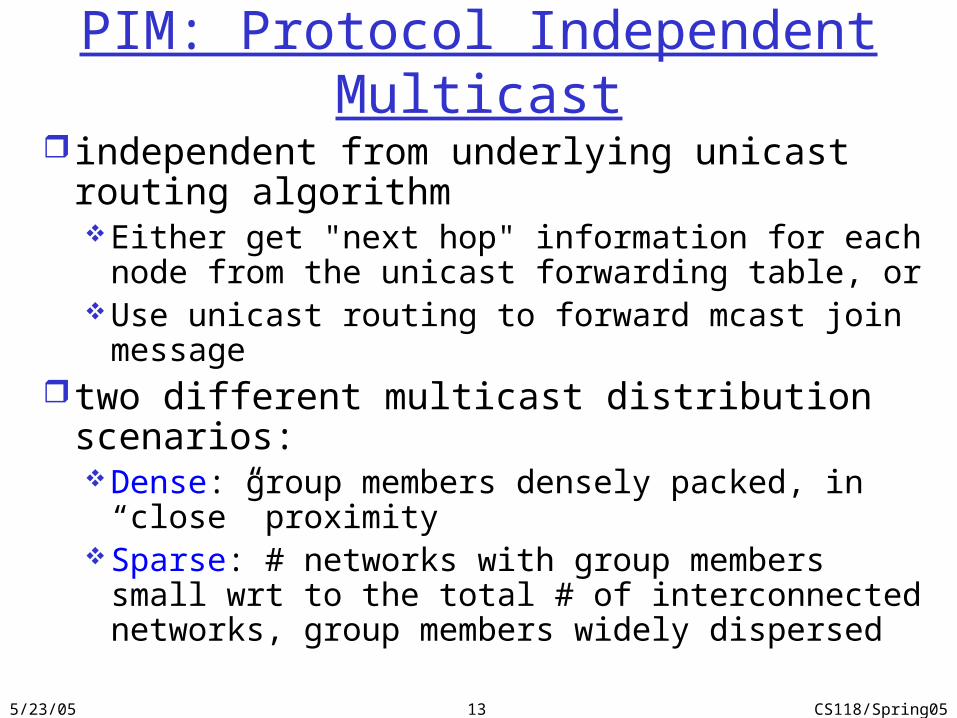
PIM: Protocol Independent Multicast
independent from underlying unicast routing algorithmEither get "next hop" information for each node from
the unicast forwarding table, orUse unicast routing to forward mcast join message
two different multicast distribution scenarios:Dense: group members densely packed, in “close”
proximity Sparse: # networks with group members small wrt to
the total # of interconnected networks, group members widely dispersed
5/23/05 CS118/Spring0514
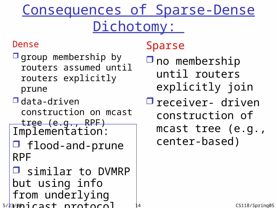
Consequences of Sparse-Dense Dichotomy:
Dense group membership by
routers assumed until routers explicitly prune
data-driven construction on mcast tree (e.g., RPF)
Sparse no membership until
routers explicitly join receiver- driven
construction of mcast tree (e.g., center-based)
Implementation: flood-and-prune RPF similar to DVMRP but using info from underlying unicast protocol for RPF checking

5/23/05 CS118/Spring0515
PIM - Sparse Mode Build center-based shared tree router sends join msg to
rendezvous point (RP) intermediate routers update state
and forward join msgs
Data sources: unicast packets to RP, which
forwards down RP-rooted tree
RP can send stop msg to source if no receivers joined the group “no one is listening!”
R1
R2
R3
R4
R5
R6R7
join
join
join
all data multicastfrom rendezvouspoint
rendezvouspoint
5/23/05 CS118/Spring0516
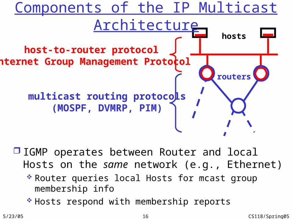
hosts
routers
host-to-router protocol Internet Group Management Protocol
multicast routing protocols(MOSPF, DVMRP, PIM)
Components of the IP Multicast Architecture
IGMP operates between Router and local Hosts on the same network (e.g., Ethernet) Router queries local Hosts for mcast group membership info Hosts respond with membership reports
5/23/05 CS118/Spring0517
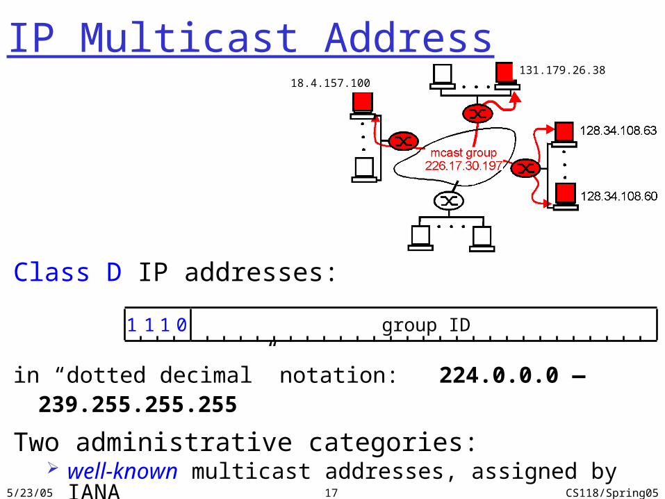
IP Multicast Address
Class D IP addresses:
in “dotted decimal” notation: 224.0.0.0 — 239.255.255.255
Two administrative categories: well-known multicast addresses, assigned by IANA (the rest) transient addresses, assigned & reclaimed dynamically
1 1 1 0 group ID
131.179.26.3818.4.157.100
5/23/05 CS118/Spring0518
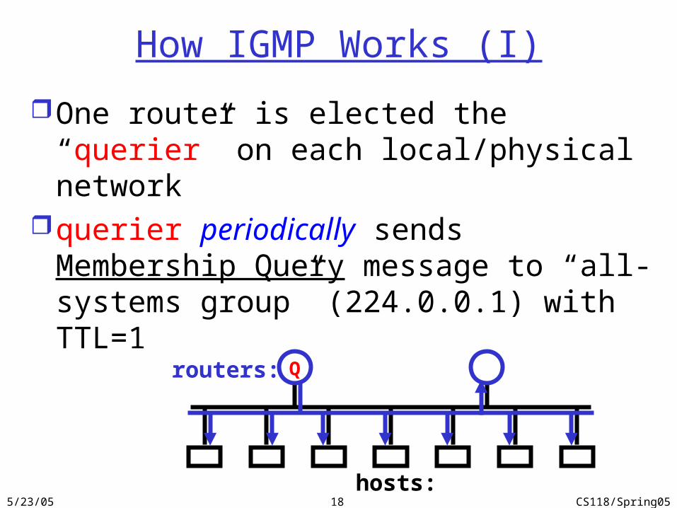
How IGMP Works (I)
One router is elected the “querier” on each local/physical network
querier periodically sends Membership Query message to “all-systems group” (224.0.0.1) with TTL=1
Qrouters:
hosts:
5/23/05 CS118/Spring0519
Q
G G G G
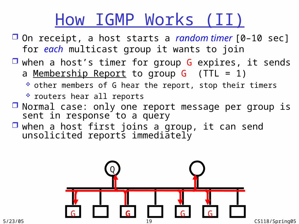
How IGMP Works (II) On receipt, a host starts a random timer [0–10 sec] for each
multicast group it wants to join when a host’s timer for group G expires, it sends a Membership
Report to group G (TTL = 1) other members of G hear the report, stop their timers routers hear all reports
Normal case: only one report message per group is sent in response to a query
when a host first joins a group, it can send unsolicited reports immediately
5/23/05 CS118/Spring0520
Q
G G G G
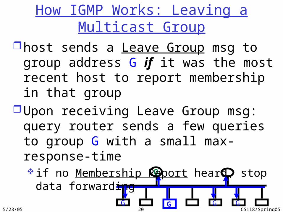
How IGMP Works: Leaving a Multicast Group
host sends a Leave Group msg to group address G if it was the most recent host to report membership in that group
Upon receiving Leave Group msg: query router sends a few queries to group G with a small max-response-time if no Membership Report heard, stop data forwarding
5/23/05 CS118/Spring0521
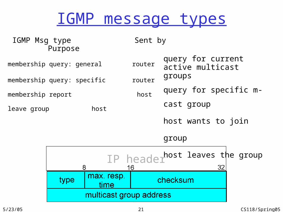
IGMP message types IGMP Msg type Sent by Purpose
membership query: general router
membership query: specific router
membership report host
leave group host
query for current active multicast groups
query for specific m-cast group
host wants to join group
host leaves the group
IP header
5/23/05 CS118/Spring0522
applicationtransportnetwork
linkphysical
networklink
physical
M
M
M
M
Ht
HtHn
HtHnHl MHtHnHl
framephys. link
data linkprotocol
adapter card
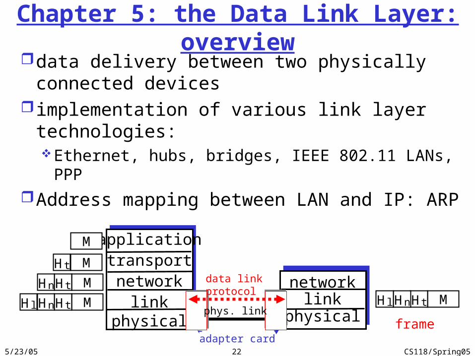
Chapter 5: the Data Link Layer: overviewdata delivery between two physically connected
devices implementation of various link layer
technologies:Ethernet, hubs, bridges, IEEE 802.11 LANs, PPP
Address mapping between LAN and IP: ARP
5/23/05 CS118/Spring0523
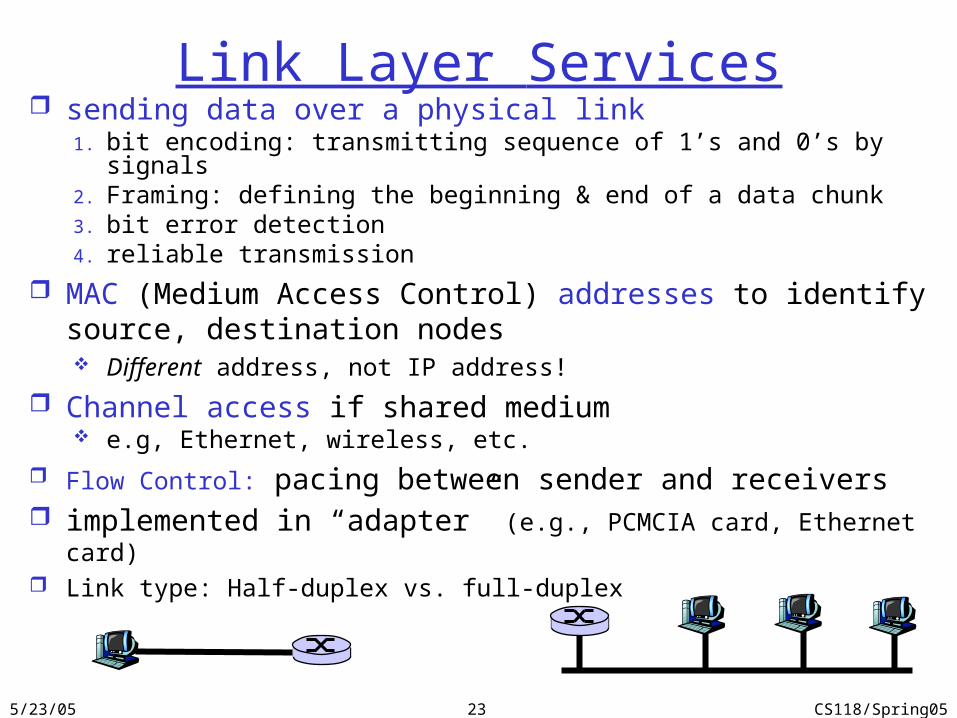
Link Layer Services sending data over a physical link
1. bit encoding: transmitting sequence of 1’s and 0’s by signals2. Framing: defining the beginning & end of a data chunk3. bit error detection4. reliable transmission
MAC (Medium Access Control) addresses to identify source, destination nodes Different address, not IP address!
Channel access if shared medium e.g, Ethernet, wireless, etc.
Flow Control: pacing between sender and receivers implemented in “adapter” (e.g., PCMCIA card, Ethernet card) Link type: Half-duplex vs. full-duplex
5/23/05 CS118/Spring0524
data
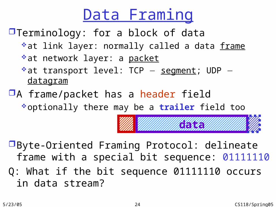
Data FramingTerminology: for a block of data
at link layer: normally called a data frameat network layer: a packetat transport level: TCP segment; UDP datagram
A frame/packet has a header fieldoptionally there may be a trailer field too
Byte-Oriented Framing Protocol: delineate frame with a special bit sequence: 01111110
Q: What if the bit sequence 01111110 occurs in data stream?
5/23/05 CS118/Spring0525
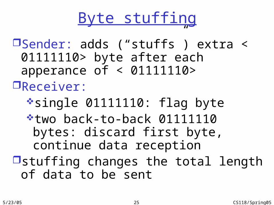
Byte stuffing
Sender: adds (“stuffs”) extra < 01111110> byte after each apperance of < 01111110>
Receiver: single 01111110: flag byte two back-to-back 01111110 bytes: discard first
byte, continue data receptionstuffing changes the total length of data to be sent
5/23/05 CS118/Spring0526
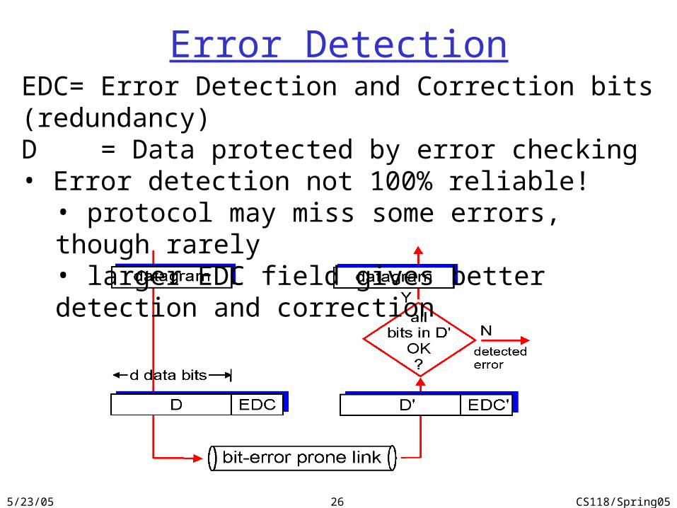
Error DetectionEDC= Error Detection and Correction bits (redundancy)D = Data protected by error checking• Error detection not 100% reliable!
• protocol may miss some errors, though rarely• larger EDC field gives better detection and correction
5/23/05 CS118/Spring0527
Parity Checking
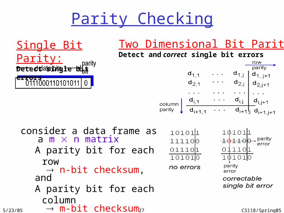
Single Bit Parity:Detect single bit errors
Two Dimensional Bit Parity:Detect and correct single bit errors
consider a data frame as a m n matrix
A parity bit for each row n-bit checksum,andA parity bit for each column m-bit checksum

5/23/05 CS118/Spring0528
Cyclic Redundancy Check (CRC)consider a data frame as a bit sequence M(x)
e.g. 10011010 M(x) = x7 + x4 + x3 + x1k-term polynomial has a degree of (k-1)
• e.g. 10011010 represents a 8-term polynomialuse a (r+1)-bit generator polynomial G(x) to
compute the checksum for M(x)sender makes the transmitted bit sequence dividable by
G(x) by appending r-bit remainder to M(x)receiver divides the received sequence by G(x)
M
M

5/23/05 CS118/Spring0529
How to compute CRC1. append r zero bits to M(x) to get xrM(x)
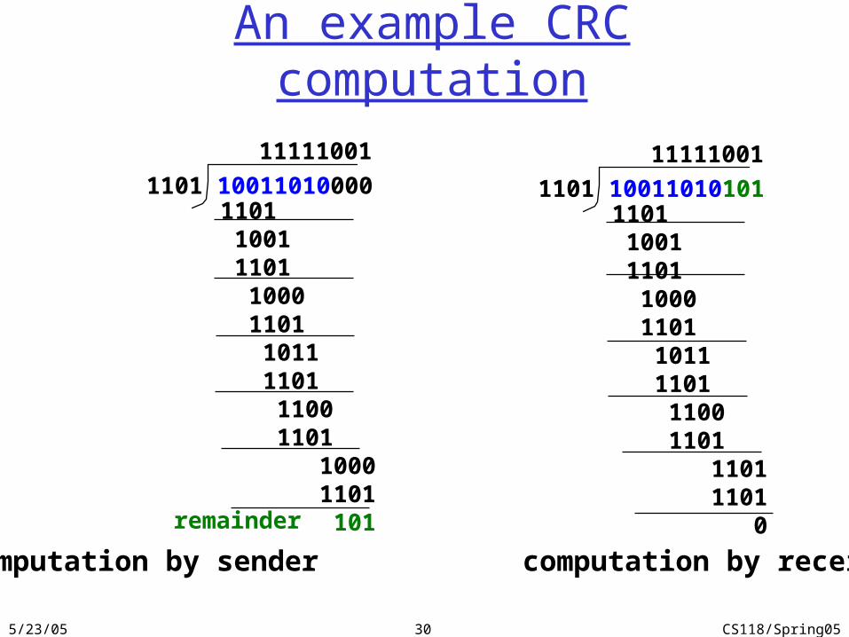
M(x) = 10011010 = x7 + x4 + x3 + x1, G(x) = 1101=x3 + x2 + 1, r = 3
then xrM(x) = x10 + x7 + x6 + x4 10011010000
2. divide xrM(x) by G(x)10011010000 / 1101 = 11111001, remainder 101
3. subtract the remainder from xrM(x) T(x), check-summed frame to be transmitted
xrM(x) / G(x) = Q(x), remainder R(x), T(x) = xrM(x) - R(x)In reality: just append R(x) to the end of data frame M(x) : 10011010 101Because: xrM(x) = shifting M(x) to the left by r bits, andfor XOR: r bits of 0's – R(x) = R(x)
At receiving end: if the received frame P(x) divisible by G(x), P(x)/G(x) = 0, P(X) considered error free
5/23/05 CS118/Spring0530
An example CRC computation
1101 100110100001101 1001 1101 1000 1101 1011 1101 1100 1101 1000 1101 101remainder
11111001
computation by sender computation by receiver
1101 100110101011101 1001 1101 1000 1101 1011 1101 1100 1101 1101 1101 0
11111001
5/23/05 CS118/Spring0531
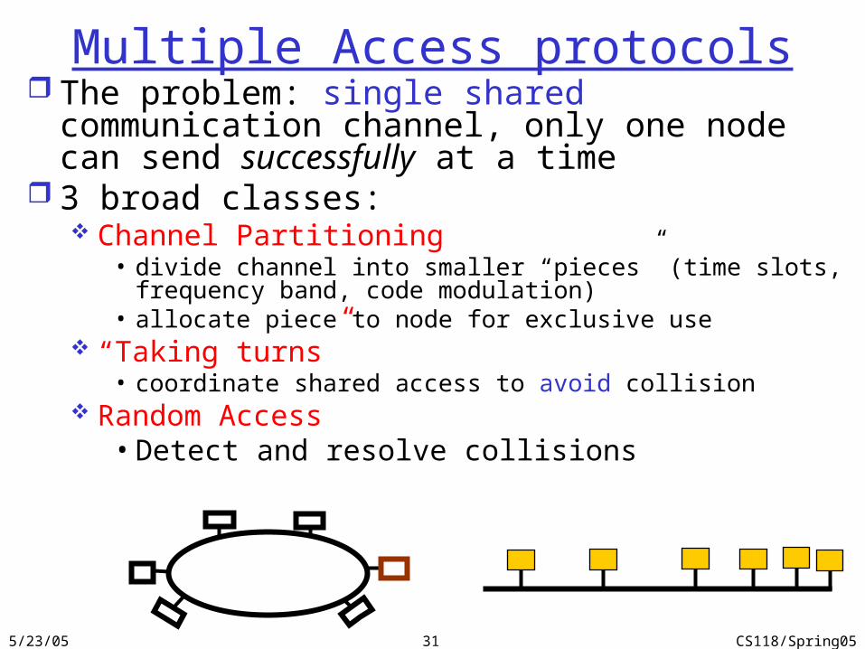
Multiple Access protocols The problem: single shared communication channel, only
one node can send successfully at a time 3 broad classes:
Channel Partitioning• divide channel into smaller “pieces” (time slots, frequency band, code
modulation)• allocate piece to node for exclusive use
“Taking turns”• coordinate shared access to avoid collision
Random Access• Detect and resolve collisions
5/23/05 CS118/Spring0532
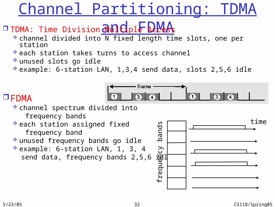
Channel Partitioning: TDMA and FDMA TDMA: Time Division Multiple Access
channel divided into N fixed length time slots, one per station each station takes turns to access channel unused slots go idle example: 6-station LAN, 1,3,4 send data, slots 2,5,6 idle
FDMA channel spectrum divided into frequency bands each station assigned fixed frequency band unused frequency bands go idle example: 6-station LAN, 1, 3, 4 send data, frequency bands 2,5,6 idle
frequ
ency
bands time
5/23/05 CS118/Spring0533
“Taking Turns” MAC protocols channel partitioning: commonalities
Share channel efficiently with constant, uniform loadBut inefficient with random, non-uniform load
• delay in channel access
• 1/N bandwidth allocated even if only 1 active node!
“taking turns” protocols: on-demand channel allocationPolling: master node asks slave nodes to transmit in turn
• Concerns: polling latency, single point of failure
Token passing
5/23/05 CS118/Spring0534
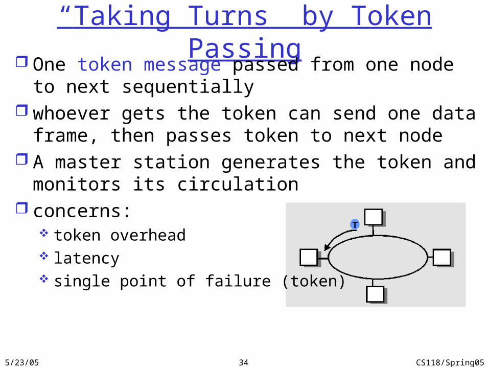
“Taking Turns” by Token Passing One token message passed from one node to next
sequentially whoever gets the token can send one data frame, then
passes token to next node A master station generates the token and monitors its
circulation concerns:
token overhead latency single point of failure (token)
5/23/05 CS118/Spring0535
Random Access protocols When node has packet to send
transmit at full channel data rate R. no a priori coordination among nodes
If two or more nodes transmitting at the same time “collision”
random access MAC protocol specifies: how to detect collisions how to recover from collisions
Examples of random access MAC protocols: ALOHA slotted ALOHA CSMA and CSMA/CD
5/23/05 CS118/Spring0536
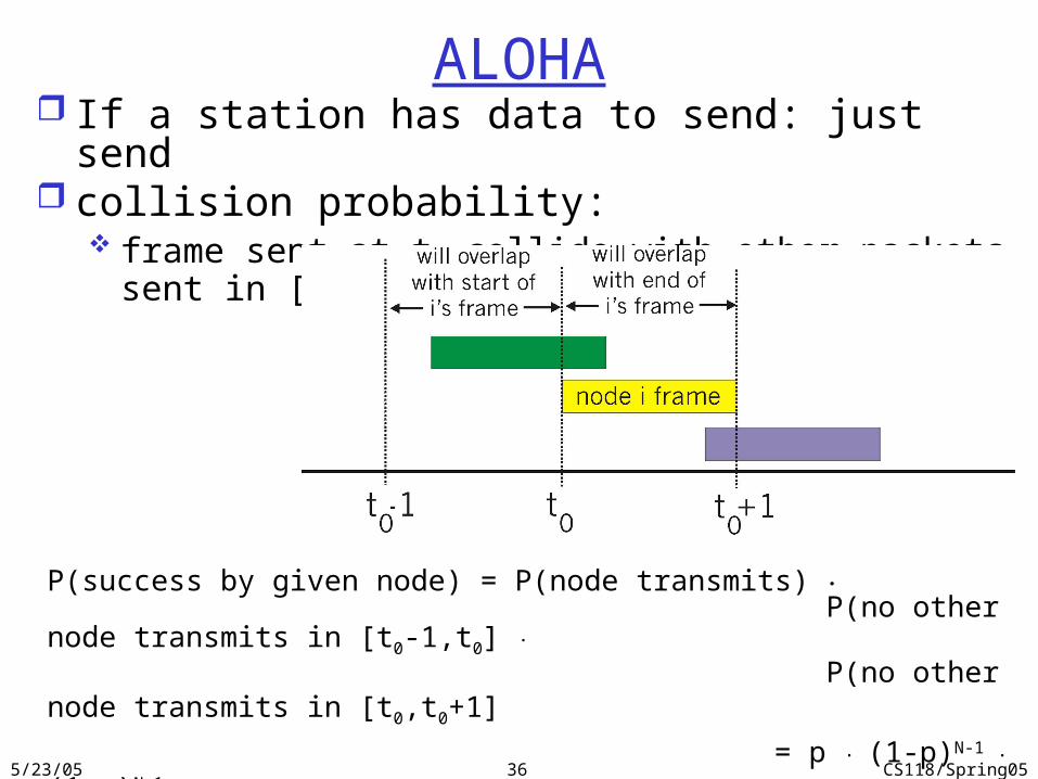
ALOHA If a station has data to send: just send collision probability:
frame sent at t0 collide with other packets sent in [t0-1, t0+1]
P(success by given node) = P(node transmits) . P(no other node transmits in [t0-1,t0] .
P(no other node transmits in [t0,t0+1]
= p . (1-p)N-1 . (1-p)N-1
P(success by any node) = N p . (1-p) 2(N-1) choosing optimum p as n ∞ ...
= 1/(2e) = 0.18
5/23/05 CS118/Spring0537
Slotted Aloha
Assumptions:All frames the same size; clocks in all nodes are
synchronizedDivide time into equal size slots (= pkt trans.
time)If 2 or more nodes transmit in the same slot, all
nodes detect collision
5/23/05 CS118/Spring0538
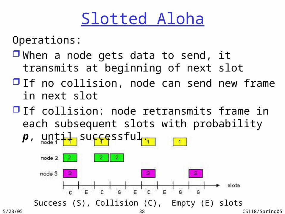
Success (S), Collision (C), Empty (E) slots
Slotted AlohaOperations: When a node gets data to send, it transmits at beginning
of next slot If no collision, node can send new frame in next slot If collision: node retransmits frame in each subsequent
slots with probability p, until successful.
5/23/05 CS118/Spring0539
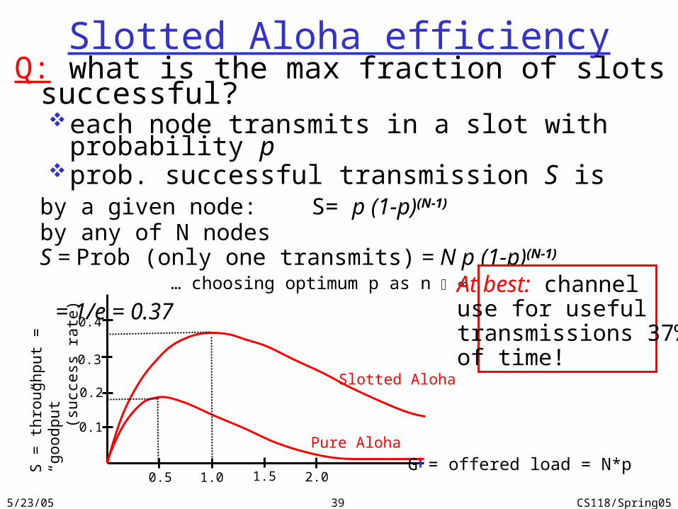
Slotted Aloha efficiencyQ: what is the max fraction of slots successful?
each node transmits in a slot with probability pprob. successful transmission S is
by a given node: S= p (1-p)(N-1)
by any of N nodes S = Prob (only one transmits) = N p (1-p)(N-1)
… choosing optimum p as n ∞ ...
= 1/e = 0.37At best: channeluse for useful transmissions 37%of time!
S =
thro
ughput
=
“goodput”
(
succ
ess
rate
)
G = offered load = N*p0.5 1.0 1.5 2.0
0.1
0.2
0.3
0.4
Pure Aloha
Slotted Aloha
5/23/05 CS118/Spring0540
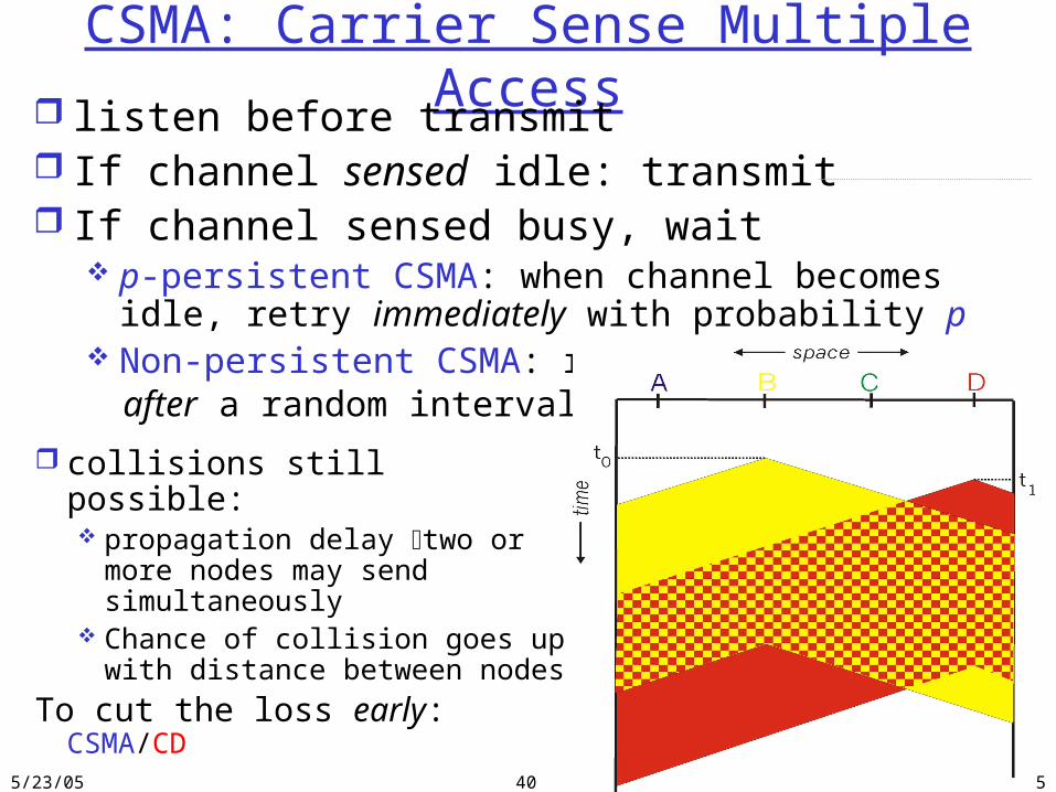
CSMA: Carrier Sense Multiple Access listen before transmit If channel sensed idle: transmit If channel sensed busy, wait
p-persistent CSMA: when channel becomes idle, retry immediately with probability p
Non-persistent CSMA: retry after a random interval
collisions still possible: propagation delay two or more
nodes may send simultaneously Chance of collision goes up
with distance between nodes
To cut the loss early: CSMA/CD
5/23/05 CS118/Spring0541
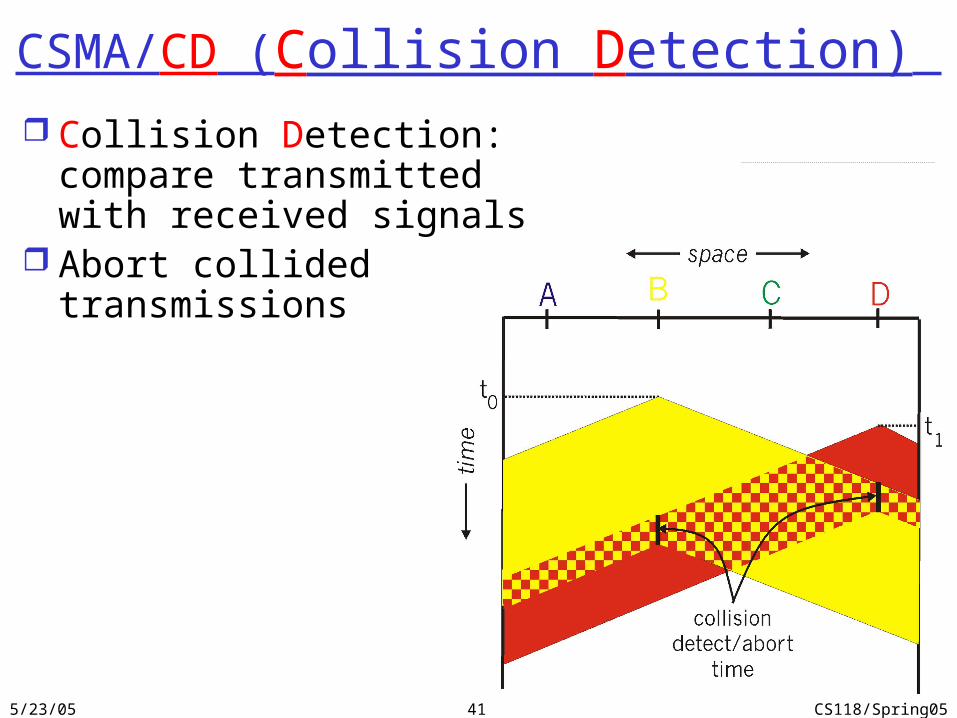
CSMA/CD (Collision Detection) Collision Detection: compare
transmitted with received signals Abort collided transmissions
5/23/05 CS118/Spring0542
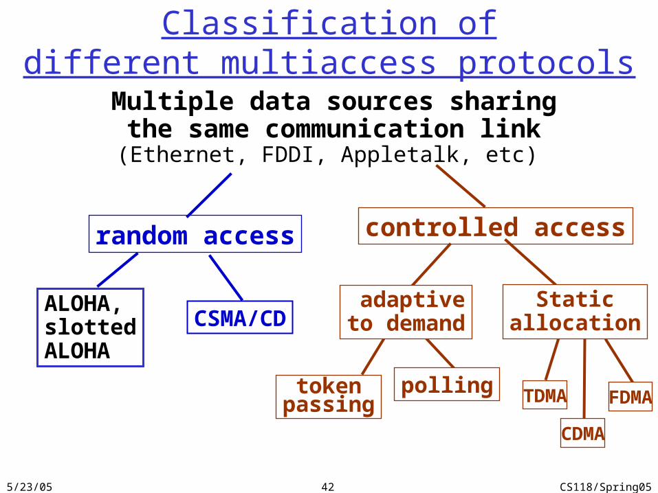
random access
ALOHA,slottedALOHA
CSMA/CD
Classification ofdifferent multiaccess protocols
Multiple data sources sharingthe same communication link
(Ethernet, FDDI, Appletalk, etc)
tokenpassing TDMApolling
Staticallocation
controlled access
adaptiveto demand
FDMA
CDMA
5/23/05 CS118/Spring0543
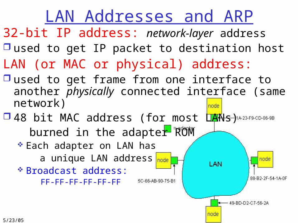
LAN Addresses and ARP32-bit IP address: network-layer address used to get IP packet to destination host
LAN (or MAC or physical) address: used to get frame from one interface to another physically
connected interface (same network) 48 bit MAC address (for most LANs) burned in the adapter ROM
Each adapter on LAN has a unique LAN address Broadcast address: FF-FF-FF-FF-FF-FF
5/23/05 CS118/Spring0544
LAN Address (more)
MAC address allocation administered by IEEE manufacturer buys portion of MAC address space (to
assure uniqueness) Analogy: (a) MAC address: like Social Security Number (b) IP address: like postal address MAC flat address => portability
can move LAN card from one LAN to another IP hierarchical address NOT portable
depends on network to which one attaches
5/23/05 CS118/Spring0545
Recall earlier routing discussion
223.1.1.1
223.1.1.2
223.1.1.3
223.1.1.4 223.1.2.9
223.1.2.2
223.1.2.1
223.1.3.2223.1.3.1
223.1.3.27
A
BE
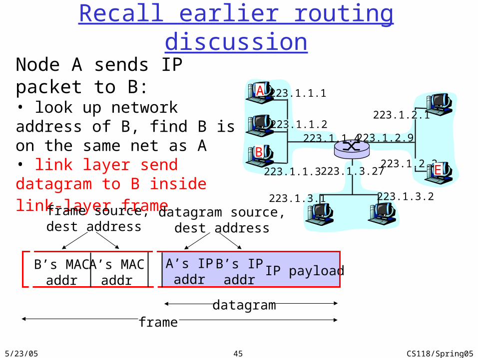
Node A sends IP packet to B:• look up network address of B, find B is on the same net as A• link layer send datagram to B inside link-layer frame
B’s MACaddr
A’s MACaddr
A’s IPaddr
B’s IPaddr
IP payload
datagramframe
frame source,dest address
datagram source,dest address
5/23/05 CS118/Spring0546
ARP: Address Resolution Protocol
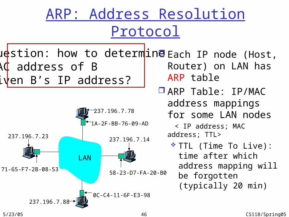
Each IP node (Host, Router) on LAN has ARP table
ARP Table: IP/MAC address mappings for some LAN nodes
< IP address; MAC address; TTL>
TTL (Time To Live): time after which address mapping will be forgotten (typically 20 min)
Question: how to determineMAC address of Bgiven B’s IP address?
1A-2F-BB-76-09-AD
58-23-D7-FA-20-B0
0C-C4-11-6F-E3-98
71-65-F7-2B-08-53
LAN
237.196.7.23
237.196.7.78
237.196.7.14
237.196.7.88
5/23/05 CS118/Spring0547
ARP protocol A knows B's IP address, wants to learn B's MAC address A broadcasts ARP query pkt, containing B's IP address
Dest MAC address = FF-FF-FF-FF-FF-FF all machines on LAN receive ARP query
B receives ARP packet, replies to A with its (B's) physical layer address reply sent to A’s MAC address (unicast)
A caches (saves) IP-to-physical address pairs until information becomes old (times out) soft state: information that times out (goes away) unless refreshed
ARP is “plug-and-play”: nodes create their ARP tables without intervention from net
administrator
5/23/05 CS118/Spring0548
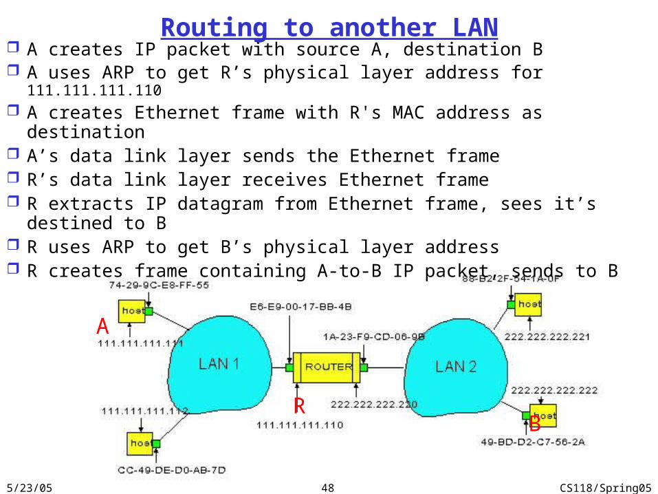
A creates IP packet with source A, destination B A uses ARP to get R’s physical layer address for 111.111.111.110 A creates Ethernet frame with R's MAC address as destination A’s data link layer sends the Ethernet frame R’s data link layer receives Ethernet frame R extracts IP datagram from Ethernet frame, sees it’s destined to B R uses ARP to get B’s physical layer address R creates frame containing A-to-B IP packet, sends to B
A
RB
Routing to another LAN
5/23/05 CS118/Spring0549
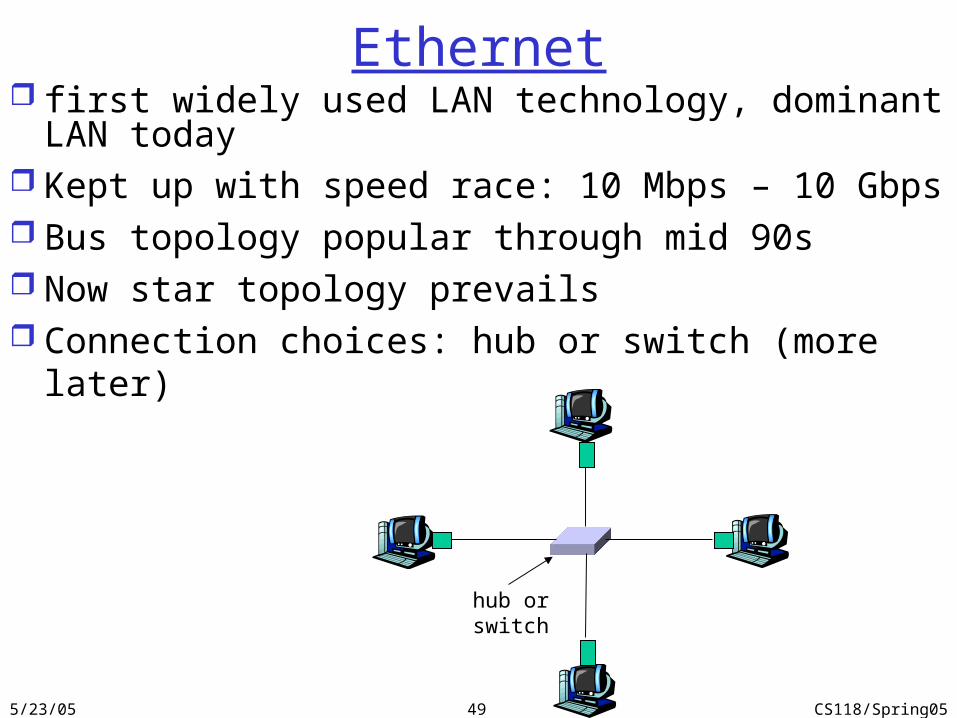
Ethernet first widely used LAN technology, dominant LAN today Kept up with speed race: 10 Mbps – 10 Gbps Bus topology popular through mid 90s Now star topology prevails Connection choices: hub or switch (more later)
hub orswitch
5/23/05 CS118/Spring0550
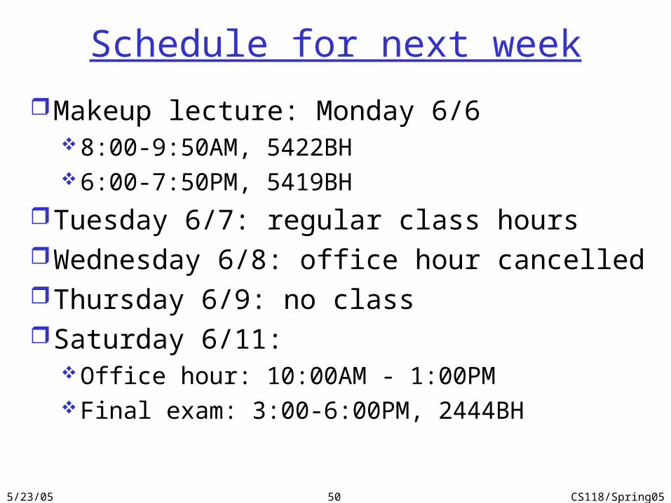
Schedule for next week
Makeup lecture: Monday 6/68:00-9:50AM, 5422BH6:00-7:50PM, 5419BH
Tuesday 6/7: regular class hoursWednesday 6/8: office hour cancelledThursday 6/9: no classSaturday 6/11:
Office hour: 10:00AM - 1:00PMFinal exam: 3:00-6:00PM, 2444BH
5/23/05 CS118/Spring0551
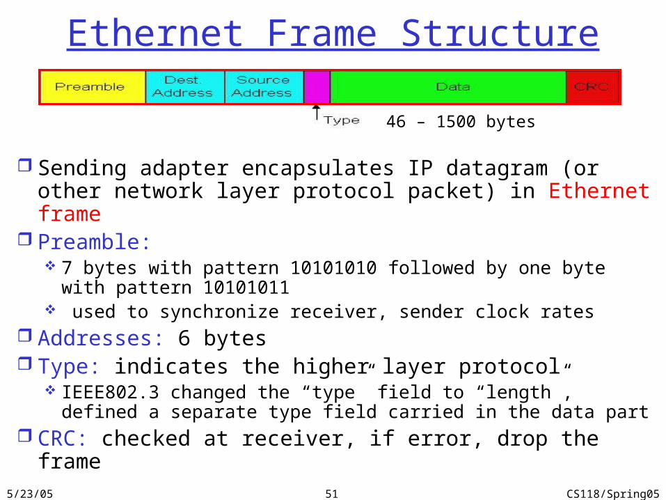
Ethernet Frame Structure
Sending adapter encapsulates IP datagram (or other network layer protocol packet) in Ethernet frame
Preamble: 7 bytes with pattern 10101010 followed by one byte with pattern
10101011 used to synchronize receiver, sender clock rates
Addresses: 6 bytes Type: indicates the higher layer protocol
IEEE802.3 changed the “type” field to “length”, defined a separate type field carried in the data part
CRC: checked at receiver, if error, drop the frame
46 – 1500 bytes
5/23/05 CS118/Spring0552
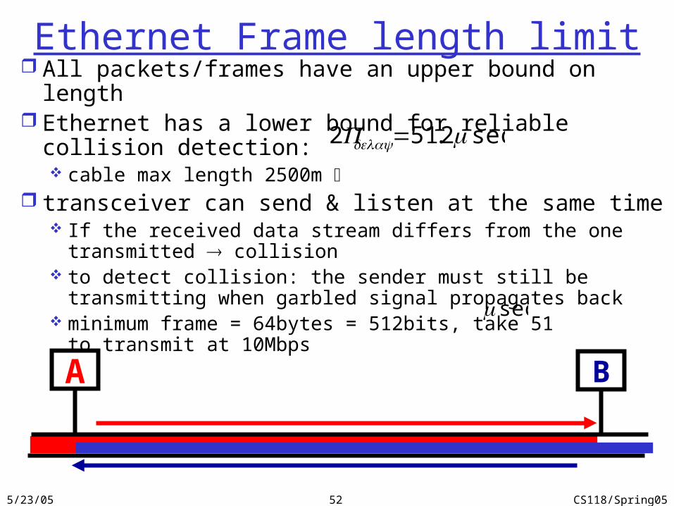
Ethernet Frame length limit All packets/frames have an upper bound on length Ethernet has a lower bound for reliable collision detection:
cable max length 2500m transceiver can send & listen at the same time
If the received data stream differs from the one transmitted collision
to detect collision: the sender must still be transmitting when garbled signal propagates back
minimum frame = 64bytes = 512bits, take 51 to transmit at 10Mbps
sec2.512 μ=delayP
secμ
BA
5/23/05 CS118/Spring0553
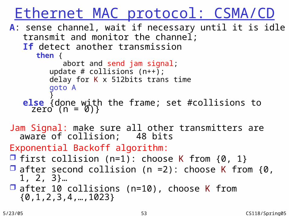
Ethernet MAC protocol: CSMA/CDA: sense channel, wait if necessary until it is idle
transmit and monitor the channel; If detect another transmission
then { abort and send jam signal;
update # collisions (n++); delay for K x 512bits trans timegoto A}
else {done with the frame; set #collisions to zero (n = 0)}
Jam Signal: make sure all other transmitters are aware of collision; 48 bits
Exponential Backoff algorithm: first collision (n=1): choose K from {0, 1} after second collision (n =2): choose K from {0, 1, 2, 3}… after 10 collisions (n=10), choose K from {0,1,2,3,4,…,1023}
5/23/05 CS118/Spring0554
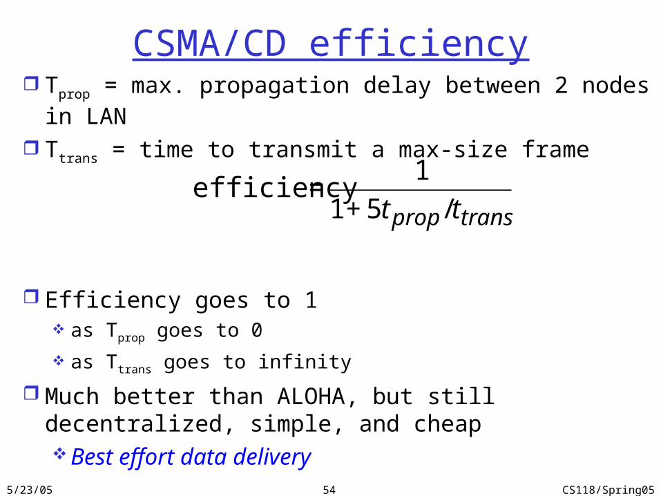
CSMA/CD efficiency Tprop = max. propagation delay between 2 nodes in LAN
Ttrans = time to transmit a max-size frame
Efficiency goes to 1 as Tprop goes to 0
as Ttrans goes to infinity
Much better than ALOHA, but still decentralized, simple, and cheapBest effort data delivery
€
efficiency =1
1+ 5t prop / ttrans
5/23/05 CS118/Spring0555
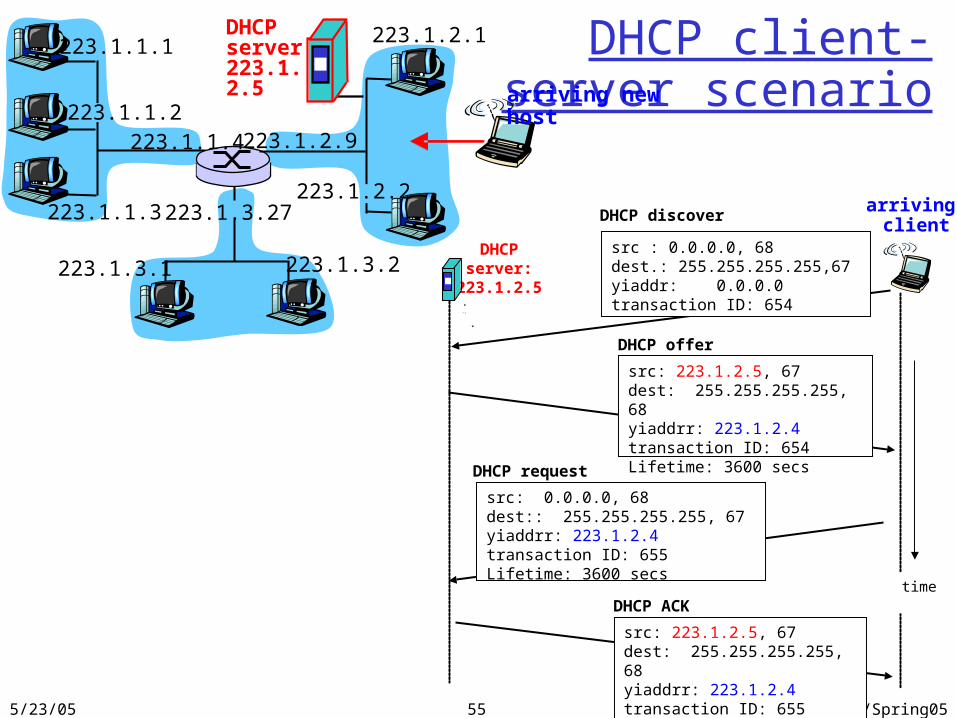
DHCP client-server scenario
223.1.1.1
223.1.1.2
223.1.1.3
223.1.1.4 223.1.2.9
223.1.2.2
223.1.2.1
223.1.3.2223.1.3.1
223.1.3.27
DHCP server 223.1.2.5
DHCP server:
223.1.2.5
arriving client
time
DHCP discover
src : 0.0.0.0, 68 dest.: 255.255.255.255,67yiaddr: 0.0.0.0transaction ID: 654
DHCP offer
src: 223.1.2.5, 67 dest: 255.255.255.255, 68yiaddrr: 223.1.2.4transaction ID: 654Lifetime: 3600 secs
DHCP request
src: 0.0.0.0, 68 dest:: 255.255.255.255, 67yiaddrr: 223.1.2.4transaction ID: 655Lifetime: 3600 secs
DHCP ACK
src: 223.1.2.5, 67 dest: 255.255.255.255, 68yiaddrr: 223.1.2.4transaction ID: 655Lifetime: 3600 secs
arriving new host
5/23/05 CS118/Spring0556
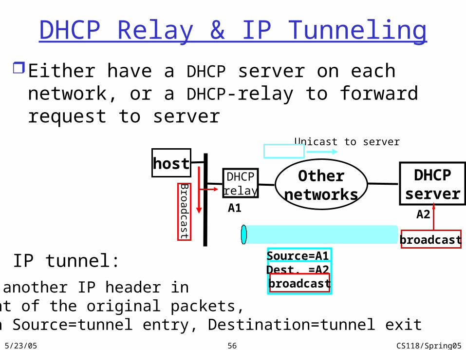
DHCPrelay
Broadcast
Othernetworks
DHCPserver
host
Unicast to server
Either have a DHCP server on each network, or a DHCP-relay to forward request to server
A1 A2
broadcastSource=A1Dest. =A2broadcast
DHCP Relay & IP Tunneling
Put another IP header infront of the original packets,with Source=tunnel entry, Destination=tunnel exit
IP tunnel:


![BU 2100 – en EtherNet/IP bus interface · 2020. 8. 25. · (1.) Einleitung/EtherNet IP [BU 2100]/Abkürzungsverzeichnis Ether. Net/IP @ 8\mod_1464866172454_388.docx @ 2252268 @](https://img.dokumen.tips/doc/110x75/60d61ff53035640c0c7e121d/bu-2100-a-en-ethernetip-bus-interface-2020-8-25-1-einleitungethernet.jpg)