Embed Size (px)
Citation preview
Introduction to Introduction to CommunicationsCommunications
SCHOOL ON RADIO USE FOR DIGITAL AND MULTIMEDIA
COMMUNICATIONS
ICTP, February 2002
Ermanno Pietrosemoli
Latin American Networking School
University of Los Andes
Merida- Venezuela
Introduction to CommunicationIntroduction to Communication
Transmission Basic Guided Media Non Guided Media Spectrum Utilization Strategies Access Techniques Evolution of Communications Communication Standards
Transmission MediaTransmission Media
All based in electromagnetic waves Transmission speed comparable with that of
light, c = 300 Mm/s Attenuation increases with distance Subjects to interference and Noise Limits on Bandwidth
Transmission MediaTransmission Media
Ideal Channel:
•Constant Attenuation
•Constant Delay

Transmission MediaTransmission Media
Real Channel:
•Variable Attenuation
(Amplitude Distorsion)
•Phase or delay Distorsion
Transmission MediaTransmission Media
Crosstalk
• NEXT
• FEXT
NEXT:NEXT: Near End Cross Talk Near End Cross Talk
Parasitic coupling of energy from one circuit to another
That originates in the same end
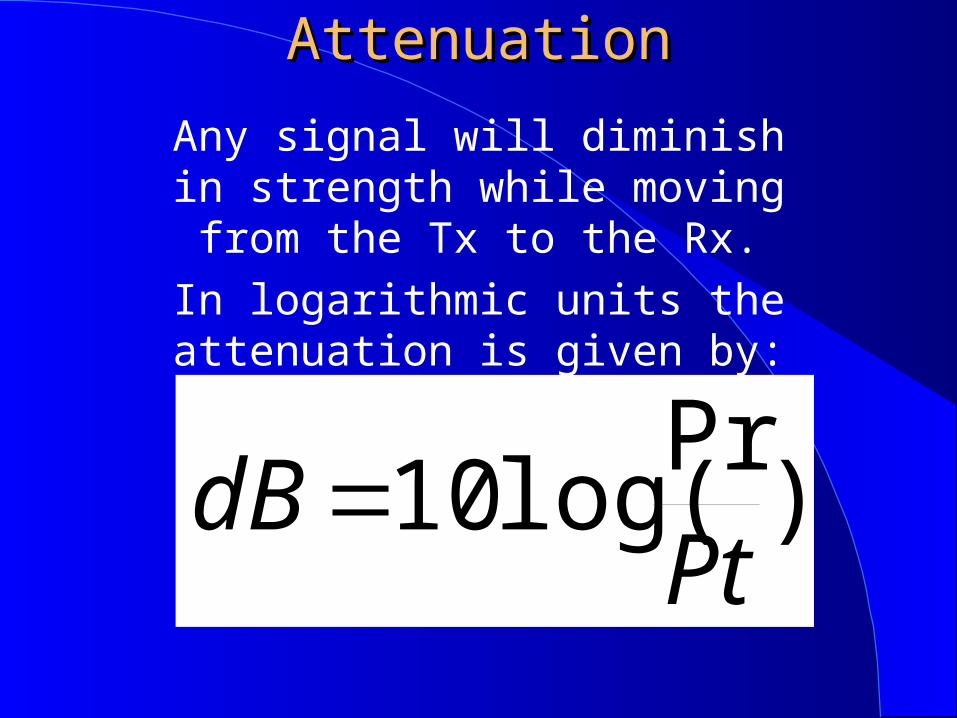
AttenuationAttenuation
Any signal will diminish in strength while moving from the Tx to the Rx.
In logarithmic units the attenuation is given by:
)Pr
log(10Pt
dB

Absolute PowerAbsolute PowerAbsolute Power can be expressed
logarithmically by comparing with a specified reference:
)1
Prlog(10
mWdBm

(mW) dBm
1 0
10 10
20 13
100 20
1000 30
0.5 -3
0.1 -10
0.01 -20
Power: mW or dBm

BandwidthBandwidth
• Transmission speed in bits/s is proportional to
bandwidth in Hz
• The factor depends on the modulation technique
employed (bandwidth efficiency)
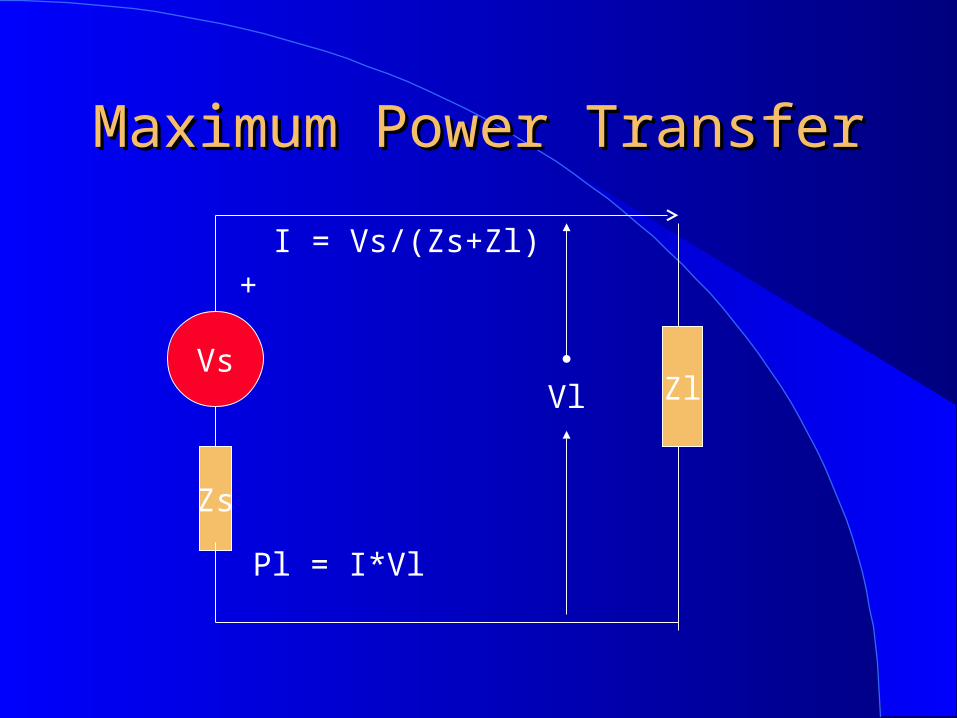
Maximum Power TransferMaximum Power Transfer
Vs
Zs
ZlVl
+
I = Vs/(Zs+Zl)
Pl = I*Vl
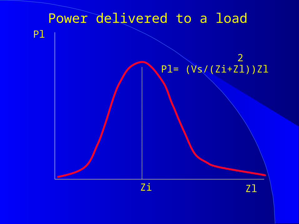
Pl
Zl
Power delivered to a load
Pl= (Vs/(Zi+Zl))Zl2
Zi
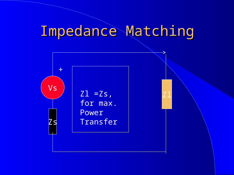
Impedance MatchingImpedance Matching
Vs
Zs
Zl
+
Zl =Zs, for max. PowerTransfer
Impedance MatchingImpedance Matching
Impedance Matching is measured by
VSWR (Voltage Standing Wave Ratio).
Ideally unit
When greater than 2, excessive reflected power.
Impedance MatchingImpedance Matching
Standing wave is measured by a Wattmeter.
VSWR= (Pi+Pr)/(Pi-Pr)

Fundamental ConceptsFundamental Concepts
Antennas physical dimension > /10 Transmission Bandwidth proportional to
carrier frequency B < fc/10
SignalSinusoidal Signal
0
+A
-A
t
Señal Sinusoidal (Coseno)
T)tf2cos(A)t(v o
Waveshapes and spectrum
Forma de Onda Espectro fc
f
(a) Señal Sinusoidal
0t
0
T
0 fo2fo 3fo 4fo
5fof
Forma de Onda
0 t
Espectro de Líneas (Discreto)
(b) Señal Periódica Rectangular (de Potencia)
0t
0f
Forma de Onda Espectro (Continuo)
(c) Señal Aperiódica (de Energía)
fo =1/T
B
Amplitud
Amplitud
Amplitud
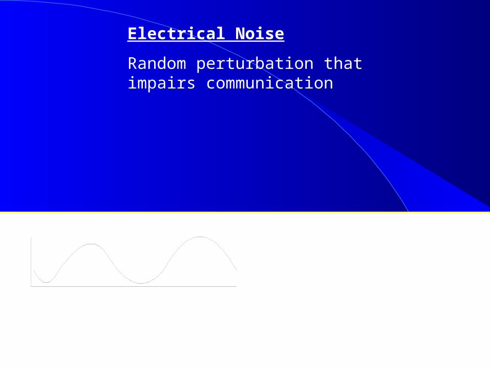
Electrical Noise
Random perturbation that impairs communication
(a) Señal sin Ruido (b) Señal con Ruido0 0t t
Fig. 1.7. Efecto del Ruido sobre una Señal.

Signals
Signal to Noise Ratio
S/N= (Average Signal Power)/(Noise Power)
In dB,
)N
S(log10 (dB)
N
S10
dB
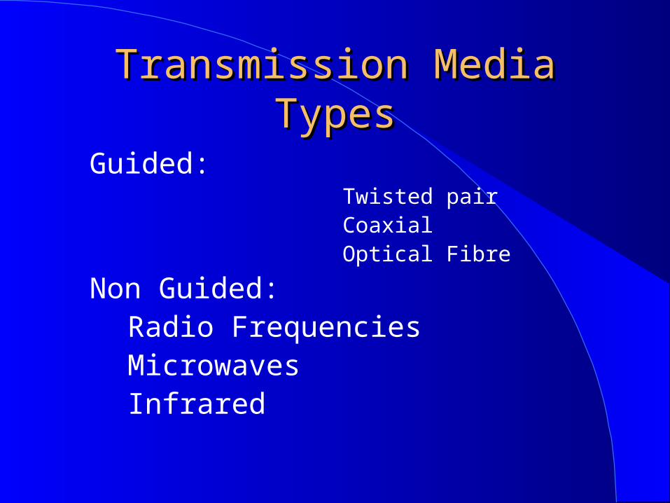
Transmission Media TypesTransmission Media Types
Guided: Twisted pair Coaxial Optical Fibre
Non Guided:Radio FrequenciesMicrowavesInfrared
How can one transmit a How can one transmit a signal?signal?
One conducting wire, ground return, cheap but greatly affected by interference and noise. Used in the early telegraphic systems, it was soon replaced by two parallel wires.
Two parallel wires, diminishes interference, but it is better if twisted, the more the twisting, the highest the frequency response

Guided MediaGuided MediaCoaxial Cable
Twisted Pair
cladddingCoating
buffering
Optical Fibre
core
Twisted PairTwisted Pair
Can be Shielded (STP) to further reduce interference, or Unshielded (UTP) for easier installation
Most cost effective for short distances Easy to install and terminate Can support up to 250 Mbps at short
distances
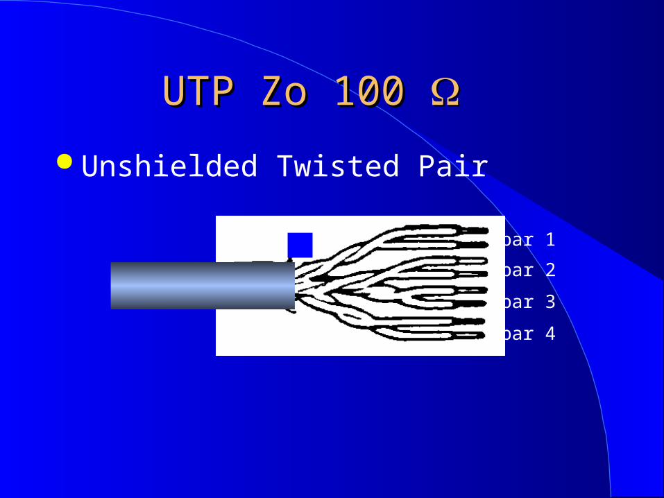
UTP Zo 100 UTP Zo 100
Unshielded Twisted Pair
par 1
par 2
par 3
par 4
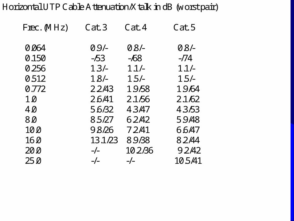
Horizontal UTP Cable Attenuation/Xtalk in dB (worst pair) Frec. (MHz) Cat. 3 Cat. 4 Cat. 5 0.064 0.9/- 0.8/- 0.8/- 0.150 -/53 -/68 -/74 0.256 1.3/- 1.1/- 1.1/- 0.512 1.8/- 1.5/- 1.5/- 0.772 2.2/43 1.9/58 1.9/64 1.0 2.6/41 2.1/56 2.1/62 4.0 5.6/32 4.3/47 4.3/53 8.0 8.5/27 6.2/42 5.9/48 10.0 9.8/26 7.2/41 6.6/47 16.0 13.1/23 8.9/38 8.2/44 20.0 -/- 10.2/36 9.2/42 25.0 -/- -/- 10.5/41

Cable FTP de 100 Cable FTP de 100
Foildeed Twisted Pair
par 1
par 2
par 3
par 4
Conducting wire preserves continity of shield
Shield
Coaxial CableCoaxial Cable
Inner conductor inside a flexible metallic cover, separated by a dielectric
External cover can be a mesh, and is always coated by a protective insulator.
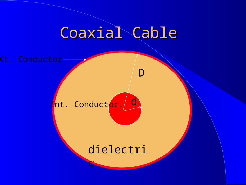
Coaxial Cable Coaxial Cable
d
D
d
dielectric
Xt. Conductor
Int. Conductor.
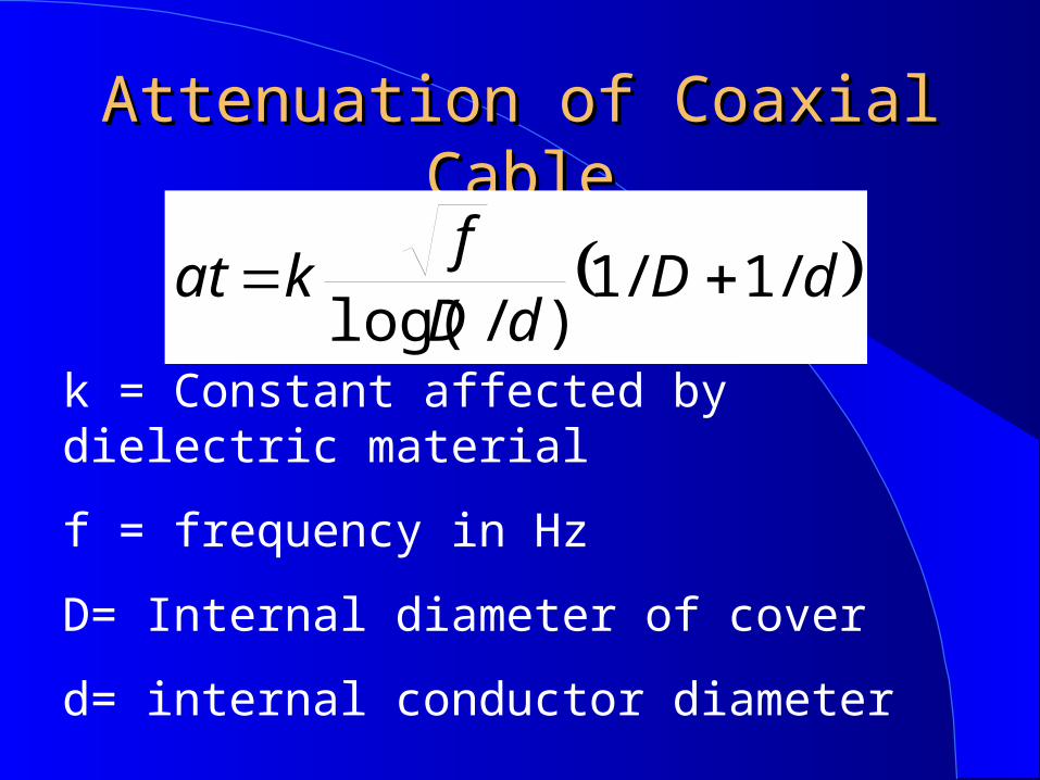
Attenuation of Coaxial CableAttenuation of Coaxial Cable
dDdD
fkat /1/1
)/log(
k = Constant affected by dielectric material
f = frequency in Hz
D= Internal diameter of cover
d= internal conductor diameter
Coaxial CableCoaxial Cable
Attenuation proportional to square root of frequency and inversely proportional to diameter.
The ratio between conductors diameters specifies characteristic impedance
Propagation speed between 0.7c and 0.9c

Coaxial CableCoaxial Cable
No longer recommended in local area networks, it is being substituted by UTP at short distances an Fibre at long distances
Still widely used in TV distribution and for connecting radios to antennas.
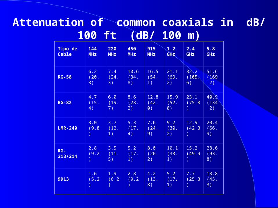
Attenuation of common coaxials in dB/ 100 ft (dB/ 100 m)
Tipo de Cable
144 MHz
220 MHz
450 MHz
915 MHz
1.2 GHz
2.4 GHz
5.8 GHz
RG-586.2 (20.3)
7.4(24.3)
10.6(34.8)
16.5(54.1)
21.1(69.2)
32.2(105.6)
51.6(169.2)
RG-8X4.7 (15.4)
6.0(19.7)
8.6(28.2)
12.8(42.0)
15.9(52.8)
23.1(75.8)
40.9(134.2)
LMR-2403.0 (9.8)
3.7(12.1)
5.3(17.4)
7.6(24.9)
9.2(30.2)
12.9(42.3)
20.4(66.9)
RG-213/2142.8 (9.2)
3.5(11.5)
5.2(17.1)
8.0(26.2)
10.1(33.1)
15.2(49.9)
28.6(93.8)
99131.6 (5.2)
1.9(6.2)
2.8(9.2)
4.2(13.8)
5.2(17.1)
7.7(25.3)
13.8(45.3)
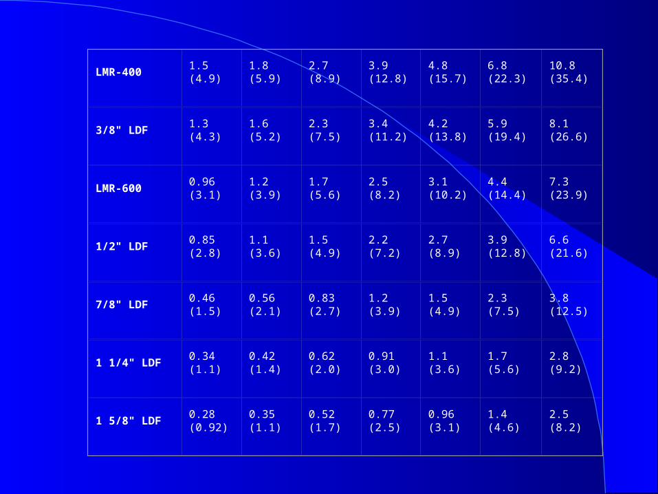
LMR-4001.5 (4.9)
1.8(5.9)
2.7(8.9)
3.9(12.8)
4.8(15.7)
6.8(22.3)
10.8(35.4)
3/8" LDF 1.3 (4.3)
1.6(5.2)
2.3(7.5)
3.4(11.2)
4.2(13.8)
5.9(19.4)
8.1(26.6)
LMR-6000.96 (3.1)
1.2(3.9)
1.7(5.6)
2.5(8.2)
3.1(10.2)
4.4(14.4)
7.3(23.9)
1/2" LDF 0.85 (2.8)
1.1(3.6)
1.5(4.9)
2.2(7.2)
2.7(8.9)
3.9(12.8)
6.6(21.6)
7/8" LDF 0.46 (1.5)
0.56(2.1)
0.83(2.7)
1.2(3.9)
1.5(4.9)
2.3(7.5)
3.8(12.5)
1 1/4" LDF 0.34 (1.1)
0.42(1.4)
0.62(2.0)
0.91(3.0)
1.1(3.6)
1.7(5.6)
2.8(9.2)
1 5/8" LDF 0.28 (0.92)
0.35(1.1)
0.52(1.7)
0.77(2.5)
0.96(3.1)
1.4(4.6)
2.5(8.2)
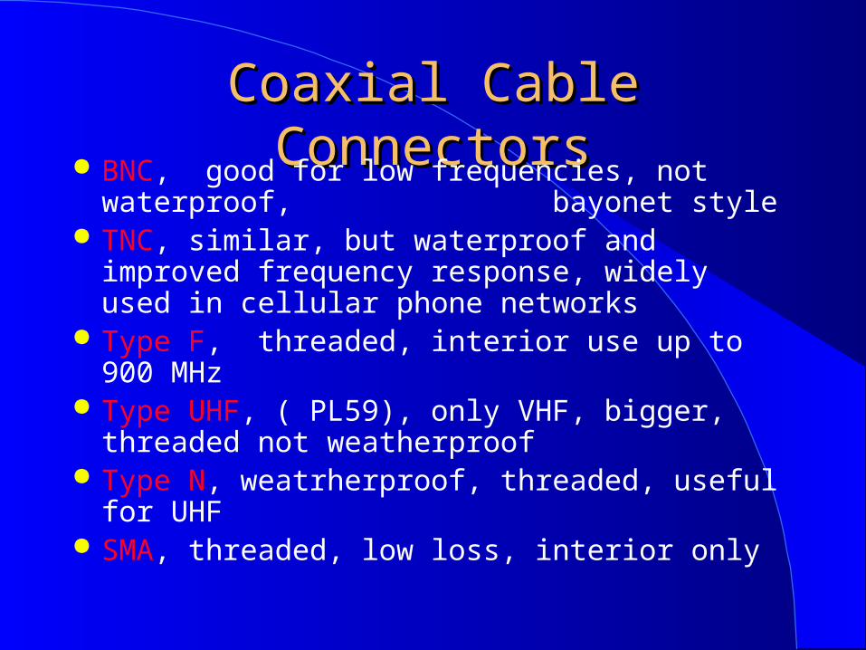
Coaxial Coaxial Cable ConnectorsCable Connectors BNC, good for low frequencies, not waterproof,
bayonet style TNC, similar, but waterproof and improved
frequency response, widely used in cellular phone networks
Type F, threaded, interior use up to 900 MHz Type UHF, ( PL59), only VHF, bigger, threaded
not weatherproof Type N, weatrherproof, threaded, useful for UHF SMA, threaded, low loss, interior only
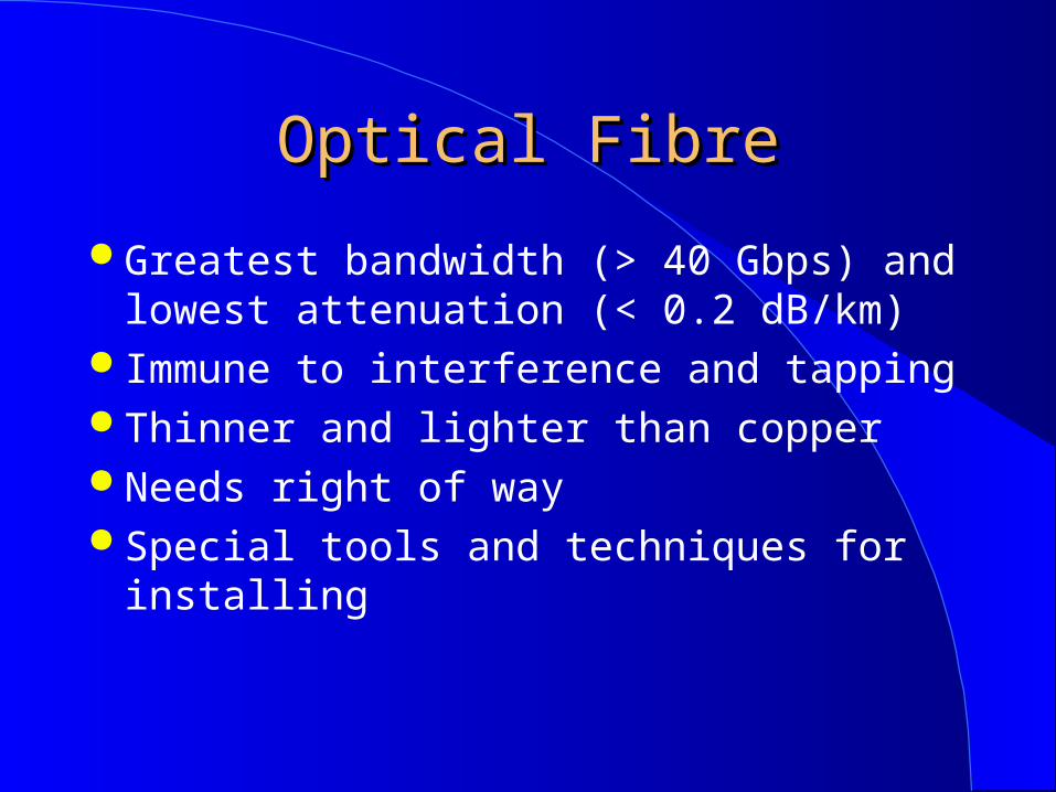
Optical FibreOptical Fibre
Greatest bandwidth (> 40 Gbps) and lowest attenuation (< 0.2 dB/km)
Immune to interference and tapping Thinner and lighter than copper Needs right of way Special tools and techniques for installing
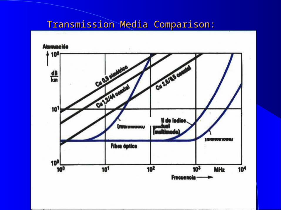
Transmission Media Comparison:Transmission Media Comparison:
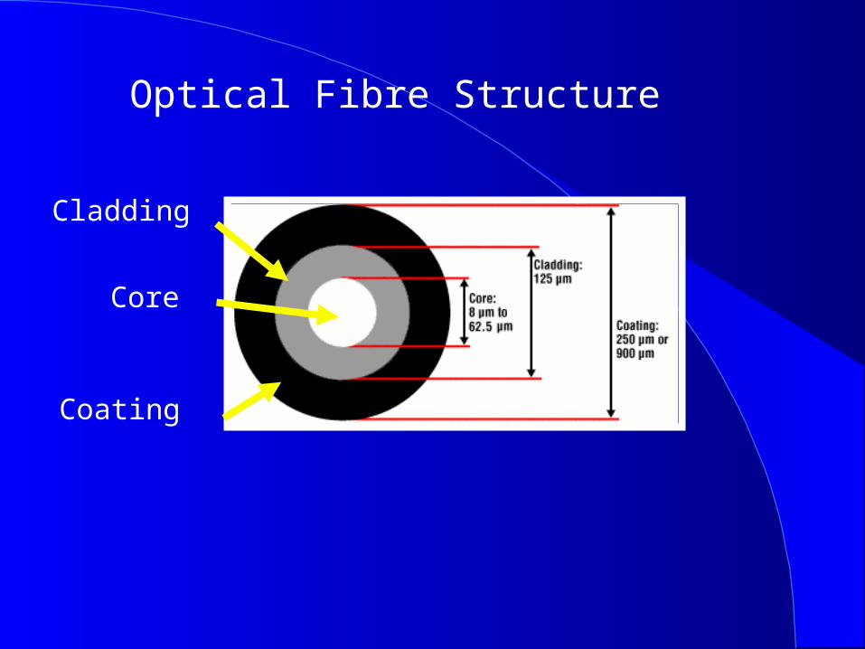
Optical Fibre Structure
Core
Cladding
Coating
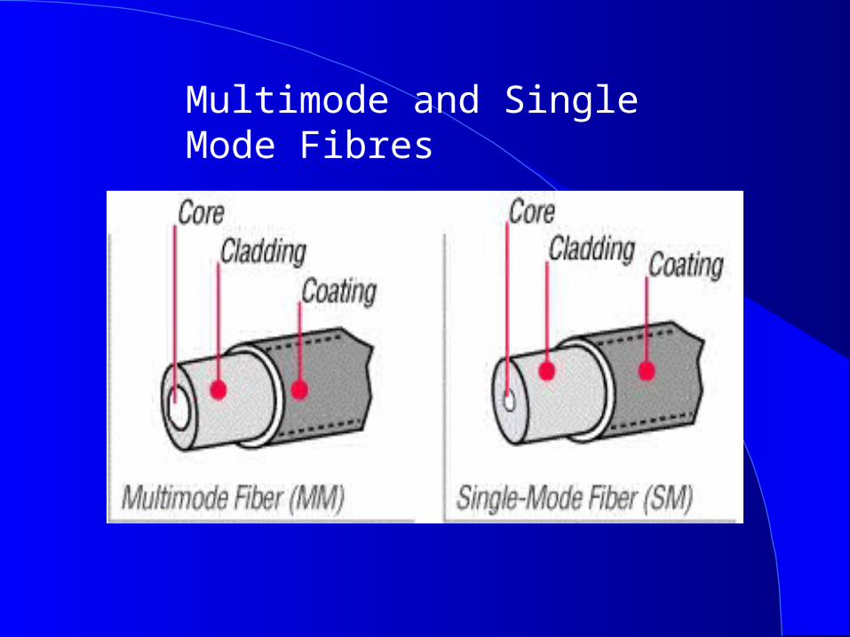
Multimode and Single Mode Fibres


Role of Wiring in Networking
40% of emlpoyees move inside same building each year. 70% of faults cabling related. Cabling represents about 5% of the local network cost. Least subject to obsolescence.
Non Guided MediaNon Guided Media
EM waves can be efficiently radiated by suitable antennas
Since Marconi’s 1898 demonstration of the feasibility of radio communications the spectrum availability in a given area has been steadily increasing
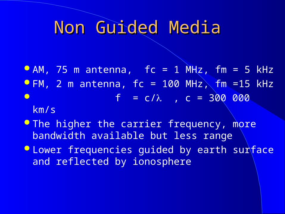
Non Guided Media Non Guided Media
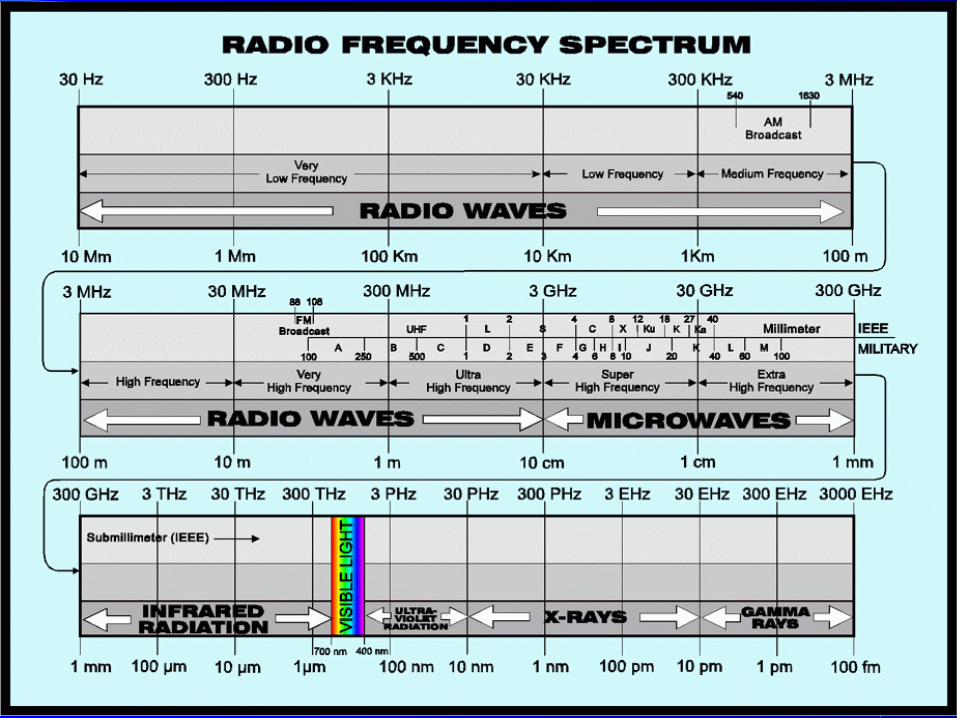
AM, 75 m antenna, fc = 1 MHz, fm = 5 kHz FM, 2 m antenna, fc = 100 MHz, fm =15 kHz f = c/ , c = 300 000 km/s The higher the carrier frequency, more
bandwidth available but less range Lower frequencies guided by earth surface and
reflected by ionosphere
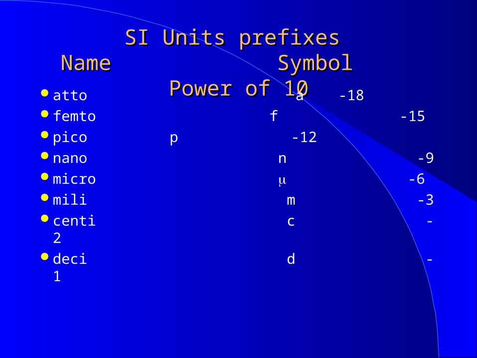
SI Units prefixes SI Units prefixes Name Symbol Power of 10Name Symbol Power of 10
atto a -18 femto f -15 pico p -12 nano n -9 micro -6 mili m -3 centi c -2 deci d -1
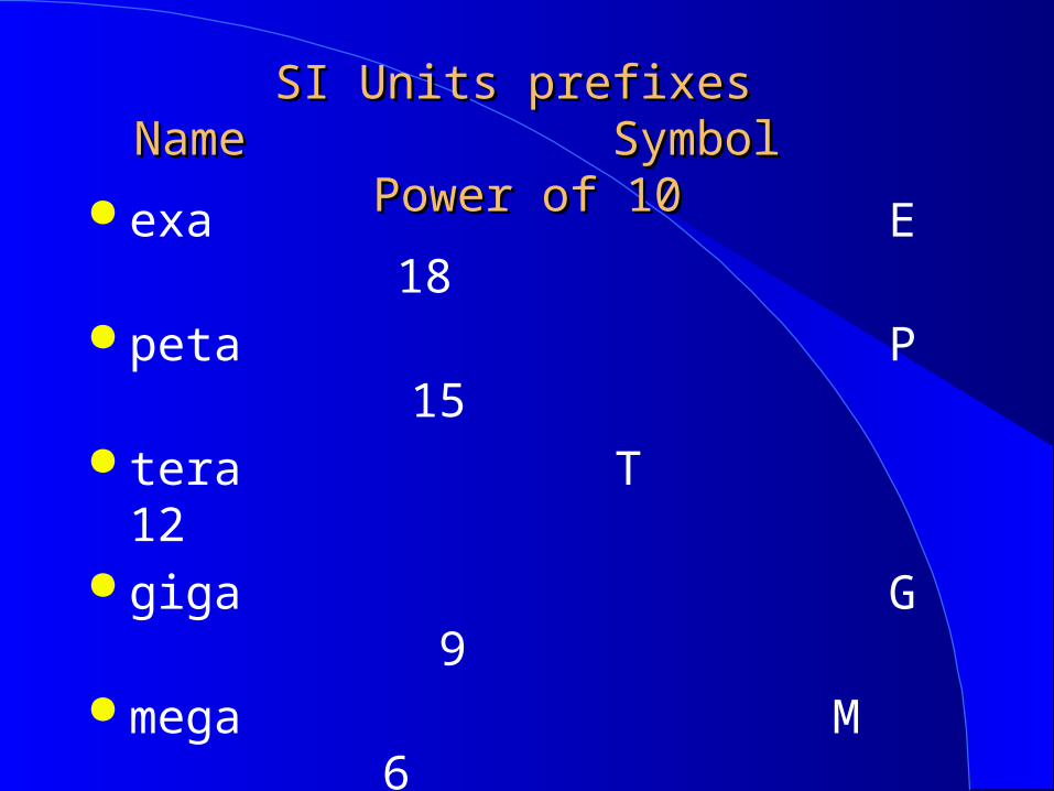
SI Units prefixes SI Units prefixes Name Symbol Power of 10Name Symbol Power of 10
exa E 18 peta P 15 tera T 12 giga G 9 mega M 6 kilo k 3 hecto h 2 deca D 1

Radio Wave PropagationRadio Wave Propagation
Direct wave Ground or Surface wave Reflected Wave Ionosferic Reflection Obstacle Refraction Earth Curvature Multipath
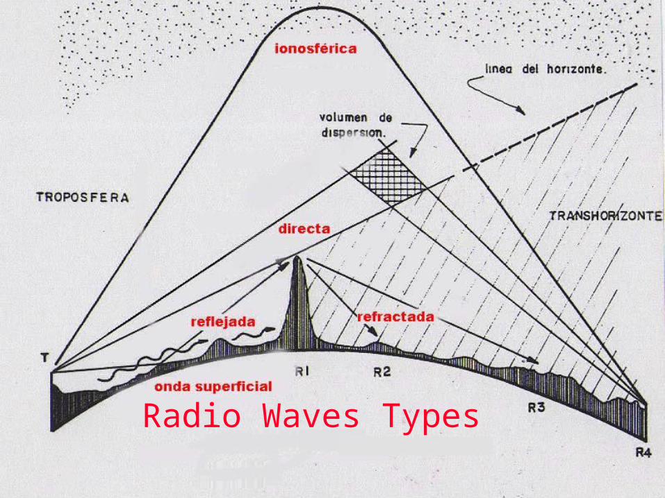
Radio Waves Types
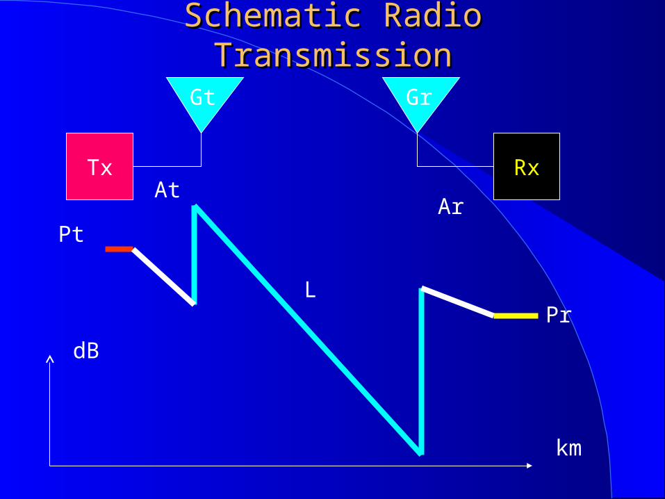
Schematic Radio TransmissionSchematic Radio Transmission
Rx
Gr
Tx
Gt
AtAr
Pr
Pt
L
dB
km
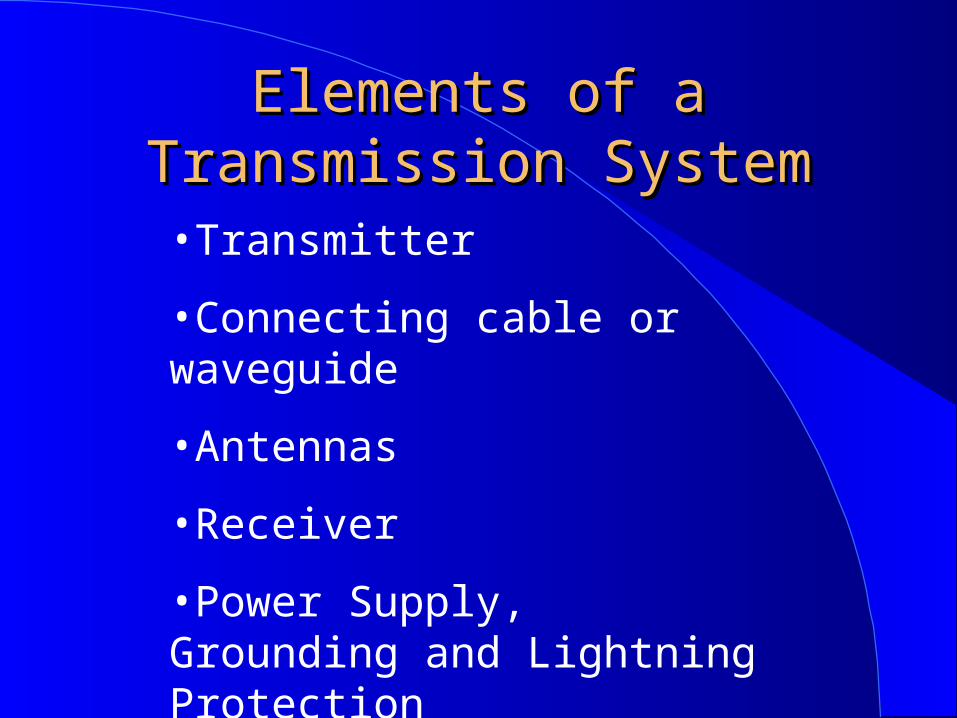
Elements of a Transmission Elements of a Transmission SystemSystem
•Transmitter
•Connecting cable or waveguide
•Antennas
•Receiver
•Power Supply, Grounding and Lightning Protection
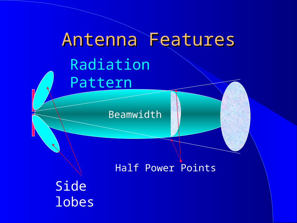
Antenna FeaturesAntenna Features
Beamwidth
Radiation Pattern
Half Power Points
Side lobes
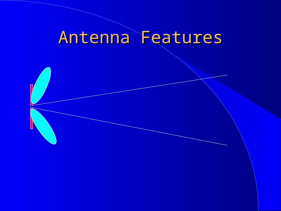
Antenna FeaturesAntenna Features
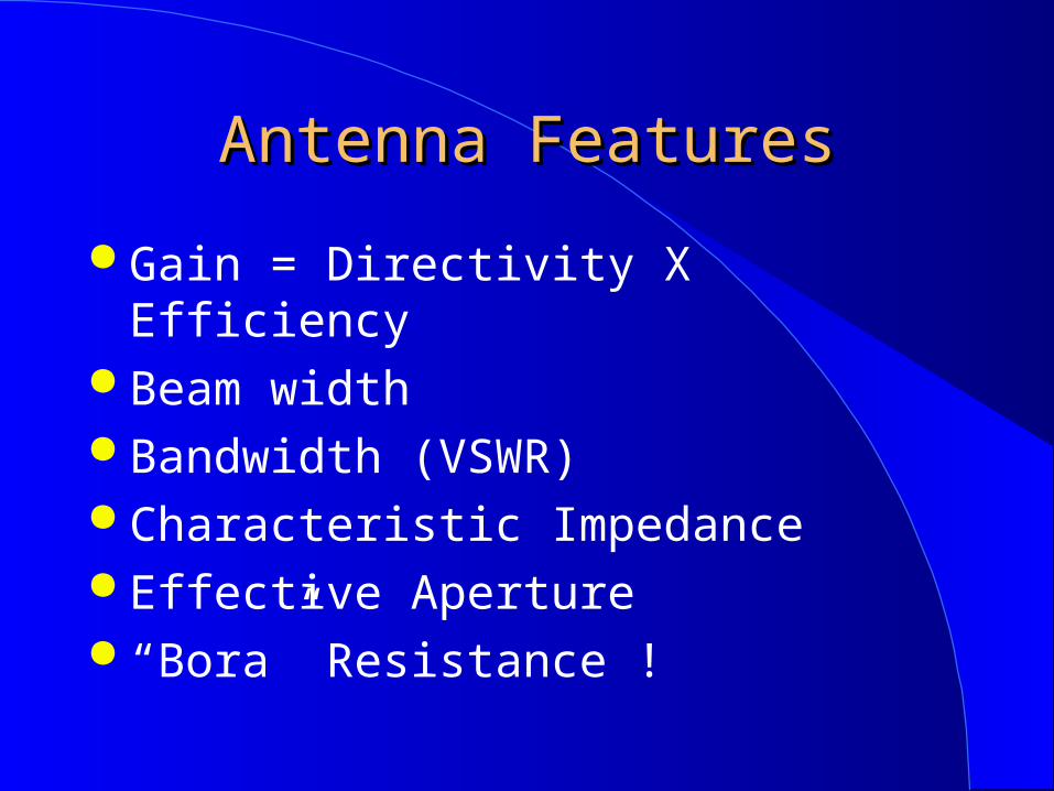
Antenna FeaturesAntenna Features
Gain = Directivity X Efficiency Beam width Bandwidth (VSWR) Characteristic Impedance Effective Aperture “Bora” Resistance !
Antenna PolarizationAntenna Polarization
Polarization corresponds to the direction of the electric field transmitted by the antenna
Vertical Horizontal Elliptyc (RH or LH)
Polarization mismatch can induce up to 20 dB loss
Transmission BandwidthTransmission Bandwidth
Classical systems strive to use as little bandwidth as possible
Alternative systems spread the signal over wide chunks of frequencies, but at a lower power so that the spectrum can be shared
Either systems can yield high spectrum efficiency
Transmission BandwidthTransmission Bandwidth
Narrow SystemsSpread Spectrum SystemsUltra Wide Band
Spread SpectrumSpread Spectrum
(Pseudo Noise Sequence) also called Direct Sequence
(Frequency Hopping)
Spread Spectrum ISM BandsSpread Spectrum ISM Bands
902~928 MHz , USA only
2.4 ~2.484 GHz, Worldwide
5.8 GHz, USA

DSSS Signals SpectrumDSSS Signals Spectrum

Frequency Hopping Frequency Hopping Spread Spread SpectrumSpectrum
frequency
Power

ULTRA WIDE BANDULTRA WIDE BAND
Transmission technique employing very narrow pulses that occupy a very large bandwidth (greater than 25 % of the carrier frequency) but very little power (supposedly indistinguishable from ambient noise), capable of great transmission speed and with imaging and position capabilities
ULTRA WIDE BANDULTRA WIDE BAND ULTRAWIDEBAND GETS FCC NOD, DESPITE
PROTESTS A growing spectrum shortage will not affect
UWB because it shares spectrum with other technologies. The technology also offers easy signal encryption and can be used in small communications devices because of its low power requirements. The FCC plans to address interference concerns by prohibiting the use of UWB below the 3.1 GHz band, as well as restricting the power of UWB devices
(Wall Street Journal, 15 February 2002)
Optical Space TransmissionOptical Space Transmission
Light has been used since antiquity to transmit signals at a distance
The first modern system was built by Chappe in France “Optical Telegraph”
Current systems limited to few kilometers range, but offer speeds up to hundreds of Mbps
Optical Space TransmissionOptical Space Transmission
Local Area NetworksPoint to Point SystemsOuter Space Systems

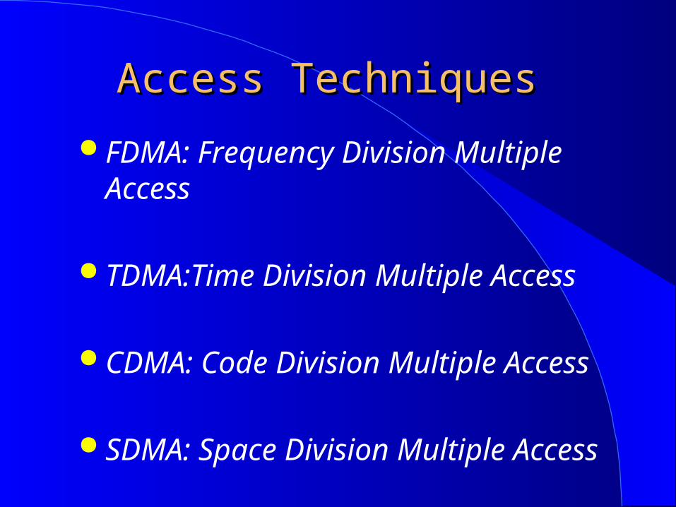
Access TechniquesAccess Techniques
FDMA: Frequency Division Multiple Access
TDMA:Time Division Multiple Access
CDMA: Code Division Multiple Access
SDMA: Space Division Multiple Access
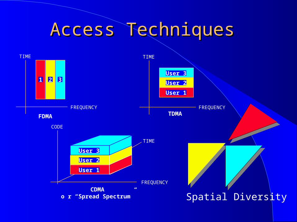
Access TechniquesAccess Techniques
FREQUENCY
TIME
User 3
User 2
User 1
TDMA
TIME
FREQUENCY
CODE
CDMAo r “Spread Spectrum”
User 3
User 2
User 1
FREQUENCY
TIME
FDMA
1 2 3
Spatial Diversity

Duplexing TechniquesDuplexing Techniques
FDD: Frequency Division Duplexing
TDD:Time Division Duplexing
CDD: Code Division Duplexing
SDD: Space Division Duplexing
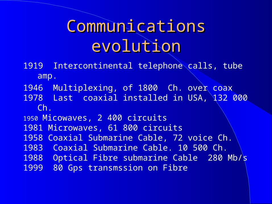
Communications evolutionCommunications evolution
1919 Intercontinental telephone calls, tube amp.
1946 Multiplexing, of 1800 Ch. over coax1978 Last coaxial installed in USA, 132 000 Ch.1950 Micowaves, 2 400 circuits1981 Microwaves, 61 800 circuits1958 Coaxial Submarine Cable, 72 voice Ch.1983 Coaxial Submarine Cable. 10 500 Ch.1988 Optical Fibre submarine Cable 280 Mb/s1999 80 Gps transmssion on Fibre

Communication Systems Growth
Compound annual growth rate over useful life
Terrestrial coax 14.4%
Terrestrial microwave 11%
Undersea fiber 67%
Terrestrial fiber similar to geo satellite, 35%
Telephonic rates have nt diminished with the same speed. AT&T marketing expenditures increased ten fold from 1983 to 1994.
ource:Rate Expectations, by Michael Noll Tele.com, March 6,2000
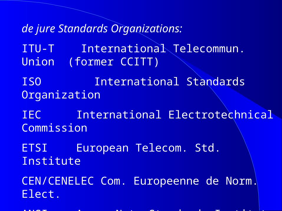
de jure Standards Organizations:
ITU-T International Telecommun. Union (former CCITT)
ISO International Standards Organization
IEC International Electrotechnical Commission
ETSI European Telecom. Std. Institute
CEN/CENELEC Com. Europeenne de Norm. Elect.
ANSI Amer. Nat. Standards Institute
NIST National Institute for Std. & Technology
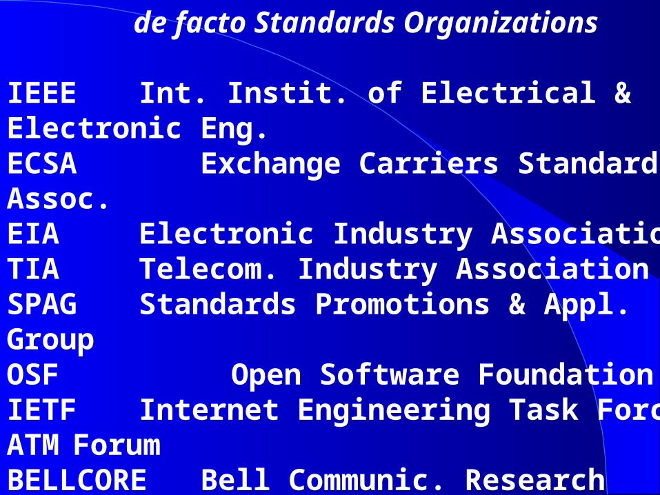
de facto Standards Organizations IEEE Int. Instit. of Electrical & Electronic Eng.ECSA Exchange Carriers Standards Assoc.EIA Electronic Industry AssociationTIA Telecom. Industry AssociationSPAG Standards Promotions & Appl. GroupOSF Open Software FoundationIETF Internet Engineering Task ForceATM ForumBELLCORE Bell Communic. Research (Telcordia)ECMA European Computer Manufacturers Assoc.CEPT Conf. European of Posts et Telecomm.