Embed Size (px)
Citation preview

18
35Image courtesy of CAMBCO Inc.
36Cambering is the process of creating an intentional slight curvature in a beam
Introduction to Cambering
Image courtesy of CAMBCO Inc.

19
37
• Camber is usually designed to compensate for deflections caused by pre-composite dead loads
• Camber in a beam can be designed to compensate for either:
A certain percentage of the dead load deflection
The full dead load deflection
The full dead load deflection as well as a percentage of the live load deflection (Ricker 1989)
Introduction to Cambering
38
• Supporting beams will deflect under the load of concrete being placed
• This deflection can be exaggerated in a composite floor system where the full strength of the system is not achieved until the concrete has cured
• Cambered beams (top diagram above) should deflect to a straight line (bottom diagram above), if load and deflection are predicted accurately and camber equals deflection
This allows the floor slab to be flat while maintaining a consistent thickness (Larson and Huzzard 1990)
Advantages of Cambering
20
39
• If beams are not cambered (top diagram above) the deflection under the load of the wet (plastic) concrete will result in a ponding effect in the concrete (bottom diagram above)
• To create a flat floor in this situation the concrete will need to be thicker at the center of the bay where the deflection is the greatest
• The volume of concrete used will typically be 10-15% more than if the floor is a constant thickness (ASCE 2002)
Advantages of Cambering
40
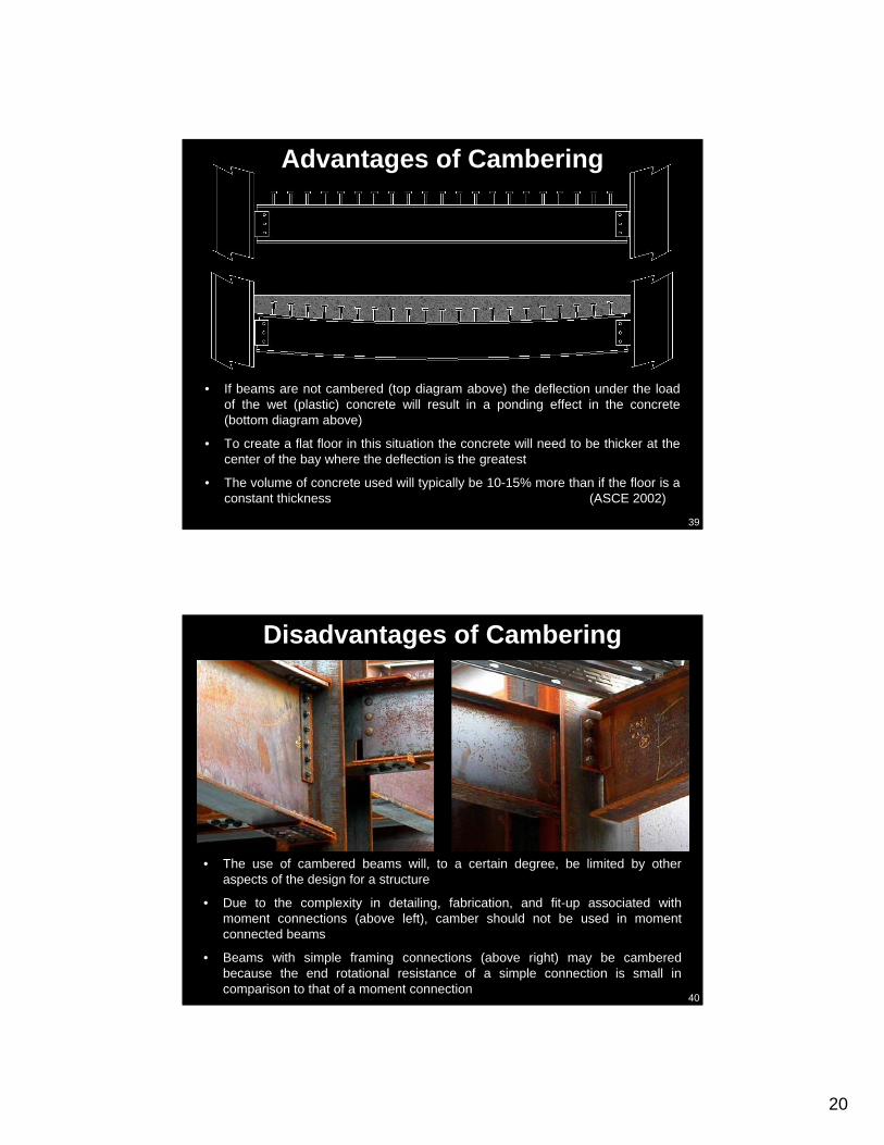
• The use of cambered beams will, to a certain degree, be limited by other aspects of the design for a structure
• Due to the complexity in detailing, fabrication, and fit-up associated with moment connections (above left), camber should not be used in moment connected beams
• Beams with simple framing connections (above right) may be cambered because the end rotational resistance of a simple connection is small in comparison to that of a moment connection
Disadvantages of Cambering
21
41
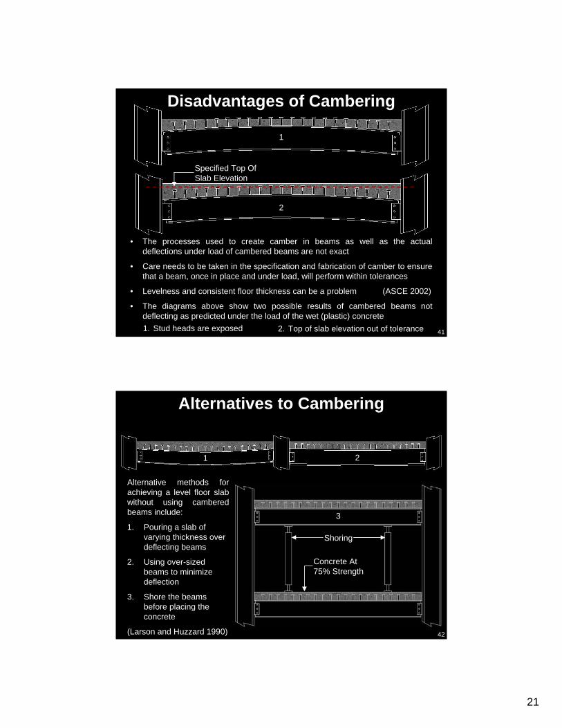
• The processes used to create camber in beams as well as the actual deflections under load of cambered beams are not exact
• Care needs to be taken in the specification and fabrication of camber to ensure that a beam, once in place and under load, will perform within tolerances
• Levelness and consistent floor thickness can be a problem (ASCE 2002)
• The diagrams above show two possible results of cambered beams not deflecting as predicted under the load of the wet (plastic) concrete
Disadvantages of Cambering
1. Stud heads are exposed 2. Top of slab elevation out of tolerance
Specified Top Of Slab Elevation
1
2
42
Alternative methods for achieving a level floor slab without using cambered beams include:
1. Pouring a slab of varying thickness over deflecting beams
2. Using over-sized beams to minimize deflection
3. Shore the beams before placing the concrete
(Larson and Huzzard 1990)
Alternatives to Cambering
1 2
3
Shoring
Concrete At 75% Strength

22
43
• Shoring may be used in lieu of cambering
• The construction documents must specify the use of shoring
• There are several advantages to using shoring:
Lighter floor beams may be used
Cambers do not need to be designed or fabricated
Less beam deflection allows for better control of the slab thickness
Shoring can accommodate a contractor’s special loading requirements
Shoring
44
• Girder Beams
• Members with uniform cross section
• Filler Beams
• Composite Floor Beams
(Ricker 1989)
When to Camber
23
45
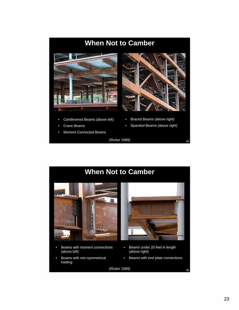
• Braced Beams (above right)
• Spandrel Beams (above right)
• Cantilevered Beams (above left)
• Crane Beams
• Moment Connected Beams
When Not to Camber
(Ricker 1989)
46
• Beams under 20 feet in length (above right)
• Beams with end plate connections
• Beams with moment connections (above left)
• Beams with non-symmetrical loading
When Not to Camber
(Ricker 1989)

24
47
• Beams may be cambered by applying heat to small wedge-shaped areas at specific increments along the beam (Ricker 1989)
• The beam is place upside down on supports so the “bottom” flange can be heated
• The heated flange expands under the heat and contracts as it cools
• Camber is induced in the opposite side of the beam as the heated flange cools
• Advancing this slide will begin an animation which shows the expansion and contraction that occurs in a heat cambered beamThe animation will repeat after several seconds
Heat Cambering
Beam
Support
Heated Areas
Top Side of Beam When Installed
48
• A heat cambered beam should be erected with the heat marks on the bottom side of the beam (see top diagram above)
This places the beam in a camber up (or concave down) orientation
• Heat marks can be seen on the beams in the bottom picture above
Installation of Heat Cambered Beams

25
49
• Cold cambering methods are more widely used and generally more economical than heat cambering
• The beam is mounted in a frame and force from a ram(s) is used to bend the beam to create camber
(Ricker 1989)
Cold Cambering
Image courtesy of CAMBCO Inc.
50
• Cambering is most commonly done at the fabricator’s shop after the connections are fabricated (AISC 2000)
• The fabricator may mark cambered beams to ensure proper installation
Creating Camber
Image courtesy of CAMBCO Inc.

26
51
• Natural mill camber, which is a slight camber present in a beam when it is received from the mill, will exist in most beams
• If the natural mill camber is at least 75% of the specified camber, no further cambering by the fabricator is required
• If camber is not specified, the beams will be fabricated and erected with any natural mill camber oriented up (or concave down) (AISC 2000)
Natural Mill Camber
52
Cambered beams should be clearly marked on the structural plans (AISC 2000)
Cambered Beams on Structural Plans
27
53
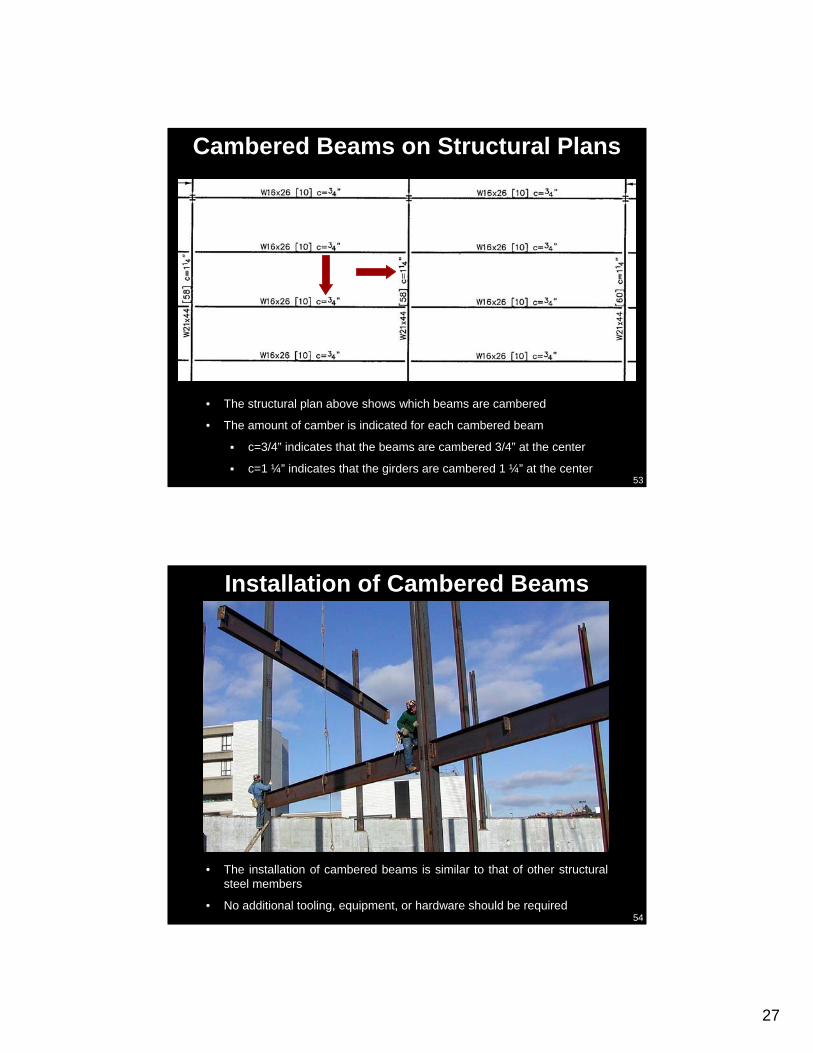
• The structural plan above shows which beams are cambered
• The amount of camber is indicated for each cambered beam
c=3/4” indicates that the beams are cambered 3/4” at the center
c=1 ¼” indicates that the girders are cambered 1 ¼” at the center
Cambered Beams on Structural Plans
54
• The installation of cambered beams is similar to that of other structural steel members
• No additional tooling, equipment, or hardware should be required
Installation of Cambered Beams

28
55
• Per the AISC Code of Standard Practice “camber shall be measured in the Fabricator’s shop in the unstressed condition.” (above left)
The amount of camber specified on the shop drawing (above right) is for the beam center line in an unstressed or unloaded condition
• Tolerances for camber are specified in the AISC Code of Standard Practice:
Members 50 feet or less in length = minus 0” and plus 1/2”
Members over 50 feet the plus tolerance is increased by 1/8” for every 10 feet over 50 feet
(AISC 2000)
Quality Control
56
• It is possible for all or part of the induced camber to come out of a beam during shipment to a jobsite
• This is acceptable under the AISC Code of Standard Practice (2000), but the fabricator’s quality control procedure should provide verification that thespecified camber was measured in the shop
Quality Control
29
57
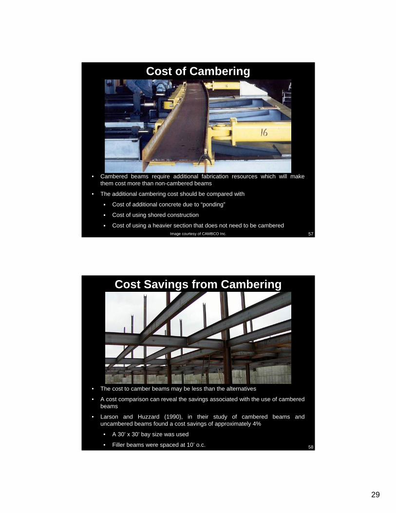
• Cambered beams require additional fabrication resources which will make them cost more than non-cambered beams
• The additional cambering cost should be compared with
Cost of additional concrete due to “ponding”
Cost of using shored construction
Cost of using a heavier section that does not need to be cambered
Cost of Cambering
Image courtesy of CAMBCO Inc.
58
• The cost to camber beams may be less than the alternatives
• A cost comparison can reveal the savings associated with the use of cambered beams
• Larson and Huzzard (1990), in their study of cambered beams and uncambered beams found a cost savings of approximately 4%
• A 30’ x 30’ bay size was used
• Filler beams were spaced at 10’ o.c.
Cost Savings from Cambering

30
59
• There will be an increase in fabrication duration for structural steel to account for time required to create camber in beams
• The amount of time required to create camber is dependent on a fabricator’s internal scheduling and fabrication methods
Impacts on the Schedule
Image courtesy of CAMBCO Inc.
60
Delivery, shakeout, and erection durations should not be impacted by the use of cambered beams
Impacts on the Schedule