Embed Size (px)
Citation preview
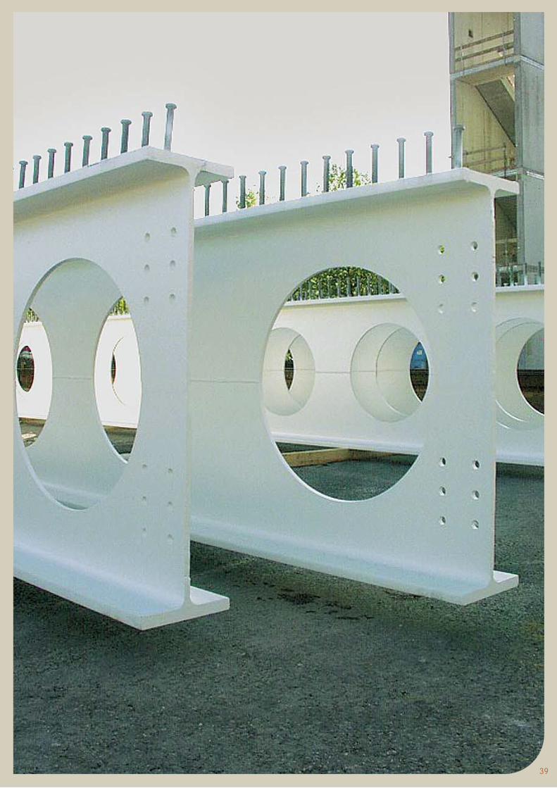
ACB®Cellular Beams
ArcelorMittal Europe - Long ProductsSections and Merchant Bars
The intelligent solution for long spans
1
Contents
1
1. Introduction 3
2. Application fields 4
3. Concept – fabrication 6
4. Tolerances of ACB® beams 13
5. Symmetrical cellular beams in roofing and metal decking applications 15
6. Asymmetric cellular beams in composite floor application 21
7. Stability in fire and fire safety 25
8. ACB® design charts 27
9. Design charts: design examples 35
10. ACB+ Software 38
11. ACB® beams: a solution for sustainable development 39
12. AngelinaTM castellated beams with sinusoidal openings 42
Technical assistance & finishing
Your partners
3
1. Introduction
During more than ten years, there has been an increase in the use of cellular beams, both in metal structures and in exploring new structural solutions.
The use of cellular beams allows a new architectural expression. Structures are lightened and spans increased, pulling spaces together. This flexibility goes together with the functionality of allowing technical installations (pipes and ducts) to pass through the openings. The lightweight appearance of cellular beams, combined with their high strength, never ceases to inspire architects to new structural forms.
Progress has now been made on a number of factors that enable the use of cellular beams to be extended:
l Manufacture The optimisation of manufacturing methods (flame cutting, bending, etc.) now makes it possible to adapt to the requirements of project owners and guarantee rapid delivery of cellular beams.
l Standardisation The Eurocodes (Eurocode 3 for steel structures and Eurocode 4 for composite structures) provide answers to the calculation of strength in normal use, for fire accident situations and with regard to the use of S460 high strength steel.
l Composite construction The mastery of the various aspects of composite steel and concrete construction - making the bond, use of linked trays, floating plates, fire resistance, user comfort and durability – has greatly contributed to the “ACB® cellular beams” solution in floors.
l Design tools The development of a high-performance design and calculation tool (ACB+ software), available to design offices and architects, favours the use of cellular beams. The methods adopted in this software exploit the results of tests on full-size beams and of many digital simulations.
2. Application fields
1. Roofing
The use of ACB® as roofing elements enables large spans, in the region of 40 metres, to be covered. Whether used as independent elements (simply supported beams) or continuity elements (frame rafter), the competitiveness of the ACB® solution is confirmed both by the retention of the functionalities of lattice beams and by the reduction of on-site interventions for assembly.
ACB® beams offer architects attractive and practical solutions in terms of use of space without screening effect. The diameter of the openings can reach 80 % of the total height of the beam and it is possible to leave only a small distance – required for fabrication – between the openings. This configuration of ACB® beams enables their transparency and blending into the space enclosed to be accentuated, which has great appeal for architects.
2. Decking
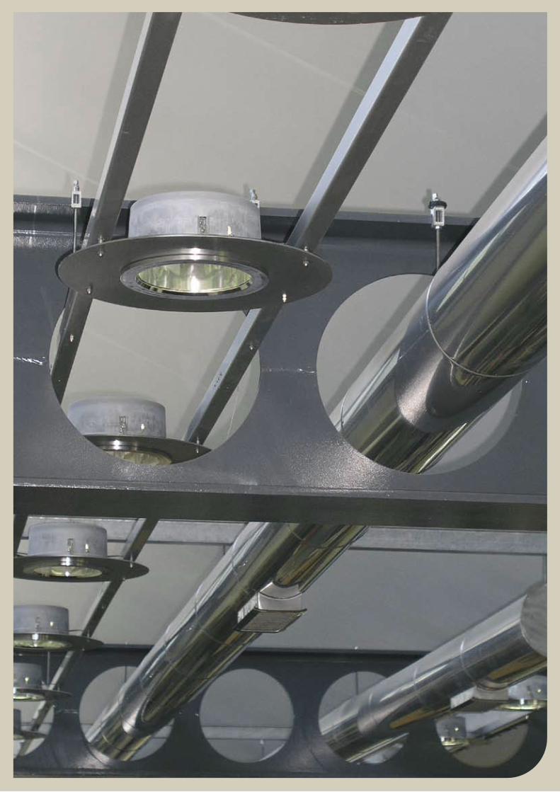
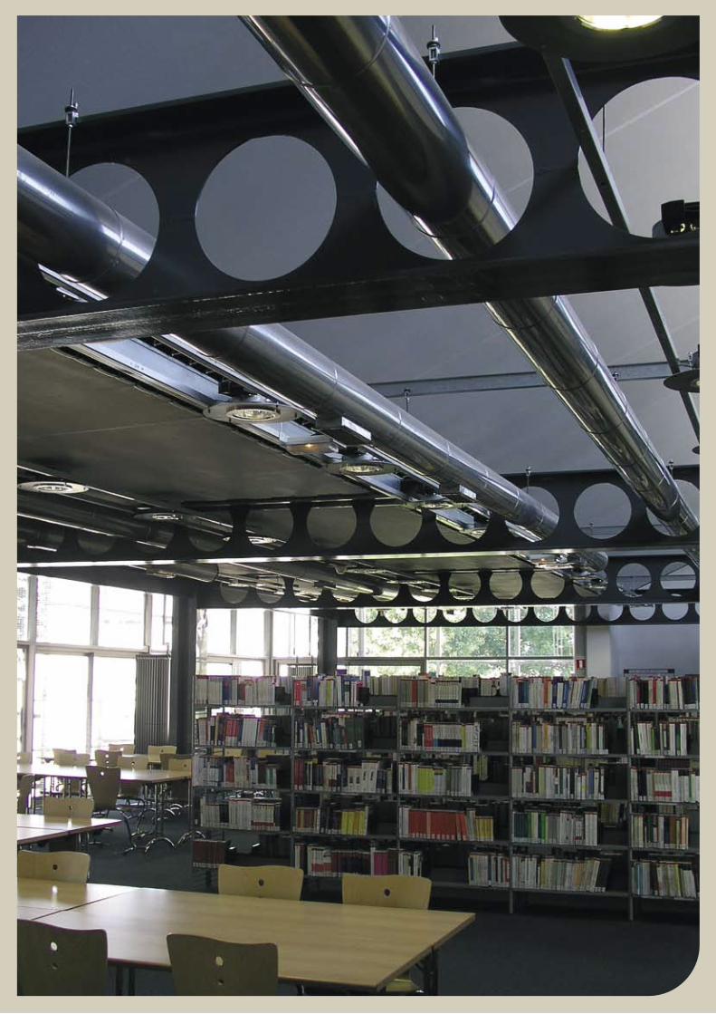
Modern constructions increasingly demand the accommodation of technical installations (heating, ventilation, air conditioning, etc.) within the available space enclosed.
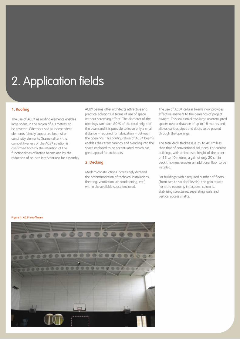
Figure 1: ACB® roof beam
The use of ACB® cellular beams now provides effective answers to the demands of project owners. This solution allows large uninterrupted spaces over a distance of up to 18 metres and allows various pipes and ducts to be passed through the openings.
The total deck thickness is 25 to 40 cm less than that of conventional solutions. For current buildings, with an imposed height of the order of 35 to 40 metres, a gain of only 20 cm in deck thickness enables an additional floor to be installed.
For buildings with a required number of floors (from two to six deck levels), the gain results from the economy in façades, columns, stabilising structures, separating walls and vertical access shafts.
5
3. Special applications
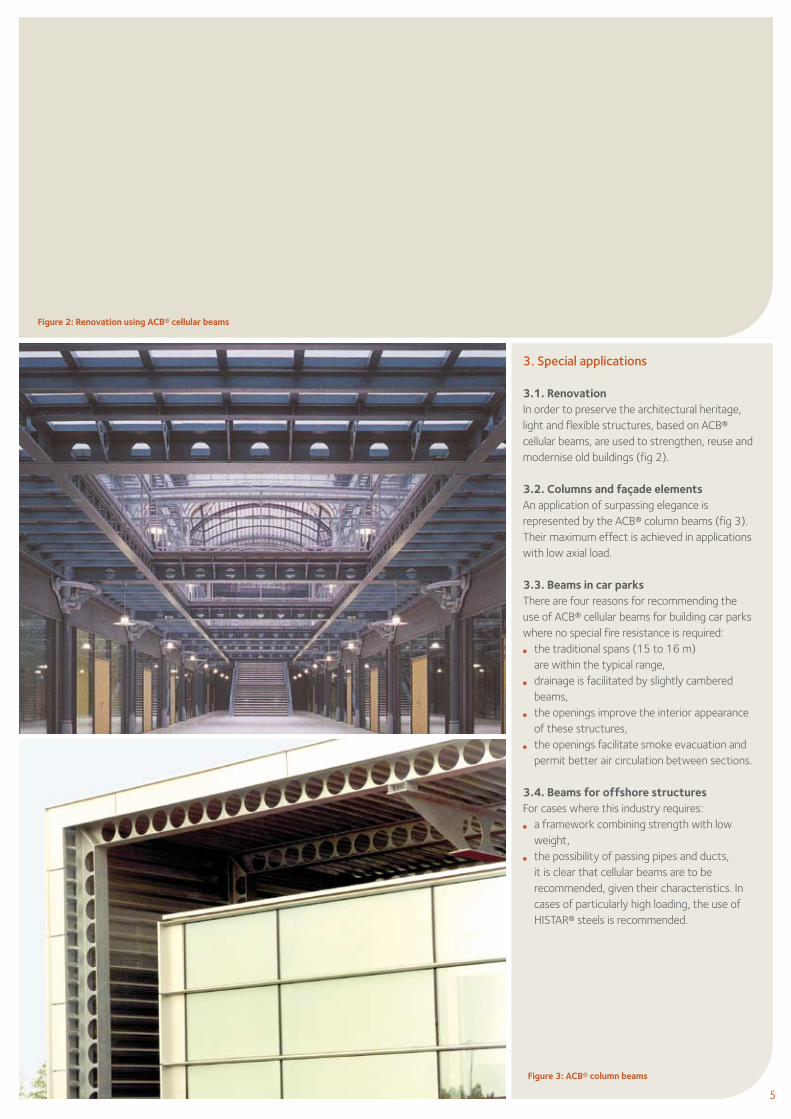
3.1. Renovation In order to preserve the architectural heritage, light and flexible structures, based on ACB® cellular beams, are used to strengthen, reuse and modernise old buildings (fig 2).
3.2. Columns and façade elements An application of surpassing elegance is represented by the ACB® column beams (fig 3). Their maximum effect is achieved in applications with low axial load.
3.3. Beams in car parks There are four reasons for recommending the use of ACB® cellular beams for building car parks where no special fire resistance is required: l the traditional spans (15 to 16 m) are within the typical range, l drainage is facilitated by slightly cambered
beams,l the openings improve the interior appearance
of these structures,l the openings facilitate smoke evacuation and
permit better air circulation between sections.
3.4. Beams for offshore structures For cases where this industry requires: l a framework combining strength with low
weight,l the possibility of passing pipes and ducts,
it is clear that cellular beams are to be recommended, given their characteristics. In cases of particularly high loading, the use of HISTAR® steels is recommended.
.
Figure 3: ACB® column beams
Figure 2: Renovation using ACB® cellular beams
3. Concept – fabrication
ACB® beams are fabricated in modern installations on site of ArcelorMittal’s rolling mill for heavy sections at Differdange (Luxembourg). The proximity of these installations limits transport, maximises responsiveness and contributes to the competitiveness of the manufacturing costs.
The patented method used for the fabrication of ACB® cellular beams is based on the exclusive use of hot rolled sections.
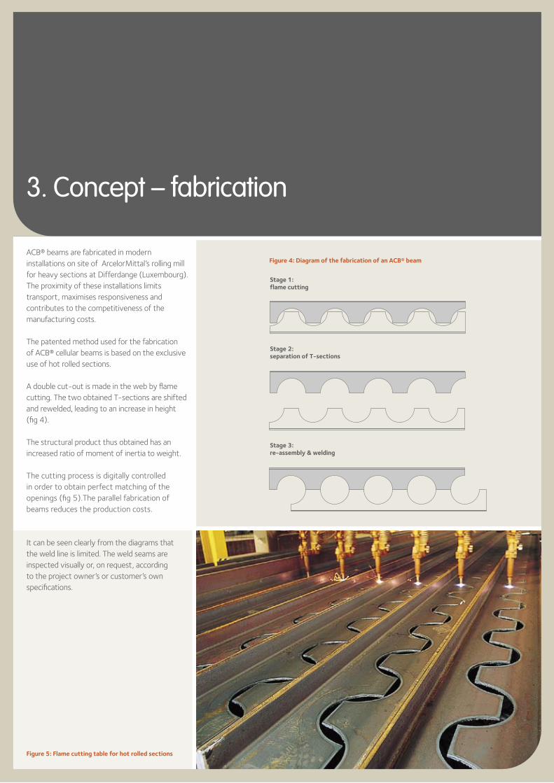
A double cut-out is made in the web by flame cutting. The two obtained T-sections are shifted and rewelded, leading to an increase in height (fig 4).
The structural product thus obtained has an increased ratio of moment of inertia to weight.
The cutting process is digitally controlled in order to obtain perfect matching of the openings (fig 5).The parallel fabrication of beams reduces the production costs.
It can be seen clearly from the diagrams that the weld line is limited. The weld seams are inspected visually or, on request, according to the project owner’s or customer’s own specifications.
Figure 5: Flame cutting table for hot rolled sections
Figure 4: Diagram of the fabrication of an ACB® beam
Stage 1:flame cutting
Stage 2:separation of T-sections
Stage 3:re-assembly & welding
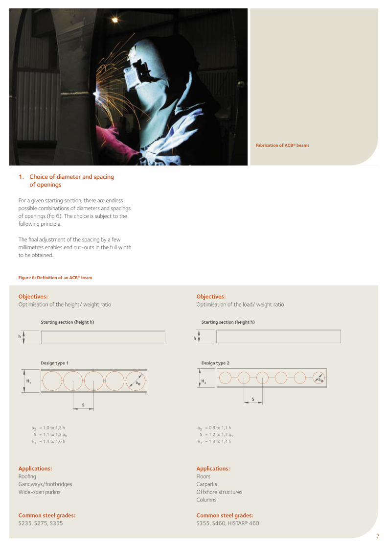
Objectives:Optimisation of the load/ weight ratio
Applications:FloorsCarparksOffshore structuresColumns
Common steel grades:S355, S460, HISTAR® 460
Objectives:Optimisation of the height/ weight ratio
Applications:RoofingGangways/footbridgesWide-span purlins
Common steel grades:S235, S275, S355
Fabrication of ACB® beams
1. Choice of diameter and spacing of openings
For a given starting section, there are endless possible combinations of diameters and spacings of openings (fig 6). The choice is subject to the following principle.
The final adjustment of the spacing by a few millimetres enables end cut-outs in the full width to be obtained.
Figure 6: Definition of an ACB® beam
ao = 1,0 to 1,3 h
S = 1,1 to 1,3 aoH1 = 1,4 to 1,6 h
ao = 0,8 to 1,1 h
S = 1,2 to 1,7 aoH2 = 1,3 to 1,4 h
ao
h h
SS
H2H1
7
Starting section (height h)
Design type 1
Starting section (height h)
Design type 2
ao
2. Choice of longitudinal profile
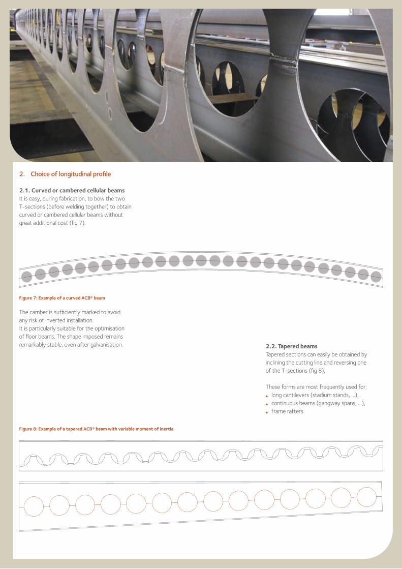
2.1. Curved or cambered cellular beams It is easy, during fabrication, to bow the two T-sections (before welding together) to obtain curved or cambered cellular beams without great additional cost (fig 7).
The camber is sufficiently marked to avoid any risk of inverted installation. It is particularly suitable for the optimisation of floor beams. The shape imposed remains remarkably stable, even after galvanisation.
Figure 7: Example of a curved ACB® beam
Figure 8: Example of a tapered ACB® beam with variable moment of inertia
2.2. Tapered beamsTapered sections can easily be obtained by inclining the cutting line and reversing one of the T-sections (fig 8).
These forms are most frequently used for: l long cantilevers (stadium stands, …), l continuous beams (gangway spans, …), l frame rafters.
9
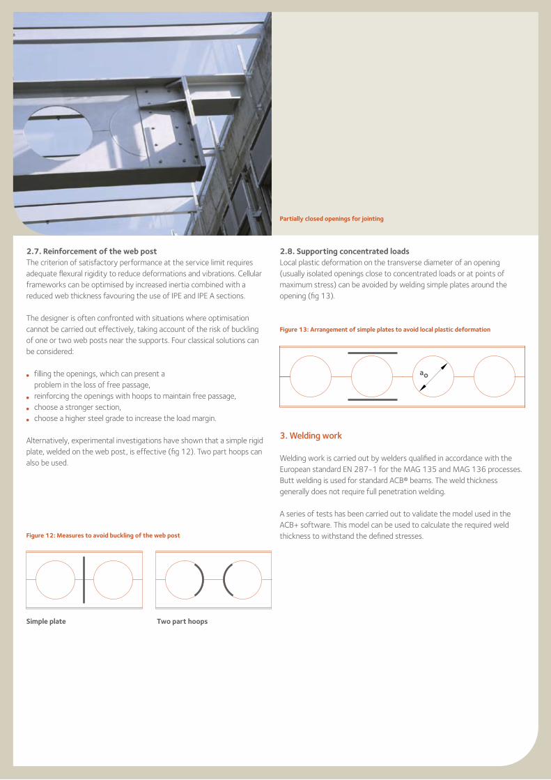
Figure 11b: Example of ACB® beam with reinforced opening
Figure 11a: Example of ACB® beam with filled openings
Figure 10: Example of ACB® beam with elongated opening
9
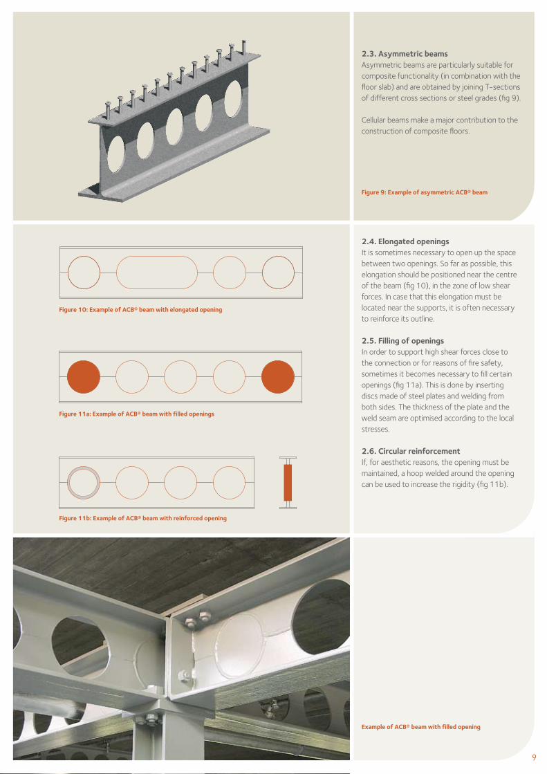
2.3. Asymmetric beams Asymmetric beams are particularly suitable for composite functionality (in combination with the floor slab) and are obtained by joining T-sections of different cross sections or steel grades (fig 9).
Cellular beams make a major contribution to the construction of composite floors.
2.4. Elongated openingsIt is sometimes necessary to open up the space between two openings. So far as possible, this elongation should be positioned near the centre of the beam (fig 10), in the zone of low shear forces. In case that this elongation must be located near the supports, it is often necessary to reinforce its outline.
2.5. Filling of openings In order to support high shear forces close to the connection or for reasons of fire safety, sometimes it becomes necessary to fill certain openings (fig 11a). This is done by inserting discs made of steel plates and welding from both sides. The thickness of the plate and the weld seam are optimised according to the local stresses.
2.6. Circular reinforcement If, for aesthetic reasons, the opening must be maintained, a hoop welded around the opening can be used to increase the rigidity (fig 11b).
Figure 9: Example of asymmetric ACB® beam
Example of ACB® beam with filled opening
2.7. Reinforcement of the web postThe criterion of satisfactory performance at the service limit requires adequate flexural rigidity to reduce deformations and vibrations. Cellular frameworks can be optimised by increased inertia combined with a reduced web thickness favouring the use of IPE and IPE A sections.
The designer is often confronted with situations where optimisation cannot be carried out effectively, taking account of the risk of buckling of one or two web posts near the supports. Four classical solutions can be considered:
l filling the openings, which can present a problem in the loss of free passage,
l reinforcing the openings with hoops to maintain free passage,l choose a stronger section,l choose a higher steel grade to increase the load margin.
Alternatively, experimental investigations have shown that a simple rigid plate, welded on the web post, is effective (fig 12). Two part hoops can also be used.
2.8. Supporting concentrated loads Local plastic deformation on the transverse diameter of an opening (usually isolated openings close to concentrated loads or at points of maximum stress) can be avoided by welding simple plates around the opening (fig 13).
3. Welding work
Welding work is carried out by welders qualified in accordance with the European standard EN 287-1 for the MAG 135 and MAG 136 processes. Butt welding is used for standard ACB® beams. The weld thickness generally does not require full penetration welding.
A series of tests has been carried out to validate the model used in the ACB+ software. This model can be used to calculate the required weld thickness to withstand the defined stresses. Figure 12: Measures to avoid buckling of the web post
Figure 13: Arrangement of simple plates to avoid local plastic deformation
ao
Partially closed openings for jointing
Simple plate Two part hoops
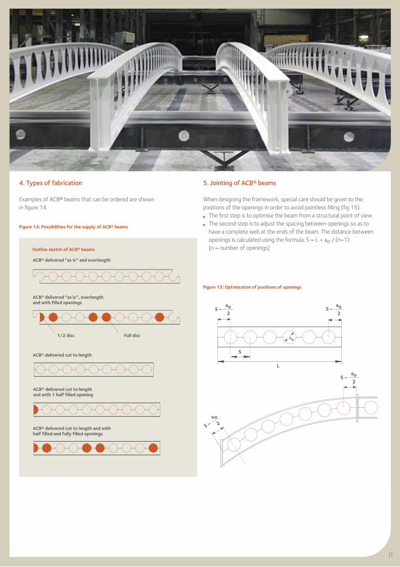
Figure 14: Possibilities for the supply of ACB® beams
Figure 15: Optimisation of positions of openings
S
S –ao2
ao2
ao
L
S –ao2
S –a o
2
4. Types of fabrication
Examples of ACB® beams that can be ordered are shown in figure 14.
11
5. Jointing of ACB® beams
When designing the framework, special care should be given to the positions of the openings in order to avoid pointless filling (fig 15). l The first step is to optimise the beam from a structural point of view. l The second step is to adjust the spacing between openings so as to
have a complete web at the ends of the beam. The distance between openings is calculated using the formula: S = L + ao / (n+1)
[n = number of openings]
S –
Outline sketch of ACB® beams
ACB® delivered “as is” and overlength
ACB® delivered “as is”, overlength and with filled openings
1/2 disc Full disc
ACB® delivered cut to length
ACB® delivered cut to length and with 1 half filled opening
ACB® delivered cut to length and withhalf filled and fully filled openings
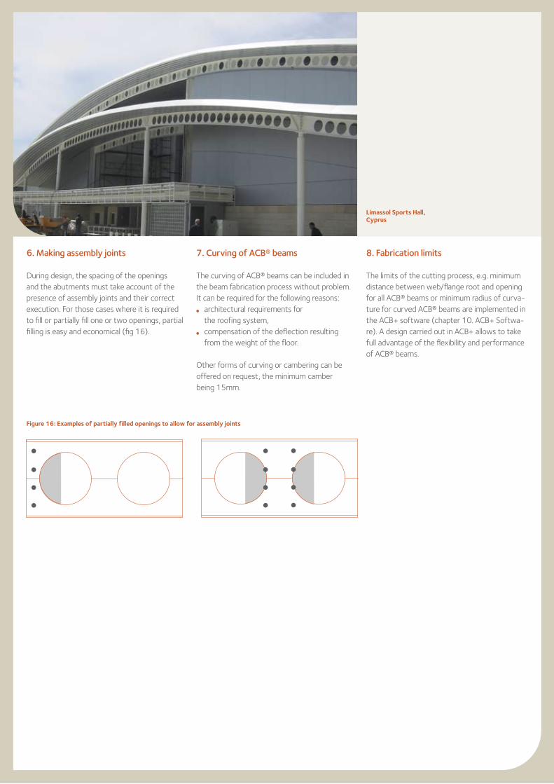
Figure 16: Examples of partially filled openings to allow for assembly joints
6. Making assembly joints
During design, the spacing of the openings and the abutments must take account of the presence of assembly joints and their correct execution. For those cases where it is required to fill or partially fill one or two openings, partial filling is easy and economical (fig 16).
Limassol Sports Hall,Cyprus
8. Fabrication limits
The limits of the cutting process, e.g. minimum distance between web/flange root and opening for all ACB® beams or minimum radius of curva-ture for curved ACB® beams are implemented in the ACB+ software (chapter 10. ACB+ Softwa-re). A design carried out in ACB+ allows to take full advantage of the flexibility and performance of ACB® beams.
7. Curving of ACB® beams
The curving of ACB® beams can be included in the beam fabrication process without problem. It can be required for the following reasons:l architectural requirements for
the roofing system, l compensation of the deflection resulting
from the weight of the floor.
Other forms of curving or cambering can be offered on request, the minimum camber being 15mm.
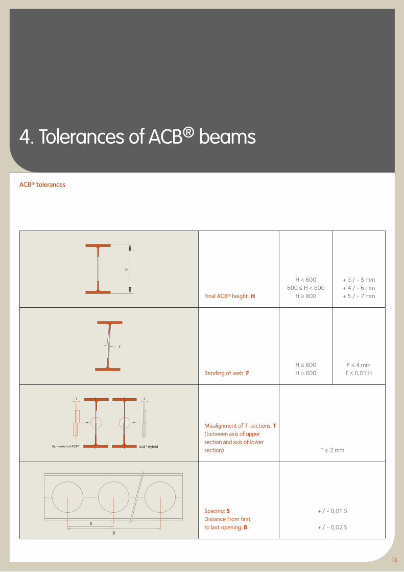
Final ACB® height: H
H < 600600 ≤ H < 800
H ≥ 800
+ 3 / - 5 mm+ 4 / - 6 mm+ 5 / - 7 mm
Bending of web: FH ≤ 600H > 600
F ≤ 4 mmF ≤ 0,01 H
Misalignment of T-sections: T (between axis of upper section and axis of lower section) T ≤ 2 mm
Spacing: S Distance from first to last opening: B
+ / - 0,01 S
+ / - 0,02 S
4. Tolerances of ACB® beams
T T
B
S
H
F
ACB® tolerances
13
Symmetrical ACB® ACB® Hybrid
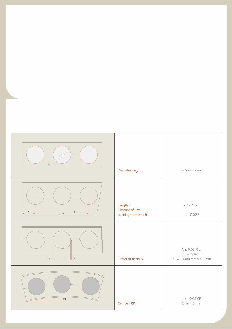
Diameter: ao + 5 / - 2 mm
Length: L Distance of 1st opening from end: A
+ / - 2 mm
+ /- 0,02 S
Offset of risers: V
V ≤ 0.03 % LExample :
If L = 10000 mm V ≤ 3 mm
Camber: CF + / - 0,05 CFCF min. 5 mm
CF
VV
ao
A SL
15
5. Symmetrical cellular beams in roofing and metal decking applications
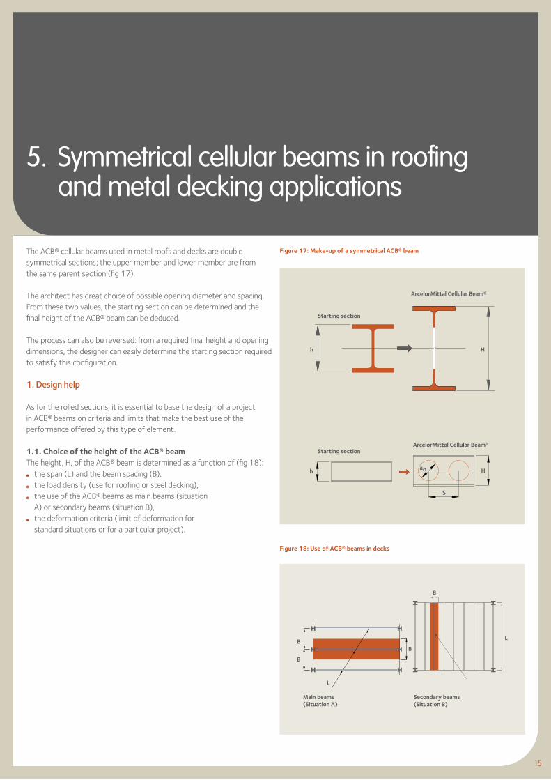
The ACB® cellular beams used in metal roofs and decks are double symmetrical sections; the upper member and lower member are from the same parent section (fig 17).
The architect has great choice of possible opening diameter and spacing. From these two values, the starting section can be determined and the final height of the ACB® beam can be deduced.
The process can also be reversed: from a required final height and opening dimensions, the designer can easily determine the starting section required to satisfy this configuration.
1. Design help
As for the rolled sections, it is essential to base the design of a project in ACB® beams on criteria and limits that make the best use of the performance offered by this type of element.
1.1. Choice of the height of the ACB® beam The height, H, of the ACB® beam is determined as a function of (fig 18): l the span (L) and the beam spacing (B), l the load density (use for roofing or steel decking), l the use of the ACB® beams as main beams (situation
A) or secondary beams (situation B), l the deformation criteria (limit of deformation for
standard situations or for a particular project).
Figure 17: Make-up of a symmetrical ACB® beam
h H
S
ao Hh
Figure 18: Use of ACB® beams in decks
B
B
B
L
B
L
15
Starting section
Starting section
ArcelorMittal Cellular Beam®
ArcelorMittal Cellular Beam®
Main beams(Situation A)
Secondary beams(Situation B)
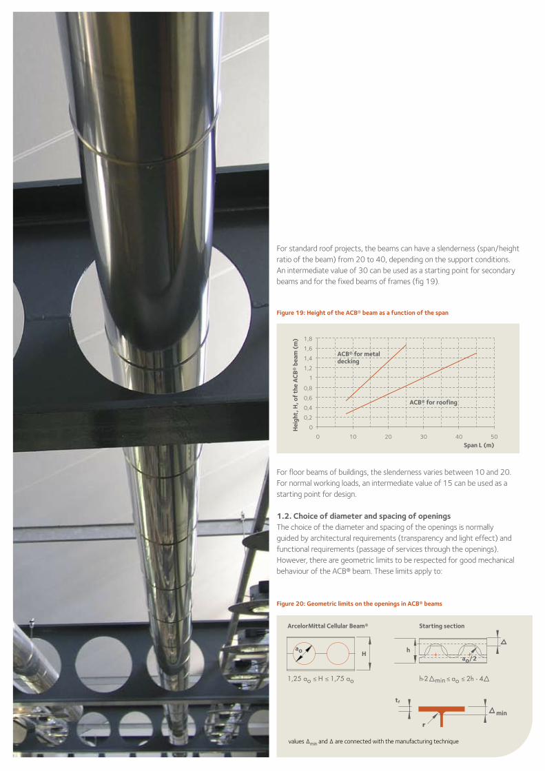
For standard roof projects, the beams can have a slenderness (span/height ratio of the beam) from 20 to 40, depending on the support conditions. An intermediate value of 30 can be used as a starting point for secondary beams and for the fixed beams of frames (fig 19).
For floor beams of buildings, the slenderness varies between 10 and 20. For normal working loads, an intermediate value of 15 can be used as a starting point for design.
1.2. Choice of diameter and spacing of openings The choice of the diameter and spacing of the openings is normally guided by architectural requirements (transparency and light effect) and functional requirements (passage of services through the openings). However, there are geometric limits to be respected for good mechanical behaviour of the ACB® beam. These limits apply to:
Figure 20: Geometric limits on the openings in ACB® beams
ao H h
min
min
ao/2
tf
r
values ∆min and ∆ are connected with the manufacturing technique
Figure 19: Height of the ACB® beam as a function of the span
0
0,2
0,4
0,6
0,8
1
1,2
1,4
1,6
1,8
0 10 20 30 40 50
Hei
ght,
H, o
f th
e A
CB
® be
am (
m)
ACB® for metal decking
ACB® for roofing
Span L (m)
Starting sectionArcelorMittal Cellular Beam®
17
W
W
H
ACB®
ao
Hao
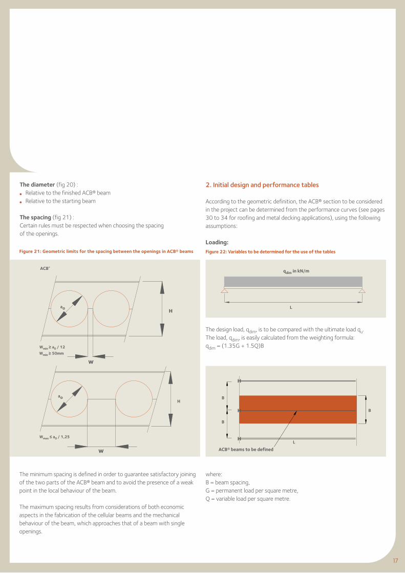
Figure 21: Geometric limits for the spacing between the openings in ACB® beams
The diameter (fig 20) :l Relative to the finished ACB® beaml Relative to the starting beam
The spacing (fig 21) : Certain rules must be respected when choosing the spacing of the openings.
The minimum spacing is defined in order to guarantee satisfactory joining of the two parts of the ACB® beam and to avoid the presence of a weak point in the local behaviour of the beam.
The maximum spacing results from considerations of both economic aspects in the fabrication of the cellular beams and the mechanical behaviour of the beam, which approaches that of a beam with single openings.
2. Initial design and performance tables
According to the geometric definition, the ACB® section to be considered in the project can be determined from the performance curves (see pages 30 to 34 for roofing and metal decking applications), using the following assumptions:
Loading:
Figure 22: Variables to be determined for the use of the tables
B
B
B
L
L
The design load, qdim, is to be compared with the ultimate load qu. The load, qdim, is easily calculated from the weighting formula: qdim = (1.35G + 1.5Q)B
where:B = beam spacing,G = permanent load per square metre,Q = variable load per square metre.
qdim in kN/m
ACB® beams to be defined
Wmin ≥ a0 / 12
Wmin ≥ 50mm
Wmax ≤ a0 / 1,25
L
qSLS
Deflecion
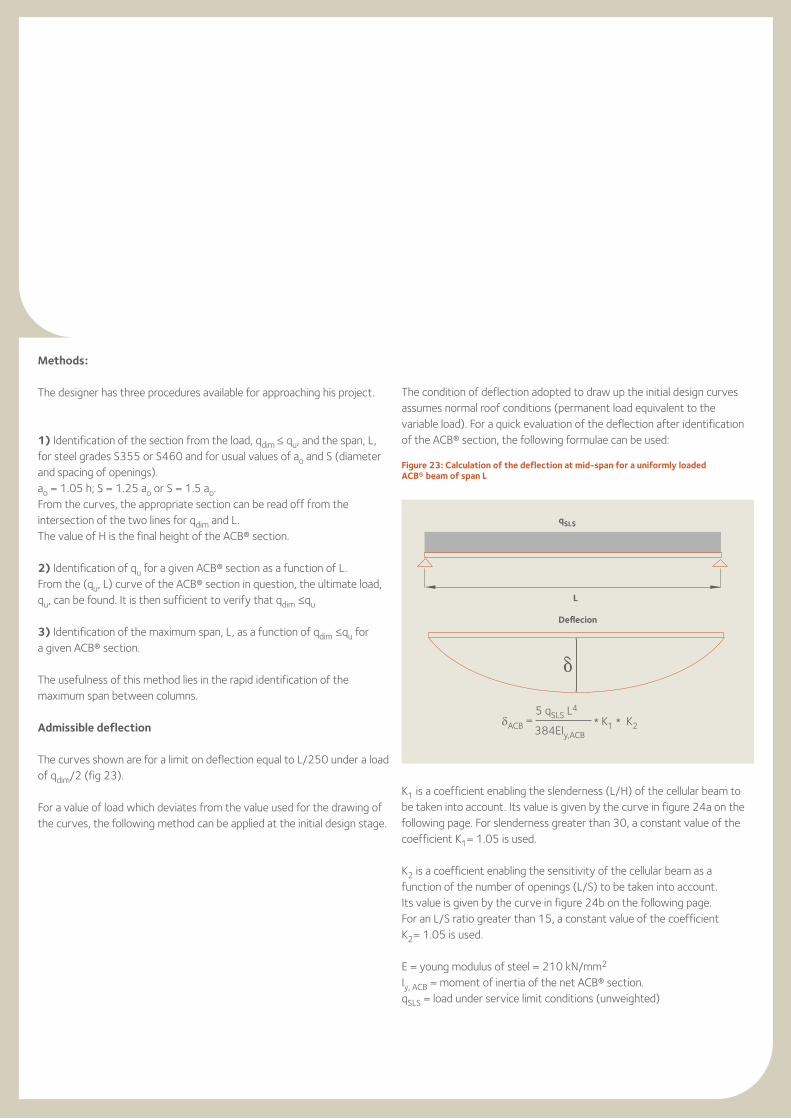
Methods:
The designer has three procedures available for approaching his project.
1) Identification of the section from the load, qdim ≤ qu, and the span, L, for steel grades S355 or S460 and for usual values of ao and S (diameter and spacing of openings).ao = 1.05 h; S = 1.25 ao or S = 1.5 ao.From the curves, the appropriate section can be read off from the intersection of the two lines for qdim and L.The value of H is the final height of the ACB® section.
2) Identification of qu for a given ACB® section as a function of L.From the (qu, L) curve of the ACB® section in question, the ultimate load, qu, can be found. It is then sufficient to verify that qdim ≤qu
3) Identification of the maximum span, L, as a function of qdim ≤qu for a given ACB® section.
The usefulness of this method lies in the rapid identification of the maximum span between columns.
Admissible deflection
The curves shown are for a limit on deflection equal to L/250 under a load of qdim/2 (fig 23).
For a value of load which deviates from the value used for the drawing of the curves, the following method can be applied at the initial design stage.
The condition of deflection adopted to draw up the initial design curves assumes normal roof conditions (permanent load equivalent to the variable load). For a quick evaluation of the deflection after identification of the ACB® section, the following formulae can be used:
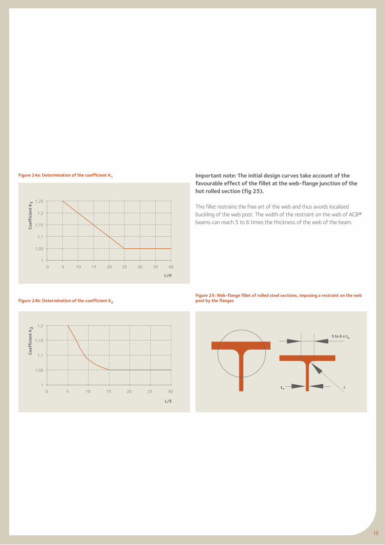
K1 is a coefficient enabling the slenderness (L/H) of the cellular beam to be taken into account. Its value is given by the curve in figure 24a on the following page. For slenderness greater than 30, a constant value of the coefficient K1= 1.05 is used.
K2 is a coefficient enabling the sensitivity of the cellular beam as a function of the number of openings (L/S) to be taken into account. Its value is given by the curve in figure 24b on the following page. For an L/S ratio greater than 15, a constant value of the coefficient K2= 1.05 is used.
E = young modulus of steel = 210 kN/mm2 Iy, ACB = moment of inertia of the net ACB® section.qSLS = load under service limit conditions (unweighted)
Figure 23: Calculation of the deflection at mid-span for a uniformly loaded ACB® beam of span L
δACB = 5 qSLS L4
* K1 * K2 384EIy,ACB
19
Important note: The initial design curves take account of the favourable effect of the fillet at the web-flange junction of the hot rolled section (fig 25). This fillet restrains the free art of the web and thus avoids localised buckling of the web post. The width of the restraint on the web of ACB® beams can reach 5 to 6 times the thickness of the web of the beam.
Figure 24a: Determination of the coefficient K1
Figure 24b: Determination of the coefficient K2
Coe
ffic
ient
K2
1
1,05
1,1
1,15
1,2
0 5 10 15 20 25 30
L/S
1
1,05
1,1
1,15
1,2
1,25
0 5 10 15 20 25 30 35 40
Coe
ffic
ient
K1
L/H
rtw
Figure 25: Web-flange fillet of rolled steel sections, imposing a restraint on the web post by the flanges
5 to 6 x tw
21
6. Asymmetric cellular beams in composite floor application
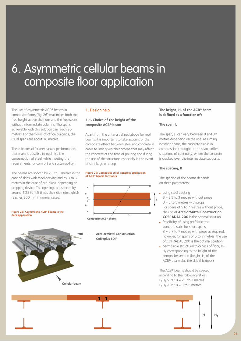
The use of asymmetric ACB® beams in composite floors (fig. 26) maximises both the free height above the floor and the free spans without intermediate columns. The spans achievable with this solution can reach 30 metres. For the floors of office buildings, the usual spans are about 18 metres.
These beams offer mechanical performances that make it possible to optimise the consumption of steel, while meeting the requirements for comfort and sustainability.
The beams are spaced by 2.5 to 3 metres in the case of slabs with steel decking and by 3 to 6 metres in the case of pre-slabs, depending on propping device. The openings are spaced by around 1.25 to 1.5 times their diameter, which reaches 300 mm in normal cases.
Figure 26: Asymmetric ACB® beams in the deck application
1. Design help
1.1. Choice of the height of the composite ACB® beam
Apart from the criteria defined above for roof beams, it is important to take account of the composite effect between steel and concrete in order to limit given phenomena that may affect the concrete at the time of pouring and during the use of the structure, especially in the event of shrinkage or creep.
The height, H, of the ACB® beam is defined as a function of:
The span, L
The span, L, can vary between 8 and 30 metres depending on the use. Assuming isostatic spans, the concrete slab is in compression throughout the span, unlike situations of continuity, where the concrete is cracked over the intermediate supports.
The spacing, B
The spacing of the beams depends on three parameters:
l using steel decking B = 2.5 to 3 metres without props
B = 3 to 5 metres with props For spans of 5 to 7 metres without props,
the use of ArcelorMittal Construction COFRADAL 200 is the optimal solution.
l Possibility of using prefabricated concrete slabs for short spans
B = 2.7 to 7 metres with props as required, however, for spans of 5 to 7 metres, the use of COFRADAL 200 is the optimal solution
l permissible structural thickness of floor, HT HT corresponding to the height of the
composite section (height, H, of the ACB® beam plus the slab thickness)
The ACB® beams should be spaced according to the following ratios: L/HT > 20: B = 2.5 to 3 metres L/HT < 15: B = 3 to 5 metres
Figure 27: Composite steel-concrete application of ACB® beams for floors
B
B
B
L
Cellular beam
Composite ACB® beams
ArcelorMittal Construction
Cofraplus 60 P
H HT
0
0,2
0,4
0,6
0,8
1
1,2
1,4
0 5 10 15 20 25 30 35
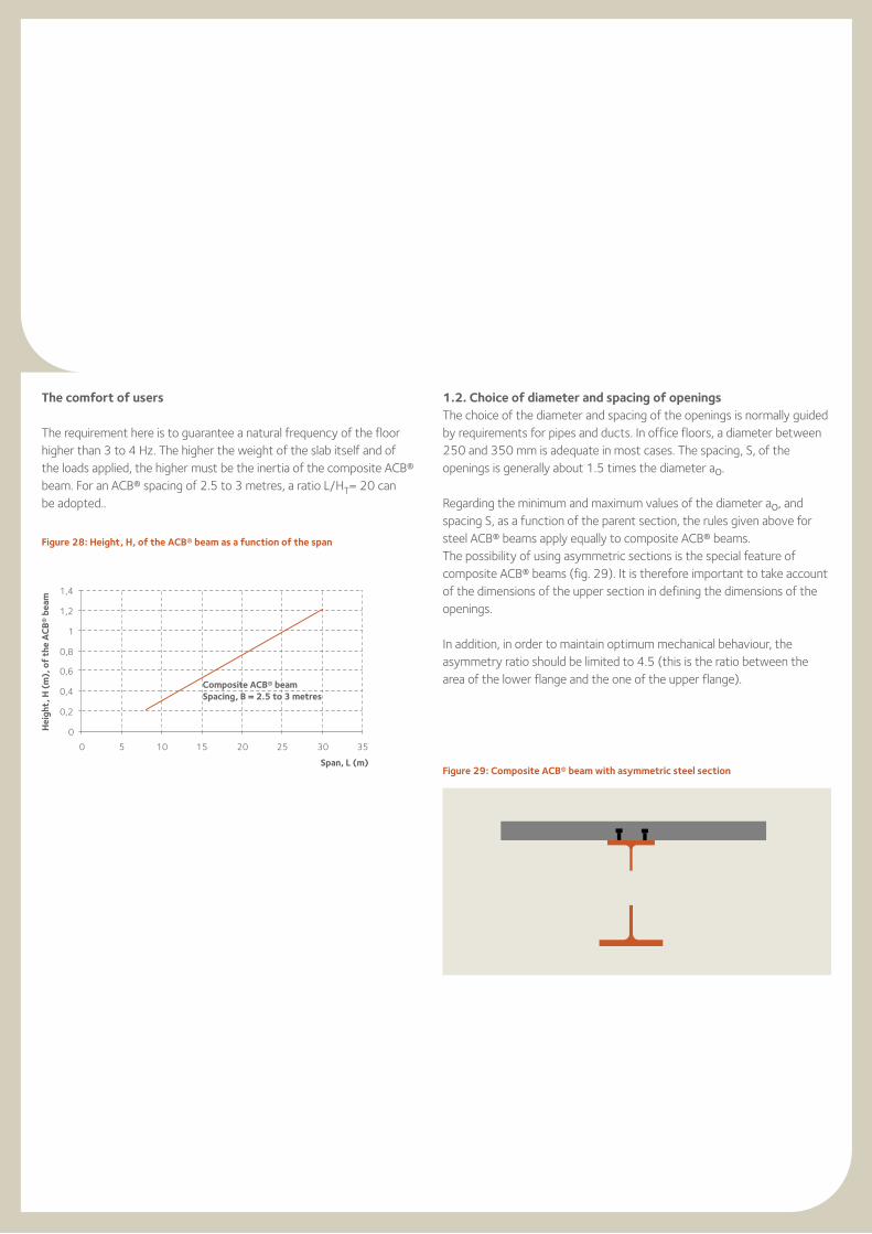
The comfort of users
The requirement here is to guarantee a natural frequency of the floor higher than 3 to 4 Hz. The higher the weight of the slab itself and of the loads applied, the higher must be the inertia of the composite ACB® beam. For an ACB® spacing of 2.5 to 3 metres, a ratio L/HT= 20 can be adopted..
1.2. Choice of diameter and spacing of openingsThe choice of the diameter and spacing of the openings is normally guided by requirements for pipes and ducts. In office floors, a diameter between 250 and 350 mm is adequate in most cases. The spacing, S, of the openings is generally about 1.5 times the diameter ao.
Regarding the minimum and maximum values of the diameter ao, and spacing S, as a function of the parent section, the rules given above for steel ACB® beams apply equally to composite ACB® beams. The possibility of using asymmetric sections is the special feature of composite ACB® beams (fig. 29). It is therefore important to take account of the dimensions of the upper section in defining the dimensions of the openings.
In addition, in order to maintain optimum mechanical behaviour, the asymmetry ratio should be limited to 4.5 (this is the ratio between the area of the lower flange and the one of the upper flange).
Figure 28: Height, H, of the ACB® beam as a function of the span
Hei
ght,
H (
m),
of
the
AC
B®
beam
Composite ACB® beamSpacing, B = 2.5 to 3 metres
Span, L (m)Figure 29: Composite ACB® beam with asymmetric steel section
where:B = beam spacing,G = permanent load per square metre,Q = variable load per square metre.
2. Initial design and performance tables
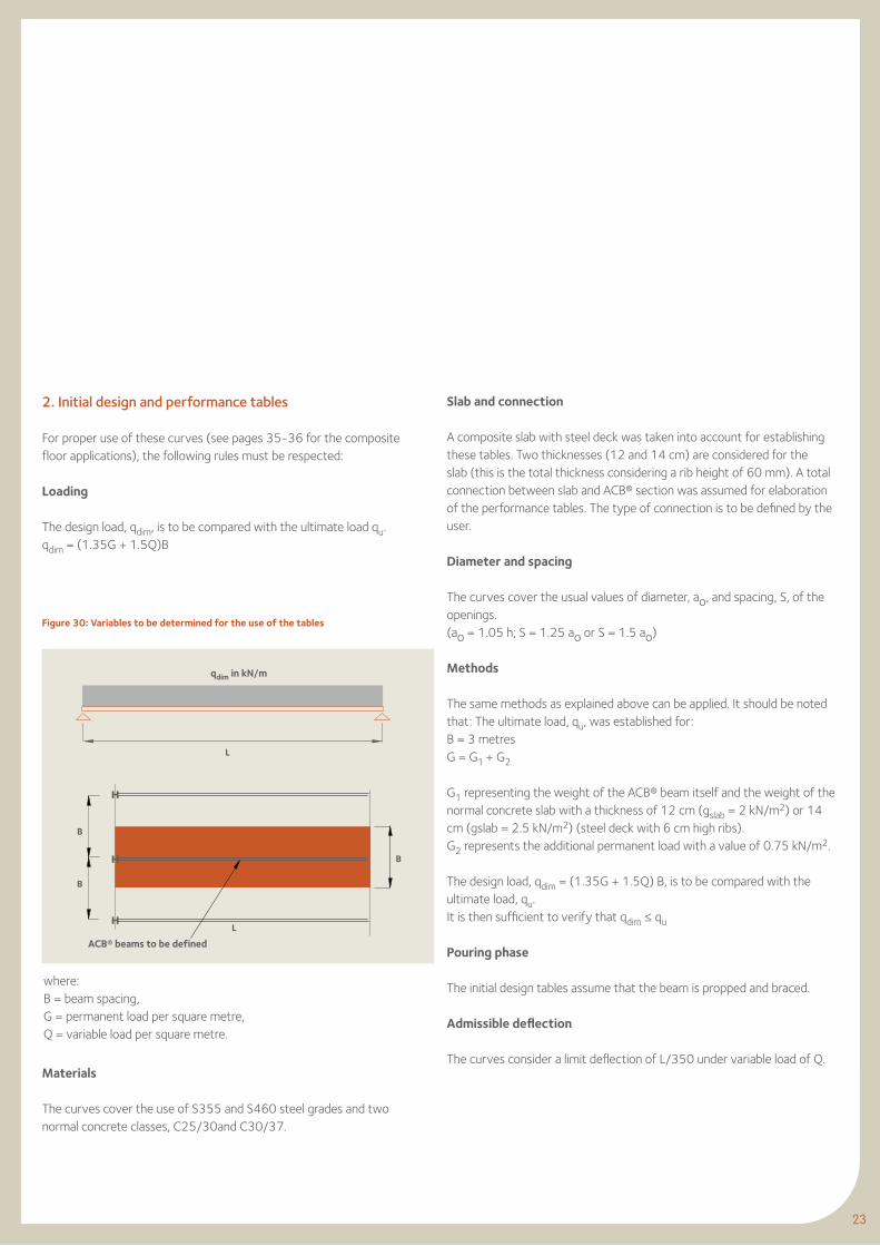
For proper use of these curves (see pages 35-36 for the composite floor applications), the following rules must be respected:
Loading
The design load, qdim, is to be compared with the ultimate load qu. qdim = (1.35G + 1.5Q)B
Figure 30: Variables to be determined for the use of the tables
B
B
B
L
L
Materials
The curves cover the use of S355 and S460 steel grades and two normal concrete classes, C25/30and C30/37.
23
Slab and connection
A composite slab with steel deck was taken into account for establishing these tables. Two thicknesses (12 and 14 cm) are considered for the slab (this is the total thickness considering a rib height of 60 mm). A total connection between slab and ACB® section was assumed for elaboration of the performance tables. The type of connection is to be defined by the user.
Diameter and spacing
The curves cover the usual values of diameter, ao, and spacing, S, of the openings.(ao = 1.05 h; S = 1.25 ao or S = 1.5 ao)
Methods
The same methods as explained above can be applied. It should be noted that: The ultimate load, qu, was established for: B = 3 metres G = G1 + G2
G1 representing the weight of the ACB® beam itself and the weight of the normal concrete slab with a thickness of 12 cm (gslab = 2 kN/m2) or 14 cm (gslab = 2.5 kN/m2) (steel deck with 6 cm high ribs). G2 represents the additional permanent load with a value of 0.75 kN/m2.
The design load, qdim = (1.35G + 1.5Q) B, is to be compared with the ultimate load, qu. It is then sufficient to verify that qdim ≤ qu
Pouring phase
The initial design tables assume that the beam is propped and braced.
Admissible deflection
The curves consider a limit deflection of L/350 under variable load of Q.
qdim in kN/m
ACB® beams to be defined
25
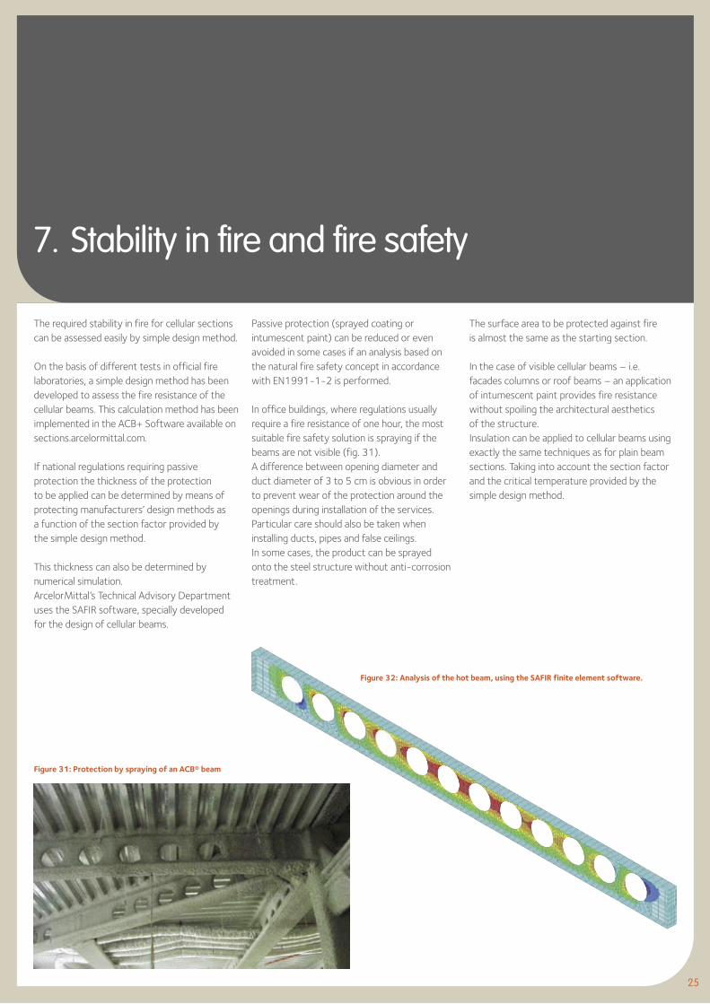
7. Stability in fire and fire safety
The required stability in fire for cellular sections can be assessed easily by simple design method.
On the basis of different tests in official fire laboratories, a simple design method has been developed to assess the fire resistance of the cellular beams. This calculation method has been implemented in the ACB+ Software available on sections.arcelormittal.com.
If national regulations requiring passive protection the thickness of the protection to be applied can be determined by means of protecting manufacturers’ design methods as a function of the section factor provided by the simple design method.
This thickness can also be determined by numerical simulation.ArcelorMittal’s Technical Advisory Department uses the SAFIR software, specially developed for the design of cellular beams.
Passive protection (sprayed coating or intumescent paint) can be reduced or even avoided in some cases if an analysis based on the natural fire safety concept in accordance with EN1991-1-2 is performed.
In office buildings, where regulations usually require a fire resistance of one hour, the most suitable fire safety solution is spraying if the beams are not visible (fig. 31).A difference between opening diameter and duct diameter of 3 to 5 cm is obvious in order to prevent wear of the protection around the openings during installation of the services.Particular care should also be taken when installing ducts, pipes and false ceilings.In some cases, the product can be sprayed onto the steel structure without anti-corrosion treatment.
Figure 31: Protection by spraying of an ACB® beam
Figure 32: Analysis of the hot beam, using the SAFIR finite element software.
The surface area to be protected against fire is almost the same as the starting section.
In the case of visible cellular beams – i.e. facades columns or roof beams – an application of intumescent paint provides fire resistance without spoiling the architectural aesthetics of the structure.Insulation can be applied to cellular beams using exactly the same techniques as for plain beam sections. Taking into account the section factor and the critical temperature provided by the simple design method.
Cit
y of
Lux
embo
urg
adm
inis
trat
ion
build
ing.
Roc
ade
de B
onne
voie
© P
aczo
wsk
i et
Frits
ch a
rchi
tect
es.
27
8. ACB® design charts
The design charts have been drawn up taking account of the characteristic values defined in chapters 5.2 and 6.2.
A full list of the configurations analysed is available on our Website:
.arcelormittal.com
The ACB design charts for roofs and metal decks have been validated by the independent Landesstelle für Bautechnik (state office for building technologies) of the Landesdirektion Leipzig (state directorate Leipzig, Germany).The so-called Typenprüfung allows the specification of ACB beams into projects in Germany instead of other calculation methods (e.g. ACB+ software).The document of the Typenprüfung is available in German on our websitesections.arcelormittal.com (Articles & Publications).
Three categories of charts have been defined
Roofing design charts
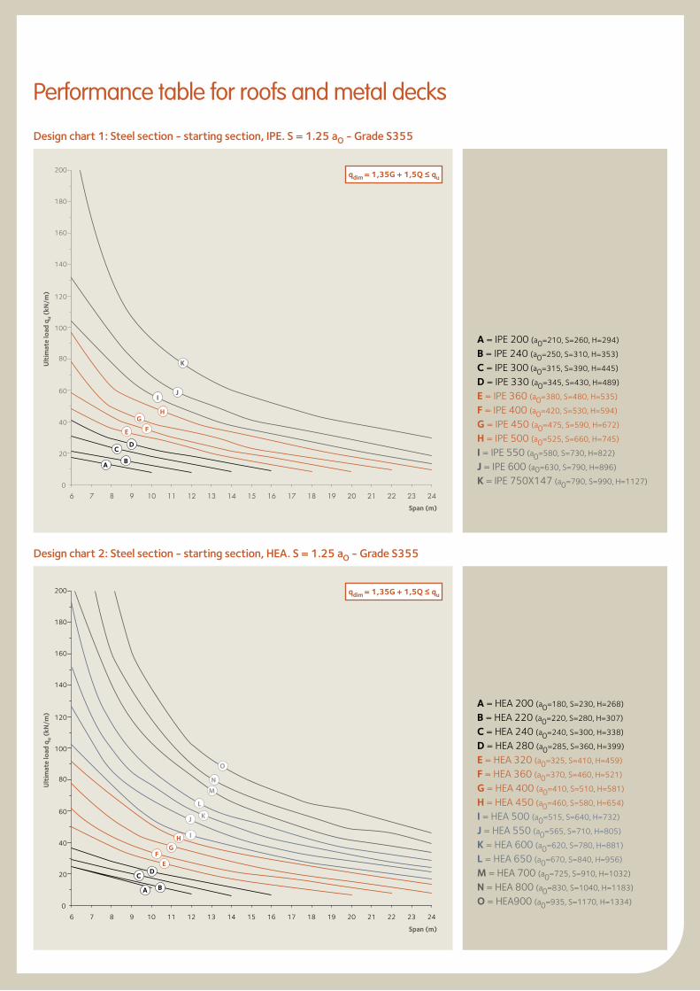
Steel grade S355.For these charts, a spacing width equivalent to S = 1.25 aO is optimum.The starting sections considered are IPE for low loads, HEA for medium loads, HEM for heavy loads and for configurations where a limit must be set on final height.
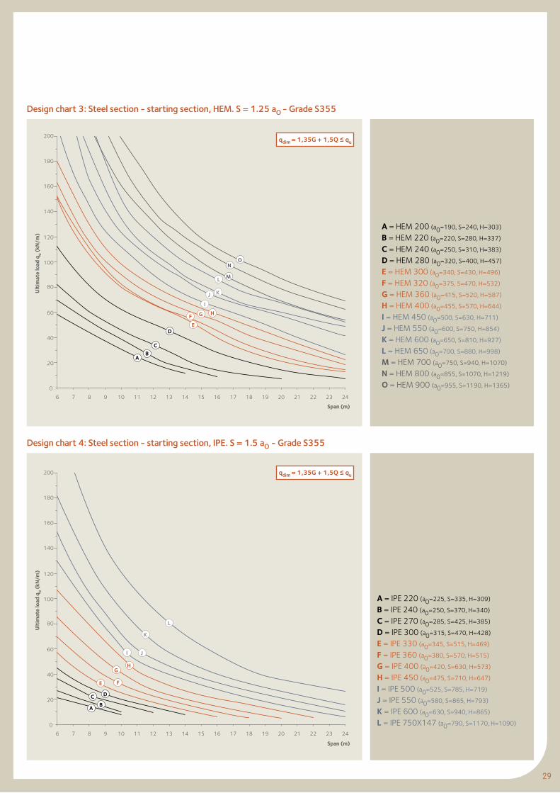
Design charts for metal decks
Steel grades S355 and S460.For these charts, a spacing width equivalent to S = 1.5 aO is optimum.The starting sections considered are IPE for low loads, HEA for medium loads, HEM for heavy loads and for configurations where a limit must beset on final height. Performance table for composite floors
Steel grades S355 and S460.For these charts, a spacing width equivalent to S = 1.5 aO is optimum.The configurations considered depend on the applied loads with asymetric ACB® beams. The starting sections considered are IPE/HEA for low loads and HEA/HEB for high loads and for configuration, where a limit must be sit on final height.
aoH
S
0
20
40
60
80
100
120
140
160
180
200
6 7 8 9 10 11 12 13 14 15 16 17 18 19 20 21 22 23 24
A B
CD
L
M
N
O
J
GH
EF
I
K
0
20
40
60
80
100
120
140
160
180
200
6 7 8 9 10 11 12 13 14 15 16 17 18 19 20 21 22 23 24
A B
C
E F
K
IJ
H
D
G
Design chart 1: Steel section - starting section, IPE. S = 1.25 aO - Grade S355
Design chart 2: Steel section - starting section, HEA. S = 1.25 aO - Grade S355
A = IPE 200 (a0=210, S=260, H=294)
B = IPE 240 (a0=250, S=310, H=353)
C = IPE 300 (a0=315, S=390, H=445)
D = IPE 330 (a0=345, S=430, H=489)
E = IPE 360 (a0=380, S=480, H=535)
F = IPE 400 (a0=420, S=530, H=594)
G = IPE 450 (a0=475, S=590, H=672)
H = IPE 500 (a0=525, S=660, H=745)
I = IPE 550 (a0=580, S=730, H=822)
J = IPE 600 (a0=630, S=790, H=896)
K = IPE 750X147 (a0=790, S=990, H=1127)
A = HEA 200 (a0=180, S=230, H=268)
B = HEA 220 (a0=220, S=280, H=307)
C = HEA 240 (a0=240, S=300, H=338)
D = HEA 280 (a0=285, S=360, H=399)
E = HEA 320 (a0=325, S=410, H=459)
F = HEA 360 (a0=370, S=460, H=521)
G = HEA 400 (a0=410, S=510, H=581)
H = HEA 450 (a0=460, S=580, H=654)
I = HEA 500 (a0=515, S=640, H=732)
J = HEA 550 (a0=565, S=710, H=805)
K = HEA 600 (a0=620, S=780, H=881)
L = HEA 650 (a0=670, S=840, H=956)
M = HEA 700 (a0=725, S=910, H=1032)
N = HEA 800 (a0=830, S=1040, H=1183)
O = HEA900 (a0=935, S=1170, H=1334)
qdim = 1,35G + 1,5Q ≤ qu
qdim = 1,35G + 1,5Q ≤ qu
Performance table for roofs and metal decks
Ult
imat
e lo
ad q
u (k
N/m
)
Span (m)
Ult
imat
e lo
ad q
u (k
N/m
)
Span (m)
29
0
20
40
60
80
100
120
140
160
180
200
6 7 8 9 10 11 12 13 14 15 16 17 18 19 20 21 22 23 24
AB
C
D
L M
NO
I
J K
E
F HG
Design chart 3: Steel section - starting section, HEM. S = 1.25 aO - Grade S355
Design chart 4: Steel section - starting section, IPE. S = 1.5 aO - Grade S355
A = HEM 200 (a0=190, S=240, H=303)
B = HEM 220 (a0=220, S=280, H=337)
C = HEM 240 (a0=250, S=310, H=383)
D = HEM 280 (a0=320, S=400, H=457)
E = HEM 300 (a0=340, S=430, H=496)
F = HEM 320 (a0=375, S=470, H=532)
G = HEM 360 (a0=415, S=520, H=587)
H = HEM 400 (a0=455, S=570, H=644)
I = HEM 450 (a0=500, S=630, H=711)
J = HEM 550 (a0=600, S=750, H=854)
K = HEM 600 (a0=650, S=810, H=927)
L = HEM 650 (a0=700, S=880, H=998)
M = HEM 700 (a0=750, S=940, H=1070)
N = HEM 800 (a0=855, S=1070, H=1219)
O = HEM 900 (a0=955, S=1190, H=1365)
qdim = 1,35G + 1,5Q ≤ qu
qdim = 1,35G + 1,5Q ≤ qu
A = IPE 220 (a0=225, S=335, H=309)
B = IPE 240 (a0=250, S=370, H=340)
C = IPE 270 (a0=285, S=425, H=385)
D = IPE 300 (a0=315, S=470, H=428)
E = IPE 330 (a0=345, S=515, H=469)
F = IPE 360 (a0=380, S=570, H=515)
G = IPE 400 (a0=420, S=630, H=573)
H = IPE 450 (a0=475, S=710, H=647)
I = IPE 500 (a0=525, S=785, H=719)
J = IPE 550 (a0=580, S=865, H=793)
K = IPE 600 (a0=630, S=940, H=865)
L = IPE 750X147 (a0=790, S=1170, H=1090)0
20
40
60
80
100
120
140
160
180
200
6 7 8 9 10 11 12 13 14 15 16 17 18 19 20 21 22 23 24
A BC D
I J
K
L
HG
FE
Ult
imat
e lo
ad q
u (k
N/m
)
Span (m)
Ult
imat
e lo
ad q
u (k
N/m
)
Span (m)
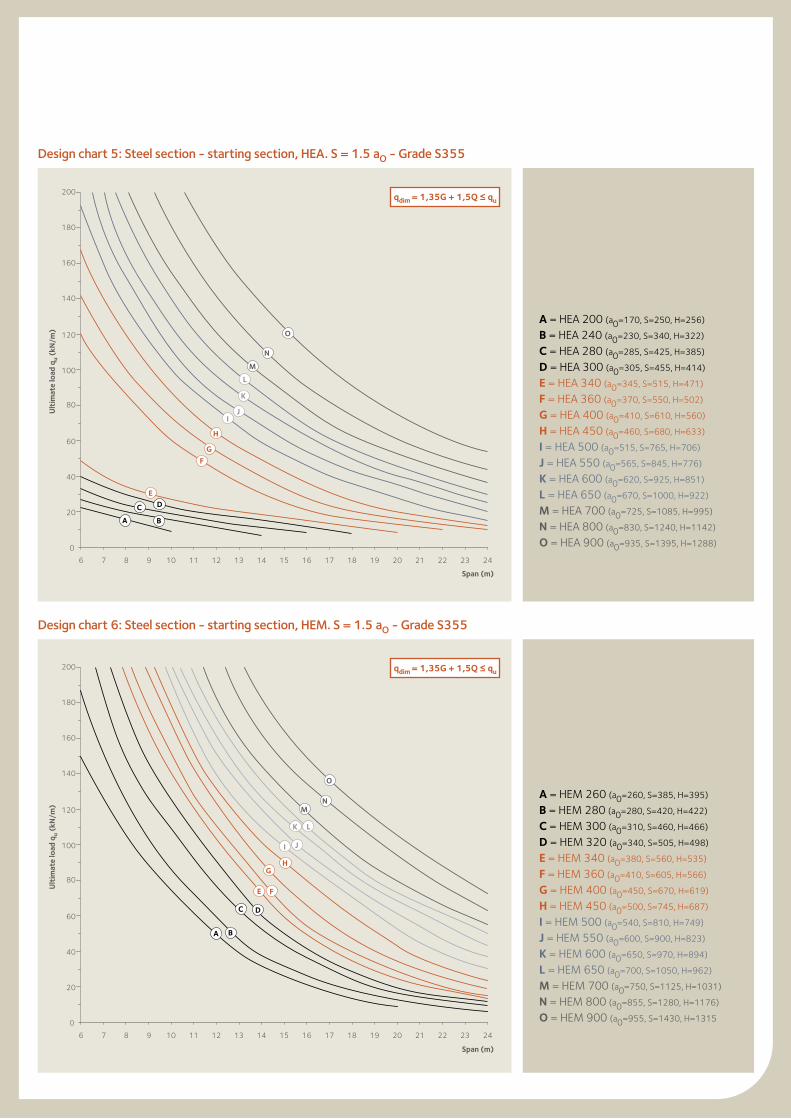
Design chart 5: Steel section - starting section, HEA. S = 1.5 aO - Grade S355
Design chart 6: Steel section - starting section, HEM. S = 1.5 aO - Grade S355
0
20
40
60
80
100
120
140
160
180
200
6 7 8 9 10 11 12 13 14 15 16 17 18 19 20 21 22 23 24
A B
C DE
F
G
H
M
N
O
L
IJ
K
0
20
40
60
80
100
120
140
160
180
200
6 7 8 9 10 11 12 13 14 15 16 17 18 19 20 21 22 23 24
A B
C D
E F
GH
I J
K L
MN
O
A = HEA 200 (a0=170, S=250, H=256)
B = HEA 240 (a0=230, S=340, H=322)
C = HEA 280 (a0=285, S=425, H=385)
D = HEA 300 (a0=305, S=455, H=414)
E = HEA 340 (a0=345, S=515, H=471)
F = HEA 360 (a0=370, S=550, H=502)
G = HEA 400 (a0=410, S=610, H=560)
H = HEA 450 (a0=460, S=680, H=633)
I = HEA 500 (a0=515, S=765, H=706)
J = HEA 550 (a0=565, S=845, H=776)
K = HEA 600 (a0=620, S=925, H=851)
L = HEA 650 (a0=670, S=1000, H=922)
M = HEA 700 (a0=725, S=1085, H=995)
N = HEA 800 (a0=830, S=1240, H=1142)
O = HEA 900 (a0=935, S=1395, H=1288)
A = HEM 260 (a0=260, S=385, H=395)
B = HEM 280 (a0=280, S=420, H=422)
C = HEM 300 (a0=310, S=460, H=466)
D = HEM 320 (a0=340, S=505, H=498)
E = HEM 340 (a0=380, S=560, H=535)
F = HEM 360 (a0=410, S=605, H=566)
G = HEM 400 (a0=450, S=670, H=619)
H = HEM 450 (a0=500, S=745, H=687)
I = HEM 500 (a0=540, S=810, H=749)
J = HEM 550 (a0=600, S=900, H=823)
K = HEM 600 (a0=650, S=970, H=894)
L = HEM 650 (a0=700, S=1050, H=962)
M = HEM 700 (a0=750, S=1125, H=1031)
N = HEM 800 (a0=855, S=1280, H=1176)
O = HEM 900 (a0=955, S=1430, H=1315
qdim = 1,35G + 1,5Q ≤ qu
qdim = 1,35G + 1,5Q ≤ qu
Ult
imat
e lo
ad q
u (k
N/m
)
Span (m)
Ult
imat
e lo
ad q
u (k
N/m
)
Span (m)
31
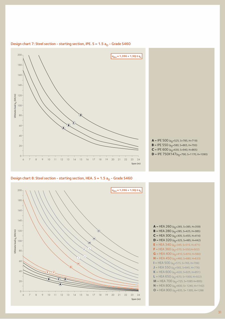
Design chart 7: Steel section - starting section, IPE. S = 1.5 aO - Grade S460
Design chart 8: Steel section - starting section, HEA. S = 1.5 aO - Grade S460
0
20
40
60
80
100
120
140
160
180
200
6 7 8 9 10 11 12 13 14 15 16 17 18 19 20 21 22 23 24
AB
C
D
0
20
40
60
80
100
120
140
160
180
200
6 7 8 9 10 11 12 13 14 15 16 17 18 19 20 21 22 23 24
A
B C D
FE
GH
I J
K L
M
N
O
A = IPE 500 (a0=525, S=785, H=719)
B = IPE 550 (a0=580, S=865, H=793)
C = IPE 600 (a0=630, S=940, H=865)
D = IPE 750X147(a0=790, S=1170, H=1090)
A = HEA 260 (a0=265, S=385, H=359)
B = HEA 280 (a0=285, S=425, H=385)
C = HEA 300 (a0=305, S=455, H=414)
D = HEA 320 (a0=325, S=485, H=442)
E = HEA 340 (a0=345, S=515, H=471)
F = HEA 360 (a0=370, S=550,H=502)
G = HEA 400 (a0=410, S=610, H=560)
H = HEA 450 (a0=460, S=680, H=633)
I = HEA 500 (a0=515, S=765, H=706)
J = HEA 550 (a0=565, S=845, H=776)
K = HEA 600 (a0=620, S=925, H=851)
L = HEA 650 (a0=670, S=1000, H=922)
M = HEA 700 (a0=725, S=1085 H=995)
N = HEA 800 (a0=830, S= 1240, H=1142)
O = HEA 900 (a0=935, S= 1395, H=1288
qdim = 1,35G + 1,5Q ≤ qu
qdim = 1,35G + 1,5Q ≤ qu
Ult
imat
e lo
ad q
u (k
N/m
)
Span (m)
Ult
imat
e lo
ad q
u (k
N/m
)
Span (m)
0
20
40
60
80
100
120
140
160
180
200
6 7 8 9 10 11 12 13 14 15 16 17 18 19 20 21 22 23 24
A B
C D
EF
GH
IJ
K L
M
N
O
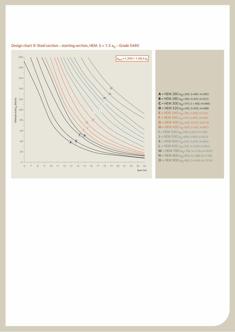
Design chart 9: Steel section - starting section, HEM. S = 1.5 aO - Grade S460
A = HEM 260 (a0=260, S=385, H=395)
B = HEM 280 (a0=280, S=420, H=422)
C = HEM 300 (a0=310, S = 460, H=466)
D = HEM 320 (a0=340, S=505, H=498)
E = HEM 340 (a0=380, S=560, H=535)
F = HEM 360 (a0=410, S=605, H=566)
G = HEM 400 (a0=450, S=670, H=619)
H = HEM 450 (a0=500, S=745, H=687)
I = HEM 500 (a0=540, S=810, H=749)
J = HEM 550 (a0=600, S=900, H=823)
K = HEM 600 (a0=650, S=970, H=894)
L = HEM 650 (a0=700, S=1050, H=962)
M = HEM 700 (a0=750, S=1125, H=1031)
N = HEM 800 (a0=855, S=1280, H=1176)
O = HEM 900 (a0=955, S=1430, H=1315)
qdim = 1,35G + 1,5Q ≤ qu
Ult
imat
e lo
ad q
u (k
N/m
)
Span (m)
33
0
20
40
60
80
100
120
140
160
180
200
6 7 8 9 10 11 12 13 14 15 16 17 18 19 20 21 22 23 24
A BC
D
E
F
I G
J
H
K
0
20
40
60
80
100
120
140
160
180
200
6 7 8 9 10 11 12 13 14 15 16 17 18 19 20 21 22 23 24
A B
C D
E F
G
H
I
JK L
M
N
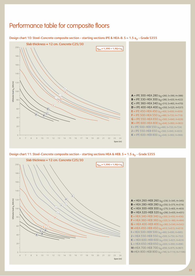
Design chart 10: Steel-Concrete composite section - starting sections IPE & HEA-B. S = 1.5 aO - Grade S355
Design chart 11: Steel-Concrete composite section - starting sections HEA & HEB. S = 1.5 aO - Grade S355
Slab thickness = 12 cm. Concrete C25/30
Slab thickness = 12 cm. Concrete C25/30
A = IPE 300-HEA 280 (a0=260, S=390, H=388)
B = IPE 330-HEA 300 (a0=280, S=420, H=422)
C = IPE 360-HEA 340 (a0=310, S=465, H=470)
D = IPE 400-HEA 400 (a0=350, S=525, H=537)
E = IPE 450-HEA 450 (a0=400, S=600, H=609)
F = IPE 500-HEA 550 (a0=480, S=720, H=719)
G = IPE 550-HEA 650 (a0=560, S=840, H=828)
H = IPE 600-HEA 800 (a0=640, S=960, H=963)
I = IPE 500-HEB 550 (a0=480, S=720, H=724)
J = IPE 550-HEB 650 (a0=560, S=840, H=833)
K = IPE 600-HEB 800 (a0=640, S=960, H=968)
A = HEA 260-HEB 260 (a0=230, S=345, H=345)
B = HEA 280-HEB 280 (a0=250, S=375, H=374)
C = HEA 300-HEB 300 (a0=270, S=405, H=403)
D = HEA 320-HEB 320 (a0=290, S=435, H=431)
E = HEA 340-HEB 340 (a0=300, S=450, H=456)
F = HEA 360-HEB 360 (a0=320, S= 480, H=484)
G = HEA 400-HEB 400 (a0=360, S=540, H=542)
H =HEA 450-HEB 450 (a0=410, S=615, H=613)
I = HEA 500-HEB 500 (a0=460, S=690, H=685)
J = HEA 550-HEB 550 (a0=500, S=750, H=752)
K = HEA 600-HEB 600 (a0=550, S=825, H=824)
L = HEA 650-HEB 650 (a0=600, S=900, H=896)
M=HEA 700-HEB 700 (a0=650, S=975, H=967)
N=HEA 800-HEB 800 (a0=740, S=1110, H=1106)
qdim = 1,35G + 1,5Q ≤ qu
qdim = 1,35G + 1,5Q ≤ qu
Performance table for composite floors
Ult
imat
e lo
ad q
u (k
N/m
)
Span (m)
Ult
imat
e lo
ad q
u (k
N/m
)
Span (m)
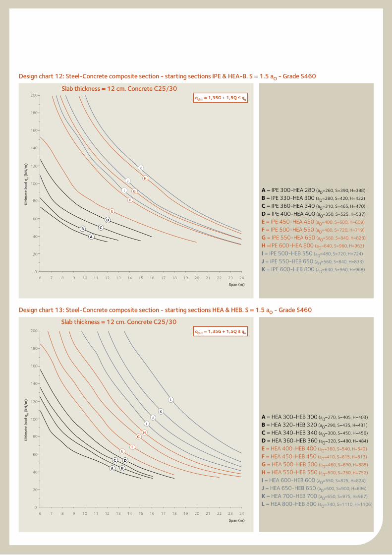
Design chart 12: Steel-Concrete composite section - starting sections IPE & HEA-B. S = 1.5 aO - Grade S460
Design chart 13: Steel-Concrete composite section - starting sections HEA & HEB. S = 1.5 aO - Grade S460
0
20
40
60
80
100
120
140
160
180
200
6 7 8 9 10 11 12 13 14 15 16 17 18 19 20 21 22 23 24
B C
A
D
E
I G
J
K
H
F
0
20
40
60
80
100
120
140
160
180
200
6 7 8 9 10 11 12 13 14 15 16 17 18 19 20 21 22 23 24
A B
C D
EF
GH
I
L
J
K
A = IPE 300-HEA 280 (a0=260, S=390, H=388)
B = IPE 330-HEA 300 (a0=280, S=420, H=422)
C = IPE 360-HEA 340 (a0=310, S=465, H=470)
D = IPE 400-HEA 400 (a0=350, S=525, H=537)
E = IPE 450-HEA 450 (a0=400, S=600, H=609)
F = IPE 500-HEA 550 (a0=480, S=720, H=719)
G = IPE 550-HEA 650 (a0=560, S=840, H=828)
H =IPE 600-HEA 800 (a0=640, S=960, H=963)
I = IPE 500-HEB 550 (a0=480, S=720, H=724)
J = IPE 550-HEB 650 (a0=560, S=840, H=833)
K = IPE 600-HEB 800 (a0=640, S=960, H=968)
A = HEA 300-HEB 300 (a0=270, S=405, H=403)
B = HEA 320-HEB 320 (a0=290, S=435, H=431)
C = HEA 340-HEB 340 (a0=300, S=450, H=456)
D = HEA 360-HEB 360 (a0=320, S=480, H=484)
E = HEA 400-HEB 400 (a0=360, S=540, H=542)
F = HEA 450-HEB 450 (a0=410, S=615, H=613)
G = HEA 500-HEB 500 (a0=460, S=690, H=685)
H = HEA 550-HEB 550 (a0=500, S=750, H=752)
I = HEA 600-HEB 600 (a0=550, S=825, H=824)
J = HEA 650-HEB 650 (a0=600, S=900, H=896)
K = HEA 700-HEB 700 (a0=650, S=975, H=967)
L = HEA 800-HEB 800 (a0=740, S=1110, H=1106)
qdim = 1,35G + 1,5Q ≤ qu
qdim = 1,35G + 1,5Q ≤ qu
Slab thickness = 12 cm. Concrete C25/30
Slab thickness = 12 cm. Concrete C25/30
Ult
imat
e lo
ad q
u (k
N/m
)
Span (m)
Ult
imat
e lo
ad q
u (k
N/m
)
Span (m)
35
9. Design charts: design examples
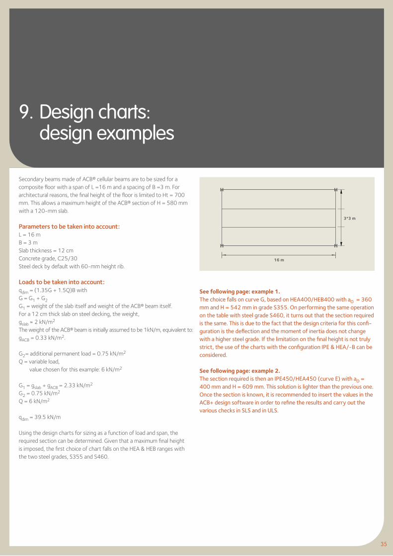
Secondary beams made of ACB® cellular beams are to be sized for a composite floor with a span of L =16 m and a spacing of B =3 m. Forarchitectural reasons, the final height of the floor is limited to Ht = 700 mm. This allows a maximum height of the ACB® section of H = 580 mm with a 120-mm slab.
Parameters to be taken into account:L = 16 mB = 3 mSlab thickness = 12 cmConcrete grade, C25/30Steel deck by default with 60-mm height rib.
Loads to be taken into account:qdim = (1.35G + 1.5Q)B withG = G1 + G2G1 = weight of the slab itself and weight of the ACB® beam itself.For a 12 cm thick slab on steel decking, the weight,gslab ≈ 2 kN/m2
The weight of the ACB® beam is initially assumed to be 1kN/m, equivalent to: gACB = 0.33 kN/m2.
G2= additional permanent load = 0.75 kN/m2
Q = variable load, value chosen for this example: 6 kN/m2
G1 = gslab + gACB = 2.33 kN/m2
G2 = 0.75 kN/m2
Q = 6 kN/m2
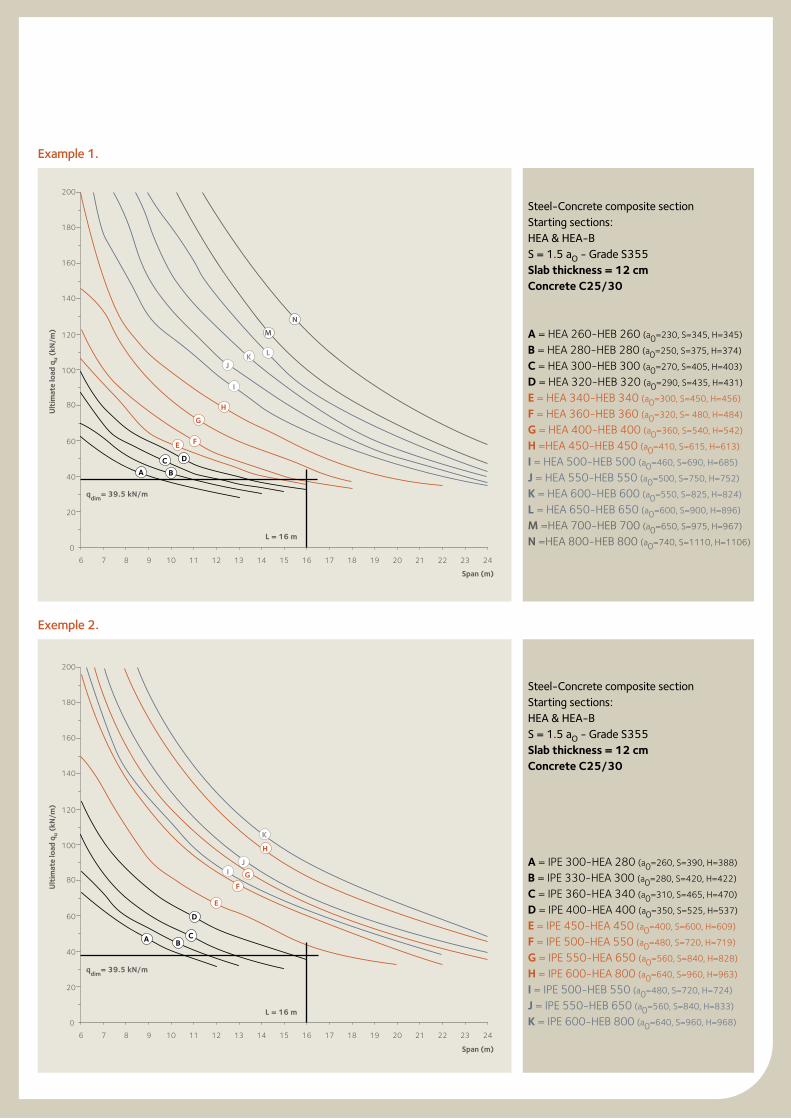
qdim = 39.5 kN/m
Using the design charts for sizing as a function of load and span, the required section can be determined. Given that a maximum final height is imposed, the first choice of chart falls on the HEA & HEB ranges with the two steel grades, S355 and S460.
See following page: example 1.The choice falls on curve G, based on HEA400/HEB400 with aO = 360 mm and H = 542 mm in grade S355. On performing the same operation on the table with steel grade S460, it turns out that the section required is the same. This is due to the fact that the design criteria for this confi-guration is the deflection and the moment of inertia does not change with a higher steel grade. If the limitation on the final height is not truly strict, the use of the charts with the configuration IPE & HEA/-B can be considered.
See following page: example 2.The section required is then an IPE450/HEA450 (curve E) with aO = 400 mm and H = 609 mm. This solution is lighter than the previous one. Once the section is known, it is recommended to insert the values in the ACB+ design software in order to refine the results and carry out the various checks in SLS and in ULS.
3*3 m
16 m
Example 1.
Exemple 2.
Steel-Concrete composite sectionStarting sections:HEA & HEA-BS = 1.5 aO - Grade S355Slab thickness = 12 cmConcrete C25/30
A = HEA 260-HEB 260 (a0=230, S=345, H=345)
B = HEA 280-HEB 280 (a0=250, S=375, H=374)
C = HEA 300-HEB 300 (a0=270, S=405, H=403)
D = HEA 320-HEB 320 (a0=290, S=435, H=431)
E = HEA 340-HEB 340 (a0=300, S=450, H=456)
F = HEA 360-HEB 360 (a0=320, S= 480, H=484)
G = HEA 400-HEB 400 (a0=360, S=540, H=542)
H =HEA 450-HEB 450 (a0=410, S=615, H=613)
I = HEA 500-HEB 500 (a0=460, S=690, H=685)
J = HEA 550-HEB 550 (a0=500, S=750, H=752)
K = HEA 600-HEB 600 (a0=550, S=825, H=824)
L = HEA 650-HEB 650 (a0=600, S=900, H=896)
M =HEA 700-HEB 700 (a0=650, S=975, H=967)
N =HEA 800-HEB 800 (a0=740, S=1110, H=1106)0
20
40
60
80
100
120
140
160
180
200
6 7 8 9 10 11 12 13 14 15 16 17 18 19 20 21 22 23 24
A B
C D
E F
G
H
I
JK L
M
N
qdim
= 39.5 kN/m
L = 16 m
0
20
40
60
80
100
120
140
160
180
200
6 7 8 9 10 11 12 13 14 15 16 17 18 19 20 21 22 23 24
A BC
D
E
F
I G
J
H
K
qdim
= 39.5 kN/m
L = 16 m
Steel-Concrete composite sectionStarting sections:HEA & HEA-BS = 1.5 aO - Grade S355Slab thickness = 12 cmConcrete C25/30
A = IPE 300-HEA 280 (a0=260, S=390, H=388)
B = IPE 330-HEA 300 (a0=280, S=420, H=422)
C = IPE 360-HEA 340 (a0=310, S=465, H=470)
D = IPE 400-HEA 400 (a0=350, S=525, H=537)
E = IPE 450-HEA 450 (a0=400, S=600, H=609)
F = IPE 500-HEA 550 (a0=480, S=720, H=719)
G = IPE 550-HEA 650 (a0=560, S=840, H=828)
H = IPE 600-HEA 800 (a0=640, S=960, H=963)
I = IPE 500-HEB 550 (a0=480, S=720, H=724)
J = IPE 550-HEB 650 (a0=560, S=840, H=833)
K = IPE 600-HEB 800 (a0=640, S=960, H=968)
Ult
imat
e lo
ad q
u (k
N/m
)
Span (m)
Ult
imat
e lo
ad q
u (k
N/m
)
Span (m)
37
10. ACB+ Software
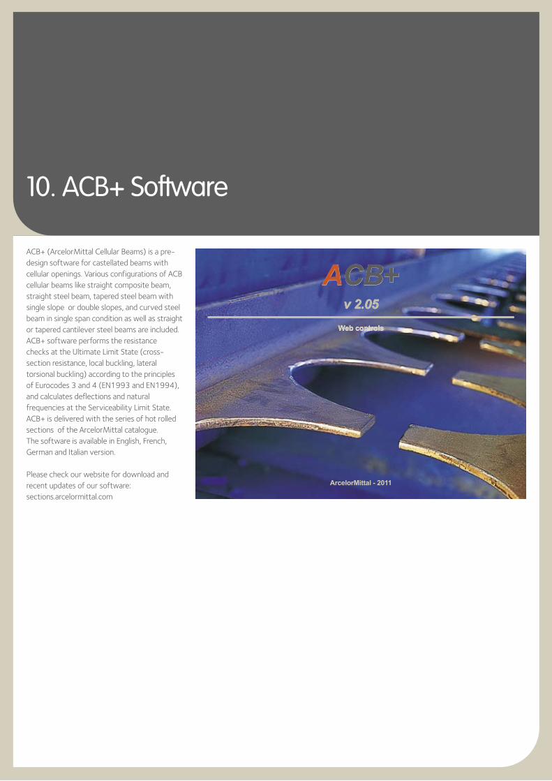
ACB+ (ArcelorMittal Cellular Beams) is a pre-design software for castellated beams with cellular openings. Various configurations of ACB cellular beams like straight composite beam, straight steel beam, tapered steel beam with single slope or double slopes, and curved steel beam in single span condition as well as straight or tapered cantilever steel beams are included. ACB+ software performs the resistance checks at the Ultimate Limit State (cross-section resistance, local buckling, lateral torsional buckling) according to the principles of Eurocodes 3 and 4 (EN1993 and EN1994), and calculates deflections and natural frequencies at the Serviceability Limit State.ACB+ is delivered with the series of hot rolled sections of the ArcelorMittal catalogue. The software is available in English, French, German and Italian version.
Please check our website for download and recent updates of our software: sections.arcelormittal.com
ACB+v 2.05
Web controls
ACB+v 2.05
Web controls
ArcelorMittal - 2011
39
11. ACB® beams: a solution for sustainable development
l Sustainable structures with the use of ACB® beamsThe preservation of natural resources in our industrialized societies has become priority in the creation of the built environment. As a result, construction concepts have to comply with changing economical parameters like the incorporation of life cycle analyses in the design of structures as well as with technological changes in considering sustainability goals in respect to the environment and society.These sustainability goals are in nature:l ecological,l economical,l socio-cultural,l technical oriented,l process oriented.They are interdependent as well as ambivalent, providing a coherent response to complex questions and ensuring future generations a pleasant environment.Sustainable construction using ACB® beams is fully consistent with the various aspects of the three sustainability goals.
l Ecological aspects of sustainabilityThe main ecological goals aim at using building materials that are safe from health and environmental points of view, at reducing building waste when dismantling buildings at the end of their service life, and at preserving as best possible the energy content in the construction materials, thus maintaining their ideal efficiency, Here, structural steels offer high material efficiency and rolled sections constitute the most recycled building material in the world. In the modern electric arc furnace (EAF) route, steel is produced using 100% scrap as a raw material (upcycling). Also, used steel elements can be deployed for further use in renovation and refurbishment of existing buildings.
In addition, the EAF technology allows for significant reductions of noise, particle- and
CO2-emissions as well as water and primary energy consumption in the production mills.
ACB® beams produced by ArcelorMittal allow to integrate all the services within the height of the beam in multi storey buildings and to optimize the cross section by reducing the steel material from the webs. These beams are really environmental friendly, they use a minimum of steel material being slender and lighter. For the straight Cellular Beams, the C02 saving can be estimated at 25% compared to the equivalent solution in plain steel profile.
• EconomicalaspectsofsustainabilityBesides being interested in the reduction of investment costs, investors are also concerned about the optimization of operational costs and the achievement of the longest possible service life in combination with high flexibility in use of the structure.ACB® beams in structures allow architects and designers to easily fulfill the requirements
of investors by combining high quality, functionality, aesthetics, low weight and short construction times. Slender superstructures can be designed which decrease construction height and earthworks leading to a further decrease of material, fabrication, transport and construction costs.
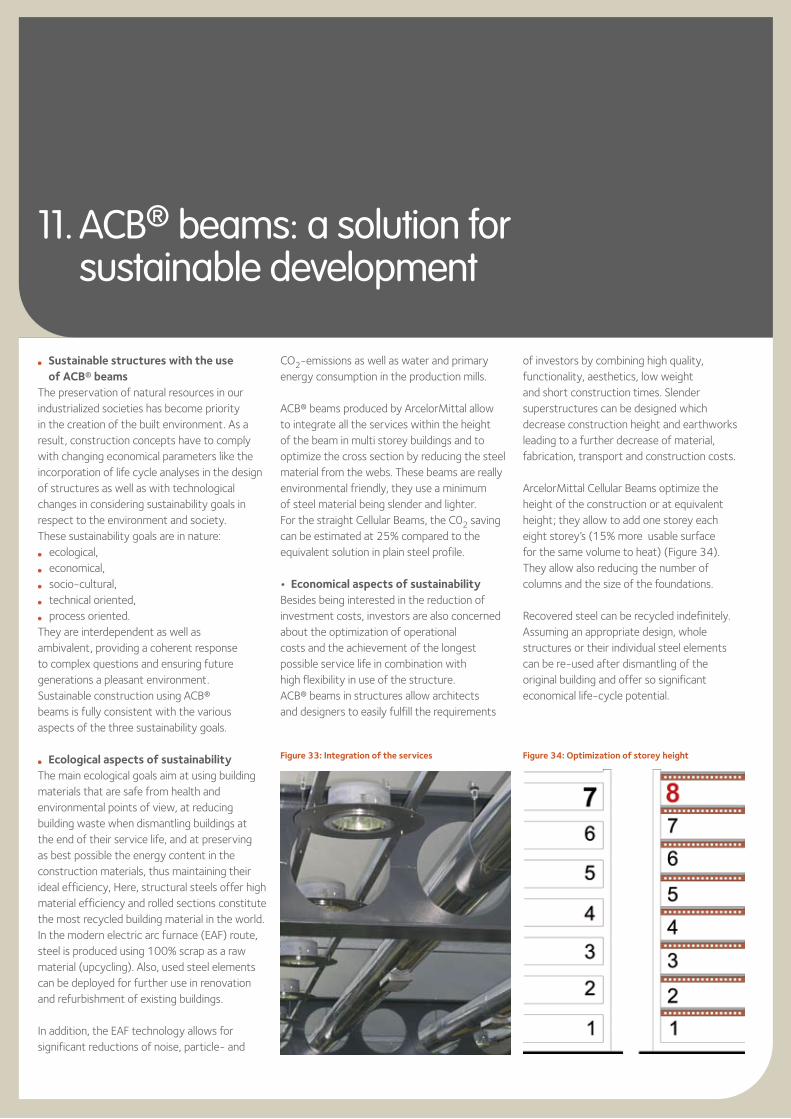
ArcelorMittal Cellular Beams optimize the height of the construction or at equivalent height; they allow to add one storey each eight storey’s (15% more usable surface for the same volume to heat) (Figure 34). They allow also reducing the number of columns and the size of the foundations.
Recovered steel can be recycled indefinitely.Assuming an appropriate design, whole structures or their individual steel elements can be re-used after dismantling of the original building and offer so significant economical life-cycle potential.
Figure 33: Integration of the services Figure 34: Optimization of storey height
l Socio-cultural aspects of sustainabilityThis aspect allows the architect to reconcile his own aesthetic demands for a building with the social expectations of its surrounding environment. Again, thanks to the prefabrication construction system, ACB® beams provide the user with transparent and lean structures combined with robustness and safety. The inhabitants and their social environment live in a clean, uncontaminated surrounding as steel in structures does not release any harmful substances into the environment and represents therefore no danger to living beings.
l Technical aspects of sustainabilityStructures made of ACB® beams have the advantage of being able to resist high level utilization and are adaptable to changes in use. These robust construction solutions are capable of coping well with variations in use during service life without damage or loss of functionality.
l Process aspects of sustainabilitySteel constructions offer many advantages through its flexibility, lightness and cost effectiveness. ACB® beams are used as primary bearing elements. They are industrially produced to a high quality, offer good availability in a full range of sizes and steel grades, including ArcelorMittal’s HISTAR high strength steels. Fabricated in specialized workshops the end product is delivered to site ready for erection. Quality control has already been carried out at the production. Smaller construction sites and plant equipment are therefore needed whilst minimal noise and dust disturbance on site are characteristics for steel construction. Structures using hot rolled sections reduce erection times. Hence, transportation cost as well as accident potential is reduced.
41
12. AngelinaTM Beams Our last born castellated beam
with sinusoidal openings
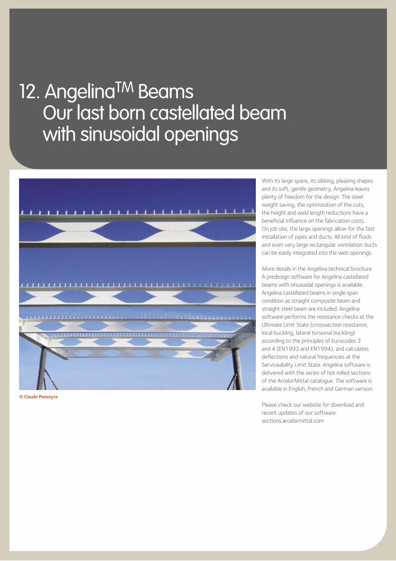
With its large spans, its oblong, pleasing shapes and its soft, gentle geometry, Angelina leaves plenty of freedom for the design. The steel weight saving, the optimization of the cuts, the height and weld length reductions have a beneficial influence on the fabrication costs. On job site, the large openings allow for the fast installation of pipes and ducts. All kind of fluids and even very large rectangular ventilation ducts can be easily integrated into the web openings.
More details in the Angelina technical brochure A predesign software for Angelina castellated beams with sinusoidal openings is available. Angelina castellated beams in single span condition as straight composite beam and straight steel beam are included. Angelina software performs the resistance checks at the Ultimate Limit State (crosssection resistance, local buckling, lateral torsional buckling) according to the principles of Eurocodes 3 and 4 (EN1993 and EN1994), and calculates deflections and natural frequencies at the Serviceability Limit State. Angelina software is delivered with the series of hot rolled sections of the ArcelorMittal catalogue. The software is available in English, French and German version.
Please check our website for download and recent updates of our software:sections.arcelormittal.com
© Claude Penseyre

Notes
43
Klim
ahau
s, B
rem
erha
ven,
© B
EAN
Gm
bH &
Co.
KG

Technical Advisory& Finishing
Finishing
As a complement to the technical capacities of our partners, we are equipped with high-performance finishing tools and offer a wide range of services, such as:
l drillingl flame cuttingl T cut-outsl notchingl camberingl curvingl straighteningl cold sawing to exact lengthl welding and fitting of studsl shot and sand blastingl surface treatment [email protected]
ArcelorMittal has also a website dedicated to a full range of products for the construction market (structures, facades, roofing, etc.):
www.constructalia.com
Your Partners
ArcelorMittal Commercial sections66, rue de LuxembourgL-4221 Esch-sur-AlzetteLuxembourgTel.: +352 5313 3010Fax: +352 5313 [email protected]
sections.arcelormittal.com
We operate in more than 60 countries on all five continents. Please have a look at our website under “About us” to find our local agency in your country.
Technical Advisory
We are happy to provide free technical advice to optimise the use of our products and solutions in your projects and to answer your questions about the use of sections and merchant bars. This technical advice covers the design of structural elements, construction details, surface protection, fire safety, metallurgy and welding.
Our specialists are ready to support your initiatives anywhere in the world.
To facilitate the design of your projects, we also offer free software and technical documentation that you can consult or download from our website:
sections.arcelormittal.com
Although every care has been taken during the production of this brochure, we regret that we cannot accept any liability in respect of any incorrect information it may contain or any damages which may arise through the misinterpretation of its contents.
ArcelorMittalCommercial sections
66, rue de LuxembourgL-4221 Esch-sur-AlzetteLUXEMBOURGTel.: + 352 5313 3010Fax: + 352 5313 2799
sections.arcelormittal.com
Vers
ion
20
14
-1


![SE21 paper-Cellular floors/Long span beams in fire tests ...uir.ulster.ac.uk/20470/1/8772-89-21[structE].pdf · at Cardington in the UK9,10, a simple design method for beams and Paper](https://img.dokumen.tips/doc/110x75/5aa232677f8b9ac67a8ccc3c/se21-paper-cellular-floorslong-span-beams-in-fire-tests-uir-structepdfat.jpg)