Embed Size (px)
Citation preview

Introduction
Thank you for purchasing the ISA 430 MKII brought to youby the Focusrite team – Ian, Trevor, Peter, Martin, Tom,Mick A’C, Phil, Chris G, Micky, Pauline, Melissa, Chris W,Rob J Snr, Simon J, Vernon, Giles, Rob J Jnr, Mick G, Tim,Dave, Paul and Simon.
The chaps at Focusrite are a jolly hard working bunch andtake a great deal of pride in designing, building and deliveringproducts which are considered to be the best audio unitsaround; we hope your new Focusrite unit lives up to thatreputation and that you enjoy many years of productiverecording. If you would like to tell us about your recordingexperiences, please email us at: [email protected]
The Focusrite Team
Contents
Introduction....................................................................................... 1Contents............................................................................................. 1Important Safety Instructions ........................................................ 1Power Connections ......................................................................... 1Rear Panel Connections.................................................................. 2ISA 430 MKII Front Panel Controls ............................................. 3Metering.............................................................................................. 3Input Stage.......................................................................................... 4EQ Module......................................................................................... 5Compressor....................................................................................... 6Gate ..................................................................................................... 8De-Esser ............................................................................................. 9Output ................................................................................................ 9Inserts and Routing Matrix...........................................................10Soft Limiter ......................................................................................13Optional Analogue to Digital Converter (ADC) ....................13Digital Output Front Panel Controls .........................................14ADC Configurations......................................................................15Mic Pre-amp Input Impedance.....................................................16Applications......................................................................................17FAQs .................................................................................................21Specifications ...................................................................................24Accuracy ...........................................................................................26Copyright..........................................................................................26Warranty ..........................................................................................26Reset Sheet ......................................................................................27Focusrite Distributors ...................................................................28
Important Safety Instructions
Please read all of these instructions and save them forfuture reference. Follow all warnings and instructionsmarked on the unit.
• Do not obstruct air vents in the rear panel. Do notinsert objects through any apertures.
• Do not use a damaged or frayed power cord.
• Unplug the unit before cleaning. Clean with a dampcloth only. Do not spill liquid on the unit.
• Unplug the unit and refer servicing to qualified servicepersonnel under the following conditions: if the powercord or plug is damaged; if liquid has entered the unit; ifthe unit has been dropped or the case damaged; if theunit does not operate normally or exhibits a distinctchange in performance. Adjust only those controls thatare covered by the operating instructions.
• Do not defeat the safety purpose of the polarised orgrounding type plug. A polarised plug has two bladeswith one wider than the other. A grounding type plughas two blades and a third grounding prong. The widerblade or the third prong are provided for your safety.When the plug provided does not fit into your outlet,consult an electrician for replacement of the obsoleteoutlet.
WARNING: THIS UNIT MUST BE EARTHEDBY THE POWER CORD.
UNDER NO CIRCUMSTANCES SHOULD THEMAINS EARTH BE DISCONNECTED FROM
THE MAINS LEAD.
This unit is capable of operating over a range of mainsvoltages as marked on the rear panel. Ensure correct mainsvoltage setting and correct fuse before connecting mainssupply. Do not change mains voltage settings while mainssupply is connected. To avoid the risk of fire, replace themains fuse only with the correct value fuse, as marked onthe rear panel. The internal power supply unit contains nouser serviceable parts. Refer all servicing to a qualifiedservice engineer, through the appropriate Focusrite dealer.
Power Connections
There is an IEC mains lead supplied with the unit whichshould have the correct moulded plug for your country.The wiring colour code used is:
For units shipped to the USA, Canada, Taiwan and Japan:Live - Black Neutral - White Earth - Green
For units shipped to any other country:Live - Brown Neutral - Blue Earth - Green and Yellow
1
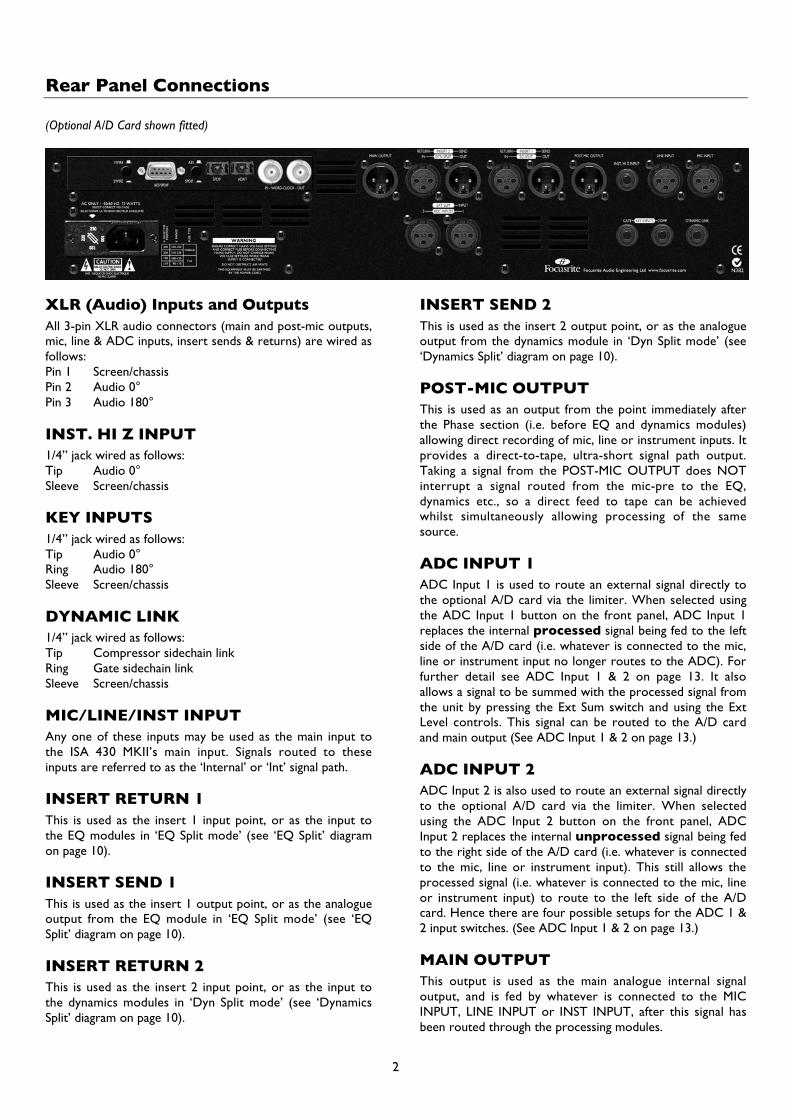
Rear Panel Connections
(Optional A/D Card shown fitted)
XLR (Audio) Inputs and OutputsAll 3-pin XLR audio connectors (main and post-mic outputs,mic, line & ADC inputs, insert sends & returns) are wired asfollows:Pin 1 Screen/chassisPin 2 Audio 0°Pin 3 Audio 180°
INST. HI Z INPUT1/4” jack wired as follows:Tip Audio 0°Sleeve Screen/chassis
KEY INPUTS1/4” jack wired as follows:Tip Audio 0°Ring Audio 180°Sleeve Screen/chassis
DYNAMIC LINK1/4” jack wired as follows:Tip Compressor sidechain linkRing Gate sidechain linkSleeve Screen/chassis
MIC/LINE/INST INPUTAny one of these inputs may be used as the main input tothe ISA 430 MKII’s main input. Signals routed to theseinputs are referred to as the ‘Internal’ or ‘Int’ signal path.
INSERT RETURN 1This is used as the insert 1 input point, or as the input tothe EQ modules in ‘EQ Split mode’ (see ‘EQ Split’ diagramon page 10).
INSERT SEND 1This is used as the insert 1 output point, or as the analogueoutput from the EQ module in ‘EQ Split mode’ (see ‘EQSplit’ diagram on page 10).
INSERT RETURN 2This is used as the insert 2 input point, or as the input tothe dynamics modules in ‘Dyn Split mode’ (see ‘DynamicsSplit’ diagram on page 10).
INSERT SEND 2This is used as the insert 2 output point, or as the analogueoutput from the dynamics module in ‘Dyn Split mode’ (see‘Dynamics Split’ diagram on page 10).
POST-MIC OUTPUTThis is used as an output from the point immediately afterthe Phase section (i.e. before EQ and dynamics modules)allowing direct recording of mic, line or instrument inputs. Itprovides a direct-to-tape, ultra-short signal path output.Taking a signal from the POST-MIC OUTPUT does NOTinterrupt a signal routed from the mic-pre to the EQ,dynamics etc., so a direct feed to tape can be achievedwhilst simultaneously allowing processing of the samesource.
ADC INPUT 1ADC Input 1 is used to route an external signal directly tothe optional A/D card via the limiter. When selected usingthe ADC Input 1 button on the front panel, ADC Input 1replaces the internal processed signal being fed to the leftside of the A/D card (i.e. whatever is connected to the mic,line or instrument input no longer routes to the ADC). Forfurther detail see ADC Input 1 & 2 on page 13. It alsoallows a signal to be summed with the processed signal fromthe unit by pressing the Ext Sum switch and using the ExtLevel controls. This signal can be routed to the A/D cardand main output (See ADC Input 1 & 2 on page 13.)
ADC INPUT 2ADC Input 2 is also used to route an external signal directlyto the optional A/D card via the limiter. When selectedusing the ADC Input 2 button on the front panel, ADCInput 2 replaces the internal unprocessed signal being fedto the right side of the A/D card (i.e. whatever is connectedto the mic, line or instrument input). This still allows theprocessed signal (i.e. whatever is connected to the mic, lineor instrument input) to route to the left side of the A/Dcard. Hence there are four possible setups for the ADC 1 &2 input switches. (See ADC Input 1 & 2 on page 13.)
MAIN OUTPUTThis output is used as the main analogue internal signaloutput, and is fed by whatever is connected to the MICINPUT, LINE INPUT or INST INPUT, after this signal hasbeen routed through the processing modules.
2

3
DYNAMIC LINKYou can connect two ISA 430 MKII units (using a standardTRS 1/4” jack-to-jack lead between the DYNAMIC LINKsockets) to allow both the compressor and gate sections tobehave as stereo pairs of processors. When connected inthis way, the compressors and gates behave as single stereodevices. Both units respond to the higher of the two inputsignal path levels. (The EQ channels can be matched visuallyor aurally to be used as a stereo pair if required.) Hence, todrive the compressors and gates as stereo pairs, set thethreshold pot of one of the compressors and one of the
gates to maximum (fully clockwise). The second unit willthen act as ‘master’, allowing one set of parameter changesto affect both compressors or gates identically. NB: The de-essers are not linked.
Retrofitting the Optional A/D CardThe optional A/D card can be retrofitted to a standard ISA430 MKII at any time. Full fitting instructions for this optionare included with the Card.
ISA 430 MKII Front Panel Controls
PowerApplies power to the unit. Turn on the ISA 430 MKII beforepowering up devices to which the outputs are connected.
Inst InputUnbalanced instrument sources may either be connected viathe rear panel INST. HI Z INPUT, or via this duplicatedfront panel jack. If both are connected, the front connectionoverrides the rear connection. No DI box is required.
Metering
Meter SourceThe VU meter can display input level, Insert 1 return level,Insert 2 return level, compressor gain reduction orsidechain Listen level. Press the Meter Source button tostep through Input, Insert Rtn 1, Insert Rtn 2 and Compsources as indicated by the corresponding LEDs. Thesidechain Listen level will automatically be displayed on the
VU meter when the Listen switches are pressed in thecompresser, gate or de-esser sections. The Listen LED willalso light when any of these switches are selected.
Meter 0VU CalibrationThe metering calibration for the input level and insertreturn levels can be shown over two different ranges:
• 0VU corresponds to +4dBu.• 0VU corresponds to +18dBu.
Either can be selected via the Meter 0VU Calibrationbutton. For the compressor, the meter indicates theamount of gain reduction applied, from 0VU (nocompression) to -20VU (corresponding to 20dB of gainreduction). NB: The effect upon ‘Listen’ of calibration issimilar to that on input and insert returns. However, as thesignal being monitored by the listen circuit is a sidechainsource, the meter acts more as a visual indication of theattack and decay of a signal, rather than true level.
Listen LEDThis illuminates when Listen is selected on the compressor,expander/gate or de-esser, and indicates that the unit ismonitoring the selected sidechain frequencies. N.B. Whenattempting to listen to the dynamics in ‘Split Dynamics’mode, pressing the Listen switch will only result in visualmonitoring; as the dynamics are split from the monitoringpath, they can be viewed in the meter but not heard.
Audio O/L LEDThis LED illuminates when the peak signal level reaches orexceeds +20dBu, or when the peak signal level reaches 6dBbelow the clip point. The signal is monitored at five points:post-the input gain Trim, post-Insert 1, post-the EQ
3

module, post-Insert 2, and post-the Dynamics module (sinceeach module could cause clipping if incorrectly set up).Occasional short-duration peaks which may cause the LEDto blink will not normally cause audible distortion, but if theLED is lit constantly, the level in the appropriate moduleshould be reduced to prevent overloading.
Digital Output Meters
Two LED bargraph metersmonitor the level being fedto the output (left meter)and input (right meter) ofthe unit.
They also display thechannels of the optionalADC card when the ADCInput 1 and ADC Input 2switches are selected. Themeters provide a widerange from –42dBFS (-20dBu) to 0dBFS (+22dBu).
The output meter monitoring point is just before the ADCinput; this means that if the limiter is switched in the actionof the limiter can be seen on the meter. This monitor pointis also post-the output level control. When ADC Input 1 isselected the meter is fed from ADC Input 1. The inputmeter monitoring point is post-the phase switch. WhenADC Input 2 is selected the meter is fed from the ADCInput 2.
Input Stage
Three input options areprov ided to g i vecompatibility with mic,l ine or instrumentsources. An immediately-post-input-stage, balancedou tpu t ( POST-MICOUTPUT) is provided on
the rear panel giving an ultra-short signal path to allow forthe cleanest possible recordings. N.B. The POST-MICOUTPUT can be used in conjunction with the main output,allowing the user to record a dry signal for archive/safetypurposes, at the same time as recording the processedoutput.
SelectPressing Select steps through each of the three inputs asindicated by the corresponding LEDs. When the Mic LED islit, the mic input is active etc. Only one of the Mic, Line orInstrument inputs can be used.
Mic Input GainWith the mic input selected, the user has access to the fullgain range in 10dB steps from 0dB to +60dB (yellow
legend). The gain range is split between two gain modesdepending upon the status of the 30-60 switch:
Mode 1: Mic Gain Range 0-30With the 30-60 switch off, the rotary gain knob operatesover a gain range of 0dB to +30dB, the level of gain chosenbeing indicated on the front panel by the outer arc of yellownumbers around the gain knob.
Mode 2: Mic Gain Range 30-60With the 30-60 switch on (illuminated), the rotary gainknob operates over a gain range of 30dB to 60dB, the levelof gain chosen being indicated on the front panel by theouter arc of yellow numbers around the gain knob.
An additional 20dB of gain can be applied to the signal afterthe Mic/Line gain knob using the Trim knob. See Trimcontrol text below for full explanation.
Line Input GainWith the line input selected, the user has access to gainsettings ranging from –20dB to +10dB, indicated on thefront panel by the arc of white numbers around the gainknob. The 30-60 switch is inactive when the line input isselected, as the gain range for Line level inputs is restrictedto –20dB to +10dB in 10dB steps.
An additional 20dB of gain can be applied to the signal afterthe Mic/line gain knob using the Trim knob. See Trimcontrol text below for full explanation.
Instrument Input GainWith the instrument input selected, gain is applied to theinput signal by using the Trim control only, which allows+10dB to +40dB of gain range. The level of gain chosen isindicated on the front panel by the outer arc of yellownumbers around the gain knob. This input is suitable forhigh impedance sources such as guitar or bass pickups(which may be connected directly without the need for anexternal DI box), or vintage synthesizers with highimpedance outputs.
TrimThe Trim control provides additional variable gain of 0dB to+20dB when mic or line inputs are selected. The level ofgain chosen is indicated on the front panel by the inner arcof white numbers around the gain knob. The additional20dB of gain that can be applied to the Mic or Line signal isvery useful for two reasons:
When high gain is requiredThe trim used in conjunction with the Mic gain of 60dB willgive a total of up to 80dB of pre-amp gain, making it veryuseful for getting good digital recording levels from very lowoutput devices, such as dynamic and ribbon microphones.
Gain adjustment during recordingWhen small amounts of gain adjustment are needed tocorrect for performance level variations during recording,use the trim knob rather than the stepped Mic/Line gainknob, as switching the 10dB gain steps will be much too
4

intrusive. It is therefore good practice to apply some Trimgain before using the 10dB stepped gain knob to find theoptimum recording level so that the Trim control can beused to gently add or take away gain later, if so required.
+48VPressing the +48V switch provides +48V phantom power,suitable for condenser microphones, to the rear panel XLRmicrophone connector. This switch does not affect theother inputs. If you are unsure whether your microphonerequires phantom power, refer to its handbook, as it ispossible to damage some microphones (most notablyribbon microphones) by providing phantom power.
PhasePressing Phase inverts the phase of the selected input. Thisis primarily used to correct phase problems when usingmultiple microphones on a single source.
ImpedancePressing Impedance steps through each of the fourtransformer pre-amp input impedance values, as indicatedby their corresponding LEDs. By selecting different valuesfor the impedance of the ISA 430 MKII transformer input,the performance of both the ISA 430 MKII pre-amp and themicrophone connected can be tailored to set the desiredlevel and frequency response.
Mic AirPressing Mic Air increases the impedance effect of thetransformer on high frequencies. Transformers impart aneffect which is often referred to as ‘air’, adding aspaciousness to the sound of the mic pre-amp. Mic Airfurther emphasises this effect. For further deails see FAQnumber 18 on page 22.
EQ Module
All EQPressing All EQ activates all sections of the EQ module(including the Hi and Lo Pass Filters), placing the wholemodule in the audio path. Toggling All EQ allows an A/Bcomparison of EQ’d/flat settings, without having to switcheach section of the EQ individually, and without usingBypass which switches both EQ and dynamics modules in orout of the audio path. The Comp and Gate switches onindividual EQ sections (see below) operate independentlyfrom the All EQ switch.
Filter InPress Filter In to make the Hi and Lo Pass Filters active inthe audio path. This selection is cancelled if Comp or Gateis pressed. Both filters provide 18dB/octave roll-off, andsince the filter frequencies overlap they may be configuredas a very tight bandpass filter for creative compression andgating; use when you wish to select a specific instrument ornarrow frequency band from a complex signal, then feed tothe sidechain of the compressor or gate.
Low Pass FilterSets a roll-off frequency from 400Hz to 22kHz.
High Pass FilterSets a roll-off frequency from 20Hz to 1k6Hz.
CompWhen the Comp switch is pressed, both Hi and Lo passfilters are inserted in the compressor sidechain to enablefrequency-selective (aka frequency-conscious) compression.This selection is cancelled if Filter In or Gate is pressed.
GateWhen the Gate switch is pressed both filters are inserted inthe gate sidechain to enable accurate drum gating. Thisselection is cancelled if Filter In or Comp is pressed.
Parametric EQTwo separate bands of parametric EQ, hi-mid and low-mid,are provided, each with continuously variable boost/cutwith centre detent, sweep control with two ranges, andfully variable Q. The first band covers the range 40Hz to400Hz (120Hz to 1k2Hz when x3 is pressed) and thesecond band covers 600Hz to 6kHz (1k8Hz to 18kHz whenx3 is pressed).
5

Param EQ InPress in to switch the parametric EQ into the signal path.This selection is cancelled if Gate or Comp is pressed.
x3The Sweep controls have two ranges, the higher beingselected when the x3 switch is pressed ( x3 frequencies areshown in yellow on the panel).
CompWhen the Comp switch is pressed, the parametric EQ isinserted into the compressor sidechain, allowing frequency-selective (frequency-conscious) compression. This selectionis cancelled if Param EQ In or Gate is pressed.
GateWhen the Gate switch is pressed, the parametric EQ isinserted into the gate sidechain for e.g. accurate drumgating. This selection is cancelled if Param EQ In or Comp ispressed.
Shelving EQHigh and low frequency-shelving sections are available, eachwith continuously variable boost/cut with center detent, anda four position rotary switch for selection of roll-offfrequency. In addition, the Hi Range switch allows for tworanges of roll-off frequency per band – resulting in eightfrequency selections in total.
Shelving EQ InPress in to switch the shelving EQ into the signal path. Thisselection is cancelled if Gate or Comp is pressed.
Hi RangeThe frequency controls have two ranges, the higher beingselected when the Hi Range switch is pressed (frequenciesshown in yellow on the panel).
LOW SHELF
HI RANGE HI RANGE
0Hz
20
33
460
655
1k5
2k2
15k
18k
HIGH SHELF
Low frequency shelvingThe frequency range steps are 20Hz, 56Hz, 160Hz and460Hz (33Hz, 95Hz, 270Hz and 655Hz when Hi Rangeswitch is engaged).
High frequency shelvingThe frequency range steps are 1.5kHz, 3.3kHz, 6.8kHz and15kHz (2.2kHz, 4.7kHz, 10kHz and 18khz when Hi Range isengaged).
CompWhen the Comp switch is pressed, the shelving EQ isinserted into the compressor sidechain, allowing frequency-selective (frequency-conscious) compression. This selectionis cancelled if Shelving EQ In or Gate is pressed.
GateWhen the Gate switch is pressed, the shelving EQ isinserted into the gate sidechain for e.g. accurate drumgating. This selection is cancelled if Shelving EQ In or Compis pressed.
Compressor
Comp InPress Comp In to switch the compressor into the signalpath. Note that the VU meter can be selected to display thecompressor gain reduction (see Metering section, page 3).
6
ListenPress to allow audio monitoring of the compressorsidechain to assist accurate frequency adjustment whensetting up frequency-conscious compression. The ListenLED below the main VU meter illuminates to show thatListen mode is active. Note that the VU meter automaticallydisplays the compressor sidechain listen level when a Listenswitch is pressed in (see Metering section, page 3).
VintageThe Vintage switch activates the vintage compressor. Thishas two modes, Comp and Lim, as indicated by the LEDs tothe right of the Vintage switch. The Vintage switch stepsthrough the different modes of compressor operation.
In Comp mode the compressor is a vintage optocompressor. In Lim mode the compressor acts more like avintage opto limiter with a harder ratio and knee. Whenneither the Comp or Lim LEDs are illuminated thecompressor is in the classic Focusrite discrete Class A VCAmode.
N.B. When in Vintage Comp or Lim mode the Attack,Release, Auto Release and Ext Key controls are inactive.
MakeupCompression results in an overall reduction in level. TheMakeup control allows you to restore the compressor’soutput level back to the original level.
RatioThe Ratio control determines the rate at whichcompression is applied to the signal with increasing input,and is the ratio of change in input level compared to changein output level. The control gives a range of 1.5 to 10.Higher ratio settings will produce more noticeablecompression, so for the least obtrusive result, the ratioshould be set at the minimum necessary for the application.
For example, using low threshold and low ratio will producea less noticeable effect than a high threshold and high ratio,even though the total amount of compression may be thesame.
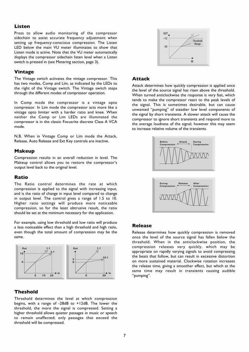
ThesholdThreshold determines the level at which compressionbegins, with a range of -28dB to +12dB. The lower thethreshold, the more the signal is compressed. Setting ahigher threshold allows quieter passages in music or speechto remain unaffected; only passages that exceed thethreshold will be compressed.
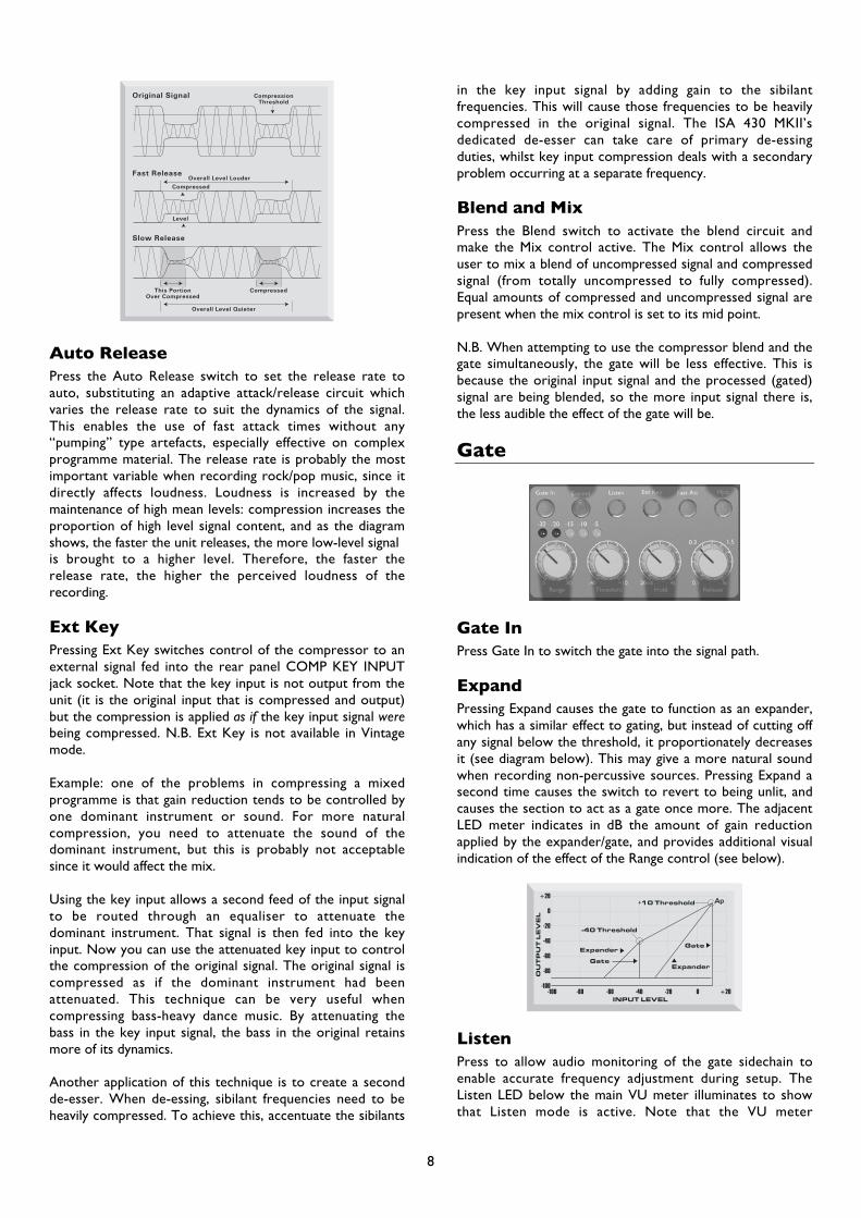
AttackAttack determines how quickly compression is applied oncethe level of the source signal has risen above the threshold.When turned anticlockwise the response is very fast, whichtends to make the compressor react to the peak levels ofthe signal. This is sometimes desirable, but can causeunwanted “pumping” of steadier low level components ofthe signal by short transients. A slower attack will cause thecompressor to ignore short transients and respond more tothe average loudness of the signal; however this may seemto increase relative volume of the transients.
ReleaseRelease determines how quickly compression is removedonce the level of the source signal has fallen below thethreshold. When in the anticlockwise position, thecompression releases very quickly, which may beappropriate on rapidly varying signals to avoid compressingthe beats that follow, but can result in excessive distortionon more sustained material. Clockwise rotation increasesthe release time, giving a smoother effect, but which at thesame time may result in transients causing audible“pumping”.
7
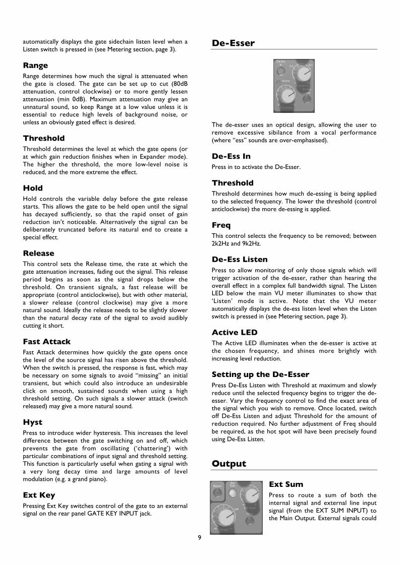
Auto ReleasePress the Auto Release switch to set the release rate toauto, substituting an adaptive attack/release circuit whichvaries the release rate to suit the dynamics of the signal.This enables the use of fast attack times without any“pumping” type artefacts, especially effective on complexprogramme material. The release rate is probably the mostimportant variable when recording rock/pop music, since itdirectly affects loudness. Loudness is increased by themaintenance of high mean levels: compression increases theproportion of high level signal content, and as the diagramshows, the faster the unit releases, the more low-level signalis brought to a higher level. Therefore, the faster therelease rate, the higher the perceived loudness of therecording.
Ext KeyPressing Ext Key switches control of the compressor to anexternal signal fed into the rear panel COMP KEY INPUTjack socket. Note that the key input is not output from theunit (it is the original input that is compressed and output)but the compression is applied as if the key input signal werebeing compressed. N.B. Ext Key is not available in Vintagemode.
Example: one of the problems in compressing a mixedprogramme is that gain reduction tends to be controlled byone dominant instrument or sound. For more naturalcompression, you need to attenuate the sound of thedominant instrument, but this is probably not acceptablesince it would affect the mix.
Using the key input allows a second feed of the input signalto be routed through an equaliser to attenuate thedominant instrument. That signal is then fed into the keyinput. Now you can use the attenuated key input to controlthe compression of the original signal. The original signal iscompressed as if the dominant instrument had beenattenuated. This technique can be very useful whencompressing bass-heavy dance music. By attenuating thebass in the key input signal, the bass in the original retainsmore of its dynamics.
Another application of this technique is to create a secondde-esser. When de-essing, sibilant frequencies need to beheavily compressed. To achieve this, accentuate the sibilants
in the key input signal by adding gain to the sibilantfrequencies. This will cause those frequencies to be heavilycompressed in the original signal. The ISA 430 MKII’sdedicated de-esser can take care of primary de-essingduties, whilst key input compression deals with a secondaryproblem occurring at a separate frequency.
Blend and MixPress the Blend switch to activate the blend circuit andmake the Mix control active. The Mix control allows theuser to mix a blend of uncompressed signal and compressedsignal (from totally uncompressed to fully compressed).Equal amounts of compressed and uncompressed signal arepresent when the mix control is set to its mid point.
N.B. When attempting to use the compressor blend and thegate simultaneously, the gate will be less effective. This isbecause the original input signal and the processed (gated)signal are being blended, so the more input signal there is,the less audible the effect of the gate will be.
Gate
Gate InPress Gate In to switch the gate into the signal path.
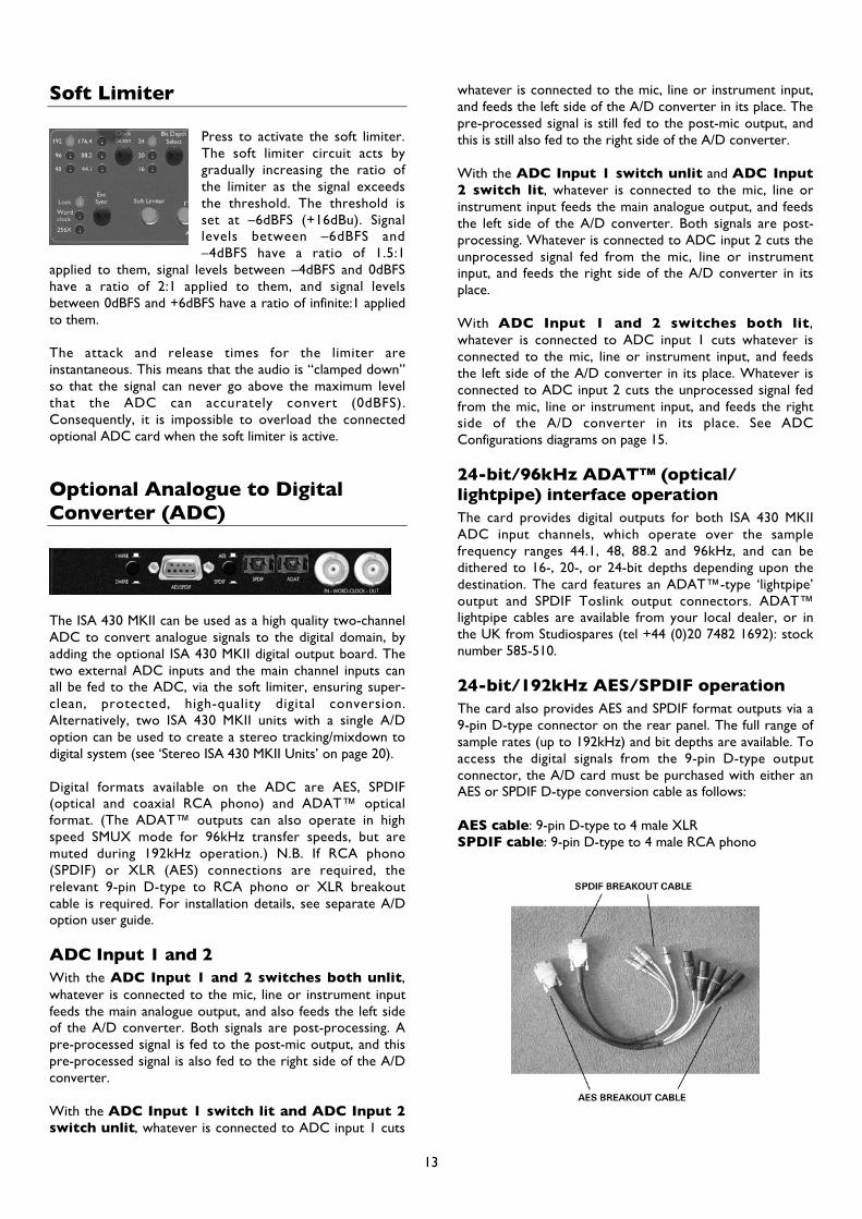
ExpandPressing Expand causes the gate to function as an expander,which has a similar effect to gating, but instead of cutting offany signal below the threshold, it proportionately decreasesit (see diagram below). This may give a more natural soundwhen recording non-percussive sources. Pressing Expand asecond time causes the switch to revert to being unlit, andcauses the section to act as a gate once more. The adjacentLED meter indicates in dB the amount of gain reductionapplied by the expander/gate, and provides additional visualindication of the effect of the Range control (see below).
ListenPress to allow audio monitoring of the gate sidechain toenable accurate frequency adjustment during setup. TheListen LED below the main VU meter illuminates to showthat Listen mode is active. Note that the VU meter
8
automatically displays the gate sidechain listen level when aListen switch is pressed in (see Metering section, page 3).
RangeRange determines how much the signal is attenuated whenthe gate is closed. The gate can be set up to cut (80dBattenuation, control clockwise) or to more gently lessenattenuation (min 0dB). Maximum attenuation may give anunnatural sound, so keep Range at a low value unless it isessential to reduce high levels of background noise, orunless an obviously gated effect is desired.
ThresholdThreshold determines the level at which the gate opens (orat which gain reduction finishes when in Expander mode).The higher the threshold, the more low-level noise isreduced, and the more extreme the effect.
HoldHold controls the variable delay before the gate releasestarts. This allows the gate to be held open until the signalhas decayed sufficiently, so that the rapid onset of gainreduction isn’t noticeable. Alternatively the signal can bedeliberately truncated before its natural end to create aspecial effect.
ReleaseThis control sets the Release time, the rate at which thegate attenuation increases, fading out the signal. This releaseperiod begins as soon as the signal drops below thethreshold. On transient signals, a fast release will beappropriate (control anticlockwise), but with other material,a slower release (control clockwise) may give a morenatural sound. Ideally the release needs to be slightly slowerthan the natural decay rate of the signal to avoid audiblycutting it short.
Fast AttackFast Attack determines how quickly the gate opens oncethe level of the source signal has risen above the threshold.When the switch is pressed, the response is fast, which maybe necessary on some signals to avoid “missing” an initialtransient, but which could also introduce an undesirableclick on smooth, sustained sounds when using a highthreshold setting. On such signals a slower attack (switchreleased) may give a more natural sound.
HystPress to introduce wider hysteresis. This increases the leveldifference between the gate switching on and off, whichprevents the gate from oscillating (‘chattering’) withparticular combinations of input signal and threshold setting.This function is particularly useful when gating a signal witha very long decay time and large amounts of levelmodulation (e.g. a grand piano).
Ext KeyPressing Ext Key switches control of the gate to an externalsignal on the rear panel GATE KEY INPUT jack.
De-Esser
The de-esser uses an optical design, allowing the user toremove excessive sibilance from a vocal performance(where “ess” sounds are over-emphasised).
De-Ess InPress in to activate the De-Esser.
ThresholdThreshold determines how much de-essing is being appliedto the selected frequency. The lower the threshold (controlanticlockwise) the more de-essing is applied.
FreqThis control selects the frequency to be removed; between2k2Hz and 9k2Hz.
De-Ess ListenPress to allow monitoring of only those signals which willtrigger activation of the de-esser, rather than hearing theoverall effect in a complex full bandwidth signal. The ListenLED below the main VU meter illuminates to show that‘Listen’ mode is active. Note that the VU meterautomatically displays the de-ess listen level when the Listenswitch is pressed in (see Metering section, page 3).
Active LEDThe Active LED illuminates when the de-esser is active atthe chosen frequency, and shines more brightly withincreasing level reduction.
Setting up the De-EsserPress De-Ess Listen with Threshold at maximum and slowlyreduce until the selected frequency begins to trigger the de-esser. Vary the frequency control to find the exact area ofthe signal which you wish to remove. Once located, switchoff De-Ess Listen and adjust Threshold for the amount ofreduction required. No further adjustment of Freq shouldbe required, as the hot spot will have been precisely foundusing De-Ess Listen.
Output
Ext SumPress to route a sum of both theinternal signal and external line inputsignal (from the EXT SUM INPUT) tothe Main Output. External signals could
9

be a double track, an extra mic from a second ISA 430MKII, or live reverb.
Ext LevelThis control adjusts the gain of the external line input whichmay be summed into the Main Output (see above).
OutputAdjusts the Main Output level between -60dB and +6dB.
MutePress to mute the output of both the Main Output andPost-Mic Output. N.B. Analogue sends and digital outputsare not muted.
BypassAll EQ and dynamics processing modules can be globallyswitched out using the Bypass switch, for quick A/Bcomparison of processed/unprocessed signals.
Inserts and Routing Matrix
The ISA 430 MKII has two insert points and a very comprehensive set of routing options.
Insert 1Activated by the Insert 1 In switch. The insert 1send and return are both balanced XLRs and aresituated post- the Phase switch. Insert 1 Send andReturn always remain pre- any of the processingsections (EQ, dynamics etc).
Using Insert 1 as ‘traditional’ insert:
MICLINEINST
INSERT1
SEND
INSERT1
RETURN
LEVELTRIM &PHASE
EQ DYNAMICS
EQ SplitActivated by the EQ Split switch. This allows the INSERTSEND 1 and INSERT RETURN 1 connections to act asinputs and outputs to the EQ section only, thus giving aseparate line level EQ unit, which acts independently fromthe dynamics processing. When EQ Split is selected, theInsert 1 switch, if lit, wll go out. This is because Insert 1 isnow being used as the input and output to the EQ section,and so is no longer available for use as a ‘traditional’ insert.
Using Insert 1 to split EQ:
MICLINEINST
INSERT1
RETURN
INSERT1
SEND
LEVELTRIM &PHASE
EQ
DYNAMICS
Dynamics SplitActivated by the Dyn Split switch. This allows the INSERT SEND 2 and INSERT RETURN 2 connections to act as independentinputs and outputs to the dynamics section only, thus giving a separate line level dynamics unit. When Dyn Split is selected, theInsert 2 and Post-Dyn switches, if lit, will go out. This is because Insert 2 is now being used as the input and output to thedynamics section, and so is no longer available for use as a ‘traditional’ insert.
Using Insert 2 to split dynamics:
MICLINEINST
INSERT1
SEND
INSERT1
RETURN
LEVELTRIM &PHASE
EQ
DYNAMICS
INSERT2
RETURN
INSERT2
SEND
O/PLEVEL
LIMITERANALOGUE
OUTPUTADC
METERS
EXTSUM
10

Dynamics position switch
Allows the dynamics section to be placed in three different positions in the processing chain. (Normally the dynamicssection is the second processing section in the signal path, after the EQ section.) When activated, the new position of thedynamics section is indicated by the LEDs below the Dynamics switch.
a) Dynamics Post-EQ (Default)
MICLINEINST
INSERT1
SEND
INSERT1
RETURN
LEVELTRIM &PHASE
EQ DYNAMICS
INSERT2
SEND
INSERT2
RETURN
O/PLEVEL
LIMITERANALOGUE
OUTPUTADC
METERS
EXTSUM
b) Dynamics Pre-EQPressing Dynamics once reverses the position of the EQ and dynamics sections, placing dynamics first and EQ afterwards. ThePre-EQ LED illuminates to provide visual confirmation of the dynamics’ pre-EQ position.
MICLINEINST
INSERT1
SEND
INSERT1
RETURN
LEVELTRIM &PHASE
EQDYNAMICS
INSERT2
SEND
INSERT2
RETURN
O/PLEVEL
LIMITERANALOGUE
OUTPUTADC
METERS
EXTSUM
c) Dynamics Post-SumPressing Dynamics a second time places the dynamics section after the Ext Sum, Ext Level and Output faders but before thelimiter. The Post-Sum LED illuminates to provide visual confirmation of the dynamics’ POST-SUM position. This allows theexternal signal, which has been summed to the main input signal, to be processed through the dynamics section of the ISA 430MKII. Pressing Dynamics a third time returns the dynamics section to its default position (post-EQ, pre-Sum) where both thePre-EQ and Post-Sum LEDs are unlit.
MICLINEINST
INSERT1
SEND
INSERT1
RETURN
LEVELTRIM &PHASE
EQ DYNAMICS
INSERT2
SEND
INSERT2
RETURN
O/PLEVEL
LIMITERANALOGUE
OUTPUTADC
METERS
EXTSUM
11

Insert 2
Activated by the Insert 2 In switch. The insert 2 send and return are both balanced XLRs and can be placed in fourdifferent positions in the signal path dependant upon the relative positions of the Post-Dyn and Dyn Split switches. (N.B.It is not possible to have the following combination of switches for Insert 2: Insert 2 In + Post-Dyn + Dynamics Post-Sum.)
a) Insert 2 InInsert 2 placed post-EQ and pre-dynamics.
MICLINEINST
INSERT1
SEND
INSERT1
RETURN
LEVELTRIM &PHASE
EQ DYNAMICS
INSERT2
SEND
INSERT2
RETURN
O/PLEVEL
LIMITERANALOGUE
OUTPUTADC
METERS
EXTSUM
b) Insert 2 In + Post-DynInsert 2 placed post-dynamics and post-EQ
MICLINEINST
INSERT1
SEND
INSERT1
RETURN
LEVELTRIM &PHASE
DYNAMICSEQ
INSERT2
SEND
INSERT2
RETURN
O/PLEVEL
LIMITERANALOGUE
OUTPUTADC
METERS
EXTSUM
c) Insert 2 In + Dynamics Post-SumInsert 2 placed post-EQ and pre-sum/pre-dynamics (dynamics have moved post-sum).
MICLINEINST
INSERT1
SEND
INSERT1
RETURN
LEVELTRIM &PHASE
EQ DYNAMICS
INSERT2
SEND
INSERT2
RETURN
O/PLEVEL
LIMITERANALOGUE
OUTPUTADC
METERS
EXTSUM
d) Insert 2 In, Post-Dyn + Dynamics Pre-EQInsert 2 placed post-dynamics and pre-EQ.
MICLINEINST
INSERT1
SEND
INSERT1
RETURN
LEVELTRIM &PHASE
DYNAMICS EQ
INSERT2
SEND
INSERT2
RETURN
O/PLEVEL
LIMITERANALOGUE
OUTPUTADC
METERS
EXTSUM
(Examples a-d show Insert 2 being used as a ‘traditional’ insert.)
12
Soft Limiter
Press to activate the soft limiter.The soft limiter circuit acts bygradually increasing the ratio ofthe limiter as the signal exceedsthe threshold. The threshold isset at –6dBFS (+16dBu). Signallevels between –6dBFS and–4dBFS have a ratio of 1.5:1
applied to them, signal levels between –4dBFS and 0dBFShave a ratio of 2:1 applied to them, and signal levelsbetween 0dBFS and +6dBFS have a ratio of infinite:1 appliedto them.
The attack and release times for the limiter areinstantaneous. This means that the audio is “clamped down”so that the signal can never go above the maximum levelthat the ADC can accurately convert (0dBFS).Consequently, it is impossible to overload the connectedoptional ADC card when the soft limiter is active.
Optional Analogue to DigitalConverter (ADC)
The ISA 430 MKII can be used as a high quality two-channelADC to convert analogue signals to the digital domain, byadding the optional ISA 430 MKII digital output board. Thetwo external ADC inputs and the main channel inputs canall be fed to the ADC, via the soft limiter, ensuring super-clean, protected, high-quality digital conversion.Alternatively, two ISA 430 MKII units with a single A/Doption can be used to create a stereo tracking/mixdown todigital system (see ‘Stereo ISA 430 MKII Units’ on page 20).
Digital formats available on the ADC are AES, SPDIF(optical and coaxial RCA phono) and ADAT™ opticalformat. (The ADAT™ outputs can also operate in highspeed SMUX mode for 96kHz transfer speeds, but aremuted during 192kHz operation.) N.B. If RCA phono(SPDIF) or XLR (AES) connections are required, therelevant 9-pin D-type to RCA phono or XLR breakoutcable is required. For installation details, see separate A/Doption user guide.
ADC Input 1 and 2With the ADC Input 1 and 2 switches both unlit,whatever is connected to the mic, line or instrument inputfeeds the main analogue output, and also feeds the left sideof the A/D converter. Both signals are post-processing. Apre-processed signal is fed to the post-mic output, and thispre-processed signal is also fed to the right side of the A/Dconverter.
With the ADC Input 1 switch lit and ADC Input 2switch unlit, whatever is connected to ADC input 1 cuts
whatever is connected to the mic, line or instrument input,and feeds the left side of the A/D converter in its place. Thepre-processed signal is still fed to the post-mic output, andthis is still also fed to the right side of the A/D converter.
With the ADC Input 1 switch unlit and ADC Input2 switch lit, whatever is connected to the mic, line orinstrument input feeds the main analogue output, and feedsthe left side of the A/D converter. Both signals are post-processing. Whatever is connected to ADC input 2 cuts theunprocessed signal fed from the mic, line or instrumentinput, and feeds the right side of the A/D converter in itsplace.
With ADC Input 1 and 2 switches both lit,whatever is connected to ADC input 1 cuts whatever isconnected to the mic, line or instrument input, and feedsthe left side of the A/D converter in its place. Whatever isconnected to ADC input 2 cuts the unprocessed signal fedfrom the mic, line or instrument input, and feeds the rightside of the A/D converter in its place. See ADCConfigurations diagrams on page 15.
24-bit/96kHz ADAT™ (optical/lightpipe) interface operationThe card provides digital outputs for both ISA 430 MKIIADC input channels, which operate over the samplefrequency ranges 44.1, 48, 88.2 and 96kHz, and can bedithered to 16-, 20-, or 24-bit depths depending upon thedestination. The card features an ADAT™-type ‘lightpipe’output and SPDIF Toslink output connectors. ADAT™lightpipe cables are available from your local dealer, or inthe UK from Studiospares (tel +44 (0)20 7482 1692): stocknumber 585-510.
24-bit/192kHz AES/SPDIF operationThe card also provides AES and SPDIF format outputs via a9-pin D-type connector on the rear panel. The full range ofsample rates (up to 192kHz) and bit depths are available. Toaccess the digital signals from the 9-pin D-type outputconnector, the A/D card must be purchased with either anAES or SPDIF D-type conversion cable as follows:
AES cable: 9-pin D-type to 4 male XLRSPDIF cable: 9-pin D-type to 4 male RCA phono
13
Note: cables need to be purchased separately. Since thereare two different cable options – XLR for AES and RCAphono for SPDIF – these are not included with the A/Dconverter options. Focusrite cables may be purchased fromyour local dealer. If you experience difficulty in obtainingthese cables, contact your local distributor as listed in theback of this manual.
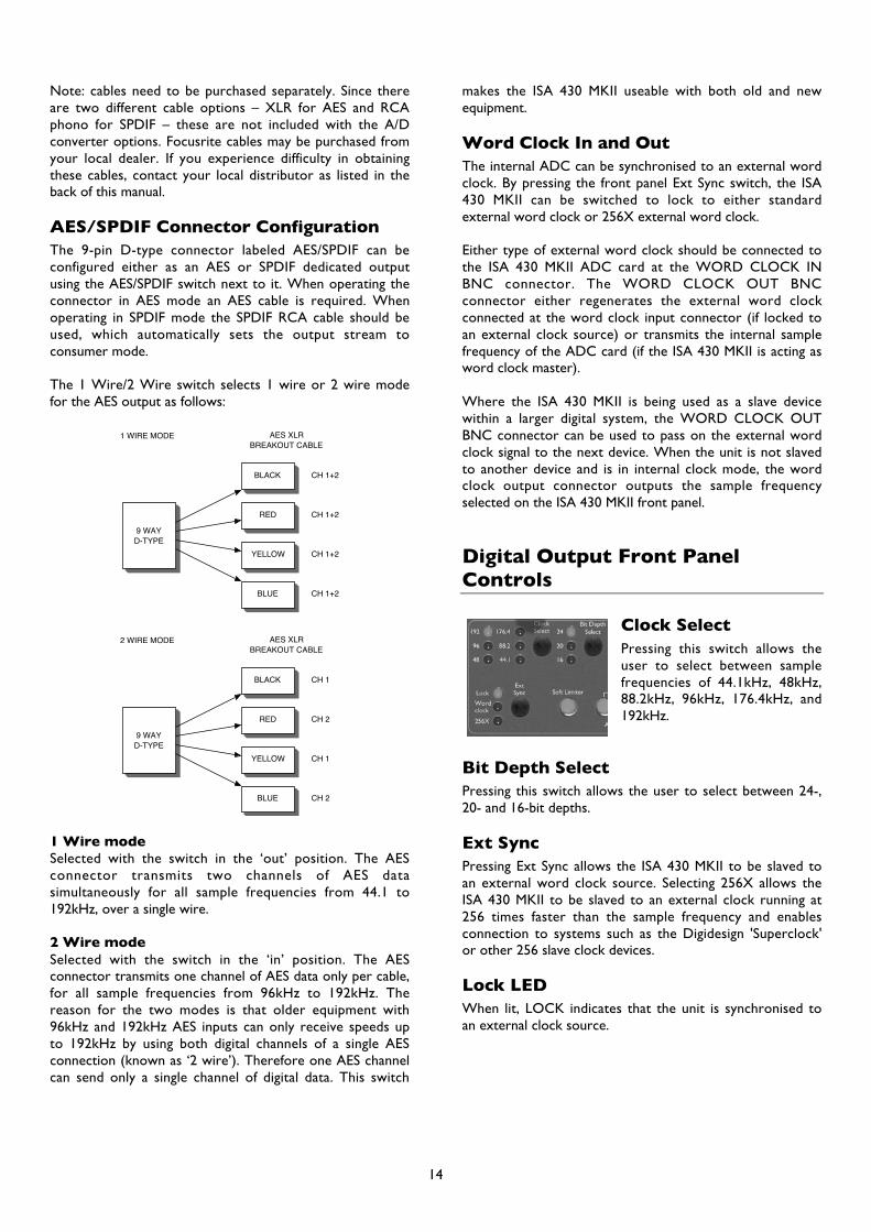
AES/SPDIF Connector ConfigurationThe 9-pin D-type connector labeled AES/SPDIF can beconfigured either as an AES or SPDIF dedicated outputusing the AES/SPDIF switch next to it. When operating theconnector in AES mode an AES cable is required. Whenoperating in SPDIF mode the SPDIF RCA cable should beused, which automatically sets the output stream toconsumer mode.
The 1 Wire/2 Wire switch selects 1 wire or 2 wire modefor the AES output as follows:
9 WAYD-TYPE
BLACK
RED
YELLOW
BLUE
1 WIRE MODE AES XLRBREAKOUT CABLE
CH 1+2
CH 1+2
CH 1+2
CH 1+2
9 WAYD-TYPE
BLACK
RED
YELLOW
BLUE
2 WIRE MODE AES XLRBREAKOUT CABLE
CH 1
CH 2
CH 1
CH 2
1 Wire modeSelected with the switch in the ‘out’ position. The AESconnector transmits two channels of AES datasimultaneously for all sample frequencies from 44.1 to192kHz, over a single wire.
2 Wire modeSelected with the switch in the ‘in’ position. The AESconnector transmits one channel of AES data only per cable,for all sample frequencies from 96kHz to 192kHz. Thereason for the two modes is that older equipment with96kHz and 192kHz AES inputs can only receive speeds upto 192kHz by using both digital channels of a single AESconnection (known as ‘2 wire’). Therefore one AES channelcan send only a single channel of digital data. This switch
makes the ISA 430 MKII useable with both old and newequipment.
Word Clock In and OutThe internal ADC can be synchronised to an external wordclock. By pressing the front panel Ext Sync switch, the ISA430 MKII can be switched to lock to either standardexternal word clock or 256X external word clock.
Either type of external word clock should be connected tothe ISA 430 MKII ADC card at the WORD CLOCK INBNC connector. The WORD CLOCK OUT BNCconnector either regenerates the external word clockconnected at the word clock input connector (if locked toan external clock source) or transmits the internal samplefrequency of the ADC card (if the ISA 430 MKII is acting asword clock master).
Where the ISA 430 MKII is being used as a slave devicewithin a larger digital system, the WORD CLOCK OUTBNC connector can be used to pass on the external wordclock signal to the next device. When the unit is not slavedto another device and is in internal clock mode, the wordclock output connector outputs the sample frequencyselected on the ISA 430 MKII front panel.
Digital Output Front PanelControls
Clock SelectPressing this switch allows theuser to select between samplefrequencies of 44.1kHz, 48kHz,88.2kHz, 96kHz, 176.4kHz, and192kHz.
Bit Depth SelectPressing this switch allows the user to select between 24-,20- and 16-bit depths.
Ext SyncPressing Ext Sync allows the ISA 430 MKII to be slaved toan external word clock source. Selecting 256X allows theISA 430 MKII to be slaved to an external clock running at256 times faster than the sample frequency and enablesconnection to systems such as the Digidesign 'Superclock'or other 256 slave clock devices.
Lock LEDWhen lit, LOCK indicates that the unit is synchronised toan external clock source.
14
ADC Configurations
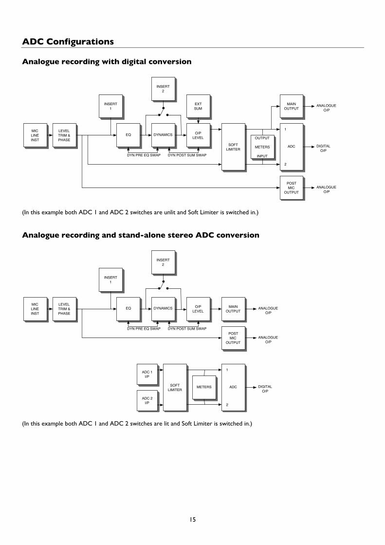
Analogue recording with digital conversion
MICLINEINST
POSTMIC
OUTPUT
INSERT1
LEVELTRIM &PHASE
DYNAMICSEQ
INSERT2
OUTPUT
METERS
INPUT
O/PLEVEL
SOFTLIMITER
MAINOUTPUT
EXTSUM
ADC
DYN PRE EQ SWAP DYN POST SUM SWAP
2
1
ANALOGUEO/P
DIGITALO/P
ANALOGUEO/P
(In this example both ADC 1 and ADC 2 switches are unlit and Soft Limiter is switched in.)
Analogue recording and stand-alone stereo ADC conversion
MICLINEINST
POSTMIC
OUTPUT
INSERT1
LEVELTRIM &PHASE
DYNAMICSEQ
INSERT2
METERS
O/PLEVEL
SOFTLIMITER
MAINOUTPUT
ADC 1I/P
ADC
DYN PRE EQ SWAP DYN POST SUM SWAP
2
1
ANALOGUEO/P
DIGITALO/P
ADC 2I/P
ANALOGUEO/P
(In this example both ADC 1 and ADC 2 switches are lit and Soft Limiter is switched in.)
15

Mic Pre-amp Input Impedance
A major element of the sound of a mic pre-amp is relatedto the interaction between the specific microphone beingused, and the type of mic pre-amp interface technology towhich it is connected. The main area in which thisinteraction has an effect is the level and frequency responseof the microphone, as follows:
• Level: Professional microphones tend to have lowoutput impedances, so more level can be achieved byselecting the higher impedance positions of the ISA 430MKII mic pre-amp.
• Frequency response: Microphones with definedpresence peaks and tailored frequency responses canbe further enhanced by choosing lower impedancesettings. Choosing higher input impedance values willtend to emphasise the high frequency response of themicrophone connected, allowing improved ambientinformation and high end clarity, even from average-performance microphones.
Various microphone/ISA 430 MKII pre-amp impedancecombinations can be tried to achieve the desired amount ofcolouration for the instrument or voice being recorded.
To understand how to use the impedance selectioncreatively it may be useful to read the following section onhow the microphone output impedance and the mic pre-amp input impedance interact.
Switchable Impedance: In DepthExplanation
Dynamic moving coil and condenser micsAlmost all professional dynamic and condensermicrophones are designed to have a relatively low nominaloutput impedance of between 150Ω and 300Ω whenmeasured at 1kHz. Microphones are designed to have suchlow output impedances because the following advantagesapply:
• They are less susceptible to noise pickup.• They can drive long cables without high frequency roll-
off due to cable capacitance.
The side-effect of having such low output impedance is thatthe mic pre-amp input impedance has a major effect on theoutput level of the microphone. Low pre-amp impedanceloads down the microphone output voltage, and emphasisesany frequency-related variation in microphone outputimpedance. Matching the mic pre-amp resistance to themicrophone output impedance, (e.g. making a pre-amp inputimpedance 200Ω to match a 200Ω microphone) stillreduces the microphone output and signal to noise ratio by6dB, which is undesirable.
To minimise microphone loading, and to maximise signal tonoise ratio, pre-amps have traditionally been designed tohave an input impedance about ten times greater than the
average microphone, around 1.2kΩ to 2kΩ. (The originalISA 110 pre-amp design followed this convention and has aninput impedance of 1.4kΩ at 1kHz.)
Input impedance settings greater than 2kΩ tend to makethe frequency-related variations of microphone output lesssignificant than at low impedance settings. Therefore highinput impedance settings yield a microphone performancethat is more flat in the low and mid frequency areas andboosted in the high frequency area when compared to lowimpedance settings.
Ribbon microphonesThe impedance of a ribbon microphone is worthy of specialmention, as this type of microphone is affected enormouslyby pre-amp impedance. The ribbon impedance within thistype of microphone is incredibly low, around 0.2Ω, andrequires an output transformer to convert the extremelylow voltage it can generate into a signal capable of beingamplified by a pre-amp. The ribbon microphone outputtransformer requires a ratio of around 1:30 (primary:secondary) to increase the ribbon voltage to a useful level,and this transformer ratio also has the effect of increasingthe output impedance of the mic to around 200Ω at 1kHz.
This transformer impedance, however, is very dependentupon frequency - it can almost double at some frequencies(known as the resonance point) and tends to roll off to verysmall values at low and high frequencies. Therefore, as withthe dynamic and condenser microphones, the mic pre-ampinput impedance has a massive effect on the signal levels andfrequency response of the ribbon microphone outputtransformer, and thus the ‘sound quality’ of themicrophone. It is recommended that a mic pre-ampconnected to ribbon microphone should have an inputimpedance of at least 5 times the nominal microphoneimpedance.
For a ribbon microphone impedance of 30Ω to 120Ω theISA 430 MKII’s input impedance of 600Ω (Low) will workwell, and for 120Ω to 200Ω ribbon microphones the inputimpedance setting of 1.4kΩ (ISA 110) is recommended.
Impedance Setting Quick Guide
High mic pre-amp impedance settings• Will generate more overall level• Will tend to make low- and mid-frequency response of
the microphone flatter• Will improve high-frequency response of the
microphone.
Low pre-amp impedance settings• Will reduce the microphone output level• Will tend to emphasise the low- and mid-frequency
presence peaks and resonant points of the microphone
16
Applications
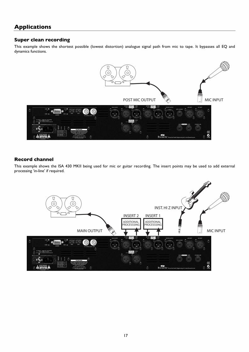
Super clean recordingThis example shows the shortest possible (lowest distortion) analogue signal path from mic to tape. It bypasses all EQ anddynamics functions.
MIC INPUTPOST MIC OUTPUT
Record channelThis example shows the ISA 430 MKII being used for mic or guitar recording. The insert points may be used to add externalprocessing ‘in-line’ if required.
MIC INPUTMAIN OUTPUT
INST. HI Z INPUT
INSERT 2ADDITIONAL
PROCESSSINGADDITIONAL
PROCESSSING
INSERT 1
17

Stereo ADCThe optional ADC card is a stereo device that can convert two tracks simultaneously. Routing to the ADC card can be donefrom the main internal signal (fed by the mic, line and inst. inputs). External signals can also be routed directly from the ADCInputs 1 & 2 on the rear panel, via the soft limiter. The digital meters automatically switch to monitor an ADC input when eitherone is selected. N.B. Input 1 of the ADC routes into the ISA 430 MKII at the same point as the main audio output. Input 2 of theADC routes to the same point as the post-mic output. (Requires optional ISA 430 MKII digital output board.)
ADC INPUT 1 & 2
ANALOGUESOURCE
DIGITAL IN
DIGITAL OUT
DAW
Split + digital record modeThis example shows an analogue input connected to Insert Return 1, and then routed, via the EQ modules, to Insert Send 1,which then feeds ADC Input 1. A second analogue input is connected to Insert Return 2, and then routed, via the dynamicsmodule, to Insert Send 2, which then feeds the ADC Input 2. This allows two separate sources to be processed and recorded viathe digital output. (Requires optional ISA 430 MKII digital output board.)
ADC INPUTS1 & 2
EQ SPLITDYNAMICS SPLIT
ANALOGUEINPUTS
DIGITAL IN
DIGITAL OUT
DAW
18
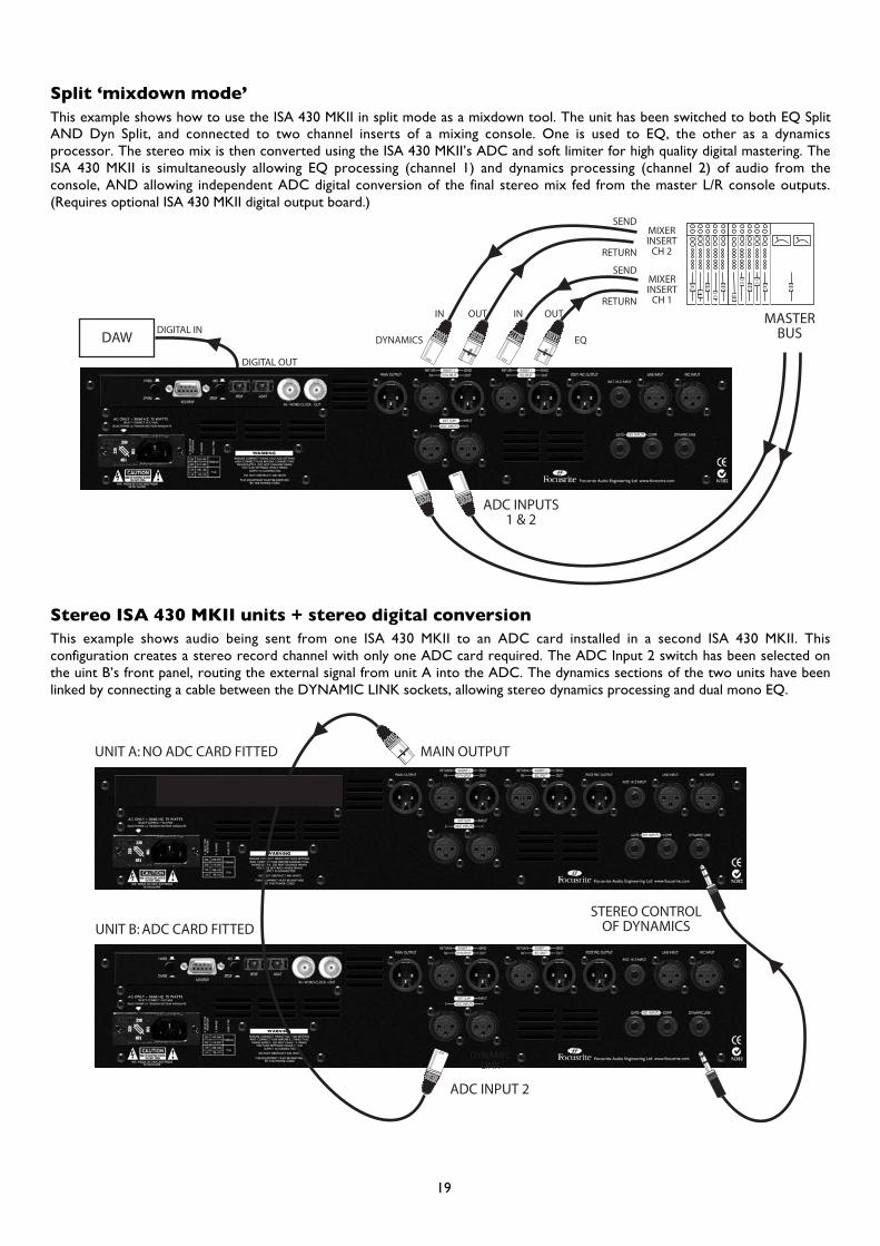
Split ‘mixdown mode’This example shows how to use the ISA 430 MKII in split mode as a mixdown tool. The unit has been switched to both EQ SplitAND Dyn Split, and connected to two channel inserts of a mixing console. One is used to EQ, the other as a dynamicsprocessor. The stereo mix is then converted using the ISA 430 MKII’s ADC and soft limiter for high quality digital mastering. TheISA 430 MKII is simultaneously allowing EQ processing (channel 1) and dynamics processing (channel 2) of audio from theconsole, AND allowing independent ADC digital conversion of the final stereo mix fed from the master L/R console outputs.(Requires optional ISA 430 MKII digital output board.)
ADC INPUTS1 & 2
MIXERINSERT
CH 1
MIXERINSERT
CH 2
MASTERBUSDYNAMICS EQ
ININ OUTOUT
SEND
SEND
RETURN
RETURN
DIGITAL IN
DIGITAL OUT
DAW
Stereo ISA 430 MKII units + stereo digital conversionThis example shows audio being sent from one ISA 430 MKII to an ADC card installed in a second ISA 430 MKII. Thisconfiguration creates a stereo record channel with only one ADC card required. The ADC Input 2 switch has been selected onthe uint B’s front panel, routing the external signal from unit A into the ADC. The dynamics sections of the two units have beenlinked by connecting a cable between the DYNAMIC LINK sockets, allowing stereo dynamics processing and dual mono EQ.
ADC INPUT 2
DYNAMICLINK
MAIN OUTPUTUNIT A: NO ADC CARD FITTED
UNIT B: ADC CARD FITTEDSTEREO CONTROL
OF DYNAMICS
19

Using the ISA 430 MKII as four discrete unitsThis example shows how to use the ISA 430 MKII as four individual processing units. This unit is switched to EQ Split AND DynSplit, and ADC Inputs 1 & 2 are switched on. The unit is simultaneously allowing EQ processing of audio, plus separate dynamicsprocessing of audio. At the same time it is allowing two channels of A/D conversion into a DAW as well as allowing super cleanmicrophone recording! (Requires optional ISA 430 MKII digital output board.)
MIXERINSERT
CH 1
MIXERINSERT
CH 2
DYNAMICS EQ
ININ OUTOUT
SEND
SEND
DIGITAL IN
DIGITAL OUT
RETURN
RETURN
MICINPUT
POST MICOUTPUT
ADC INPUT 1 & 2
ANALOGUESOURCE
DAW
Using Ext Sum to record a single source with two micsThis example shows an analogue output from Focusrite’s ISA 428 mic pre-amp routed into the EXT SUM Input on the ISA 430MKII. The EXT SUM switch is on and the signals’ levels are being balanced using the Ext Level control. The Dynamics switch hasbeen pressed to select Post-Sum. This shows how to record a single source such as a snare drum with two microphones,summing the signals together and then processing with the dynamics section.
MIC INPUTMAIN OUTPUT
EXT SUMINPUT
INPUT
OUTPUTISA 428
SOUNDSOURCE
20
FAQs
1. Are the EQ and Dynamics the originalFocusrite designs?Yes; the mic pre-amp, hi- and lo-pass filters, EQ,compressor, and expander/gate are all based on those usedin the original Focusrite console. However, the circuitry hasbeen expanded to incorporate new features; the ISA 110EQ having additional frequency options for its shelving andthe compressor now including opto-circuitry and extrarouting and controls. Plus, the mic pre-amp has a variableimpedance and new selectable ‘air’ effect.
2. Is the ISA 430 MKII a Class A device, and whyis that important?Yes, the 430 MKII is a Class A device. Why? Well, Class A isa type of amplifier design in which you have a standing DCcurrent running through your amplifier circuits all the time.As the signal comes along you vary what you're taking fromthat, rather than switching between supplying a positivecurrent for one half of the waveform and a negative currentfor the other half. This results in the ability to representaudio in a linear (distortion free) manner all the waythrough the circuit. Cheaper processors use IC amplifierswhich run close to Class B and don't have the same standingDC current, which means the transistors inside the chipsswitching off and on, inevitably resulting in less linearperformance.
3. What does the ‘Vintage’ compressor buttoninvolve?In addition to the Class A VCA circuit, the vintage opticalcircuit adds a whole new flavour of compression. Thevintage circuit operates in two modes, as a compressorcharacter or as a limiter. The attack and release are fixedwhen using the opto-circuit and the threshold point israised/the knee hardened when compressing with thelimiting characteristics selected.
4. So the compressor contains both VCAs andoptical technology?Yes. Whilst the expander and gate use solely VCAs and thede-esser and limiter are optical.
5. I’ve heard of the ‘pumping’ effect thatsometimes occurs when a signal is compressed.How can it be avoided?If the release time is too short, the signal level may ‘pump’ -in other words, you can hear the level of the signal going upand down. However, a release time that is too long willresult in the level of quiet sounds following a loud beat tobe reduced even further. In addition, having the thresholdset below the level of the kick drum and the release timeset relatively long will punch holes in the track as the leveldrops with each beat. If the release time is adjusted to bemuch faster then an entirely different, dynamic-soundingmix can be produced. As a rule, a good starting point forrelease time lies between 0.2 and 0.6 seconds.
6. What can the inserts do?Both inserts are “split-configurable”. This means that insert1 can split the EQ from the signal path if the option is
selected and insert 2 can split the dynamics. Also, insert 2 isflexible as to signal positioning and defaults to pre-dynamicsbut can move to post- if desired.
7. What if I want my dynamics processing tooccur pre-EQ or post-sum?No problem; the dynamics section can be switched so thatit precedes the EQ section by a single push of the Pre-EQbutton on the front panel. Pressing the Post Sum buttonplaces the dynamics section after the Ext Sum input. SeeInserts and Routing Matrix on page 10 for more details.
8. Is there any way to configure the ISA 430MKII as a stereo unit?Yes; although a single ISA 430 MKII can act only as a monoor split mono unit, it’s possible to link two MKIIs together,using the ‘dynamic link’ socket on the rear panel. Using asingle stereo TRS jack cable, this allows stereo operation ofthe compressor, plus dual mono EQ. You can also use asingle ISA 430 MKII as a stereo A/D converter. Seequestion 16 below for a full explanation.
9. How do I control which ISA 430 MKII will bethe controller and which will be the slave whenusing two together for stereo compression?Whichever ISA 430 MKII is generating the greater controlvoltage will be the controller. So, set one of the MKII’scompressors to minimum ratio and maximum threshold,and the other compressor will then always be the‘controller,’ with any changes made on the controller knobsaffecting both channels in the same way.
10. Can I wire the link cable to just link thecompressors or gates?Yes; the compressors are linked from tip to tip and thegates from ring to ring of the TRS jack lead. So, leaving thesleeves connected and disconnecting either of those lineswill enable the other to function as a stereo pair alone(whilst the disconnected one will act individually, as twoseparate comps/gates, on each mono signal).
11. I own an ISA 430. Can I link the dynamics toa MKII for use as a stereo pair?Yes; simply connect a link cable as described above. N.B.the ISA 430 MKII’s compressor must be set to VCA mode.
12. Does the ISA 430 MKII have the same kindof spectacular bandwidth that has given the Redrange its reputation for ‘open-ended’ sound?Yes. The bandwidth of the ISA 430 MKII is 10Hz to 200kHz!
13. Can I use all the different sections of the ISA430 MKII at once?Yes. If you want to use the mic pre, hi- and lo- pass filters,parametric and shelving EQ, compressor, expander/gate, de-esser, limiter and digital output all at the same time, as onehuge ‘super channel,’ you can. You can also take any sectionout of the signal path independently with a single buttonpush. Or you could use the ISA 430 MKII in ‘split mode.’
21

14. What is ‘split mode’?Split mode allows the ISA 430 MKII to act as separateprocessors at the same time, handling totally separate audiosignals. So one channel of audio can be routed through theEQ sections, with a second, discrete audio channel beingrouted through the dynamics sections. Furthermore, if themic pre-amp is also being utilised to output direct to arecording format as well as the ADC dealing with 2 furthersignals, the unit is acting as four separate processors atonce!
15. Can I route any EQ sections to thedynamics?Yes: the hi- and lo- pass filters, the low-mid and hi-midparametric EQ, and the hi- and lo- shelving EQ can all berouted independently to the sidechain of the compressor,or to the sidechain of the gate. This means that you cancontrol the action of the compressor the gate from anyindividual section of EQ (‘frequency selective compression’).Also, you have a ‘listen’ button in the compressor, gate andde-esser sections, which allows you to monitor whatever isfeeding the sidechain of each section so that you can easilyhear and tune the frequency you want to trigger eachdynamics processor. There’s even a separate ‘listen’ LED bythe main meter to warn you that you are listening tosomething other than the main output – like a ‘PFL’ warninglight on a mixing console. The VU meter can also beselected to view the sidechain for additional control.
16. Can I use the ISA 430 MKII as a 24-bit/192kHz stereo A/D converter?Yes – the external input, plus the line input (bypass on) orthe ADC inputs can be used as a stereo feed to the optionalA/D converter. They also pass through the soft limiterbefore reaching the A/D, preventing digital clipping.
17. What if I want to use the mic pre-amp inisolation?There’s a Post-Mic Pre-output which allows you to takesignal out of the ISA 430 MKII from a point immediatelyafter the mic pre. Using the ISA 430 MKII in this wayprovides a very short signal path to tape, for ultra-cleanrecordings. Also, connecting the Post-Mic Pre-output doesnot interrupt the signal flow from mic pre-to EQ, dynamicsetc, so a direct feed to tape can be achieved whilstsimultaneously allowing processing of the same sourcesignal.
18. The Air switch sounds great but what’sactually happening to my signal?This feature increases the impedance effect of thetransformer on high frequencies, adding further “air” to itssonic quality. It does this by including an inductor circuitinto the secondary of the transformer, giving the pre-ampan input impedance that varies with the frequency, having asmaller voltage drop at the top-end. So, additional clarity isintroduced by the interaction between the mic and pre-ampalone, without EQ.
19. What if I experience problems with the gate‘chattering’?The ISA 430 MKII is equipped to deal with this – simplypressing the Hyst button, which introduces hysteresis,
solves the problem. Gates sometimes 'chatter' when thesource audio is just above or just below the threshold level,as the gate is constantly trying to open/close/open/close etc.Hysteresis reduces the dB level at which the gate closesfrom (e.g.) -55dB to -65dB. Thus even if a signal ismodulating whilst fading out, the gate is prevented from'chattering.' Since hysteresis is non-destructive in terms ofhaving no other effect on audio, the Hyst button should beleft on most of the time when using the gate.
20. The limiter is described as ‘soft limiting’What does that mean?Derived from the groundbreaking soft limiter featured inthe ISA 428 Pre-Pack, the opto-circuit has different ratios asit approaches peak ‘full scale’ level (0dBFS), whereby theratio becomes infinity:1. This creates a softer limiting effectbut still ensures that the maximum level isn’t exceeded.
21. How does the de-esser work?The de-esser uses Focusrite’s proprietary phase inverttechnology. Once the user has selected the frequency atwhich the de-ess is to occur, the ISA 430 MKII generates a180º out-of-phase signal at that frequency which cancels thespecific frequency selected at the moment it occurs,without having a negative effect on other relatedfrequencies.
22. When I travel internationally can I take myISA 430 MKII with me?No problem. The power supply is a multi-tap design, so allyou need to do is turn the fuse holder around to change thevoltage to match whichever country you are in.
23. Why is a Superclock/x256 input important?If a customer has a Pro Tools TDM system and wants tolock it to an external analogue multi-track (s)he needs aUSD (Universal Slave Driver, Digi’s premier sync box). Thisbox looks at the speed of incoming timecode and thenvaries the Superclock frequency up and down to match.Therefore, because the Superclock is basically 256 times thespeed of word clock, the playback or record speed of ProTools is matched (very accurately) to the machine's speedand any attached Digi. Audio interfaces will also be adjusted.
If the customer now wants to record off the multitrack intoPro Tools via an ISA box, they have a problem if they don’thave a Superclock input because the ISA would be runningoff its own internal crystal and not looking at the speedinformation being calculated by the USD. It would berunning at precisely 44.1 or 48k with a very high stability,however the analogue deck would be ‘wowing andfluttering’ all over the show.
Therefore by providing a Superclock input, you can use theUSD to clock the ISA module, and therefore lock the ISAup to anything you are locking Pro Tools up to.
Also any TDM Pro Tools equipped with a USD can beswitched into varispeed mode. Using Pro Tools’ SessionSetup window, a slider allows the overall speed of ProTools to be moved up or down. This is achieved by tellingthe USD to adjust its internal clock and therefore itsSuperclock output. This varied Superclock output then
22

feeds any Digi interface as above. So if a customer wants touse an ISA 430 MKII, but at the same time varispeed ProTools, they need a Superclock input.
24. Is there an optional digital input card?No, because all the processing in the ISA 430 MKII isentirely analogue – so even if there was a digital input, thedigital signal would have to be immediately passed through aD/A converter to allow processing!
25. Does the card include dithering?Yes, the wordlength of a 24-bit input can truncated down to20 or 16 bits and then dithered prior to digital output.
26. Why are the Int. A/D and Ext. A/D inputsfed to the digital output card via the limiter?The input to the A/D converter must not exceed 0dBfs inorder to prevent digital clipping. The limiter thereforecomes after the A/D converter inputs so that the user isprotected from digital clipping.
27. Can I lock straight to Pro Tools from thedigital output of the ISA 430 MKII? Yes, the digital output board is designed so that it cansynchronise to external word clock signals, or toDigidesign's Superclock.
28. Why is the 24-bit 192kHz specificationimportant?An A/D converter works by sampling the audio waveformat regular points in time, and then quantising those valuesinto a binary number, which relates to the number of bitsspecified. The quantised signal must then be passed througha D/A converter before it becomes audible. In simple terms,the D/A essentially ‘joins the dots’ plotted by the A/Dconverter when the signal was first converted to digital. Thenumber of dots to join, combined with how little those dotshave been moved, determines how accurate the final signalwill be compared to the original.
The greater the sample rate and bit rate, the more accuratethe whole digital process is. So 24-bit/192 kHz performancewill ensure more accurate digital transfer of your audio
information compared to the old 16-bit/ 44.1kHz standards.(You can still use these standards for compatibility reasonsif you need to as the ISA 430 MKII also allows 16-bit/44.1kHz operation.)
29. Can I retrofit a digital board to an analogueISA 430 MKII at a later date?Yes, you can do it yourself – it can easily be retro-fitted bythe customer without any soldering etc. – just a few screwsto undo, and one clip-connector to join to the main PCB.
30. What are the differences between the ISA430 MKII and the ISA 430?The MKII has variable mic pre-amp impedance, as featuredon the ISA 428 Pre-Pack, allowing the performance of theunit and microphone connected to be tailored to a suitablelevel and response. The MKII runs up to 192kHz, with 1-and 2-wire modes selectable at the rear plus SPDIF availableon optical cable. The MKII has dBFS metering on the righthand side with optional viewing of the ADC inputs, as wellas a VU meter with selectable calibration and additionalsidechain view.
The compressor on the new model has a variable blend,with a dial to adjust the mix, and contains VCA and opto-circuitry. The “limiter-configurable” nature of the optomeans there are a total of three types of compressor. Also,the auto release now has its own dedicated switch and thecompressor can be positioned post-sum or pre-EQ. Thesoft limiting of the MKII can be used on analogue and digitaloutputs simultaneously.
The MKII’s shelving includes 2 extra frequencies per band:20 and 655Hz for LF and 1.5 and 2.2kHz for HF. The micpre-amp transformer features an optional inductor circuitfor boosting HF and adding ‘air’ to the signal, and its gaincontrols are identical to the ISA 428.
There are two inserts on the MKII, both being “split-configurable” with movable routing facilities. Lastly, theMKII’s ADC inputs are both XLR and the line input is nowrouted through the input transformer as with the ISA 220and 428.
23
Specifications
Mic input• Connector: XLR• Signal: Balanced (Transformer)• Operating Level: +4dBu• Gain Range: 0 to +60dB in 10dB steps• Input Impedance: variable as follows:
Impedance setting Equivalent input impedance (1Khz)Low 600ΩISA 110 1400ΩMed (Medium) 2400ΩHigh 6800Ω
• EIN (equivalent input noise) = -128dB measured at60dB of gain with 150Ω terminating impedance and20Hz-22kHz bandpass filter
• Noise at main output with gain at unity (0dB) = -97dBumeasured with a 20Hz/22kHz bandpass filter
• Signal to noise ratio relative to max headroom (28dBu)= 125dB
• Signal to noise ratio relative to 0dBfs (+22dBu) = 119dB• THD at medium gain (30dB) = 0.001% measured with a
1KHz -20dBu input signal and with a 20Hz/22kHzbandpass filter
• Frequency response at minimum gain (0dB) = -0.25dBdown at 20Hz and –3dB down at 120kHz
• Frequency response at maximum gain (60dB) = –2.5dBdown at 20Hz and –3dB down 120kHz
• CMRR at full gain (60dB) = 80dB
Line input• Connector: XLR• Signal: Balanced• Operating Level: +4dBu• Gain range = -20dB to +10dB in 10dB steps• Input Impedance = 10kΩ from 10Hz to 200kHz• Noise at main output with gain at unity (0dB) = -91dBu
measured with a 20Hz/22kHz bandpass filter• Signal to noise ratio relative to max headroom (28dBu)
= 119dB• Signal to noise ratio relative to 0dBfs (+22dBu) = 113dB• THD at unity gain (0dB) = .002% measured with +4dBu
input signal and with a 20Hz/22kHz bandpass filter• Frequency Response at unity gain (0dB) = 0.25dB down
at 20Hz and –3dB down at 140kHz
Instrument input• Connector: Mono Jack• Signal: Unbalanced• Gain range = 10dB to 40dB continuously variable• Input Impedance = >1MΩ• Noise at minimum gain (0dB) = -90dBu measured with
a 20Hz/22kHz bandpass filter• Noise at maximum gain (40dB) = -78dBu measured
with a 20Hz/22kHz bandpass filter• THD at minimum gain (0dB) = .006% measured with
–10dBu input signal and with a 20Hz/22kHz bandpassfilter
• Frequency Response at 10dB gain = 0.2dB down at26Hz and 0dB at 32kHz
• Frequency Response at 40dB gain = -3dB down at 26Hzand –3dB down at 32kHz
Post-Mic output• Connector: XLR• Signal: Balanced• Operating Level: +4dBu• Maximum O/P Level: +26dBu• Signal is routed directly from the pre-amp after the gain
stage, trim and phase reverse circuits of the inputsection, and can be fed from the mic, line or instrumentinputs
Insert 1 Send• Connector: XLR• Signal: Balanced• Operating Level: +4dBu• Maximum O/P Level: +26dBu• This output has two modes of operation:i) INSERT 1 IN; the connector is an output from the
point in the signal path that is post-the phaseswitch circuit
ii) EQ SPLIT; the connector is the output of the EQsection of the module
Insert 1 Return• Connector: XLR• Signal: Balanced• Operating Level: +4dBu• Maximum I/P Level: +26dBu• This input has two modes of operation:i) INSERT 1 IN; the connector is the return or input
to the signal path that is post-the phase switchcircuit
ii) EQ SPLIT; the connector is the input into the EQsection of the module
Insert 2 Send• Connector: XLR• Signal: Balanced• Operating Level: +4dBu• Maximum O/P Level: +26dBu• This output has two modes of operation:i) INSERT 2 IN, the connector is an output from the
point in the signal path determined by the Post-Dyn, Dynamics Pre-EQ and Post-Sum buttons
ii) DYN SPLIT;. the connector is the output of thedynamics section of the module
Insert 2 Return• Connector: XLR• Signal: Balanced• Operating Level: +4dBu• Maximum I/P Level: +26dBu• This input has two modes of operation:i) INSERT IN; the connector is the return or input to
the signal path determined by Post-Dyn, and theDynamics Pre-EQ and Post-Sum buttons
ii) DYN SPLIT; the connector is the input into thedynamics section of the module
24
Main Output• Connector: XLR• Signal: Balanced• Operating Level: +4dBu• Maximum O/P Level: +26dBu
Dynamic Link• Connector: TRS Jack• Signal: Tip = Compressor, Ring = Gate• Links two ISA 430 MKII units to allow control of the
dynamics section of both units from one unit givingaccurate stereo dynamics control
Gate Key I/P + Comp Key I/P• Connector: TRS (Stereo) Jack• Signal: Balanced• Operating Level: +4dBu• Maximum I/P Level: +26dBu• Drive the sidechains of the gate and compressor
respectively. N.B Comp Key I/P is not available inVintage mode.
ADC Input 1/Ext Sum Input• Connector: XLR• Signal: Balanced• Operating Level: +4dBu• Maximum I/P Level: +22dBu=0dBFs in ADC input
mode, +26dBu in Ext Sum input mode
ADC Input 2• Connector: XLR• Signal: Balanced• Maximum I/P Level: +22dBu=0dBFs
EQ (Shelving)• Gain range: +/-18dB• LF: 20Hz, 56Hz, 160Hz, 460Hz• LF (Hi Range in): 33Hz, 95Hz, 270Hz, 655Hz• HF: 1k5Hz, 3k3Hz, 6k8Hz, 15kHz• HF (Hi Range in): 2k2Hz, 4k7Hz, 10k, 18k
EQ (Parametric)• Gain range: +/-18dB• Variable Q• LMF: 40-400Hz• LMF (x3 in): 120-1200Hz• HMF: 600-6kHz• HMF (x3 in): 1k8-18kHz
EQ (Filters)• 3rd Order• 18dB/Octave• LPF: 400Hz-22kHz• HPF: 20Hz-1k6Hz
Compressor (Class A VCA mode)• Threshold Range: -28dB to +12dB• Ratio: 1.5:1 to 10:1• Slope: Soft knee• Attack: 100µS to 100mS• Release: 100mS to 7S, variable or auto (program
dependent)
Compressor (Vintage Opto mode)• Threshold Range: -28dB to +12dB• Ratio: 1.5:1 to 5:1 in Comp mode 5:1 to 20:1 in Lim
mode• Slope: Soft knee in Comp mode, Hard knee in Lim
mode• Attack: Fixed• Release: Fixed
Limiter• Threshold = -6dBfs (+16dBu)• Attack time = instant• Release time = instant• Noise = -95dBu measured with a 20Hz/22kHz bandpass
filter• Limiter ratio is level dependent as follows:
Signal level Input to output level reduction ratio-6dBfs to –4dBfs 1.5:1-4dBfs to 0dBfs 2:10dBfs to +6dBfs Infinite:1
Gate• Threshold Range: -40dB to +10dB• Gate Range: 0 to -80dB• Attack: switched fast or slow• Release: 100mS to 5S• Hold: 20mS to 4S• Expander Ratio: 0 to 5:1
De-Esser• Threshold Range: 22dBu• Frequency Range: 2k2Hz to 9k2Hz• Ratio at Centre• Frequency 2:1
Weight• 7kg (unpacked)
Dimensions• 484 x 250 x 88mm (2U rackmount)
25

AccuracyWhilst every effort has been made to ensure the accuracyand content of this manual, Focusrite Audio Engineering Ltdmakes no representations or warranties regarding thecontents.
CopyrightCopyright 2003 Focusrite Audio Engineering Ltd. All rightsreserved. No part of this manual may be reproduced,photocopied, stored on a retrieval system, transmitted orpassed to a third party by any means or in any form withoutthe express prior consent of Focusrite Audio EngineeringLtd.
WarrantyAll Focusrite products are covered by a warranty againstmanufacturing defects in material or craftsmanship for aperiod of one year from the date of purchase. Focusrite inthe UK, or its authorised distributor worldwide will do itsbest to ensure that any fault is remedied as quickly aspossible. This warranty is in addition to your statutoryrights.
This warranty does not cover any of the following:
• Carriage to and from the dealer or factory forinspection or repair labour charge if repaired otherthan by the distributor in the country of purchase orFocusrite in the UK.
• Consequential loss or damage, direct or indirect, of anykind, however caused.
• Any damage or faults caused by abuse, negligence,improper operation, storage or maintenance.
If a product is faulty, please first contact your dealer in thecountry of purchase; alternatively, contact the factory. If theproduct is to be shipped back, please ensure that it ispacked correctly, preferably in the original packingmaterials. We will do our best to remedy the fault asquickly as possible.
26
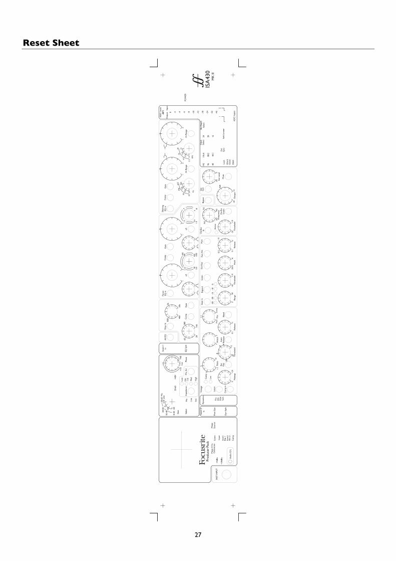
Reset Sheet
0-30
10-4
020-5
030
-60
Mic
120
600
1200
1.8
9 18
18
2.24.
7
1065
5
33
95
270
+40
+10
Inst
+25
MK
II
Ext
Leve
l
Mut
e
Aud
io O
/L
INST
INPU
T
+18d
Bu
+4dB
uM
ix Blen
d
Com
p
400
30-6
0
Inse
rt 2
Sour
ce
Inse
rt
Com
pRt
n 2
List
en
Rtn
1In
sert
Inpu
t
Met
er 0
Vu
Cal
ibra
tion
Met
er
Dyn
amic
s
Post
Dyn
In
Dyn
Spl
it
Post
Sum
Pre
EQ
Gai
n
Sele
ct-20
Mic
Impe
danc
e
Line
Inst
0-1
0
+10
Line
-8
Thre
shol
dM
akeu
p0
+20
-28
1.5
3
KeyExt
51:
1
-20
Ratio
10
+12
Rele
ase
0.1
7s
Rele
ase
Aut
o0
4FA
ttac
kS
Peak
EQ S
plit
Inse
rt 1
Mic
Air
+48V
Low
ISA Med
Hig
h
110
Phas
e60
20
300
1k6
All
EQIn
Filte
r In
800
Rele
ase
Gat
e
Thre
shol
dRa
nge
0-4
080
-20
Gat
e In
-30
Com
p
-15
-5
Expa
nd
-10
20m
SH
old
+10
4s0.
1
Ext
Key
List
enFa
st A
tt
0.3
Gat
e
22k5k
Para
mEQ
in
-x3
+-
+-
+-
+
40
200
400
0
Com
p
Ext
De-
Ess
Freq
uenc
y
List
enD
e-Es
s
Thre
shol
d-2
05s
+10
Act
ive
Hys
tIn
1.5
3k2
2k2
Out
put
-60
+6
7k2
Bypa
ss
9k2
Sum 0d
B
-60
Shel
ving
x3
0.6
0
3 6
160
56
460
Hz
20
EQ in
Com
pG
ate
Bit
Dep
thC
lock
Sele
ct
Wor
d
256X
Clo
ck
192 4896 Lo
ck
0
176.
4
44.1
88.2
Sync
Ext
AD
C In
puts
Sele
ct24 1620
Soft
Lim
iter
-32
-24
-18
12
-42
Hi R
ange
6.8
3.3
15
kHz
1.5
0
0
Hi R
ange
-6-4-2 -12
-10-8
0
Out
put
dBFS
Inpu
t
AD
C L
evel
POW
ER
ISA
430
List
en
Com
p In
Vint
age
Com
p
Lim
110
1.5
0+2
0
+10
Trim
27
Focusrite Distributors
AustraliaElectric Factory Pty Ltd.Phone: +61 3 9480 5988Fax: +61 3 9484 6708Email: [email protected]
AustriaTrius Vertrieb GmbH and Co KGPhone: +49 54 51 940 80Fax: +49 54 51 940 829Email: [email protected]
BelgiumAudio XL NVPhone: +32 11 232355Fax: +32 11 232172Email: [email protected]
BrazilPride MusicPhone: +55 11 6975-2711Fax: +55 11 6975-2772Email: [email protected]
BulgariaBulcomp LtdPhone: +35 932 652758Email: [email protected]
Canadac/o Digidesign (USA)Phone: +1 650 731 6300+1 866 FOCUSRITEFax: +1 650 731 6399Email: [email protected][email protected]
Croatia, Slovenia, Bosnia,Macedonia and SerbiaMusic ExportPhone: +49 89 746 123 90Fax: +49 89 746 123 92Email: [email protected]
CyprusTechnosoundPhone: +357 2 499971Fax: +357 2 499986Email: [email protected]
Czech RepublicMediaportPhone: +420 2 7173 5610Fax: +420 2 7273 4897Email: [email protected]
DenmarkNew Musik AGPhone: +45 86 190899Fax: +45 86 193199Email: [email protected]
EgyptAlpha AudioPhone: +202 245 6199Fax: +202 247 8969Email: [email protected]
FinlandStudiotec KyPhone: +358 9 5123 5330Fax: +358 9 5123 5355Email: [email protected]
FranceAudiopole (Tam Tam Audio)Phone: +33 1 45 144780Fax: +33 1 45 144790Email: [email protected]
GermanyTrius Vertrieb GmbH and Co KGPhone: +49 54 51 940 80Fax: +49 54 51 940 829Email: [email protected]
GreeceBon Studio S.A.Phone: +30 1 3809605-8Fax: +30 1 3827868Email: [email protected]
Hong Kong/ChinaDigital Media TechnologyPhone: +852 2721 0343Fax: +852 2366 6883Email: [email protected]
HungaryAbsolutePhone: +361 252 0196Fax: +361 341 0272Email: [email protected]
IcelandExtonPhone: +354 551 2555Fax: +354 562 6490Email: [email protected]
IndiaR & S ElectronicsPhone: +91 22 636 9147Fax: +91 22 636 9691Email: [email protected]
IndonesiaPT Santika Multi JayaPhone: +62 21 650 6040Fax: +62 21 650 880Email: [email protected]
IsraelSontronicsPhone: +972 3 570 5223Fax: +972 3 619 9297Email: [email protected]
ItalyGrisby Music ProfessionalPhone: +39 0 71 7108471Fax: +39 0 71 7108477Email: [email protected]
JapanAll Access IncPhone: +81 52 443 5537Fax: +81 52 443 7738Email: [email protected]
R. O. MaldivesIsland AcousticsPhone: +960 32 0032Fax: +960 31 8624Email: [email protected]
MexicoVari Internacional S.A. de C.V.Phone: +52 5605 9555Fax: +52 5605 9555Email: [email protected]
NetherlandsTotal Audio BVPhone: +31 20 4476447Fax: +31 20 4476464Email: [email protected]
New ZealandProtelPhone: +64 4 801 9494Fax: +64 4 384 2112Email: [email protected]
NorwayLydrommetPhone: +47 22 80 94 50Fax: +47 22 80 94 60Email: [email protected]
PolandMusic InfoPhone: +48 12 267 2480Fax: +48 12 267 2224Email: [email protected]
PortugalCaius TecnologiasPhone: +35 122 208 6009Fax: +35 122 208 5969Email: [email protected]
RomaniaA.F. Marcotec (Bucharest)Phone: +40 1 337 1254Fax: +40 1 337 1254Email: [email protected]
Russia, Baltics, UkraineAT TradePhone: +7 095 956 1105Fax: +7 095 956 6882Email: [email protected]
Singapore/MalaysiaTeam 108Phone: +65 748 9333Fax: +65 747 7273Email: [email protected]
SlovakiaCentronPhone: +421 264 780767Fax: +421 264 780042Email: [email protected]
South AfricaEltron Pty LtdPhone: +27 11 787 0355Fax: +27 11 787 9627Email: [email protected]
South KoreaBest Logic Sound Co.Phone: +82 2 515 7385Fax: +82 2 516 7385Email: [email protected]
SpainMedia Sys S.LPhone: +34 93 426 6500Fax: +34 93 424 7337Email: [email protected]
Sri LankaHiFi Centre LtdPhone: +94 1 580442Fax: +94 1 503174Email: [email protected]
SwedenPolysonic abPhone: +46 31 7069050Fax: +46 31 7069110Email: [email protected]
SwitzerlandBleuel Electronic agPhone: +41 1 751 7550Fax: +41 1 751 7500Email: [email protected]
TaiwanDigital Media Technology (DMT)(Taiwan) LtdPhone: +886 2 25164318Fax: +886 2 25159881Email: [email protected]
ThailandKECPhone: +66 2 222 8613/4Fax: +66 2 225 3173Email: [email protected]
United Arab EmiratesNMK Electronics Ent.Phone: +971 4626683Fax: +971 626682Email: [email protected]
United Kingdom & IrelandFocusrite Audio Engineering LtdPhone: +44 (0) 1494 462246Fax: +44 (0) 1494 459920Email: [email protected]
USADigidesignPhone: +1 630 731 6300+1 866 FOCUSRITEFax: +1 650 731 6399Email: [email protected][email protected]
VenezuelaAvcom C.A.Phone: +58 212 237 7762Fax: +58 212 237 8275Email: [email protected] VietnamVistarPhone: +84 4 824 3058Fax: +84 4 825 0099Email: [email protected]
Other territories not listed:Please contact Focusrite UnitedKingdom
28