Embed Size (px)
Citation preview

Introduction
Future wireless systems will be characterized by their heterogeneity - availability of multiple access systems in the same physical space.
Each system differs from others in terms of its capabilities - data rates, latencies, cost per byte etc.
Given such choice of systems, end users need not restrict themselves to any single system but rather at every instant, depending on their requirements choose the system or systems that best cater to his needs.

Example Scenario
A laptop is equipped with multiple interfaces. The applications running on it have bandwidth requirements higher than can be offered by any single system.
A solution is to aggregate the bandwidth offered by each of these different systems.
For example, if the different interfaces provide a bandwidth of 56kbps, 128kbps and 144kbps, the laptop has at its disposal an aggregated bandwidth of (56+128+144) = 328kbps.
The goal is to minimize the cost while satisfying the QOS requirements of the applications.

Other Scenarios
A corporate car fleet or rental cars equipped with multiple wireless interfaces. The multiple passengers have different profiles and
requirements and have to share the combined bandwidth of the interfaces among themselves.
An ad-hoc network formed by devices some of which are equipped with WWAN interfaces. The devices form the ad-hoc network with their WLAN
interface (bluetooth,802.11). The WWAN interfaces provide access to the internet and
the aggregated bandwidth is shared among themselves.

Laptop Scenario

Issues Involved
The multiple access systems display variable data rate, latency, packet loss.
These variations cause packet reordering. Buffering helps but it means increased delay. Situation only worsens when a reliable protocol
like TCP is used.

Approach
Problem can be addresses at different layers of the protocol stack- Network, Transport.
Network layer approach A single TCP/UDP connection end to end. Mobile IP like infrastructure Scheduler distributes the traffic to the multiple systems at the
network layer. Transport layer solution
Multiple TCP connections one for each access system being used. A scheduler distributes application data to the multiple TCP
connections. The connections can terminate at the home agent or correspondent
node.

Network Layer Solution - Scheduling Algorithm
Packets of different applications need to be scheduled onto the different links so that each application gets its share of bandwidth.
Care should be taken so that delay, reordering and jitter experienced by the packets is minimized.
Our approach is to use a Weighted Fair Queuing(WFQ) algorithm (that ensures that each application gets its share of bandwidth) and follow it with a channel striping algorithm.
WFQChannel
Striping Alg
App1
App2
App3
Link1
Link2
Link3
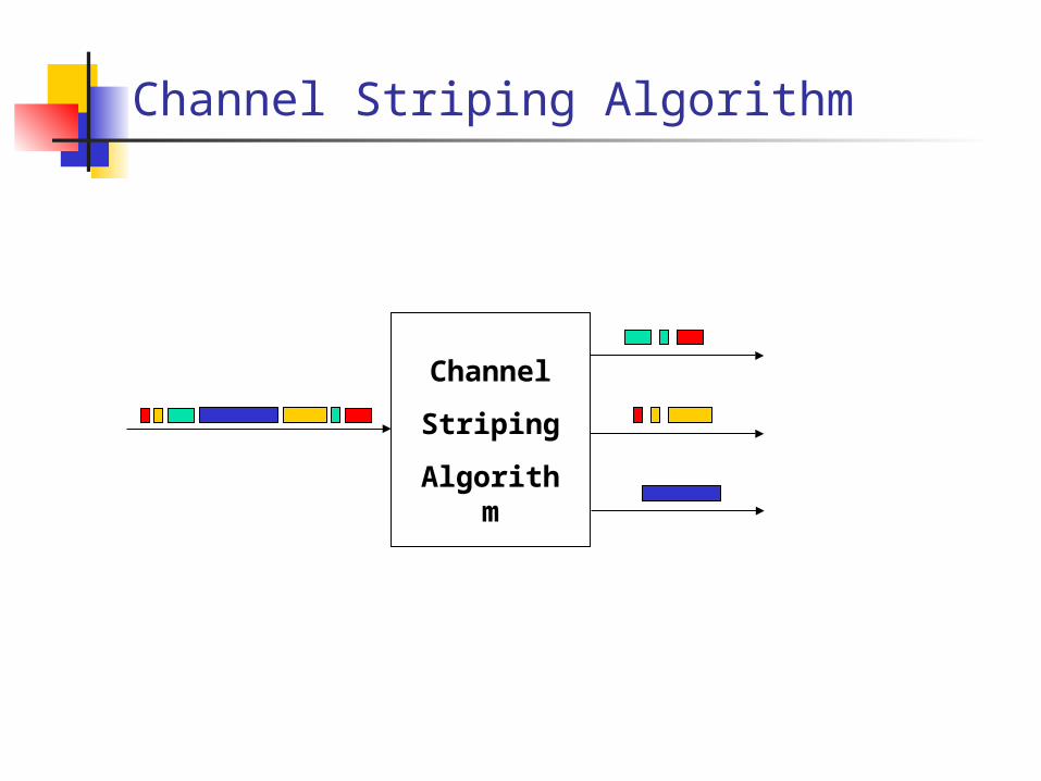
Channel Striping Algorithm
Channel
Striping
Algorithm

Channel Striping Algorithm: EDF
This algorithm schedules packets from a single input queue onto multiple links.
In our algorithm (which we call EDF), we schedule packets on the link which delivers it the earliest.
Each link l is associated with three quantities A variable S_l, which is the time the link becomes
available for the next transmission. D_l, the delay (estimated) associated with the link BW_l, the bandwidth (estimated) of the link
EDF cont..
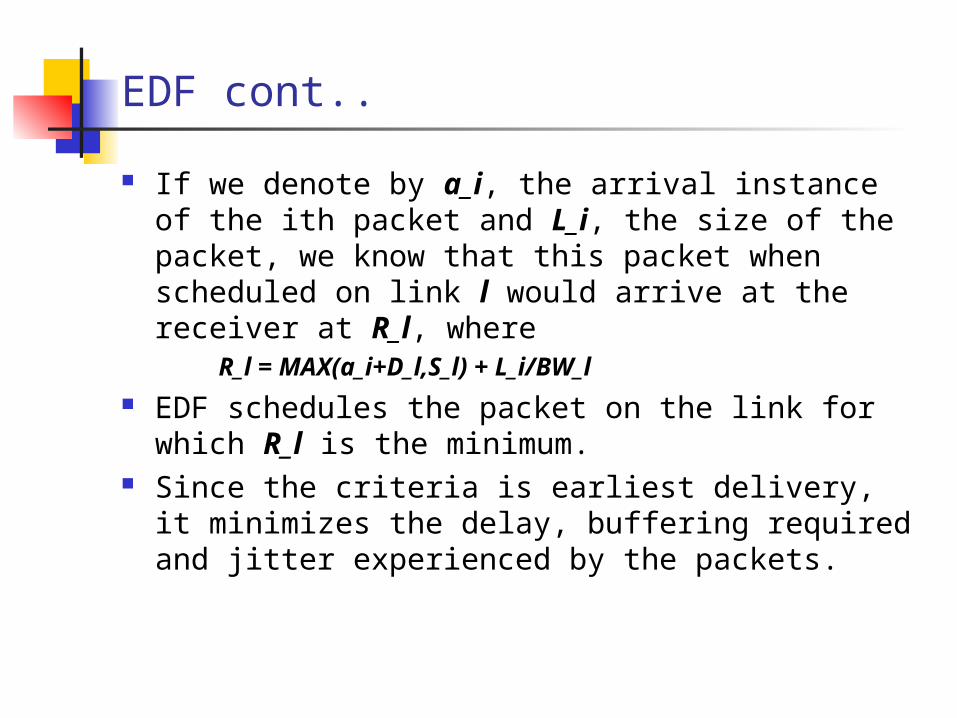
If we denote by a_i, the arrival instance of the ith packet and L_i, the size of the packet, we know that this packet when scheduled on link l would arrive at the receiver at R_l, where R_l = MAX(a_i+D_l,S_l) + L_i/BW_l
EDF schedules the packet on the link for which R_l is the minimum.
Since the criteria is earliest delivery, it minimizes the delay, buffering required and jitter experienced by the packets.

UDP Flows – Simulation Setup
WAN1
WAN1
WAN2
WAN2
WAN3
WAN3
Sender HomeAgent
MobileReceiver(Buffering)
HigherLayers
(10Mbps,20ms)
(350kbps,100ms)
(100kbps,120ms)
(50kbps,150ms)

Details of Setup
The sender generates packets according to an arrival and packet size distribution and forwards them to the home agent.
The scheduling algorithm in the home agent distributes the packets onto the multiple interfaces.
The WAN clouds induce delay according to a delay distribution.
The hop to the mobile receiver is wireless and has a limited bandwidth (bottleneck). Packets would be dropped according to a packet loss model.
The mobile receiver collects the packets and sends them in order to higher layers.

UDP Flows Cont…
We compare the performance of our algorithm with two other algorithms. A Single Link Algorithm (SL), where the multiple links
between the home agent and the mobile are replaced with a single link.
Surplus Round Robin which distributes traffic in proportion to the bandwidth.

Trace Driven Simulation
Source Details An MPEG1 video trace ( a cable TV show) 5000 frames Capture rate 25fps Mean bit rate – 440kbps, peak bit rate – 1760kbps 4 MTU sizes(bits) – 4000,8000,12000 and no restriction
Network details Constant and truncated Gaussian delay distribution with standard
deviation 50ms. No packet loss

Buffering Required – constant delay

Buffering Required – variable delay
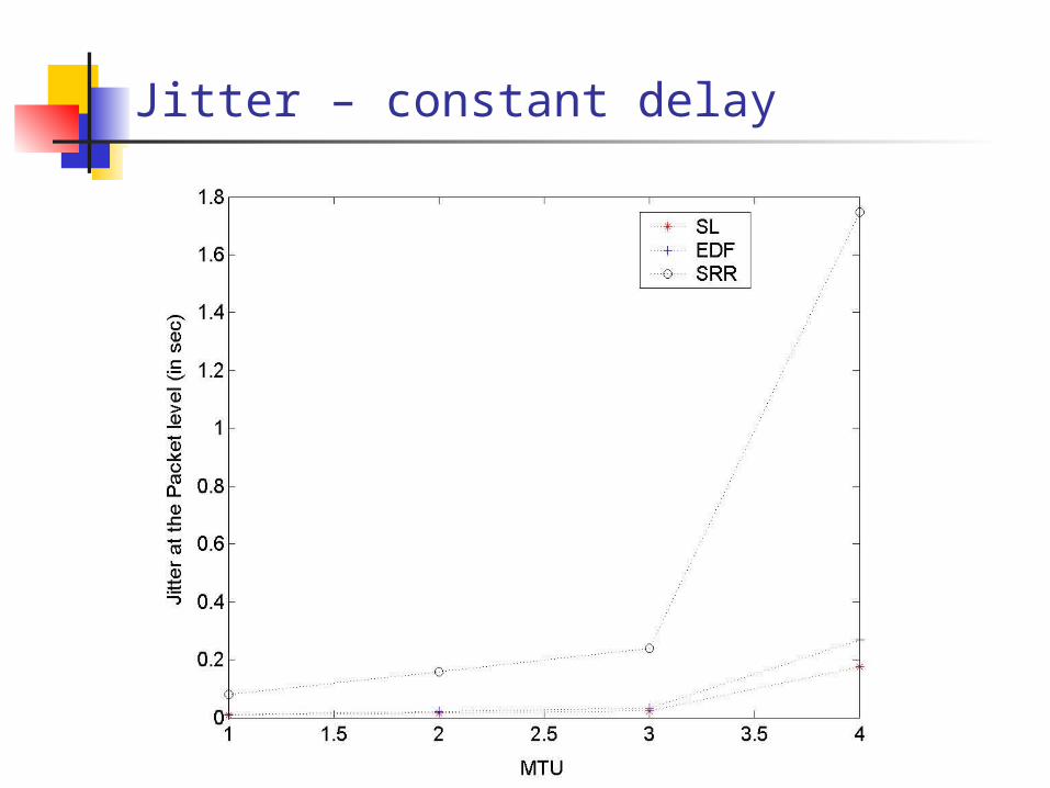
Jitter – constant delay

Jitter – variable delay

TCP Flows – Details
Same setup as before except the protocol used is TCP.
Application - File transfer of 2 Mbytes Download time is measured Two scenarios considered
The packets are passed to TCP layer as they arrive. The packets are buffered and passed in order to TCP
layer

Download time (No buffering)
Algorithm Constant Delay
Variable
Delay
SL (500kbps) 33.4 69.9
EDF 33.6 140.9
SRR 111.4 177.0
SL (350kbps) 48.6 71.9

Future Work
UDP flows – evaluate the performance of the system with packet loss and rate control.
TCP flows Buffering at the receiver Opening multiple TCP connections
Multiple Applications using different protocols (UDP,TCP) , having different QoS requirements sharing the aggregated bandwidth.
Multiple users sharing the aggregated bandwidth. Effect of incorrect estimation of the delay and bandwidth
on EDF.