Embed Size (px)
Citation preview

University of WollongongResearch Online
Faculty of Engineering and Information Sciences -Papers: Part A Faculty of Engineering and Information Sciences
2011
Introduction - A review of membrane reactorsFausto GallucciUniversity of Calabria
Angelo BasileEindhoven University of Technology
Faisal Ibney HaiUniversity of Wollongong, [email protected]
Research Online is the open access institutional repository for the University of Wollongong. For further information contact the UOW Library:[email protected]
Publication DetailsGallucci, F., Basile, A. & Hai, F. Ibney. (2011). Introduction - A review of membrane reactors. In A. Basile & F. Gallucci (Eds.),Membranes for membrane reactors: preparation, optimization and selection (pp. 1-61). United Kingdom: John Wiley & sons.
Introduction - A review of membrane reactors
AbstractIn the last decades, membrane catalysis has been studied by several research and the significant progress in thisfield is summarized in several review articles (Armor 1998, Lin 2001, Lu 2007, Mcleary 2006, Sanchez 2002,Saracco 1994, Shu 1991). Considering a IUPAC definition (Koros 1996), a membrane reactor (MR) is adevice for simultaneously performing a reaction (steam reforming, dry reforming, autothermal reforming,etc.) and a membrane-based separation in the same physical device. Therefore, the membrane not only playsthe role of a separator, but also takes place in the reaction itself. The term Membrane Bioreactor (MBR), onthe other hand, refers to the coupling of biological treatment with membrane separation in contrast to thesequential application of membrane separation downstream of classical biotreatment ( Judd 2008,Visvanathan 2000). This chapter comprises a review of both MR (section 1-4) and MBR (section 5).
Keywordsintroduction, membrane, review, reactors
DisciplinesEngineering | Science and Technology Studies
Publication DetailsGallucci, F., Basile, A. & Hai, F. Ibney. (2011). Introduction - A review of membrane reactors. In A. Basile & F.Gallucci (Eds.), Membranes for membrane reactors: preparation, optimization and selection (pp. 1-61).United Kingdom: John Wiley & sons.
This book chapter is available at Research Online: http://ro.uow.edu.au/eispapers/1153

Gallucci, F., Basile, A. and Hai, F. I. "Introduction—A review of Membrane reactors" in Membranes for membrane reactors: Preparation, Optimization and Selection (eds. Basile, A., Gallucci, F.), page 1-62, Wiley InterScience, USA, 2011.
1
Introduction – A review on membrane reactors
Fausto Gallucci2, Angelo Basile1, Faisal Ibney Hai3
1. Chemical Process Intensification, Faculty of Chemical Engineering and Chemistry, Eindhoven University of Technology, PO Box 513, 5600 MB, Eindhoven, The Netherlands
2. Institute on Membrane Technology, ITM-CNR c/o University of Calabria via P. Bucci, cubo 17/C 87030 Rende (CS, Italy)
3. Environmental Engineering, The University of Wollongong, Northfields Ave, NSW 2522, Australia
Introduction
In the last decades, membrane catalysis has been studied by several research and the significant
progress in this field is summarized in several review articles (Armor 1998, Lin 2001, Lu 2007,
Mcleary 2006, Sanchez 2002, Saracco 1994, Shu 1991).
Considering a IUPAC definition (Koros 1996), a membrane reactor (MR) is a device for
simultaneously performing a reaction (steam reforming, dry reforming, autothermal reforming,
etc.) and a membrane-based separation in the same physical device. Therefore, the membrane not
only plays the role of a separator, but also takes place in the reaction itself. The term Membrane
Bioreactor (MBR), on the other hand, refers to the coupling of biological treatment with
membrane separation in contrast to the sequential application of membrane separation
downstream of classical biotreatment (Judd 2008, Visvanathan 2000). This chapter comprises a
review of both MR (section 1-4) and MBR (section 5).
1. Membranes for MR
The membranes can be classified according to their nature, geometry and separation regime. In
particular, they can be classified into organic, inorganic and organic/inorganic hybrids.

Gallucci, F., Basile, A. and Hai, F. I. "Introduction—A review of Membrane reactors" in Membranes for membrane reactors: Preparation, Optimization and Selection (eds. Basile, A., Gallucci, F.), page 1-62, Wiley InterScience, USA, 2011.
2
The choice of membrane type to be used in MRs depends on parameters such as the productivity,
separation selectivity, membrane life time, mechanical and chemical integrity at the operating
conditions and, particularly, the cost.
The discovery of new membrane materials was the key factor for increasing the application of
the membrane in the catalysis field. The significant progress in this area is reflected in an
increasing number of scientific publications, which have grown exponentially over the last few
years, as recently shown by McLeary et al. (2006).
Generally, the membranes can be even classified into homogenous or heterogeneous, symmetric
or asymmetric in structure, solid or liquid; they can possess a positive or negative charge as well
as they can be neutral or bipolar. In all cases, a driving force as a gradient of pressure,
concentration, etc., is applied in order to induce the permeation through the membrane.
Thus, the membranes can be categorized according to their nature, geometry and separation
regime (Khulbe 2007).
The first classification is by their nature, which distinguishes the membranes into biological and
synthetic ones, which differ completely for functionality and structure. Biological membranes
are easy to manufacture, but present many disadvantages such as limited operating temperature
(below 100 °C), limited pH range, drawbacks related to the clean-up, susceptibility to microbial
attack due to their natural origin (Xia 2003).
Synthetic membranes can be subdivided into organic (polymeric) and inorganic (ceramic, metal)
ones. Polymeric membranes commonly operate between 100 – 300 °C (Catalytica 1988),
inorganic ones above 250 °C. Moreover, inorganic membranes show both wide tolerance to pH
and high resistance to chemical degradation. Referring to the organic membranes, it can be said

Gallucci, F., Basile, A. and Hai, F. I. "Introduction—A review of Membrane reactors" in Membranes for membrane reactors: Preparation, Optimization and Selection (eds. Basile, A., Gallucci, F.), page 1-62, Wiley InterScience, USA, 2011.
3
that the majority of the industrial membrane processes are made from natural or synthetic
polymers. Natural polymers include wool, rubber (polyisoprene) and cellulose, whereas synthetic
polymers include polyamide, polystyrene and polytetrafluoroethylene (Teflon).
In the viewpoint of the morphology and/or membrane structure, the inorganic membranes can be
even subdivided into porous and metallic. In particular, as indicated by IUPAC (Koros 1996)
definition, porous membranes can be classified according to their pore diameter: microporous
(dp < 2nm), mesoporous (2nm < dp < 50nm) and macroporous (dp > 50nm).
Metallic membranes can be categorized into supported and unsupported ones. Supported dense
membranes offer many advantages unmatched by the porous ceramic membranes. In particular,
many efforts were devoted to develop dense metallic layers deposited on a porous support
(alumina, silica, carbon and zeolite) for separating hydrogen with a non-complete perm-
selectivity, but lowering the costs related to the dense metallic membranes. In fact, the kind of
membranes based on palladium and its alloy is used for gas separation and in MR field for
producing pure H2 (Lin 2001) and presents as main drawback the high cost.
1.1 Polymeric membranes
Basically, all polymers can be used as membrane material but, owing to a relevant difference in
terms of their chemical and physical properties, only a limited number of them is practically
utilized. In fact, the choice of a given polymer as a membrane material is not arbitrary, but based
on specific properties, originating from structural factors. Ozdemir et al. (2006) gives an
overview of the commercial polymers used as membranes as well as of other polymers having
high potentially for application as a membrane material. However, many industrial processes
involve operations at high temperatures. In this case, polymeric membranes are not useful and,
therefore, inorganic ones are preferred.

Gallucci, F., Basile, A. and Hai, F. I. "Introduction—A review of Membrane reactors" in Membranes for membrane reactors: Preparation, Optimization and Selection (eds. Basile, A., Gallucci, F.), page 1-62, Wiley InterScience, USA, 2011.
4
1.2 Inorganic membranes
Inorganic membranes are commonly constituted by different materials as ceramic, carbon, silica,
zeolite, oxides (alumina, titania, zirconia) as well as palladium, silver etc. and their alloys.
They can operate at elevated temperatures. In fact, they are stable at temperatures ranging from
300 – 800 ºC and in some cases (ceramic membranes) usable over 1000 ºC (Van Veen 1996).
They present also high resistance to chemical degradation. As previously said, the inorganic
membranes present a high cost as main drawback.
Table 1 sketches the most important advantages and disadvantages of inorganic membranes with
respect to the polymeric ones.
So, although inorganic membranes are more expensive than the polymeric ones, they possess
advantage such as resistance towards solvents, well-defined stable pore structure (in the case of
porous inorganic membranes), high mechanical stability and elevated resistance at high operating
temperatures.
1.2.1 Metal membranes
Conventionally, dense metal membranes are used for hydrogen separation from gas mixtures and
in MR area. Palladium and its alloys are the dominant materials for preparing this kind of
membranes due to its high solubility and permeability of hydrogen. Unfortunately, owing to the
low availability of palladium in the nature, it results to be very expensive. Recently, supported
thin metallic membranes are realized by coating a thin layer of palladium (showing thickness
ranging from submicron to few microns) on a ceramic support. In this case, the advantages
include reduced material costs, improved resistance to mechanical strength and higher
permeating flux.

Gallucci, F., Basile, A. and Hai, F. I. "Introduction—A review of Membrane reactors" in Membranes for membrane reactors: Preparation, Optimization and Selection (eds. Basile, A., Gallucci, F.), page 1-62, Wiley InterScience, USA, 2011.
5
Otherwise, dense membranes selectively permeable only to hydrogen based on tantalum,
vanadium, nickel and titanium are considered valid and less expensive alternative with respect to
the palladium and its alloy.
A problem associated with metal membranes is the surface poisoning, which can be more
significant for thin metal membranes. The influence of poisons such as H2S or CO on Pd-based
membranes is a serious problem. These gases are adsorbed on the palladium surface blocking
available dissociation sites for hydrogen. The effect of small amounts of H2S may be minimized
by operating at higher temperature or by using a protective layer of platinum. CO can easily
desorb at operating temperatures above 300 °C (Amandusson 2000).
1.2.2 Ceramic membranes
These membranes are made from aluminium, titanium or silica oxides. They show as advantages
of being chemically inert and stable at high temperatures. This stability makes ceramic
microfiltration and ultrafiltration membranes particularly suitable for food, biotechnology and
pharmaceutical applications in which membranes require repeated steam sterilization and
chemical cleaning. Ceramic membranes have been also proposed for gas separation as well as for
application in MRs.
However, some problems remain to be solved: difficulties in proper sealing of the membranes in
modules operating at high temperature, extremely high sensitivity of membranes to temperature
gradient leading to membrane cracking, chemical instability of some perovskite-type materials.
1.2.3 Carbon membranes
Carbon molecular sieve (CMS) membranes have been identified as very promising candidates
for gas separation, both in terms of separation properties and stability. CMS are porous solids
containing constricted apertures that approach the molecular dimensions of diffusing gas
Gallucci, F., Basile, A. and Hai, F. I. "Introduction—A review of Membrane reactors" in Membranes for membrane reactors: Preparation, Optimization and Selection (eds. Basile, A., Gallucci, F.), page 1-62, Wiley InterScience, USA, 2011.
6
molecules. As such, molecules with only slight differences in size can be effectively separated
through molecular sieving (Fuertes 1998).
CMS membranes can be obtained by pyrolysis of many thermosetting polymers such as
poly(vinylidene chloride) or PVDC, poly(furfural alcohol) or PFA, cellulose triacetate,
polyacrylonitrile or PAN and phenol formaldehyde and carbon membranes can be divided into
two categories: supported and unsupported.
1.2.4 Zeolite membranes
Zeolites are microporous crystalline alumina-silicate with an uniform pore size. Zeolites are used
as catalysts or adsorbents in a form of micron or submicron-sized crystallites embedded in
millimeter-sized granules.
One of the main drawbacks related to these membranes is represented by their relatively low gas
fluxes compared to other inorganic membranes. Moreover, another important problem is
represented by the zeolites thermal effect. The zeolite layer can exhibit negative thermal
expansion, i.e. in the high temperature region the zeolite layer shrinks, but the support
continuously expands, resulting in thermal stress problems for the attachment of the zeolite layer
to the support as well as for the connection of the individual micro-crystals within the zeolite
layer (Cejka).
1.3 Membrane housing
Concerning the applications of both organic and inorganic membranes, several configurations are
conventionally used for the membrane housing. Generally, a modular configuration (parallel, in
series and so on) may be combined for producing the desired effect. Membrane housing provides
support and protection against operating pressures. Plate-and-frame, spiral wound, tubular and

Gallucci, F., Basile, A. and Hai, F. I. "Introduction—A review of Membrane reactors" in Membranes for membrane reactors: Preparation, Optimization and Selection (eds. Basile, A., Gallucci, F.), page 1-62, Wiley InterScience, USA, 2011.
7
hollow fiber systems are the most common membrane housing configurations. The advantages
and disadvantages of the different membrane elements are listed in Table 2.
1.4 Membrane separation regime
Mass transport through porous and dense membranes occurs with different mechanisms. In
porous membranes, molecular transport occurs depending on the membrane properties. In
particular, macroporous materials, such as α–alumina, provide no separating function and are
mainly used to create controlled dosing of a reactant or to support a dense or mesoporous
separation layer. Transport through mesoporous membranes, such as Vycor glass or γ–alumina,
is governed by Knudsen diffusion. These membranes are used as composite membranes with
macroporous support materials. Microporous membranes, such as carbon molecular sieves,
porous silica and zeolites, offer higher separation factors due to their molecular sieving effect.
1.4.1 Porous membrane
The different transport mechanisms in porous membranes are presented below:
Poiseuille (viscous) mechanism (Figure 1) This mechanism occurs when the average pore
diameter is bigger than the average free path of fluid molecules. In this case, no separation takes
place (Saracco 1994). Knudsen mechanism (Figure 2) When the average pore diameter is similar
to the average free path of fluid molecules, Knudsen mechanism takes place. In this case, the
flux of the component through the membrane is calculated by means of the following equation
(Saracco 1994):
i
ii
p
TRM2
GJ (1.1)

Gallucci, F., Basile, A. and Hai, F. I. "Introduction—A review of Membrane reactors" in Membranes for membrane reactors: Preparation, Optimization and Selection (eds. Basile, A., Gallucci, F.), page 1-62, Wiley InterScience, USA, 2011.
8
Surface diffusion (Figure 3) This mechanism is achieved when one of the permeating molecules
is adsorbed on the pore wall. This type of mechanism can reduce the effective pore dimensions
obstructing the transfer of different molecular species (Kapoor 1989).
Capillary condensation (Figure 4) When one of the component condenses within the pores due
to capillary forces, this type of mechanism takes place. Generally, the capillary condensation
favours the transfer of relatively large molecules (Lee 1986). Multi-layer diffusion (Figure 5)
When the molecule-surface interactions are strong multi-layer diffusion occurs. This mechanism
is like to an intermediate flow regime between surface diffusion and capillary condensation
(Ulhorn 1992). Molecular Sieving (Figure 6) It takes place when pore diameters are very small,
allowing the permeation of only the smaller molecules.
1.4.2 Dense metallic membranes
In dense metallic membranes, molecular transport occurs through a solution-diffusion
mechanism. In particular, in a dense palladium-based membrane, hydrogen atoms interact with
palladium metal. Hydrogen permeation through the membrane is a complex process with several
stages:
dissociation of molecular hydrogen at the gas/metal interface,
adsorption of the atomic hydrogen on membrane surface;
dissolution of atomic hydrogen into the palladium matrix;
diffusion of atomic hydrogen toward the opposite side;
re-combination of atomic hydrogen to form hydrogen molecules at the gas/metal
interface;
desorbtion of hydrogen molecules.

Gallucci, F., Basile, A. and Hai, F. I. "Introduction—A review of Membrane reactors" in Membranes for membrane reactors: Preparation, Optimization and Selection (eds. Basile, A., Gallucci, F.), page 1-62, Wiley InterScience, USA, 2011.
9
At a fixed temperature, the hydrogen permeation flux through a dense palladium membrane can
be expressed by means of following relation (1.2):
JH2 = PeH2 (pn
H2,ret pnH2,perm)/δ (1.2)
where: JH2 is the hydrogen flux through the membrane; PeH2 the hydrogen permeability; δ the
membrane thickness; pH2,ret and pH2,perm the hydrogen partial pressures at the retentate and
permeate sides, respectively, and n (in the range 0.5–1) is the dependence factor of the hydrogen
flux on the hydrogen partial pressure.
When the pressure is relatively low (Shu 1991), n = 0.5 and the relation (1.2) becomes Sieverts-
Fick law (1.3):
JH2,Sieverts = PeH2 · (p0.5
H2,ret p0.5H2,perm)/δ (1.3)
The thickness of a dense palladium membrane is very important because it represents a
compromise between two factors. On one hand, a thinner membrane offers less flow resistance
and, hence, a higher permeability. On the other hand, practical fabrication technology limits the
thickness of the membrane with respect to mechanical integrity and strength.
Moreover, palladium alloys are preferred over pure palladium for two reasons. Firstly, the
hydrogen permeability of some palladium alloys is higher than those of pure palladium.
Secondly, pure palladium can become brittle after different thermal and hydrogenation cycles.
The choice of alloying other different metals to the palladium has been studied, for example, by
Hwang et al. (1975). The authors found that the palladium alloyed show different hydrogen
fluxes depending on the metal content, Figure 7.
2. Salient features of Membrane reactors

Gallucci, F., Basile, A. and Hai, F. I. "Introduction—A review of Membrane reactors" in Membranes for membrane reactors: Preparation, Optimization and Selection (eds. Basile, A., Gallucci, F.), page 1-62, Wiley InterScience, USA, 2011.
10
As already said, a membrane reactor combines the chemical reaction and gas separation. The
significant progress in the field of MRs is reflected in the increasing number of publications as
shown in Figure 8.
Many heterogeneous gas–solid catalytic processes of industrial relevance (conventionally carried
out using fixed, fluidised or trickle bed reactors) involve the combination of operations at high
temperatures and in chemically harsh ambient. For these two factors, inorganic membranes are
favourite over polymeric materials.
A MR can show flat (Figure 9) or tubular geometry (Figure 10). In tubular MR, the density of
packed bed could be improved using multichannel tubular monoliths and depositing the catalyst
inside the pores.
Generally, the MRs can be also sub-divided as reported below (and in Figure 10):
catalytic membrane reactors (CMR);
packed bed membrane reactors (PBMR);
catalytic non-permselective membrane reactors (CNMR),
non-permselective membrane reactors (NMR);
reactant-selective packed bed reactors (RSPBR).
2.1 Applications of membrane reactors
Membrane reactors are mainly used to carry out the reactions limited by the equilibrium
conversion such as water gas shift and so on. In fact, in a MR the separation capability of a
membrane is utilized to improve the performance of a catalytic system. Usually, there are two
main generic approaches: selective product separation (Extractor) and selective reactant addition
(Distributor), as shown in Figure 11 (Julbe 2001a). The first MR type facilitates the in–situ
removal of one of the products (Figure 11.a). For example, for steam reforming reactions, H2

Gallucci, F., Basile, A. and Hai, F. I. "Introduction—A review of Membrane reactors" in Membranes for membrane reactors: Preparation, Optimization and Selection (eds. Basile, A., Gallucci, F.), page 1-62, Wiley InterScience, USA, 2011.
11
yield and CO2 product selectivity in TRs are limited by Thermodynamics. By selective removal
of H2 from the reaction side, the thermodynamic equilibrium restrictions can be overcome. Due
to the shift effect, both high H2 yields and high CO2 selectivities can be achieved. Moreover, this
effect allows operation at milder reaction conditions in terms of temperature and pressure
(Zaman 1994).
The second kind of MR uses the membrane to control the contact within reactants (Figure 11.b).
Both a permselective and a non-permselective membranes can be used to feed distributively one
of the reactants. For partial oxidation reactions in TRs, O2 rich feed results in low product
selectivity and high reactant conversions. On the contrary, low oxygen content feed results in
high product selectivity but lower conversions. Using a membrane for distributive feeding of O2
along the axial coordinate of the catalytic bed, both high reactant conversions and high product
selectivities can be combined (Bredesen 2004, Coronas 1999, Julbe 2001a, Saracco 1999). An
additional advantage of this approach is that the reactant (hydrocarbon) and O2 feeds are not
premixed and, hence, the possibility of realizing mixtures as well as the flame back firing into
the feed lines are greatly reduced. Moreover, the feed distribution can represent a promising
approach for fast reactions.
2.2 Advantages of the membrane reactors
With respect to TRs, a MR permits the improvement of the performances in terms of reaction
conversion, products selectivity, and so on. In fact, by means of the so-called “shift effect”, the
thermodynamic equilibrium restrictions can be overcome. At least, MRs behaviour could be the
same of a TR working at the same MRs operating conditions.
Keizer et al. (1994) studied the performances of several MRs using different kind of membranes.
As reported in Figure 12, they represent the dependence of the cyclohexane conversion as a

Gallucci, F., Basile, A. and Hai, F. I. "Introduction—A review of Membrane reactors" in Membranes for membrane reactors: Preparation, Optimization and Selection (eds. Basile, A., Gallucci, F.), page 1-62, Wiley InterScience, USA, 2011.
12
function of the parameter H, defined as permeation to reaction ratio and considering the
Damköhler number (Da) equal to 1. The line with H = 0 represents a TR, while other lines
correspond to a different type of MRs. In particular, lines 1-2 refer to MRs governed by Knudsen
transport mechanisms; lines 3-4 refer to microporous MRs and lines 5-6 refer to dense ones. Two
regions can be distinguished. The first one corresponds to low permeation to reaction rate ratios.
In this region, microporous MRs show the same behaviors of dense and mesoporous ones.
However, the performance of each MR types in terms of conversion is better than the TRs ones.
At higher H-values, the difference in the MRs properties are visible. MRs with a finite separation
factor show an optimum permeability/reaction rate region. Above optimum the reactant loss due
to permeation induces a detrimental effect on the conversion. The higher the separation the
higher the conversion in this optimum region. MRs with infinite separation factors for hydrogen
do not show this conversion drawback since no loss of reactants occurs. Thus, they maintain the
conversion at a high value.
As shown, this kind of membranes represents an important issue concerning the MR
performances in terms of conversion, hydrogen selectivity, etc.
Thus, the main advantage of using MRs is represented by the combination of reaction and
hydrogen separation, leading to a reduction of capital cost and better reactor performances.
Moreover, they allow also controlling additions of reactants and coupling of reactions (Saracco
1994).
3. Hydrogen production by membrane reactors
The world economy is mainly based on the exploitation of fossil fuels (oil, coal and methane)
(Moriarty 2007), according to data provided by International Energy Agency reported in Figure
13. In particular, the primary energy source is oil, but owing to the decrease of its reserves and to

Gallucci, F., Basile, A. and Hai, F. I. "Introduction—A review of Membrane reactors" in Membranes for membrane reactors: Preparation, Optimization and Selection (eds. Basile, A., Gallucci, F.), page 1-62, Wiley InterScience, USA, 2011.
13
the increase of the environmental pollution due to emissions of CO2 and other greenhouse gases
(in the world, more than 75.0% of CO2 emissions comes from burning of fossil fuels and, in the
last 70 years, more than 30.0% of CO2 increment as volume percentage was registered in the
atmosphere (Marbàn 2007)), it is strongly necessary to develop new technologies as well as to
exploit renewable materials as alternative to the derived fossil fuels.
For example, fuel cells have been identified as one of the most promising technologies for the
future clean energy industry (Stambouli 2002). They can be applied to large-scale stationary
systems for distributed power generation as well as for small-scale portable power supplying
devices for micro-electronic equipment and auxiliary power units in vehicles (Wee 2007).
Compared to other types of fuel cells, PEMFCs generate more power for a given volume or
weight of fuel cell. This high-power density characteristic makes them compact and lightweight.
PEMFCs are fed by pure hydrogen and only few ppm of CO (<10) may be tolerated by the
anodic Pt catalysts. For this reason, it is strictly necessary to use a pure or at least CO-free
hydrogen stream for feeding a PEM fuel cell.
Industrially, hydrogen is produced in fixed bed reactors by means of reforming reactions of fossil
fuels such as natural gas, gasoline, etc. Nevertheless, as previously mentioned, in order to solve
the problems related to the environmental pollution, it is necessary the exploitation of renewable
materials. Therefore, hydrogen could be produced using “clean” fuels (Goltsov 2001).
The steam reforming reaction is conventionally carried out in fixed bed reactors and produces a
stream containing hydrogen with other byproduct gases like mainly CO, CH4 and CO2.
Therefore, in the viewpoint of feeding a PEMFC, hydrogen needs to be purified by means of the
following processes: water gas shift (WGS) reaction, pressure swing adsorption and/or Pd
membrane separation, etc. Otherwise, it could be economically more advantageous to use a

Gallucci, F., Basile, A. and Hai, F. I. "Introduction—A review of Membrane reactors" in Membranes for membrane reactors: Preparation, Optimization and Selection (eds. Basile, A., Gallucci, F.), page 1-62, Wiley InterScience, USA, 2011.
14
hydrogen perm-selective MR, able to both carry out the reaction and remove pure hydrogen in
the same device (Basile 2008a, Cheng 2002, Damle 2009, Matsumura 2008, Tosti 2000, Valenti
2008). In particular, with respect to the traditional reactors (TRs), MRs are able:
to combine chemical reaction and hydrogen separation in only one system reducing the
capital costs;
to conversion enhancement of equilibrium limited reactions;
to achieve higher conversions than TRs, operating at the same MR conditions, or the
same conversion, but operating at milder conditions;
to improve yield and selectivity.
Moreover, as previously said, the most useful membranes offering a complete hydrogen perm-
selectivity are the dense palladium-based ones (Lu 2007). The transport mechanism related to the
hydrogen permeation through a dense Pd-based membrane is the solution/diffusion (Ward 1999).
Generally, when a dense Pd membrane is exposed to a hydrogen stream at low temperatures (<
300 °C), the embrittlement phenomenon takes place owing to the various typologies of
expansion of the reticular constants in the Pd-H systems. A possible solution is represented by
alloying palladium with elements, such as silver or copper, in order to obtain Pd-H phases with
increased reticular step and able of anticipating the reticular expansion from hydrogen (Hou
2003).
Since 1960s, hydrogen production by MRs has been mainly studied using dense Pd-based
membranes and microporous silica membranes. Pd membranes for H2 production overcome all
the other candidate materials due to of the very high solubility of H2 in pure Pd (Figure 14) and
for their infinite perm-selectivity to H2.

Gallucci, F., Basile, A. and Hai, F. I. "Introduction—A review of Membrane reactors" in Membranes for membrane reactors: Preparation, Optimization and Selection (eds. Basile, A., Gallucci, F.), page 1-62, Wiley InterScience, USA, 2011.
15
In particular, Pd adsorbs 600 times its volume of H2 at room temperature (Julbe 2001b). For this
characteristics, Pd or Pd alloys on metallic or ceramic supports have been widely studied
(Amandusson 2001, Dittmeyer 2001, Kikuchi 2000, Li 1993, , Paturzo 2002, Roa 2003, Shu
1996, Tong 2005a, Tosti 2003 Uemiya 1991,Wang 2004, Zhang 2006).
Therefore, as stated in the first part of this paragraph, it is very interesting to investigate the
production of hydrogen by means reforming reaction of renewable sources, using the innovations
connected to the MRs. However, in the following a small overview is presented on the hydrogen
production based on the classic processes such as methane steam reforming, methane dry
reforming and partial oxidation of methane as well as water gas shift reaction coupled with the
use of membrane reactors.
3.1.1 Methane steam reforming
Conventionally, hydrogen is produced by exploiting methane as a derived fossil-fuel in
reforming reactions. Currently, 80.0–85.0% of the world wide hydrogen supplying is produced
by methane steam reforming (SRM) (3.1.1.1) reaction in fixed bed reactors (Simpson 2007).
CH4 + 2H2O ⇆ 4H2 + CO2 H°298 K = 165.0 kJ/mol
(3.1.1.1)
Alternatively, methane could be renewably obtained via biogas generated by the fermentation of
organic matter including manure, wastewater sludge, municipal solid waste (including landfills)
or any other biodegradable feedstock, under anaerobic conditions. The composition of biogas
varies depending on the origin of the anaerobic digestion process. Advanced waste treatment
technologies can produce biogas with 55.0 – 75.0% of CH4 using in situ purification techniques
(Richards 1994).
However, most part of the specialized literature on SRM area is devoted to study the optimal
reaction conditions and the most adequate catalyst usable during the reaction in TRs.

Gallucci, F., Basile, A. and Hai, F. I. "Introduction—A review of Membrane reactors" in Membranes for membrane reactors: Preparation, Optimization and Selection (eds. Basile, A., Gallucci, F.), page 1-62, Wiley InterScience, USA, 2011.
16
In the last decades, the alternative technology of the membrane reactors has been applied to SRM
reaction in order to produce hydrogen with the advantages previously reported in this work. In
particular, recent reviews regarding the state-of the-art on the hydrogen production via SRM
reaction performed by MRs have been published (Ritter 2007, Barelli 2008). Moreover, different
scientific papers deal on various MRs (based mainly on dense palladium and its alloy
membranes) for hydrogen production by SRM reaction (Chen 2008, Gallucci 2008c, Haag 2007,
, Tong 2005b, Tsuru 2006a).
3.1.2 Dry reforming of methane
Another approach for hydrogen production in MRs is the dry reforming of methane (3.1.2.1):
CH4 + CO2 = 2CO + 2H2 H°298 K= +247.0 kJ/mol (3.1.2.1)
In particular, methane dry reforming reaction could reduce the amount of greenhouse gases
present in the atmosphere. An important limitation for making the methane dry reforming a
commercially viable reaction using TRs is due to Thermodynamics, which limits the conversion.
Nevertheless, in a MR, methane (and carbon dioxide) conversion can be increased though the
reaction products (or preferentially only hydrogen) are selectively removed from the reaction
side.
Gallucci et al. (2008) performed the dry reforming reaction in both TR and MR with the aim of
consuming carbon dioxide and producing hydrogen. Moreover, by using the dense Pd membrane
reactor, the carbon deposition on the catalyst is drastically reduced and a CO-free hydrogen
stream is produced. At 450 °C, the maximum CO2 conversion obtained in the MR was around
20.0% versus 14.0% achieved in the TR.

Gallucci, F., Basile, A. and Hai, F. I. "Introduction—A review of Membrane reactors" in Membranes for membrane reactors: Preparation, Optimization and Selection (eds. Basile, A., Gallucci, F.), page 1-62, Wiley InterScience, USA, 2011.
17
Haag et al. (2007) studied the methane dry reforming reaction in a composite MR, where the
membrane was constituted of a thin, catalytically inactive nickel layer, deposited by electroless
plating on asymmetric porous alumina with acceptable hydrogen perm-selectivity at high
temperature. Ferreira et al. (2002) analyzed the applicability of mesoporous ceramic filters in a
MR to carry out the dry reforming of methane with carbon dioxide. 3.1.3 Partial oxidation of
methane
Both steam reforming and dry reforming of methane are endothermic reactions. On the contrary,
the partial oxidation of methane (POM) (3.1.3.1) is an exothermic reaction, in which the main
drawback in TRs is represented by the Thermodynamics. For example, the pressure increase
gives a decrease in equilibrium methane conversions
CH4 + 1/2O2 = CO + 2H2 H°298 K= -36.0 kJ/mol (3.1.3.1)
Therefore, a MR allows these thermodynamic limitations to be overcome, reaching a high
methane conversion at low temperature with respect to a TR.
By using a dense Pd-based MR with respect to a TR exercised at same conditions, Basile et al.
(2001a, 2001b) stated that:
• the methane conversion is remarkably higher in MRs than in the TRs, at a fixed temperature.
• the Pd-based MR shows the highest methane conversion (96.0% at 550 °C and 1.2 bar).
• the MR methane conversions exceed the thermodynamic equilibrium conversion.
Yin et al. (2008) used a tubular MR for correlating air separation with catalytic POM. The MR
consisted of three annular layers: a porous and thin cathodic layer, a dense and thin mixed
conducting layer and a porous, thick anodic layer. At 850 °C, high methane conversion
(>90.0%), CO selectivity (>90.0%) and hydrogen selectivity (>80.0%) were obtained as best
result.

Gallucci, F., Basile, A. and Hai, F. I. "Introduction—A review of Membrane reactors" in Membranes for membrane reactors: Preparation, Optimization and Selection (eds. Basile, A., Gallucci, F.), page 1-62, Wiley InterScience, USA, 2011.
18
Cheng et al. (2009) using a MR equipped with a Pd-based membrane for carrying out the POM
reaction, obtained as best result 97.0% of hydrogen purity, 85.0% of methane conversion and
98.0% of oxygen conversion.
3.2 Water gas shift reaction performed in membrane reactors
Conventionally, the WGS reaction is limited in terms of thermodynamic constrains. As a
consequence, the interest of scientists seems quite justified in searching for alternatives to TRs
(Mendes 2009). In different scientific works, the WGS reaction carried out in MRs was analyzed
while paying attention to the influence of different parameters such as reaction temperature and
pressure as well as sweep-gas flow rate and feed molar ratio. In particular, two opposite effects on
the MR system occur when increasing the reaction temperature. A temperature increase induces a
positive effect in terms of higher hydrogen permeability through the membrane, enhancing the
hydrogen permeating flux from the reaction to the permeate side, resulting in a shift towards the
reaction products with a consequent increase of CO conversion. On the contrary, since the WGS
reaction is exothermic, at higher temperature a detrimental effect on the equilibrium CO
conversion is produced.
3.3 Outlines on reforming reactions of renewable sources in membrane reactors
Clean and renewable sources can be produced for example by biomass, which mainly presents
the following advantages:
it is a renewable source;
it is widely available;
it can be processed and converted into liquid fuel (bio-fuel).

Gallucci, F., Basile, A. and Hai, F. I. "Introduction—A review of Membrane reactors" in Membranes for membrane reactors: Preparation, Optimization and Selection (eds. Basile, A., Gallucci, F.), page 1-62, Wiley InterScience, USA, 2011.
19
Moreover, using biomass energy, the carbon dioxide atmospheric levels are not increased
because of the cycles of re-growth for plants and trees; the use of biomass can also decrease the
amount of methane, emitted from the decay of organic matter;
An outline of production methods of the biosources is shown in Figure 15, whereas a list of the
main biofuels is reported below:
1. bioethanol: ethanol produced from biomass and/or the biodegradable fraction of waste;
2. biomethanol: methanol produced from biomass;
3. biodiesel: a methyl-ester produced from vegetable or animal oil;
4. bioglycerol: glycerol produced as by-product of biodiesel production;
5. biogas: a fuel gas produced from biomass and/or the biodegradable waste that can be
treated in a purification plant in order to achieve a quality similar to the natural gas.
The biosources shown in Figure 15 can be converted in hydrogen via reforming reactions
(autothermal reforming, steam reforming, partial oxidative steam reforming). Therefore, in the
following sections, a summary of scientific studies made since 2000s on steam reforming
reactions of biosources performed in MRs is given. In particular, a small overview on the
membrane type, the operative conditions, and performances in terms of hydrogen recovery and
reaction conversion obtained performing the steam reforming reaction of different bio-sources in
MRs is reported in Table 3.
The steam reforming is an endothermic reaction, which is generally carried out in TRs at high
temperatures (> 600 °C) and pressures (> 10 bar). Vice versa, as illustrated in Table 3, the MRs
reaction temperatures commonly range between 250 and 600 °C and the pressure varies between
1 and 8 bar. Moreover, Table 3 illustrates also the MR ability to obtain almost complete
conversion and a pure or, at least, CO-free hydrogen stream to be fed for example to a PEMFC.

Gallucci, F., Basile, A. and Hai, F. I. "Introduction—A review of Membrane reactors" in Membranes for membrane reactors: Preparation, Optimization and Selection (eds. Basile, A., Gallucci, F.), page 1-62, Wiley InterScience, USA, 2011.
20
(
(a.o. , ).

Gallucci, F., Basile, A. and Hai, F. I. "Introduction—A review of Membrane reactors" in Membranes for membrane reactors: Preparation, Optimization and Selection (eds. Basile, A., Gallucci, F.), page 1-62, Wiley InterScience, USA, 2011.
21
4 Other examples of membrane reactors Ultra-pure hydrogen production is surely the field in which membrane reactors are being applied,
because of the possibility of combining the separation and reaction in one compact reactor,
resulting in both higher conversion than traditional systems and pure hydrogen production (if
dense hydrogen selective membranes are used). However, membrane reactors can be used in
different other applications. In this second part of the review, the recent developments in the
application of membrane reactors for different reaction systems, including membrane bio-
reactors will be discussed.
4.1 Zeolite membrane reactors Among the different inorganic membrane reactors, zeolite membrane reactors gained increasing
interest during the last twenty years, as demonstrated by the growing number of scientific
publications and patents presented in literature (some of them discussed below).
Zeolites present a crystalline and ordered structure along with a narrow pore distribution.
Zeolites are hydrated alumino-silicates, with an open crystalline structure constituted by
tetrahedral SiO4 and AlO4- units linked by oxygen atoms. They are structurally unique since they
have cavities or pores with molecular dimension as a part of their crystalline structure as
indicated by Meier (1986) and Weitkamp (2000). Around 50 zeolites have been found in nature
and more than 1500 types of zeolite have been synthesised. The Structure Commission of the
International Zeolite Association (IZA) is in charge to approve zeolite structures, which are
classified using a three-letter code, included in the “Atlas of Zeolite Structure Types”. When a
zeolite is arranged as a layer and it performs as a diffusion barrier we have a zeolite membrane.
The quality and then the mass transport characteristics of the zeolite membrane mainly depend

Gallucci, F., Basile, A. and Hai, F. I. "Introduction—A review of Membrane reactors" in Membranes for membrane reactors: Preparation, Optimization and Selection (eds. Basile, A., Gallucci, F.), page 1-62, Wiley InterScience, USA, 2011.
22
on the zeolite type and synthesis, presence of a support and obviously the involved specie along
with the operating conditions.
In Table 4 the main investigators on zeolite membrane reactors are reported:
Zeolite based membrane reactors have been used for different applications such as xylene
isomerization (Deshayes 2006, Tarditi 2006 and Zhang 2009), for ethanol esterification (de la
Iglesia 2007), for hydrolysis of olive oil (Shukla 2004) and for methanol production (Gallucci
2004) and different others.
In particular, Tarditi et al (2006) synthesis a membrane made of ZSM-5 films supported on
porous SS tubes to be used for separation of xylene isomers. This separation is quite important
for refinery industries. In fact, the most valuable p-xylene should be separated from the other
isomers. Generally the isomers are separated by distillation of m-xylene and successive
crystallization of o-xylene, a quite energy intensive separation route. The use of the MFI-zeolite
membranes for xylene separation appears as a good alternative to the conventional route. Their
results indicate that ZSM-5 membranes can be used for increasing the p-xylene yield. Based on
the permeation characteristic found for ZSM-5 membrane, Deshayes et al. (2006) formulated a
model for xylene isomerization in the membrane reactor. With optimized kinetics, an industrial
scale reactor was simulated by taking into consideration practical restrictions on the pressure
drop and on the effective diameters of the membrane tubes which were kept within physical and
constructive feasibility. Within these boundaries, the authors were able to optimize their reactor
confirming that a ZSM-5 membrane reactor can give 12% increase in p-xylene production with
respect a conventional reactor. Recently, Zhang et al. (2009), performed an extensive study on
the effects of operating conditions and membrane stability. The use of zeolite membrane reactors
(mordenite and zeolite A membranes) was studied by de la Iglesia et al. (2007) for the

Gallucci, F., Basile, A. and Hai, F. I. "Introduction—A review of Membrane reactors" in Membranes for membrane reactors: Preparation, Optimization and Selection (eds. Basile, A., Gallucci, F.), page 1-62, Wiley InterScience, USA, 2011.
23
esterification of ethanol to ethyl acetate with simultaneous water removal. Tubular membrane
reactor configuration has been used where catalyst was packed inside the membrane tubes. Both
membranes used were able to shift the equilibrium reaction due to product removal during the
reaction. The possibility of removing water and methanol via a zeolite membrane during
methanol synthesis was studied by Gallucci et al. (2004). A zeolite A membrane was used in a
packed bed membrane reactor where a commercial catalyst was used for carbon dioxide
hydrogenation. The experimental results show a good performance of the membrane reactor with
respect to the traditional reactor: at the same experimental conditions, CO2 conversion for the
membrane reactor was higher than that related to the traditional reactor. Zeolite membranes can
be also used in Fisher-Tropsch reaction system for water removal as indicated a.o. by Rohde et
al. (2008).
4.2 Fluidized bed membrane reactor
Fluidized bed membrane reactors are being studied for different applications and by different
research groups as indicated in the following Table 5.
The integration of membranes (dense or porous, generally non catalytic) inside a fluidized bed
reactor, allows to combine the benefits of both separation through membrane and benefits
derived from fluidization regime. It is well known that packed bed membrane reactors suffer
from the same disadvantages of packed bed reactors; that is to say: Relatively high pressure drop,
possible mass transfer limitations owing to the relatively large particle size to be used, radial
temperature and concentration profiles, difficulties in reaction heat removal or heat supply, low
specific membrane surface area per reactor volume.
On the other hand, as summarized in the review presented by Deshmukh (2007a), the main
advantages of the fluidized bed membrane reactors are:
Gallucci, F., Basile, A. and Hai, F. I. "Introduction—A review of Membrane reactors" in Membranes for membrane reactors: Preparation, Optimization and Selection (eds. Basile, A., Gallucci, F.), page 1-62, Wiley InterScience, USA, 2011.
24
Negligible pressure drop; no internal mass and heat transfer limitations because of the
small particle sizes that can be employed.
Isothermal operation.
Flexibility in membrane and heat transfer surface area and arrangement of the membrane
bundles.
Improved fluidization behavior as a result of:
Compartmentalization, i.e. reduced axial gas back-mixing.
Reduced average bubble size due to enhanced bubble breakage, resulting in
improved bubble to emulsion mass transfer.
Some disadvantages are of course foreseen such as:
Difficulties in reactor construction and membrane sealing at the wall.
Erosion of reactor internals and catalyst attrition.
The last disadvantage can be really critical if high selective thin layer membrane is used inside
the fluidized bed. Any erosion on the membrane surface can result in a decreased perm-
selectivity and a decrease in overall membrane reactor performance. For this reason, membranes
to be used in fluidized membrane reactors should be protected by erosion, perhaps by using a
porous media between the membrane layer and the fluidized bed. Fluidized bed membrane
reactors for pure hydrogen production are studied by different research groups (example
Rahimpour 2009a, Gallucci 2008a,b, Mahecha-Botero 2008 and Abashar 2007). In this case, as
discussed in the first part of the review, Pd-based membranes are inserted in fluidized bed
reactors where reforming of hydrocarbons takes place. On the other hand, fluidized bed
membrane reactors have also been proposed for different applications. In particular, Deshmukh
et al. (2005a,b) developed a membrane-assisted fluidized bed reactor for the partial oxidation of

Gallucci, F., Basile, A. and Hai, F. I. "Introduction—A review of Membrane reactors" in Membranes for membrane reactors: Preparation, Optimization and Selection (eds. Basile, A., Gallucci, F.), page 1-62, Wiley InterScience, USA, 2011.
25
methanol. At first the authors performed cold experiments in order to study gas phase back-
mixing (via tracer injection technique) and bubble-to-emulsion phase mass transfer (using
ultrasound experiments). A scheme of the tracer injection set-up is reported in the following
figure 16. With this technique, the authors demonstrated that effective compartmentalization of
the fluidized bed is realized especially in the case of gas permeation through horizontal
membranes inserted in the fluidized bed. Based on this study, the same authors (Deshmukh
2005b) built a small scale experimental set-up for partial oxidation of methanol inside a fluidized
bed membrane reactor. The effects of different operating conditions on the methanol conversion
to formaldehyde have been evaluated and the results compared with a phenomenological model
for the fluidized bed membrane reactor.
The experimental set-up is shown in the following Figure 17.
The authors demonstrated that distributive feeding of oxygen in a fluidized bed membrane
reactor produces an increased overall formaldehyde yield and throughput without pronounced
conversion of formaldehyde to carbon monoxide.
Prof. Rahimpour’s group proposed the application of fluidized bed membrane reactors for
different reaction systems. In particular, an example of fluidized bed applied to Fisher-Tropsch
reaction system can be found in Rahimpour (2009b). In this work Pd-based membranes are
inserted in a fluidized bed in a two reactors plant as indicated in Figure 18. The addition of
hydrogen through the Pd-based membranes inside the fluidized bed keeps the H2/CO ration to an
optimal value (or close to it), resulting in a better overall performance. On the other hand, the use
of fluidized bed membrane reactors also solves some drawbacks of packed-bed reactors already
discussed such as high pressure drop, heat transfer problem and internal mass transfer
limitations.

Gallucci, F., Basile, A. and Hai, F. I. "Introduction—A review of Membrane reactors" in Membranes for membrane reactors: Preparation, Optimization and Selection (eds. Basile, A., Gallucci, F.), page 1-62, Wiley InterScience, USA, 2011.
26
4.3 Perovskite membrane reactors
The first report of oxygen permeation through perovskite based materials was probably Teraoka
and co-workers (1985), who studied the oxygen flux through 10 mm disks shaped perovskite
based material. After more than 20 years from this interesting report, no industrial applications of
perovskite membrane exist yet. This is mainly due to difficulties in membrane/module sealing at
high temperature (high temperature needed for achieving a reasonable oxygen flux), to problems
in membrane stability, and to lack of membrane modules with high surface area per volume. The
last problem is addressed by using hollow fibre membrane reactor configurations as discussed in
the following section. In this section, some examples of perovskite membranes used in
membrane reactors are presented. The main investigators on perovskite membrane reactors are
reported in Table 6.
A recent example of perovskite membrane reactor has been presented by Sun and co-workers
(2009) in order to oxidize the ammonia to NO (for nitric acid production). Actually, 80% of the
ammonia is used for fertilizers production, and a big part is first converted to nitric acid through
a high temperature oxidation on platinum-rhodium alloy catalyst. This reaction is well known
since years and also well optimized in terms of catalyst. However, still some technological
problems have to be faced. In particular, this operation is quite cost intensive also due to catalyst
loss as oxides. This problem is being studied by exploring some other catalysts such as Cr2O3 or
Co3O4. However, N2O emissions from these plants are the greatest among chemical industries,
which means that costly N2O capture systems are required.
Sun et al. (2009) show the application of a perovskite membrane reactor to carry out the
separation of oxygen and the reaction in one unit.
The scheme of the reactor is depicted in Figure 19.

Gallucci, F., Basile, A. and Hai, F. I. "Introduction—A review of Membrane reactors" in Membranes for membrane reactors: Preparation, Optimization and Selection (eds. Basile, A., Gallucci, F.), page 1-62, Wiley InterScience, USA, 2011.
27
Air is fed from one side of the membrane, and oxygen is dissociated on the membrane surface
into O2-. The ion O2
- diffuses through the membrane due to the difference in oxygen partial
pressure between the two membrane surfaces. On the other membrane surface, ammonia is fed
and selectively reacts with the oxygen diffusing through the membrane to form NO.
The membrane proposed and studied by Sun is a Ba0.5Sr0.5Co0.8Fe0.2O3_ perovskite in form of
discs with a thickness of 1.4 mm. The membrane is housed in a reactor consisting in two quartz
tubes. Most of the articles related to perovskite membranes in membrane reactor deals with
reactions involving natural gas or hydrocarbons. In the following, examples of membrane
reactors for oxidative coupling of methane (Olivier et al. 2009), partial oxidation of methane (Li
et al. 2009) and methane reforming (Yeremchenco et al. 2008) will be discussed.
Another system where perovskites can be used as membrane reactors is the methane partial
oxidation, an interesting route for producing syngas from methane. The reaction has already been
discussed as a promising route for hydrogen production (in dense Pd based membrane reactors)
in section 3.1.3 and it is as follows:
CH4 +0.5 O2 CO + 2H2
When focusing on syngas production the reaction leads to a syngas with a ratio H2/CO = 2,
which makes the reaction system more interesting than the typical methane steam reforming. In
fact, according to Keinert (2006) the syngas ratio = 2 is the optimum for different post-
processing system while the methane steam reforming gives a syngas ratio = 3.
The problem of POM is that pure oxygen is needed in order to produce syngas, resulting in quite
expensive air separation units and makes the operation quite risky because the direct contact
between methane and pure oxygen at high temperature may result in explosions. Air can not be

Gallucci, F., Basile, A. and Hai, F. I. "Introduction—A review of Membrane reactors" in Membranes for membrane reactors: Preparation, Optimization and Selection (eds. Basile, A., Gallucci, F.), page 1-62, Wiley InterScience, USA, 2011.
28
used because nitrogen would contaminate the syngas and would also react to produce NOx. For
this reason, oxygen permeating membranes are quite attractive for this reaction system too.
Li and co-workers (2009) studied POM in a BaCe0.1Co0.4Fe0.5O3- membrane reactor by using a
LiLaNi-based catalyst. Another interesting work has been presented by Yaremchenko et al.
(2008), who studied the effect of perovskite-like tubular membrane for reforming of methane.
The aim is to demonstrate the possibility to carry out the POM reaction with oxygen addition
through tubular membranes (thus with higher area/volume than the flat membrane). The
promising results will drive the research towards an optimization of the membrane material as
well as a better reactor design (such as hollow fibre membrane reactor) in order to optimize the
oxygen flux inside the reactor.
4.4 Hollow fiber membrane reactors
An interesting membrane reactor configuration is the hollow fiber membrane reactor, which
allows achieving much higher membrane area/reactor volume than the other membrane reactors
configurations. The membrane area available is an important parameter for all the membrane
systems. However, it becomes really important when membranes with low permeation fluxes are
used. A good example is the use of polymeric membranes in gas separation. It is quite evident
that the driving force for industrial exploiting of polymeric membrane systems, for example in
natural gas treatment as well as dialysis applications, was the availability of hollow fiber
membranes and membrane modules.
Following this example, many other membrane applications are looking for hollow fiber
availability. For example, in case of perovskite membranes the membrane flux is generally quite
low and the hollow fiber configuration is quite interesting. A pioneer on ceramic hollow fiber

Gallucci, F., Basile, A. and Hai, F. I. "Introduction—A review of Membrane reactors" in Membranes for membrane reactors: Preparation, Optimization and Selection (eds. Basile, A., Gallucci, F.), page 1-62, Wiley InterScience, USA, 2011.
29
membrane is surely Prof. Li, who contributes to this book with a chapter on hollow fiber
membrane preparation. The main investigators of hollow fibre membrane reactors are
summarized in the following Table 7. In the following some examples of hollow fibre perovskite
membrane applications will be discussed. So far, laboratory studies on hollow fiber ceramic
membrane applications use a single ceramic membrane in a configuration tube in tube or at best
few hollow fibers in tubes in shell configuration. The typical tube in tube configuration is
reported in Figure 20.
The applications of hollow fiber membrane reactors are in principle the same applications in
which distributed oxygen feeding can be beneficial for the reaction system. A good example,
often studied is the oxidative coupling of methane (OCM). This reaction system is known to be
the direct route for transforming methane into C2 products. This route is surely more economical
interesting than the indirect route in which methane is first converted into syngas and then the
Fisher-Tropsh process is used to convert syngas into higher hydrocarbons. OCM has been then
studied by using dense ceramic membranes, and C2 selectivity up to 95% has been obtained.
However, due to the low oxygen flux and to the low membrane area per volume the total yield
was not higher than 10%.
To overcome this drawback, a hollow fiber membrane reactor has been proposed by Tan and Li
(2006, 2007). They prepared a La0.6Sr0.4Co0.2Fe0.8O3-R (LSCF) hollow-fiber membrane by phase
inversion/sintering technique. For the details of the techniques please see the following chapters.
A tubes-in-shell configuration (with 5 hollow fibers in a ceramic shell) has been used for this
research. To reduce the stresses on the membranes due to the difference in thermal expansion
between membranes and shell material, the authors used some rubber tubes at the ends of the
membrane. Long membranes were used so that just the central part of the reactor was used in a

Gallucci, F., Basile, A. and Hai, F. I. "Introduction—A review of Membrane reactors" in Membranes for membrane reactors: Preparation, Optimization and Selection (eds. Basile, A., Gallucci, F.), page 1-62, Wiley InterScience, USA, 2011.
30
furnace, while the extremities were relatively cold. This is a good practice in order to avoid high
temperature sealing problems.The OCM reaction was carried out in this membrane reactor, and
the results suggest that C2 yield depends on both reaction temperature and oxygen flux through
membranes. Promising 15.3% C2 yield, even though with low selectivity 44% ca, suggests that
the development of OCM in perovskite hollow fiber membrane reactors is an interesting field to
be explored.
Hollow fibre membrane reactors have also been studied for different reaction system. Kleinert
and co-workers (2006) applied this kind of reactor to partial oxidation of methane.
As already discussed above, the problem of POM is that pure oxygen is needed in order to
produce syngas, resulting in quite expensive air separation units. By using perovskite-like hollow
fibre membrane reactor, a higher membrane area for the air separation is available.
The perovskite membranes used by Klainert et al. were produced from Ba(Co,Fe,Zr)O3-d (BCFZ)
powder via phase inversion spinning technique. A tube in tube configuration has been used while
the catalyst was packed in the shell side of the reactor.
In their paper the authors show that the membrane was able to give quite interesting results with
a methane conversion of 82% and a Co selectivity of 83%. Moreover the membrane was quite
stable under the reactive conditions investigatedA comparison between the performance of
perovskites in hollow fiber configuration and disk geometry as been carried out by Caro and co-
workers (2006). The work is mainly based on structural study and oxygen permeation. A quite
stable syngas production over 120 hr of stream has been obtained, with a 80% methane
conversion and 82.5% CO selectivity, confirming the possibility of carrying out the POM
reaction in hollow fibre membrane reactors.

Gallucci, F., Basile, A. and Hai, F. I. "Introduction—A review of Membrane reactors" in Membranes for membrane reactors: Preparation, Optimization and Selection (eds. Basile, A., Gallucci, F.), page 1-62, Wiley InterScience, USA, 2011.
31
A perovskite hollow fibre membrane reactor has been applied by Wang and co-workers (2006)
for the oxidative dehydrogenation of ethane to ethylene. The direct oxidation of ethane to
ethylene is an alternative route to the typical thermal steam cracking routes. However, as already
discussed for OCM, the co-feeding of ethane and oxygen in a fixed bed reactor is not an option,
being the deep oxidation to CO2 a thermodynamically favored reaction.
4.5 Catalytic membrane reactors
A direct survey of the main investigators on catalytic membrane reactors is quite complicated
because various authors erroneously call catalytic membrane reactor a reactor in which a catalyst
is somehow packed inside the reactor. Indeed, this kind of reactor should be called packed bed
membrane reactor. A catalytic membrane reactor is a special reactor where the membrane acts as
separation layer and as catalyst as well. The membrane can be either self-catalytic (Dong 2008),
or can be made catalytic by coating the surface of a dense membrane (Bathia 2009), or by
depositing the catalyst material inside the pores of the membrane (Fritsch 2006), or by casting a
solution containing the polymeric material and the catalytic material (de Souza Figueiredo 2008).
Both experimental and theoretical studies have been presented on catalytic membrane reactors. A
very active group in modeling polymeric catalytic membrane reactors is the group of Mendes
who modeled different reaction systems in polymeric CMR with quite detailed models (see for
example Mendes 2006).
Concerning the experimental works, both polymeric and inorganic catalytic membrane reactors
have been used. Fritsch (2006) produced porous polymeric membranes with high fluxes with the
casting machine available at GKSS (Germany). The authors followed two different routes for
producing the catalytic membranes as previously indicated. Both a catalyst containing casting
solution and the pore filling catalyst material have been used.

Gallucci, F., Basile, A. and Hai, F. I. "Introduction—A review of Membrane reactors" in Membranes for membrane reactors: Preparation, Optimization and Selection (eds. Basile, A., Gallucci, F.), page 1-62, Wiley InterScience, USA, 2011.
32
The membranes were used for the hydrogenation of sunflower oils to edible oils. The approach
proposed is quite interesting since with the catalytic membrane with high fluxes the authors are
able to both overcome the problem of catalyst separation from the edible oil (catalyst normally
used are either expensive or toxic) and the problem related to high pressure drops induced by
high viscous oils.
Bobrov and co-workers (2005) produced a catalytic membrane by depositing a catalytic layer on
gas separation inorganic membrane by using the chemical vapor deposition technique. This is a
quite standard procedure to produce catalytic membranes as indicated in the following chapters.
The membrane produced was used for propane dehydrogenation demonstrating that probably the
catalytic membranes are much more suitable for this reaction than the dense selective hydrogen
permeating membranes (more difficult to produce and less stable).
4.6 Photo-catalytic membrane reactors
An interesting new system to be taken into account is the photocatalytic membrane reactor
system where the photo-catalysis is somehow improved by membrane separation. The field is
studied by various scientists and a list of the main investigators is reported in the following Table
8.
The photocatalytic membrane reactor can be built in two different ways. What we strictly would
call a photocatalytic membrane reactor is a reactor in which the membrane is placed in contact
with the reactants and on which the light is irradiated via an internal or external light source. A
typical scheme can be for example the one reported in Figure 21. Similar schemes are used by
Choo (2008), Huang (2007), Chin (2007) and Tsuru (2006b). A second way to work with
photocatalytic membrane reactor is to separate the reaction system and the membrane separation

Gallucci, F., Basile, A. and Hai, F. I. "Introduction—A review of Membrane reactors" in Membranes for membrane reactors: Preparation, Optimization and Selection (eds. Basile, A., Gallucci, F.), page 1-62, Wiley InterScience, USA, 2011.
33
system (ultafiltration, or other) in two different steps (Figure 22). This scheme has been used for
example by Mozia (2008, 2009), Molinari (2009) and Azrague (2005).
The membrane often serves as separator of the suspended photo-catalyst particles from the
treated media (Huang 2007). In other cases the photo-catalyst can be impregnated into the
membrane media which also acts as support or the membrane itself can be photocatalytic (Tsuru
2006b). Moreover, the membrane can act as separator of the reaction products (Molinari 2009).
Typical applications of photocatalytic membrane reactors are the photo-degradation of water
pollutants (Mozia 2009), Photo-reaction to obtain more valuable products (Molinari 2009) and
photo-oxidation of pollutant vapor compounds (Tsuru 2006b).
Where the membrane is used as external separation system, the problem reduces to a study of
membrane filtration. In this case, often commercial membrane filtration system can be easily
used. Different is the case in which a membrane is photocatalytic or it is supporting the catalyst.
In this case, as indicated by Tsuru (2006b) the membrane needs to be prepared with a tailored
amount of catalyst, with particular attention to the membrane pore size distribution and
membrane photocatalytic activity towards the reaction of interest.
5. Membrane bioreactor (MBR)
Membrane separation in MBR combines clarification and filtration of a conventional activated
sludge (CAS) process into a simplified, single step process. Membranes are seldom used by
themselves to filter untreated wastewater, since fouling prevents the establishment of steady-state
conditions and because water recovery is too low (Schrader 2005, Fuchs 2005, Judd 2003).
However, when used in conjunction with the biological process, biological process converts

Gallucci, F., Basile, A. and Hai, F. I. "Introduction—A review of Membrane reactors" in Membranes for membrane reactors: Preparation, Optimization and Selection (eds. Basile, A., Gallucci, F.), page 1-62, Wiley InterScience, USA, 2011.
34
dissolved organic matter into suspended biomass, reducing membrane fouling and allowing
recovery to be increased. On the other hand, the membrane filtration process introduced into
bioreactors not only replaces the settling unit for solid–liquid separation but also forms an
absolute barrier to solids and bacteria and retain them in the process tank, giving rise to several
advantages (see section 5.4) over the CAS.
5.1 Brief history of the MBR technology development
The progress of membrane manufacturing technology and its applications led to the replacement
of tertiary treatment steps by microfiltration or ultrafiltration. Parallel to this development,
microfiltration or ultrafiltration was used for solid/liquid separation in the biological treatment
process. The original process was introduced by Dorr-Olivier Inc. who combined the use of an
activated sludge bioreactor with a crossflow membrane filtration loop (Smith 1969). By pumping
the mixed liquor at a high pressure into the membrane unit, the permeate passes through the
membrane and the concentrate is returned to the bioreactor. The idea of replacing the settling
tank of the CAS process was attractive; but it was difficult to justify the use of such a process
because of the high cost of membranes, low economic value of the product (tertiary effluent) and
the potential rapid loss of performance due to fouling. The first generation MBRs only found
applications in niche areas with special needs like isolated trailer parks or ski resorts, for
example. The breakthrough for the MBR, however, came in 1989 by submerging the membranes
in the reactor itself and withdrawing the treated water through membranes (Yamamoto 1989). In
this development, membranes were suspended in the reactor above the air diffusers. The
diffusers provided the oxygen necessary for treatment to take place and scour the surface of the
membrane to remove deposited solids (Visvanathan 1997, Chiemchaisiri 1993, Kayawake 1991).
Gallucci, F., Basile, A. and Hai, F. I. "Introduction—A review of Membrane reactors" in Membranes for membrane reactors: Preparation, Optimization and Selection (eds. Basile, A., Gallucci, F.), page 1-62, Wiley InterScience, USA, 2011.
35
Two broad trends have emerged today, namely submerged MBRs and sidestream MBRs.
Submerged technologies tend to be more cost effective for larger scale lower strength
applications, and sidestream technologies are favored for smaller scale higher strength
applications. The sidestream MBR envelope has been extended in recent years by the
development of the air lift concept, which bridges the gap between submerged and crossflow
sidestream MBR, and may have the potential to challenge submerged systems in larger scale
applications (Pearce 2008). Figure 23 presents simplified schematics of MBR formats.
Along with aerobic MBRs, anaerobic MBRs (AnMBR) were also developed. Anaerobic
biological treatment systems can offer a number of advantages over their anaerobic counterparts
(Berube 2006). The operational costs associated with anaerobic systems are typically lower than
with aerobic systems, and anaerobic systems also generate less waste sludge. In addition, the
energy associated with the biogas produced during anaerobic biological treatment can be
recovered. On the other hand, it may be possible to overcome some of the treatment limitations
of anaerobic systems by coupling with membrane separation. For instance, in case of low-
strength wastewater treatment, the biomass growth yield and growth rate are relatively low,
resulting in a low overall net biomass production. The net biomass production must exceed the
net biomass loss to the effluent for a biological treatment system to function properly. However,
in conventional anaerobic biological treatment systems, the net biomass loss to the effluent is
governed by the relatively poor settling characteristics of the biomass. In AnMBR it is possible
to maintain an adequate biomass concentration. Again, although anaerobic biological treatment
systems can effectively remove the bulk of the organic contaminants present in a wastewater,
they are typically not effective at removing residual levels of soluble and colloidal organic
contaminants. In AnMBR residual organics can be retained in the system independently of the

Gallucci, F., Basile, A. and Hai, F. I. "Introduction—A review of Membrane reactors" in Membranes for membrane reactors: Preparation, Optimization and Selection (eds. Basile, A., Gallucci, F.), page 1-62, Wiley InterScience, USA, 2011.
36
hydraulic throughput, enabling these contaminants to be hydrolyzed and biodegraded (Stuckey
2003).
The first test of the concept of using membrane filtration with anaerobic treatment of wastewater
appears to have been reported by Grethlein (1978). The first commercially-available AnMBR
was developed by Dorr-Oliver in the early 1980s for high-strength whey processing wastewater
treatment. That process, however, was not applied at full scale, possibly due to high membrane
costs (Sutton 1983). The Ministry of International Trade and Industry (MITI), Japan launched a
six year R&D project named “Aqua-Renaissance ‘90” in 1985 with the particular objective of
developing energy-saving and smaller foot-print water treatment processes utilizing side stream
anaerobic MBR to produce reusable water from industrial wastewater and sewage. However, it
was difficult to significantly reduce the energy consumption by adopting the side stream
operation using a big recirculation pump (Yamamoto 2009). The ADUF (anaerobic digestion
ultrafiltration) process developed in South Africa in 1987 for industrial wastewater treatment
(Ross 1992) is perhaps the only example of current AnMBR utilization. However, recently there
has been a resurgence of interest in submerged AnMBRs (Judd 2008). This chapter will focus on
aerobic MBRs. Further details on AnMBR can be derived from the comprehensive review by
Liao (2006) and Berube (2006).
5.2 Market value and drivers
MBR costs have declined sharply since the early 1990's, falling typically by a factor of 10 in
fifteen years. As MBR technology has become accepted, and the scale of installations has
increased, there has been a steady downward trend in membrane prices, which is still continuing.
Driven principally by legislation and water stress, the global MBR market is expected to display
double-digit growth (Hanft 2008). Legislation is the primary driving force in Northern Europe

Gallucci, F., Basile, A. and Hai, F. I. "Introduction—A review of Membrane reactors" in Membranes for membrane reactors: Preparation, Optimization and Selection (eds. Basile, A., Gallucci, F.), page 1-62, Wiley InterScience, USA, 2011.
37
and parts of the United States and Canada, while in other parts of the world, notably, China,
India, Australia and the Middle East, water stress is the dominant issue. Legislation has always
been one of the strongest drivers for advanced water treatment solutions, such as MBR systems,
in developed regions such as Europe and North America. It is now becoming an influential factor
in the Indian and Chinese markets as well. Another strong driver for the expansion of the MBR
market has been the increasing level of water stress, particularly in the arid regions of Australia
and the Pacific Rim, the Middle East, parts of South Africa and North America and Southern
Europe. Besides these two key market drivers, increased funding and incentives allied with
decreasing costs and a growing confidence in the performance of the technology are contributing to
the expansion of MBR market.
The global market for membrane bioreactor technology doubled over a 5-year period from 2000
to reach a market value of $217 million in 2005, this from a value of around $10 million in 1995
(Figure 24). The global market was estimated to increase from $217 million in 2005 to $296
million by the end of 2008 and further to $488 million in 2013, corresponding to a compound
annual growth rate (CAGR) of 10.5% (Hanft, 2008). Most MBRs use aerobic microbial
processes, which are expected to be worth $291 million in 2008 and $483 million in 2013, a
CAGR of 10.7%. Municipal and domestic wastewater treatment generated $96.6 million in 2005.
Values of $142 million and $249 million were projected for 2008 and 2013, respectively, with a
CAGR of 11.9% in this segment. Growth rates of MBR systems are not the same for all regions
and are not increasing from the same base. Common to all regions, however, is the fact that sales
of the technology are growing faster than the gross domestic products of countries installing the
systems and more rapidly than the industries that use them.
In Europe, the total MBR market for industrial and municipal users was estimated to have been
worth €25.3 million in 1999 and €32.8 million in 2002 (Frost 2003). In 2004, the European MBR
Gallucci, F., Basile, A. and Hai, F. I. "Introduction—A review of Membrane reactors" in Membranes for membrane reactors: Preparation, Optimization and Selection (eds. Basile, A., Gallucci, F.), page 1-62, Wiley InterScience, USA, 2011.
38
market was valued at $57 million (Frost 2005). Market projections for the future indicated that
the 2004 figure is expected to rise annually by 6.7%, with the European MBR market more than
doubling its size by 2011 (Frost 2005). Market analysis conducted by Frost (2004a) revealed that
revenues in the US and Canadian membrane bioreactor (MBR) markets totalled US$32.2 million
in 2003, and are projected to reach $89.0 million in 2010. In fact, the US and Canadian MBR
market achieved a revenue totalling over $750 million from membrane-based water purification,
desalination and waste treatment in 2003, and it was projected to reach $1.3 billion in 2010
(Frost 2004a, b, c). According to some analysts, the MBR market in the USA is growing at a
significantly faster rate than other sectors of the US water industry, such that within some sub-
sectors, such as the filtration market, technologies like membrane filters or ultraviolet radiation
are growing at rates in excess of 15% (Maxwell 2005).
The Asia Pacific region has emerged as a strong market for MBR systems, following the
established markets in North America and Europe, and could become one of the most promising
and largest regional markets by 2010.
5.3 Commercially available MF/UF membranes for MBR This section will examine the commercial MF/UF membrane systems for water treatment in
general and the membranes for MBR in particular.
5.3.1 Membrane geometry used
The configurations of membranes used for MBR are based on either planar or cylindrical
geometry. Principal membrane configurations currently employed in practice are:
Hollow fiber module: In HF module, either large amounts of hollow fibers make a bundle or
single fibers are mounted horizontally (Figure 25), and the ends of the fibers are sealed in epoxy
block connected with the outside of the housing. The water can flow from inside to the outside of
Gallucci, F., Basile, A. and Hai, F. I. "Introduction—A review of Membrane reactors" in Membranes for membrane reactors: Preparation, Optimization and Selection (eds. Basile, A., Gallucci, F.), page 1-62, Wiley InterScience, USA, 2011.
39
the membrane or from outside to the inside. These membranes can work under pressure and
under vacuum.
Plate-and-frame membrane modules: Plate-and-frame membrane modules comprise of flat sheet
(FS) membranes with separators and/or support membranes. The pieces of these sheets are
clamped onto a plate. The water flows across the membrane and permeate gets collected through
pipes emerging from the interior of the membrane module in a process that operates under
vacuum.
HF and FS modules are mostly immersed directly in mixed liquor with permeate drawn through
the membranes using vacuum pumps.
Tubular membranes: Typically, tubular membranes are encased in pressure vessels and mixed
liquor is pumped into them. These are predominantly used for side-stream configurations.
5.3.2 Mode of operation: Inside-out vs. Outside-in flow
Inside-out flow and outside-in flow refers to the direction of feed water passing through the
membrane, as well as the orientation of the feed water in relation to the membrane surface. For
example, in an outside-in system, the feed water surrounds the membrane, and the filtrate is
collected from inside of the hollow tube fibers (lumen). The outside-in scheme has the advantage
of a larger membrane surface area, which allows for a slightly higher flow than the inside-out
model while still maintaining the same flux rate and solids concentration. An inside-out system
places the feed water inside the fibers, and the filtrate is collected on the outside of the
membranes. The feed water enters the fibers at one end of the membrane element, and the
discharge passes through the element and exits the fibers on the other side. The filtrate is
collected inside the element on the outside of the fibers. The submerged hollow fiber and flat

Gallucci, F., Basile, A. and Hai, F. I. "Introduction—A review of Membrane reactors" in Membranes for membrane reactors: Preparation, Optimization and Selection (eds. Basile, A., Gallucci, F.), page 1-62, Wiley InterScience, USA, 2011.
40
sheet membranes follow outside-in and sidestream tubular membranes follow inside-out
operation.
5.3.3 Membrane material and material properties
Membranes can be manufactured in a wide variety of materials. These materials differ in their
performance characteristics including mechanical strength, fouling resistance, hydrophobicity,
hydrophillicity, and chemical tolerance.
Hydrophobicity vs. Hydrophilicity
Membrane materials can be classified as either hydrophilic or hydrophobic. Hydrophilic
materials readily adsorb water. The surface chemistry allows these materials to be wetted
forming a water film or coating on their surface. Hydrophobic membrane materials have little or
no tendency to adsorb water. Water tends to "bead" on hydrophobic surfaces into discrete
droplets.
The hydrophilic and hydrophobic properties of a membrane material are related to the surface
tension of the material. The fundamental importance of surface tension comparison is that liquids
having lower surface tension values will generally spread on materials of higher surface tension
values. Figure 26 summarizes surface tension values of some polymeric membrane materials.
The higher the surface tension value of the material, the more hydrophilic the material is.
The degree of hydrophilicity or hydrophobicity influences the wettability and applied pressure
requirements for water flow through the membrane. Hydrophilic membranes require less
operating pressure than hydrophobic membranes. Particles that foul in aqueous media tend to be
hydrophobic. Hydrophobic particles tend to cluster or group together to form colloidal particles
because this lowers the interfacial free energy (surface tension) due to surface area exposure.
General tendency will favor particle attachment to any material less hydrophilic than water

Gallucci, F., Basile, A. and Hai, F. I. "Introduction—A review of Membrane reactors" in Membranes for membrane reactors: Preparation, Optimization and Selection (eds. Basile, A., Gallucci, F.), page 1-62, Wiley InterScience, USA, 2011.
41
because less exposure of hydrophobic particles can be achieved by attachment of the particles to
the membrane surface. Accordingly, hydrophilic membranes tend to exhibit greater fouling
resistance than hydrophobic membranes.
5.3.4 Features of commercial MBR Technologies
As stated earlier, the first generations MBRs in wastewater treatment used a sidestream format,
in which feed was pumped from the bioreactor through an external membrane system. This
approach was suitable for the early stage, small scale applications for difficult-to-treat feeds. An
alternative format was developed in the 1990s using modules submerged in the bioreactor tank,
or in an adjoining compartment. This was much more cost effective for treating larger scale
flows with more easily treatable wastewater.
The submerged format is available with modules either in a flat sheet configuration or as hollow
fibers or capillary membranes. Originally, the favored concept was to submerge the modules
directly into the bioreactor for simplicity. However, in order to gain better control of the balance
between the biological and filtration treatment capacity it is now more common to use the
membrane in an external membrane tank (Brow 2007). The external arrangement allows the size
and design of the membrane tank to be optimized independently, with the practical advantages
for operation and maintenance. Almost all submerged MBRs are either vertically oriented PVDF
HF modules of outside diameter predominantly between 2 and 2.8 mm, or FS rectangular
membranes 1-1.2 m in depth with a membrane separation between 6 and 10 mm, the exceptions
being:
• the Huber VRM rotating membrane module,
• the Mitsubishi Rayon horizontal Sterapore membrane, which is a horizontally oriented PE, and
• the Koch-Puron membrane (PES), the Polymem (PS) and the Ultraflo (PAN).

Gallucci, F., Basile, A. and Hai, F. I. "Introduction—A review of Membrane reactors" in Membranes for membrane reactors: Preparation, Optimization and Selection (eds. Basile, A., Gallucci, F.), page 1-62, Wiley InterScience, USA, 2011.
42
The principal differences between the most common products therefore arises from:
• the membrane and panel substrate materials, in the case of the FS submerged MBRs, and
• the use of reinforcement (for the HF modules)
The sidestream approaches are also divided into two formats—the long established traditional
method of cross flow, now used only for the most difficult feeds, and the newer concept of air
lift, which uses air to recirculate the feed and thereby significantly reduces energy demand. With
a few exceptions, both the sidestream formats use mainly tubular membranes. Figure 27 shows
the process and membrane configurations of commercial MBR technologies.
Flat sheet systems have the advantage of relatively low manufacturing cost compared to hollow
fiber systems. However, packing density tends to be significantly lower than a hollow fiber
system (for example by a factor of 2.5 to 3 times). Therefore, flat sheet systems tend to have a
cost advantage for small to medium scale systems, whereas hollow fiber becomes more attractive
at large scale due to the footprint advantage (Pearce 2008). The comparison is made more
complicated, however, since aeration costs for hollow fiber systems are often lower. This means
that the most cost effective solution for total treatment costs at medium scale is closely contested,
and both approaches are found across the size range due to site specific circumstances which
could favor either solution. Air lift technology has a similar power cost to the submerged
technology.
Figure 28 depicts the membrane system design principles followed by different membrane
companies for submerged MBR.
5.4 Advantages of MBR over CAS

Gallucci, F., Basile, A. and Hai, F. I. "Introduction—A review of Membrane reactors" in Membranes for membrane reactors: Preparation, Optimization and Selection (eds. Basile, A., Gallucci, F.), page 1-62, Wiley InterScience, USA, 2011.
43
The combination of activated sludge with membrane separation in the MBR results in
efficiencies of footprint, effluent quality and residuals production that cannot be attained when
these same processes are operated in sequence. The advantages offered by the MBR process over
CAS processes are widely recognized, and of these the ones most often cited are (Judd 2008):
Production of high quality, clarified and largely disinfected permeate product in a single
stage; the membrane has an effective pore size <0.1 m – significantly smaller than the
pathogenic bacteria and viruses in the sludge.
Independent control of solids and hydraulic retention time (SRT and HRT, respectively).
In a CAS separation of solids is achieved by sedimentation, which then relies on growth
of the mixed liquor solid particles (of flocs) to a sufficient size (>50 m) to allow their
removal by settlement. This then demands an appropriately long HRT for growth. In an
MBR the particles need only be larger than the membrane pore size.
Operation at higher mixed liquor suspended solids (MLSS) concentrations, which
reduces the required reactor size and promotes the development of specific nitrifying
bacteria, thereby enhancing ammonia removal.
Reduced sludge production, which results from operation at long SRTs because the
longer the solids are retained in the biotank the lower the waste solids (sludge)
production.
Of these advantages, it is the intensity of the process (i.e. the smaller size of the plant compared
to conventional treatment) and the superior quality of the treated product water that are generally
most important in practical wastewater treatment applications. The MBR system is particularly
attractive when applied in situations where long biological solids retention times are necessary

Gallucci, F., Basile, A. and Hai, F. I. "Introduction—A review of Membrane reactors" in Membranes for membrane reactors: Preparation, Optimization and Selection (eds. Basile, A., Gallucci, F.), page 1-62, Wiley InterScience, USA, 2011.
44
and physical retention and subsequent hydrolysis are critical to achieving biological degradation
of pollutants (Chen 2003). Figure 29 depicts the technical benefits of MBR.
5.5 Organics and nutrients removal in MBR
5.5.1 Removal of organic matter and suspended solids
Several investigations on treatment efficiencies of MBR and CAS processes operating under
comparable conditions have shown significantly improved performance of an MBR in terms of
COD, NH3-N and SS removals (Ng 2005, Holbrook 2005, Chiemchaisri 1993, Yamamoto 1989).
There are several factors that may contribute to the lower organic carbon content of MBR
effluents as compared to CAS processes. Côté (1998, 1997) attributed the improved COD
removal to the avoidance of biomass washout problems commonly encountered in activated
sludge process, as well as to complete particulate retention by the membrane. Since typical
sludge concentrations for immersed MBRs are between 15 and 25 g L-1, elimination of organic
matter and turbidity is almost independent on SRT, and average removals normally achieved for
COD and SS are over 90 and nearly 100%, respectively (Côté 1998). The robustness of MBR
treatment regarding turbidity and organic matter removals was confirmed in several studies (Fan
1996). It is assumed that there is an upper limit for organic loading rate in an MBR under which
degradation performance is independent of biomass concentration and organic loading rate
(Rosenberger 2000).
MBR produces quality effluent suitable for reuse applications or as a high quality feed water source
for Reverse Osmosis treatment. Indicative output quality include SS < 1mg/L, turbidity <0.2 NTU
and up to 4 log removal of virus (depending on the membrane nominal pore size). In addition, it
provides a barrier to certain chlorine resistant pathogens such as Cryptosporidium and Giardia. In
comparison to the conventional activated sludge process which typically achieves 95%, COD
removal can be increased to 96-99% in MBRs (Stephenson 2000).

Gallucci, F., Basile, A. and Hai, F. I. "Introduction—A review of Membrane reactors" in Membranes for membrane reactors: Preparation, Optimization and Selection (eds. Basile, A., Gallucci, F.), page 1-62, Wiley InterScience, USA, 2011.
45
5.5.2 Nutrient removal
The MBR process can be configured in many different ways depending on project-specific
nutrient removal objectives. Anoxic zones before or after the aerobic treatment may be used for
denitrification, depending on the effluent nitrate and total nitrogen requirements. Anaerobic
zones may be used to achieve enhanced biological phosphorus removal in any of its possible
configurations (Radjenovic 2008).
Because of the low growth rate and poor cell yield of nitrifying bacteria, nitrification is generally
a rate-limiting step in biological nitrogen removal performance. The key requirement for
nitrification to occur is that the net rate of accumulation of biomass (and hence the net rate of
withdrawal of biomass from the system) is less than the growth rate of nitrifying bacteria (Barnes
1983). Long SRTs applied in MBR prevent nitrifying bacteria from being washed out from the
bioreactor, improving the nitrification capability of the activated sludge. Moreover, nitrifiers are
less endangered by faster-growing heterotrophic bacteria, which are better competitors for them
ammonia nitrogen (NH3-N). Many studies have proven that MBR can operate as a high-rate
nitrifying technology that can be applied in the nitrification of wastewater containing a high
concentration of ammonia nitrogen (Gao 2004).
On the other hand, the denitrification process requires anoxic conditions. To enhance
denitrification, usually an anoxic tank is added upstream from the aerated tank. Anoxic
conditions can also be introduced by operating MBR in an intermittent aeration mode, even
when regarding submerged MBR, which needs permanent bubbling. In the intermittently aerated
MBR, ammonium is nitrified mostly to nitrate and most phosphates are removed during the
aerobic period (aeration), where the accumulated nitrate is completely denitrified during the
anoxic period (non-aeration), and phosphorus (P) is taken up. The net P removal is achieved by

Gallucci, F., Basile, A. and Hai, F. I. "Introduction—A review of Membrane reactors" in Membranes for membrane reactors: Preparation, Optimization and Selection (eds. Basile, A., Gallucci, F.), page 1-62, Wiley InterScience, USA, 2011.
46
wasting sludge after the aerobic period when the biomass contains a high level of polyphosphates
(polyP) (Chung 2006).
In WWTPs, biological P removal is accomplished by introduction of an anaerobic phase in the
wastewater treatment line ahead of the aerobic phase and recycling of sludge through the
anaerobic and aerobic phase (Smolders 1995). Exposing mixed liquor to an anaerobic/aerobic
sequence selects phosphate accumulating microorganisms (PAOs) due to a competition between
PAOs and other aerobic organisms. This competition mechanism is based on a complete
anaerobic uptake of the lower fatty acids by the polyp organisms (i.e., PAOs), which assures that
in the aerobic phase, no fatty acids are left. The polyP organisms use the stored internal substrate
during aerobic conditions while other aerobic organisms are lacking substrate. This process is
usually referred to as the enhanced biological phosphorus removal (EBPR) process. EBPR
process can be established in MBR treatment unit by operating it in intermittent aeration mode.
Moreover, phosphorus removal will be significantly improved in an MBR by a physical retention
of PAOs, whose size is typically larger than 0.5 μm. Since an MF membrane (0.2 μm) will act as
a physical barrier to retain the PAOs in the reactor, sufficient biomass is provided for the EBPR
mechanism to take place (Ujang 2002, Beun 2001).
Intermittently aerated MBR can achieve nitrogen and phosphorus removal by a simultaneous
nitrification and denitrification, P-uptake and P-release in the same reactor in accordance with
time cycle of aeration and non-aeration. Furthermore, there is an increasing interest for the
application of MBR as a technology for phosphorus recycling, since the P-content of sludge is
expected to increase when prolonging SRT (Lesjean 2003).
5.6 Recalcitrant industrial wastewater treatment by MBR

Gallucci, F., Basile, A. and Hai, F. I. "Introduction—A review of Membrane reactors" in Membranes for membrane reactors: Preparation, Optimization and Selection (eds. Basile, A., Gallucci, F.), page 1-62, Wiley InterScience, USA, 2011.
47
High organic loadings and hardly biodegradable compounds are the major characteristics of
industrial waste streams that render alternative treatment techniques such as the MBR desirable
(Klinkow 1998). The efficiency in the removal of the organic load depends on the type of
industrial process that has been implemented and consequently on the quantity of non-
biodegradable compounds.
MBRs in recent years have been proved to be effective and economically feasible for treatment
of various kinds of high strength, refractory, and/or toxic wastewaters. The mechanisms of
refractory chemical oxygen demand (COD) removal, however, still remain to be well-
documented. This section addresses this question by providing a brief review of the studies
dealing with recalcitrant industrial wastewater treatment by MBR and offers unique insights into
this matter.
5.6.1 Micropollutants
Several pharmaceuticals, ingredients of personal care products and so-called endocrine
disrupting compounds (EDCs) are detected in surface waters all over the world. Most of those
compounds are of anthropogenic origin and wastewater treatment plant (WWTP) effluents are
important point discharges for the presence of endocrine disrupting compounds and residuals of
pharmaceuticals in rivers, streams and surface waters. (Colborn 1996, Blackburn 1995, Purdom
1994).
Eight pharmaceuticals, two polycyclic musk fragrances and nine endocrine disrupting chemicals
were analysed by Clara (2005) in several waste water treatment plants (WWTPs) and a pilot
scale MBR. As in conventional WWTP also the removal potential of MBRs was found
dependent on the SRT. Weiss (2008) found for half of the studied compounds, such as
benzotriazole, 5-tolyltriazole (5-TTri), benzothiazole-2-sulfonate and 1,6-naphthalene

Gallucci, F., Basile, A. and Hai, F. I. "Introduction—A review of Membrane reactors" in Membranes for membrane reactors: Preparation, Optimization and Selection (eds. Basile, A., Gallucci, F.), page 1-62, Wiley InterScience, USA, 2011.
48
disulfonate (1,6-NDSA), removal by MBR was significantly better than in CAS, while no
improvement was recorded for the other half (1,5-NDSA, 1,3-NDSA, 4-TTri and naphthalene-1-
sulfonate). Reif (2008) reported high removal of non-sorbing but biodegradable compounds like
the anti-inflammatories ibuprofen and naproxen, and moderate removal of sorbing but
recalcitrant compounds; while they observed very limited removal of non-sorbing recalcitrant
compounds like carbamazepine or diclofenac. Bernhard (2006) observed that non-degradable
micropollutants, such as EDTA and carbamazepine were not eliminated at all during WW
treatment by any technique. However, the MBR showed significant better removals compared to
CAS for the investigated non-adsorbing and poorle biodegradable persistent polar pollutants
(P3), such as diclofenac, mecoprop and sulfophenylcarboxylates. Schroder (2006) reported > 98
and 97.8 % removals for 4- NP and BPA, respectively in MBR and > 98 and 91.6 % removals in
CAS. Mass balance proved biodegradation as the main elimination mechanism for 4-NP and
BPA in both the processes.
Chen (2008) showed that MBR could remove Bisphenol-A (BPA) little more effectively than
conventional activated sludge (CAS) under conditions of equal sludge loadings ranging from
0.046 to 10.2 g kg-1 d-1. However, MBR could bear much higher volume loadings than CAS and
still achieve the same BPA removal efficiencies. The results suggested that biodegradation
dominated the BPA removal process. In a study by Synder (2007) microfiltration and
ultrafiltration only were found to reject very few target compounds. An MBR, on the other hand,
was effective for reducing the concentration of many EDC/PPCPs, while several other
compounds remained unaffected. The removal was likely related to biodegradability of the
individual compound. Lyko (2005) demonstrated that the ultrafiltration membrane used in an
MBR was able to partly remove the macro-molecular DOC of the wastewater, while

Gallucci, F., Basile, A. and Hai, F. I. "Introduction—A review of Membrane reactors" in Membranes for membrane reactors: Preparation, Optimization and Selection (eds. Basile, A., Gallucci, F.), page 1-62, Wiley InterScience, USA, 2011.
49
micropollutants tended to adsorb and associate with these removed macromolecules. In a study
by Spring (2007), a pilot scale MBR was more effective at removing cholesterol, coprostanol,
stigmastanol, estrogenic species (E1, EE2), and BPA to low ng/L levels than a full scale CAS
plant receiving the same wastewater. In a study by Kimura (2005), compared with CAS, MBRs
exhibited much better removal regarding ketoprofen and naproxen. Removal efficiencies of the
PhACs were found to be dependent on their molecular structure such as number of aromatic
rings or inclusion of chlorine. Urase (2005) obtained higher removal of acidic pharmaceutical
substances in the case of lower pH operation because of the increased tendency of adsorption to
the sludge particles. Kim (2007) found MBR system to be efficient for hormones (e.g., estriol,
testosterone, androstenedione) and certain pharmaceuticals (e.g., acetaminophen, ibuprofen, and
caffeine) with approximately 99% removal, but not efficient for erythromycin, TCEP,
trimethoprim, naproxen, diclofenac, and carbamazepine. Radjenovic (2009) confirmed enhanced
elimination of several pharmaceutical residues poorly removed by the CAS treatment (e.g.,
mefenamic acid, indomethacin, diclofenac, propyphenazone, pravastatin, gemfibrozil), whereas
the anti-epileptic drug carbamazepine and diuretic hydrochlorothiazide by-passed both the
systems. Results in a study by Gobel (2007) indicated that together with the high SRT, the low
substrate loading may lead to an increased biodiversity of the active biomass in MBR, resulting
in a broader range of micropollutant degradation pathways available.
In a review of the factors influencing the removal of organic micropollutants from wastewater,
Cirja (2008) concluded that hydrophobic compounds are removed from the liquid phase via
adsorption, and possibly through biodegradation processes when the SRT is high enough. Owing
to the compactness of MBR plant and the high organic load that can be applied, this process is

Gallucci, F., Basile, A. and Hai, F. I. "Introduction—A review of Membrane reactors" in Membranes for membrane reactors: Preparation, Optimization and Selection (eds. Basile, A., Gallucci, F.), page 1-62, Wiley InterScience, USA, 2011.
50
promising concerning the removal of micropollutants, which are eliminated at high SRT and
biomass concentration.
5.6.2 Dye wastewater
Large amounts of dyes are annually produced and applied in many different industries, including
the textile, cosmetic, paper, leather, pharmaceutical and food industries (Lourenco 2001). The
release of colored wastewater in the ecosystem is a remarkable source of esthetic pollution,
eutrophication and perturbations in aquatic life. Virtually all the known physico-chemical and
biological techniques have been explored for decolorization (Hao 2000), none has emerged as a
panacea (Hai 2007).
While treating real textile dye wastewater, You (2006) observed removal efficiencies of 54, 79,
99, and 100%, for color, COD, BOD, and SS, respectively with the MBR process as compared to
the corresponding values of 51, 70, 96, and 60% for a sequencing batch process. As compared to
an extended aeration biological process Malpei (2003) obtained higher COD removal and colour
abatement, besides much higher removal efficiency for suspended solids and microorganisms in
MBR. While running a pilot MBR plant in parallel to one existing WWTP (activated sludge +
clariflocculation + ozonation) for the treatment of textile wastewater, Lubello (2005) observed
higher COD and SS removal, similar color removal and slightly lower surfactant removal in the
MBR. Based on another study, Lubello (2007) summarized the relative advantages of the MBR
system compared to the conventional WWTP as follows: lower effluent COD value; very little
standard deviation of the effluent quality; no problems due to filamentous microorganisms;
complete nitrification, and heterotrophic bacteria growth without the need to add nutrients due to
the biomass retention in the MBR. Brik (2006) observed a distinct relationship between sludge
growth and colour removal, suggesting dye removal predominantly by adsorption on sludge and

Gallucci, F., Basile, A. and Hai, F. I. "Introduction—A review of Membrane reactors" in Membranes for membrane reactors: Preparation, Optimization and Selection (eds. Basile, A., Gallucci, F.), page 1-62, Wiley InterScience, USA, 2011.
51
proposed post treatment by nanofiltration for water reuse. In a study by Schoeberl (2004) a
combination of a membrane bioreactor and subsequent nanofiltration proved to meet all
requirements for reuse.
Yun (2006) observed an opposite tendency in treatment efficiency between COD and dye as a
function of DO level and suggested that an alternative operation of aerobic and anoxic phases is
indispensable to efficiently biodegrade both COD and dye molecules in dye wastewater
treatment with MBR. Using an adapted biomass Badani et al. (2005) obtained 97% COD and
70% color reduction in an MBR. Hai et al. (2006a, 2008b) developed a submerged membrane
fungi reactor for excellent color and TOC removal.
5.6.3 Tannery wastewater
The high complexity of the tannery wastewater matrix originates from a wide range of
components such as: raw materials (skins) residues, excess dosage of reagents, tanning agents,
dyes and surfactants (Munz 2008). The choice of the treatment process is strictly related to the
presence of significant fractions of slowly hydrolysable and inhibiting compounds requiring
technologies such as MBR, which increase the sludge age and consequently the capacity to
degrade substrates usually not biodegraded in conventional wastewater treatment plants.
In a study by Munz (2008), as compared to CAS, MBR showed a higher COD removal (+4%)
and a more stable and complete nitrification while treating the same tannery wastewater. Artiga
(2005) reported about 86% COD removal from tannery wastewater in an MBR. Chung (2004)
reported 50% as the optimum ratio of the volume of anoxic denitrification tank to aerobic
nitrification tank to treat tannery wastewater in MBR. It was also found that supplementation of
phosphorus to maintain COD:T-P ratio of 100:1 was needed to achieve the best performance.

Gallucci, F., Basile, A. and Hai, F. I. "Introduction—A review of Membrane reactors" in Membranes for membrane reactors: Preparation, Optimization and Selection (eds. Basile, A., Gallucci, F.), page 1-62, Wiley InterScience, USA, 2011.
52
5.6.4 Landfill leachate
Landfill leachate can broadly be defined as the liquid produced from the decomposition of waste
and infiltration of rainwater in the landfill (Keenan 1984). Improvements in landfill engineering
are aimed at reducing leachate production, collection and treatment prior to discharge (Farquhar
1989). Nitrification is generally readily achievable, with >95% removal of ammonia reported
through the exclusive application of biological techniques to the treatment of both young and old
leachates (Ahn 1999, Welander 1998, Horan 1997). However, COD removal is considerably
more challenging, with removal efficiency values from 20% to over of 90% reported according
to leachate characteristics (origin and age), process type and process operational facets (Ding
2001, Timur 2000, Garcia 1996).
In view of the high strength of the landfill leachate, Visvanathan (2007) utilized an aerobic
thermophilic MBR and demonstrated an average COD removal of 62–79% with gradual increase
in BOD supplementation. Laitinen (2006), while treating landfill leachate by a sequencing batch
reactor (SBR) and a submerged MBR reported that MBR effluent was significantly better in
quality and had lower variations. Alvarez-Vazquez (2004) presented a critical assessment of data
from existing plants where MBR-based treatment schemes appeared to achieve greater mean
COD removal (80%) across all installations, for less biotreatable feed waters (BOD/COD =
0.03–0.16), than conventional systems which achieve COD removals of around 63% at feed
water BOD/COD ratios of 0.21–0.3. Moreover, they do so at generally lower HRTs, and thus
correspondingly higher loading rates (1–3 kg CODm−3 d−1 compared with less than 0.25 kg
CODm−3 d−1 for conventional treatment schemes) and so lower footprints.
5.6.5 Oil contaminated wastewater

Gallucci, F., Basile, A. and Hai, F. I. "Introduction—A review of Membrane reactors" in Membranes for membrane reactors: Preparation, Optimization and Selection (eds. Basile, A., Gallucci, F.), page 1-62, Wiley InterScience, USA, 2011.
53
The composition of the wastewater from petroleum refinery is a function of the processing units
involved and generally contains: hydrocarbons (aliphatic or aromatic), phenolic compounds
(phenol, methylphenol, dimethyphenol), sulphur, mercaptans, oil, solvents or chlorines
(Eckenfelder 1992). Bienati (2008) demonstrated that MBR was able to treat industrial oil
contaminated wastewater with high removal efficiency (about 98%), under short HRT (about 10
h) and high biomass concentration. The results from the study conducted by Rahman (2006) who
employed a crossflow MBR showed a COD removal efficiency of more than 93% from refinery
wastewater with limited influence of HRT. Trials in an MBR with a high activated sludge
concentration of up to 48 g L−1 showed that oily wastewater also containing surfactants was
biodegraded with high efficiency (Scholz 2000). Moreover, Sutton et al. (1994) designed and
operated a cost-effective full-scale MBR system that can be expected to perform technically at a
level equal to or better than a conventional oily wastewater treatment system.
Olive mill wastewater (OMW) is a foul smelling phenol-rich, acidic wastewater with high
organic load (BOD up to 100gL−1, COD up to 200 g L−1) (Saez 1992). Dhaouadia (2008)
observed complete phenols removal, but moderate total COD removal from OMW in an external
ceramic MBR, indicating post treatment requirements. Conversely, while treating a high phenol
containing wastewater, Barrios-Martinez (2006) confirmed a phenol-free permeate along with 50
g day−1 phenol degradation in the MBR containing acclimatized biomass. While treating
dissolved air flotation (DAF) pretreated pet food wastewater, Kurian (2005) observed the
following COD and Oil & Grease removal efficiencies: thermophillic MBR (75-98%, 66–86%)
and conventional MBR (94%, 98%), respectively, and high concentrations of VFA, equivalent to
50–73% of total COD, were recorded in the thermophillic MBR effluent. In an MBR with
submerged multi-channel flat sheet ceramic membranes Blocher (2004), while working with

Gallucci, F., Basile, A. and Hai, F. I. "Introduction—A review of Membrane reactors" in Membranes for membrane reactors: Preparation, Optimization and Selection (eds. Basile, A., Gallucci, F.), page 1-62, Wiley InterScience, USA, 2011.
54
degreasing solutions from surface refining processes, achieved retention and subsequent
biodegradation of hydrocarbons, while the membrane allowed relatively high permeation of the
surfactants for reuse.
5.6.6 Insight into recalcitrant compound removal in MBR
Studies suggest that build up of heterotrophic bacteria having special degrading capacity
(Claudia 2008, Gobel 2007, Lubello 2007) or easier acclimatization (Dhaouadia 2008, Barrios-
Martinez 2006) is possible in MBR due to the complete retention of biomass by membrane and
application of longer SRT. Accordingly better and/or stable removal performance may be
expected in MBR.
For moderate to considerably biodegradable compounds, the volumetric biodegradation rate in
MBR may improve due to high biomass concentration (Blocher 2004). However, that may not be
the case for the hardly biodegradable or non-biodegradable compounds (Clara 2005). As in
conventional process the removal potential in MBRs also depends on the SRT. However, MBRs
achieve a high SRT within a compact reactor. Conversely, other studies have reported that MBR
is neither superior for well degradable compounds that are already extensively degraded in
conventional treatment nor for recalcitrant compounds that are not amenable to biodegradation
(Weiss 2008, Bernard 2006). However, they agreed that for most compounds of intermediate
removal in conventional treatment, the MBR is clearly superior.
The membrane filtration step provides an effluent with high quality in terms of suspended solid;
hence the recalcitrant compounds adsorbed on suspended solid remains within the retentate
phase where they may undergo biodegradation (Urase 2005). At times, significant retention of
soluble organics on the cake-layer over the membrane and subsequent biodegradation may occur
(Yun 2006, Hai 2006a).

Gallucci, F., Basile, A. and Hai, F. I. "Introduction—A review of Membrane reactors" in Membranes for membrane reactors: Preparation, Optimization and Selection (eds. Basile, A., Gallucci, F.), page 1-62, Wiley InterScience, USA, 2011.
55
5.7 Recent advances in membrane bioreactors design/operation
Several interesting modifications to conventional design of MBR have been proposed in the
literature in order to enhance removal performance and/or mitigate membrane fouling. These
include bioaugmented MBR (Qu 2009, Hai 2006a, Ghyoot 2000), settling-enhanced inclined
plate MBR (Xing 2006), integrated anoxic-aerobic MBR (Chae 2006 a,b, Hai 2006b, 2008a),
compact Jet-loop-type MBR (Park 2005, Yeon 2005), biofilm MBR (Hai 2008b, Ngo 2008,
Leiknes 2007, Lee 2006), MBR followed by reverse osmosis (RO) or submerged nanofiltration
MBR (Choi 2007, Qin 2006, Choi 2002), forward osmosis MBR (Achilli 2009, Cornelissen
2008) and membrane distillation bioreactor (Phattaranawik 2009, 2008).
5.8 Development challenges
MBR technology is facing some research and development challenges (Figure 30). Among the
challenges underscored by the experts, membrane fouling is one of the most serious problems
that have retarded faster commercialization of MBR technology. Two other issues closely related
to membrane fouling and performance are: requirement of mechanical pretreatment and
maintaining membrane integrity.
Membrane fouling

Gallucci, F., Basile, A. and Hai, F. I. "Introduction—A review of Membrane reactors" in Membranes for membrane reactors: Preparation, Optimization and Selection (eds. Basile, A., Gallucci, F.), page 1-62, Wiley InterScience, USA, 2011.
56
Membrane fouling and its consequences in terms of plant maintenance and operating costs limit
the widespread application of MBRs (Le-Clech 2006). Membrane fouling can be defined as the
undesirable deposition and accumulation of microorganisms, colloids, solutes, and cell debris
within pores or on membrane surface (Meng 2009). It results from the interaction between the
membrane material and the components of the activated sludge liquor, which include biological
flocs formed by a large range of living microorganisms along with soluble and colloidal
compounds. Thus it is not surprising that the fouling behavior in MBRs is more complicated than
that in most membrane applications. The suspended biomass has no fixed composition and varies
both with feed water composition and MBR operating conditions employed.
All the parameters involved in the design and operation of MBR processes have an influence on
membrane fouling (Le-Clech 2006, Meng 2009). Three main categories of factors can be
identified—membrane and module characteristics, feed and biomass parameters and operating
conditions.
When the operating flux is below the critical flux, particles accumulation in the region of
membranes can be effectively prevented. However, due to physicochemical solute-membrane
material interactions, the membrane permeability will decrease over time, even when MBRs are
operated in sub-critical (below critical flux) conditions. Techniques used to remove fouling
includes physical cleaning (permeate backwashing, air backwashing, relaxation, sonification
etc.) and chemical cleaning. Certain other measures can be adopted to limit fouling. These
include membrane modification (optimization of membrane characteristics, membrane module
design etc.), optimization of operating conditions like aeration, SRT etc., and modification of

Gallucci, F., Basile, A. and Hai, F. I. "Introduction—A review of Membrane reactors" in Membranes for membrane reactors: Preparation, Optimization and Selection (eds. Basile, A., Gallucci, F.), page 1-62, Wiley InterScience, USA, 2011.
57
biomass characteristics (developing aerobic granular sludge, addition of adsorbent/ flux
enhancers/ coagulant etc.).
Pre-treatment requirement
Pre-treatment is one of the most critical factors for ensuring a stable and continuous MBR
operation. Because of membrane sensitivity to the presence of foreign bodies, fine pre-screening
of the feed (and sometimes of the mixed liquors) must occur. The type of sieve installed is very
important regarding the total screening of hair and fibers. (Frechen 2006, Schier 2009). The fact
that even intensive long-term pilot plant trials can fail to suggest the effective scale up design of
the sieve (Melin 2006) adds to the problem.
Maintaining membrane integrity
A major problem facing MBR systems is the loss of membrane integrity, which leads to the
permeate quality deterioration and ineffective backwashing. This may be caused by faulty
installation, frequent and/or extended contact between membrane and cleaning solution causing
delamination of the membrane, scoring and cleaving of the membrane resulting from the
presence of abrasive or sharp-edged materials in the influent, and operating stress and strain
occurring in the system due to fiber movement and membrane backwashing. A better
understanding of the effect of membrane material, age and fouling on membrane integrity may
be gained from hollow fiber tensile test reported in the literature (Childress 2005, Pilutti 2003).
5.9 Future research
Future research in MBRs is likely to focus on reduction in energy demand through more frugal
use of membrane aeration in immersed systems (Judd 2008). This will rely on a better
understanding of membrane channel clogging and chemical cleaning. Lesjean (2004) opined that
academic research is addressing only some of the crucial issues. For instance, while many

Gallucci, F., Basile, A. and Hai, F. I. "Introduction—A review of Membrane reactors" in Membranes for membrane reactors: Preparation, Optimization and Selection (eds. Basile, A., Gallucci, F.), page 1-62, Wiley InterScience, USA, 2011.
58
publications on fouling are being produced and some cost studies are conducted, no significant
research efforts have addressed membrane lifespan, pretreatment and scale-up issues. Yamamoto
(2009) contends that in addition to the alleviation of the technology bottlenecks, a radical shift
from the conventional concept of ‘organic wastewater treatment’ to ‘water/biomass production’
is necessary. This can be materialized by developing next generation MBRs where the membrane
acts as a separator of water and biomass, and biomass is utilized for energy production (Figure
31).
6 Conclusion
In this review membrane reactors and bio-reactor have been introduced and discussed. A
Membrane Reactor (MR) is a (multi-phase) device in which reaction and separation (through a
membrane) take place simultaneously. MR can be used either to increase the conversion
(circumventing equilibrium limitations via Le Chatelier principle) or to increase the selectivity
(through distributive feeding of a reactant through the membrane). The core of the MR is the
membrane, which can be either organic and inorganic, porous or dense. In the following
chapters, the preparation methods of various membranes to be used in membrane reactors will be
discussed. In this review the different membrane reactors (packed bed, fluidized bed, micro,
hollow fiber) have been discussed for various processes (e.g. hydrogen production, syngas
production etc.).
Membrane Bioreactor (MBR) process is a hybrid system amalgamating membrane separation
with biological treatment. Right from its inception, the MBR technology became a dependable
option for high strength wastewater treatment. Over the past decade, submerged membrane
bioreactor (MBR) processes have experienced unprecedented growth also in domestic and

Gallucci, F., Basile, A. and Hai, F. I. "Introduction—A review of Membrane reactors" in Membranes for membrane reactors: Preparation, Optimization and Selection (eds. Basile, A., Gallucci, F.), page 1-62, Wiley InterScience, USA, 2011.
59
municipal wastewater treatment owing to several advantages including excellent effluent quality,
low sludge production, small foot print, and flexibility in future expansion. The superiority of the
MBR lies in the fact that it is compatible with a variety of post treatments. This paves the way
for designing effective hybrid systems having the MBR as the core, for water reuse. New studies
in this field are expected to tackle the development challenges illustrated here.
References
M.E.E. Abashar, S.S.E.H. Elnashaie, Feeding of oxygen along the height of a circulating fast fluidized bed membrane reactor for efficient production of hydrogen, Chem. Eng. Res.Des., 85, 1529-1538 (2007). A. Achilli, T.Y. Cath, E.A. Marchand and A.E. Childress, The forward osmosis membrane bioreactor: A low fouling alternative to MBR processes, Desalination, 239,10-21 (2009). W.Y. Ahn, M.S Kang, S.K. Yim and K.H. Choi, Nitrification of leachate with submerged membrane bioreactor-pilot scale, in Membrane Technology in Environmental Management, ed by Yamamoto, K. Tokyo, Japan, 432–435, (1999). H. Alvarez-Vazquez, B. Jefferson and S. Judd, Membrane bioreactors vs conventional biological treatment of landfill leachate: a brief review. J Chem Technol Biotechnol.,79, 1043–1049 (2004). H. Amandusson, L.G. Ekedahl, H. Dannetun, “The effect of CO and O2 on hydrogen permeation through a palladium membrane”, Appl. Surf. Sci., 153, 259–267 (2000). H. Amandusson, L.G. Ekedahl, H. Dannetun, Hydrogen permeation through surface modified Pd and Pd-Ag membranes, J. Membrane Sci., 193, 35–47 (2001). J.N. Armor, Catalysis with permselective inorganic membranes, J. Membrane Sci., 147, 217–233 (1998).

Gallucci, F., Basile, A. and Hai, F. I. "Introduction—A review of Membrane reactors" in Membranes for membrane reactors: Preparation, Optimization and Selection (eds. Basile, A., Gallucci, F.), page 1-62, Wiley InterScience, USA, 2011.
60
P. Artiga, E. Ficara, F. Malpei, J.M. Garrido and R. Mendez, Treatment of two industrial wastewaters in a submerged membrane bioreactor, Desalination, 179, 161-169 (2005). K. Azrague, E. Puech-Costes, P. Aimar, M.T. Maurette, F. Benoit-Marquie, Membrane photoreactor (MPR) for the mineralisation of organic pollutants from turbid effluents, J. Membrane Sci., 258, 71–77 (2005). Z. Badani, H. Ait-Amar, A. Si-Salah, M. Brik and W. Fuchs, W. Treatment of textile waste water by membrane bioreactor and reuse, Desalination, 185, 411–417 (2005). L. Barelli, G. Bidini, F. Gallorini, S. Servili, Hydrogen production through sorption-enhanced steam methane reforming and membrane technology: A review, Energy, 33, 554–570 (2008). D. Barnes and P.J. Bliss, in Biological control of nitrogen in wastewater treatment, E. Spon and F.N. Spon (Eds), Spon Pr, New York, 1983. A. Barrios-Martinez, E. Barbot, B. Marrot, P. Moulin and N.Roche, Degradation of synthetic phenol-containing wastewaters by MBR, J Membrane Sci., 281, 288–296 (2006). A. Basile, L. Paturzo, An experimental study of multilayered composite palladium membrane reactors for partial oxidation of methane to syngas, Catal. Today, 67, 55–64 (2001a). A. Basile, L. Paturzo, F. Laganà, The partial oxidation of methane to syngas in a palladium membrane reactor: simulation and experimental studies, Catal. Today, 67, 65–75 (2001b). A. Basile, F. Gallucci, L. Paturzo, A dense Pd/Ag membrane reactor for methanol steam reforming: Experimental study, Catal. Today, 104, 244–250 (2005). A. Basile, F. Gallucci, A. Iulianelli, S. Tosti, E. Drioli, The pressure effect on ethanol steam reforming in membrane reactor: experimental study, Desalination, 200, 671–672 (2006a). A. Basile, S. Tosti, G. Capannelli, G. Vitulli, A. Iulianelli, F. Gallucci, E. Drioli, Co-current and counter-current modes for methanol steam reforming membrane reactor: Experimental study, Catal. Today, 118, 237–245 (2006b). A. Basile, Hydrogen production using Pd-based membrane reactors for fuel cells, Top. Catal., 51, 107–122 (2008a). A. Basile, F. Gallucci, A. Iulianelli, S. Tosti, CO-free hydrogen production by ethanol steam reforming in a Pd-Ag membrane reactor, Fuel Cells, 1, 62–68 (2008b).

Gallucci, F., Basile, A. and Hai, F. I. "Introduction—A review of Membrane reactors" in Membranes for membrane reactors: Preparation, Optimization and Selection (eds. Basile, A., Gallucci, F.), page 1-62, Wiley InterScience, USA, 2011.
61
A. Basile, F. Gallucci, A. Iulianelli, F. Borgognoni, S. Tosti, Acetic acid steam reforming in a Pd–Ag membrane reactor: The effect of the catalytic bed pattern, J. Membrane Sci., 311 46–52 (2008d). S. Bhatia, C.Y. Thien, A. R. Mohamed, Oxidative coupling of methane (OCM) in a catalytic membrane reactor and comparison of its performance with other catalytic reactors, Chem. Eng. J., 148, 525–532 (2009). M. Bernhard, J. Muller, J. Knepper, Biodegradation of persistent polar pollutants in wastewater: Comparison of an optimised lab-scale membrane bioreactor and activated sludge treatment. Water Res., 40, 3419 – 3428 (2006). P.R. Bérubé, E.R. Hall and P.M. Sutton, Parameters Governing the Permeate Flux in an Anaerobic Membrane Bioreactor Treating Low Strength Municipal Wastewater: A Literature Review, Water Environment Research, 78, 887-896 (2006). J.J. Beun, J.J. Heijnen and M.C.M Van Loosdrecht, N-Removal in a granular sludge sequencing batch airlift reactor, Biotechnol Bioeng, 75, 82-92 (2001). B. Bienati, A. Bottino, G. Capannelli and A. Comite, Characterization and performance of different types of hollow fibre membranes in a laboratory-scale MBR for the treatment of industrial wastewater, Desalination, 231, 133–140 (2008). M.A. Blackburn and M.J. Waldock, Concentrations of alkylphenols in rivers and estuaries in England and Wales. Water Res., 29, 1623-1629 (1995). C. Blocher, U. Bunse, B. SeBler, H. Chmiel and H.D. Janke, Continuous regeneration of degreasing solutions from electroplating operations using a membrane bioreactor. Desalination , 162, 315-326 (2004). V.S. Bobrov, N.G. Digurov, V.V. Skudin, Propane dehydrogenation using catalytic membrane, J. Membrane Sci., 253, 233–242 (2005). R. Bredesen, K. Jordal, O. Bolland, High-temperature membranes in power generation with CO2 capture Chem. Eng. Process., 43, 1129–1158 (2004). M. Brik, P. Schoeberl, B. Chamam, R. Braun and W. Fuchs, Advanced treatment of textile wastewater towards reuse using a membrane bioreactor, Process Biochem., 41, 1751–1757 (2006). P.J. Brow, Ballyclare MBR WwTW: Cost & challenges of compliance with stringent standards. In: Proceedings of the 4th International Water Association Conference on Membranes for Water

Gallucci, F., Basile, A. and Hai, F. I. "Introduction—A review of Membrane reactors" in Membranes for membrane reactors: Preparation, Optimization and Selection (eds. Basile, A., Gallucci, F.), page 1-62, Wiley InterScience, USA, 2011.
62
and Wastewater Treatment, 15-17 May, Harrogate, UK. CD ISBN number: 978-1-86194-127-5, 2007. J. Caro, H.H. Wang, C. Tablet, A. Kleinert, A. Feldhoff, T. Schiestel, M. Kilgus, P. Koelsch, S. Werth, Evaluation of perovskites in hollow fibre and disk geometry in catalytic membrane reactors and in oxygen separators, Catal. Today, 118, 128–135 (2006). Catalytica®, Catalytic membrane reactors: concepts and applications, Catalytica Study N. 4187 MR, (1988). J. Cejka, H. Van Corna, A. Corma, F. Schuth, Introduction to zeolite science and practice, Studies in surface science and catalysis, Elsevier (pages and other details A.Basile) S.R. Chae, S.T. Kang, Y. Watanabe and H.S. Shin, Development of an innovative vertical submerged membrane bioreactor (VSMBR) for simultaneous removal of organic matter and nutrients, Water Research, 40, 2161-2167 (2006a). S.R. Chae, Y.T. Ahn, S.T. Kang and H.S. Shin, Mitigated membrane fouling in a vertical submerged membrane bioreactor (VSMBR), Journal of Membrane Science, 280, 572-581 (2006b). J.S. Chang, C.Y. Chang, A.C. Chen, L. Erdei and S. Vigneswaran, Long-term operation of submerged membrane bioreactor for the treatment of high strength acrylonitrile-butadiene-styrene (ABS) wastewater: effect of hydraulic retention time, Desalination, 191, 45–51 (2006). T.K. Chen, J.N. Chen, C.H. Ni, G.T. Lin and C.Y. Chang, Application of a membrane bioreactor system for opto-electronic industrial wastewater treatment- a pilot study. Water Science and Technology, 48, 195–202 (2003). J. Chen, X. Huang and D. Lee, Bisphenol A removal by a membrane bioreactor, Process Biochem., 43, 451–456 (2008). Y. Chen, Y. Wang, H. Xu, G. Xiong, Efficient production of hydrogen from natural gas steam reforming in palladium membrane reactor, Appl. Catal. B: Env., 80, 283–294 (2008). Y.S. Cheng, M.A. Pena, J.L. Fierro, D.C.W. Hui, K.L. Yeung, Performance of alumina, zeolite, palladium, Pd-Ag alloy membranes for hydrogen separation from Towngas mixture, J. Membrane Sci., 204, 329–340 (2002). Y.S. Cheng, M.A. Peña, K.L. Yeung, Hydrogen production from partial oxidation of methane in a membrane reactor, J. Taiwan Inst. Chem. Eng., 40, 281–288 (2009). C. Chiemchaisri, K. Yamamoto and S. Vigneswaran, Household membrane bioreactor in domestic wastewater Treatment, Water Sci. Technol., 27, 171–178 (1993).

Gallucci, F., Basile, A. and Hai, F. I. "Introduction—A review of Membrane reactors" in Membranes for membrane reactors: Preparation, Optimization and Selection (eds. Basile, A., Gallucci, F.), page 1-62, Wiley InterScience, USA, 2011.
63
C. Chiemchaisri, Y.K. Wong, T. Urase and K. Yamamoto, Organic stabilisation and nitrogen removal in a membrane separation bioreactor for domestic wastewater treatment (1993) Filtr. Sep., 30, 247-252 (1993). A.E Childress, J. Daugherty, C. Chen, P. Le-Clech and G.L. Leslie, Hollow fiber membrane integrity: Mechanics and modeling, Desalination, 180, 5-14 (2005). S.S. Chin, T.M. Lim, K. Chiang, A.G. Fane, Factors affecting the performance of a low-pressure submerged membrane photocatalytic reactor, Chem. Eng. J., 130, 53–63 (2007). J.H. Choi, S. Dockko, K. Fukushi and K. Yamamoto, A novel application of a submerged nanofiltration membrane bioreactor (NF MBR) for wastewater treatment, Desalination, 146, 413-420 (2002). J.H. Choi, K. Fukushi and K. Yamamoto, (2007) A submerged nanofiltration membrane bioreactor for domestic wastewater treatment: the performance of cellulose acetate nanofiltration membranes for long-term operation. Separation and Purification Technology, 52, 470-477 (2007). K.-H. Choo, R. Tao, M.-J. Kim, Use of a photocatalytic membrane reactor for the removal of natural organic matter in water: Effect of photoinduced desorption and ferrihydrite adsorption, J. Membrane Sci., 322, 368–374 (2008). Y.J. Chung, H.N. Choi, S.E. Lee and J.B. Cho, Treatment of Tannery Wastewater with High Nitrogen Content Using Anoxic/Oxic Membrane Bio-reactor (MBR). J Environ Sci Health, Part A, 39, 1881-1890 (2004). J. Chung, Y. Kim, D.J. Lee, H. Shim and J.O. Kim, Characteristics of Denitrifying Phosphate Accumulating Organisms in an Anaerobic-Intermittently Aerobic Process, Environ Eng Sci, 23, 981-993 (2006). N. Cicek, A review of membrane bioreactors and their potential application in the treatment of agricultural wastewater, Can. Biosys. Eng., 45, 6.37-6.49 (2003). M. Cirja, P. Ivashechkin, A. Schaeffer, F. Philippe and X. Corvini, Factors affecting the removal of organic micropollutants from wastewater in conventional treatment plants (CTP) and membrane bioreactors (MBR). Rev Environ Sci Biotechnol, 7, 61–78 (2008). M. Clara, B. Strenn, O. Gans, E. Martinez, N. Kreuzinger and H. Kroiss, Removal of selected pharmaceuticals, fragrances and endocrine disrupting compounds in a membrane bioreactor and conventional wastewater treatment plants, Water Res, 39, 4797–4807 (2005). T. Colborn, J. Peterson Myers and D. Dummanoski, Our Stolen Future; Little, Brown & Co.: Boston, MA, USA, 1996.

Gallucci, F., Basile, A. and Hai, F. I. "Introduction—A review of Membrane reactors" in Membranes for membrane reactors: Preparation, Optimization and Selection (eds. Basile, A., Gallucci, F.), page 1-62, Wiley InterScience, USA, 2011.
64
E.R. Cornelissen, D. Harmsen, K.F. de Korte, C.J. Ruiken, J.J. Qin, H. O.o. H and L.P. Wessels (2008) Membrane fouling and process performance of forward osmosis membranes on activated sludge, Journal of Membrane Science, 319,158-168 (2008). J. Coronas, J. Santamaria, Catalytic reactors based on porous ceramic membranes, Catal. Today, 51, 377–389 (1999). P. Côté, H. Buisson, C. Pound and G. Arakaki, Immersed membrane activated sludge for the reuse of municipal wastewater, Desalination, 113,189-196 (1997) P. Côté, H. Buisson and M. Praderie, Immersed membranes activated sludge process applied to the treatment of municipal wastewater, Water Sci Technol, 38, 437-442 (1998). A.S. Damle, Hydrogen production by reforming of liquid hydrocarbons in a membrane reactor for portable power generation – Experimental studies, J. Power Sou., 186, 167–177 (2009). O. de la Iglesia, R. Mallada, M. Menendez, J. Coronas, Continuous zeolite membrane reactor for esterification of ethanol and acetic acid, Chem. Eng. J., 131, 35-39 (2007). K.C. de Souza Figueiredo, V.M. Martins Salim, C.P. Borges, Synthesis and characterization of a catalytic membrane for pervaporation-assisted esterification reactors, Catal. Today, 133–135, 809–814 (2008) A.L. Deshayes, E.E. Mirò, G.I. Horowitz, Xylene isomerization in a membrane reactor. Part II. Simulation of an industrial reactor, Chem. Eng. J., 122, 149-157 (2006). S.A.R.K. Deshmukh, J.A. Laverman, A.H.G. Cents, M. Van Sint Annaland, J.A.M. Kuipers, Development of a membrane-assisted fluidized bed reactor. 1. Gas phase back-mixing and bubble-to-emulsion phase mass transfer using tracer injection and ultrasound experiments, Ind. Eng. Chem. Res., 44, 5955-5965 (2005a). S.A.R.K. Deshmukh, J.A. Laverman, M. Van Sint Annaland, J.A.M. Kuipers, Development of a membrane-assisted fluidized bed reactor. 2. Experimental demonstration and modeling for the partial oxidation of methanol, Ind. Eng. Chem. Res., 44, 5966-5976 (2005b). S.A.R.K. Deshmukh, S. Heinrich, L. Mörl, M. van Sint Annaland, J.A.M. Kuipers, Membrane assisted fluidized bed reactors: Potentials and hurdles, Chem. Eng. Sci., 62, 416-436 (2007a). S.A.R.K. Deshmukh, M. van Sint Annaland, J.A.M. Kuipers, Gas back-mixing studies in membrane assisted bubbling fluidized beds, Chem. Eng. Sci., 62, 4095-4111 (2007b). H. Dhaouadia and B. Marrot, Olive mill wastewater treatment in a membrane bioreactor: Process feasibility and performances, Chem Eng J., 145, 225–231 (2008).
Gallucci, F., Basile, A. and Hai, F. I. "Introduction—A review of Membrane reactors" in Membranes for membrane reactors: Preparation, Optimization and Selection (eds. Basile, A., Gallucci, F.), page 1-62, Wiley InterScience, USA, 2011.
65
A. Ding, Z. Zhang, J. Fu and L. Cheng, Biological control of leachate from municipal landfills, Chemosphere, 44, 1–8 (2001). R. Dittmeyer, V. Höllein, K. Daub, Membrane reactors for hydrogenation and dehydrogenation processes based on supported palladium, J. Molecular Catal. A: Chemical, 173, 135–184 (2001). X. Dong, C. Zhang, X. Chang, W. Jin, N. Xu, A Self-Catalytic Membrane Reactor Based on a Supported Mixed-Conducting Membrane, AIChE J., 54(6), 1678-1680 (2008). W.W Eckenfelder, J.F. Malina and J.W. Patterson, Toxicity Reduction: Evaluation and Control; Technomic Publishing Co. Inc: Ford, DL, ISBN 0-87762-905-6, 1992. X.J. Fan, Nitrification and mass balance with a membrane bioreactor for municipal wastewater treatment, Water Sci Technol., 34, 129-136 (1996) G.J. Farquhar, Leachate production and characteristics, Can. J. Civ. Eng., 16, 317–325 (1989). P. Ferreira-Aparicio, I. Rodrıguez-Ramos, A. Guerrero-Ruiz, On the applicability of membrane technology to the catalyzed dry reforming of methane, Appl. Catal. A: Gen., 237, 239–252 (2002). F.B. Frechen, W. Schier and M. Wett, Pre-treatment of Municipal MBR Applications in Germany –Current Status and Treatment Efficiency,Water Practice and Technology, 1, doi: 10.2166/WPT.2006057 (2006). D. Fritsch, G. Bengtson, Development of catalytically reactive porous membranes for the selective hydrogenation of sunflower oil, Catal. Today, 118, 121–127 (2006). Frost and Sullivan, MBR: A buoyant reaction in Europe, Market Research Report, June (2003). Frost and Sullivan, US advanced water treatment equipment markets, Market Research Report, June (2004a). Frost and Sullivan, US and Canada membrane bioreactor markets, Market Research Report, June (2004b). Frost and Sullivan, US desalination plant market, Market Research Report, January (2004c). Frost and Sullivan, European report: introduction and executive summary, Market Research Report, August (2005). A.B. Fuertes, T.A. Centeno, Preparation of supported asymmetric carbon molecular sieve membranes, J. Membrane Sci., 144, 105–111 (1998).

Gallucci, F., Basile, A. and Hai, F. I. "Introduction—A review of Membrane reactors" in Membranes for membrane reactors: Preparation, Optimization and Selection (eds. Basile, A., Gallucci, F.), page 1-62, Wiley InterScience, USA, 2011.
66
F. Gallucci, L. Paturzo, A. Basile, An experimental study of CO2 hydrogenation into methanol involving a zeolite membrane reactor, Chem. Eng. Proc., 43, 1029-1036 (2004). F. Gallucci, S. Tosti, A. Basile, Synthesis, characterization and applications of palladium membranes, Eds. R. Malada, M. Menendez, Elsevier, cap.8, (2007a). F. Gallucci, A. Basile, S. Tosti, A. Iulianelli, E. Drioli, Methanol and ethanol steam reforming in membrane reactors: An experimental study, Int. J. Hydrogen En., 32, 1201–1210 (2007b). F. Gallucci, S. Tosti, A. Basile, Pd–Ag tubular membrane reactors for methane dry reforming: A reactive method for CO2 consumption and H2 production, J. Membrane Sci., 317, 96–105 (2008c). F. Gallucci, M. Van Sint Annaland, J.A.M. Kuipers, Autothermal reforming of methane with integrated CO2 capture in a novel fluidized bed membrane reactor. Part 1: Experimental demonstration, Topics in Catal., 51, 133-145 (2008a). F. Gallucci, M. Van Sint Annaland, J.A.M. Kuipers, Autothermal reforming of methane with integrated CO2 capture in a novel fluidized bed membrane reactor. Part 2: Comparison of reactor configurations, Topics in Catal., 51, 146-157 (2008b). M. Gao, M. Yang, H. Li, Y. Wang and F. Pan, Nitrification and sludge characteristics in a submerged membrane bioreactor on synthetic inorganic wastewater, Desalination, 170,177-185 (2004). H. Garcia, J.L. Rico and P. Garcia, Comparison of anaerobic treatment of leachates from an urban-solid-waste landfill at ambient temperature and 35◦C. Bioresource Technol., 1996, 58, 273–277 (1996). E. Gernot, F. Aupretre, A Deschamps, F. Epron, P. Merecot, D. Duprez, C. Etievant, Production of hydrogen from bioethanol in catalytic membrane reactor, 16th Confèrence Mondiale de l’Hydrogène Energie (WHEC16), 13-16 June 2006-Lyon (France), http://www.ceth.fr/download/presse/art_ceth_3.pdf . W. Ghyoot, D. Springael, Q. Dong, S.V. Roy, G. Nuyts and L. Diels, Bioaugmentation with the clc-element carrying Pseudomonas putida BN210 in a membrane separation bioreactor, Water Sci. Technol., 41, 279–286 (2000). A. Göbel, C.S. McArdell, A. Joss, H. Siegrist and W. Giger, Fate of sulfonamides, macrolides, and trimethoprim in different wastewater treatment technologies, Sci. Total Environ., 372, 361–371 (2007). V. Goltsov, N. Veziroglu, From hydrogen economy to hydrogen civilization, Int. J. Hydrogen En., 26, 909–915 (2001).

Gallucci, F., Basile, A. and Hai, F. I. "Introduction—A review of Membrane reactors" in Membranes for membrane reactors: Preparation, Optimization and Selection (eds. Basile, A., Gallucci, F.), page 1-62, Wiley InterScience, USA, 2011.
67
H.E. Grethlein, Anaerobic digestion and membrane separation of domestic wastewater. Journal of Water Pollution Control Federation, 50, 754-763 (1978). S. Haag, M. Burgard, B. Ernst, Beneficial effects of the use of a nickel membrane reactor for the dry reforming of methane: Comparison with thermodynamic predictions, J. Catal., 252, 190–204 (2007). F.I. Hai, K. Yamamoto, K. Fukushi and F. Nakajima, Fouling resistant compact hollow-fiber module with spacer for submerged membrane bioreactor treating high strength industrial wastewater, Journal of Membrane Science 317, 34-42 (2008a). F.I. Hai, K. Yamamoto and F. Nakajima and K. Fukushi, Removal of structurally different dyes in submerged membrane fungi reactor—Biosorption/PAC-adsorption, membrane retention and biodegradation, J. Mem. Sci., 325, 395-403 (2008b). F.I. Hai, K. Yamamoto and K. Fukushi, Hybrid treatment systems for dye wastewater. Crit. Rev. Environ. Sci. Technol., 37, 315-377 (2007). F.I. Hai, K. Yamamoto and K. Fukushi, Development of a submerged membrane fungi reactor for textile wastewater treatment, Desalination, 192, 315-322 (2006a). F.I. Hai, K. Yamamoto and K. Fukushi, Performance of newly developed hollow fiber module with spacer in integrated anaerobic–aerobic fungi reactor treating textile wastewater, Desalination, 199, 305-307 (2006b). S. Hanft, Membrane Bioreactors in the Changing World Water Market, Business Communications Company, Report C-240, June 2008. O.J. Hao, H. Kim and P.C. Chiang, Decolorization of Wastewater. Crit. Rev. Environ. Sci. Technol., 30, 449-505 (2000). R.D. Holbrook, K.A. Massie and J.T. Novak, A comparison of membrane bioreactor and conventional-activated-sludge mixed liquor and biosolids characteristics, Water Environ Res, 77, 323-330 (2005). N.J. Horan, H. Gohar and B. Hill, Application of a granular activated carbon—biological fluidised bed for the treatment of landfill leachates containing high concentrations of ammonia, Water Sci Technol., 36, 369–375 (1997). K. Hou, R. Hughes, Preparation of thin and highly stable Pd/Ag composite membranes and simulative analysis of transfer resistance for hydrogen separation, J. Membrane Sci., 214, 43–55 (2003).

Gallucci, F., Basile, A. and Hai, F. I. "Introduction—A review of Membrane reactors" in Membranes for membrane reactors: Preparation, Optimization and Selection (eds. Basile, A., Gallucci, F.), page 1-62, Wiley InterScience, USA, 2011.
68
http://www.eia.doe.gov/pub/international/iealf/tablee1p.xls. World Energy Intensity: Total Primary Energy Consumption per Dollar of Gross Domestic Product using Purchasing Power Parities, 1980-2004 (XLS). Energy Information Administration, U.S. Department of Energy. August -23- 2006. http://www.juniper.co.uk/Publications/mbt_report.html. Juniper ‘MBT: A Guide for Decision Makers - Processes, Policies & Markets’ Report Published March 2005. http://www.nfcrc.uci.edu/EnergyTutorial/pemfc.html. Energy Tutorial, National Fuel Cell Research Center, University of California, Irvine, X. Huang, Y. Meng, P. Liang, Y. Qian, Operational conditions of a membrane filtration reactor coupled with photocatalytic oxidation, Sep. & Pur. Techn., 55, 165–172 (2007). S.T. Hwang, K. Kammermeyer, Techniques in chemistry: membranes in separation, Wiley Interscience, New York (1975). A. Iulianelli, T. Longo, A. Basile, CO-free hydrogen production by steam reforming of acetic acid carried out in a Pd–Ag membrane reactor: The effect of co-current and counter-current mode, Int. J. Hydrogen En., 33, 4091–4096 (2008). A. Iulianelli, T. Longo, S. Liguori, A. Basile, Production of hydrogen via glycerol steam reforming in a Pd-Ag membrane reactor over Co-Al2O3 catalyst, Asia-Pac. J. Chem. Eng., Article in press, doi:10.1002/apj.365. O. Iyoha, R. Enick, R. Killmeyer, B. Howard, B. Morreale, M. Ciocco, Wall-catalyzed water-gas shift reaction in multi-tubular Pd and 80 wt%Pd–20 wt%Cu membrane reactors at 1173K, J. Membrane Sci., 298, 14–23 (2007). S. Judd, The status of membrane bioreactor technology, TRENDS in Biotechnology, 26, 109-116 (2008). S. Judd and B. Jefferson (eds.) Membranes for Industrial Wastewater Recovery and Re-use. Oxford: Elsevier Science Ltd., 2003. A. Julbe, D. Farrusseng, C. Guizard, Porous ceramic membranes for catalytic reactors- overview and new ideas, J. Membrane Sci., 181, 3–20 (2001a). A. Julbe, C. Guizard, Role of membranes and membrane reactors in the hydrogen supply of fuel cells, Ann. Chim. Sci. Mat., 26, 79–92 (2001b). A. Kapoor, R. T. Yang, C. Wong, Surface diffusion, Catal. Rev., 31, 129–214 (1989).

Gallucci, F., Basile, A. and Hai, F. I. "Introduction—A review of Membrane reactors" in Membranes for membrane reactors: Preparation, Optimization and Selection (eds. Basile, A., Gallucci, F.), page 1-62, Wiley InterScience, USA, 2011.
69
E. Kayawake, Y. Narukami and M. Yamagata, Anaerobic digestion by a ceramic membrane enclosed reactor, Journal of fermentation and bioengineering, 71, 122–125 (1991). J.D. Keenan, R.L. Steiner and A.A. Fungaroli, Landfill leachate treatment. J. Water Pollut. Control Fed., 56, 33–39 (1984). K. Keizer, V.T. Zaspalis, R.S.A. De Lange, M.P. Harold, A.J. Burggraaf, Membrane reactors for partial oxidation and dehydrogenation reactions, Membr. Proc. Sep. Pur., J.G. Crespo and Boddeker, eds., Netherlands, 415–429 (1994). K.C. Khulbe, C.Y. Feng, T. Matsuura, Synthetic polymeric membranes, characterization by atomic force microscopy, Springer (2007). E. Kikuchi, Membrane reactor application to hydrogen production, Catal. Today, 56, 97–101 (2000). S.D. Kim, J. Cho, I.S. Kim, B.J. Vanderford and S.A. Snyder, Occurrence and removal of pharmaceuticals and endocrine disruptors in South Korean surface, drinking, and waste waters. Water Res., 41, 1013 – 1021 (2007). K. Kimura, H. Hara and Y. Watanabe, Removal of pharmaceutical compounds by submerged membrane bioreactors (MBRs). Desalination, 178, 135-140 (2005). A. Kleinert, A. Feldhoff, T. Schiestel, J. Caro, Novel hollow fibre membrane reactor for the partial oxidation of methane, Catal. Today , 118, 44–51 (2006). N. Klinkow, J. Oleksi-Frenzel and M. Jekel, Toxicity-directed fractionation of organic compounds in tannery wastewater with regard to their molecular weight and polarity. Water Res., 32, 2588–2592 (1998). W.J. Koros, Y.H. Ma, T. Shimidzu, Terminology for membranes and membrane processes, J. Membrane Sci., 120, 149–159 (1996). K.H. Krauth and K.F. Staab, Pressurized biomembrane rector for wastewater treatment. Hydrotop, 94, 555–562 (1998). R. Kurian, C. Acharya, G. Nakhla and A. Bassi, Conventional and thermophilic aerobic treatability of high strength oily pet food wastewater using membrane-coupled bioreactors. Water Res., 39, 4299–4308 (2005). N. Laitinen, A. Luonsi and J. Vilen, Landfill leachate treatment with sequencing batch reactor and membrane bioreactor, Desalination, 191, 86–91 (2006).

Gallucci, F., Basile, A. and Hai, F. I. "Introduction—A review of Membrane reactors" in Membranes for membrane reactors: Preparation, Optimization and Selection (eds. Basile, A., Gallucci, F.), page 1-62, Wiley InterScience, USA, 2011.
70
P. Le-Clech, V. Chen and T.A.G Fane, Fouling in membrane bioreactors used in wastewater treatment, Journal of Membrane Science, 284, 17–53 (2006). K.H. Lee, S. T. Hwang, Transport of condensible vapors through a microporous vycor glass membrane, J. Coll. Int. Sci., 110, 544–555 (1986). W.N. Lee, I.J. Kang and C.H. Lee, Factors affecting filtration characteristics in membrane-coupled moving bed biofilm reactor, Water Research, 40, 1827–1835 (2006). B. Lesjean, R. Gnirss, C. Adam, M. Kraume and F. Luck, Enhanced biological phosphorus removal process implemented in membrane bioreactors to improve phosphorous recovery and recycling, Water Sci. Technol., 48,87-94 (2003). B. Lesjean, S. Rosenberger, J.C. Schrotter and A. Recherche, Membrane-aided biological wastewater treatment — an overview of applied systems, Membrane Technol., 5-10 (2004). Z.Y. Li, H. Maeda, K. Kusakabe, S. Morooka, H. Anzai, S. Akiyama, Preparation of palladium-silver alloy membranes for hydrogen separation by the spray pyrolysis method, J. Membrane Sci., 78, 247–254 (1993). Q. Li, X. Zhu, Y. He, W. Yang, Partial oxidation of methane in BaCe0.1Co0.4Fe0.5O3- membrane reactor, Catal. Today, Article in press, “doi:10.1016/j.cattod.2009.03.019” (2009). B.Q. Liao, J.T. Kraemer and D. Bagley, (2006) Anaerobic membrane bioreactors: applications and research directions. Critical Reviews in Environmental Science and Technology, 36, 489-530 (2006). Y.S. Lin, Microporous and dense inorganic membranes: current status and prospective, Sep. Purif. Tech., 25, 39–55 (2001). C. Liu, X. Huang and H. Wang, Start-up of a membrane bioreactor bioaugmented with genetically engineered microorganism for enhanced treatment of atrazine containing wastewater, Desalination, 231, 12–19 (2008). N.D. Lourenço, J.M. Novais and H.M. Pinheiro, Effect of some operational parameters on textile dye biodegradation in a sequential batch reactor. J. Biotechnol., 89,163-174 (2001). G.Q. Lu, J.C. Diniz de Costa, M. Duke, S. Giessler, R. Socolow, R.H. Williams, T. Kreutz, Inorganic membranes for hydrogen production and purification: A critical review and perspective, J. Coll. Interface Sci., 314, 589–603 (2007).

Gallucci, F., Basile, A. and Hai, F. I. "Introduction—A review of Membrane reactors" in Membranes for membrane reactors: Preparation, Optimization and Selection (eds. Basile, A., Gallucci, F.), page 1-62, Wiley InterScience, USA, 2011.
71
B. Lubello and R. Gori, Membrane bio-reactor for textile wastewater treatment plant upgrading, Water Sci. Technol., 52, 91-98 (2005). C. Lubello, S. Caffaz, L. Mangini, D. Santianni and C. Caretti, MBR pilot plant for textile wastewater treatment and reuse, Water Sci Technol., 55, 115-124 (2007). S. Lyko, T. Wintgens and T. Melin, Estrogenic trace contaminants in wastewater — possibilities of membrane bioreactor technology. Desalination, 178, 95-105 (2005). A. Mahecha-Botero, T. Boyd, A. Gulamhusein, N. Comyn, C.J. Lim, J.R. Grace, Y. Shirasaki, I. Yasuda, Pure hydrogen generation in a fluidized-bed membrane reactor: Experimental findings, Chem. Eng. Sci., 63, 2752-2762 (2008). F. Malpei, L. Bonomo and A. Rozzi, Feasibility study to upgrade a textile wastewater treatment plant by a hollow fibre membrane bioreactor for effluent reuse, Water Sci Technol., 47, 33-39 (2003). G. Marbán, T. Valdés-Solís, Towards the hydrogen economy?, Int. J. Hydrogen En., 32, 1625–1637 (2007). Y. Matsumura, J. Tong, Methane steam reforming in hydrogen-permeable membrane reactor for pure hydrogen production, Top. Catal., 51, 123–132 (2008). E.E. McLeary, J.C. Jansen, F. Kapteijn, Zeolite based films, membranes and membrane reactors: Progress and prospects, Microp. & Mes. Mat., 90, 198–220 (2006). W.M. Meier, Zeolites and zeolite-like materials, Pure & Appl. Chem., 58,1323-1328 (1986). T. Melin, B. Jefferson, D. Bixio, C. Thoeye, W. De Wilde, J. De Koning, J. van der Graaf and T. Wintgens, Membrane bioreactor technology for wastewater treatment and reuse Desalination, 187, 271–282 (2006). D. Mendes, A. Mendes, L. M. Madeira, A. Iulianelli, J.M. Sousa, A. Basile, The water-gas shift reaction: from conventional catalytic systems to Pd-based membrane reactors – a review, Asia-Pac. J. Chem. Eng., , doi:10.1002/apj.364 (2009). F. Meng, S.R. Chae, A. Drews, M. Kraume, H.S. Shin and F. Yang F, Recent advances in membrane bioreactors (MBRs): Membrane fouling and membrane material, Water Research, 43, 1489-1512 (2009). R. Molinari, A. Caruso, T. Poerio, Direct benzene conversion to phenol in a hybrid photocatalytic membrane reactor, Catal. Today, 144, 81–86 (2009). P. Moriarty, D Honnery, Intermittent renewable energy: The only future source of hydrogen?, Int. J. Hydrogen En., 32, 1616–1624 (2007).
Gallucci, F., Basile, A. and Hai, F. I. "Introduction—A review of Membrane reactors" in Membranes for membrane reactors: Preparation, Optimization and Selection (eds. Basile, A., Gallucci, F.), page 1-62, Wiley InterScience, USA, 2011.
72
S. Mozia, A.W. Morawski, M. Toyoda, M. Inagaki, Effectiveness of photodecomposition of an azo dye on a novel anatase-phase TiO2 and two commercial photocatalysts in a photocatalytic membrane reactor (PMR), Sep. & Pur. Tech., 63, 386–391 (2008). S. Mozia, A.W. Morawski, M. Toyoda, T. Tsumura, Effect of process parameters on photodegradation of Acid Yellow 36 in a hybrid photocatalysis–membrane distillation system, Chem. Eng. J., 150, 152–159 (2009). G. Munz, M. Gualtiero, L. Salvadori, B. Claudia and L. Claudio, Process efficiency and microbial monitoring in MBR (membrane bioreactor) and CASP (conventional activated sludge process) treatment of tannery wastewater, Bioresource Technol., 99, 8559–8564 (2008). M. Ni, D.Y.C. Leung, M.K.H. Leung, A review on reforming bio-ethanol for hydrogen production, Int. J. Hydrogen En., 32, 3238–3247 (2007). H.Y. Ng and S.W. Hermanowicz, Membrane bioreactor operation at short solids retention times: performance and biomass characteristics, Water Res, 39:981-992 (2005). C.A. Ng, D. Sun and A.G. Fane, Operation of membrane bioreactor with powdered activated carbon addition, Separation Science and Technology, 41, 1447–1466 (2006). H.H. Ngo, W. Guo and W. Xing, Evaluation of a novel sponge-submerged membrane bioreactor (SSMBR) for sustainable water reclamation, Bioresource Technology, 99, 2429-2435 (2008). L. Olivier, S. Haag, C. Mirodatos, A. C. van Veen, Oxidative coupling of methane using catalyst modified dense perovskite membrane reactors, Catal. Today, 142, 34–41 (2009). S.S. Ozdemir, M.G. Buonomenna, E. Drioli, Catalytic polymeric membranes:next term Preparation and application, Appl. Catal. A: Gen., 307, 167–183 (2006). S. Park, K.M. Yeon and C.H. Lee, Hydrodynamics and microbial physiology affecting performance of a new MBR, membrane-coupled high performance compact reactor, Desalination, 172, 181–188 (2005). S.J. Park, D.W. Lee, C.Y. Yu, K.Y. Lee, K.H. Lee, Hydrogen production from a DME reforming-membrane reactor using stainless steel-supported Knudsen membranes with high permeability, J. Membrane Sci., 318, 123–128 (2008). P. Parvasi, A. Khosravanipour Mostafazadeh, M.R. Rahimpour, Dynamic modeling and optimization of a novel methanol synthesis loop with hydrogen-permselective membrane reactor, Int. J. Hydrogen En. , 34, 3717–3733 (2009). L. Paturzo, A. Basile, E. Drioli, High temperature membrane reactors and integrated membrane operations, Reviews in Chem. Eng., 18, 511–551 (2002).

Gallucci, F., Basile, A. and Hai, F. I. "Introduction—A review of Membrane reactors" in Membranes for membrane reactors: Preparation, Optimization and Selection (eds. Basile, A., Gallucci, F.), page 1-62, Wiley InterScience, USA, 2011.
73
B. Pauwels, F. Ngwa, S. Deconinck and W. Verstraete, Effluent quality of a conventional activated sludge and a membrane bioreactor system treating hospital wastewater, Environ Technol., 27, 395-402 (2006). G. Pearce, Introduction to membranes – MBRs: Manufacturers’ comparison: part 1. Filtration and Separation, March 2008, 28-31 (2008). J. Phattaranawik, A.G. Fane, A.C.S Pasquier and W. Bing, A novel membrane bioreactor based on membrane distillation, Desalination, 223, 386-395 (2008). J. Phattaranawik, A.G. Fane, A.C.S. Pasquier, W. Bing and F.S.Wong, Experimental study and design of a submerged membrane distillation bioreactor, Chemical Engineering and Technology 32:38 – 44 (2009). C. Purdom, C. E.; Hardiman, P. A.; Bye, V. J.; Eno, N. C.; Tyler, C. R.; Sumpter, J. P. Estrogenic effects of effluents from sewage-treatment works. Chem Ecol., 8, 275-285, 1994. J.J. Qin, K.A. Kekre, G. TAO, M.H.Oo, M.N. Wai, T.C.Lee, V. Bala and S. Harry (2006) New option of MBR-RO process for production of NEWater from domestic sewage. Journal of Membrane Science, 272, 70-77 (2006). Y.Y. Qu, J.T. Zhou, J. Wang, L.L. Xing, N. Jiang, M. Gou and M.S. Uddin, Population dynamics in bioaugmented membrane bioreactor for treatment of bromoamine acid wastewater. Bioresource Technol., 100, 244–248 (2009). J. Radjenovic, M. Matosic, I. Mijatovic, M. Petrovic and D. Barcelo, Membrane Bioreactor (MBR) as an Advanced Wastewater Treatment Technology, in the Handbook of Environmental Chemistry: Emerging Contaminants from Industrial and Municipal Waste, Vol. 5, Part S/2, 37–101, Springer, Berlin (2008). J. Radjenovic, M. Petrovic and D. Barcelo, Fate and distribution of pharmaceuticals in wastewater and sewage sludge of the conventional activated sludge (CAS) and advanced membrane bioreactor (MBR) treatment, Water Res.,43, 831-841 (2009). M.R. Rahimpour, Enhancement of hydrogen production in a novel fluidized-bed membrane reactor for naphtha reforming, Int. J. Hydrogen En., 34, 2235-2251 (2009a). M.R. Rahimpour, H. Elekaei, A comparative study of combination of Fischer–Tropsch synthesis reactors with hydrogen-permselective membrane in GTL technology, Fuel Proc. Tech., 90, 747–761 (2009b). M.M. Rahman and M.H. Al-Malack, Performance of a crossflow membrane bioreactor (CF–MBR) when treating refinery wastewater, Desalination, 191, 16–26 (2006).

Gallucci, F., Basile, A. and Hai, F. I. "Introduction—A review of Membrane reactors" in Membranes for membrane reactors: Preparation, Optimization and Selection (eds. Basile, A., Gallucci, F.), page 1-62, Wiley InterScience, USA, 2011.
74
R. Reif, S. Suárez, F. Omil and J.M. Lema, Fate of pharmaceuticals and cosmetic ingredients during the operation of a MBR treating sewage, Desalination, 221, 511–517 (2008). B.K. Richards, F.G. Herndon, W.J. Jewell, R.J. Cummings, T.E. White, In situ methane enrichment in methanogenic energy crop digesters, Biomass and Bioenergy, 6, 275–282 (1994). J.A. Ritter, A.D. Ebner, State-of-the-art adsorption and membrane separation processes for hydrogen production in the chemical and petrochemical industries, Sep. Sci. Techn., 42, 1123–1193 (2007). F. Roa, J. D. Way, R. L. McCormik, S. N. Paglieri, Preparation and characterization of Pd-Cu composite membranes for hydrogen separation, Chem. Eng. J., 93, 11–22 (2003). M.P. Rohde, G. Schaub, S. Khajavi, J.C. Jansen, F. Kapteijn, Fischer-Tropsch synthesis with in situ H2O removal - Directions of membrane development, Microp. and Mesop. Mat., 115, 123-136 (2008). S. Rosenberger, R. Witzig, W. Manz, U. Szewzyk and M. Kraume, Operation of different membrane bioreactors: experimental results and physiological state of the micro-organisms, Water Sci Technol, 41, 269-277 (2000). W.R. Ross, J.P. Barnard, N.K. Strohwald, C.J. Grobler and J. Sanetra, Practical application of the ADUF process to the full-scale treatment of maize-processing effluent. Water Science and Technology, 25, 27-39 (1992). L. Saez, J. Perez and J. Martinez, Low molecular weight phenolics attenuation during simulated treatment of wastewaters from olive oil mills in evaporation ponds. Water Res., 26, 1261–1266 (1992). M.J.G. Sanchez, T.T. Tsotsis, Catalytic membranes and membrane reactors, 1. Edition – April 2002, Wiley-VCH Eds. G. Saracco, V. Specchia, Catalytic inorganic membrane reactors: present experience and future opportunities, Catal. Rev. Sci. Eng., 36, 305–384 (1994). G. Saracco, H.W.J.P. Neomagus, G.F. Versteeg, W.P.M. van Swaaij, High-temperature membrane reactors: potential and problems, Chem. Eng. Sci., 54, 1997–2017 (1999). W. Schier, F.B. Frechen and S. Fischer, Efficiency of mechanical pre-treatment on European MBR plants, Desalination, 236, 85–93 (2009). P. Schoeberl, M. Brik, R. Braun and W. Fuchs, Treatment and recycling of textile wastewater case study and development of a recycling concept, Desalination, 171, 173-183 (2004).

Gallucci, F., Basile, A. and Hai, F. I. "Introduction—A review of Membrane reactors" in Membranes for membrane reactors: Preparation, Optimization and Selection (eds. Basile, A., Gallucci, F.), page 1-62, Wiley InterScience, USA, 2011.
75
W. Scholz and W. Fuchs, Treatment of oil contaminated wastewater in a membrane bioreactor. Wat. Res., 34, 3621–3629 (2000). H.F. Schröder, The elimination of the endocrine disrupters 4-nonylphenol and bisphenol A during wastewater treatment – Comparison of conventional and membrane assisted biological wastewater treatment followed by an ozone treatment, Water Pract. Tech. 2006, 1, doi: 10.2166/WPT.2006060, (2006). G.A. Schrader, A. Zwijnenburg and M. Wessling, The effect of WWTP effluent zeta-potential on direct nanofiltration performance. Journal of Membrane Science, 266, 80–93 (2005). J. Shu, B.P.A. Grandjean A. Vanneste, S. Kaliaguine, Catalytic palladium-based membrane reactors: a review, Can. J. Chem. Eng., 89, 1036–1060 (1991). A. Shu, A. Adnot, B.P.A. Grandjean, S. Kaliaguine, Structurally stable composite Pd-Ag alloy membranes: Introduction of a diffusion barrier, Thin Solid Films, 286, 72–79 (1996). A. Shukla, A. Kumar, Experimental Studies and Mass-Transfer Analysis of the Hydrolysis of Olive Oil in a Biphasic Zeolite-Membrane Reactor Using Chemically Immobilized Lipase, Ind. Eng. Chem. Res., 43, 2017-2029 (2004). A.P. Simpson, A.E. Lutz, Energy analysis of hydrogen production via steam methane reforming, Int. J. Hydrogen En., 32, 4811–4820 (2007). C.V. Smith, D. DiGregorio and R.M. Talcott, The use of ultrafiltration membranes for activated sludge separation. In: Proceedings of the 24th Annual Purdue Industrial Waste Conference, 6-8 May, Lafayette, Indiana, USA, 1996. G.J.F. Smolders, J. Van der Meij, M.C.M. Van Loosdrecht and J.J. Heijnen, A structured metabolic model for anaerobic and aerobic stoichiometry and kinetics of the biological phosphorus removal process, Biotechnol Bioeng, 47, 277 (1995) S.A. Snyder, S. Adham, A.M. Redding, F.S. Cannon, J. DeCarolis, J. Oppenheimer, E.C. Wert and Y. Yoon, Role of membranes and activated carbon in the removal of endocrine disruptors and pharmaceuticals, Desalination, 202, 156–181 (2007). A.J. Spring, D.M. Bagley, R.C. Andrews, S. Lemanik and P. Yang, Removal of endocrine disrupting compounds using a membrane bioreactor and disinfection, J. Environ. Eng. Sci., 6, 131-137 (2007). B.A. Stambouli, E. Traversa, Fuel cells, an alternative to standard sources of energy, Renew. Sust. Energy Rev., 6, 295–304 (2002). T. Stephenson, S. Judd, B. Jeferson and K. Brindle, Membrane Bioreactors for Wastewater Treatment. London: IWA Publishing, 2000.
Gallucci, F., Basile, A. and Hai, F. I. "Introduction—A review of Membrane reactors" in Membranes for membrane reactors: Preparation, Optimization and Selection (eds. Basile, A., Gallucci, F.), page 1-62, Wiley InterScience, USA, 2011.
76
D. C. Stuckey and A. Hu, The Submerged Anaerobic Membrane Bioreactor (SAMBR): An Intensification of Anaerobic Wastewater Treatment, Proceedings of the International Water Association-Leading Edge Conference on Drinking Water and Wastewater Treatment Technologies, Noordwijk/Amsterdam, Netherlands, May 26–28; International Water Association: London, 2003. S. Sun, M. Rebeilleau-Dassonneville , X. Zhu, W. Chu, W. Yang, Ammonia oxidation in Ba0.5Sr0.5Co0.8Fe0.2O3-d membrane reactor, Catal. Today, in press (2009) P.M. Sutton, P.R.Li S.R. Korchin, Dorr-oliver’s fixed film suspended growth anaerobic systems for industrial wastewater treatment and energy recovery. In: Proceedings of the 37th Annual Purdue Industrial Waste Conference, pp.667-675, 11-13 May, Lafayette, Indiana, USA, 1983. P.M. Sutton, P.N. Mishra and P.M. Crawford, Combining Biological and Physical Processes for Complete Treatment of Oily Wastewaters. Int. Biodeter. Biodegrad., 33, 3-21 (1994). X. Tan, K. Li, Oxidative Coupling of Methane in a Perovskite Hollow-Fiber Membrane Reactor, Ind. Eng. Chem. Res., 45, 142-149 (2006). X. Tan, Z. Pang, Z. Gu, S. Liu, Catalytic perovskite hollow fibre membrane reactors for methane oxidative coupling, J. Membrane Sci., 302, 109–114 (2007). A.M. Tarditi, S. Irusta, E.A. Lombardo, Xylene isomerization in a membrane reactor. Part I: The synthesis of MFI membranes for the p-xylene separation, Chem. Eng. J., 122, 167-174 (2006). Y. Teraoka, H.M. Zhang, S. Furukawa, N. Yamazoe, Oxygen permeation through perovskite-type oxides , Chem. Lett., 11, 1743-1746 (1985). H. Timur, I. Ozturk, M. Altinbas, O. Arikan and B.S. Tuyluoglu, Anaerobic treatability of leachate: a comparative evaluation for three different reactor systems, Water Res., 42, 287–292 (2000). J. Tong, R. Shirai, Y. Kashima, Y. Matsumura, Preparation of a pinhole-free Pd-Ag membrane on a porous metal support for pure hydrogen separation, J. Membrane Sci., 260, 84–89 (2005a). J. Tong, Y. Matsumura, H. Suda, K. Haraya, Thin and dense Pd/CeO2/MPSS composite membrane for hydrogen separation and steam reforming of methane, Sep. Pur. Techn., 46, 1–10 (2005b). S. Tosti, L. Bettinali, V. Violante, Rolled thin Pd and Pd–Ag membranes for hydrogen separation and production, Int. J. Hydrogen En., 25, 319–325 (2000).

Gallucci, F., Basile, A. and Hai, F. I. "Introduction—A review of Membrane reactors" in Membranes for membrane reactors: Preparation, Optimization and Selection (eds. Basile, A., Gallucci, F.), page 1-62, Wiley InterScience, USA, 2011.
77
S. Tosti, A. Adrover, A. Basile, V. Camilli, G. Chiappetta, V. Violante, Characterization of thin wall Pd-Ag rolled membranes, Int. J. Hydrogen En., 28, 105–112 (2003). S. Tosti, L. Bettinali, Diffusion bonding of Pd-Ag membranes, J. Materials Sci., 39, 3041–3046 (2004). T. Tsuru, H. Shintani, T. Yoshioka, M. Asaeda, A bimodal catalytic membrane having a hydrogen-permselective silica layer on a bimodal catalytic support: Preparation and application to the steam reforming of methane, Appl. Catal. A: Gen., 302, 78–85 (2006a). T. Tsuru, T. Kan-no, T. Yoshioka, M. Asaeda, A photocatalytic membrane reactor for VOC decomposition using Pt-modified titanium oxide porous membranes, J. Membrane Sci., 280, 156–162 (2006b). S. Uemiya, T. Matsuda, E. Kikuchi, Hydrogen permeable palladium-silver alloy membrane supported on porous ceramics, J. Membrane Sci., 56, 315–325 (1991). R.J.R. Ulhorn, K. Keizer, A.J. Burggraaf, Gas transport and separation with ceramic membranes. Part I. Multilayer diffusion and capillary condensation, J. Membrane Sci., 66, 259–269 (1992). Z. Ujang, M.R. Salim and S.L. Khor, The effect of aeration and non-aeration time on simultaneous organic, nitrogen and phosphorus removal using an intermittent aeration membrane bioreactor, Water Sci Technol., 46, 193-200 (2002). T. Urase, C. Kagawa and T. Kikuta, Factors affecting removal of pharmaceutical substances and estrogens in membrane separation bioreactors, Desalination, 178, 107-113 (2005). G. Valenti, F. Macchi, Proposal of an innovative, high efficiency, large-scale hydrogen liquefier, Int. J. Hydrogen En., 33, 3116–3121 (2008). C. Vanninia, G. Munz, G. Mori, C. Lubello, F. Vernia and P. Giulio, Sulphide oxidation to elemental sulphur in a membrane bioreactor: Performance and characterization of the selected microbial sulphur-oxidizing community, Systematic and Applied Microbiology, 31, 461–473 (2008). H.M. Van Veen, M. Bracht, E. Hamoen, P.T. Alderliesten, Feasibility of the application of porous inorganic gas separation membranes in some large-scale chemical processes Fundamentals of inorganic membrane science and technology, edited A.J. Burggraaf, L. Cot, Elsevier, 14, 641–681 (1996).
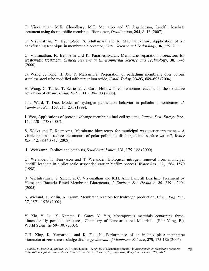
Gallucci, F., Basile, A. and Hai, F. I. "Introduction—A review of Membrane reactors" in Membranes for membrane reactors: Preparation, Optimization and Selection (eds. Basile, A., Gallucci, F.), page 1-62, Wiley InterScience, USA, 2011.
78
C. Visvanathan, M.K. Choudhary, M.T. Montalbo and V. Jegatheesan, Landfill leachate treatment using thermophilic membrane Bioreactor, Desalination, 204, 8–16 (2007). C. Visvanathan, Y. Byung-Soo, S. Muttamara and R. Maythanukhraw, Application of air backflushing technique in membrane bioreactor, Water Science and Technology, 36, 259–266. C. Visvanathan, R. Ben Aim and K. Parameshwaran, Membrane separation bioreactors for wastewater treatment, Critical Reviews in Environmental Science and Technology, 30, 1-48 (2000). D. Wang, J. Tong, H. Xu, Y. Matsamura, Preparation of palladium membrane over porous stainless steel tube modified with zirconium oxide, Catal. Today, 93–95, 689–693 (2004). H. Wang, C. Tablet, T. Schiestel, J. Caro, Hollow fiber membrane reactors for the oxidative activation of ethane, Catal. Today, 118, 98–103 (2006). T.L. Ward, T. Dao, Model of hydrogen permeation behavior in palladium membranes, J. Membrane Sci., 153, 211–231 (1999). J. Wee, Applications of proton exchange membrane fuel cell systems, Renew. Sust. Energy Rev., 11, 1720–1738 (2007). S. Weiss and T. Reemtsma, Membrane bioreactors for municipal wastewater treatment – A viable option to reduce the amount of polar pollutants discharged into surface waters?, Water Res., 42, 3837-3847 (2008). ,J. Weitkamp, Zeolites and catalysis, Solid State Ionics, 131, 175–188 (2000). U. Welander, T. Henrysson and T. Welander, Biological nitrogen removal from municipal landfill leachate in a pilot scale suspended carrier biofilm process, Water Res., 32, 1564–1570 (1998). B. Wichitsathian, S. Sindhuja, C. Visvanathan and K.H. Ahn, Landfill Leachate Treatment by Yeast and Bacteria Based Membrane Bioreactors, J. Environ. Sci. Health A, 39, 2391- 2404 (2005). S. Wieland, T. Melin, A. Lamm, Membrane reactors for hydrogen production, Chem. Eng. Sci., 57, 1571–1576 (2002). Y. Xia, Y. Lu, K. Kamata, B. Gates, Y. Yin, Macroporous materials containing three-dimensionally periodic structures, Chemistry of Nanostructured Materials (Ed.: Yang, P.), World Scientific 69–100 (2003). C.H. Xing, K. Yamamoto and K. Fukushi, Performance of an inclined-plate membrane bioreactor at zero excess sludge discharge, Journal of Membrane Science, 275, 175-186 (2006).

Gallucci, F., Basile, A. and Hai, F. I. "Introduction—A review of Membrane reactors" in Membranes for membrane reactors: Preparation, Optimization and Selection (eds. Basile, A., Gallucci, F.), page 1-62, Wiley InterScience, USA, 2011.
79
J. Xuan, M.K.H. Leung, D.Y.C. Leung, M. Ni, A review of biomass-derived fuel processors for fuel cell systems, Renew. Sust. Energy Rev., 13, 1301–1313 (2009). K. Yamamoto, H. Hiasa, M. Talat and T. Matsuo, Direct solid liquid separation using hollow fiber membranes in activated sludge aeration tank. Water Science and Technology, 21, 43–54 (1989). K. Yamamoto, Submerged MBR technology: An unfinished international adventure of 20 years. In: Lesjean B and Leiknes T (eds.) Final MBR-Network Workshop, pp.83-84. Berlin, Germany, March 31-April 1, 2009. A.A. Yaremchenko, V.V. Kharton, A.A. Valente, F.M.M. Snijkers, J.F.C. Cooymans, J.J. Luyten, F.M.B. Marques, Performance of tubular SrFe(Al)O3−ı–SrAl2O4 composite membranes in CO2- and CH4-containing atmospheres, J. Membrane Sci., 319, 141–148 (2008). K.M. Yeon, J.S. Park, C.H. Lee and S.M. Kim, Membrane coupled high performance compact reactor: a new MBR system for advanced wastewater treatment, Water Research, 39, 954–1961 (2005). X. Yin, L. Hong, Z. Liu, Integrating air separation with partial oxidation of methane-A novel configuration of asymmetric tubular ceramic membrane reactor, J. Membrane Sci., 311, 89–97 (2008). M.A. Yun, K.M. Yeon, J.S. Park, C.H. Lee, J. Chun, and D.J. Lim, Characterization of biofilm structure and its effect on membrane permeability in MBR for dye wastewater treatment, Water Res., 40, 45-52 (2006). J. Zaman, A. Chakma, Inorganic membrane reactors, J. Membrane Sci., 92, 1–28 (1994). C. Zhang, Z. Hong, X. Gu, Z. Zhong, W. Jin, N. Xu, Silicalite-1 zeolite membrane reactor packed with HZSM-5 catalyst for meta-xylene isomerization, Ind. Eng. Chem. Res., 48, 4293-4299 (2009). Y. Zhang, J. Gwak, Y. Murakoshi, T. Ikeara, R. Maeda, C. Nishimura, Hydrogen permeation characteristics of thin Pd membrane prepared by microfabrication technology, J. Membrane Sci., 277, 203–209 (2006). J.M. Zheng, J.M. Sousa, D. Mendes, L.M. Madeira, A. Mendes, Theoretical analysis of conversion enhancement in isothermal polymeric catalytic membrane reactors, Catal. Today, 118, 228–236 (2006).
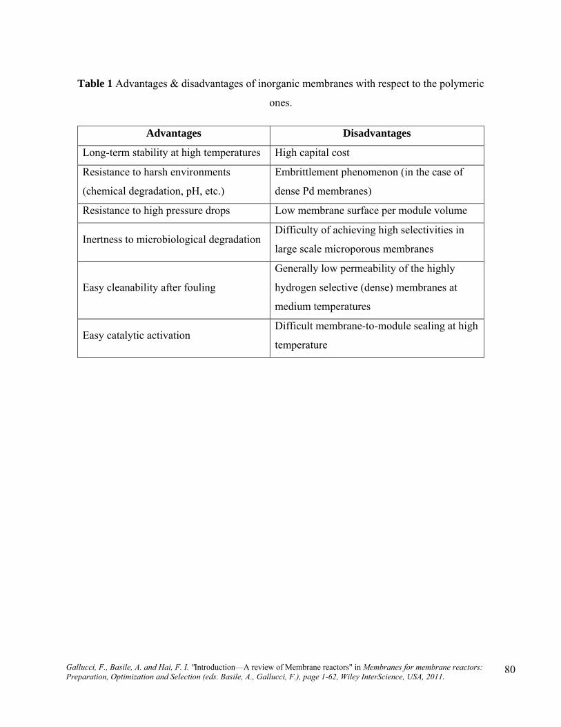
Gallucci, F., Basile, A. and Hai, F. I. "Introduction—A review of Membrane reactors" in Membranes for membrane reactors: Preparation, Optimization and Selection (eds. Basile, A., Gallucci, F.), page 1-62, Wiley InterScience, USA, 2011.
80
Table 1 Advantages & disadvantages of inorganic membranes with respect to the polymeric
ones.
Advantages Disadvantages
Long-term stability at high temperatures High capital cost
Resistance to harsh environments
(chemical degradation, pH, etc.)
Embrittlement phenomenon (in the case of
dense Pd membranes)
Resistance to high pressure drops Low membrane surface per module volume
Inertness to microbiological degradation Difficulty of achieving high selectivities in
large scale microporous membranes
Easy cleanability after fouling
Generally low permeability of the highly
hydrogen selective (dense) membranes at
medium temperatures
Easy catalytic activation Difficult membrane-to-module sealing at high
temperature
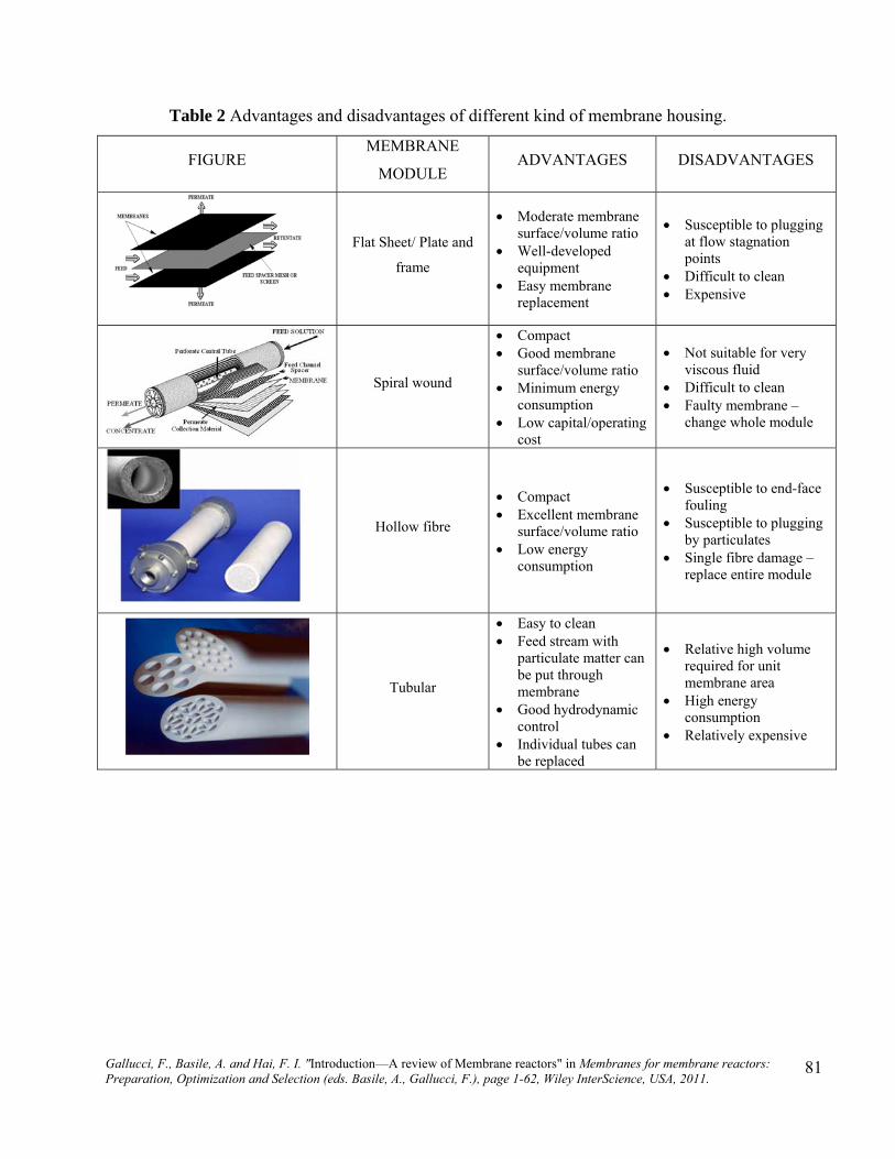
Gallucci, F., Basile, A. and Hai, F. I. "Introduction—A review of Membrane reactors" in Membranes for membrane reactors: Preparation, Optimization and Selection (eds. Basile, A., Gallucci, F.), page 1-62, Wiley InterScience, USA, 2011.
81
Table 2 Advantages and disadvantages of different kind of membrane housing.
FIGURE MEMBRANE
MODULE ADVANTAGES DISADVANTAGES
Flat Sheet/ Plate and
frame
Moderate membrane surface/volume ratio
Well-developed equipment
Easy membrane replacement
Susceptible to plugging at flow stagnation points
Difficult to clean Expensive
Spiral wound
Compact Good membrane
surface/volume ratio Minimum energy
consumption Low capital/operating
cost
Not suitable for very viscous fluid
Difficult to clean Faulty membrane –
change whole module
Hollow fibre
Compact Excellent membrane
surface/volume ratio Low energy
consumption
Susceptible to end-face fouling
Susceptible to plugging by particulates
Single fibre damage – replace entire module
Tubular
Easy to clean Feed stream with
particulate matter can be put through membrane
Good hydrodynamic control
Individual tubes can be replaced
Relative high volume required for unit membrane area
High energy consumption
Relatively expensive
Gallucci, F., Basile, A. and Hai, F. I. "Introduction—A review of Membrane reactors" in Membranes for membrane reactors: Preparation, Optimization and Selection (eds. Basile, A., Gallucci, F.), page 1-62, Wiley InterScience, USA, 2011.
82
Table 3 The operative conditions and the performances of MRs used to carry out the steam reforming reaction of biosources.
Bioethanol steam reforming Authors, reference Membrane Catalyst
Temperature [°C]
Pressure [bar]
Hydrogen recovery [%]
Conversion [%]
Gernot et al. (2006) Composite Pd-based BIOSTAR 600 100
Ethanol steam reforming Basile et al. (2006a,
2008b) and Gallucci et al. (2007b)
Dense Pd-Ag Ru-Al2O3 400 1.3 99
Methanol steam reforming
Wieland et al. (2002) Pd75Ag25 Pd60Cu40
Pd/V/Pd 300 25
96 78 -
Basile et al. (2005) Dense Pd-Ag Cu/ZnO/Al2O3 250 1.3 80
Basile et al. (2006b, 2007b)
MR1
MR2
MR3
Ru-Al2O3
350 600
350 550
350 450
1.3
30 100
45 65
87 100
Basile et al. (2008c) Dense Pd-Ag CuOAl2O3ZnOMgO 300 1.3 100
Damle (2009) Pd-Ag WGS catalyst
450
550
600
5.2
5.2 7.9
11.4
11.4
15
45 50 53
60
76
73 72 71
75
Bioglycerol steam reforming Iulianelli et al. (article
in press) Dense Pd-Ag Co/Al2O3 400 4.0 60 94
Dimethyl ether steam reforming Park et al. (2008) Composite membrane Cu/Al2O3
350 450
50
100
Acetic acid steam reforming
Basile et al. (2008d) Dense Pd-Ag (MR1)
Dense Pd-Ag (MR2)
Ni-Al2O3
Ni-Al2O3/ Ru-Al2O3
400 450
400 450
2.5
32 36
26 32
100 100
92 98
Iulianelli et al. (2008) Dense Pd-Ag Ni-Al2O3 400 4.0 70
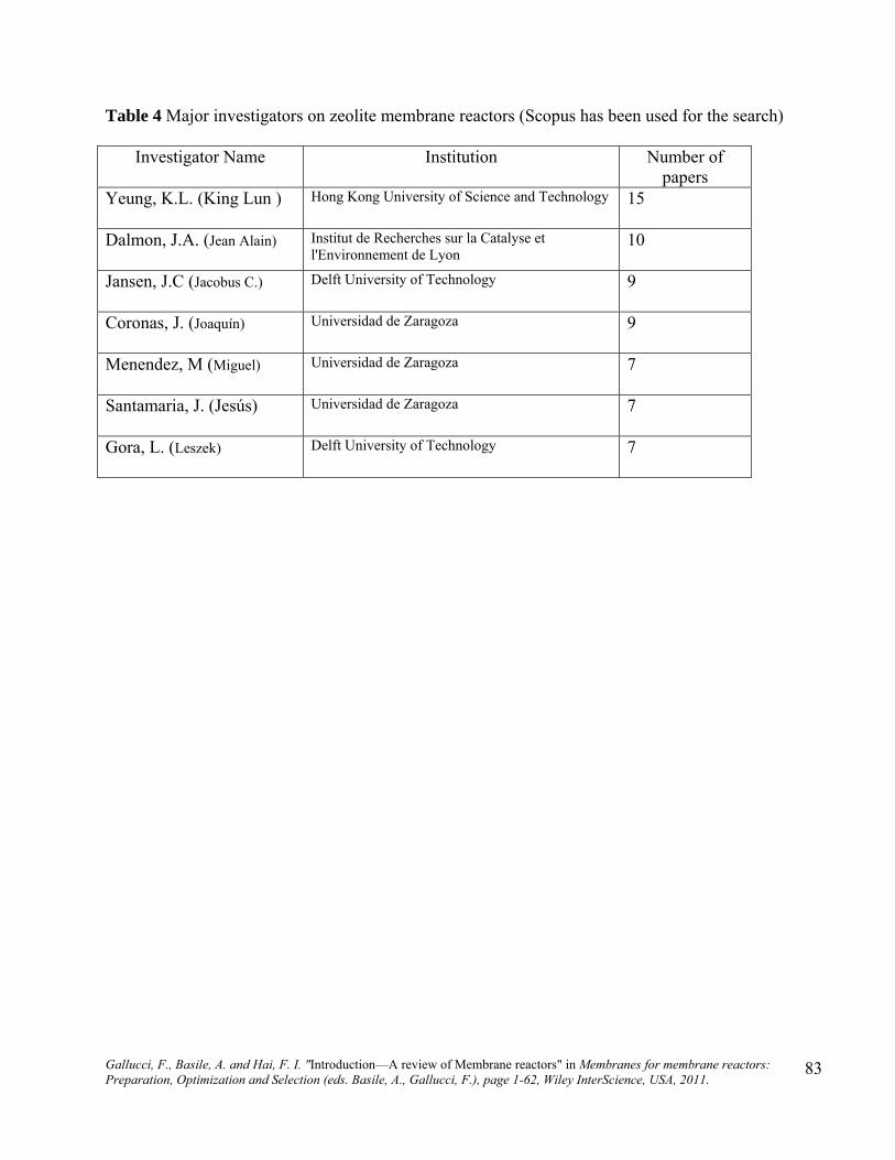
Gallucci, F., Basile, A. and Hai, F. I. "Introduction—A review of Membrane reactors" in Membranes for membrane reactors: Preparation, Optimization and Selection (eds. Basile, A., Gallucci, F.), page 1-62, Wiley InterScience, USA, 2011.
83
Table 4 Major investigators on zeolite membrane reactors (Scopus has been used for the search)
Investigator Name Institution Number of papers
Yeung, K.L. (King Lun ) Hong Kong University of Science and Technology 15
Dalmon, J.A. (Jean Alain) Institut de Recherches sur la Catalyse et l'Environnement de Lyon
10
Jansen, J.C (Jacobus C.) Delft University of Technology 9
Coronas, J. (Joaquín) Universidad de Zaragoza 9
Menendez, M (Miguel) Universidad de Zaragoza 7
Santamaria, J. (Jesús) Universidad de Zaragoza 7
Gora, L. (Leszek) Delft University of Technology 7

Gallucci, F., Basile, A. and Hai, F. I. "Introduction—A review of Membrane reactors" in Membranes for membrane reactors: Preparation, Optimization and Selection (eds. Basile, A., Gallucci, F.), page 1-62, Wiley InterScience, USA, 2011.
84
Table 5 Major investigators on fluidized bed membrane reactors (Scopus has been used for the
search)
Investigator Name Institution Number of papers
Elnashaie, S.S.E.H. (Said) Misr University for Science and Technology, Egypt
23
Grace, J.R. (John) The University of British Columbia, Canada 15
Kuipers, J.A.M. University of Twente, The Netherlands 12
Abashar, M.E.E. (Mohamed)
King Saud University, Saudi Arabia 6
Rahimpour, M.R. (Mohammad)
Shiraz University, Iran 5
Yan, Y. (Yibin) Auburn University, USA 5

Gallucci, F., Basile, A. and Hai, F. I. "Introduction—A review of Membrane reactors" in Membranes for membrane reactors: Preparation, Optimization and Selection (eds. Basile, A., Gallucci, F.), page 1-62, Wiley InterScience, USA, 2011.
85
Table 6 Major investigators on perovskite membrane reactors (Scopus has been used for the
search)
Investigator Name Institution Number of papers
Yang, W. (Weishen) Dalian Institute of Chemical Physics Chinese Academy of Sciences, China
18
Wang, H. (Hai) Ministry of Education China, School of Chemistry and Chemical Eng., China
18
Caro, J. (Jürgen) University of Hannover, Germany 14
Kharton, V.V. (Vladislav) Consejo Superior de Investigaciones Científicas, Spain
12
Yaremchenko, A.A. (Aleksey)
Centre for Research in Ceramics and Composite Materials, Portugal
10
Schiestel, T (Thomas) Fraunhofer-Institut für Grenzflächen und Bioverfahrenstechnik, Germany
9

Gallucci, F., Basile, A. and Hai, F. I. "Introduction—A review of Membrane reactors" in Membranes for membrane reactors: Preparation, Optimization and Selection (eds. Basile, A., Gallucci, F.), page 1-62, Wiley InterScience, USA, 2011.
86
Table 7 Major investigators on hollow fibre membrane reactors (Scopus has been used for the
search)
Investigator Name Institution Number of papers
Fane, A.G. (Anthony) Nanyang Technological University, Singapore 5
Tan, X. (Xiaoyao) Shandong University of Technology, China 4
Haginaka, J. (Jun) Mukogawa Women's University, Japan 4
Li, K. (Kang) Imperial College London, UK 4
Caro, J. (Jürgen) University of Hannover, Germany 4
Schiestel, T. (Thomas) Fraunhofer-Institut für Grenzflächen und Bioverfahrenstechnik, Germany
4

Gallucci, F., Basile, A. and Hai, F. I. "Introduction—A review of Membrane reactors" in Membranes for membrane reactors: Preparation, Optimization and Selection (eds. Basile, A., Gallucci, F.), page 1-62, Wiley InterScience, USA, 2011.
87
Table 8 Major investigators on photocatalytic membrane reactors (Scopus has been used for the search)
Investigator Name Institution Number of papers
Morawski, A.W. (Antoni) Polish Academy of Sciences, Poland 11
Palmisano, L. (Leonardo) University of Palermo, Italy
8
Molinari, R. (Raffaele) University of Calabria, Italy 8
Tomaszewska, M. (Maria) Polytechnic University Szczecin, Poland 5
Toyoda, M. (Masahiro) Kyoto University, Japan 5
Thiruvenkatachari, R. University of Technology Sydney, Australia 4

Gallucci, F., Basile, A. and Hai, F. I. "Introduction—A review of Membrane reactors" in Membranes for membrane reactors: Preparation, Optimization and Selection (eds. Basile, A., Gallucci, F.), page 1-62, Wiley InterScience, USA, 2011.
88
Figure 1 Poiseuille mechanism
Figure 2 Knudsen mechanism
Figure 3 Surface diffusion
Figure 4 Capillary condensation

Gallucci, F., Basile, A. and Hai, F. I. "Introduction—A review of Membrane reactors" in Membranes for membrane reactors: Preparation, Optimization and Selection (eds. Basile, A., Gallucci, F.), page 1-62, Wiley InterScience, USA, 2011.
89
Figure 5 Multi-layer diffusion
Figure 6 Molecular sieving

Gallucci, F., Basile, A. and Hai, F. I. "Introduction—A review of Membrane reactors" in Membranes for membrane reactors: Preparation, Optimization and Selection (eds. Basile, A., Gallucci, F.), page 1-62, Wiley InterScience, USA, 2011.
90
Figure 7 Hydrogen flux through palladium alloy membranes against metal content (Shu 1991).

Gallucci, F., Basile, A. and Hai, F. I. "Introduction—A review of Membrane reactors" in Membranes for membrane reactors: Preparation, Optimization and Selection (eds. Basile, A., Gallucci, F.), page 1-62, Wiley InterScience, USA, 2011.
91
0
50
100
150
200
250
300
1973
1975
1977
1979
1981
1983
1985
1987
1989
1991
1993
1995
1997
1999
2001
2003
2005
2007
2009
Time, year
Nu
mb
er o
f p
ub
lica
tio
n
July 2009
Figure 8 Number of publications vs time.

Gallucci, F., Basile, A. and Hai, F. I. "Introduction—A review of Membrane reactors" in Membranes for membrane reactors: Preparation, Optimization and Selection (eds. Basile, A., Gallucci, F.), page 1-62, Wiley InterScience, USA, 2011.
92
Figure 9 Flat membrane reactor :
i) removal of product for a limited reaction
thermodynamically;
ii) removal of favourite product;
iii) controlled addition of reactants.

Gallucci, F., Basile, A. and Hai, F. I. "Introduction—A review of Membrane reactors" in Membranes for membrane reactors: Preparation, Optimization and Selection (eds. Basile, A., Gallucci, F.), page 1-62, Wiley InterScience, USA, 2011.
93
Figure 10 Classification of MRs based on the function and position of membrane (McLeary
2006).

Gallucci, F., Basile, A. and Hai, F. I. "Introduction—A review of Membrane reactors" in Membranes for membrane reactors: Preparation, Optimization and Selection (eds. Basile, A., Gallucci, F.), page 1-62, Wiley InterScience, USA, 2011.
94
Figure 11 Two approaches in membrane reactors (Zaman 1994).
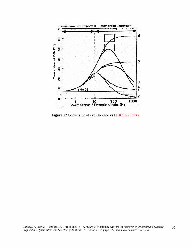
Gallucci, F., Basile, A. and Hai, F. I. "Introduction—A review of Membrane reactors" in Membranes for membrane reactors: Preparation, Optimization and Selection (eds. Basile, A., Gallucci, F.), page 1-62, Wiley InterScience, USA, 2011.
95
Figure 12 Conversion of cyclohexane vs H (Keizer 1994).

Gallucci, F., Basile, A. and Hai, F. I. "Introduction—A review of Membrane reactors" in Membranes for membrane reactors: Preparation, Optimization and Selection (eds. Basile, A., Gallucci, F.), page 1-62, Wiley InterScience, USA, 2011.
96
Figure 13 Energy sources used in the world provided by International Energy Agency
(http://www.eia.doe.gov/pub/international/iealf/tablee1p.xls).

Gallucci, F., Basile, A. and Hai, F. I. "Introduction—A review of Membrane reactors" in Membranes for membrane reactors: Preparation, Optimization and Selection (eds. Basile, A., Gallucci, F.), page 1-62, Wiley InterScience, USA, 2011.
97
Figure 14 Conceptual scheme of a dense Pd-Ag MR.

Gallucci, F., Basile, A. and Hai, F. I. "Introduction—A review of Membrane reactors" in Membranes for membrane reactors: Preparation, Optimization and Selection (eds. Basile, A., Gallucci, F.), page 1-62, Wiley InterScience, USA, 2011.
98
Figure 15 Selected hydrogen production technologies from various biomass (Xuan 2009).

Gallucci, F., Basile, A. and Hai, F. I. "Introduction—A review of Membrane reactors" in Membranes for membrane reactors: Preparation, Optimization and Selection (eds. Basile, A., Gallucci, F.), page 1-62, Wiley InterScience, USA, 2011.
99
Figure 16 Schematic of the experimental setup to measure gas back-mixing in the membrane-assisted fluidized bed reactor by steady-state tracer experiments: (a) detailed side view of the reactor; (b) simplified flow-sheet. Reprinted from Deshmukh 2005a with permission of ACS.

Gallucci, F., Basile, A. and Hai, F. I. "Introduction—A review of Membrane reactors" in Membranes for membrane reactors: Preparation, Optimization and Selection (eds. Basile, A., Gallucci, F.), page 1-62, Wiley InterScience, USA, 2011.
100
Figure 17 Experimental setup for partial oxidation of methanol to formaldehyde in a fluidized bed membrane reactor. Reprinted from Deshmukh 2005b with permission of ACS
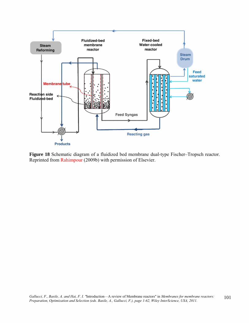
Gallucci, F., Basile, A. and Hai, F. I. "Introduction—A review of Membrane reactors" in Membranes for membrane reactors: Preparation, Optimization and Selection (eds. Basile, A., Gallucci, F.), page 1-62, Wiley InterScience, USA, 2011.
101
Figure 18 Schematic diagram of a fluidized bed membrane dual-type Fischer–Tropsch reactor. Reprinted from Rahimpour (2009b) with permission of Elsevier.
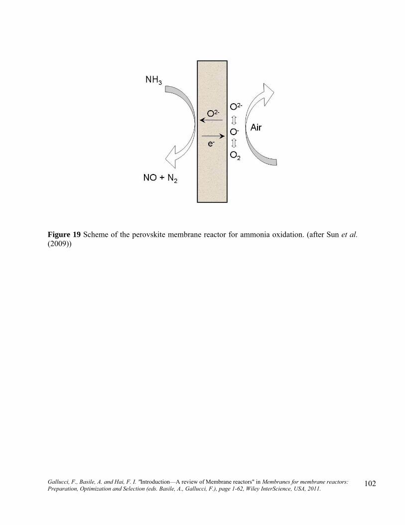
Gallucci, F., Basile, A. and Hai, F. I. "Introduction—A review of Membrane reactors" in Membranes for membrane reactors: Preparation, Optimization and Selection (eds. Basile, A., Gallucci, F.), page 1-62, Wiley InterScience, USA, 2011.
102
Figure 19 Scheme of the perovskite membrane reactor for ammonia oxidation. (after Sun et al. (2009))

Gallucci, F., Basile, A. and Hai, F. I. "Introduction—A review of Membrane reactors" in Membranes for membrane reactors: Preparation, Optimization and Selection (eds. Basile, A., Gallucci, F.), page 1-62, Wiley InterScience, USA, 2011.
103
Figure 20 Schematic diagram of a tube in tube hollow fiber membrane reactor for laboratory tests.
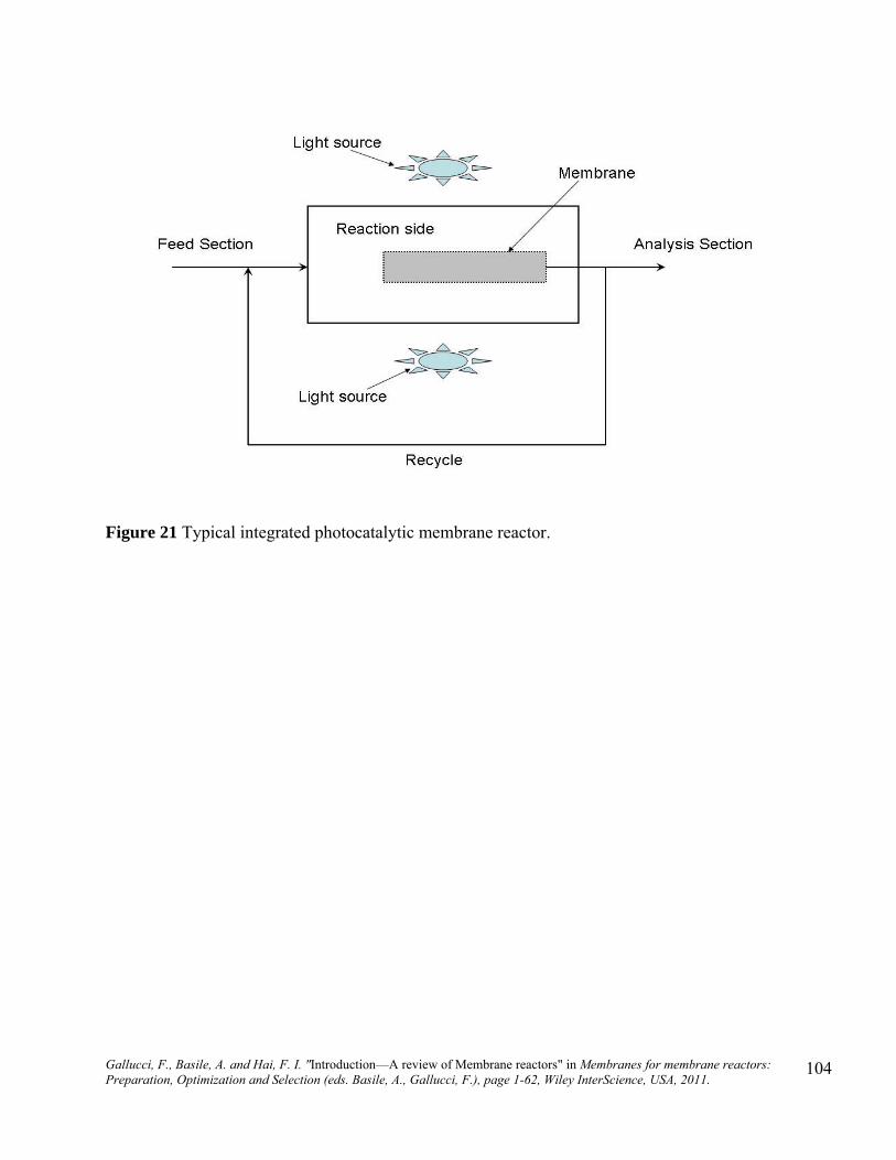
Gallucci, F., Basile, A. and Hai, F. I. "Introduction—A review of Membrane reactors" in Membranes for membrane reactors: Preparation, Optimization and Selection (eds. Basile, A., Gallucci, F.), page 1-62, Wiley InterScience, USA, 2011.
104
Figure 21 Typical integrated photocatalytic membrane reactor.
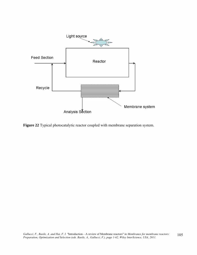
Gallucci, F., Basile, A. and Hai, F. I. "Introduction—A review of Membrane reactors" in Membranes for membrane reactors: Preparation, Optimization and Selection (eds. Basile, A., Gallucci, F.), page 1-62, Wiley InterScience, USA, 2011.
105
Figure 22 Typical photocatalytic reactor coupled with membrane separation system.

Gallucci, F., Basile, A. and Hai, F. I. "Introduction—A review of Membrane reactors" in Membranes for membrane reactors: Preparation, Optimization and Selection (eds. Basile, A., Gallucci, F.), page 1-62, Wiley InterScience, USA, 2011.
106
Membrane
Membrane permeate Wastewater
Bioreactor
Aeration
(a)
Wastewater
Membrane permeate
Aeration
Bioreactor
Air release
Return to bioreactor Permeate
d ti
Air injection
Feed supply Air lift
Permeate backwash
(b)
(c)
Figure 23: Simplified representation of MBR formats (a) Submerged MBR, (b) Sidestream MBR, (c) Airlift MBR

Gallucci, F., Basile, A. and Hai, F. I. "Introduction—A review of Membrane reactors" in Membranes for membrane reactors: Preparation, Optimization and Selection (eds. Basile, A., Gallucci, F.), page 1-62, Wiley InterScience, USA, 2011.
107
0
50
100
150
200
250
300
350
400
450
500
1990 1995 2000 2005 2010 2015
Global
EU
US-Canada
MB
R m
arke
t val
ue, m
illi
on $
Year
Figure 24: Estimated MBR market value (Dotted lines indicate projected values) Data source: Frost and Sullivan (2003, 2004, 2005); Hanft (2008)

Gallucci, F., Basile, A. and Hai, F. I. "Introduction—A review of Membrane reactors" in Membranes for membrane reactors: Preparation, Optimization and Selection (eds. Basile, A., Gallucci, F.), page 1-62, Wiley InterScience, USA, 2011.
108
Figure 25: Submerged membrane modules (a) Horizontally mounted single hollow fibers, (b) Hollow fiber bundles, (c) Flat sheet membrane module
(c)(a) (b)
Figure 26: Surface tension of common polymers for membrane Note: Polymer (1. Polytetrafluoroethylene, 2. Polyvinylidene Fluoride, 3. Polypropylene, 4. Poly Vinyl Chloride, 5. Polysulfone, 6. Polycarbonate, 7. Polyacrylonitrile, 8. Cellulose)
0
5
10
15
20
25
30
35
40
45
1 2 3 4 5 6 7 8Polymer
Sur
face
ten
sion
, dyn
es/c
m

Gallucci, F., Basile, A. and Hai, F. I. "Introduction—A review of Membrane reactors" in Membranes for membrane reactors: Preparation, Optimization and Selection (eds. Basile, A., Gallucci, F.), page 1-62, Wiley InterScience, USA, 2011.
109
Submerged
Sidestream Pumped
Airlift
Process configuration Membrane configuration
Hollow fiber
Flat sheet
Multi tube
(*Rare examples)
*
*
Figure 27: Features of commercial MBR technologies

Gallucci, F., Basile, A. and Hai, F. I. "Introduction—A review of Membrane reactors" in Membranes for membrane reactors: Preparation, Optimization and Selection (eds. Basile, A., Gallucci, F.), page 1-62, Wiley InterScience, USA, 2011.
110
(a) Horizontally mounted single hollow-fibers (Mitsubishi Rayon)
(b) Vertically mounted reinforced hollow-fibers (Zenon)
(c) One end free vertically mounted braid-supported hollow-fibers (Puron)
(d) Densely packed hollow-fiber bundles with unique aeration arrangement (Asahi kasei)
(e) Vertically mounted hollow-fiber bundles with unique two-phase jet cleaning arrangement (Memcor)
Legend: (1) sealed ends, (2) one end freely movable membrane filters, (3) central aeration, (4) filtrate removal, (5) backwashing
Legend: (1) fiber support, (2) module element, (3) air supply, (4) module row, (5) filtrate
Figure 28: Membrane system design principles

Gallucci, F., Basile, A. and Hai, F. I. "Introduction—A review of Membrane reactors" in Membranes for membrane reactors: Preparation, Optimization and Selection (eds. Basile, A., Gallucci, F.), page 1-62, Wiley InterScience, USA, 2011.
111
Figure 29: Comparative technical benefits of MBR over CAS
high quality effluent, ideal for post RO treatments (e.g. nanofiltration, ultrafiltration);
space savings enabling upgrading of plants without land expansion;
shorter start-up time;
low operating and maintenance manpower requirement (avg. 1.7 working hours per MLD);
automated control
Technical benefits
Figure 30: Technology bottlenecks
Research and development challenges -Membrane fouling -Effective pretreatment requirements -Membrane lifespan: -Cost -Plant capacity (scale up)
Problems often encountered by the operators
-membrane fouling during permeate backpulsing, -entrained air impacting suction pump operation, - bioreactor foaming, -inefficient aeration due to partial clogging of aerator holes, -no significant decrease of biosolid production, -scale build up on membrane and piping, -corrosion of concrete, hand rails and metallic components due to corrosive vapor produced during high temperature NaOCl cleaning, -membrane delamination and breakage during cleanings -odor from screening, compaction, drying beds and storage areas, -failure of control system.

Gallucci, F., Basile, A. and Hai, F. I. "Introduction—A review of Membrane reactors" in Membranes for membrane reactors: Preparation, Optimization and Selection (eds. Basile, A., Gallucci, F.), page 1-62, Wiley InterScience, USA, 2011.
112
Anaerobic Pretreatment
Methaneproduction
A small amount of high-strength organic waste(Kitchen waste disposer-wastewater & toilet flushing)
Biomass productionfrom liquid organic
waste
Aerobic MBR
Safeeffluent
A large amount of diluted organic wastewater (grey water)
(a very small amount of residue)
To cogeneration system
(*)
(*)N,P recovery option
Urine-separation is also worthwhile to be considered. (*)
•Renewable energy utilization•IT-based maintenance service system•User participation in monitoring
Figure 31: Next generation MBR system: anaerobic combination for on-site small scale advanced treatment (proposed by Yamamoto, 2009)