Embed Size (px)
Citation preview

INTRODUCING AN IMPROVEDPROCESS HAZARD ANALYSIS
METHOD—ENGAGE,MOTIVATE, AND CHALLENGE
YOUR TEAM
ByDave Ego & Rosalynn MacGregor,
Dego Management Services Ltd.,Kamloops, B.C., Canada

Page 1 of 12 Dego Paper
The intent of the Process Hazard Analysis (PHA) is to produce safer operating
facilities by identifying process hazards and eliminating or reducing the risk of a
hazardous event. The PHA is a legislative requirement in many jurisdictions for facilities
that handle or store hazardous materials. Several drawbacks to the “traditional” PHA
review approach are discussed in this article, and an improved method for conducting
these reviews is introduced.
The unique PHA method introduced here is not software specific, but is based on
a more visual, hands-on approach than most process safety professionals may have
previously encountered. Over twelve years of practice has lead to the development of the
efficient and effective techniques described here. The main features of this approach are:
• An accurate (field-checked) Process Hazard Drawing that contains all
technical information needed to conduct the PHA;
• A systematic approach to developing lists of analysis questions that are
created by following the flow on the Process Hazard Drawing;
• Active participation, promoted by the immediacy (in “operations language”)
of the analysis questions and the degree of visualization afforded by the
Process Hazard Drawing;
• The generation of a record of answers to the analysis questions and a
Recommendations Summary that stands the test of time and survives the
ravages of personnel changes.
• Follow-up documentation, in the form of a PHA manual and technical data
book, that is standardized, detailed, and easily understood. Revalidation and
Management of Change are easily captured by the PHA manual.

Page 2 of 12 Dego Paper
RECENT HISTORY AND EVOLUTION OF PROCESS HAZARDS ANALYSIS
In response to increased severity and cost of losses of containment from
hydrocarbon processing industry facilities, North American regulatory bodies and
industry embarked on initiatives to reduce the number and severity of incidents. Process
Safety Programs were developed and a list of Process Safety Elements evolved. The
industrial community developed standards and procedures for each Process Safety
element. Table 1 contains the main elements of the program:
Table 1: Process Safety Management Elements
Process Safety Management Policy Operating ProceduresProcess Hazard Analysis Pre-Startup Safety ReviewsProcess Safety Information Emergency ResponseRisk Assessment Operator TrainingMechanical Integrity Compliance AuditsManagement of Change Record Keeping/Document ControlIncident Investigation Contractor Safety Assessments
The Process Hazard Analysis is the heart of the program and leads to a more
logical approach in developing the other Process Safety elements. It is intended to be a
rigorous review of the process to determine all potential uncontrolled losses of
containment. In spite of the considerable efforts by the industry, preventable uncontrolled
losses of containment continue to occur, even in facilities that have completed PHA
reviews. Some of the many recent examples of uncontrolled losses include the release of
large quantities of aromatic extracts to surface water, tank failures caused by internal
explosions and the consequent release of toxic gases, and unburned flare gas releases
affecting the surrounding public. As well, newly constructed facilities have not been
immune to failure. At least one facility using leading edge process technology has been
Page 3 of 12 Dego Paper
constructed with identifiable process hazard deficiencies, even after being subjected to a
PHA review using commonly-used techniques and tools. Equipment modifications to
correct the deficiencies after start-up added to the final costs.
The consequences of PHA failures have had some deleterious effects on the
industry:
• Erosion of corporate credibility regarding protection of the public and
employees;
• Reduced profitability due to hefty fines, legal fees, lost production, and lost
productivity (as employees’ efforts are diverted from the pursuit of enhanced
business opportunities to addressing damage control, investigation, cleanup
repairs, etc.);
• Continuation of an already-established trend in the news media to turn public
opinion against industry;
• Erosion of confidence and credibility in the Process Safety Management
approach; and
• Frustration of Process Safety and Management personnel due to a perception
of improvements realized not being commensurate with the incurred costs.

Page 4 of 12 Dego Paper
FACTORS CONTRIBUTING TO PHA FAILURES
There are two typically-used approaches to PHA reviews:
• HAZOP: Hazard and Operability studies, in which specific points in a process
(“item” or “node”, often vessels, pumps, etc.) are focused on and an exhaustive
series of questions is asked with the goal of identifying all of the things that
could go wrong with the process at that point.
• “What-if” Analysis: Often used to analyze changes/additions to existing
facilities, the engineer (and possibly others, depending on the project scope)
asks himself all of the questions he can think of involving things that could go
wrong with the equipment. Depending on the experience of the engineer, the
review team make-up, team dynamics, etc., the number and nature of the
questions asked may vary, and the method tends to lack the necessary rigor to
fulfill the PHA objective.
The generally-accepted method worldwide for conducting rigorous PHA’s is
HAZOP (hazard and operability reviews). However, HAZOP reviews can be tedious for
participants, particularly process operators. The reviews can also be very lengthy, costing
companies significant man-hours. Worse, as stated above, process hazards have been
missed during reviews, most of which are obvious in hindsight and should have been
identified during the review meeting. Why were they missed?

Page 5 of 12 Dego Paper
Contributing factors in the failure to identify hazardous events are listed in Table 2.
Table 2: Why Commonly-used Process Hazards Analysis Techniques Fail
FAILURECATEGORY
FAILURE CONSEQUENCE
Poor ProblemDefinition
• Poor scope definition; failure todefine start points and end points,exclusions and inclusions.
• Failure to define process operatingconditions (pressures, temperatures,compositions) explicitly.
• Failure to define processthroughputs (maximum, normal,turndown) explicitly.
Participants confused; time wasted;hazards incorrectly identified or missed
Imperfect Tools P&IDs or MFDs (mechanical flowdiagrams) require flipping throughseveral drawings to determine theanswer to a given deviation.
Team distracted, time wasted
Inaccurate/out-of-date P&IDs (processand instrumentation diagrams) orMFD’s (mechanical flow diagrams)(drawings are often out-of-date, at leastto some degree, in jurisdictions notrequiring them to be current)
Frustration for the PHA session leaderand lost credibility with the Operationsand Engineering PHA team members
P&IDs or MFDs do not contain allinformation needed to evaluate acondition.
Time wasted, participants confused
Imperfect Approach The ‘item’ or ‘node’ approach detractsfrom understanding the process flow.
Missed Process Hazards
Shifting thinking logic by moving fromhazard identification to risk assessmentand then back again.
Team focus is diluted and teamdistracted from the identification ofhazards—process hazards missed.
OrganizationalChallenges
Downsizing and limited humanresources resistance of companies toestablish/maintain departments withleadership dedicated to Process SafetyManagement
Impaired in-house PHA expertise andability/drive to follow up on HAZOPrecommendations
Process Safety Managementresponsibilities added to existingorganizations
Conflicting priorities within thoseorganizations may cause Process Safetyinitiatives to “lose out”
Movement of personnel into and out ofPHA organizations (or the shifting ofPHA responsibilities within anorganization)
Impaired in-house PHA expertise andability/drive to follow up on PHAreview recommendations

Page 6 of 12 Dego Paper
CONSEQUENCES OF COMMONLY-USED PHA TECHNIQUES/TOOLS
There are three main areas that suffer negative consequences as a result of the
factors listed in Table 2: PHA review team dynamics, PHA review meeting progress, and
post-meeting documentation.
PHA Review Team Dynamics and Meeting Progress
Technical and Operations personnel often find the “item” or “node” approach to
be mind-numbing after a few hours (sometimes even sooner). These employees are
accustomed to dealing with real life issues in real time—valve failures, instrumentation
failures, power outages, etc—that occur in an operating facility. The “item” or “node”
approach is usually too far removed from their normal view of the process and its
equipment, and many of the questions can seem to be redundant or pointless (too
abstract).
The “item” or “node” approach also tends to be time-consuming. Participants are
often more than willing to hurry the work, to “end the agony” and get back to their
regular jobs. Time constraints on the meeting can also cause the PHA review team to
rush their answers. Furthermore, the tedium discourages Operations and Engineering
personnel from participating in subsequent Process Hazards Analysis reviews. Less than
full PHA team participation and less than optimal product quality is the result—
sometimes resulting in missed process hazards and/or deficiencies.
It can be difficult for the team to gauge progress during a review. Generally, the
team is scheduled to meet for a set period of time, yet they may lack tools for easily
determining whether they are half done at the half-way mark on the schedule, for
instance. This adds a stressor to meeting dynamics.
Page 7 of 12 Dego Paper
PHA documentation
PHA documentation tends to consist of a massive collection of worksheets and a
summary of deficiencies (or one or more disks of analogous computer files). The detailed
PHA worksheets are time-consuming to revalidate. They are also frequently misplaced,
partly due to their sheer bulk, but also because operating facility personnel find them of
little use in day-to-day operations.
What PHA documentation often lacks is a final document that clearly describes
all of the hazards found in a PHA review, along with all of the protective features that
control those hazards. Complete knowledge of the facility’s existing process hazards and
the protection against failure is therefore not passed on to Operations and Engineering,
where it is most needed to prevent incidents.
THE KEY TO SUCCESS—THE PROCESS HAZARD DRAWING
The authors have found that the use of a specialized visual tool is the key to
overcoming the drawbacks suffered with commonly-used PHA tools and techniques. The
Process Hazard Drawing (or PH Drawing; excerpts from some of the authors’ file
drawings are shown in Figures 1 and 2) is a specialized line drawing of the entire subject
process unit. These drawings have allowed amazing efficiencies to be achieved, saving
time and money1, while simultaneously improving PHA review team participation. The
result: more effective hazard identification, team members who want to come back for
the next review, and recommendations that are implemented—in short, safer facilities.
With the PH Drawing, the problem definition is simpler: if it is on the drawing, it
is within the scope of the review. All necessary information is on the drawing, giving it a
1 Adams, B., “Managing hazardous chemicals at Weyerhaeuser Kamloops,” Pulp & Paper Canada, 2000,101(4):T95-97.

Page 8 of 12 Dego Paper
clean, uncluttered appearance and eliminating distractions. A kick-off meeting is used to
confirm the operating conditions that will apply for the review.
Preparation for the PHA review meeting is efficient and focused with the PH
Drawing, since equipment that is on the diagram is field checked and its critical
parameters verified and included (PSV set pressures, vessel design temperatures,
pressures, routing of lines, locations of all valves, pump/compressor maximum shutoff
pressures, etc.). Once the PH Drawing is created, a complete, structured set of analysis
questions are generated by following the process flow. The complete analysis is
systematically prepared prior to the holding the PHA review meeting. The drawing is
subdivided into color-coded sections of piping and equipment, the pertinent analysis
questions are assigned to these sections, and the sections are numbered for clarity. Each
section is sized so that the team can complete the section in about an hour.
ADVANTAGES OF THE NEW METHOD
PHA Technique Improvements
The authors feel that the “item” or “node” approach is an imperfect way to look at
a process facility, since it allows participants to examine parts of a facility in isolation
from each other. Instead, to the maximum extent possible, the process flow should be
followed, in context—the way Operations and Engineering personnel are accustomed to
thinking about their facilities. This is a critical success factor of the new approach. It
tends to engage, motivate, and challenge the PHA team members, leading to improved
attention to detail. Often, the technique engenders friendly competition between team
members to be the first to identify the process hazards associated with a specific failure—
it is fun.
Page 9 of 12 Dego Paper
The PHA technique used by the authors usually keeps operability issues separate
from process hazard concerns. Typically, a PHA review team is there to look for hazards.
While it is commendable to improve the operability of a facility, the PHA review meeting
may not the best forum to achieve this (unless operability concerns have deliberately
been included in the scope of work). The objective of removing the operability issues
from the PHA review is to reduce the time required to complete the PHA and to keep the
focus on hazards identification. A “parking lot” document is created to capture
operability issues that could improve operability.
It is also important that the PHA technique identifies all of the process hazards
first, and then goes back to do risk analysis on those hazards during the same session.
Different thought processes are used to identify hazards and to analyze risks; alternating
between them tends to be inefficient and is often confusing to team members. This can
harm the momentum of the review meeting, demotivating the participants.
PHA Meeting Time Duration
Optimizing the use of PHA meeting time keeps costs down, motivates
participants, and produces the best quality results. As for most meetings, the best way to
use every moment of the meeting constructively is to prepare well. Accurate information,
as detailed above, reduces “wobbles” (and therefore delays) at the PHA review meeting.
After introductions, the PHA review team begins at the first section of the PH
Drawing, pulling out the set of prepared analysis questions that applies to that section
(refer to Figures 1 and 2 and Tables 3 and 4 for examples). A copy of the P&ID’s (or
MFD’s) is usually available to the team to facilitate checking of a line size or a process
control scheme and, of course, team members are encouraged to generate additional

Page 10 of 12 Dego Paper
questions as the review proceeds. After completion of Section 1, Section 2 is begun, and
so forth until the last section is completed.
PHA Meeting Time Management
The techniques and tools used by the authors for PHA facilitate time management
during the review. By using the PH Drawing and the numbered analysis sections, the
team is easily able to gauge its progress toward a defined goal. The techniques/tools used
by the authors:
1) Allow for an accurate estimate of the time required to do the review;
2) Allow PHA team members to see their progress as the meeting proceeds
(% complete versus schedule); and
3) Allow the PHA team members to determine early in the review whether they
will finish ahead of or on schedule, or will need more time—and if so, why.
PHA Documentation
By referring to the PH Drawing throughout, the results of the PHA are
documented in a PHA Manual generated by the authors. The PHA manual:
• Clearly describes the entire subject process;
• Clearly describes all of its process hazards;
• Clearly describes all of the protective features that control or prevent the hazards;
• Summarizes process hazards that are not currently protected against—in a way
that promotes timely correction of deficiencies; and
• Is easily revalidated and updated.
The PH Drawing is a key part of the post-review meeting documentation and is
and integral part of the PHA Manual.

Page 11 of 12 Dego Paper
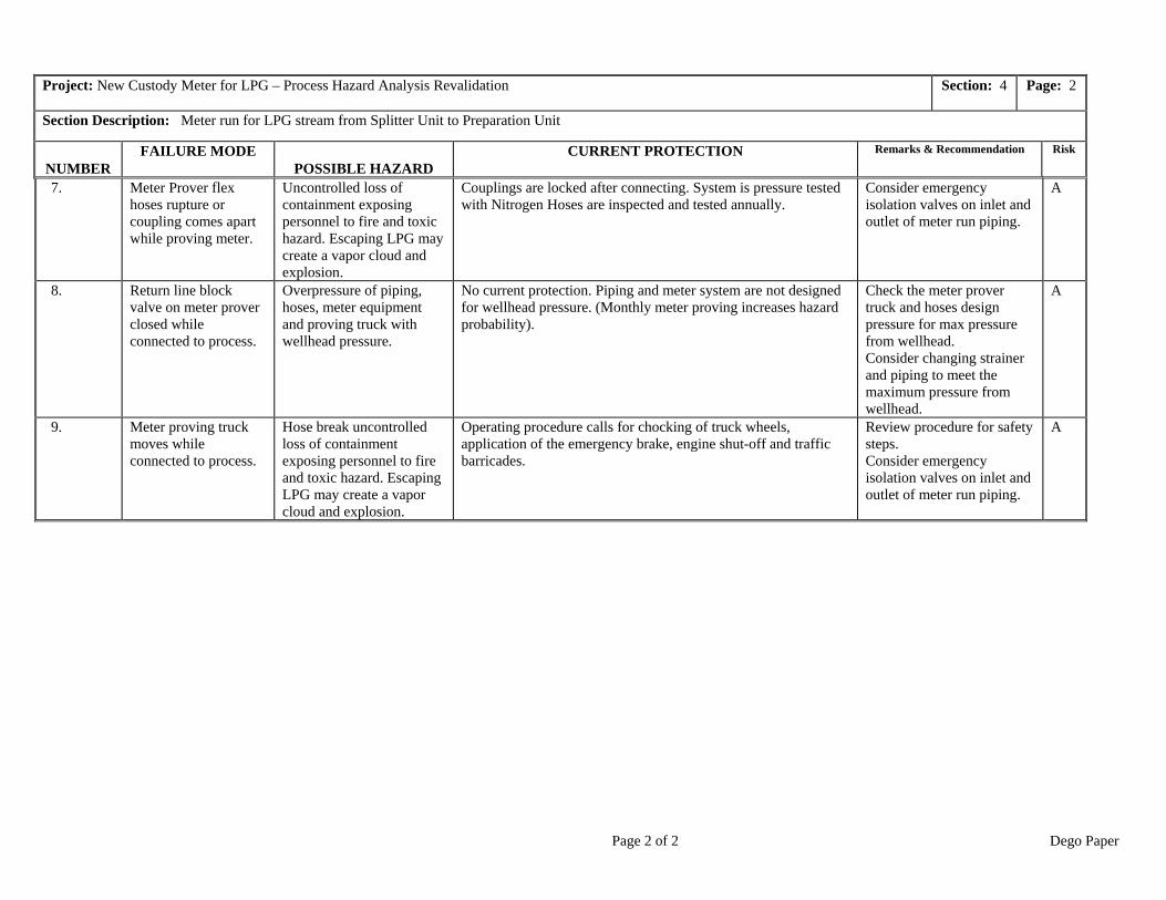
CASE STUDY 1: LPG FACILITY
LPG’s are stored in underground caverns at this facility and are processed in the
plant prior to being shipped to market (see Figure 1 and Table 3). The PHA method
introduced in this article was used in the early 1990’s on this plant; a revalidation of the
PHA was done, according to a master schedule, in the late 1990’s. During the intervening
years, a meter run was added (Section 4, in green, on Figure 1). The project included a
process hazard analysis of the change; however, that analysis was flawed and failed to
identify the significant overpressure concern identified on Table 3, item #’s 1, 3, and 8
(Risk level “A” represents the highest risk level for that facility). Fortunately, no
incidents occurred prior to the revalidation, although the owners of the facility incurred
significant cost to address the process hazard, once identified.
CASE STUDY 2: REFINERY (SHUTDOWN MODE)
While PHA reviews generally attempt to cover all reasonable operating modes, it
can be challenging to do the job well. The owners of this refinery (see Figure 2, Table 4)
were planning a major shutdown and wanted to ensure that no significant process hazards
were unidentified. Item #’s 7 and 8 identified the potential to overpressure the Extractor
if hydrogen supplies (shown on Section 3 of Figure 2) were incorrectly isolated and
emphasized the importance of this procedure to the owners. Item #9 identified the
potential for storage tank damage due to hydrogen breakthrough—to a tank located a
significant distance away from the subject process unit, and in another area of the
refinery. (The ease of identifying hazards to downstream units is one of the unique
strengths of the method presented in this article.) A recommendation to include vapor
detection in the rundown line was not implemented, as reliance on the existing procedure

Page 12 of 12 Dego Paper
was felt to be adequate for a “C” risk level. Unfortunately, the procedure was not
properly followed during a subsequent refinery shutdown and significant costs were
incurred by the owners to repair a sunken external floating roof; however, the owners
were aware of the potential for failure and had consciously chosen to accept the risk of its
occurrence.
CONCLUSION
The systematic approach to PHA described here has these advantages over
commonly-used PHA techniques and tools:
• It has been proven to identify more process hazards than any other method;
• It promotes and gains the buy-in of Operations and Engineering personnel (it is
relatively easy to get participants for PHA review teams when this approach is
used);
• It identifies all protective devices and procedures used to prevent/control all of the
process hazards and documents this information in a useful package for operating
facility personnel;
• It generates well-supported recommendations to address identified hazards;
• It facilitates “Management Of Change” by allowing the change to be quickly
located and evaluated on the PH drawing; and
• It provides documents that are easily updated and revalidated.
These advantages make this new PHA method efficient, cost-effective, and thorough in
identifying process hazards, toward fulfilling the goal of safer facilities.


4/24/2003

Page 1 of 2 Dego Paper
Project: New Custody Meter for LPG – Process Hazard Analysis Revalidation Section: 4 Page: 1
Section Description: Meter run for LPG stream from Splitter Unit to Preparation Unit
NUMBERFAILURE MODE
POSSIBLE HAZARDCURRENT PROTECTION Remarks & Recommendation Risk
1. Block valve in themeter line at the piperack is left closed aftera shutdown.
Overpressure piping withwellhead pressure leadingto line failure or gasketleaks. LPG leaks maycreate a vapor cloud andexplosion.
No current protection. Piping is not designed for wellheadpressure.
Consider locking valve openfor immediate short-termsolution.Long Term replace piping tomeet pressure rating.
A
2. Block valve on theinlet to StrainerSP-45 passes when thestrainer is open formaintenance?
Uncontrolled loss ofcontainment exposingpersonnel to fire and toxichazard.
Operating procedure calls for checking pressure before openingsystem to atmosphere.
Verify pressure gages are inplace in field.
B
3. SP-45 strainer plugs Overpressure upstreampiping and strainer withwellhead pressure.
PSV-08 is for thermalrelief and will not protectsystem for blocked flow.(PRV4080 set higher thanequip design press).
No current protection. Piping and strainer are not designed forwellhead pressure.
Consider changing strainerand piping to meet themaximum pressure fromwellhead.
A
4. Block valve on theoutlet of StrainerSP-45 is left closed?
Overpressure upstreampiping and strainer withwellhead pressure.
No current protection. Piping and strainer are not designed forwellhead pressure. (monthly meter proving increases hazardprobability).
Consider changing strainerand piping to meet themaximum pressure fromwellhead.
5. Strainer SP-45 is leftblocked in when not inuse.
Possible overpressure dueto thermal expansion.
PSV-08 provides thermal expansion protection (required due tolong length of piping)
6. Block valve to flareleft open after meterproving.
LPG will flow to the flare.Flare may plug due tohydrate formation. Pipingmay fracture due to coldtemperatures.
Unit Flare KO drum protects against liquid to flare. The Operatorwill detect Excessive flaring. Meter proving procedures reducethe risk.
Page 2 of 2 Dego Paper
Project: New Custody Meter for LPG – Process Hazard Analysis Revalidation Section: 4 Page: 2
Section Description: Meter run for LPG stream from Splitter Unit to Preparation Unit
NUMBERFAILURE MODE
POSSIBLE HAZARDCURRENT PROTECTION Remarks & Recommendation Risk
7. Meter Prover flexhoses rupture orcoupling comes apartwhile proving meter.
Uncontrolled loss ofcontainment exposingpersonnel to fire and toxichazard. Escaping LPG maycreate a vapor cloud andexplosion.
Couplings are locked after connecting. System is pressure testedwith Nitrogen Hoses are inspected and tested annually.
Consider emergencyisolation valves on inlet andoutlet of meter run piping.
A
8. Return line blockvalve on meter proverclosed whileconnected to process.
Overpressure of piping,hoses, meter equipmentand proving truck withwellhead pressure.
No current protection. Piping and meter system are not designedfor wellhead pressure. (Monthly meter proving increases hazardprobability).
Check the meter provertruck and hoses designpressure for max pressurefrom wellhead.Consider changing strainerand piping to meet themaximum pressure fromwellhead.
A
9. Meter proving truckmoves whileconnected to process.
Hose break uncontrolledloss of containmentexposing personnel to fireand toxic hazard. EscapingLPG may create a vaporcloud and explosion.
Operating procedure calls for chocking of truck wheels,application of the emergency brake, engine shut-off and trafficbarricades.
Review procedure for safetysteps.Consider emergencyisolation valves on inlet andoutlet of meter run piping.
A

Page 1 of 2 Dego Paper

Page 2 of 2 Dego Paper
4/24/2003

Page 2 of 2 Dego Paper
Project: Product Extract Unit Shutdown – Process Hazard Analysis Revalidation Section: 3 Page: 1
Section Description: Hydrogen Blanket and pressure control for Extractor Tower
NUMBER FAILURE EVENT POSSIBLE HAZARD CURRENT PROTECTION Remarks & Recommendation Risk
1. Hydrogen pressure islost during unitshutdown.
Back flow of Productliquids into hydrogensystem.
Procedures for shutting down the unit include isolating thehydrogen pressure control from the Extractor Tower and stoppingthe Product flow into the Tower. Level control continues tomaintain liquid level preventing liquid from rising to thehydrogen inlet. Hydrogen system is highly reliable.
2. Hydrogen pressureincreases during a unitshutdown.
Not a credible event.
3. Hydrogen temperatureincreases during a unitshutdown.
No hazard. Temperaturechanges limited to ambientconditions.
4. Hydrogen temperaturedecreases during a unitshutdown.
No hazard. Temperaturechanges limited to ambientconditions.
5. Hydrogen gas iscontaminated during aunit shutdown. (i.e.water, hydrocarbon,etc.)
No hazard is created forProduct Extractor.
6. Control valve PV-33Ain the hydrogenblanket gas to theExtractor Column failsclosed during a unitshutdown.
No hazard.
7. Control valve PV-33Ain the hydrogenblanket gas to theExtractor Column failsopen during a unitshutdown.
Overpressure Extractorcolumn.
Protected by RV-41. No credit is taken for shutdown proceduresthat include isolation the hydrogen system during the shutdown.
Verify relief load created byPV-33A failing open.
B

Page 2 of 2 Dego Paper
Project: Product Extract Unit Shutdown – Process Hazard Analysis Revalidation Section: 3 Page: 2
Section Description: H ydrogen Blanket and pressure control for Extractor Tower
NUM BER FAILUR E M O DE PO SSIBLE H A ZAR D CURRENT PRO TEC TIO N Remarks & Recommendation Risk
8. By pass around controlvalve PV -33A in thehydrogen blanket gasto the ExtractorColumn is left openduring a unitshutdown.
Overpressure Extractorcolumn.
Protected by RV-41. No credit is taken for shutdown proceduresthat include isolation the hydrogen system during the shutdown.
Verify relief load created byleaving bypass open aroundPV-33A.
B
9. Block valve in the lineto the top of theExtractor Column V -1is left open during ashutdown.
H ydrogen gas will flowthrough the ProductExtractor system to thestorage tank leading totipping and sinking of theexternal-floating roof. Lossof floating roof will allowvolatile vapors to escape toatmosphere creating avapor cloud and firehazard.
Shutdown procedures include isolating the unit at the batterylimit block valves and checking system pressure to ensure systemis depressured.
Consider vapor detection inthe rundown line to thestorage tank.
C
10. Control valve PV-33Bin the line to flarefrom the ExtractorColumn fails closedduring a unitshutdown.
No hazard.
11. Control valve PV-33Bin the line to flarefrom the ExtractorColumn fails openduring a unitshutdown.
Liquid to the flare leadingto potential for liquidhammer during a majorrelease, excessive flaring,reduced relief capacityduring a major event.
Procedures for shutting down the unit include isolating thehydrogen pressure control from the Extractor Tower and stoppingthe Product flow into the Tower. Level control continues tomaintain liquid level preventing liquid from rising to thehydrogen inlet.
12. By pass around controlvalve PV -33A in thehydrogen blanket gasto the ExtractorColumn is left openduring a unitshutdown.
Overpressure Extractorcolumn.
Protected by RV-41. No credit is taken for shutdown proceduresthat include isolation the hydrogen system during the shutdown.

Dego Paper
List of Tables and Figures
Table 1: PSM Elements
Table 2: Why Commonly-used Process Hazards Analysis Techniques Fail
Table 3: LPG Facility Analysis Section 4
Table 4: Refinery Shutdown Analysis Section 3 --missing from this rev.
Figure 1: Excerpt from a LPG Facility PH Drawing –-missing from this rev.
Figure 2: Excerpt from a Refinery PH Drawing --missing from this rev.

Dego Paper
Author bylines
Dave Ego holds a B. Sc. In Mechanical Engineering from the University of Alberta, 1974and has served with the Canadian Military Engineers until 1979. Dave spent several yearsat Dow Chemical facilities in Fort Saskatchewan before joining Endeco Engineering as amanager in 1983. As manager of a multi-discipline engineering team, Dave directed theday-to-day engineering activities at Syncrude Canada for a variety of projects. Daveformed Dego Management Services Inc. (www.dego.org) in 1986 specializing in ProcessSafety. Starting with the Guide Word HAZOP technique, Dego Management hasperformed many PHAs and used the experiences to develop the technique now in usetoday. Dave and his team continue to provide process safety services to a variety ofclients.
Rosalynn J. MacGregor holds a B.A.Sc. in Chemical Engineering from the University ofBritish Columbia and a M.Sc. in Chemical Engineering from the University of Alberta.She worked for Shell Canada for 15 years, 13 of them in operating locations in Alberta:Scotford Refinery near Edmonton, Peace River Complex (in-situ bitumen thermalextraction), and the Jumping Pound Gas Plant near Calgary. Rosalynn spent 2 years inthe Shell Canada head office process engineering group, but her clear preference is foroperating locations. Positions she held with Shell include process engineer, operationsengineer, and technical superintendent. Rosalynn joined Dego Management in 2001 asleader of their technical department (www.dego.org).