Embed Size (px)
Citation preview

Naval Construction Training Center Gulfport, MS 39501-5003 JUNE 2000
INTERSERVICE BUILDING APPRENTICE TRAINING
A-710-0010 (Navy) A-710-0032 (USAF) A-710-0033 (Army)
TRAINEE GUIDE
Phase “B”
PUBLISHED BY THE DIRECTION OF THE NAVAL EDUCATION AND TRAINING COMMAND

Naval Construction Training Centers
Gulfport, MS and Port Hueneme, CA
and Detachments at
Fort Leonard Wood, MO Sheppard AFB, TX
are accredited by the
Accrediting Commission of the Council on Occupational Education
41 Perimeter Center East, NE Suite 640 Atlanta, Georgia 30346
770-396-3898 800-917-2081
FAX 770-396-3790
TRAINEE GUIDE
FOR
INTERSERVICE BUILDING APPRENTICE TRAINING – Phase B
CIN: A-710-0010 (Navy) A-710-0032 (USAF) A-710-0033 (Army)
PREPARED BY
CENTER FOR SEABEES AND FACILITIES ENGINEERING NAVAL NAVAL SCHOOL, CIVIL ENGNINEER CORPS ORRICERS
3502 GOODSPEED ST. SUITE 1 PORT HUENEME, CA. 93043-4336
AUGUST 1995 (JUNE 2000)

TRAINING GUIDE __________________________________________________A-710-0010
2

TRAINING GUIDE __________________________________________________A-710-0010
3
CHANGE RECORD
Number and Description of Change Entered by Date
Numerous Grammatical Changes BUC(SCW) Maune
27 Mar 07

TRAINING GUIDE __________________________________________________A-710-0010
4

TRAINING GUIDE __________________________________________________A-710-0010
5
TABLE OF CONTENTS CHANGE RECORD......................................................................................................................3 TERMINAL OBJECTIVES .........................................................................................................7 COURSE MASTER SCHEDULE................................................................................................9 UNIT 5 – LIGHT FRAME CONSTRUCTION
Lesson Topic 5.1 Floor Framing...................................................................................5.1 page 1
Lesson Topic 5.2 Wall Framing....................................................................................5.2 page 1
Lesson Topic 5.3 Stair Construction ............................................................................5.3 page 1
Lesson Topic 10.1 Doors & Windows ........................................................................10.1 page 1
Lesson Topic 5.4 Roof Framing...................................................................................5.4 page 1
UNIT 6 – EXTERIOR CONSTRUCTION
Lesson Topic 6.1 Exterior Finish...................................................................................6.1 page 1
Lesson Topic 6.2 Composition Shingles ........................................................................6.2 page 1

TRAINING GUIDE __________________________________________________A-710-0010
6
TRAINING GUIDE __________________________________________________A-710-0010
7
TERMINAL OBJECTIVES 9.0 CONSTRUCT Floor framing in accordance with Builder 3&2 Vol. 2 NAVEDTRA
12521 and Carpentry, 3rd Edition, Delmar
10.0 CONSTRUCT wall framing in accordance Builder 3&2 Vol. 2 NAVEDTRA 12521 and Carpentry, 3rd Edition, Delmar.
11.0 CONSTRUCT stairs in accordance with Builder 3&2 Vol. 2 NAVEDTRA 12521 and Carpentry, 3rd Edition, Delmar.
12.0 PERFORM door and window installations in accordance with Builder 3&2 Vol. 2 NAVEDTRA 12521.
13.0 CONSTRUCT roof framing in accordance with Builder 3&2 Vol. 2 NAVEDTRA 12521 and Carpentry, 3rd Edition, Delmar.
14.0 INSTALL exterior clapboard siding in accordance with Builder 3&2 Vol. 2 NAVEDTRA 12521 and Carpentry, 3rd Edition, Delmar.
15.0 APPLY composition shingles in accordance with Builder 3&2 Vol. 2 NAVEDTRA 12521 and Carpentry, 3rd Edition, Delmar..

TRAINING GUIDE __________________________________________________A-710-0010
8
COURSE MASTER SCHEDULE
Topic No Type Topic RatioWeek 4 DAY 16 Test 1 Within Course Comprehensive Test #3 14:1 5.1 Class 2 Floor Framing 14:1 5.1 Class 3 Floor Framing 14:1 5.1 Class 4 Floor Framing 14:1 5.1 Lab 5 Floor Framing 14:1 5.1 Lab 6 Floor Framing 14:1 5.1 Lab 7 Floor Framing 14:1 5.1 Lab 8 Floor Framing 14:1 DAY 17 5.1 Lab 9 Floor Framing 14:1 5.1 Lab 10 Floor Framing 14:1 5.1 Lab 11 Floor Framing 14:1 5.1 Lab 12 Floor Framing 14:1 5.1 Lab 13 Floor Framing 14:1 5.1 Lab 14 Floor Framing 14:1 5.1 Lab 15 Floor Framing 14:1 5.1 Lab 16 Floor Framing 14:1 DAY 18 5.1 Lab 17 Floor Framing 14:1 5.1 Lab 18 Floor Framing 14:1 5.1 Lab 19 Floor Framing 14:1 5.1 Lab 20 Floor Framing 14:1 5.2 Class 21 Wall Framing 14:1 5.2 Class 22 Wall Framing 14:1 5.2 Class 23 Wall Framing 14:1 5.2 Class 24 Wall Framing 14:1 DAY 19 5.2 Lab 25 Wall Framing 14:1 5.2 Lab 26 Wall Framing 14:1 5.2 Lab 27 Wall Framing 14:1 5.2 Lab 28 Wall Framing 14:1 5.2 Lab 29 Wall Framing 14:1 5.2 Lab 30 Wall Framing 14:1 5.2 Lab 31 Wall Framing 14:1 5.2 Lab 32 Wall Framing 14:1 DAY 20 5.2 Lab 33 Wall Framing 14:1 5.2 Lab 34 Wall Framing 14:1 5.2 Lab 35 Wall Framing 14:1 5.2 Lab 36 Wall Framing 14:1 5.2 Lab 37 Wall Framing 14:1 5.2 Lab 38 Wall Framing 14:1 5.2 Lab 39 Wall Framing 14:1 5.2 Lab 40 Wall Framing 14:1 Week 5 DAY 21 5.2 Lab 41 Wall Framing 14:1 5.2 Lab 42 Wall Framing 14:1 5.2 Lab 43 Wall Framing 14:1 5.2 Lab 44 Wall Framing 14:1 5.2 Lab 45 Wall Framing 14:1 5.2 Lab 46 Wall Framing 14:1 5.2 Lab 47 Wall Framing 14:1

TRAINING GUIDE __________________________________________________A-710-0010
9
5.2 Lab 48 Wall Framing 14:1 Topic No Type Topic RatioDAY 22 5.2 Lab 49 Wall Framing 14:1 5.2 Lab 50 Wall Framing 14:1 5.2 Lab 51 Wall Framing 14:1 5.2 Lab 52 Wall Framing 14:1 5.2 Lab 53 Wall Framing 14:1 5.2 Lab 54 Wall Framing 14:1 5.2 Lab 55 Wall Framing 14:1 5.2 Lab 56 Wall Framing 14:1 DAY 23
5.2 Lab 57 Wall Framing 14:1 5.2 Lab 58 Wall Framing 14:1 5.2 Lab 59 Wall Framing 14:1 5.2 Lab 60 Wall Framing 14:1 5.3 Class 61 Stair Construction 14:1 5.3 Class 62 Stair Construction 14:1 5.3 Class 63 Stair Construction 14:1 5.3 Class 64 Stair Construction 14:1 DAY 24 5.3 Lab 65 Stair Construction 14:1 5.3 Lab 66 Stair Construction 14:1 5.3 Lab 67 Stair Construction 14:1 5.3 Lab 68 Stair Construction 14:1 5.3 Lab 69 Stair Construction 14:1 5.3 Lab 70 Stair Construction 14:1 5.3 Lab 71 Stair Construction 14:1 5.3 Lab 72 Stair Construction 14:1 DAY 25 5.3 Lab 73 Stair Construction 14:1 5.3 Lab 74 Stair Construction 14:1 5.3 Lab 75 Stair Construction 14:1 5.3 Lab 76 Stair Construction 14:1 Test 77 Within Course Comprehensive Test #4 14:1 10.1 Class 78 Doors and Windows 14:1 10.1 Class 79 Doors and Windows 14:1 10.1 Class 80 Doors and Windows 14:1 WEEK 6 DAY 26 10.1 Lab 81 Doors and Windows 14:1 10.1 Lab 82 Doors and Windows 14:1 10.1 Lab 83 Doors and Windows 14:1 10.1 Lab 84 Doors and Windows 14:1 10.1 Lab 85 Doors and Windows 14:1 10.1 Lab 86 Doors and Windows 14:1 10.1 Lab 87 Doors and Windows 14:1 10.1 Lab 88 Doors and Windows 14:1

TRAINING GUIDE __________________________________________________A-710-0010
10
Topic No Type Topic RatioDAY 27 10.1 Lab 89 Doors and Windows 14:1 6.1 Class 90 Exterior Finish 14:1 6.1 Class 91 Exterior Finish 14:1 6.1 Lab 92 Exterior Finish 14:1 6.1 Lab 93 Exterior Finish 14:1 6.1 Lab 94 Exterior Finish 14:1 6.1 Lab 95 Exterior Finish 14:1 6.1 Class 96 Exterior Finish 14:1 DAY 28 6.1 Lab 97 Exterior Finish 14:1 5.4 Class 98 Roof Framing 14:1 5.4 Class 99 Roof Framing 14:1 5.4 Class 100 Roof Framing 14:1 5.4 Class 101 Roof Framing 14:1 5.4 Class 102 Roof Framing 14:1 5.4 Class 103 Roof Framing 14:1 5.4 Class 104 Roof Framing 14:1 DAY 29 5.4 Lab 105 Roof Framing 14:1 5.4 Lab 106 Roof Framing 14:1 5.4 Lab 107 Roof Framing 14:1 5.4 Lab 108 Roof Framing 14:1 5.4 Lab 109 Roof Framing 14:1 5.4 Lab 110 Roof Framing 14:1 5.4 Lab 111 Roof Framing 14:1 5.4 Lab 112 Roof Framing 14:1 DAY 30 5.4 Lab 113 Roof Framing 14:1 5.4 Lab 114 Roof Framing 5.4 Lab 115 Roof Framing 14:1 5.4 Lab 116 Roof Framing 14:1 5.4 Lab 117 Roof Framing 5.4 Lab 118 Roof Framing 14:1 5.4 Lab 119 Roof Framing 14:1 5.4 Lab 120 Roof Framing 14:1 WEEK 7 DAY 31 5.4 Lab 121 Roof Framing 14:1 5.4 Lab 122 Roof Framing 14:1 5.4 Lab 123 Roof Framing 14:1 5.4 Lab 124 Roof Framing 14:1 6.2 Class 125 Composition Shingles 14:1 6.2 Class 126 Composition Shingles 14:1 6.2 Class 127 Composition Shingles 14:1 6.2 Class 128 Composition Shingles 14:1 DAY 32 6.2 Lab 129 Composition Shingles 14:1 6.2 Lab 130 Composition Shingles 14:1 6.2 Lab 131 Composition Shingles 14:1 6.2 Lab 132 Composition Shingles 14:1 6.2 Lab 133 Composition Shingles 14:1 6.2 Lab 134 Composition Shingles 14:1 6.2 Lab 135 Composition Shingles 6.2 Lab 136 Composition Shingles 14:1
TRAINING GUIDE __________________________________________________A-710-0010
11
DAY 33 6.2 Lab 137 Composition Shingles 14:1 6.2 Lab 138 Composition Shingles 14:1 6.2 Lab 139 Composition Shingles 14:1 6.2 Lab 140 Composition Shingles 14:1 6.2 Lab 141 Composition Shingles 14:1 Test 142 Within Course Comprehensive Test #5 14:1 11.1 Lab 143 Tear Down/Demolition 14:1 11.1 Lab 144 Tear Down/Demolition 14:1 DAY 34 11.1 Lab 145 Tear Down/Demolition 14:1 11.1 Lab 146 Tear Down/Demolition 14:1 11.1 Lab 147 Tear Down/Demolition 14:1 11.1 Lab 148 Tear Down/Demolition 14:1 11.1 Lab 149 Tear Down/Demolition 14:1 11.1 Lab 150 Tear Down/Demolition 14:1 11.1 Lab 151 Tear Down/Demolition 11.1 Lab 152 Tear Down/Demolition 14:1

TRAINEE GUIDE A-710-0010 LESSON TOPIC 5.1 FLOOR FRAMING
5.1 page 1
A. Introduction
During this lesson you will learn to construct the floor frame consisting of a box sill, girder, floor joist, solid bridging and sub-floor.
B. Enabling Objectives
9.1 IDENTIFY floor framing components, installation and repair/replacement procedures in accordance with Builder 3&2 Vol.2 NAVEDTRA 12521 and Carpentry 3rd Edition
9.2 CUT floor framing members to specified lengths in accordance with Builder 3&2 Vol.2 NAVEDTRA 12521 and Carpentry 3rd Edition
9.3 INSTALL sill plate per drawings and specifications in accordance with Builder 3&2 Vol.2 NAVEDTRA 12521 and Carpentry 3rd Edition
9.4 INSTALL floor and header joist in accordance with Builder 3&2 Vol.2 NAVEDTRA 12521 and Carpentry 3rd Edition
9.5 INSTALL solid bridging per drawings and specifications in accordance with Builder 3&2 Vol.2 NAVEDTRA 12521 and Carpentry 3rd Edition
9.6 INSTALL sub-flooring per drawings and specifications in accordance with Builder 3&2 Vol.2 NAVEDTRA 12521 and Carpentry 3rd Edition
9.7 OBSERVE all safety precautions during floor framing operations in accordance with applicable instructions
C. Topic Outline
1. Introduction
2. General Information about Light Framing
a. Major components
(1) Floor
(2) Wall
(3) Roof
(4) Stairs

TRAINEE GUIDE A-710-0010 LESSON TOPIC 5.1 FLOOR FRAMING
5.1 page 2
b. Platform/western -- modern method of construction and will be used in this course.
(1) The floor provides a work area upon which the builder can assemble and raise wall sections safely and accurately.
(2) Can be utilized in construction of single or multi-story structures
3. Floor construction (platform)
a. Box sill -- supports and holds the floor joists in place. This is the lowest member of the frame.
(1) Components
(a) Sill plate
1) Anchored to foundation walls
2) Supports joists and provides a fastening surface
3) Lowest framing member
(b) Header joist -- nailed edgewise on the outside of the sill plate
(2) Sill layout and placement
(a) Establish the building line points at each of the corners of the foundation, check for squareness of the structure
(b) Mark location of anchor bolts
1) Lay sills on top of foundation wall outside of anchor bolts
2) Square mark lines with combination square at the center of each anchor bolt
(c) Bore holes 1/4" larger than bolt diameter
(d) Install the sealer and/or termite shield if specified
(e) Position sills and install washers and nuts.
1) As sill plates are tightened, ensure proper alignment

TRAINEE GUIDE A-710-0010 LESSON TOPIC 5.1 FLOOR FRAMING
5.1 page 3
b. Girders
(1) Girders are large beams that support other beams or floor joists. They're generally used to support the ends of joists over a long span, thus taking the place of a supporting partition.
(2) Types
(a) Built-up or laminated -- generally made of three members fastened together, with the ends of girder resting in pockets formed into the foundation wall
(b) Solid -- heavy full-size timber that can be as large as 12" x 24", used where heavy loads are to be supported over long spans
(c) Steel
1) S beam, Standard
2) W beam, Wide flange
(3) Materials
TRAINEE GUIDE A-710-0010 LESSON TOPIC 5.1 FLOOR FRAMING
5.1 page 4
(a) Materials to be used will depend on the type of foundation used, the load to be carried and the span
(b) Materials should be straight and as free from knots as possible
(4) Installation
(a) The ends of a girder often rest in pockets prepared in concrete or masonry walls
1) Pockets should provide at least ½” clearance on each side and end of the girder to allow for air circulation and moisture evaporation.
2) Pockets should be deep enough to allow for shimming of the girder to the correct height.
3) Iron shims should be used and grouted (process of filling in the space around the shim and bottom of the pocket) in once the correct height is achieved. Wood shims should not be used.
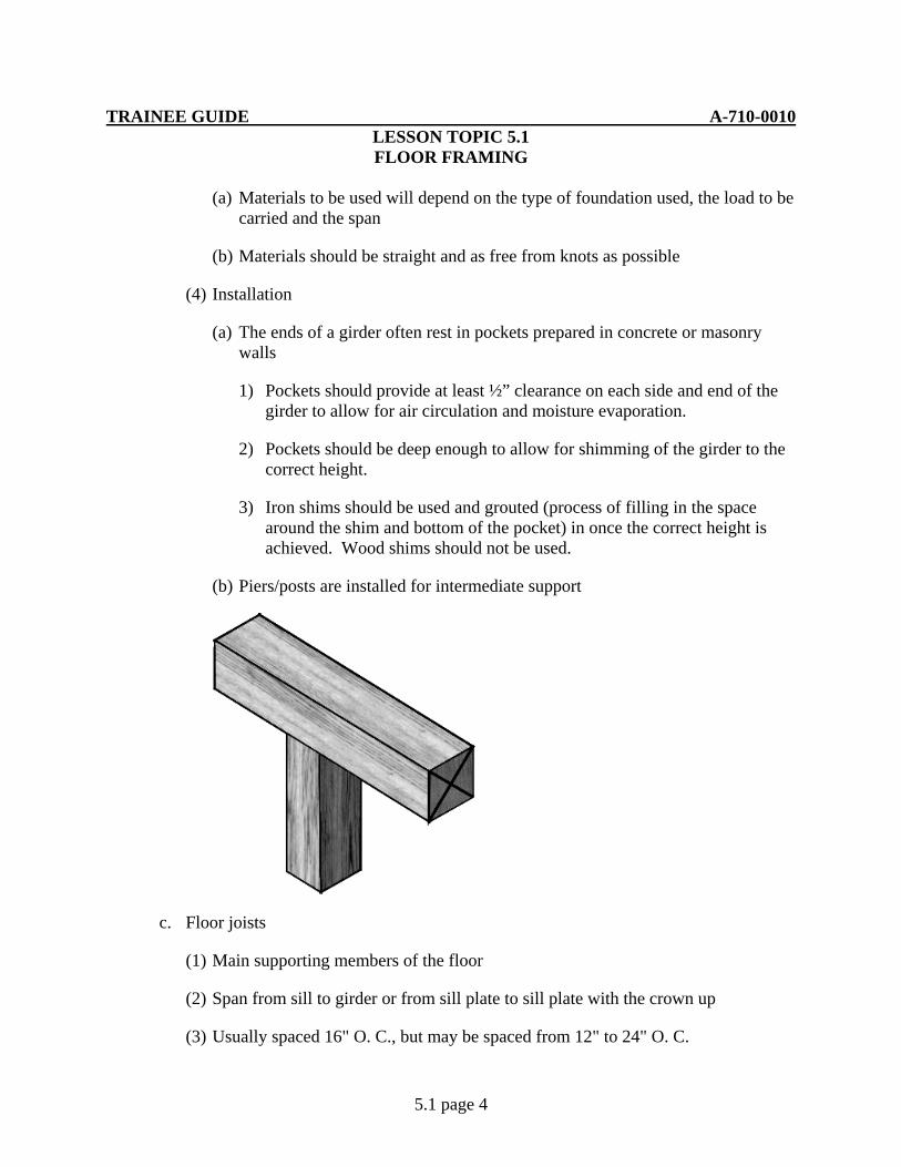
(b) Piers/posts are installed for intermediate support
c. Floor joists
(1) Main supporting members of the floor
(2) Span from sill to girder or from sill plate to sill plate with the crown up
(3) Usually spaced 16" O. C., but may be spaced from 12" to 24" O. C.
TRAINEE GUIDE A-710-0010 LESSON TOPIC 5.1 FLOOR FRAMING
5.1 page 5
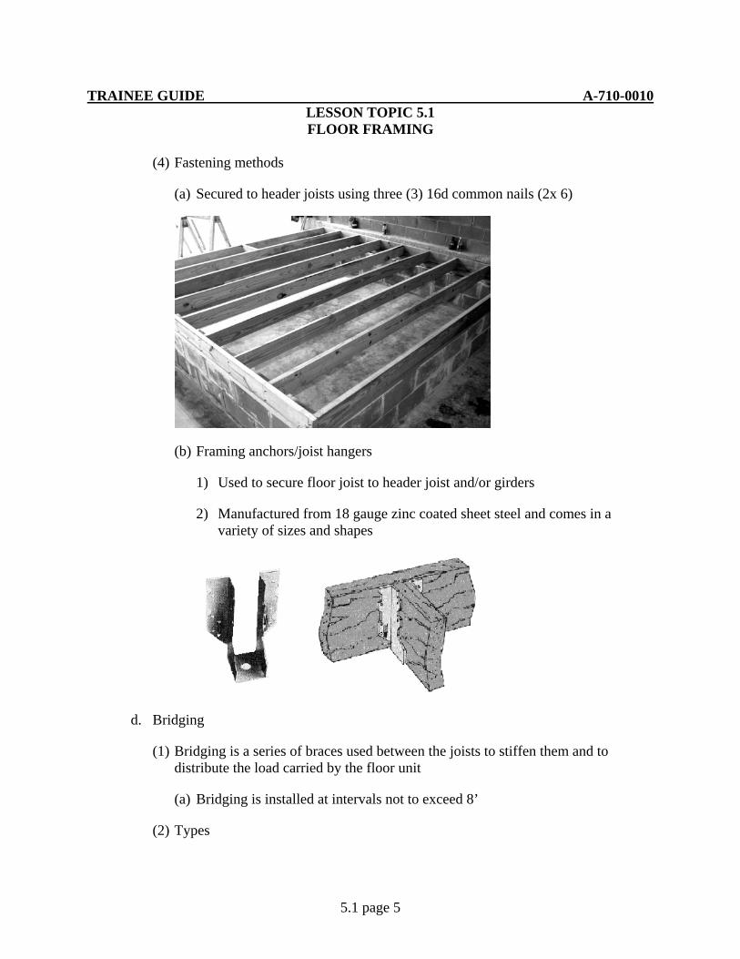
(4) Fastening methods
(a) Secured to header joists using three (3) 16d common nails (2x 6)
(b) Framing anchors/joist hangers
1) Used to secure floor joist to header joist and/or girders
2) Manufactured from 18 gauge zinc coated sheet steel and comes in a variety of sizes and shapes
d. Bridging
(1) Bridging is a series of braces used between the joists to stiffen them and to distribute the load carried by the floor unit
(a) Bridging is installed at intervals not to exceed 8’
(2) Types
TRAINEE GUIDE A-710-0010 LESSON TOPIC 5.1 FLOOR FRAMING
5.1 page 6
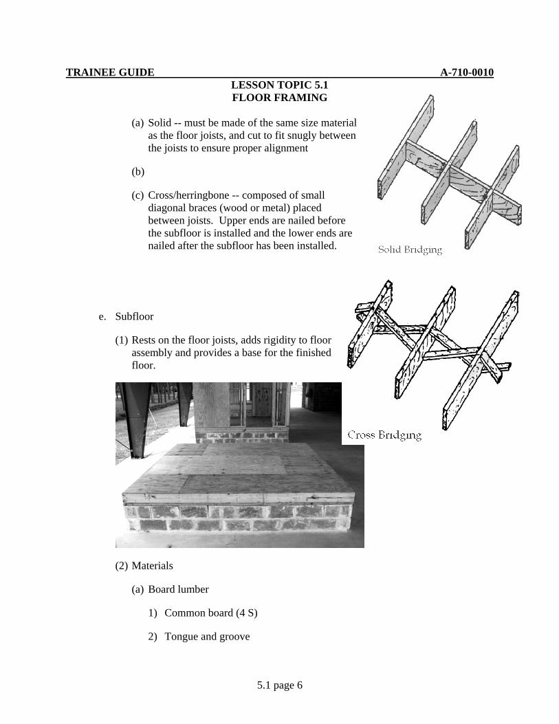
(a) Solid -- must be made of the same size material as the floor joists, and cut to fit snugly between the joists to ensure proper alignment
(b)
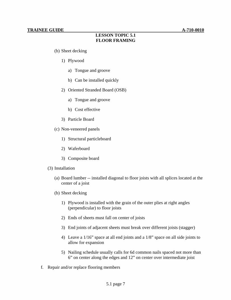
(c) Cross/herringbone -- composed of small diagonal braces (wood or metal) placed between joists. Upper ends are nailed before the subfloor is installed and the lower ends are nailed after the subfloor has been installed.
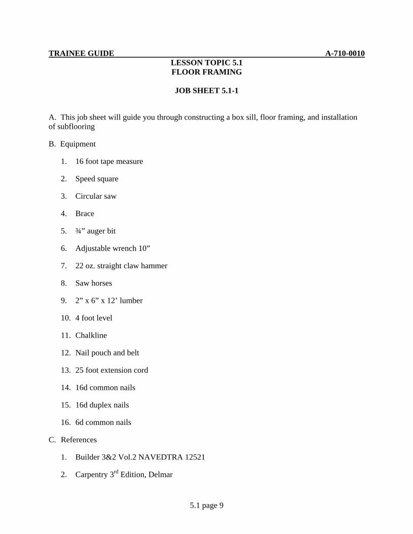
e. Subfloor
(1) Rests on the floor joists, adds rigidity to floor assembly and provides a base for the finished floor.
(2) Materials
(a) Board lumber
1) Common board (4 S)
2) Tongue and groove
TRAINEE GUIDE A-710-0010 LESSON TOPIC 5.1 FLOOR FRAMING
5.1 page 7
(b) Sheet decking
1) Plywood
a) Tongue and groove
b) Can be installed quickly
2) Oriented Stranded Board (OSB)
a) Tongue and groove
b) Cost effective
3) Particle Board
(c) Non-veneered panels
1) Structural particleboard
2) Waferboard
3) Composite board
(3) Installation
(a) Board lumber -- installed diagonal to floor joists with all splices located at the center of a joist
(b) Sheet decking
1) Plywood is installed with the grain of the outer plies at right angles (perpendicular) to floor joists
2) Ends of sheets must fall on center of joists
3) End joints of adjacent sheets must break over different joists (stagger)
4) Leave a 1/16” space at all end joints and a 1/8” space on all side joints to allow for expansion
5) Nailing schedule usually calls for 6d common nails spaced not more than 6” on center along the edges and 12” on center over intermediate joist
f. Repair and/or replace flooring members

TRAINEE GUIDE A-710-0010 LESSON TOPIC 5.1 FLOOR FRAMING
5.1 page 8
(1) Type of damage must first be determined prior to any repairs.
(a) Insect infestation such as termite or wood ants may require treatment prior to repairs.
(b) Structural damage may be caused either by nature or by man.
(2) Floor joist and decking repair
(a) When floor joists are cracked / broken, they can be jacked back into place leaving existing sheeting in place. Lumber of the same size can be installed next to the existing broken joist. This process is also known as scabbing.
(b) If the flooring member must be replaced due to excessive damage the following procedure is recommended. Remove existing sheeting to reveal joist. Remove joist, this may require additional support to other joist prior to removal, install new member of same size and fasten sheeting.
TRAINEE GUIDE A-710-0010 LESSON TOPIC 5.1 FLOOR FRAMING
5.1 page 9
JOB SHEET 5.1-1
A. This job sheet will guide you through constructing a box sill, floor framing, and installation of subflooring
B. Equipment
1. 16 foot tape measure
2. Speed square
3. Circular saw
4. Brace
5. ¾” auger bit
6. Adjustable wrench 10”
7. 22 oz. straight claw hammer
8. Saw horses
9. 2” x 6” x 12’ lumber
10. 4 foot level
11. Chalkline
12. Nail pouch and belt
13. 25 foot extension cord
14. 16d common nails
15. 16d duplex nails
16. 6d common nails
C. References
1. Builder 3&2 Vol.2 NAVEDTRA 12521
2. Carpentry 3rd Edition, Delmar

TRAINEE GUIDE A-710-0010 LESSON TOPIC 5.1 FLOOR FRAMING
5.1 page 10
D. Job steps
Note: While using this job sheet, refer to Foundation and Floor Framing Plan Sheet A-2 as necessary to complete assigned task
1. Determine lengths of required components
a. Sill Plate
(1) Long sill plate – length required____________ total number of pieces _______
(2) Short sill plate - length required____________ total number of pieces _______
b. Header joist - length required____________ total number of pieces _______
c. Floor Joist - length required____________ total number of pieces _______
d. Solid Bridging - length required____________ total number of pieces _______
Note: Bridging measurements will be verified by measuring distance between floor joists prior to cutting and installation
2. Sill plate location
a. Establish building corners and check to see if the building foundation is square
(1) If the building foundation walls are not square, measure in 5 ½” on both ends of one wall and snap a chalk line. This will establish a beginning reference line. From this point, you will have to measure in 5 ½” on a second wall and square up the new line with the reference line using the 3-4-5 method. Do this with the 2 remaining walls. Upon completion, your building lines will be square
3. Installation of sill plates
a. Select 2” x 6” lumber, check to see if one end of 2” x 6” is square prior to cutting to proper length
b. Layout of sill plates for bolt holes
(1) Lay 2” x 6” on top of foundation wall to the outside of the anchor bolts
(2) Using a speed square, mark centerlines of anchor bolts on board
TRAINEE GUIDE A-710-0010 LESSON TOPIC 5.1 FLOOR FRAMING
5.1 page 11
(3) Measure from the foundation wall or new established building line to the center of the bolt and transfer this measurement to the 2” x 6”. This will provide the location of the hole to be drilled for the anchor bolt
c. Bore holes for the anchor bolts using a brace and bit. The bit should be ¼” larger in diameter than the diameter of the anchor bolt
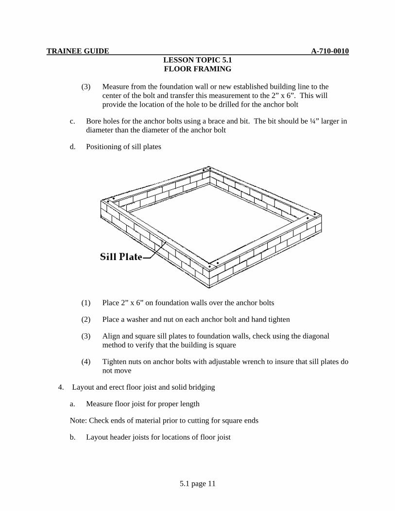
d. Positioning of sill plates
(1) Place 2” x 6” on foundation walls over the anchor bolts
(2) Place a washer and nut on each anchor bolt and hand tighten
(3) Align and square sill plates to foundation walls, check using the diagonal method to verify that the building is square
(4) Tighten nuts on anchor bolts with adjustable wrench to insure that sill plates do not move
4. Layout and erect floor joist and solid bridging
a. Measure floor joist for proper length
Note: Check ends of material prior to cutting for square ends
b. Layout header joists for locations of floor joist
TRAINEE GUIDE A-710-0010 LESSON TOPIC 5.1 FLOOR FRAMING
5.1 page 12
c. Place header and outside end joist on edge on the sill plates. Secure joist with 16d duplex nails to form the “box”. Ensure the box is square by checking using the diagonal or 3-4-5 method. Once the “box” is square, secure it to the sill plate using 16d duplex nails
Note: Duplex nails are used for training purposes only
d. Prepare and install floor joist
(1) Check all lumber for square ends prior to cutting to proper length
(2) With crown up, align and secure floor joist to layout (marked area) on header joist. Flush all floor joist to top edge of header joist
(3) Secure floor joist with two 16d duplex nails through header joist. Both ends of floor joist require securing
e. Preparation and installation of solid bridging
(1) Measure and record the measurements between each floor joist. All measurements will be taken from one header joist
Note: Do not take measurements for bridging from the center span of the floor joist
(2) Square the end of material prior to cutting bridging, cut to proper length
(3) Measure floor joist on opposite ends of floor to the center point. Snap a chalkline across the floor joist
(4) Align the solid bridging alternately to one side or the other of the chalkline
(5) Secure bridging with two 16d duplex nails on each end
5. Installation of subfloor
a. Lay the first sheet of plywood
Note: The wood grain of all sheets must be perpendicular to the floor joist
(1) Start the first sheet of plywood flush with the outside joist and header joist. If the building is square, the sheet will fit flush on the outside joist and header joist. The end of the sheet will fall on the center of the joist at the 8-foot layout mark. Secure sheet at 16” on center using 6d common nails. 16 inch on center is used for training purposes only. Normal nail pattern will be 8” on center
TRAINEE GUIDE A-710-0010 LESSON TOPIC 5.1 FLOOR FRAMING
5.1 page 13
b. Lay second sheet of plywood
(1) Measure distance from long grain end (8’ end) of first sheet to outside joist. Cut second sheet to proper dimensions. Install by butting cut piece of plywood to first sheet. Secure same as first sheet
c. Lay the remainder of the plywood sheets
(1) Repeat sheet laying process until entire joist assemble is covered. Remember to stager joints of plywood for additional strength
TRAINEE GUIDE A-710-0010 LESSON TOPIC 5.2 WALL FRAMING
5.2 page 1
A. Introduction
During this lesson you will learn to construct a wall frame, consisting of sole and top plates; common , trimmer and cripple studs; rough windowsills and headers; fire blocks and diagonal bracing.
B. Enabling Objectives
10.1 IDENTIFY floor framing components installation and repair/replacement procedures in accordance with Builder 3&2 Vol.2 NAVEDTRA 12521 and Carpentry 3rd Edition
10.2 CALCULATE the sizes of wall framing members to the nearest 1/16" in accordance with Builder 3&2 Vol.2 NAVEDTRA 12521 and Carpentry 3rd Edition
10.3 LAYOUT metal and wooden sole and top plates to within +/- 1/8" in accordance with Builder 3&2 Vol.2 NAVEDTRA 12521 and Carpentry 3rd Edition
10.4 CUT metal or wooden framing members to within +/- 1/8" in accordance with Builder 3&2 Vol.2 NAVEDTRA 12521 and Carpentry 3rd Edition
10.5 ASSEMBLE metal or wooden wall framing members flush to the inside in accordance with Builder 3&2 Vol.2 NAVEDTRA 12521 and Carpentry 3rd Edition
10.6 SECURE metal or wooden wall sections in proper location on the subfloor in accordance with Builder 3&2 Vol.2 NAVEDTRA 12521 and Carpentry 3rd Edition
10.7 INSTALL metal and wooden upper top plates ensuring it overlaps the corners of the lower top in accordance with Builder 3&2 Vol.2 NAVEDTRA 12521 and Carpentry 3rd Edition
10.8 OBSERVE all safety precautions during wall framing operations in accordance with applicable instructions
C. Topic Outline
1. Introduction
2. Platform Wall Components
a. Plates - horizontal members which tie the studs together at the top and bottom of the walls
(1) Types
TRAINEE GUIDE A-710-0010 LESSON TOPIC 5.2 WALL FRAMING
5.2 page 2
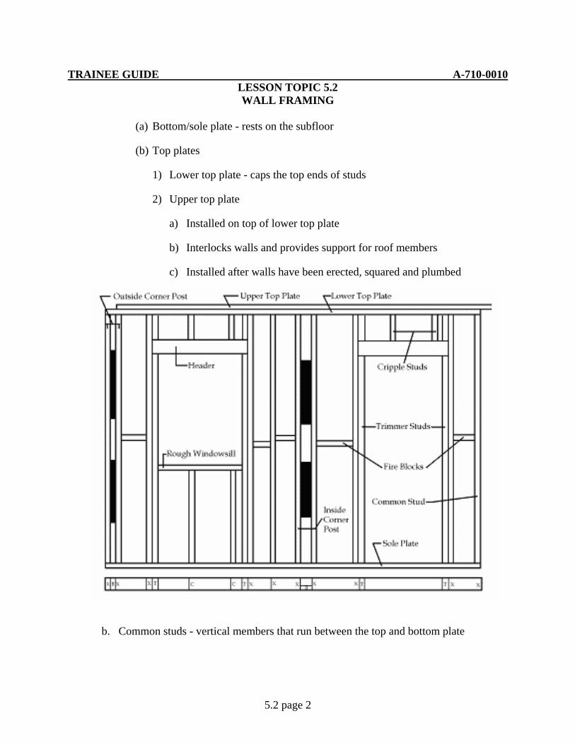
(a) Bottom/sole plate - rests on the subfloor
(b) Top plates
1) Lower top plate - caps the top ends of studs
2) Upper top plate
a) Installed on top of lower top plate
b) Interlocks walls and provides support for roof members
c) Installed after walls have been erected, squared and plumbed
b. Common studs - vertical members that run between the top and bottom plate
TRAINEE GUIDE A-710-0010 LESSON TOPIC 5.2 WALL FRAMING
5.2 page 3
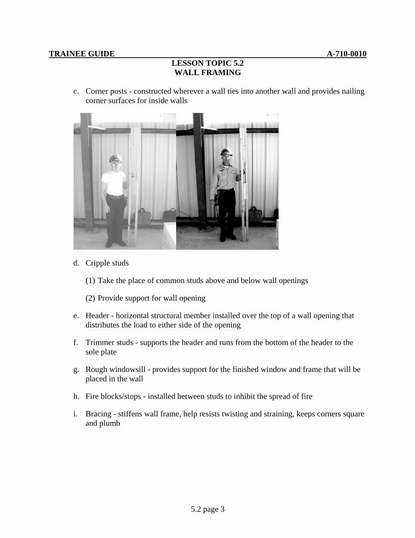
c. Corner posts - constructed wherever a wall ties into another wall and provides nailing corner surfaces for inside walls
d. Cripple studs
(1) Take the place of common studs above and below wall openings
(2) Provide support for wall opening
e. Header - horizontal structural member installed over the top of a wall opening that distributes the load to either side of the opening
f. Trimmer studs - supports the header and runs from the bottom of the header to the sole plate
g. Rough windowsill - provides support for the finished window and frame that will be placed in the wall
h. Fire blocks/stops - installed between studs to inhibit the spread of fire
i. Bracing - stiffens wall frame, help resists twisting and straining, keeps corners square and plumb
TRAINEE GUIDE A-710-0010 LESSON TOPIC 5.2 WALL FRAMING
5.2 page 4
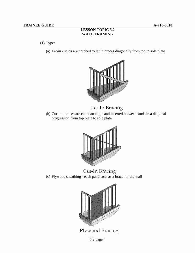
(1) Types
(a) Let-in - studs are notched to let in braces diagonally from top to sole plate
(b) Cut-in - braces are cut at an angle and inserted between studs in a diagonal progression from top plate to sole plate
(c) Plywood sheathing - each panel acts as a brace for the wall

TRAINEE GUIDE A-710-0010 LESSON TOPIC 5.2 WALL FRAMING
5.2 page 5
(d) Metal strap - a 2" wide strap made of 18 or 20 gauge galvanized steel, which is nailed directly to the studs diagonally from the top sole plate
3. Constructing a Wood-framed Wall
a. Sole and lower top plate layout - cut to the same length and laid out at the same time
(1) Square cut sole and lower top plate to size
(a) Measure the length of the subfloor
(2) Layout centerlines for all openings
(a) Refer to drawings, specifications, window and door schedules for centerline locations
(b) Square mark all centerlines
1) Mark window centerline with WCL
2) Mark door centerline with DCL
TRAINEE GUIDE A-710-0010 LESSON TOPIC 5.2 WALL FRAMING
5.2 page 6
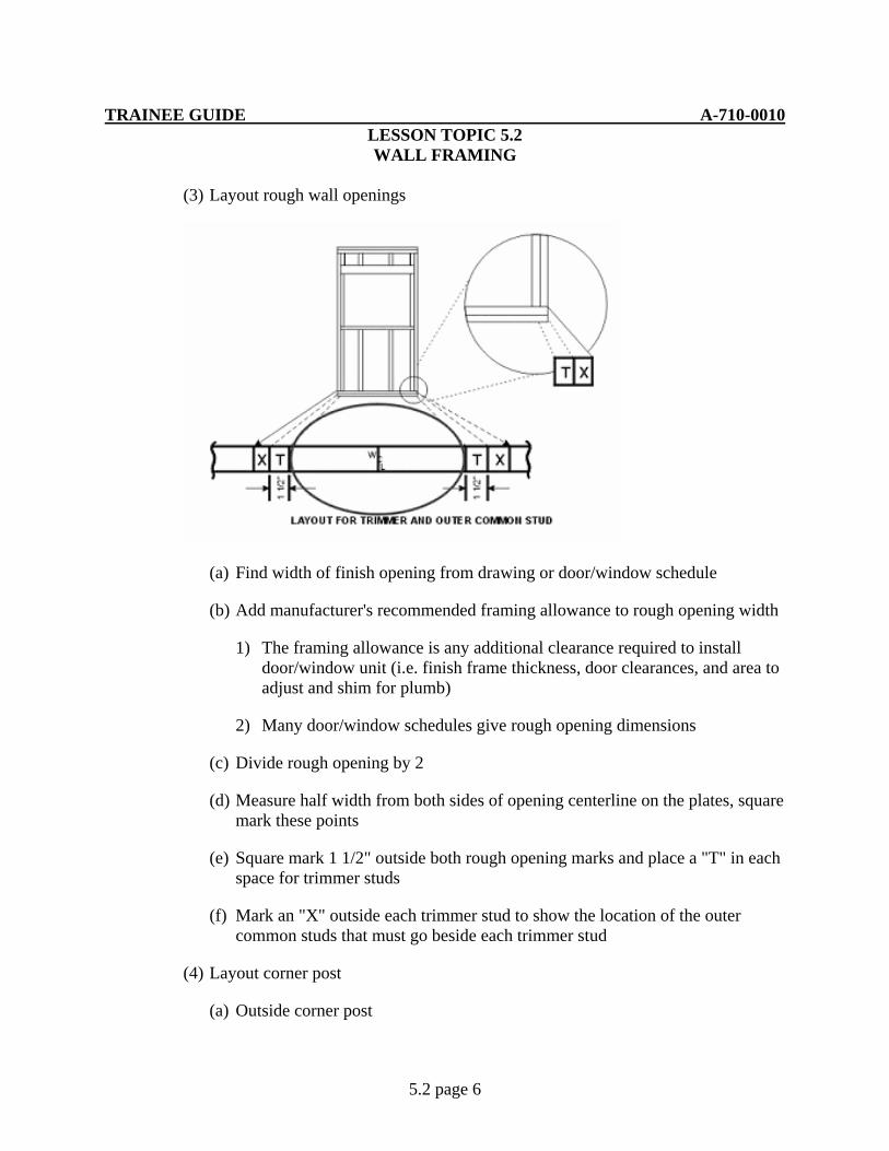
(3) Layout rough wall openings
(a) Find width of finish opening from drawing or door/window schedule
(b) Add manufacturer's recommended framing allowance to rough opening width
1) The framing allowance is any additional clearance required to install door/window unit (i.e. finish frame thickness, door clearances, and area to adjust and shim for plumb)
2) Many door/window schedules give rough opening dimensions
(c) Divide rough opening by 2
(d) Measure half width from both sides of opening centerline on the plates, square mark these points
(e) Square mark 1 1/2" outside both rough opening marks and place a "T" in each space for trimmer studs
(f) Mark an "X" outside each trimmer stud to show the location of the outer common studs that must go beside each trimmer stud
(4) Layout corner post
(a) Outside corner post

TRAINEE GUIDE A-710-0010 LESSON TOPIC 5.2 WALL FRAMING
5.2 page 7
1) Square mark 1 1/2" from outside corner of each plate and mark an "X" for common stud in this space
2) Square mark 3" from outside corner of each plate and mark a "B" for filler blocks in this space
3) Mark an "X" for common stud outside each filler block mark
(b) Inside corner posts (partition posts)
1) From outside corner, measure and mark distance to center line of the intersecting wall
2) From the centerline, measure in each direction one half the thickness of the intersecting wall
3) Square mark each of these points and place and X on each side of the line and draw a line
4) Mark a “B” for the filler blocks in the 1 ½” space
5) Mark a "B" for filler blocks in this space
(5) Layout stud pattern
(a) From outside corner, square mark 15 1/4", and mark an "X" for common stud on the side away from measuring corner
(b) From the 15 1/4" mark stretch tape to the end of plate and mark off every 16"
(c) Square mark these points and mark an "X" for common stud and a "C" for cripple stud (within all openings) on the side away from the measuring corner
TRAINEE GUIDE A-710-0010 LESSON TOPIC 5.2 WALL FRAMING
5.2 page 8
(d) Place an "X" for a common stud on the end of each plate
(6) Determine component lengths
(a) Common stud and corner post length
(b) Subtract the combined thickness of the double top plate and the sole plate (4 1/2") from the finished wall
(7) Header length
(a) Calculate by adding finished door/window width, framing allowance, and the thickness of both trimmers (3")
(8) Trimmer stud length
(a) Add manufacturer's recommended framing allowance to the finished door height
(b) Subtract thickness of sole plate (1 1/2")
Note: Door and window header heights are the same, therefore trimmer lengths will also be the same
(9) Rough window sill length
(a) Calculate by adding finished window width and framing allowance
(10) Cripple stud length
(a) After wall is assembled, measure the distance from the bottom of the lower top plate to the top of the header (door and window)
(b) After wall is assembled, measure the distance from the top of the sole plate to the bottom of rough window sill (window only)
b. Assemble wall frame - all major components should be cut before assembly begins
(1) Count the "X"s on the sole plate to determine the number of studs required, cut and lay aside
(2) Cut trimmer studs, rough windowsill, and header material (including scrap filler material) at predetermined lengths and lay aside
(3) Prepare the corner posts

TRAINEE GUIDE A-710-0010 LESSON TOPIC 5.2 WALL FRAMING
5.2 page 9
(a) Nail three 2" X 4" scrap, 12" to 30" long, at the top, middle and bottom, flush between two common studs
(4) Nail the corner post at the corner post marks on the plates
(5) Install all remaining studs for common studs next to the trimmer between the plates at each mark
(6) Prepare rough opening assemblies
(a) Door and window
1) Nail a trimmer stud flush to common stud
2) Align header material with spacer flush between them and nail together
3) Place the header on top of the trimmer studs and butted between the studs, nail in place
(b) Window only
1) Install rough window sill
a) Add the manufacturer's recommended framing allowance to finished window height for rough opening height
b) Measure down from header, the rough opening height and install rough window sill
(7) Nail pre-assembled rough opening unit to the sole and lower top plate
(8) Measure, cut, and install cripple studs above and below (window only) door and window rough openings
(9) Install fire block
(a) Most building codes require fire blocks in walls that are over 8’ 1” in height. If required, refer to specifications for exact placement of blocks
(b) Cut fire block to size, being sure to take measurements between the studs at the sole plate

TRAINEE GUIDE A-710-0010 LESSON TOPIC 5.2 WALL FRAMING
5.2 page 10
(c) Snap a chalk line along the wall at the height specified for the fire blocks. Nail the blocks alternately off set above and below the chalk line on the studs.
(10) Install plywood bracing
(a) On the exterior of the wall, flush the outer edge of the plywood with the outer edge of the corner post and the end flush with the lower top plate
(b) Nail in place once you have ensured wall is square
c. Erect and secure wall sections
(1) Plan sequence of raising wall sections
(a) Factors vary with situations
1) Sequence should ensure each raised section supports the next
2) Wall sections may have to be built and raised one at time because of lack of space
(2) Raise first wall section
(a) Use appropriate number of personnel to lift wall
(b) Align sole plate along edge of subfloor, raise section and nail sole plate
(c) Plumb and temporarily brace
(d) Raise remaining sections
1) Nail corners together as each section is raised and plumbed
(e) Install upper top plate
1) Nail on top of lower top plate, ensuring that the corners overlap

TRAINEE GUIDE A-710-0010 LESSON TOPIC 5.2 WALL FRAMING
5.2 page 11
(f) Remove temporary bracing
4. Metal Framing
a. Alternative to wood framing
(1) Can be framed entirely of metal, or combination of wood or metal
b. Framing members –cold-formed steel, electro-galvanized (to resist corrosion)
(1) Track/runner
(a) Used for top and bottom plate (normally there is not a second top plate)
TRAINEE GUIDE A-710-0010 LESSON TOPIC 5.2 WALL FRAMING
5.2 page 12
(b) Thickness range from 18 to 25 gauge, sized to match studs available in standard lengths of 10’
(2) Studs
(a) Thickness range from 18 to 25 gauge, width range from 1 5/8, 2 ½, 3 5/8, 4, and 6 inches with a leg thickness of either 1” or 1 ¼”. Lengths vary for 8’ to 16’ with custom sizes available up to 28’
(b) Notched at each end and knockouts located about 24 inches on center
1) Knockouts used to facilitate pipe and conduit installation
a) Size of knock out determines maximum size of pipe not stud size
(c) Advantage over wood is that metal does not shrink, swell, twist or warp. Termites cannot affect metal and metal will not dry rot, also with proper covering there can be a high fire rating.
(d) Chase (double stud) stud – used when large pipes, ducts, or other items must pass vertically or horizontally
1) Made by building two walls spaced closely together running parallel to each other
2) Spaces between the outside edges of the wall frames should not be more than 24” apart
3) Walls are tied together with either short pieces of steel or gypsum board
(3) Fasteners
(a) Pan head self tapping screw
(b) Sheet rock screws self tapping ¾” to 4 “
(4) Layout and assembly of wall
(a) Layout track for studs. Procedure is the same as for wood framing, except that care must be taken in the first measurement since metal studs are not as thick as wooden studs (1” or 1 1/4”)
(b) Cut studs to size. Aviation snips may be used on 25 gauge material; however, if thicker material is used or a lot of pieces must be cut, a chop saw with a metal cutting blade is preferred
TRAINEE GUIDE A-710-0010 LESSON TOPIC 5.2 WALL FRAMING
5.2 page 13
1) Care must be taken when cutting material. Sharp edges can cause serious injury.
(c) Studs can be fastened to the track with 3/8” self-drilling pan head screws or crimped together with a metal stud crimping tool
(d) Wall opening
1) Trimmer studs are not used in wall openings in metal framing. Fasten in place full length studs to the top and bottom tracks
2) Cut a length of track for use as a header. Track should be cut 6” longer than the width of the opening
3) Cut the flanges on each end 3” in from the ends and bend the ends at a 90 degree angle
4) Place the bent pieces over the studs at the desired height and fasten in place, cut and install cripple studs above header
5) Rough sills are made in the same manner for window openings
c. Repair and/or replace metal or wooden studs
(1) Type of damage must first be determined prior to any repairs
(a) Moisture and chemicals may decompose metal studs, commonly known as rust.
(b) Insect infestation such as termites or wood ants in wooden studs may require treatment prior to repairs.
(c) Natural or man-made forces may cause structural damage.
(2) Metal and wood stud repair
(a) Removal of interior or exterior covering is required to repair damaged studs. In extreme cases, both interior and exterior covering may have to be removed prior to repairs.
(b) Two types of repair
1) Once covering has been removed in the damaged area, the decision must be made to remove the entire stud or cut off damaged area. When removing a full stud the top plates will need to be supported until the new
TRAINEE GUIDE A-710-0010 LESSON TOPIC 5.2 WALL FRAMING
5.2 page 14
member or members can be installed. Once repaired members have been installed, remove bracing and install covering to match existing finish.
2) When removing only the damaged portion the stud the top plate should be supported until the studs is repaired. A piece of material the same size that was removed should be installed in the place of the removed section. A length of material longer than the replaced piece shall be fastened to the side of the stud. This is known as scabbing. Once repaired member has been installed, remove bracing and install covering to match original finish.
TRAINEE GUIDE A-710-0010 LESSON TOPIC 5.2 WALL FRAMING
5.2 page 15
JOB SHEET 5.2-1
A. This job sheet is to guide you through wall framing
B. Equipment list
1. 16’ measuring tape
2. Framing square
3. Speed square
4. Crosscut handsaw
5. Circular saw
6. Sawhorses
7. Chalk line
8. 2” x4” lumber
9. 16d common nails
10. 8d common nails
11. 22 oz framing hammer
12. Screw gun
13. Metal studs
14. Track for metal studs
15. Pan head screws
16. Drywall screws
17. Nail pouch and belt
18. Stepladder
19. Chopsaw with abrasive blade
20. Aviation snips
TRAINEE GUIDE A-710-0010 LESSON TOPIC 5.2 WALL FRAMING
5.2 page 16
C. References
1. Builder 3&2 Vol.2 NAVEDTRA 12521
2. Carpentry 3rd Edition, Delmar
D. Job steps
NOTE: For layout of walls, windows, and doors refer to floor plan. The instructor will give all other dimensions to you
1. Determine Component lengths
a. Wall height:___________
(1) Door size:_________
(2) Window size: _________
b. Stud spacing ___________on center
c. Framing allowance
(1) Window:
a) Width:_________
b) Height: ________
(2) Door
a) Width: ________
b) Height: ________
d. Sole plate/top plate length ___________
e. Common stud length ___________ each ________
f. Trimmers
(1) Window length __________ each________
(2) Door length __________each ________
TRAINEE GUIDE A-710-0010 LESSON TOPIC 5.2 WALL FRAMING
5.2 page 17
g. Headers/rough sill
h. Note: Window header will be at the same elevation as the door header
(1) Window Length ________ each _________
(2) Door length __________ each _________
i. Cripple studs
(1) Window length above header__________
(2) Window length below rough sill ________
(3) Door length above header _________
2. Layout sole and top plates
Note: To save time and to improve accuracy, layout the top plate and sole plate at the same time, this is done by laying them side-by-side. For training purposes only, the exterior walls will have one corner post
a. Select required material
b. Check to ensure that material has one square end prior to starting layout. If material does not have a squared end, square one end before proceeding
c. Layout plates
(1) Refer to floor plan for location of window and door opening center line (CL). Find overall length of wall
(2) Measure distance to WCL and/or DCL from the end of the plates. Using a square make a straight line and write the proper identification on the plates
(3) Add framing allowance to size of opening. The instructor has given dimensions to you
(4) Divide the rough opening width in half. Measuring from the centerline mark each half of the opening
d. Layout trimmer studs
(1) Using a square, place a line 1 1/2” to the outside of the rough opening width line for doors or windows. Mark with a “T” for trimmer on the inside of the line
TRAINEE GUIDE A-710-0010 LESSON TOPIC 5.2 WALL FRAMING
5.2 page 18
(2) Mark an X outside each trimmer stud to show the location of a full stud
e. Layout plates for outside corner post
(1) Measure in from outside corner of each plate 1 ½” and draw a line with a square than place an X for common stud before the line. At 3” place a line with a square than place a B for filler block between 1 ½” and 3” lines. On the outside of the 3” line, place an X for second common stud to complete the corner post
f. Inside corner posts/partition posts
(1) Refer to floor plan for centerline of interior wall
(2) From outside corner measure and mark centerline of wall on plates, divide width of stud (3 1/2”) in half. Measuring from centerline in each direction one half the width of a stud, place a line using a square. On the outside of the lines place a X for common studs and in the center place a B for filler block
(3) Layout for common studs and cripples
a) From the outside corner, measure in 15 ¼” and place a line using a square. Place an X on the side of the line away from the starting point. From the 15 ¼” line, measure over 16” and place a line using a square. Do this process for the full length of the plates. Place an X for all full studs and a “C” in rough opening for cripple stud placement
b) Place an X at the opposite end of corner post for the last stud placement
3. Install studs, trimmers studs, cripple studs, rough sill, headers, and fire block
Note: Check all material for square ends prior to measuring and cutting
Duplex nails are used for training purposes only
a. Construct corner post
(1) Place 2” x 4” scrap lumber on top, bottom and center flush between two common studs. Nail assembly together with 16d common nails
(2) Outside corner post filler blocks are nailed flat to the common studs. When constructing inside corner post, filler blocks are nailed flush on edge of common studs
b. Construct rough door opening
TRAINEE GUIDE A-710-0010 LESSON TOPIC 5.2 WALL FRAMING
5.2 page 19
(1) Place trimmer stud next to common stud ensuring bottoms are flush. Nail in place using 16d duplex nails
(2) Assemble door header by placing ½” plywood spacer between header boards. Secure using 16d common. Place header assembly above door trimmers and between common studs. Secure using 16d duplex through common studs into the end grain of headers
c. Construct rough window opening
(1) Measure down from the top of the trimmers the height of the rough window opening. Secure rough windowsill in place by nailing through the trimmers into the rough windowsill using 16d common nails--creating an "H" pattern. Place common studs next to the trimmer studs. Ensure bottoms are flush. Nail in place using 16d duplex nails. Assemble door header by placing ½” plywood spacer between header boards. Secure using 16d common. Place header assembly above door trimmers and between common studs. Secure using 16d duplex through common studs into the end grain of the header
d. Construct wall by placing corner post, common studs and rough window/door assemblies in place between top and bottom plates. Using 16d common nails, secure all members in place
e. Installation of cripple studs
(1) Measure and cut cripple studs for door and window rough openings. Transfer layout lines from plates to headers and rough sill for proper alignment. Install cripple studs and secure by using 16d common nails
f. Installation of fire block
(1) Measure down 48” from top of upper plate on both ends of the wall. Snap a chalk line between the two points
(2) Take all measurements for fire blocking at the sole plate. Measure the distance between studs. Cut blocking to the proper length and install alternating above and below the chalk line. Secure the fire blocking with 16d duplex when possible
g. Installation of wall bracing (Sheathing)
(1) On the exterior of the wall, flush the outer edge of the plywood with the outer edge of the corner post and the end flush with the top of the lower top plate
TRAINEE GUIDE A-710-0010 LESSON TOPIC 5.2 WALL FRAMING
5.2 page 20
(2) Nail in place once you have ensured wall is square. Using 8d common nails, secure the long edge to the corner post. Check to ensure that wall is square by measuring from outside corner to outside corner. When wall is in alignment, being square, secure the bottom of the sheathing to the bottom plate. Finish securing the sheathing to the remaining studs. Nails will be spaced 24” on center for training purposes. Normal nail pattern is 6” on the edges and 12” in the field
4. Erect and secure wall sections
a. Raise first wall
(1) Working as a team (three people or more) raise the first wall section. Utilizing one person on each end and one in the center, raise the wall in to proper position. After flushing the wall with the sub-floor, secure the bottom plate using 16d duplex
(2) While the wall is being held in place by two personnel the third one will plumb the wall using a 4’ level and install a 6’ to 8’ brace at a 45° angle to the sill plate and corner post on both ends of the wall. If wall in not plumb after securing braces, remove one end of the temporary brace, plumb the wall and then secure brace
b. Raise the remaining walls in the same manner. Secure corners by nailing stud to corner post using 16d duplex nails
c. After all walls have been secured at sole plates and corner post, remove temporary bracing
5. Construct and install interior partition
Note: Dimensions can be referenced from Floor Plan A-3
a. Select one piece of metal track and 2 metal studs. Cut metal track and studs to proper size using approved cutting method
Note: There is no double top plate on metal frame walls
b. Assemble partition by placing metal studs into metal track. Flush the studs to each end of the track ensuring that the flat side of the studs face outward, this will allow for flat surface to be secured to the wood frame wall and drywall to be secured. Using self-tapping pan head screws, secure the metal track to the metal studs on both sides. Check for proper location using floor plan. Using wood sheet rock screws, secure the metal track to the floor. Use a framing square to check for proper

TRAINEE GUIDE A-710-0010 LESSON TOPIC 5.2 WALL FRAMING
5.2 page 21
alignment with exterior wall. Using a 4’ level, plumb the partition then secure metal stud to wood frame wall using sheetrock screws
6. Install second top plate to all exterior walls using 16d duplex
TRAINEE GUIDE A-710-0010 LESSON TOPIC 5.3
STAIR CONSTRUCTION
5.3 page 1
A. Introduction
During this lesson you will learn how to construct and repair steps, including how to compute the number of the units of rise, the sizes of the units of run and rise and the length of a stringer.
B. Enabling Objectives
11.1 IDENTIFY stair components, installation and repair replacement in accordance with Builder 3&2 Vol.2 NAVEDTRA 12521 and Carpentry 3rd Edition
11.2 CALCULATE stair system measurements to the nearest 1/16" in accordance with Builder 3&2 Vol.2 NAVEDTRA 12521 and Carpentry 3rd Edition
11.3 LAYOUT a stair stringer utilizing a framing square to the nearest 1/16" in accordance with Builder 3&2 Vol.2 NAVEDTRA 12521 and Carpentry 3rd Edition
11.4 PERFORM cutting operations with circular and reciprocating saws in accordance with Carpentry 3rd Edition
11.5 ASSEMBLE stair stringers and treads in accordance with Builder 3&2 Vol.2 NAVEDTRA 12521 and Carpentry 3rd Edition
11.6 OBSERVE all safety precautions during stair system operations in accordance with applicable instructions
C. Topic Outline
1. Introduction
2. General Stair Information
a. Function - lead from one level to another
b. Stair components
(1) Tread - board that is stepped on
(2) Riser - vertical member placed between two treads
(3) Stringer/carriage - incline support for treads and risers
(4) Nailing block - ties stringers together at the top and secures stairs to upper floor

TRAINEE GUIDE A-710-0010 LESSON TOPIC 5.3
STAIR CONSTRUCTION
5.3 page 2
(5) Kickplate - ties stringers together at the bottom and secures stairs to landing or lower floor
(6) Railing - for safety purposes
(a) Parts
1) Newel post - supports the handrail at the top and bottom of a stairway
2) Handrail - used as a support or protective barrier to prevent falls
3) Baluster - upright support for the railing of stairway. Fill space between handrail and tread area
(b) Stair layout terms
1) Total rise - height from the lower finish floor level to the top of the finish floor on the upper rise
2) Total run - the horizontal distance of all steps

TRAINEE GUIDE A-710-0010 LESSON TOPIC 5.3
STAIR CONSTRUCTION
5.3 page 3
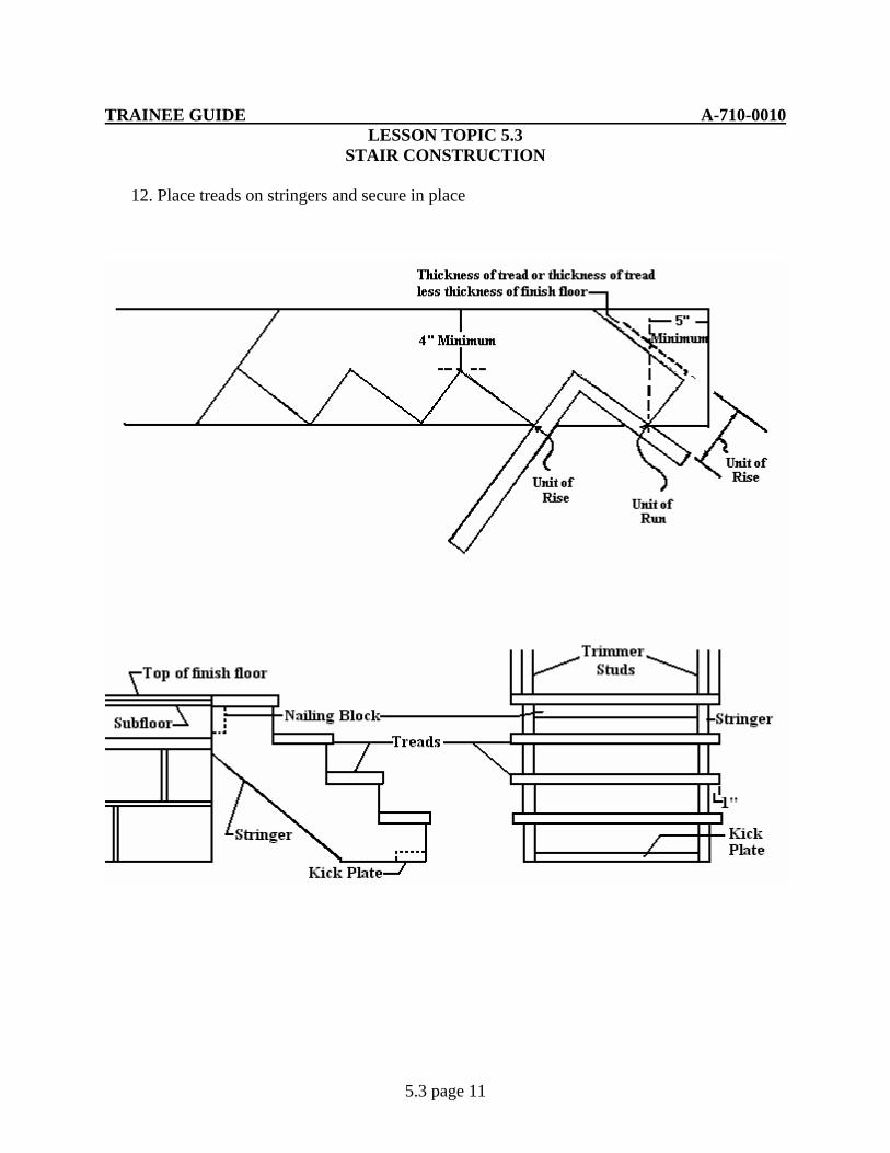
3) Unit of rise - height of one step (7 inches is the customary unit of rise)
4) Unit of run - horizontal depth of one step (10 ½ inches is the customary unit of run)
5) Riser and tread dimensions must be uniform for the length of the stair. Most standards recommend that the unit of rise and the unit of run equal 17 ½”.
3. Finding Stringer Layout Dimensions
a. Total rise
(1) Using a square, mark center of door opening on the header joist and subfloor
(2) Measure the distance from top of sub floor to top of sub floor
(3) Add the thickness of the finished flooring
(a) If the lower and upper level are to be covered with finish flooring of the same thickness, then no measurements must be added
(b) If measuring up from a finished lower level, such as a finished concrete floor, then the thickness of the upper finish flooring must be added
TRAINEE GUIDE A-710-0010 LESSON TOPIC 5.3
STAIR CONSTRUCTION
5.3 page 4
(c) If the lower and upper level are to receive flooring of a different thickness, then the difference in thickness must be added
b. Unit of rise
(1) First find the number of units of rise (steps)
(a) Divide the total rise in inches by 7 inches
(b) Round this off to the nearest whole number
EXAMPLE: The total rise is 2' 8"
1) Convert the total rise to inches
riseofunits557.4732
"32"8"24'2==÷
=+=
(2) Second step is to find the unit of rise
(a) Divide the total rise in inches by the total number of units of rise (steps)
(b) Round off this answer to the closest 1/16"
EXAMPLE: The total rise is 2' 8" and the total number of units of rise is 5
83
1664.64.16
4.65"32
===
=÷
x
6 3/8 inches = unit of rise
c. Unit of run
(1) Subtract the unit of rise from 17 1/2" (unit of rise plus unit of run)
(2) Round off the answer to the closet 1/16"
EXAMPLE: The unit of rise is 6 3/8"
runofunit==− "81118
36"2117
d. Total run
TRAINEE GUIDE A-710-0010 LESSON TOPIC 5.3
STAIR CONSTRUCTION
5.3 page 5
(1) Multiply the unit of run by the number of units of rise (steps)
Note: This step should be done in fraction format
EXAMPLE: Find the total run for the steps with 11 1/8" units of run and 5 units of rise (steps)
"855558
111 =x
e. Length of the stringer
(1) The length of the stringer is the hypotenuse of a triangle with the total run as the base and the total rise as the altitude
(a) Use the Pythagorean Theorem to find the length
EXAMPLE: Find the length of a stringer with a total rise of 32" and total run 55 5/8"
"1634'5'35.5
66.28
66.2853.2113.764.467.2
2
2
222
222
−==
=
=
=+
=+
=+
C
C
CCC
CBA
4. Stair Construction Procedures
a. Stringer layout
(1) Determine unit of rise and unit of run
(2) Select stringer material according to specifications

TRAINEE GUIDE A-710-0010 LESSON TOPIC 5.3
STAIR CONSTRUCTION
5.3 page 6
(3) Layout stringer cutouts
(a) The thickness of the tread is accounted for by making an allowance in the distance from the subfloor (lower level) to the bottom tread. This is done by subtracting the thickness of the tread from the first unit of rise. This procedure is called dropping the stringer.
(4) Check the accuracy and cut as marked
(5) Use the first stringer as a template to mark the second stringer
b. Install nailing block and kickplate
c. Install stringers in place one tread thickness below the finished floor (upper level)
d. Install treads in place according to specifications
e. Repair/replace stair members
(1) Type of damage must first be determined prior to any repairs
(a) Insect infestation such as termite or wood ants may require treatment prior to repairs
(b) Structural damage maybe caused by mother nature or mankind
(2) Tread replacement
(a) Stairway must be closed off during any type of repair for safety.
TRAINEE GUIDE A-710-0010 LESSON TOPIC 5.3
STAIR CONSTRUCTION
5.3 page 7
(b) Remove fasteners from tread. Replace tread with same size and type of material and secure to stringer.
(3) Stringer replacement
(a) Always remember safety first. Secure the stairs area from access during repair work. When replacing a damaged stringer all treads are normally removed and the damaged stringer removed. If possible, use the damaged stringer for a pattern. If this cannot be accomplished, a duplicate of the existing stringer is made. Once new stringer has been secured in place, then the treads can be reinstalled.
TRAINEE GUIDE A-710-0010 LESSON TOPIC 5.3
STAIR CONSTRUCTION
5.3 page 8
JOB SHEET 5.3-1
A. This job sheet will provide the information needed for you to construct steps
B. Equipment required
a. 16’ tape measure
b. Framing square
c. Cross cut hand saw
d. Circular saw
e. Extension cord
f. Reciprocating saw
g. 22 oz. Framing hammer
h. Saw horses
i. 2 x 12 lumber
j. 2 x 6 lumber
k. 2 x 4 lumber
l. 8d nails
m. 16d nails
C. Reference:
1. Builder 3&2 Vol.2 NAVEDTRA 12521
2. Carpentry 3rd Edition
D. Job steps:
Note: Refer to diagram sheet and Details on blue prints A-7 as necessary when performing the following task
1. Compute required measurements

TRAINEE GUIDE A-710-0010 LESSON TOPIC 5.3
STAIR CONSTRUCTION
5.3 page 9
a. Compute the total rise where the steps are to be installed
(1) Take measurement from the ground to the top of the subfloor at the center of the door opening
b. Compute the number of units of rise (steps)
(1) Divide the total rise in inches by 7 inches, round this off to the nearest whole number
c. Determine the unit of rise
(1) Divide the total rise in inches by the total number of units of rise. Round this answer off to the closest 1/16”
a) Unit of rise: _________________
d. Determine the unit run
(1) Subtract the unit of rise from 17 ½”
a) Unit of run: ________________
e. Find the total run
(1) Multiply the unit of run by the number of units of rise
a) Total run: ______________
f. Find the length of the stringer
(1) Use the Pythagorean Theorem:
a) a² + b² + c²
1) a = total run
2) b = total rise
3) c = length of stringer
(2) Length of stringer: ______________
2. Select lumber for the stringer
TRAINEE GUIDE A-710-0010 LESSON TOPIC 5.3
STAIR CONSTRUCTION
5.3 page 10
3. Layout the first cutout of the stringer
a. With the unit of run on the tongue and at the unit of rise on the blade, place the tongue on the right end of the stringer
b. Draw a line along the tongue and the blade
Note: This is the bottom tread and second riser
c. Place the tongue of the framing square flush along the bottom tread and draw a line perpendicular to the bottom tread along the blade as long as the unit of rise. This line is the first unit of rise
d. Measure and mark the thickness of the tread from the first unit of rise
Note: This point represents the unit of rise minus the thickness of the tread. This process is known as dropping the stringer
4. Layout second step cutout
a. Hold the unit of run and the unit of rise on the framing square. Place the tongue at the top of the second unit of rise
b. Draw a line along the tongue and the blade
5. Layout the balance of the cutouts using the skills and gained in step 4
6. On the layout of the last cutout extend the unit of rise line across the entire width of the stringer
7. Cut out stringers with portable electric circular saw and reciprocating saw
8. Measure, mark, and square cut the kick-plate using 2” x 4” material
Note: Use the reciprocating saw to cut out the sole plate in the doorway. This material can be used for the nailing block
9. Measure, mark, and square cut the treads from 2” x 6” material leaving specified overhang
10. Secure nailing block and kickplate to stringers with 16d common mails
11. Secure stringer assembly to box sill
TRAINEE GUIDE A-710-0010 LESSON TOPIC 5.3
STAIR CONSTRUCTION
5.3 page 11
12. Place treads on stringers and secure in place
TRAINEE GUIDE A-710-0010 LESSON TOPIC 10.1
10.1 page 1
A. Introduction
During this lesson you will how to install a door, door hardware, and window units. You will also learn to gain a hinge and repair door and windows.
B. Enabling Objectives
19.1 INSTALL a wood pre-fabricated door ensuring all members are plumb in accordance with Builder 3&2 Vol.2 NAVEDTRA 12521, Structural Journeyman Vol. CDC 3E351C, Carpentry 3rd Edition, Delmar
19.2 GAIN a hinge within specifications in accordance with Builder 3&2 Vol.2 NAVEDTRA 12521 and Carpentry 3rd Edition, Delmar
19.3 INSTALL a cylinder lock per manufacturer’s instructions in accordance with Builder 3&2 Vol.2 NAVEDTRA 12521, and Carpentry 3rd Edition, Delmar
19.4 INSTALL a window unit in accordance with Builder 3&2 Vol.2 NAVEDTRA 12521, and Carpentry 3rd Edition, Delmar
19.5 CUT glass to within +/- 1/8” of specifications in accordance with Builder 3&2 Vol.2 NAVEDTRA 12521, and Carpentry 3rd Edition, Delmar
19.6 IDENTIFY the tools and materials utilized in the installation of door, window, hardware, and glass in accordance with Builder 3&2 Vol.2 NAVEDTRA 12521, and Carpentry 3rd Edition, Delmar
19.7 DESCRIBE the installation and repair of doors, windows, hardware, glass and screen fabric in accordance with Builder 3&2 Vol.2 NAVEDTRA 12521, Structural Journeyman Vol. CDC 3E351C and Carpentry 3rd Edition, Delmar
19.8 OBSERVE all safety precautions during door and window operations in accordance with applicable instructions
C. Topic Outline
1. Introduction
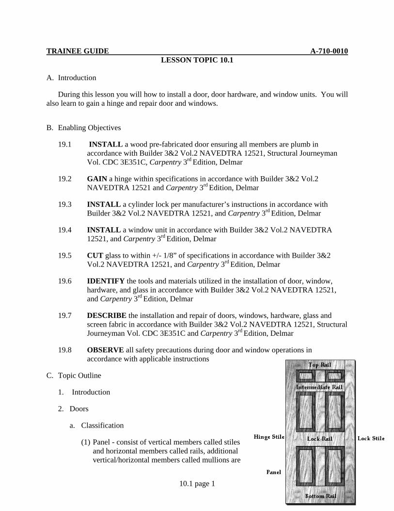
2. Doors
a. Classification
(1) Panel - consist of vertical members called stiles and horizontal members called rails, additional vertical/horizontal members called mullions are
TRAINEE GUIDE A-710-0010 LESSON TOPIC 10.1
10.1 page 2
used to divide the door into any number of panels.
(a) Stiles and rails form the framework into which panels are inserted.
(b) Panels may be solid wood, plywood, particleboard, louvers or glass inserts.
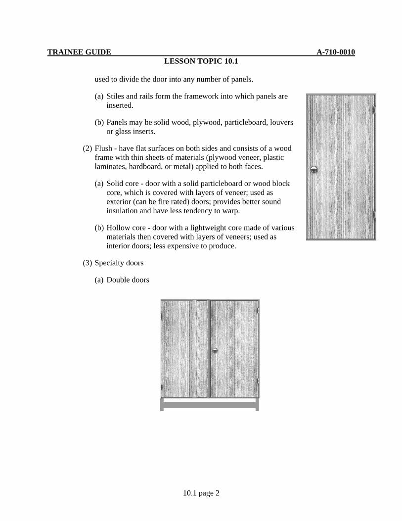
(2) Flush - have flat surfaces on both sides and consists of a wood frame with thin sheets of materials (plywood veneer, plastic laminates, hardboard, or metal) applied to both faces.
(a) Solid core - door with a solid particleboard or wood block core, which is covered with layers of veneer; used as exterior (can be fire rated) doors; provides better sound insulation and have less tendency to warp.
(b) Hollow core - door with a lightweight core made of various materials then covered with layers of veneers; used as interior doors; less expensive to produce.
(3) Specialty doors
(a) Double doors
TRAINEE GUIDE A-710-0010 LESSON TOPIC 10.1
10.1 page 3
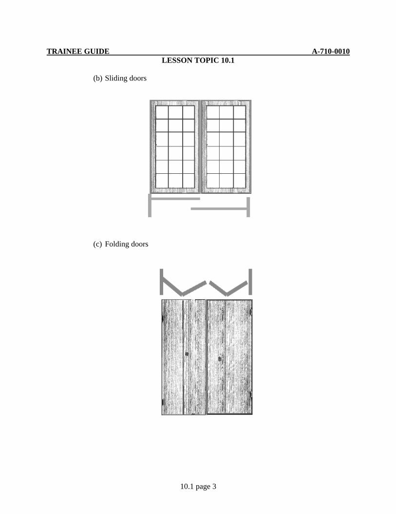
(b) Sliding doors
(c) Folding doors
TRAINEE GUIDE A-710-0010 LESSON TOPIC 10.1
10.1 page 4
b. Door frames (door jamb)
(1) Interior - made up of two side jambs, a head jamb, and stop moldings upon which the door closes against
(2) Exterior - made up of two side jambs, a head jamb, a sill and a stop
(3) Doors and frames may be fabricated in the shop and installed separately or pre-manufactured doors (pre-hung), ready for installation, may be purchased.
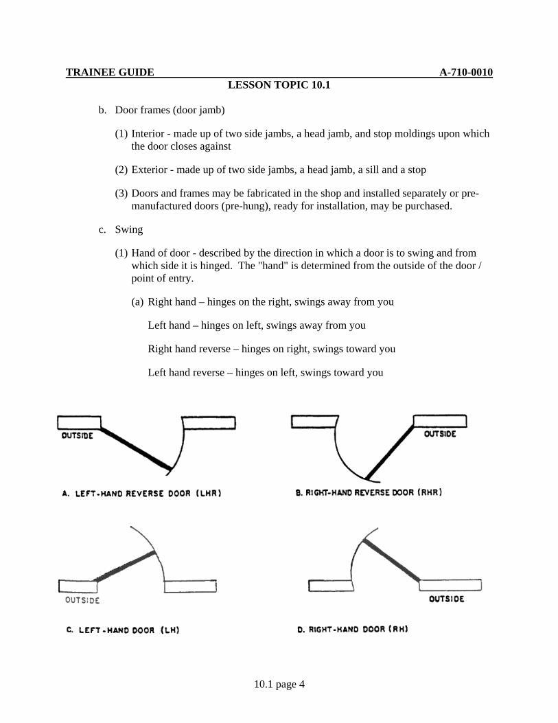
c. Swing
(1) Hand of door - described by the direction in which a door is to swing and from which side it is hinged. The "hand" is determined from the outside of the door / point of entry.
(a) Right hand – hinges on the right, swings away from you
Left hand – hinges on left, swings away from you
Right hand reverse – hinges on right, swings toward you
Left hand reverse – hinges on left, swings toward you
TRAINEE GUIDE A-710-0010 LESSON TOPIC 10.1
10.1 page 5
3. Door frame installation
a. Exterior door frame
(1) Prepare the rough opening to receive the jamb by lining the jamb with a strip of 15 pound felt 10” to 12” in width
(2) Set assembled frame into the opening and use wedges and shim to level the sill ensuring it is at the correct height (even with the finished floor)
(3) Once sill is level, place wedges at the bottom between the side jamb and trimmer studs on each side and drive a 16d casing nail through the jamb and edge into the trimmer stud (DO NOT SET THE NAILS AT THIS TIME)
(4) Place additional wedges up the jamb behind the hinge and lock, work the wedges until the frame is plumb, then drive the 16d casing nails through each wedge
b. Interior doorframe
(1) Set assembled frame into rough opening, ensuring the head jamb is level
(2) Place wedges between jamb and trimmer at the top on one side and drive two 8d finish nails (all nails should be driven where they will be covered by the door stop) work down the jamb ensuring that it is plumb
(3) Repeat this process for the other side jamb and secure the door stop in place
4. Door hardware
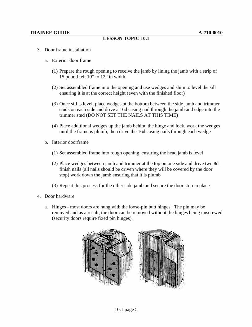
a. Hinges - most doors are hung with the loose-pin butt hinges. The pin may be removed and as a result, the door can be removed without the hinges being unscrewed (security doors require fixed pin hinges).
TRAINEE GUIDE A-710-0010 LESSON TOPIC 10.1
10.1 page 6
(1) Doors should be hinged so they:
(a) Open in the direction of the natural entry.
(b) Open out in public buildings
(c) Swing against a blank wall whenever possible and never into a hallway.
(2) Number of hinges
(a) Exterior doors - use 3 hinges
1) To reduce warp caused by the difference in exposure on the opposite side
2) To support wider and heavier exterior doors
(b) Interior doors - use 2 or 3 hinges depending on the type of the door
(3) Terms
(a) Gain – is the cutout or mortise made to receive a leaf of the hinge
1) Depth - determined by the thickness of the hinge
2) Width - determined by the size of the hinge
(b) Setback - the distance that the hinge is placed away from the side of the door
1) Standard is 3/16 of inch
TRAINEE GUIDE A-710-0010 LESSON TOPIC 10.1
10.1 page 7
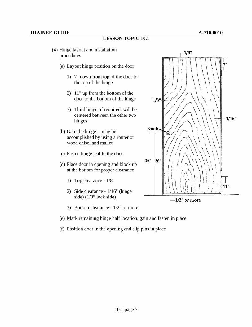
(4) Hinge layout and installation procedures
(a) Layout hinge position on the door
1) 7" down from top of the door to the top of the hinge
2) 11" up from the bottom of the door to the bottom of the hinge
3) Third hinge, if required, will be centered between the other two hinges
(b) Gain the hinge -- may be accomplished by using a router or wood chisel and mallet.
(c) Fasten hinge leaf to the door
(d) Place door in opening and block up at the bottom for proper clearance
1) Top clearance - 1/8"
2) Side clearance - 1/16" (hinge side) (1/8” lock side)
3) Bottom clearance - 1/2" or more
(e) Mark remaining hinge half location, gain and fasten in place
(f) Position door in the opening and slip pins in place

TRAINEE GUIDE A-710-0010 LESSON TOPIC 10.1
10.1 page 8
b. Locks
(1) Cylinder locks - sturdy heavy duty locks designed for installation in exterior doors and provide high security
(2) Tubular locks - light duty, used for interior doors on bathrooms, bedrooms, passages and closets
(3) Install according to instructions provided with lock.
NOTE: The basic following procedures will normally apply
(a) Measure up from the floor to the centerline of the lock, normally position is between 36” and 40”, mark a square mark across the edge and stile of the door
(b) Position the template (supplied with lock) on the lines and mark the center of the holes to be bored
TRAINEE GUIDE A-710-0010 LESSON TOPIC 10.1
10.1 page 9
(c) Bore the hole through the side of the door first, then the hole on the edge. Be sure to drill the holes in accordance with manufactures specifications. To avoid angled holes a boring jig can be used
(d) After all holes are bored, insert the latch into the door edge and mark around it’s face plate. Recess that area so that the latch rest flush against the edge of the door.
(e) Reposition the latch into the hole and install the rest of the lock according to manufactures specifications.
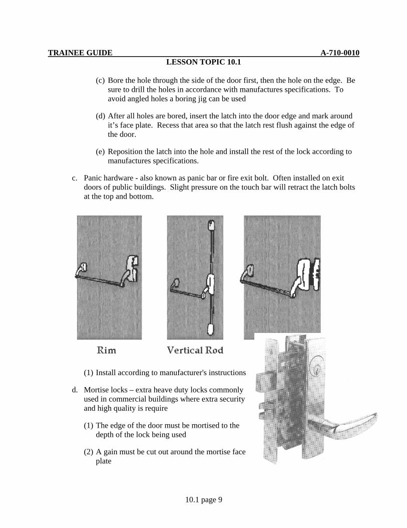
c. Panic hardware - also known as panic bar or fire exit bolt. Often installed on exit doors of public buildings. Slight pressure on the touch bar will retract the latch bolts at the top and bottom.
(1) Install according to manufacturer's instructions
d. Mortise locks – extra heave duty locks commonly used in commercial buildings where extra security and high quality is require
(1) The edge of the door must be mortised to the depth of the lock being used
(2) A gain must be cut out around the mortise face plate
TRAINEE GUIDE A-710-0010 LESSON TOPIC 10.1
10.1 page 10
(3) Refer to manufacture’s instruction for exact specifications
e. Cipher lock – locking device designed to allow keyless entry into high security areas. The combination is coded into the lock allowing access to authorized personnel only
(1) Install according to manufacturer’s instructions
f. Door closer - device that closes a door and controls the speed and closing action of the door.
(1) Install according to manufacturer's instructions
5. Windows
a. Parts
(1) Sash - fixed or movable framework of a window that contains/holds the glass.
(2) Muntin - separates the window into panes
(3) Pane - single piece of glass in a door or window, also called "lights"
(4) Frame - used to hold the window in place
b. Types
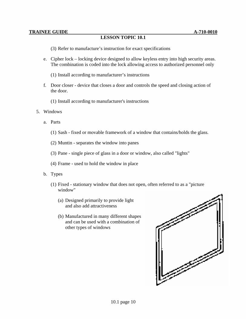
(1) Fixed - stationary window that does not open, often referred to as a "picture window"
(a) Designed primarily to provide light and also add attractiveness
(b) Manufactured in many different shapes and can be used with a combination of other types of windows

TRAINEE GUIDE A-710-0010 LESSON TOPIC 10.1
10.1 page 11
(2) Sliding - windows in which the sashes slide either vertically or horizontally
(a) Double-hung – upper and lower sashes slide vertically in track/grooves in the frame
1) Sash is provided with springs, balances, or compression weather stripping to hold it in an open vertical position
(b) Horizontal sliding – sashes slide horizontally in the frame
(c) Single hung – similar to double hung with the main difference being the upper sash is fixed

TRAINEE GUIDE A-710-0010 LESSON TOPIC 10.1
10.1 page 12
(3) Swinging - windows which are hinged to swing open
(a) Casement - side-hinged sash, usually designed to swing outward
1) In-swing type is very difficult to make weather tight
(b) Awning - hinged at the top and swings out at the bottom; often combined with a fixed window to provide ventilation
(c) Hopper - similar to awning windows, except they are hinged at the bottom and swing in or out
TRAINEE GUIDE A-710-0010 LESSON TOPIC 10.1
10.1 page 13
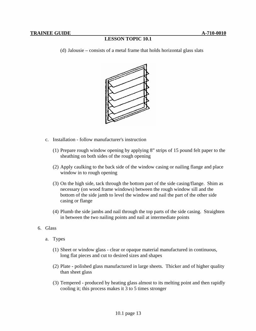
(d) Jalousie – consists of a metal frame that holds horizontal glass slats
c. Installation - follow manufacturer's instruction
(1) Prepare rough window opening by applying 8” strips of 15 pound felt paper to the sheathing on both sides of the rough opening
(2) Apply caulking to the back side of the window casing or nailing flange and place window in to rough opening
(3) On the high side, tack through the bottom part of the side casing/flange. Shim as necessary (on wood frame windows) between the rough window sill and the bottom of the side jamb to level the window and nail the part of the other side casing or flange
(4) Plumb the side jambs and nail through the top parts of the side casing. Straighten in between the two nailing points and nail at intermediate points
6. Glass
a. Types
(1) Sheet or window glass - clear or opaque material manufactured in continuous, long flat pieces and cut to desired sizes and shapes
(2) Plate - polished glass manufactured in large sheets. Thicker and of higher quality than sheet glass
(3) Tempered - produced by heating glass almost to its melting point and then rapidly cooling it; this process makes it 3 to 5 times stronger

TRAINEE GUIDE A-710-0010 LESSON TOPIC 10.1
10.1 page 14
(a) Withstands heavy impact and greater pressure
(4) Insulating - two or more sheets of glass separated by an air space; the air space is free of moisture, thereby slowing down the transfer of heat
(5) Wired - glass which wire mesh is embedded between the two faces. Used to prevent the glass from shattering if it breaks
(6) Laminated - two or more sheets of flat glass laminated together using a layer of transparent plastic to prevent shattering
(7) Obscure - translucent glass, such as frosted or ground glass, which allows passage of light but obstructs vision.
b. Measuring and cutting glass
(1) Measure the length and width of the opening and then deduct 1/8" from the length and width to allow for expansion and contraction
(2) Equipment needed
(a) Flat, clean, solid table
(b) Tape measure
(c) Straightedge
(d) Glass cutter
(3) Procedures
(a) Mark glass at desired location
(b) Lubricate glass cutter wheel with machine oil or kerosene
(c) Mark start of cutting line by lightly nicking the edge of the glass with the cutter
TRAINEE GUIDE A-710-0010 LESSON TOPIC 10.1
10.1 page 15
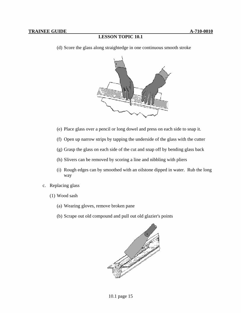
(d) Score the glass along straightedge in one continuous smooth stroke
(e) Place glass over a pencil or long dowel and press on each side to snap it.
(f) Open up narrow strips by tapping the underside of the glass with the cutter
(g) Grasp the glass on each side of the cut and snap off by bending glass back
(h) Slivers can be removed by scoring a line and nibbling with pliers
(i) Rough edges can by smoothed with an oilstone dipped in water. Rub the long way
c. Replacing glass
(1) Wood sash
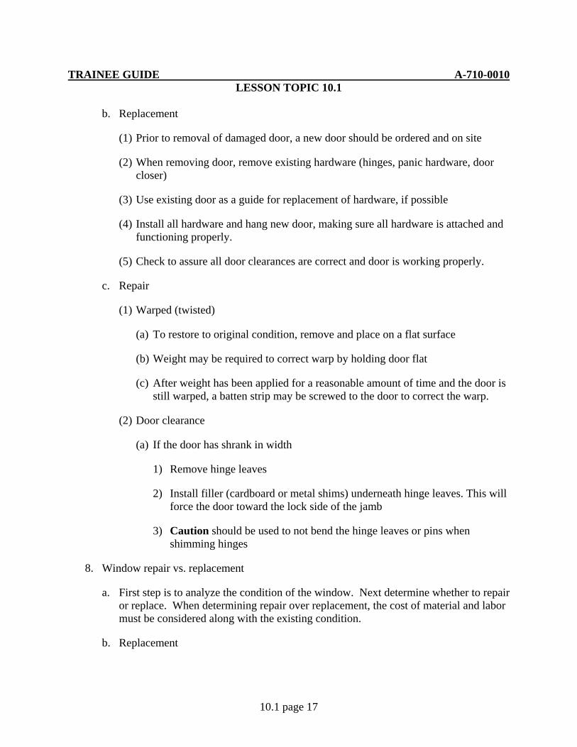
(a) Wearing gloves, remove broken pane
(b) Scrape out old compound and pull out old glazier's points

TRAINEE GUIDE A-710-0010 LESSON TOPIC 10.1
10.1 page 16
(c) Paint the raw wood with a sealer or primer so it won't absorb oil from the fresh compound
(d) Apply a bead of glazing compound to the frame
(e) Set the new pane against the compound and press firmly
(f) Install new glazier's points
(g) Apply a bead of glazing compound and smooth with a putty knife.
(2) Metal sash
(a) Gasket and mastic
1) Pry gasket out of sash
2) Wearing gloves, remove broken glass
3) With a putty knife, apply mastic to new pane's edge
4) Press glued edges gently against sash
5) Reinstall gaskets
(b) U-shaped gaskets
1) Unscrew the corners to release one side of the sash
2) Take side piece off, and pull broken glass out of the gasket
3) Fit the gasket around the new pane
4) Slide new pane into the three-sided sash
5) Reattach the side pieces
7. Door repair/replacement
a. Replacement vs. repair
(1) First step is to analyze the condition of the door. Next, determine whether to repair or replace will have to be made. When determining repair over replacement, cost of material and labor must be considered along with the existing condition.
TRAINEE GUIDE A-710-0010 LESSON TOPIC 10.1
10.1 page 17
b. Replacement
(1) Prior to removal of damaged door, a new door should be ordered and on site
(2) When removing door, remove existing hardware (hinges, panic hardware, door closer)
(3) Use existing door as a guide for replacement of hardware, if possible
(4) Install all hardware and hang new door, making sure all hardware is attached and functioning properly.
(5) Check to assure all door clearances are correct and door is working properly.
c. Repair
(1) Warped (twisted)
(a) To restore to original condition, remove and place on a flat surface
(b) Weight may be required to correct warp by holding door flat
(c) After weight has been applied for a reasonable amount of time and the door is still warped, a batten strip may be screwed to the door to correct the warp.
(2) Door clearance
(a) If the door has shrank in width
1) Remove hinge leaves
2) Install filler (cardboard or metal shims) underneath hinge leaves. This will force the door toward the lock side of the jamb
3) Caution should be used to not bend the hinge leaves or pins when shimming hinges
8. Window repair vs. replacement
a. First step is to analyze the condition of the window. Next determine whether to repair or replace. When determining repair over replacement, the cost of material and labor must be considered along with the existing condition.
b. Replacement

TRAINEE GUIDE A-710-0010 LESSON TOPIC 10.1
10.1 page 18
(1) If replacement has been determined due to extensive decay or damage a new window must be installed
(2) Replacement procedures
(a) Remove existing window and trim as required. Obtain a new window unit of the same size and type prior to removal
(b) Install new window unit seal and trim as required
(3) Repair of window
(a) Double hung window (window top and bottom sashes slide up and down)
1) When windows have been painted, they may become sealed shut
a) Loosen the sash from the stops by inserting a putty knife between the sash and stops
b) Use a hammer and block of wood to gently loosen the paint from the sash and stop if there is not enough room for a putty knife
c) Caution should be used to not damage the sash or stop. If the sash is in poor condition the glass can easily be broken using the above methods
2) Common faults and remedies
a) Binding sash along stops – wax-binding surface with bees wax or similar product. If problem persists remove and plane stops (sanding or scraping maybe adequate)
b) Binding due to swollen sash – remove stops, then remove sash from frame. Sand to proper fit and reinstall sash and stops
c) Bowing stops – Remove stop and cut to proper length and reinstall
d) Wooden jambs with jamb liners made of aluminum / plastic – when sash is sticking a light coat of silicone lubricant may be directly applied to jamb liner
Caution never drive nails or screws through liners
9. Replacement of window / door screen
a. Types

TRAINEE GUIDE A-710-0010 LESSON TOPIC 10.1
10.1 page 19
(1) Fiberglass mesh
(2) Aluminum mesh
b. Replacement procedure
(1) Cut screen approximately 2 inches larger than opening
(2) Roll screen into base strip using a spline and screening tool
(3) Start by rolling top horizontal, then roll the sides and finish with the bottom, making sure to keep screen tight
(4) Finish by trimming all excess screen with a razor knife using all safety precautions

TRAINEE GUIDE A-710-0010 LESSON TOPIC 10.1
10.1 page 20
JOB SHEET 10.1-1
A. This job sheet will provide the information needed for you install a door and window
B. Equipment required
1. 16’ tape measure
2. Cross cut hand saw
3. 22 oz. Framing hammer
4. Variable speed drill 3/8”
5. 4’ level
6. Phillips bit # 2
7. Phillips #2 screwdriver
8. 3” sheet rock screws
9. Wooden shims
10. Shingle hung window
11. Pre-hung Exterior door
C. Reference:
1. Builder 3&2 Vol.2 NAVEDTRA 12521
2. Carpentry 3rd Edition, Delmar
D. Job steps:
1. Install a pre-hung door
a. Position door unit in the rough opening. Door should be in the closed position with spacers between the door and the frame to ensure the proper clearances are maintained
b. Level the sill. Ensure that the inside of the jamb extends 1/2" past the interior wall to allow for sheetrock butting to it. Install shims (behind the hinge location on hinge side and approx. 6" up on other side) between the side jambs and the trimmer studs at the bottom. There should be approximately 3/8" - 1/2" gap between the trimmer stud and side jamb. Secure frame through the side jambs and shims with wood screws
TRAINEE GUIDE A-710-0010 LESSON TOPIC 10.1
10.1 page 21
NOTE: Casing nails would normally be used instead of screws. For purposes of door reuse, screws are used
c. Plumb the side jamb working from the bottom up. Shim at the top behind the top hinge location and approx. 4" down from the top on the other side. Secure the frame through the side jambs and shims with wood screws
d. Install intermediate shims. On hinge side, place shims centered between the first two. On lock side, place shims behind strike plate location
e. Open door to see if it operates properly. Add additional screws, if needed
NOTE: Inspect quality of work and check with the instructor
2. Install a window
a. Drill holes through the flange if none are present
(1) Ensure there are three holes in the flange on each side of the window. One screw in each corner (top/bottom) and one centered all around
NOTE: There will be a total of eight holes in the entire flange
b. Lift the window in place. Run a screw into one of the top corners
c. Plumb the window and place a screw in the opposite top corner
d. Work around the perimeter placing screws in the remaining holes
NOTE: Inspect the quality of your work and check with the instructor
TRAINEE GUIDE A-710-0010 LESSON TOPIC 10.1
DOORS AND WINDOWS
10.1 page 22
JOB SHEET 10.1-2
A. This job sheet will provide the information needed for you install a cylinder lock in a door
B. Equipment required
a. Phillips #2 screwdriver
b. Lock set
c. Wooden wedges
d. Pre-hung door
C. Reference:
1. Builder 3&2 Vol.2 NAVEDTRA 12521
2. Carpentry 3rd Edition, Delmar
D. Job steps:
Note: There is a large variety of lock manufacturers on the market; this is just one of many applications used
1. Open the door to a convenient working position and place wedges under the bottom near the outer edge to hold the door in place
2. Install the latch bolt in the bolt hole ensuring beveled edge is facing outward. Fasten latch bolt in place with screw
3. Insert lock assembly from outside of door
a. Press tube against curved back of bolt while pushing the sock into the cross hole
b. The tabs on the housing must engage with slots in bolt
4. Determine which side of the clamp plate should be out. Install over screws, turn to hold in place and tighten screws
5. Snap rose in place, aligning notch with tab
6. Align slot on top of knob with peg, press peg in and push on knob
7. Secure striker plate to jamb with screws

TRAINEE GUIDE A-710-0010 LESSON TOPIC 10.1
DOORS AND WINDOWS
10.1 page 23
8. To remove reverse installation procedures

TRAINEE GUIDE A-710-0010 LESSON TOPIC 10.1
DOORS AND WINDOWS
10.1 page 24
JOB SHEET 10.1-3
A. This job sheet will provide the information needed to gain a hinge
B. Equipment required
1. 2” x4” lumber
2. Pencil
3. Hinge
4. Wooden mallet
5. Wood chisel
C. Reference:
1. Builder 3&2 Vol.2 NAVEDTRA 12521
2. Carpentry 3rd Edition, Delmar
D. Job steps:
1. Position the hinge firmly on the lumber at marked location. Allow 3/16” for setback, mark cutout line around the hinge with a pencil
2. Mark the depth against the side of the lumber
3. Gain the hinge
a. Using a chisel and mallet, score the hinge cutout lines to the proper depth
b. At 1/8” or less intervals and flat side of the chisel out, score a series of depth cuts across the hinge area
c. Holding the chisel flat, bevel side up, and working from jamb edge at the proper depth, remove previously scored area
Note: continually check the gain with the hinge to ensure proper fit
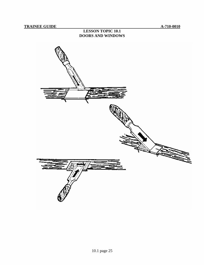
TRAINEE GUIDE A-710-0010 LESSON TOPIC 10.1
DOORS AND WINDOWS
10.1 page 25
TRAINEE GUIDE A-710-0010 LESSON TOPIC 10.1
DOORS AND WINDOWS
10.1 page 26
JOB SHEET 10.1-4
A. This job sheet will provide the information needed to guide you though the process of cutting sheet glass
B. Equipment required:
1. Framing square
2. Glass cutter
3. Pliers
4. Sheet glass 12” x 12”
5. Gloves
C. References:
1. Builder 3&2 Vol.2 NAVEDTRA 12521
2. Carpentry 3rd Edition
D. Job steps:
1. Lay a straight edge or framing square along the proposed cut
a. You will need to cut two pieces 5” x 8”
2. Hold the cutter by resting your index finger on the flat part of the handle and make one continuous smooth stroke along the surface of the glass with the side of the cutter pressed against the straight edge.
3. Snap the glass immediately after cutting (scoring) by placing a pencil or long dowel under the score line and pressing with your hands on each side
4. To cut a narrow strip from a large piece of glass, score a line and then tap gently underneath the scored line. Grasp the glass on each side of the line and gently snap off the waste piece
5. If glass does not break off cleanly, nibble it off with pliers or the notches in the cutter
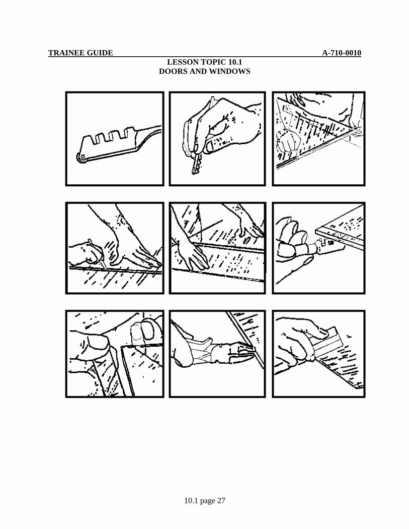
TRAINEE GUIDE A-710-0010 LESSON TOPIC 10.1
DOORS AND WINDOWS
10.1 page 27

TRAINEE GUIDE A-710-0010 LESSON TOPIC 5.4 ROOF FRAMING
5.4 page 1
A. Introduction
During this lesson you will learn how to construct and repair a roof frame, to include computing the length of all components.
B. Enabling Objectives
12.1 IDENTIFY roof framing components, installation and repair/replacement methods in accordance with Builder 3&2 Vol.2 NAVEDTRA 12521 and Carpentry 3rd Edition, Delmar
12.2 CALCULATE roof framing measurements to the nearest 1/16" in accordance with Builder 3&2 Vol.2 NAVEDTRA 12521 and Carpentry 3rd Edition, Delmar
12.3 PERFORM double top plate and ridge board layout in accordance with Builder 3&2 Vol.2 NAVEDTRA 12521 and Carpentry 3rd Edition, Delmar
12.4 LAYOUT a rafter, collar tie, ceiling joists and gable end studs within a 1/16" of specified lengths in accordance with Builder 3&2 Vol.2 NAVEDTRA 12521 and Carpentry 3rd Edition, Delmar
12.5 CUT a rafter, collar tie, ceiling joists and gable end studs to within +/- 1/8" of specified lengths in accordance with Builder 3&2 Vol.2 NAVEDTRA 12521 and Carpentry 3rd Edition, Delmar
12.6 INSTALL ceiling joists and rafters to within 1/8" of specified location in accordance with Builder 3&2 Vol.2 NAVEDTRA 12521 and Carpentry 3rd Edition, Delmar
12.7 INSTALL gable end studs to within 1/8" of specified location in accordance with Builder 3&2 Vol.2 NAVEDTRA 12521 and Carpentry 3rd Edition, Delmar
12.8 OBSERVE all safety precautions during roof framing operations in accordance with applicable instructions
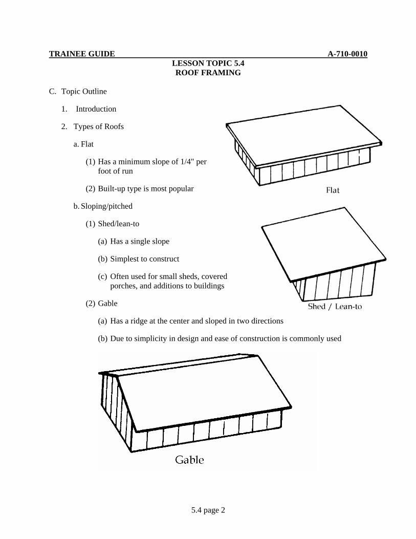
TRAINEE GUIDE A-710-0010 LESSON TOPIC 5.4 ROOF FRAMING
5.4 page 2
C. Topic Outline
1. Introduction
2. Types of Roofs
a. Flat
(1) Has a minimum slope of 1/4" per foot of run
(2) Built-up type is most popular
b. Sloping/pitched
(1) Shed/lean-to
(a) Has a single slope
(b) Simplest to construct
(c) Often used for small sheds, covered porches, and additions to buildings
(2) Gable
(a) Has a ridge at the center and sloped in two directions
(b) Due to simplicity in design and ease of construction is commonly used
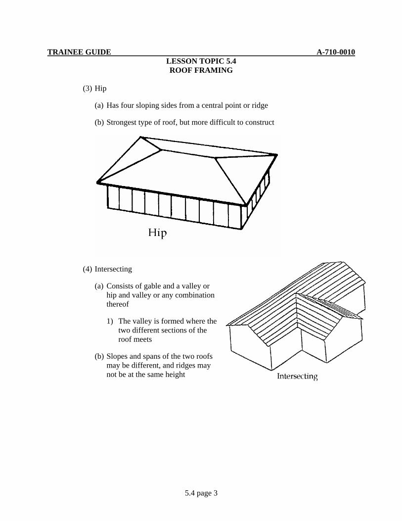
TRAINEE GUIDE A-710-0010 LESSON TOPIC 5.4 ROOF FRAMING
5.4 page 3
(3) Hip
(a) Has four sloping sides from a central point or ridge
(b) Strongest type of roof, but more difficult to construct
(4) Intersecting
(a) Consists of gable and a valley or hip and valley or any combination thereof
1) The valley is formed where the two different sections of the roof meets
(b) Slopes and spans of the two roofs may be different, and ridges may not be at the same height
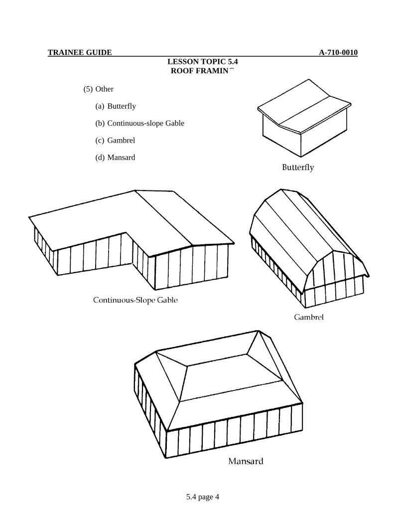
TRAINEE GUIDE A-710-0010 LESSON TOPIC 5.4 ROOF FRAMING
5.4 page 4
(5) Other
(a) Butterfly
(b) Continuous-slope Gable
(c) Gambrel
(d) Mansard
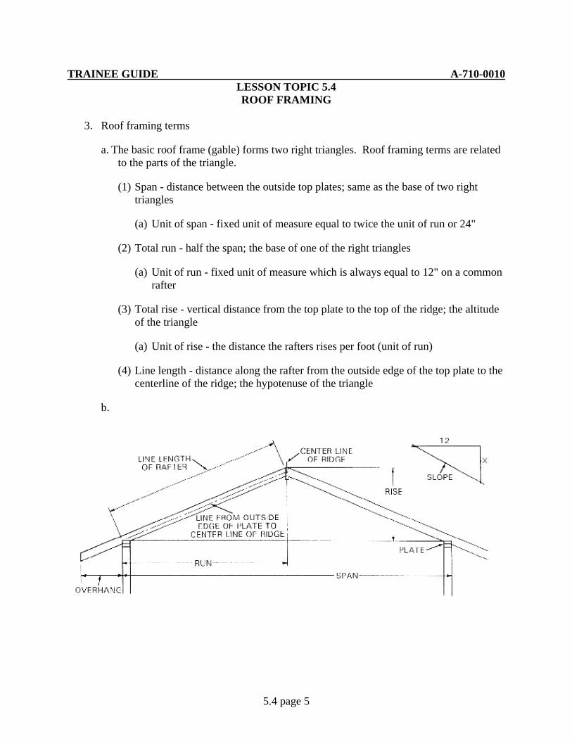
TRAINEE GUIDE A-710-0010 LESSON TOPIC 5.4 ROOF FRAMING
5.4 page 5
3. Roof framing terms
a. The basic roof frame (gable) forms two right triangles. Roof framing terms are related to the parts of the triangle.
(1) Span - distance between the outside top plates; same as the base of two right triangles
(a) Unit of span - fixed unit of measure equal to twice the unit of run or 24"
(2) Total run - half the span; the base of one of the right triangles
(a) Unit of run - fixed unit of measure which is always equal to 12" on a common rafter
(3) Total rise - vertical distance from the top plate to the top of the ridge; the altitude of the triangle
(a) Unit of rise - the distance the rafters rises per foot (unit of run)
(4) Line length - distance along the rafter from the outside edge of the top plate to the centerline of the ridge; the hypotenuse of the triangle
b.
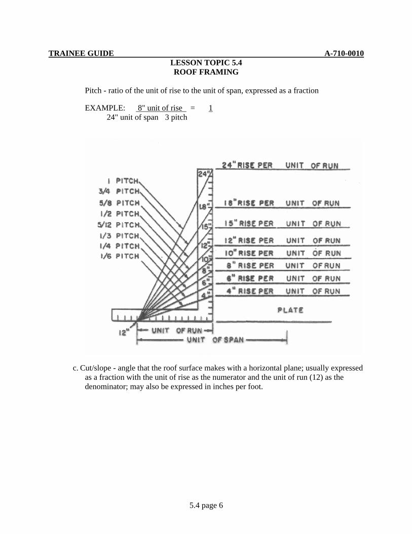
TRAINEE GUIDE A-710-0010 LESSON TOPIC 5.4 ROOF FRAMING
5.4 page 6
Pitch - ratio of the unit of rise to the unit of span, expressed as a fraction
EXAMPLE: 8" unit of rise = 1 24" unit of span 3 pitch
c. Cut/slope - angle that the roof surface makes with a horizontal plane; usually expressed as a fraction with the unit of rise as the numerator and the unit of run (12) as the denominator; may also be expressed in inches per foot.
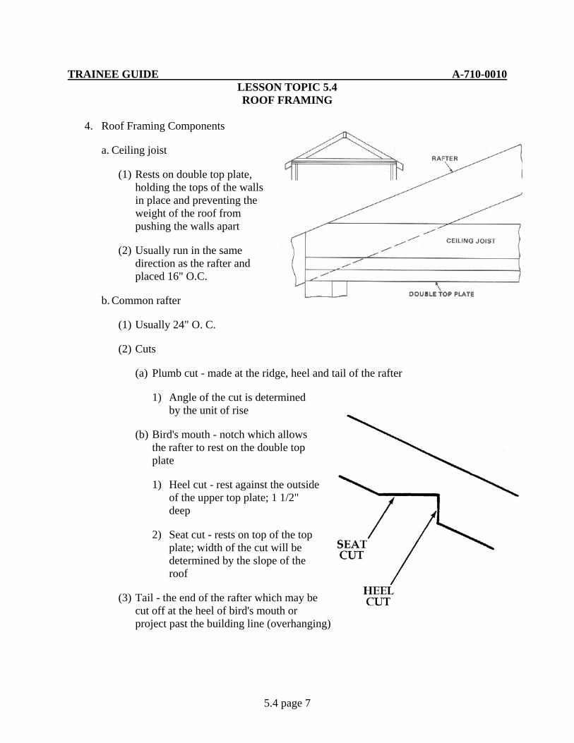
TRAINEE GUIDE A-710-0010 LESSON TOPIC 5.4 ROOF FRAMING
5.4 page 7
4. Roof Framing Components
a. Ceiling joist
(1) Rests on double top plate, holding the tops of the walls in place and preventing the weight of the roof from pushing the walls apart
(2) Usually run in the same direction as the rafter and placed 16" O.C.
b. Common rafter
(1) Usually 24" O. C.
(2) Cuts
(a) Plumb cut - made at the ridge, heel and tail of the rafter
1) Angle of the cut is determined by the unit of rise
(b) Bird's mouth - notch which allows the rafter to rest on the double top plate
1) Heel cut - rest against the outside of the upper top plate; 1 1/2" deep
2) Seat cut - rests on top of the top plate; width of the cut will be determined by the slope of the roof
(3) Tail - the end of the rafter which may be cut off at the heel of bird's mouth or project past the building line (overhanging)
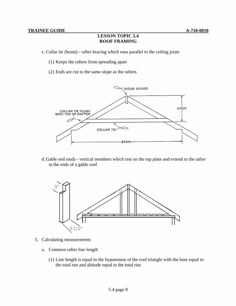
TRAINEE GUIDE A-710-0010 LESSON TOPIC 5.4 ROOF FRAMING
5.4 page 8
c. Collar tie (beam) - rafter bracing which runs parallel to the ceiling joists
(1) Keeps the rafters from spreading apart
(2) Ends are cut to the same slope as the rafters
d. Gable end studs - vertical members which rest on the top plate and extend to the rafter in the ends of a gable roof
5. Calculating measurements
a. Common rafter line length
(1) Line length is equal to the hypotenuse of the roof triangle with the base equal to the total run and altitude equal to the total rise

TRAINEE GUIDE A-710-0010 LESSON TOPIC 5.4 ROOF FRAMING
5.4 page 9
(2) For calculating purposes a similar triangle is used with the hypotenuse equal to the bridge measurement, the base equal to the unit of run and the altitude equal to the unit of rise
(a) Bridge measurement is found using the Pythagorean Theorem:
A2 + B2 = C2
(b) Line length (LL) is found using the following formula:
Bridge measure (") x total run (') = LL (")
EXAMPLE: Find the line length of a common rafter of a building with a 22' span and 6" unit of rise
1) Total run
22' ÷ 2 = 11'
2) Bridge measure
A2 + B2 = C2
62 + 122 = C2
36 + 144 = C2
3) Line length
13.42 (bridge measure) x 11' (total run) 147.62" = 12' 3 5/8" EXAMPLE 2: Find the line length of a common rafter of a roof with a 20' span and 4" unit of rise
1) Total run
20' ÷ 2 = 10'
2) Bridge Measure
A2 + B2 = C2
42 + 122 = C2
16 + 144 = C2
C = 160 C = 12.65"
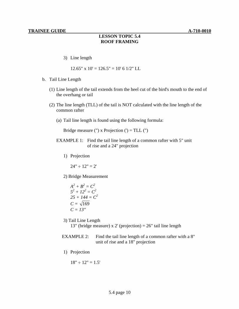
TRAINEE GUIDE A-710-0010 LESSON TOPIC 5.4 ROOF FRAMING
5.4 page 10
3) Line length 12.65" x 10' = 126.5" = 10' 6 1/2" LL
b. Tail Line Length
(1) Line length of the tail extends from the heel cut of the bird's mouth to the end of the overhang or tail
(2) The line length (TLL) of the tail is NOT calculated with the line length of the common rafter
(a) Tail line length is found using the following formula:
Bridge measure (") x Projection (') = TLL (")
EXAMPLE 1: Find the tail line length of a common rafter with 5" unit of rise and a 24" projection
1) Projection
24" ÷ 12" = 2'
2) Bridge Measurement
A2 + B2 = C2
52 + 122 = C2
25 + 144 = C2
C = 169 C = 13" 3) Tail Line Length 13" (bridge measure) x 2' (projection) = 26" tail line length
EXAMPLE 2: Find the tail line length of a common rafter with a 8" unit of rise and a 18" projection
1) Projection
18" ÷ 12" = 1.5'
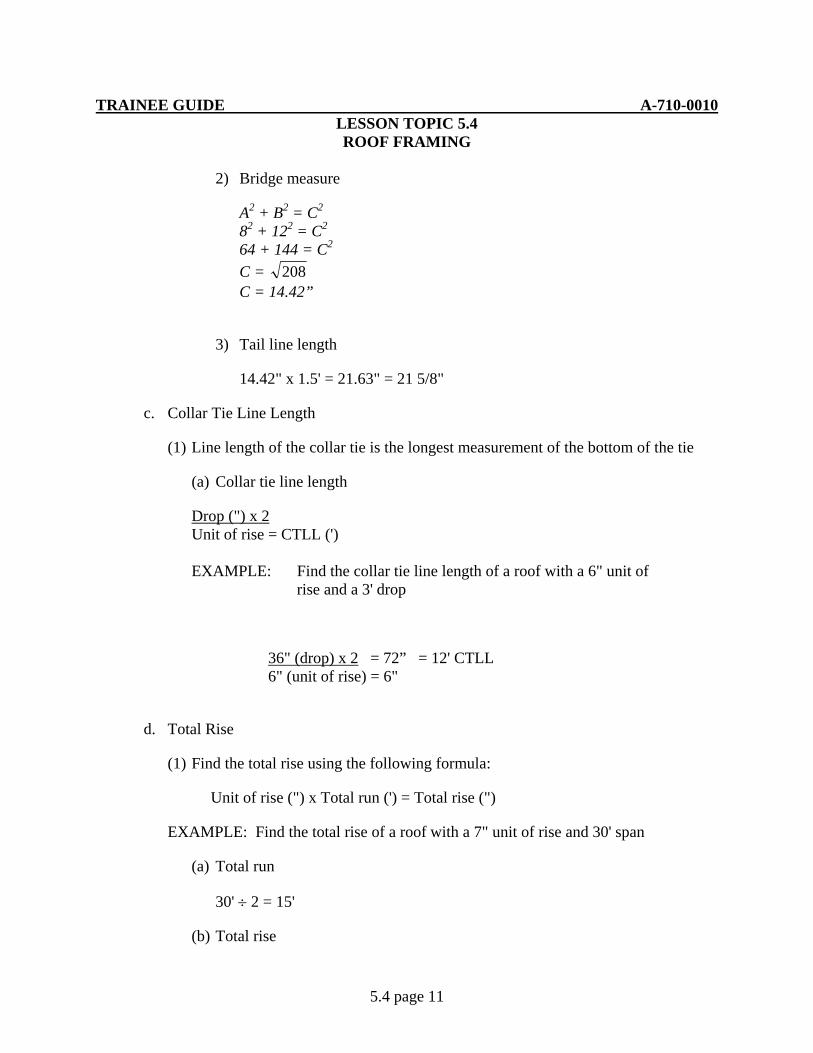
TRAINEE GUIDE A-710-0010 LESSON TOPIC 5.4 ROOF FRAMING
5.4 page 11
2) Bridge measure
A2 + B2 = C2
82 + 122 = C2
64 + 144 = C2
C = 208 C = 14.42”
3) Tail line length
14.42" x 1.5' = 21.63" = 21 5/8"
c. Collar Tie Line Length
(1) Line length of the collar tie is the longest measurement of the bottom of the tie
(a) Collar tie line length
Drop (") x 2 Unit of rise = CTLL (') EXAMPLE: Find the collar tie line length of a roof with a 6" unit of
rise and a 3' drop
36" (drop) x 2 = 72” = 12' CTLL 6" (unit of rise) = 6"
d. Total Rise
(1) Find the total rise using the following formula:
Unit of rise (") x Total run (') = Total rise (")
EXAMPLE: Find the total rise of a roof with a 7" unit of rise and 30' span
(a) Total run
30' ÷ 2 = 15'
(b) Total rise

TRAINEE GUIDE A-710-0010 LESSON TOPIC 5.4 ROOF FRAMING
5.4 page 12
7" (unit of rise) x 15' (total run) 105" = 8' 9" total rise
(2) Height of the Ridge board
(a) The height of the ridge board is the distance from the top of the top plate to the top of the ridge board
(b) Height is found using the following formula:
Total rise + Thickness above the bird's mouth
(c) EXAMPLE: find the height of the ridge board of a roof with a total rise of 8’ and thickness above the bird mouth of 2 ½
8’
+ 2 ½”
8’ 2 ½”
e. Common difference In The Gable End Stud Line Length
(1) The lengths of gable end studs increases proportionally based on the slope of the roof
(a) The formula for finding the common difference is the length of the gable end stud is:
Common difference in the Unit of Rise X Line Length of Gable End StudUnit of Run On Center Spacing (b) EXAMPLE: Find the common difference in the line length of the gable end
studs of a roof with a 6” unit of rise 16” O.C.
6 : 12 :: X : 16
12 X = 6 X 16
12X = 96
X = 8” (common difference)
TRAINEE GUIDE A-710-0010 LESSON TOPIC 5.4 ROOF FRAMING
5.4 page 13
6. Major Steps of Roof Framing
a. Layout the top plate for ceiling joists and rafters
b. Layout ceiling joists
c. Layout the common rafter
(1) Layout rafter line length
(2) Layout the bird's mouth
(3) Layout tail line length
(4) Layout the plumb cut at the ridge board (shortening allowance)
(a) Subtract one half the thickness of the ridge board
(5) Layout the collar tie
d. Layout the ridge board
(1) If the ridge board is not long enough to span the length of the roof plus the overhang, and joints are necessary, each should be cut so that the joint falls in the center of a rafter
e. Layout the gable end studs
f. Install ceiling joists
g. Raise the roof frame
(1) Assemble rafters and collar ties
(2) Install ridge board
(3) Install rafter and collar tie assembly
(4) Install gable end studs

TRAINEE GUIDE A-710-0010 LESSON TOPIC 5.4 ROOF FRAMING
5.4 page 14
h. Repair / replace ceiling joist and/or rafters
(1) Type of damage must first be determined prior to any repairs.
(a) Insect infestation such as termite or wood ants may require treatment prior to repairs
(b) Structural damage may be caused by mother nature or mankind
(2) Ceiling joist that is cracked/broken can be jacked into place leaving existing covering in place. Lumber of the same size can be installed next to the existing broken joist. This process is known as scabbing
(3) If the ceiling joist must be replaced due to excessive damage, the interior covering must be removed. Once covering is removed, damaged joist should be replaced. While removing joist, additional support may be needed. Install new member and secure. Replace covering to match existing
7. Trusses
a. Definition - an assembly of members forming a rigid framework of triangular shapes
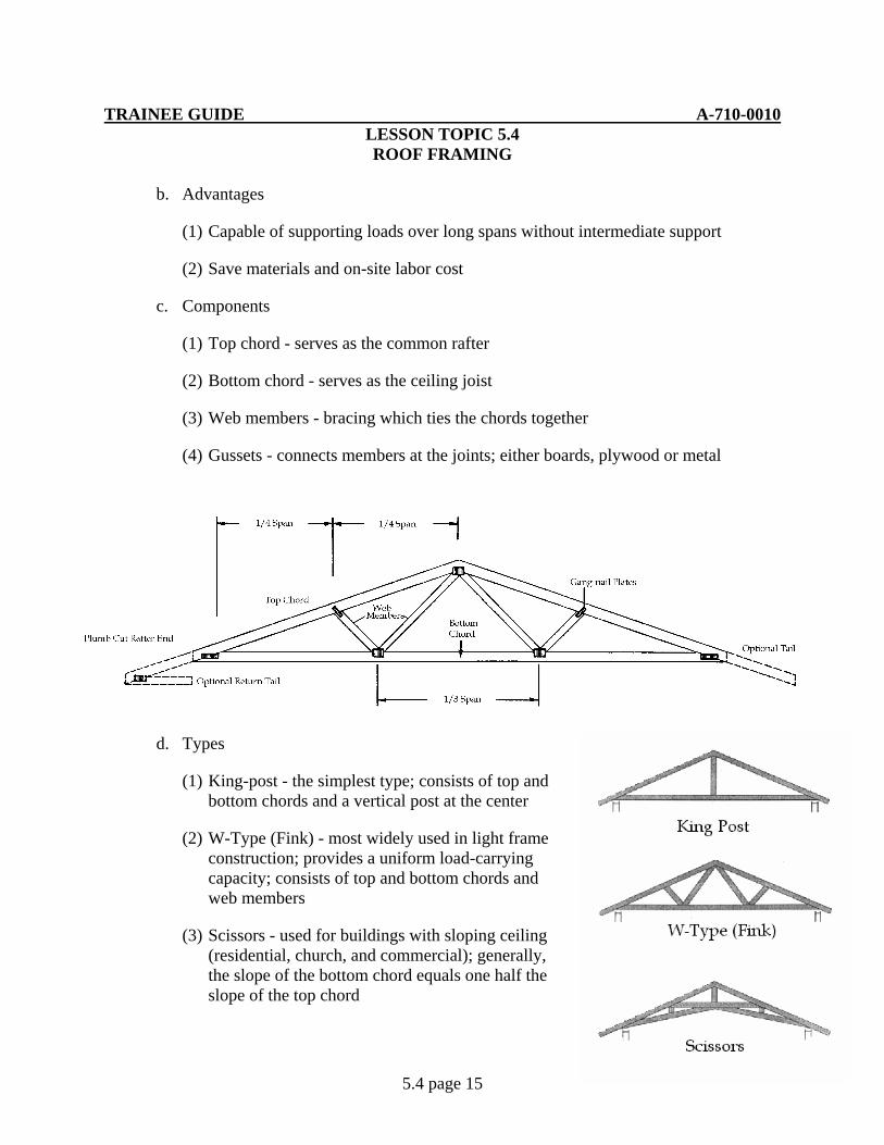
TRAINEE GUIDE A-710-0010 LESSON TOPIC 5.4 ROOF FRAMING
5.4 page 15
b. Advantages
(1) Capable of supporting loads over long spans without intermediate support
(2) Save materials and on-site labor cost
c. Components
(1) Top chord - serves as the common rafter
(2) Bottom chord - serves as the ceiling joist
(3) Web members - bracing which ties the chords together
(4) Gussets - connects members at the joints; either boards, plywood or metal
d. Types
(1) King-post - the simplest type; consists of top and bottom chords and a vertical post at the center
(2) W-Type (Fink) - most widely used in light frame construction; provides a uniform load-carrying capacity; consists of top and bottom chords and web members
(3) Scissors - used for buildings with sloping ceiling (residential, church, and commercial); generally, the slope of the bottom chord equals one half the slope of the top chord
TRAINEE GUIDE A-710-0010 LESSON TOPIC 5.4 ROOF FRAMING
5.4 page 16
e. Fabrication
(1) Trusses can be easily pre-fabricated and then transported to the job site
(a) A pattern/template is made and used for assembly of the trusses
f. Installation
(1) Trusses are spaced 24" O. C.
(2) Position first truss; fasten to double top plate with metal anchor brackets or by toe nail into position. Next fasten 2” by 4” braces from the truss to stakes at ground level ensuring that the truss is plumb. This will only work on s single story building.
(3) Position remaining trusses at specific intervals and tie into previous truss utilizing lateral bracing (1” x4” or 2” x 4” material)
(4) As roof sheathing is installed, the lateral bracing is removed
g. Repair/replace roof truss
(1) Type of damage must first be determined prior to any repairs.
(a) Insect infestation such as termite or wood ants may require treatment prior to repairs.
(b) Structural damage may occur naturally or be caused by human factors.
(2) Bottom chord that is cracked/broken can be jacked into place leaving existing covering in place. Lumber of the same size can be installed next to the existing bottom cord. This process is known as scabbing
(3) If the bottom chord must be replaced due to excessive damage, the interior covering must be removed. Once covering is removed, damaged chord or member should be replaced. While removing chord additional support maybe needed. Install new member and secure. New gusset plates will be required to reinforce the new bottom chord. Replace covering to match existing.
(4) If the top chord must be replaced due to excessive damage, the exterior covering must be removed. Once covering is removed, damaged member should be replaced. While removing chord additional support maybe needed. Install new member and secure. New gusset plates will be required to reinforce the new top cord. Replace covering to match existing.
TRAINEE GUIDE A-710-0010 LESSON TOPIC 5.4 ROOF FRAMING
5.4 page 17
(5) Top chord that is cracked/broken can be jacked into place leaving existing covering in place. Lumber of the same size can be installed next to the existing broken chord. This process is known as scabbing
TRAINEE GUIDE A-710-0010 LESSON TOPIC 5.4 ROOF FRAMING
5.4 page 18
JOB SHEET 5.4-1
A. This job sheet will provide the information needed for you to construct a roof frame
consisting of ceiling joist, collar ties, rafters, ridge board and gable end studs
B. Equipment required
a. 16’ tape measure
b. Framing square
c. Speed square
d. Crosscut hand saw
e. Circular saw
f. Extension cord
g. 22 oz. Framing hammer
h. Saw horses
i. 1” x 6” lumber
j. 2” x 4” lumber
k. 2” x 6” lumber
l. 8d nails
m. 16d nails
C. Reference:
1. Builder 3&2 Vol.2 NAVEDTRA 12521
2. Carpentry 3rd Edition, Delmar
D. Job steps:
Note: Refer to diagram sheet and Details on blue prints A-5 Roofing detail as necessary when performing the following tasks
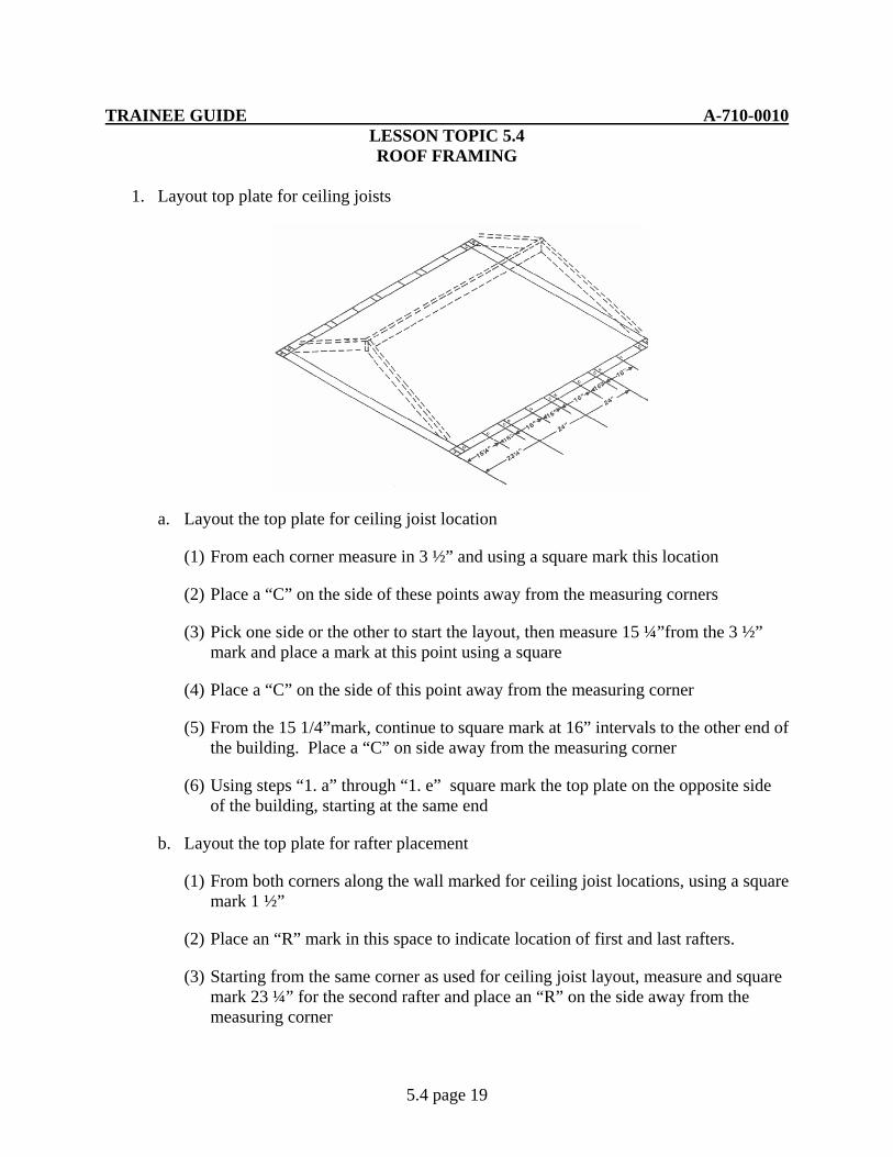
TRAINEE GUIDE A-710-0010 LESSON TOPIC 5.4 ROOF FRAMING
5.4 page 19
1. Layout top plate for ceiling joists
a. Layout the top plate for ceiling joist location
(1) From each corner measure in 3 ½” and using a square mark this location
(2) Place a “C” on the side of these points away from the measuring corners
(3) Pick one side or the other to start the layout, then measure 15 ¼”from the 3 ½” mark and place a mark at this point using a square
(4) Place a “C” on the side of this point away from the measuring corner
(5) From the 15 1/4”mark, continue to square mark at 16” intervals to the other end of the building. Place a “C” on side away from the measuring corner
(6) Using steps “1. a” through “1. e” square mark the top plate on the opposite side of the building, starting at the same end
b. Layout the top plate for rafter placement
(1) From both corners along the wall marked for ceiling joist locations, using a square mark 1 ½”
(2) Place an “R” mark in this space to indicate location of first and last rafters.
(3) Starting from the same corner as used for ceiling joist layout, measure and square mark 23 ¼” for the second rafter and place an “R” on the side away from the measuring corner
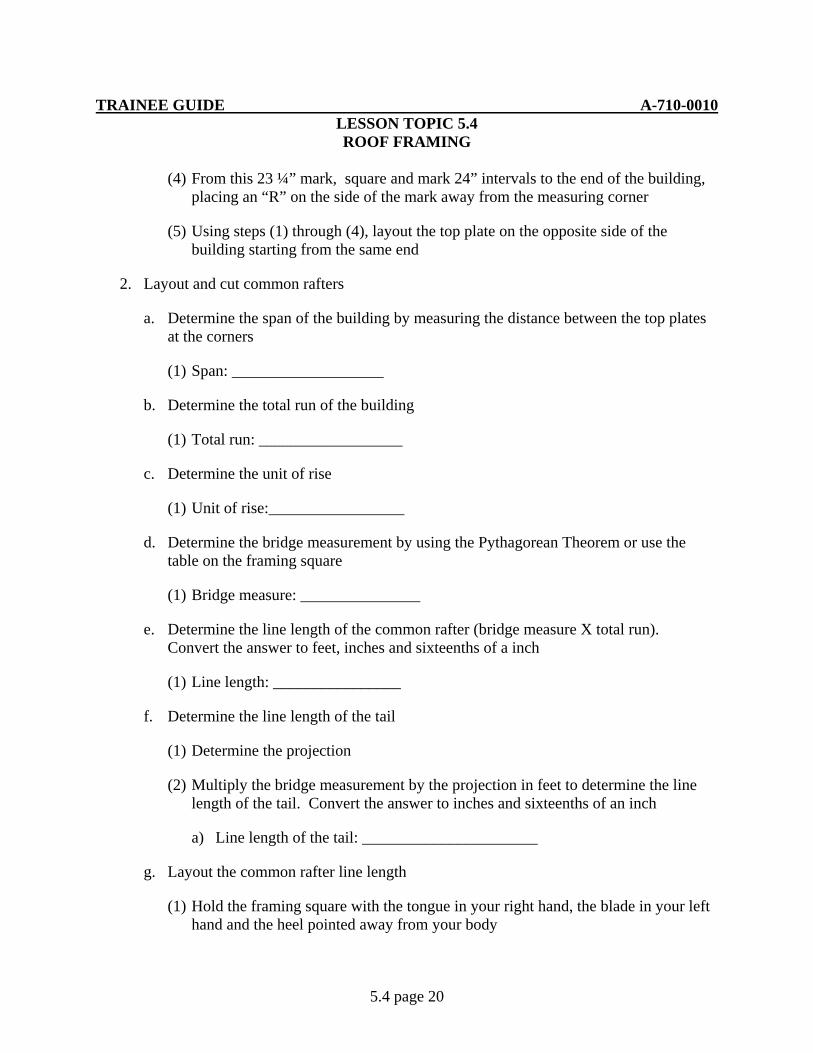
TRAINEE GUIDE A-710-0010 LESSON TOPIC 5.4 ROOF FRAMING
5.4 page 20
(4) From this 23 ¼” mark, square and mark 24” intervals to the end of the building, placing an “R” on the side of the mark away from the measuring corner
(5) Using steps (1) through (4), layout the top plate on the opposite side of the building starting from the same end
2. Layout and cut common rafters
a. Determine the span of the building by measuring the distance between the top plates at the corners
(1) Span: ___________________
b. Determine the total run of the building
(1) Total run: __________________
c. Determine the unit of rise
(1) Unit of rise:_________________
d. Determine the bridge measurement by using the Pythagorean Theorem or use the table on the framing square
(1) Bridge measure: _______________
e. Determine the line length of the common rafter (bridge measure X total run). Convert the answer to feet, inches and sixteenths of a inch
(1) Line length: ________________
f. Determine the line length of the tail
(1) Determine the projection
(2) Multiply the bridge measurement by the projection in feet to determine the line length of the tail. Convert the answer to inches and sixteenths of an inch
a) Line length of the tail: ______________________
g. Layout the common rafter line length
(1) Hold the framing square with the tongue in your right hand, the blade in your left hand and the heel pointed away from your body
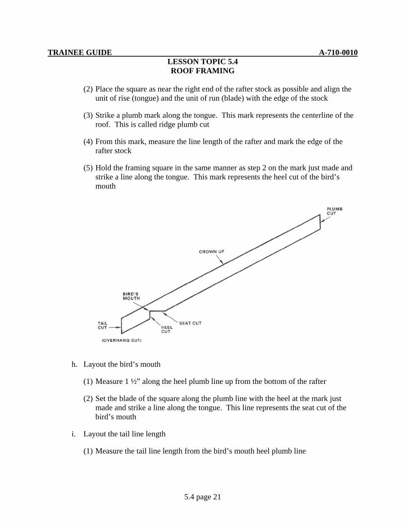
TRAINEE GUIDE A-710-0010 LESSON TOPIC 5.4 ROOF FRAMING
5.4 page 21
(2) Place the square as near the right end of the rafter stock as possible and align the unit of rise (tongue) and the unit of run (blade) with the edge of the stock
(3) Strike a plumb mark along the tongue. This mark represents the centerline of the roof. This is called ridge plumb cut
(4) From this mark, measure the line length of the rafter and mark the edge of the rafter stock
(5) Hold the framing square in the same manner as step 2 on the mark just made and strike a line along the tongue. This mark represents the heel cut of the bird’s mouth
h. Layout the bird’s mouth
(1) Measure 1 ½” along the heel plumb line up from the bottom of the rafter
(2) Set the blade of the square along the plumb line with the heel at the mark just made and strike a line along the tongue. This line represents the seat cut of the bird’s mouth
i. Layout the tail line length
(1) Measure the tail line length from the bird’s mouth heel plumb line
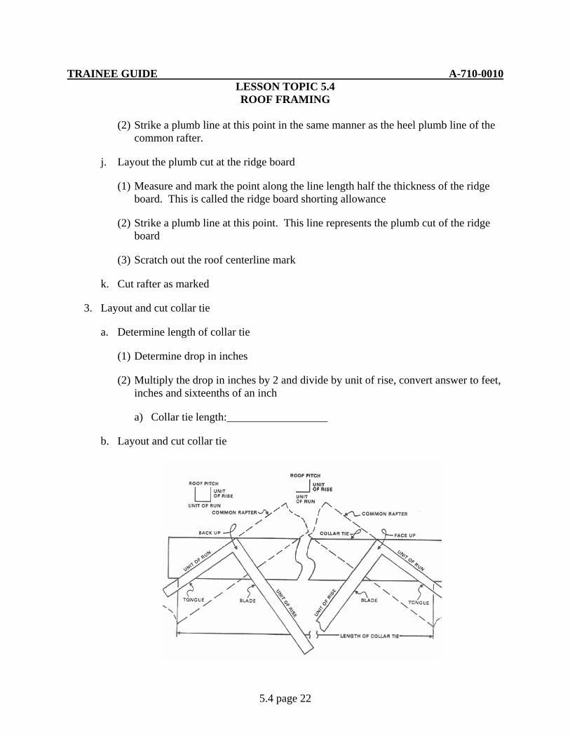
TRAINEE GUIDE A-710-0010 LESSON TOPIC 5.4 ROOF FRAMING
5.4 page 22
(2) Strike a plumb line at this point in the same manner as the heel plumb line of the common rafter.
j. Layout the plumb cut at the ridge board
(1) Measure and mark the point along the line length half the thickness of the ridge board. This is called the ridge board shorting allowance
(2) Strike a plumb line at this point. This line represents the plumb cut of the ridge board
(3) Scratch out the roof centerline mark
k. Cut rafter as marked
3. Layout and cut collar tie
a. Determine length of collar tie
(1) Determine drop in inches
(2) Multiply the drop in inches by 2 and divide by unit of rise, convert answer to feet, inches and sixteenths of an inch
a) Collar tie length:__________________
b. Layout and cut collar tie

TRAINEE GUIDE A-710-0010 LESSON TOPIC 5.4 ROOF FRAMING
5.4 page 23
(1) Using 1” x 6” lumber, hold the framing square with the unit of rise on the tongue and the unit of run on the blade as near the right end of the board as possible
(2) Strike a line along the blade
(3) Mark off the line length from the mark at the bottom of the board to the left
(4) Reverse the framing square with the blade on the left and tongue on the right
(5) Hold the blade with the unit of run at the marked line length and the tongue with the unit on rise along the edge and strike a line along the blade
(6) Cut the collar tie as marked
4. Prepare the ceiling joists
a. Square cut the ceiling joist to the required length
b. With the crown of the joist up, use a framing square to mark off the slope of the roof
(1) Measure the distance above the bird’s mouth along the heel plumb line
(2) From the bottom of the joist end, measure and mark the amount found in step 1
(3) Hold the unit of run on the blade and the unit of rise on the tongue, make sure the heel is pointed away from you. Mark the cutoff line on the unit of run side from this point
(4) Using steps b.1 through b.3 mark the opposite end of the joist
c. Cut both ends of the joist
d. Secure the ceiling joist
(1) Align a joist over the first “C” marks at each end of the top plates
(2) Toenail each end of every joist to the top plate with at least two 16d duplex nails
5. Erecting the roof frame
a. Layout and cut the ridge board
(1) Length of material should be as long as the roof plus the overhang that is required on each end
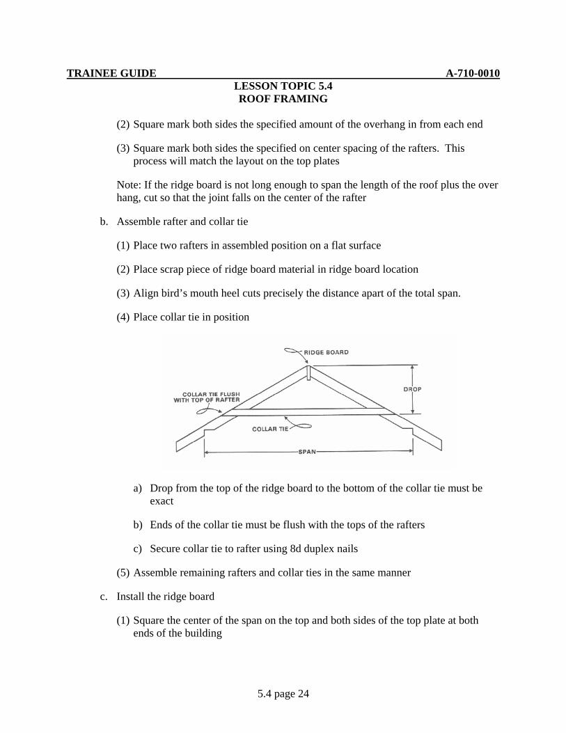
TRAINEE GUIDE A-710-0010 LESSON TOPIC 5.4 ROOF FRAMING
5.4 page 24
(2) Square mark both sides the specified amount of the overhang in from each end
(3) Square mark both sides the specified on center spacing of the rafters. This process will match the layout on the top plates
Note: If the ridge board is not long enough to span the length of the roof plus the over hang, cut so that the joint falls on the center of the rafter
b. Assemble rafter and collar tie
(1) Place two rafters in assembled position on a flat surface
(2) Place scrap piece of ridge board material in ridge board location
(3) Align bird’s mouth heel cuts precisely the distance apart of the total span.
(4) Place collar tie in position
a) Drop from the top of the ridge board to the bottom of the collar tie must be exact
b) Ends of the collar tie must be flush with the tops of the rafters
c) Secure collar tie to rafter using 8d duplex nails
(5) Assemble remaining rafters and collar ties in the same manner
c. Install the ridge board
(1) Square the center of the span on the top and both sides of the top plate at both ends of the building

TRAINEE GUIDE A-710-0010 LESSON TOPIC 5.4 ROOF FRAMING
5.4 page 25
(2) Square mark half the thickness of the ridge board to the right and left of these center marks
(3) Determine the height of the ridge board above the top plate, convert answer to feet, inches and sixteenths of an inch
a) Height of the ridge board: ____________________
(4) Layout and install temporary ridge board supports
a) Square mark one end of a selected 2” x 4”
b) Square mark the width of the ridge board below this mark.
c) From the first mark, measure down the height of ridge board above the top plate and square mark this point
d) On the outside of the wall, align the edge of the 2” x 4” at this last square mark with the square mark on the top plate that is offset half the thickness of the ridge board
e) Plumb and nail the 2” x 4” to the side of the building
f) Align the bottom of the ridge board with the second square mark on the temporary support, extending the ridge board beyond the support
g) Secure the ridge board to the temporary supports
d. Install rafters and collar ties
(1) Align the first set of rafters and collar tie with the placement marks on the top plate and ridge board
a) Be certain that the bird’s mouth is seated properly on the top plates
(2) Secure rafter to the top plate and ridge board
(3) Install remaining rafters and collar ties in the same manner
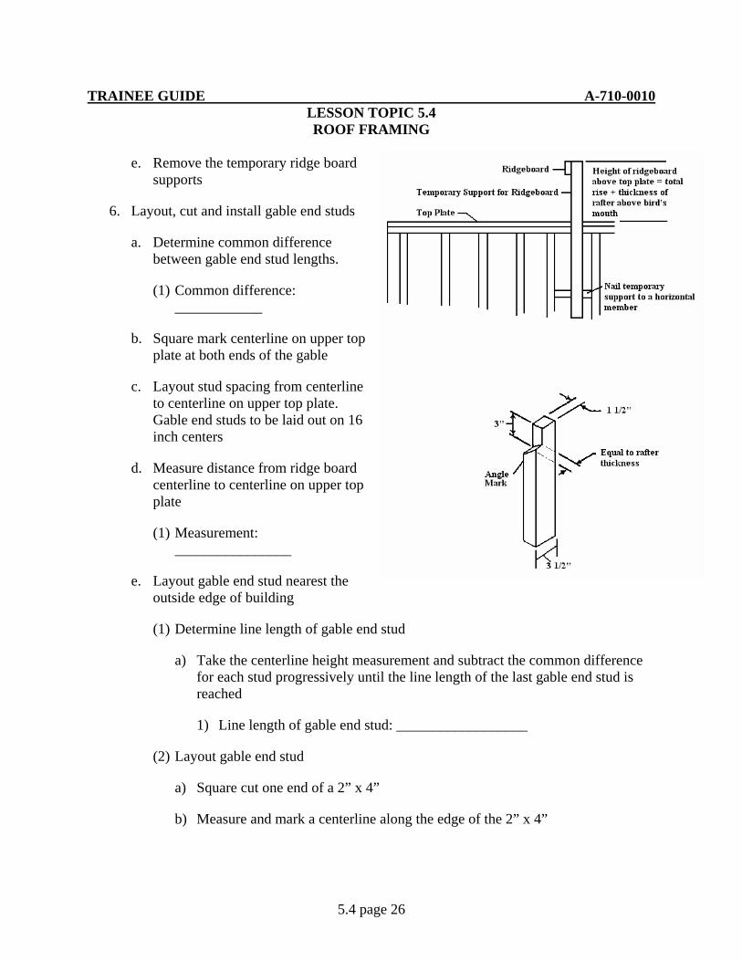
TRAINEE GUIDE A-710-0010 LESSON TOPIC 5.4 ROOF FRAMING
5.4 page 26
e. Remove the temporary ridge board supports
6. Layout, cut and install gable end studs
a. Determine common difference between gable end stud lengths.
(1) Common difference: ____________
b. Square mark centerline on upper top plate at both ends of the gable
c. Layout stud spacing from centerline to centerline on upper top plate. Gable end studs to be laid out on 16 inch centers
d. Measure distance from ridge board centerline to centerline on upper top plate
(1) Measurement: ________________
e. Layout gable end stud nearest the outside edge of building
(1) Determine line length of gable end stud
a) Take the centerline height measurement and subtract the common difference for each stud progressively until the line length of the last gable end stud is reached
1) Line length of gable end stud: __________________
(2) Layout gable end stud
a) Square cut one end of a 2” x 4”
b) Measure and mark a centerline along the edge of the 2” x 4”
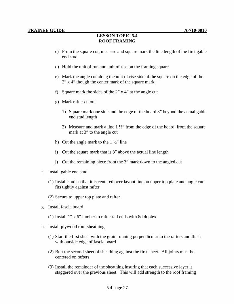
TRAINEE GUIDE A-710-0010 LESSON TOPIC 5.4 ROOF FRAMING
5.4 page 27
c) From the square cut, measure and square mark the line length of the first gable end stud
d) Hold the unit of run and unit of rise on the framing square
e) Mark the angle cut along the unit of rise side of the square on the edge of the 2” x 4” though the center mark of the square mark.
f) Square mark the sides of the 2” x 4” at the angle cut
g) Mark rafter cutout
1) Square mark one side and the edge of the board 3” beyond the actual gable end stud length
2) Measure and mark a line 1 ½” from the edge of the board, from the square mark at 3” to the angle cut
h) Cut the angle mark to the 1 ½” line
i) Cut the square mark that is 3” above the actual line length
j) Cut the remaining piece from the 3” mark down to the angled cut
f. Install gable end stud
(1) Install stud so that it is centered over layout line on upper top plate and angle cut fits tightly against rafter
(2) Secure to upper top plate and rafter
g. Install fascia board
(1) Install 1” x 6” lumber to rafter tail ends with 8d duplex
h. Install plywood roof sheathing
(1) Start the first sheet with the grain running perpendicular to the rafters and flush with outside edge of fascia board
(2) Butt the second sheet of sheathing against the first sheet. All joints must be centered on rafters
(3) Install the remainder of the sheathing insuring that each successive layer is staggered over the previous sheet. This will add strength to the roof framing

TRAINEE GUIDE A-710-0010 LESSON TOPIC 6.1 EXTERIOR FINISH
6.1 page 1
A. Introduction
During this lesson you will learn how to install and repair various types of exterior wall covering.
B. Enabling Objectives
13.1 IDENTIFY exterior finishes, trim, installation and repair/replacement procedures in accordance with Builder 3&2 Vol.2 NAVEDTRA 12521 and Carpentry 3rd Edition, Delmar
13.2 APPLY vapor barrier to exterior sheathing in accordance with Builder 3&2 Vol.2 NAVEDTRA 12521 and Carpentry 3rd Edition, Delmar
13.3 INSTALL corner board ensuring it is plumb within +/- 1/8" in accordance with Builder 3&2 Vol.2 NAVEDTRA 12521 and Carpentry 3rd Edition, Delmar
13.4 INSTALL clapboard siding as specified in accordance with Builder 3&2 Vol.2 NAVEDTRA 12521 and Carpentry 3rd Edition, Delmar
13.5 OBSERVE all safety precautions during exterior finish operations in accordance with applicable instructions
C. Topic Outline
1. Introduction
2. Exterior Wall Finish
a. Definition – Exterior wall covering protects structure from the elements. The exterior finish also affects the appearance and maintenance.
b. Types - wood shingles, plywood, wood siding (paneling), fiberboard, hardboard, masonry, stucco, metal or vinyl siding
(1) The type of exterior finish is dictated by location, styles of the time and economics.
(2) Often wood and masonry materials are combined for the exterior wall finish of a building
c. Siding

TRAINEE GUIDE A-710-0010 LESSON TOPIC 6.1 EXTERIOR FINISH
6.1 page 2
(1) Can be installed over some type of panel sheathing and building paper (if required). In mild climates, exterior finish may be installed directly over the studs.
(a) Vapor barrier is used to control the transfer of moisture from the exterior to the interior walls
1) Building paper, roofing felt paper and breathable type polyethylene films are examples of vapor barrier, and may also be know as “House wrap”.
(b) When installed over solid sheathing, the siding may be nailed directly to the sheathing and end joints may fall between framing members (studs).
(2) Horizontal siding - constructed of horizontal overlapping strips of wood, aluminum, or vinyl.
(a) Common types of wood horizontal siding:
1) Clapboard
2) Bevel siding
3) Rabbeted bevel siding
4) Rustic siding
5) Drop siding
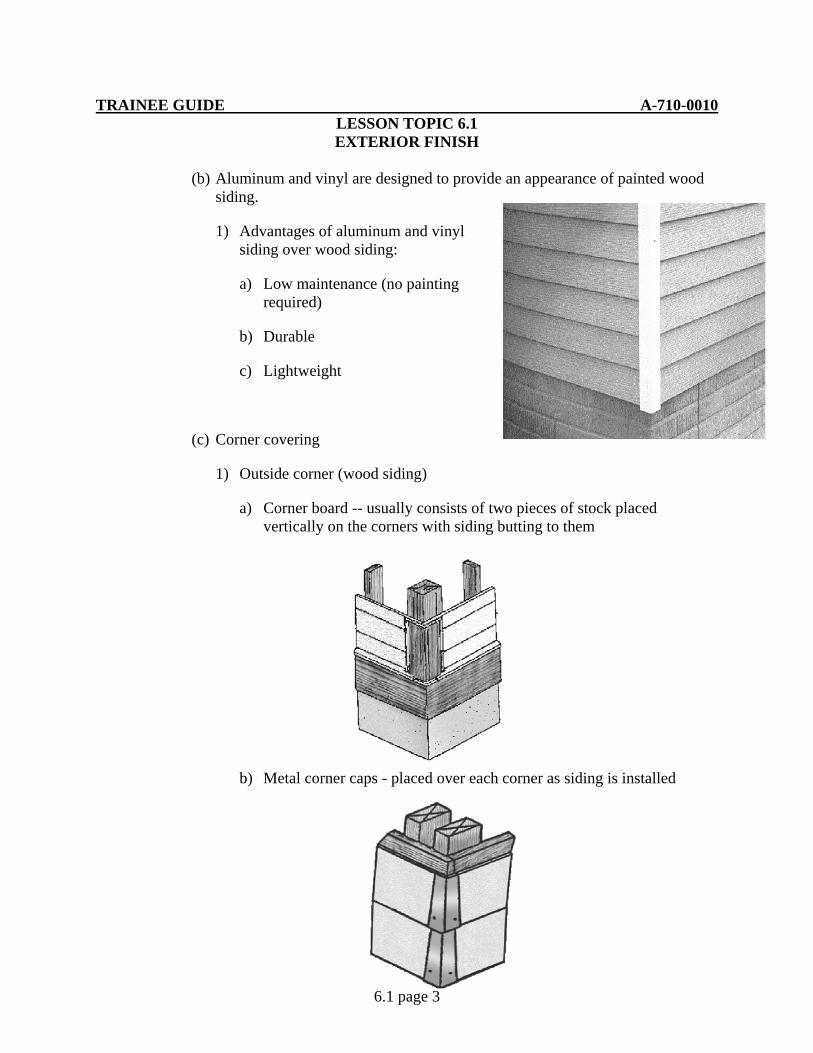
TRAINEE GUIDE A-710-0010 LESSON TOPIC 6.1 EXTERIOR FINISH
6.1 page 3
(b) Aluminum and vinyl are designed to provide an appearance of painted wood siding.
1) Advantages of aluminum and vinyl siding over wood siding:
a) Low maintenance (no painting required)
b) Durable
c) Lightweight
(c) Corner covering
1) Outside corner (wood siding)
a) Corner board -- usually consists of two pieces of stock placed vertically on the corners with siding butting to them
b) Metal corner caps - placed over each corner as siding is installed

TRAINEE GUIDE A-710-0010 LESSON TOPIC 6.1 EXTERIOR FINISH
6.1 page 4
c) Mitered - not always satisfactory unless it is carefully done to prevent overlapping
2) Inside corners (wood siding)
a) Corner strip - a square strip fastened to the inside corner with siding butting to it
b) Mitered - not always satisfactory unless it is carefully done to prevent overlapping

TRAINEE GUIDE A-710-0010 LESSON TOPIC 6.1 EXTERIOR FINISH
6.1 page 5
3) Aluminum and vinyl - siding manufacturers offer special corners and trim accessories made to use with their siding systems. Accessories may different from one brand to another.
(3) Vertical siding - commonly used to set off entrances and/or gable ends, may also be used for main wall areas
(a) Wood types
1) Board and batten - wide boards are attached vertically with small gaps between and covered with wooden batten strips. Plywood attached vertically with wood strips nailed at regular intervals to give appearance of board and batten.
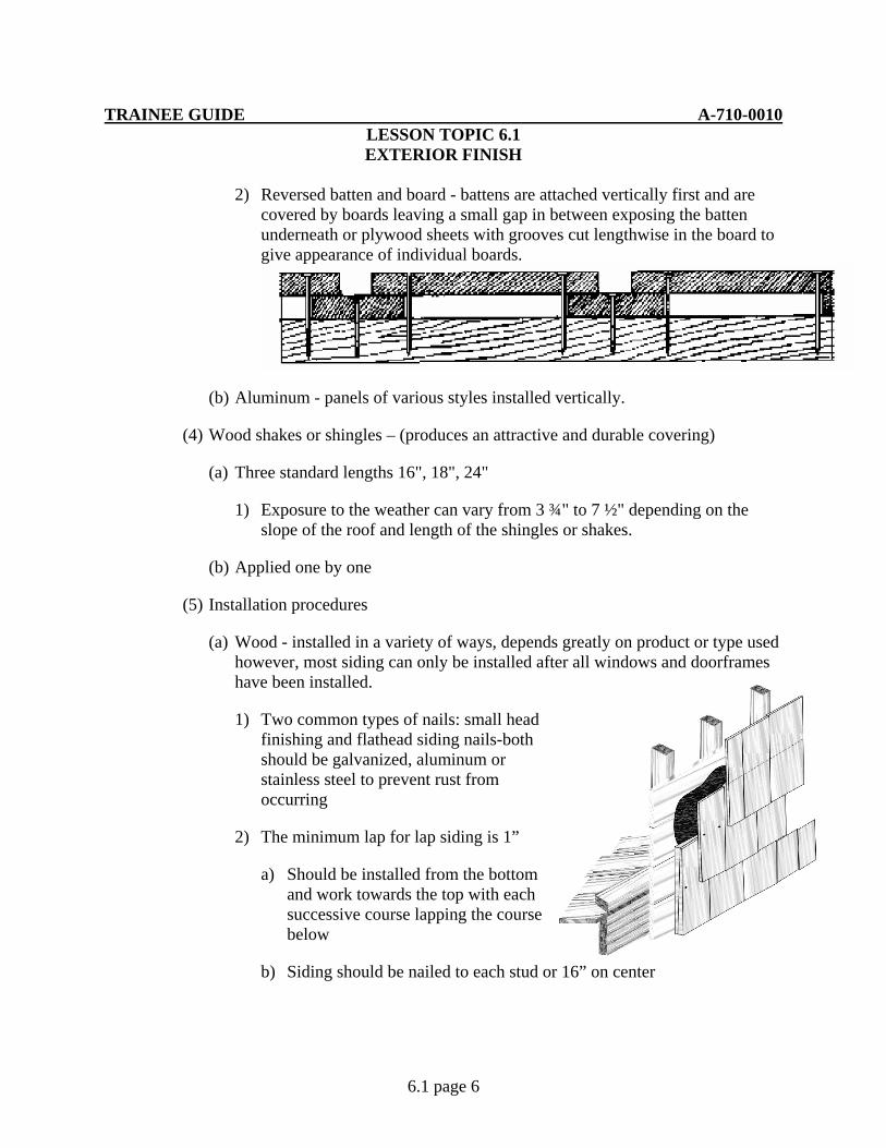
TRAINEE GUIDE A-710-0010 LESSON TOPIC 6.1 EXTERIOR FINISH
6.1 page 6
2) Reversed batten and board - battens are attached vertically first and are covered by boards leaving a small gap in between exposing the batten underneath or plywood sheets with grooves cut lengthwise in the board to give appearance of individual boards.
(b) Aluminum - panels of various styles installed vertically.
(4) Wood shakes or shingles – (produces an attractive and durable covering)
(a) Three standard lengths 16", 18", 24"
1) Exposure to the weather can vary from 3 ¾" to 7 ½" depending on the slope of the roof and length of the shingles or shakes.
(b) Applied one by one
(5) Installation procedures
(a) Wood - installed in a variety of ways, depends greatly on product or type used however, most siding can only be installed after all windows and doorframes have been installed.
1) Two common types of nails: small head finishing and flathead siding nails-both should be galvanized, aluminum or stainless steel to prevent rust from occurring
2) The minimum lap for lap siding is 1”
a) Should be installed from the bottom and work towards the top with each successive course lapping the course below
b) Siding should be nailed to each stud or 16” on center

TRAINEE GUIDE A-710-0010 LESSON TOPIC 6.1 EXTERIOR FINISH
6.1 page 7
3) Consult drawing and specifications on type and method of application for various types of wood siding
(b) Aluminum and vinyl - follow manufacturer's instructions for the specific siding being used, but in general the following procedures apply:
1) Install a starter strip around the entire bottom edge of the building
2) Install corner posts ensuring they are at least ¼” below the starter strip and ¼” from the top of the wall
3) Install “J” – channel across top, bottom and sides of windows and door casings
4) Install siding panel beginning at the bottom by snapping them into the starter strip and fastening them at the top. All successive courses course interlock with the course below and should be staggered
(6) Repair/replacement of wood siding
(a) When replacing wooden siding, type and style must be taken into consideration prior to removal.
1) When replacing lap type siding (bevel, rabbeted, lap) remove nails from piece of siding above damaged siding. Remove nails from damaged

TRAINEE GUIDE A-710-0010 LESSON TOPIC 6.1 EXTERIOR FINISH
6.1 page 8
siding and install new piece of siding. Nail new siding in place and secure existing siding.
2) Vertical siding (board & batten, plywood panels) remove nails from damaged member. Replace entire damaged member with same size and type. Fasten as required by original installation.
3) Overlapping/tongue and groove siding (shingles, shakes, drop siding) Siding that has multiple layers or tongue and groove must be removed starting at the last layer or member installed and removed down to the damaged area and reinstalled.
(7) Exterior ventilation – condensation of moisture may occur in attics during cold weather. Adequate roof ventilation will help remove the moisture
(a) Types
1) Louvers – installed in the ends of gable openings. Air movement is based upon the amount of wind flow. Works well in conjunction with soffit vents. The siding is cut to go around the louver vent
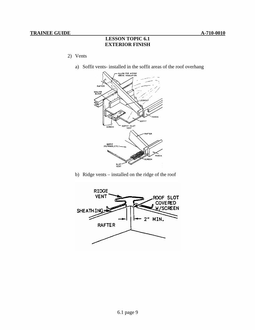
TRAINEE GUIDE A-710-0010 LESSON TOPIC 6.1 EXTERIOR FINISH
6.1 page 9
2) Vents
a) Soffit vents- installed in the soffit areas of the roof overhang
b) Ridge vents – installed on the ridge of the roof

TRAINEE GUIDE A-710-0010 LESSON TOPIC 6.1 EXTERIOR FINISH
6.1 page 10
c) Turbine ventilators – installed on the roof. As the wind blows, the ventilator rotates drawing the attic air from inside the roof. Works in conjunction with soffit or cornice vents
TRAINEE GUIDE A-710-0010 LESSON TOPIC 6.1 EXTERIOR FINISH
6.1 page 11
JOB SHEET 6.1-1
A. This job sheet will provide the information needed for you to install exterior siding
B. Equipment required
1. 16’ tape measure
2. Framing square
3. Speed square
4. Cross cut hand saw
5. Circular saw
6. Extension cord
7. Saw horses
8. 22 oz. Framing hammer
9. 1” x 6” lumber
10. 2” x 4” lumber
11. Lapboard siding
12. 8d nails
13. 16d nails
14. 15 lb. felt paper
15. Utility knife
C. References:
1. Builder 3&2 Vol.2 NAVEDTRA 12521
2. Carpentry 3rd Edition, Delmar
TRAINEE GUIDE A-710-0010 LESSON TOPIC 6.1 EXTERIOR FINISH
6.1 page 12
D. Job steps:
1. Install felt paper
a. Cut in to 6’ lengths
b. Align felt paper vertically along plywood sheathing at the corner leaving a 6” overhang at the corner
c. Staple felt paper to plywood at approximately 2’ intervals vertically and 12” to 16” on center horizontally
2. Install corner board
a. Cut corner board material 6’ in length
b. Install flush along outside of building corner with 16d common nails for 2x material and 8d common for 1x material. Nail spacing is approximately 12” to 18” on center
3. Install ledger board/ starter strip
a. Nail board/strip flush along bottom of sheathing with 8d common nails, 12” on center
4. Install siding
a. Lap siding
(1) Cut siding into 32” lengths. Six pieces will be required for the project
(2) Start from bottom of the ledger board, measure, mark, and snap chalk lines at intervals the width of the siding minus 1” for the overlap
Example: using 8” wide lapboard, mark at 7” intervals
(3) Install first course
a) Nail board with upper edge on board flush with the first guideline, placing 8d common nails just above the 1” overlap up from the bottom edge spacing nails approximately 16” on center or to each stud
NOTE: 8d common nails used for TRAINING PURPOSES ONLY. Siding nails are used for real application
(4) Follow procedures in 3.a for successive courses

TRAINEE GUIDE A-710-0010 LESSON TOPIC 6.1 EXTERIOR FINISH
6.1 page 13
TRAINEE GUIDE A-710-0010 LESSON TOPIC 6.2
COMPOSITION SHINGLES
6.2 page 1
A. Introduction
During this lesson you learn how to estimate, install and repair composition shingles.
B. Enabling Objectives
14.1 STRIP existing shingles in accordance with Builder 3&2 Vol.2 NAVEDTRA 12521 and Carpentry 3rd Edition, Delmar
14.2 APPLY felt underlayment in accordance with Builder 3&2 Vol.2 NAVEDTRA 12521 and Carpentry 3rd Edition, Delmar
14.3 INSTALL drip edge on roof perimeter in accordance with Builder 3&2 Vol.2 NAVEDTRA 12521 and Carpentry 3rd Edition, Delmar.
14.4 LAYOUT guidelines as specified in accordance with Builder 3&2 Vol.2 NAVEDTRA 12521 and Carpentry 3rd Edition, Delmar
14.5 APPLY shingles per specifications in accordance with Builder 3&2 Vol.2 NAVEDTRA 12521 and Carpentry 3rd Edition, Delmar
14.6 DESCRIBE the installation and repair of composition shingles, roll and metal roofing in accordance with Builder 3 & 2 Vol. 2 NAVEDTRA12521, Structural Journeyman Vol.1, CDC 3E351C and Carpentry 3rd Edition, Delamr
14.7 OBSERVE all safety precautions during composition shingles operations in accordance with applicable instructions
C. Topic Outline
1. Introduction
2. Introduction to Shingles
a. General Information
(1) Of all roofing material, asphalt shingles are the most widely used. There are two basic types that are manufactured, fiberglass and organic
(a) Organic shingles – made by saturating a heavy asphalt paper with additional asphalt and surfacing with a protective layer of mineral granules. Provides a Class C fire resistance rating that meets most fire codes
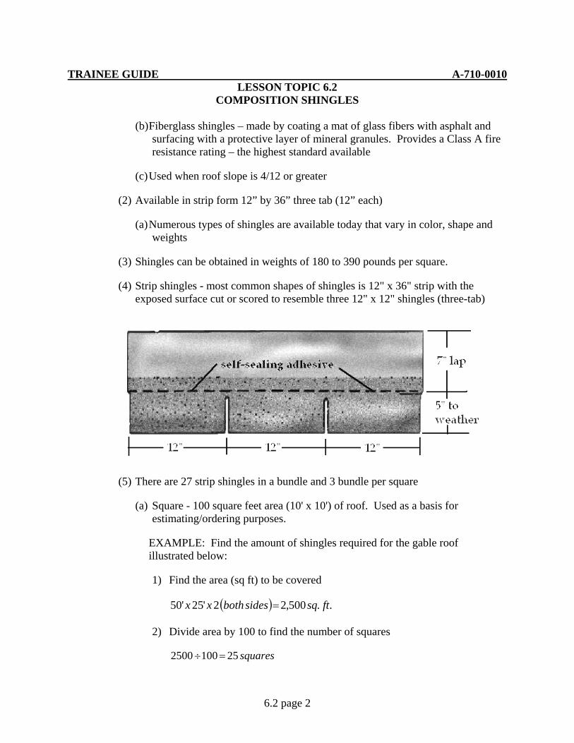
TRAINEE GUIDE A-710-0010 LESSON TOPIC 6.2
COMPOSITION SHINGLES
6.2 page 2
(b) Fiberglass shingles – made by coating a mat of glass fibers with asphalt and surfacing with a protective layer of mineral granules. Provides a Class A fire resistance rating – the highest standard available
(c) Used when roof slope is 4/12 or greater
(2) Available in strip form 12” by 36” three tab (12” each)
(a) Numerous types of shingles are available today that vary in color, shape and weights
(3) Shingles can be obtained in weights of 180 to 390 pounds per square.
(4) Strip shingles - most common shapes of shingles is 12" x 36" strip with the exposed surface cut or scored to resemble three 12" x 12" shingles (three-tab)
(5) There are 27 strip shingles in a bundle and 3 bundle per square
(a) Square - 100 square feet area (10' x 10') of roof. Used as a basis for estimating/ordering purposes.
EXAMPLE: Find the amount of shingles required for the gable roof illustrated below:
1) Find the area (sq ft) to be covered
( ) ..500,22'25'50 ftsqsidesbothxx =
2) Divide area by 100 to find the number of squares
squares251002500 =÷
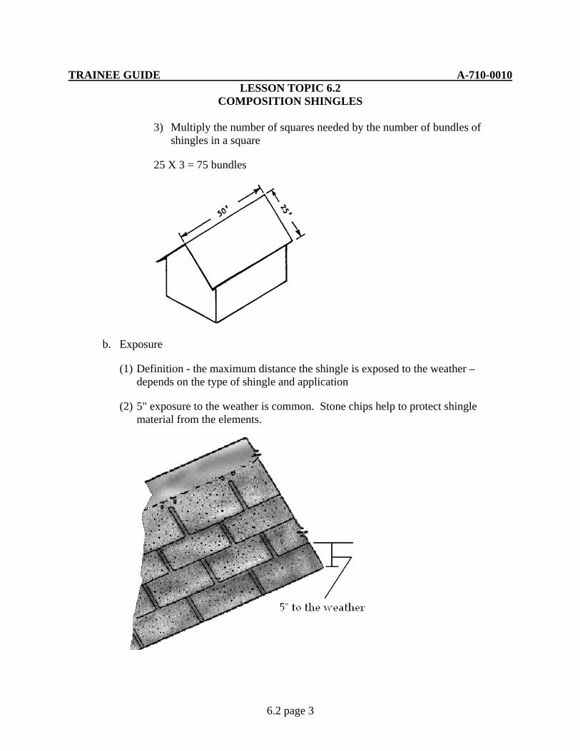
TRAINEE GUIDE A-710-0010 LESSON TOPIC 6.2
COMPOSITION SHINGLES
6.2 page 3
3) Multiply the number of squares needed by the number of bundles of shingles in a square
25 X 3 = 75 bundles
b. Exposure
(1) Definition - the maximum distance the shingle is exposed to the weather – depends on the type of shingle and application
(2) 5" exposure to the weather is common. Stone chips help to protect shingle material from the elements.

TRAINEE GUIDE A-710-0010 LESSON TOPIC 6.2
COMPOSITION SHINGLES
6.2 page 4
c. Top lap
(1) Definition - the distance a shingle overlaps the shingle directly below (7 inches).
d. Head lap
(1) Consists of a lap of 2 - 3 inches over the upper edge of the shingle in the second course below the shingle being installed
e. Fastening devices/methods
(1) Nails - must have a large head (3/8 to 7/16 inch diameter), and come in a variety of designs and lengths
(2) For three-tab strip shingles, use a minimum of 4 nails per strip, placed 3/4 to 1 inch above the cutouts, driven flush to the shingle. In some specifications may require 6 nails per strip
3. Application procedures
a. Roofing felt underlayment
(1) Purposes
(a) Keeps the roof sheathing dry until shingles can be applied
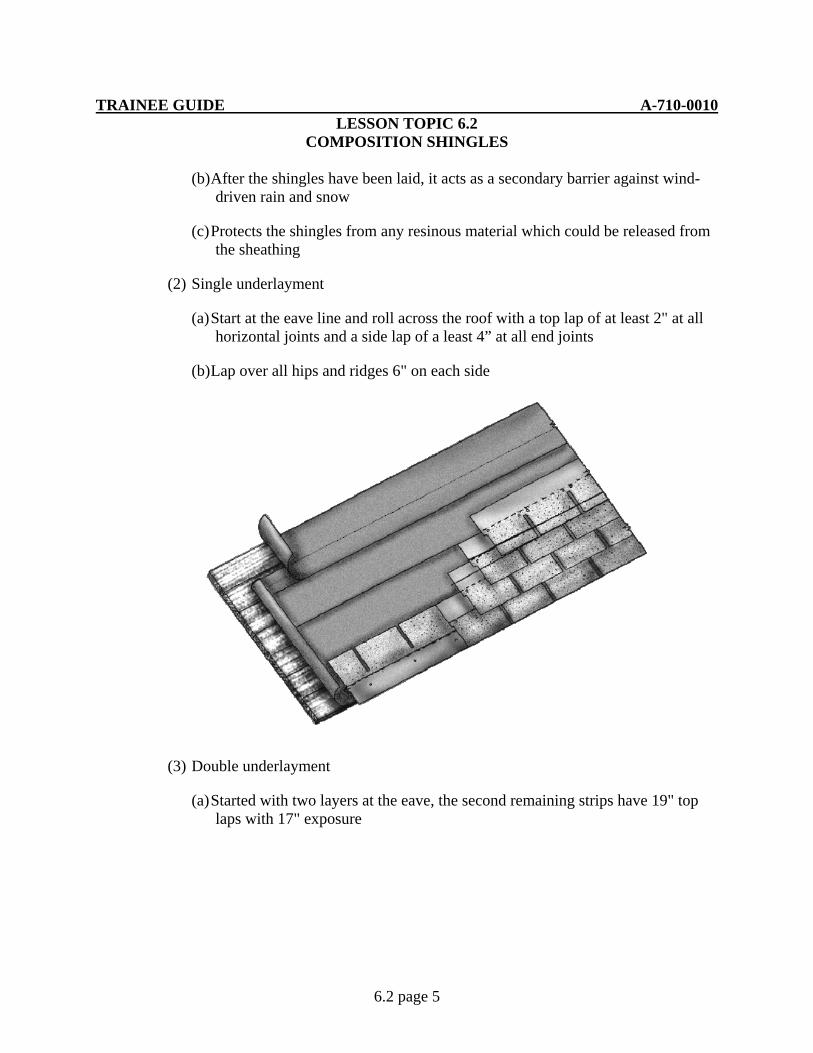
TRAINEE GUIDE A-710-0010 LESSON TOPIC 6.2
COMPOSITION SHINGLES
6.2 page 5
(b) After the shingles have been laid, it acts as a secondary barrier against wind-driven rain and snow
(c) Protects the shingles from any resinous material which could be released from the sheathing
(2) Single underlayment
(a) Start at the eave line and roll across the roof with a top lap of at least 2" at all horizontal joints and a side lap of a least 4” at all end joints
(b) Lap over all hips and ridges 6" on each side
(3) Double underlayment
(a) Started with two layers at the eave, the second remaining strips have 19" top laps with 17" exposure
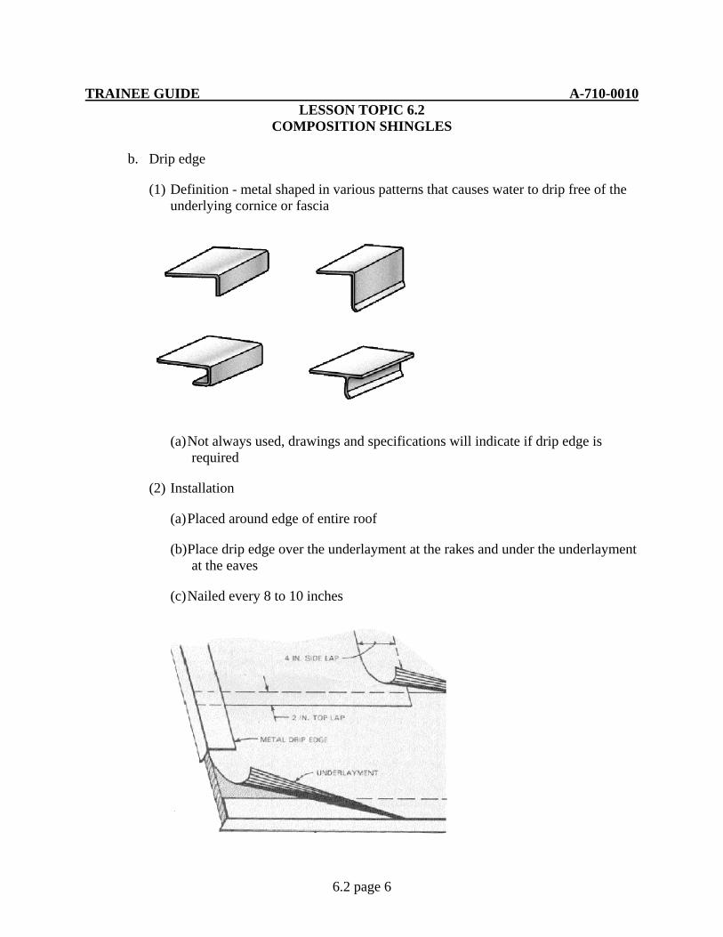
TRAINEE GUIDE A-710-0010 LESSON TOPIC 6.2
COMPOSITION SHINGLES
6.2 page 6
b. Drip edge
(1) Definition - metal shaped in various patterns that causes water to drip free of the underlying cornice or fascia
(a) Not always used, drawings and specifications will indicate if drip edge is required
(2) Installation
(a) Placed around edge of entire roof
(b) Place drip edge over the underlayment at the rakes and under the underlayment at the eaves
(c) Nailed every 8 to 10 inches
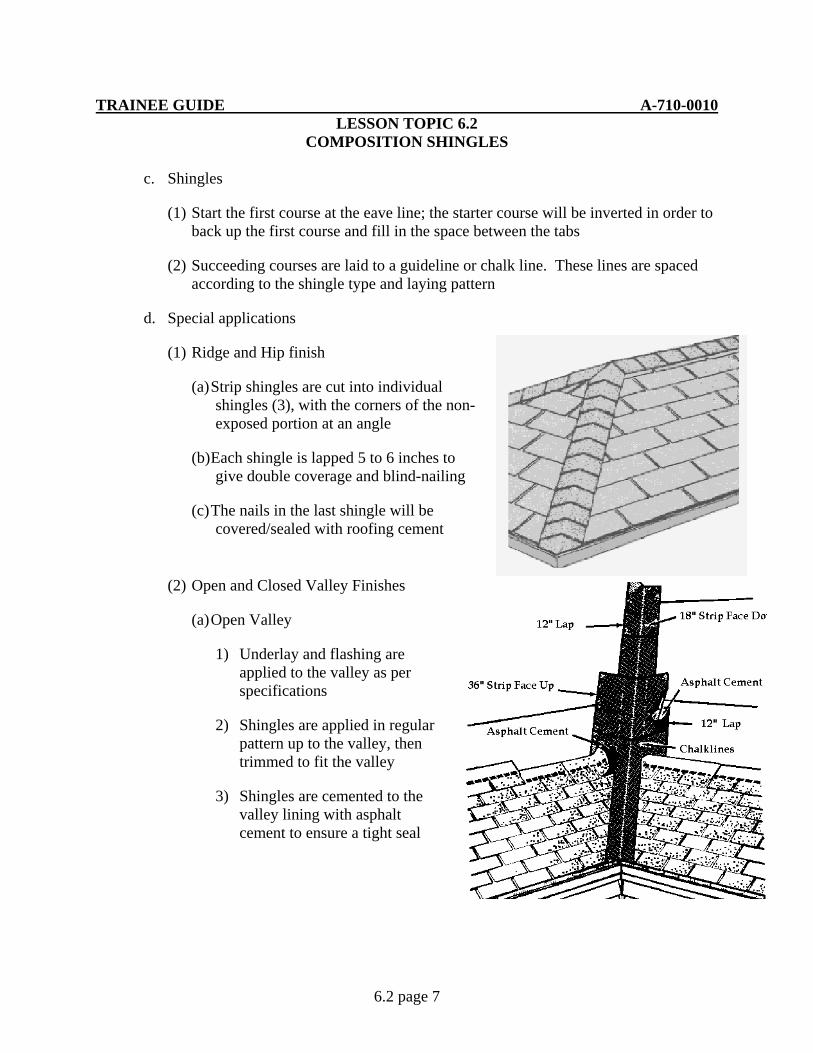
TRAINEE GUIDE A-710-0010 LESSON TOPIC 6.2
COMPOSITION SHINGLES
6.2 page 7
c. Shingles
(1) Start the first course at the eave line; the starter course will be inverted in order to back up the first course and fill in the space between the tabs
(2) Succeeding courses are laid to a guideline or chalk line. These lines are spaced according to the shingle type and laying pattern
d. Special applications
(1) Ridge and Hip finish
(a) Strip shingles are cut into individual shingles (3), with the corners of the non-exposed portion at an angle
(b) Each shingle is lapped 5 to 6 inches to give double coverage and blind-nailing
(c) The nails in the last shingle will be covered/sealed with roofing cement
(2) Open and Closed Valley Finishes
(a) Open Valley
1) Underlay and flashing are applied to the valley as per specifications
2) Shingles are applied in regular pattern up to the valley, then trimmed to fit the valley
3) Shingles are cemented to the valley lining with asphalt cement to ensure a tight seal
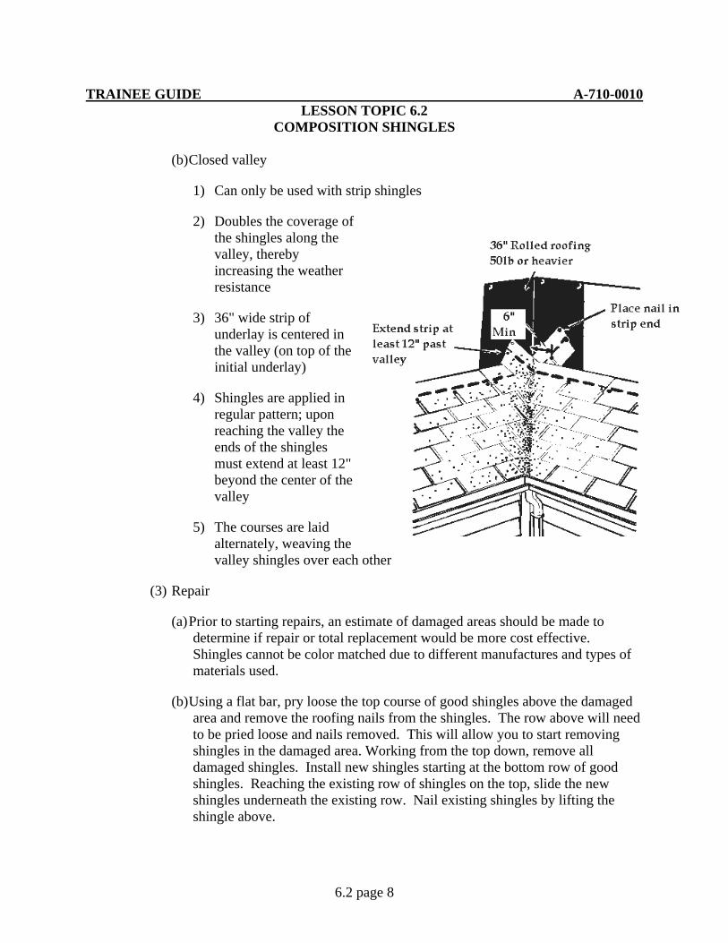
TRAINEE GUIDE A-710-0010 LESSON TOPIC 6.2
COMPOSITION SHINGLES
6.2 page 8
(b) Closed valley
1) Can only be used with strip shingles
2) Doubles the coverage of the shingles along the valley, thereby increasing the weather resistance
3) 36" wide strip of underlay is centered in the valley (on top of the initial underlay)
4) Shingles are applied in regular pattern; upon reaching the valley the ends of the shingles must extend at least 12" beyond the center of the valley
5) The courses are laid alternately, weaving the valley shingles over each other
(3) Repair
(a) Prior to starting repairs, an estimate of damaged areas should be made to determine if repair or total replacement would be more cost effective. Shingles cannot be color matched due to different manufactures and types of materials used.
(b) Using a flat bar, pry loose the top course of good shingles above the damaged area and remove the roofing nails from the shingles. The row above will need to be pried loose and nails removed. This will allow you to start removing shingles in the damaged area. Working from the top down, remove all damaged shingles. Install new shingles starting at the bottom row of good shingles. Reaching the existing row of shingles on the top, slide the new shingles underneath the existing row. Nail existing shingles by lifting the shingle above.
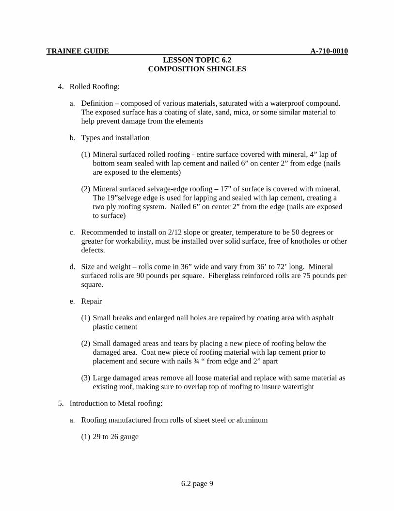
TRAINEE GUIDE A-710-0010 LESSON TOPIC 6.2
COMPOSITION SHINGLES
6.2 page 9
4. Rolled Roofing:
a. Definition – composed of various materials, saturated with a waterproof compound. The exposed surface has a coating of slate, sand, mica, or some similar material to help prevent damage from the elements
b. Types and installation
(1) Mineral surfaced rolled roofing - entire surface covered with mineral, 4” lap of bottom seam sealed with lap cement and nailed 6” on center 2” from edge (nails are exposed to the elements)
(2) Mineral surfaced selvage-edge roofing – 17” of surface is covered with mineral. The 19”selvege edge is used for lapping and sealed with lap cement, creating a two ply roofing system. Nailed 6” on center 2” from the edge (nails are exposed to surface)
c. Recommended to install on 2/12 slope or greater, temperature to be 50 degrees or greater for workability, must be installed over solid surface, free of knotholes or other defects.
d. Size and weight – rolls come in 36” wide and vary from 36’ to 72’ long. Mineral surfaced rolls are 90 pounds per square. Fiberglass reinforced rolls are 75 pounds per square.
e. Repair
(1) Small breaks and enlarged nail holes are repaired by coating area with asphalt plastic cement
(2) Small damaged areas and tears by placing a new piece of roofing below the damaged area. Coat new piece of roofing material with lap cement prior to placement and secure with nails ¾ “ from edge and 2” apart
(3) Large damaged areas remove all loose material and replace with same material as existing roof, making sure to overlap top of roofing to insure watertight
5. Introduction to Metal roofing:
a. Roofing manufactured from rolls of sheet steel or aluminum
(1) 29 to 26 gauge
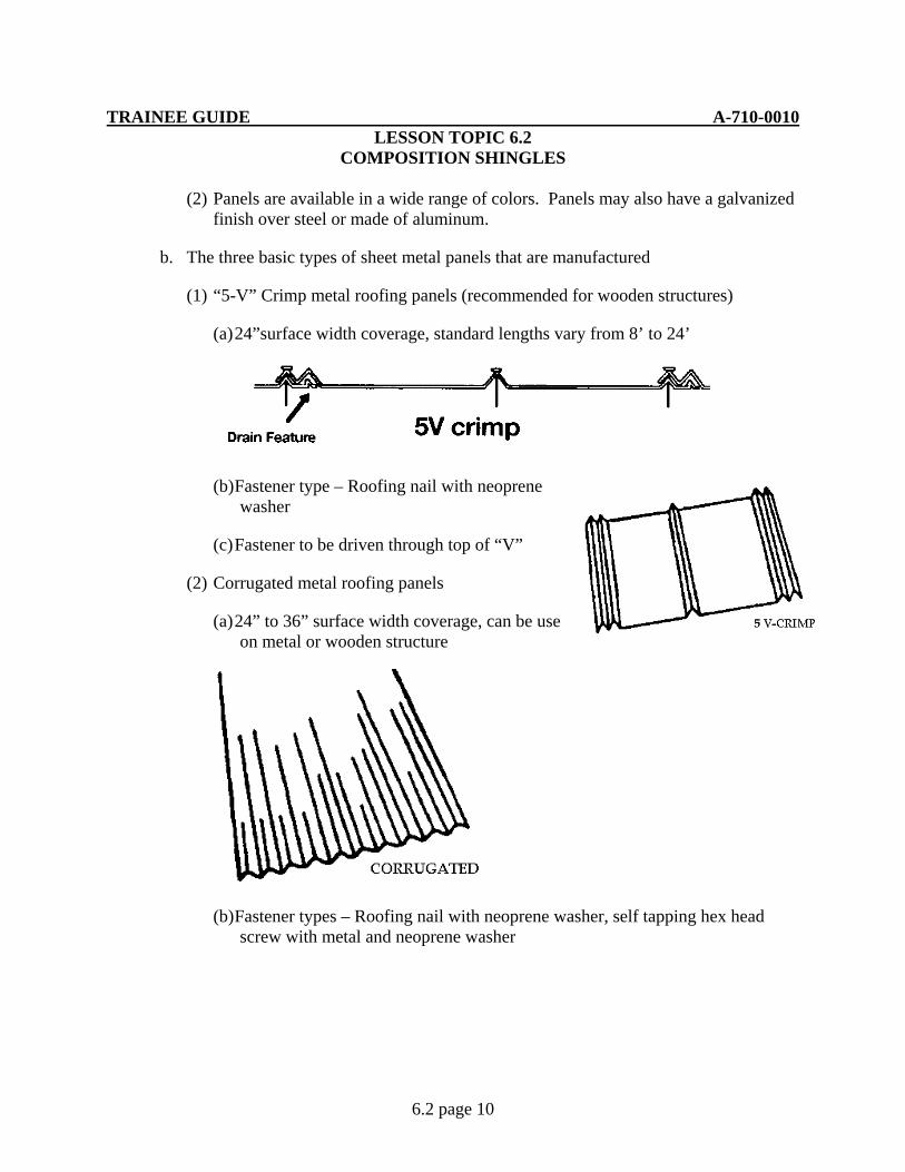
TRAINEE GUIDE A-710-0010 LESSON TOPIC 6.2
COMPOSITION SHINGLES
6.2 page 10
(2) Panels are available in a wide range of colors. Panels may also have a galvanized finish over steel or made of aluminum.
b. The three basic types of sheet metal panels that are manufactured
(1) “5-V” Crimp metal roofing panels (recommended for wooden structures)
(a) 24”surface width coverage, standard lengths vary from 8’ to 24’
(b) Fastener type – Roofing nail with neoprene washer
(c) Fastener to be driven through top of “V”
(2) Corrugated metal roofing panels
(a) 24” to 36” surface width coverage, can be use on metal or wooden structure
(b) Fastener types – Roofing nail with neoprene washer, self tapping hex head screw with metal and neoprene washer

TRAINEE GUIDE A-710-0010 LESSON TOPIC 6.2
COMPOSITION SHINGLES
6.2 page 11
(c) Fasteners to be driven or screwed thought the top of the curve in the corrugation (never in the valley)
(3) Double rib metal roofing panels
(a) 36” surface width coverage, can be used on wooden or metal structures
(b) Fasteners – self tapping hex head screw with metal and neoprene washer, huck rivets
(c) Fasteners to be screwed or riveted in flat area between ribs.

TRAINEE GUIDE A-710-0010 LESSON TOPIC 6.2
COMPOSITION SHINGLES
6.2 page 12
c. Repair
(1) Small holes require a patch of similar material, overlaying existing panel, attached by screws or rivets
(2) Large damaged areas may require part or full panel replacement. Remove fasteners and replace damaged panel making sure to place top of panel under existing panel and overlap bottom of panel

TRAINEE GUIDE A-710-0010 LESSON TOPIC 6.2
COMPOSITION SHINGLES
6.2 page 13
JOB SHEET 6.2-1
A. This job sheet will provide the information needed for you to apply composition shingles
B. Equipment required
a. 16’ tape measure
b. Chalk line
c. 22 oz. Framing hammer
d. Utility knife
e. Hook blades
f. Staple gun/swing hammer stapler
g. Roofing nails 1”
h. Shingles, 3 tab composition
i. Drip edge
j. Square nosed shovel
C. Reference:
1. Builder 3&2 Vol.2 NAVEDTRA 12521
2. Carpentry 3rd Edition, Delmar
D. Job steps:
Note: Refer to diagram sheet as necessary when performing the following tasks
1. Strip existing roof covering (if required)
a. Following applicable safety precautions, remove existing shingles, underlayment and drip edge from roof mock up. All removed materials will be cleaned up from job site prior to starting installation of shingles
b. Starting at the eave, use a square nosed shovel to lift existing shingles. Continue this process until all shingles are removed

TRAINEE GUIDE A-710-0010 LESSON TOPIC 6.2
COMPOSITION SHINGLES
6.2 page 14
c. Remove drip edge with a hammer and pry bar
2. Install drip edge along eaves. Secure the drip edge every 10” to 12” using roofing nails
3. Install underlayment
a. Starting at the eave, staple felt paper securely to roof sheathing. Install paper flush with the drip edge and rake. All valleys will be lapped a minimum of 12”
b. Install remaining courses lapping the top of the paper 2” and end lap of 4”
c. Upon completion of covering the entire roof with felt paper, place a 36” strip of felt paper down the center of each valley
d. After covering roof with felt paper, install drip edge along the rake
4. Layout roof for installation of shingles
a. Snap line 11 ½” from edge of drip edge
b. Find center of area to be covered. From this point snap a line extending from the eave to the ridge. Measure over 6” on ether side of the centerline and snap a chalk line from the eave to the ridge. Starting from the 11 ½” line snap a line every 10” to the ridge. This process will ensure proper alignment of every other course
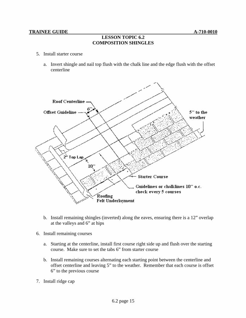
TRAINEE GUIDE A-710-0010 LESSON TOPIC 6.2
COMPOSITION SHINGLES
6.2 page 15
5. Install starter course
a. Invert shingle and nail top flush with the chalk line and the edge flush with the offset centerline
b. Install remaining shingles (inverted) along the eaves, ensuring there is a 12” overlap at the valleys and 6” at hips
6. Install remaining courses
a. Starting at the centerline, install first course right side up and flush over the starting course. Make sure to set the tabs 6” from starter course
b. Install remaining courses alternating each starting point between the centerline and offset centerline and leaving 5” to the weather. Remember that each course is offset 6” to the previous course
7. Install ridge cap

TRAINEE GUIDE A-710-0010 LESSON TOPIC 6.2
COMPOSITION SHINGLES
6.2 page 16
a. Cut shingles at tab creating 3 ridge caps
b. Center shingle tab on the ridge at the rake, flush with the drip edge
c. Install remaining ridge caps aligned with the first, maintaining the 5” to the weather