Embed Size (px)
Citation preview

INTERNATIONAL ASSOCIATION OF CLASSIFICATION SOCIETIES
Interpretationsof the International Conventionon Load Lines, 1966
IACS Int. 2007
Co
ntents, Pag
e 1
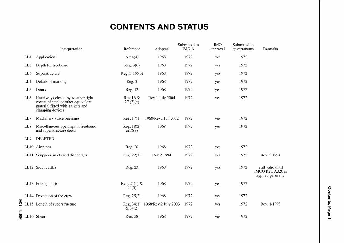
CONTENTS AND STATUS
Submitted to IMO Submitted toInterpretation Reference Adopted IMO A approval governments Remarks
LL1 Application Art.4(4) 1968 1972 yes 1972
LL2 Depth for freeboard Reg. 3(6) 1968 1972 yes 1972
LL3 Superstructure Reg. 3(10)(b) 1968 1972 yes 1972
LL4 Details of marking Reg. 8 1968 1972 yes 1972
LL5 Doors Reg. 12 1968 1972 yes 1972
LL6 Hatchways closed by weather tight Reg.16 & Rev.1 July 2004 1972 yes 1972covers of steel or other equivalent 27 (7)(c)material fitted with gaskets andclamping devices
LL7 Machinery space openings Reg. 17(1) 1968/Rev.1Jun 2002 1972 yes 1972
LL8 Miscellaneous openings in freeboard Reg. 18(2) 1968 1972 yes 1972and superstructure decks &18(3)
LL9 DELETED
LL10 Air pipes Reg. 20 1968 1972 yes 1972
LL11 Scuppers, inlets and discharges Reg. 22(1) Rev.2 1994 1972 yes 1972 Rev. 2 1994
LL12 Side scuttles Reg. 23 1968 1972 yes 1972 Still valid untilIMCO Res. A320 is
applied generally
LL13 Freeing ports Reg. 24(1) & 1968 1972 yes 197224(5)
LL14 Protection of the crew Reg. 25(2) 1968 1972 yes 1972
LL15 Length of superstructure Reg. 34(1) 1968/Rev.2 July 2003 1972 yes 1972 Rev. 1/1993& 34(2)
LL16 Sheer Reg. 38 1968 1972 yes 1972
IAC
S Int. 2004
Co
ntents, Pag
e 2
IAC
S Int. 2006
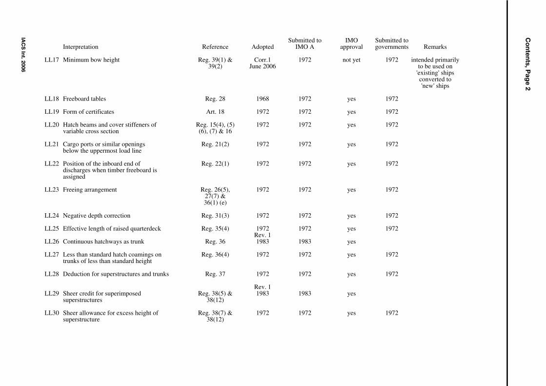
Submitted to IMO Submitted toInterpretation Reference Adopted IMO A approval governments Remarks
LL17 Minimum bow height Reg. 39(1) & Corr.1 1972 not yet 1972 intended primarily39(2) June 2006 to be used on
'existing' shipsconverted to'new' ships
LL18 Freeboard tables Reg. 28 1968 1972 yes 1972
LL19 Form of certificates Art. 18 1972 1972 yes 1972
LL20 Hatch beams and cover stiffeners of Reg. 15(4), (5) 1972 1972 yes 1972variable cross section (6), (7) & 16
LL21 Cargo ports or similar openings Reg. 21(2) 1972 1972 yes 1972below the uppermost load line
LL22 Position of the inboard end of Reg. 22(1) 1972 1972 yes 1972discharges when timber freeboard isassigned
LL23 Freeing arrangement Reg. 26(5), 1972 1972 yes 197227(7) & 36(1) (e)
LL24 Negative depth correction Reg. 31(3) 1972 1972 yes 1972
LL25 Effective length of raised quarterdeck Reg. 35(4) 1972 1972 yes 1972Rev. 1
LL26 Continuous hatchways as trunk Reg. 36 1983 1983 yes
LL27 Less than standard hatch coamings on Reg. 36(4) 1972 1972 yes 1972trunks of less than standard height
LL28 Deduction for superstructures and trunks Reg. 37 1972 1972 yes 1972
Rev. 1LL29 Sheer credit for superimposed Reg. 38(5) & 1983 1983 yes
superstructures 38(12)
LL30 Sheer allowance for excess height of Reg. 38(7) & 1972 1972 yes 1972superstructure 38(12)
Co
ntents, Pag
e 3
IAC
S Int. 2006
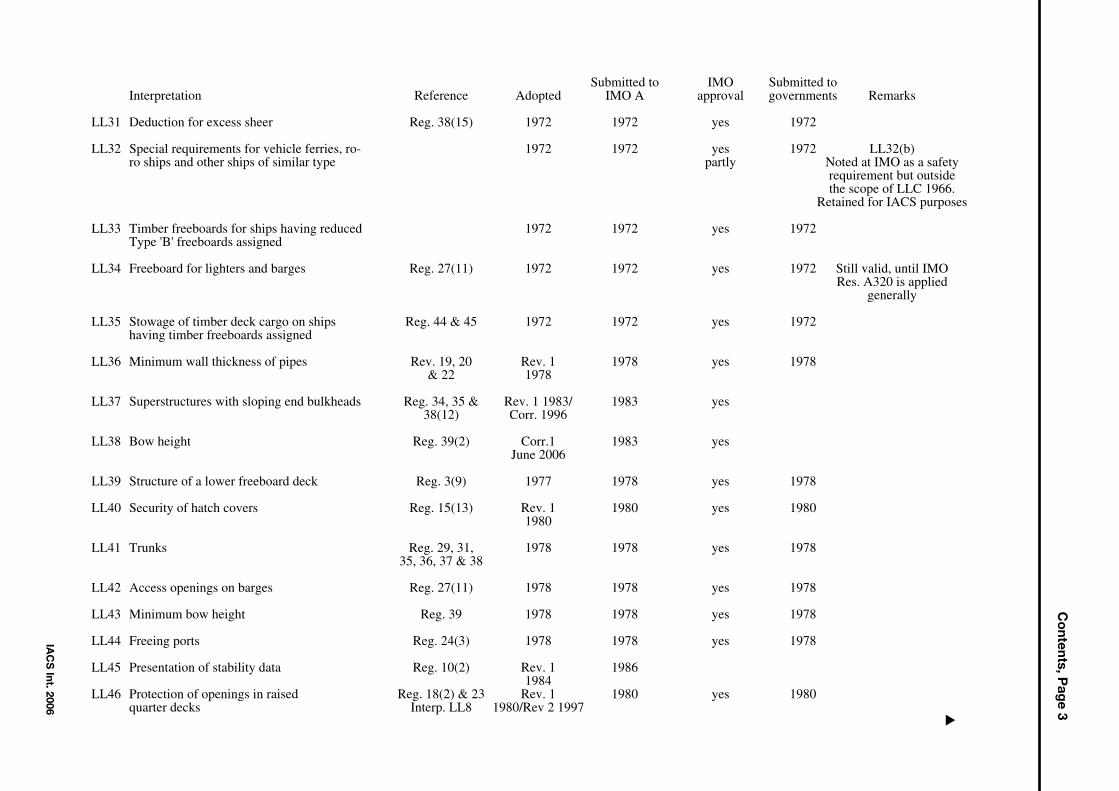
Submitted to IMO Submitted toInterpretation Reference Adopted IMO A approval governments Remarks
LL31 Deduction for excess sheer Reg. 38(15) 1972 1972 yes 1972
LL32 Special requirements for vehicle ferries, ro- 1972 1972 yes 1972 LL32(b)ro ships and other ships of similar type partly Noted at IMO as a safety
requirement but outsidethe scope of LLC 1966.
Retained for IACS purposes
LL33 Timber freeboards for ships having reduced 1972 1972 yes 1972Type 'B' freeboards assigned
LL34 Freeboard for lighters and barges Reg. 27(11) 1972 1972 yes 1972 Still valid, until IMORes. A320 is applied
generally
LL35 Stowage of timber deck cargo on ships Reg. 44 & 45 1972 1972 yes 1972having timber freeboards assigned
LL36 Minimum wall thickness of pipes Rev. 19, 20 Rev. 1 1978 yes 1978& 22 1978
LL37 Superstructures with sloping end bulkheads Reg. 34, 35 & Rev. 1 1983/ 1983 yes38(12) Corr. 1996
LL38 Bow height Reg. 39(2) Corr.1 1983 yesJune 2006
LL39 Structure of a lower freeboard deck Reg. 3(9) 1977 1978 yes 1978
LL40 Security of hatch covers Reg. 15(13) Rev. 1 1980 yes 19801980
LL41 Trunks Reg. 29, 31, 1978 1978 yes 197835, 36, 37 & 38
LL42 Access openings on barges Reg. 27(11) 1978 1978 yes 1978
LL43 Minimum bow height Reg. 39 1978 1978 yes 1978
LL44 Freeing ports Reg. 24(3) 1978 1978 yes 1978
LL45 Presentation of stability data Reg. 10(2) Rev. 1 19861984
LL46 Protection of openings in raised Reg. 18(2) & 23 Rev. 1 1980 yes 1980quarter decks Interp. LL8 1980/Rev 2 1997
▼

Co
ntents, Pag
e 4
IAC
S Int. 1996/2006
Submitted to IMO Submitted toInterpretation Reference Adopted IMO A approval governments Remarks
LL47 Guard rails Rev. 2.1 1980 yes 1980Oct 2006
LL48 Moulded depth and freeboard Reg. 3(5) (c), Rev.1 1983 Rev. 1 yescalculation 3(9) & 40(1) 1983
LL49 Air pipe closing devices Reg. 20 1980 1980 yes 1980
LL50 Protection of crew Reg. 25(4), 26(2) Rev.4.1 Oct 98 Rev. 4 yes& 27(7) 1998
LL51 Freeboards greater than minimum Reg. 2(5) Rev.1 1986 Rev.2 yes1997
LL52 Weathertight closing appliances Reg. 19(4) 1983 1983 yesfor ventilators
LL53 Treatment of moonpools 1987 1987 Parts of paragraphs 3.7.2.3 and 3.7.3.4 of
MODU Code have beenextended to other ships
LL54 Effective length of superstructures Reg. 35(3) 1989
LL55 Least Moulded Depth for a shipwith a Rake of Keel Reg. 3 (1) 1993
LL56 Block Coefficient of a Pontoon Reg. 3 (7) 1993
LL57 Block Coefficient of a Multi-hull Craft 1996
LL58 Machinery space and emergency generator room ventilator coaming heights 1997
LL59 Cargo manifold gutter bars - freeing arrangementsand intact stability 1997
LL60 Freeing ports in way of wells in combination withopen superstructures 1997, Corr. 1 April 1998
LL61 Method of correction for the effect of free surface of liquids in tanks (Regulation 10(2), UR L3 andUI LL45 1997
LL62 Side Scuttles, Windows and Skylights Reg. (3) 1997

IAC
S Int. 2007
Contents, P
age 5Submitted to IMO Submitted to
Interpretation Reference Adopted IMO A approval governments Remarks
LL63 Treatment of steps and recesses in transverse subdivisionbulkheads : IMO Res. A.320 Rev.1 July 2004
LL64 Non-Weathertight Hatchcovers above Superstructure Deck Rev.4 July 2005
LL65 Ships with assigned or reassigned reduced freeboards andintended to carry deck cargo Rev.1 June 2007
LL66 Hatch Cover Stress/Deflection Calculation(Res. MSC.143(77), 2005 LL Protocol Regulation 16(5) (a) & (b)) Oct 2003
LL67 Endorsement of Certificates with the Date of Completion of the Rev.1 Nov 2005Survey on which they are Based
LL68 Position of Freeboard Deck on Float On/Float Off Barge Carriers May 2004(Regulation 3((9))
LL69 Interpretation to 1966 ICLL Reg. 27 May 2004
LL70 Corrosion Margin for Hatch Cover Design Jan 2005
LL71 Similar Stage of Construction April 2005
LL72 Interpretation to ICLL Regulation 27 Sept 2005
Application (Article (4))
Even where the increase in draught is only of the order of 1 in or 2 in there should be no relaxation fromthe condition that existing ships comply with all the requirements.
Depth for freeboard (Regulation 3(6))
The correction for thickness of sheathing on the exposed freeboard deck T(L-S)/L is applicable only whendeck is completely sheathed between superstructures. In other cases the correction should be Tl/L, where l =length of sheathed area which extends from side to side. Only wood sheathing should be considered.
Superstructure (Regulation 3 (10)(b))
A bridge or poop shall not be regarded as enclosed unless access is provided for the crew starting fromany point on the uppermost complete exposed deck or higher to reach machinery and other workingspaces inside these superstructures by alternative means which are available at all times when bulkheadopenings are closed.
Details of marking (Regulation 8)
'Permanently marked' is considered to include welding of the marks on the sides of the ship provided theusual precautions as to material, electrodes, etc. are observed.
LL1(1968)
IACS Int. 1980
LL1–LL4
LL4(1968)
▼▼▼▼
▼▼▼▼
LL2(1968)
LL3(1968)
Doors (Regulation 12)
(a) Doors should generally open outwards to provide additional security against the impact of the sea.Doors which open inwards are to be especially approved.
(b) Portable sills should be avoided. However, in order to facilitate the loading/unloading of heavyspare parts or similar, portable sills may be fitted on the following conditions:
(i) They must be installed before the ship leaves port.(ii) Sills are to be gasketed and fastened by closely spaced through bolts.(iii) Whenever the sills are replaced after removal, the weathertightness of the sills and the
related doors must be verified by hose testing. The dates of removal, replacing and hose testing shall be recorded in the ship's log book.
Hatchways closed by weather tight coversof steel or other equivalent material fittedwith gaskets and clamping devices(Regulations 16 and 27(7)(c))
Regulation 16:
Where hatchways are fitted with coamings of standard height, no extra strengthening (beyond what isrequired in the Load Line Convention) shall be required for covers loaded with cargo, even if densecargo, provided the load does not exceed 1,75 ton/m2 (in position 1)*.
Regulation 27(7)(c):
No extra strengthening is recommended for hatchway covers on vessels* which are assigned freeboardsless than those based on Table B, except for flush hatchway covers which are fitted on the freeboard deckforward of the quarter length, in which case the section modulus and the moment of interia shall beincreased 15% over that required by Regulation 16.
*Bulk Carriers:
For the hatch covers on Bulk Carriers, as defined in UR Z11.2.2, contracted for construction on or after 1July 1998, the hatch cover load and strength requirements are to be in accordance with IACS UnifiedRequirement S21, “Evaluation of Scantlings of Hatch Covers of Bulk Carrier Cargo Holds”.
Note:1. The “contracted for construction” date means the date on which the contract to build the
vessel is signed between the prospective owner and the shipbuilder. For further details regarding the date of “contract for construction”, refer to IACS Procedural Requirement (PR) No. 29.
Machinery space openings (Regulations 17(1), 26(1), 27(9) and 27(10)
Where casings are not protected by other structures, double doors should be required for type A or type Bships assigned freeboards less than those based on Table B1. An inner sill of 230 mm in conjunctionwith the outer sill of 600 mm is recommended.
LL5–LL7
LL5(1968)
LL6(1968)(Rev. 1May 1999)(Rev.2July 2004)
LL7(1968)(Rev.1June2002)
IACS Int. 1980/Rev.1 2002
Footnote: 1 “Based on Table B” means without any reduction in accordance with Regulation 27(9) or (10).
Note: Changes introduced in Rev.1 are to be uniformly implemented by IACS Members and Associatesfrom 1 January 2003.
END
END
END

LL8–LL10
Miscellaneous openings in freeboard andsuperstructure decks(Regulation 18 (2) & 18 (3))
Regulation 18 (2):
Only those doorways in deckhouses leading to or giving access to companionways leading below, needto be fitted with doors in accordance with Regulation 12.
Alternatively, if stairways within a deckhouse are enclosed within properly constructed companionwaysfitted with doors complying with Regulation 12, the external door need not be watertight.
Where an opening in a superstructure deck or in the top of a deckhouse on the freeboard deck whichgives access to a space below the freeboard deck or to a space within an enclosed superstructure isprotected by a deckhouse, then it is considered that only those side scuttles fitted in spaces which givedirect access to an open stairway need be fitted with deadlights in accordance with Regulation 23. Acabin is considered to provide adequate protection against the minimal account of water which will enterthrough a broken side scuttle glass fitted on the second tier.
Regulation 18 (3):
In the application of Regulation 18 it is understood that:
(i) where access is provided from the deck as an alternative to access from the freeboard deck in accordance with Regulation 3 (10) (b) then the height of sills into a bridge or poop should be 380 mm. The same consideration should apply to deckhouses on the freeboard deck.
(ii) where access is not provided from above, the height of the sills to doorways in a poop bridge or deckhouse on the freeboard deck should be 600 mm.
(iii) where the closing appliances of access openings in superstructures and deckhouses are not in accordance with Regulation 12, interior deck openings are to be considered exposed, i.e. situated in the open deck.
Deleted
Air pipes (Regulation 20)
For ships assigned timber freeboards the air pipes should be provided with automatic closing appliances.
LL8(1968)
LL10(1968)
LL9
IACS Req. 1990
▼▼▼▼
▼▼
LL11
Scuppers, inlets and discharges(Regulation 22 (1))
It is considered that an acceptable equivalent to one automatic non-return valve with a positive means ofclosing from a position above the freeboard deck would be one automatic non-return valve and one sluicevalve controlled from above the freeboard deck.
Where two automatic non-return valves are required, the inboard valve must always be accessible underservice condition, i.e., the inboard valve should be above the level of the tropical load water line. If this isnot practicable, then, provided a locally controlled sluice valve is interposed between the two automaticnon-return valves, the inboard valve need not to be fitted above the LWL.
Where sanitary discharges and scuppers lead overboard through the shell in way of machinery spaces, thefitting to shell of a locally operated positive closing valve, together with non-return valve inboard, isconsidered to provide protection equivalent to the requirements of Regulation 22 (1).
It is considered that the requirements of Regulation 22 (1) for non-return valves are applicable only tothose discharges which remain open during the normal operation of a vessel. For discharges which mustnecessarily be closed at sea, such as gravity drains from topside ballast tanks, a single screw down valveoperated from the deck is considered to provide efficient protection.
The inboard end of a gravity discharge which leads overboard from an enclosed superstructure or spaceis to be located above the water line formed by a 5 degree heel, to port or starboard, at a draftcorresponding to the assign summer freeboard.
It is considered that the position of the inboard end of discharges should be related to the timber summerload waterline when timber freeboard is assigned.
Refer to the attached Table for the acceptable arrangements of scuppers, inlets, and discharges.
For garbage chutes it is considered that an acceptable equivalent to the non-return valve with a positivemeans of closing from a position above the freeboard deck would be two gate valves controlled from theworking deck of the chute. The lowest gate valve should, in addition, be controlled from a positionabove the freeboard deck. An interlock system between the two valves should be arranged.
It is recommended that the inboard end be located above the waterline formed by an 8.5 degree heel, toport or starboard, at a draft corresponding to the assigned summer freeboard, but not less than 1000mmabove the summer waterline.
Where the inboard end of the garbage chute exceeds 0.01L above the summer waterline, valve controlfrom the freeboard deck is not required, provided the inboard gate valve is always accessible underservice conditions.
The distance between the two gate valves should be adequate to allow the smooth operation of theinterlock system.
Alternatively, the upper gate valve may be replaced by a hinged weathertight cover at the inboard end ofthe chute together with a discharge flap which replaces the lower gate valve.
The cover and flap are to be arranged with an interlock so that the discharge flap cannot be operated untilthe hopper cover is closed.
The chute is to be constructed of material of substantial thickness up to, and including, the cover.
The gate valve(s) controls and/or hinged cover are to be clearly marked : “Keep closed when not in use”.
IACS Req. 1990/Rev. 2 1994
▼
LL11(1968)(Rev. 11990)(Rev. 21994)
LL11
Where the inboard end of a garbage chute is below the margin line in a passenger ship, or the critical(crucial) waterline of a cargo ship of more than 100 m in length then:
(i) the inboard end hinged cover/valve is to be watertight.(ii) the valve is to be a screw-down non-return valve fitted in an easily accessible position above the
deepest subdivision load line.
(iii) the screw-down non-return valve is to be controlled from a position above the bulkhead deck and provided with open/shut indicators. The valve control is to be clearly marked : “Keep closed when not in use”.
Where plastic pipes are used for sanity discharges and scuppers, they are also subject to the requirementsof the Table, and the valve at the shell is to be operated from outside the space in which the valve islocated.
Where such plastic pipes are located below the summer waterline (timber summer load waterline), thevalve is to be operated from a position above the freeboard deck.
The portion of discharge line from the shell to the first valve as well as shell fittings and valves shell beof steel, bronze or other approved ductile material.
The approval of plastic piping in any location will be subject to the consideration of strength and firehazards involved with special reference to penetrations through bulkheads, decks or other significantcompartment boundaries.
Attention must also be paid to valid fire technical regulations.
LL11(Cont’d)
IACS Req. 1990/Rev. 2 1994
▼

)
▼
▼
LL11
IACS Req. 1990
D
isch
arge
s co
min
g fr
om e
nclo
sed
spac
es b
elow
the
free
boar
d de
ck
or o
n th
e fr
eebo
ard
deck
D
isch
arge
s co
min
g fr
om o
ther
sp
aces
Gen
eral
req
uire
men
t R
eg. 2
2(1)
whe
re
inbo
ard
end
< 0
.01L
ab
ove
SWL
Dis
char
ges
thro
ugh
mac
hine
ry
spac
e
Alte
rnat
ives
(R
eg. 2
2(1)
) w
here
inbo
ard
end
> 0
.01L
abo
ve S
WL
>
0.0
2L a
bove
SW
L
outb
oard
end
> 4
50m
m
belo
w F
B d
eck
or
< 6
00m
m a
bove
SW
L
Reg
. 22(
3)
othe
rwis
e R
eg. 2
2(4)
Sym
bols
: inbo
ard
end
of p
ipes
outb
oard
end
of p
ipes
pipe
s te
rmin
atin
g on
the
open
dec
k
non
retu
rn v
alve
with
out p
ositi
ve
mea
ns o
f clo
sing
non
retu
rn v
alve
with
pos
itive
m
eans
of c
losi
ng c
ontr
olle
d lo
cally
valv
e co
ntro
lled
loca
lly
rem
ote
cont
rol
norm
al th
ickn
ess
subs
tant
ial t
hick
ness
FB
Dec
k FB
D
eck
FB
Dec
k FB
D
eck
FB
Dec
k FB
D
eck
SW
L S
WL
SW
L S
WL
SW
L S
WL
Sup
erst
ruct
ure
or D
ecks
hous
e D
eck
cont
rol o
f the
val
ves
are
to b
e in
an
appr
oved
pos
ition
*/
1 2
3 4
5 6
7 8
9 10
11
12
13
14
*/
TWL
LL11
– T
he T
able
▼

Side scutters (Regulation 23)
For those vessels where the freeboard is reducted on account of subdivision characteristics, side scuttlesfitted outside the space considered flooded and which are below the final waterline shall be of the non-opening type.
Freeing ports (Regulation 24 (1) and 24 (5))
Regulation 24 (1)
On a flush deck ship with a substantial deckhouse amidships it is considered that the deckhouse providessufficient break to form two wells and that each could be given the required freeing port area based uponthe length of the 'well'. It would not then be allowed to base the area upon 0,7L.
In defining a substantial deckhouse it is suggested that the breadth of the deckhouse should be at least80% of the beam of the vessel, and that the passageways along the side of the ship should not exceed 1,5 m (4.9 ft) in width.
Where a screen bulkhead is fitted completely across the vessel, at the forward end of a midshipdeckhouse, this would effectively divide the exposed deck into wells and no limitation on the breadth ofthe deckhouse is considered necessary in this case.
It is considered that wells on raised quarterdecks should be treated as previously, i.e. as being onfreeboard decks.
Regulation 24 (5):
With zero or little sheer on the exposed freeboard deck or an exposed superstructure deck it is consideredthat the feeling port area should be spread along the length of the well.
Protection of the crew (Regulation 25 (2))
A guard rail should also be required for first tier deckhoused and for superstructures' ends.
LL12–LL14
LL12(1968)
LL13(1968)
LL14(1968)
IACS Req. 1990
▼▼▼▼
▼▼

LL15
LL15(1968)(Rev. 11993)(Rev. 2July 2003)
IACS Int. 1993/Rev.2 2003
▼▼
Length of superstructure (Regulation 34(1)and 34(2) )Regulation 34(1):
Where a superstructure bulkhead is recessed, the effective length of thesuperstructure shall be reduced by an amount equivalent in area to the area of therecess related to the breadth of the ship at the mid-length of the recess.
Where the recess is unsymmetrical about the centre line, the largest portion of therecess shall be considered as applying to both sides of the ship.
It is considered that such a recess need not be decked over.
Where a cargo hatchway, complying with the requirements of regulation 16 andhaving a coaming height that extends above the level of the superstructure deck, isfitted in the recess and covering the whole area of the recess, the hatchway may betaken into account as forming a part of the superstructure, and the effective length ofthe superstructure need not be reduced by the amount equivalent in area to the areaof the recess.
The hatchway coaming height shall be in accordance with Regulation 16(1), measuredfrom the superstructure deck level.
Regulation 34(2):
Where there is an extension to a superstructure, which extension has a breadth oneach side of the centre line at least 30% of the breadth of the ship, the effective lengthof the superstructure may be increased by considering an equivalent superstructurebulkhead in the form of a parabola. This parabola should extend from the extension atthe centre line and pass through the junction of the actual superstructure bulkheadwith the sides of the extension and extend to the sides of the ship. This parabolashould be completely contained within the boundary of the superstructure and itsextensions.
If the superstructure is set-in from the side, up to the limit allowed under Regulation 3(10), the equivalent bulkhead should be calculated on the basis of the actual breadthof the superstructure (not the breadth of the ship).
Note:
1. Changes introduced in Rev.2 (July 2003) are to be uniformly implemented by IACS Members and Associates from 1 January 2004.

Sheer (Regulation 38)
Where the height of a superstructure is less than standard, paragraph 12 may be applied except that thesuperstructure deck shall not be less than the minimum height of the superstructure above the virtualshear curve at any point.
For this purpose y shall be taken as the difference between the actual and minimum height of thesuperstructure at the end of sheer.
▼
LL16(1968)
LL16
▼
LL17- LL17(a)
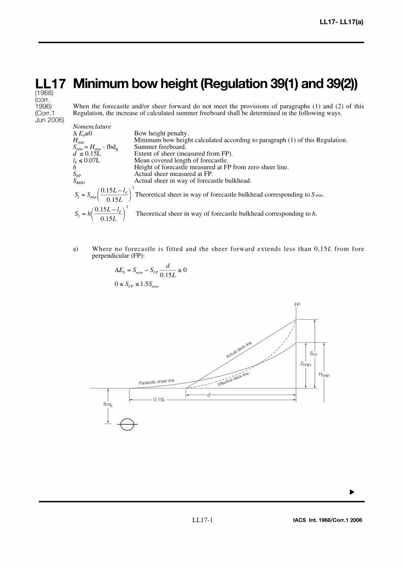
Minimum bow height (Regulation 39(1) and 39(2))
When the forecastle and/or sheer forward do not meet the provisions of paragraphs (1) and (2) of thisRegulation, the increase of calculated summer freeboard shall be determined in the following ways.
Nomenclature∆ E0≥0 Bow height penalty.Hmin Minimum bow height calculated according to paragraph (1) of this Regulation.Smin = Hmin - fbds Summer freeboard.d ≤ 0.15L Extent of sheer (measured from FP).lF ≤ 0.07L Mean covered length of forecastle.h Height of forecastle measured at FP from zero sheer line.SFP Actual sheer measured at FP.SBHD Actual sheer in way of forecastle bulkhead.
a) Where no forecastle is fitted and the sheer forward extends less than 0,15L from fore perpendicular (FP):
Hmin
Smin
SFP
0.15Ld
FP
Parabolic sheer line
Actual deck line
Effective deck line
fbds
∆E S Sd
LS S
mim FP
FP mim
0 0 150
0 1 5
= − ≥
≤ ≤.
.
S hL l
LhF
2
20 150 15
=−⎛
⎝⎞⎠
..
Theoretical sheer in way of forecastle bulkhead corresponding to .
S SL l
LSF
1
20 150 15
=−⎛
⎝⎞⎠min
..
minTheoretical sheer in way of forecastle bulkhead corresponding to .
IACS Int. 1968/Corr.1 2006
▼
LL17(1968)(corr.1996)(Corr.1Jun 2006)
LL17-1
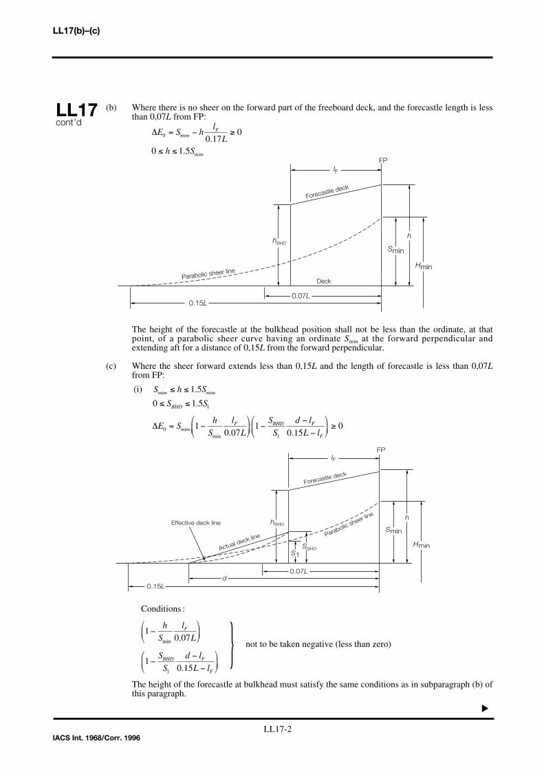
(b) Where there is no sheer on the forward part of the freeboard deck, and the forecastle length is less than 0,07L from FP:
The height of the forecastle at the bulkhead position shall not be less than the ordinate, at thatpoint, of a parabolic sheer curve having an ordinate Smin at the forward perpendicular andextending aft for a distance of 0,15L from the forward perpendicular.
(c) Where the sheer forward extends less than 0,15L and the length of forecastle is less than 0,07Lfrom FP:
The height of the forecastle at bulkhead must satisfy the same conditions as in subparagraph (b) ofthis paragraph.
not to be taken negative (less than zero)}Conditions :
10 07
10 151
−⎛
⎝⎜
⎞
⎠⎟
−−
−
⎛
⎝⎜
⎞
⎠⎟
h
S
l
L
S
S
d l
L l
F
BHD F
F
min .
.
Hmin
Smin
lF
0.15L
FP
Parabolic sheer line
Forecastle deck
h
0.07L
hBHD
d
S1SBHD
Effective deck line
Actual deck line
(i)
S h S
S S
E Sh
S
l
L
S
S
d l
L l
mim mim
BHD
mimF BHD F
F
≤ ≤
≤ ≤
= −⎛
⎝⎜
⎞
⎠⎟ −
−−
⎛
⎝⎜
⎞
⎠⎟ ≥
1 5
0 1 5
10 07
10 15
0
1
01
.
.
. .min
∆
Hmin
Smin
lF
0.15L
FP
Parabolic sheer line
Forecastle deck
h
0.07L
Deck
hBHD
∆E S hl
Lh S
mimF
mim
0 0 170
0 1 5
= − ≥
≤ ≤.
.
▼
LL17(b)–(c)
IACS Int. 1968/Corr. 1996
LL17cont’d
LL17-2

The height of the forecastle at the bulkhead position shall not be less than the ordinate, at that point, or a parabolic sheer curve having an ordinate h at the forward perpendicular and extending aft for a distance of 0,15L from the forward perpendicular.
In general, this interpretation should be applied to existing ships only, However, to suit exceptionaloperational requirements, and upon the special consideration by the Administration, the provision of thisinterpretation may also be applied to new ships.
not to be taken negative (less than zero)}Conditions :
10 07
10 151
−⎛⎝
⎞⎠
−−
−
⎛
⎝⎜
⎞
⎠⎟
l
L
S
S
d l
L l
F
BHD F
F
.
.
(ii)
h S
S S
E S h hl
L
S
S
d l
L l
mim
BHD
F BHD F
F
≤
≤ ≤
= −( ) + −⎛⎝
⎞⎠
−−
−
⎛
⎝⎜
⎞
⎠⎟
0 1 5
10 07
10 15
2
02
.
. .min∆
LL17(c)
LL17cont'd
IACS Int. 1968/Corr. 1996
▼▼
Hmin
Smin
lF
0.15L
FP
Parabolic sheer line
Forecastle deck
h
0.07L
hBHD
d
S2SBHD
Effective deck line
Actual deck line
Freeboard tables (Regulation 28)
(a) Type A ships
(i) Freeboards for Type A ships with lengths between 365 m and 400 m shall be determined by the following formula:
f = 221 + 16,10L - 0,02L2
where f is the freeboard in mmL is the length as defined in Regulation 3(1).
(ii) Freeboards for Type A ships with lengths of 400 m and above shall be the constant value, 3460 mm.
(b) Type B ships
(i) Freeboards for Type B ships with lengths between 365 m and 400 m shall be determined by the following formula:
f = - 587 + 23L - 0,0188L2
where f is the freeboard in mmL is the length as defined in Regulation 3(1).
(ii) Freeboards for Type B ships with lengths of 400 m and above shall be the constant value, 5605 mm.
Form of certificates (Article 18)
It is recommended that the model form of certificates given in Annex III of the Load Line Conventionshould be strictly adhered to and any deviations from this pattern should be avoided.
LL18–LL19
LL18(1968)
LL19(1972)
IACS Int. 1987
▼▼▼▼
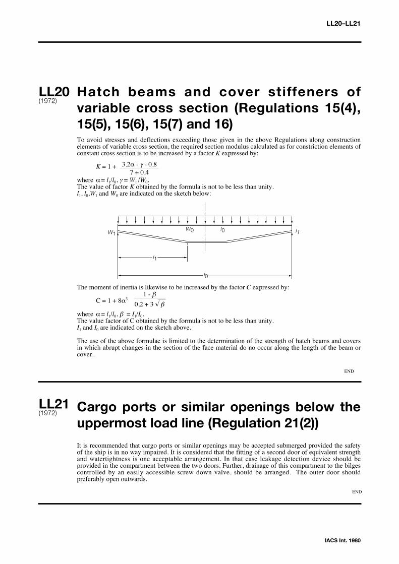
Hatch beams and cover stiffeners ofvariable cross section (Regulations 15(4),15(5), 15(6), 15(7) and 16)To avoid stresses and deflections exceeding those given in the above Regulations along constructionelements of variable cross section, the required section modulus calculated as for constriction elements ofconstant cross section is to be increased by a factor K expressed by:
K = 1 +
where α= l1/l0, γ = W1 /W0. The value of factor K obtained by the formula is not to be less than unity.l1, l0,W1 and W0 are indicated on the sketch below:
The moment of inertia is likewise to be increased by the factor C expressed by:
C = 1 + 8α3
where α= l1/l0, β = I1/I0. The value factor of C obtained by the formula is not to be less than unity.I1 and I0 are indicated on the sketch above.
The use of the above formulae is limited to the determination of the strength of hatch beams and coversin which abrupt changes in the section of the face material do no occur along the length of the beam orcover.
Cargo ports or similar openings below theuppermost load line (Regulation 21(2))
It is recommended that cargo ports or similar openings may be accepted submerged provided the safetyof the ship is in no way impaired. It is considered that the fitting of a second door of equivalent strengthand watertightness is one acceptable arrangement. In that case leakage detection device should beprovided in the compartment between the two doors. Further, drainage of this compartment to the bilgescontrolled by an easily accessible screw down valve, should be arranged. The outer door shouldpreferably open outwards.
LL20–LL21
LL20(1972)
LL21(1972)
IACS Int. 1980
END
END
3,2α - γ - 0,8 7 + 0,4
l1
l0 W0 W1
l0
l1
1 - β
0,2 + 3 √ β

Position of the inboard end of dischargeswhen timber freeboard is assigned(Regulation 22(1))
It is considered that the position of the inboard end of discharges should be related to the timber summerload waterline when timber freeboard is assigned.
Freeing arrangement (Regulations 26(5),27(7) and 36(1)(e))
Regulation 27(7): Freeing arrangements on ships having reduced B freeboard assigned and fittedwith bulwarks on the freeboard deck
For Type B ships with freeboards reduced by not more than 60% of the difference between B and Atables there shall be freeing port area in the lower part of the bulwarks equal to at least 25% of the totalarea of the bulkwarks.The upper edge of the sheer strake shall be kept as low as possible.
Regulations 26(5) and 36(1)(e): Freeing arrangements for Type A ships and Type B ships with trunks
It is considered that a freeing port area, in the lower part of the bulwarks, of 33% of the total area of thebulwarks provides the 'other effective freeing arrangements' mentioned in Regulation 26(5), and may beconsidered equivalent to the 50% open rails in way of trunks required by Regulation 36(1)(e).
Negative depth correction (Regulation 31(3))
When the height of a superstructure, raised quarterdeck or trunk is less than the corresponding standardheight, it is recommended that the calculated reduction be corrected in the ratio of the height of the actualsuperstructure, raised quarterdeck or trunk to the applicable standard height as defined in Regulation 33.
Effective length of raised quarterdeck(Regulation 35(4))It is recommended that the maximum effective length of 0,6L of a raised quarterdeck which is stipulatedby Regulation 35(4), is to be measured from the after perpendicular even where a poop is fitted inconjunction with the raised quarterdeck.
LL22(1972)
LL22 - LL25
LL23(1972)
LL24(1972)
LL25(1972)
IACS Int. 1980
▼▼▼▼
▼▼▼▼

Continuous hatchways as trunk (Regulation 36)
It is recommended that continuous hatchways may be treated as a trunk in the freeboard computationprovided Regulation 36 is complied with in all respects.
The trunk deck stringer referred to in Regulation 36(1)(b) may be fitted outboard of the trunk sidebulkhead in association with the following:
(i) The stringer so formed is to provide a clear walkway of at least 450 mm in width on each side of the ship.
(ii) The stringer is to be of solid plate efficiently supported and stiffened.(iii) The stringer is to be as high above the freeboard deck as practicable. In the freeboard calculation,
the trunk height is to be reduced by at least 600 mm or by the actual difference between the top of the trunk and the stringer, whichever is greater.
(iv) Hatch cover securing appliances are to be accessible from the stringer or walkway.(v) The breadth of the trunk is to be measured between the trunk side bulkheads.(vi) Regulation 36 is to be complied with in all other respects.
Less than standard hatch coamings ontrunks of less than standard height(Regulation 36(4))
In the case where trunk height is less than standard and the trunk hatch coamings are also of less thanstandard height, or omitted entirely, doubt may arise whether the trunk hatchways are located in position1 or position 2 and, consequently, about the reduction to be made in the actual trunk height. It isconsidered that in these cases the reduction from the actual height of trunk on account of insufficienthatch coaming height shall be taken as the difference between 600 mm and the actual height of coaming,or 600 mm if no hatch coamings are fitted. Reduction in the actual height of trunk shall not be requiredin cases where only small hatches with less than standard height are fitted in the trunk deck for whichdispensation from the requirement of standard coaming height may be given.
Deduction for superstructures and trunks(Regulation 37)
For the purpose of applying the table 'Percentage of Deduction for Type B ships' in Regulation 37(2) it isconsidered that any detached superstructure abaft midship whose after bulkhead is located 0,05L or moreforward of the after perpendicular may be treated as a detached bridge.A superstructure whose after bulkhead is located within 0,05L from the after perpendicular shall notqualify as a detached bridge.Any excess in the height of such a superstructure, which does not extend to the after perpendicular,cannot be regarded as contributing to the sheer allowance contemplated in Regulation 38(12).
LL26 - LL28
LL26(1972)(Rev. 11983)
LL27(1972)
LL28(1972)
▼▼▼▼
▼▼

LL29
Sheer Credit for SuperimposedSuperstructures (Regulation 38(5), 38(7) and 38(12)(a) Regulation 38(5): Superstructures superimposed on a complete superstructure.
In applying Regulation 38(5) (sheer on a complete superstructure ship) where there is an enclosed poopor forecastle superimposed on a complete superstructure, sheer credit shall be allowed for such a poop orforecastle, according to the method of Regulation 38(12) as shown in Fig 1.
(b) Regulation 38(7): Superstructures superimposed on a forecastle or poop (ie a stepped forecastle orpoop).
In applying Regulation 38(7) and 38(12) where a poop or forecastle consists of two layers, the methodshown in Fig 2 shall be used:
In the above the following definitions apply:Z is as per Reg 38(5).Zv is the end ordinate of a virtual standard parabolic curve taken through the point "X". If Zv is greaterthan (Z+h), the end ordinate shall be (Z+h), in which case point "X" shall be disregarded and curve (2)not taken into account.When the length of the first tier superstructure is greater than 0.5L, the virtual standard parabolic curveshall commence at amidships as indicated in Fig 1.
LL29(1972)(Rev.11983)
IACS Int. 1984
▼▼
Fig. 1
F.T.
Zv = Z ( )
x Superstructure deck
Freeboard deck
Standard height
1
2
L 2
L 2
Zv Z
h
2
Fig. 2
F.T.
Zv = Z ( ) Freeboard deck
Standard height
1
2
1
2
1
Z
h
Zv
2
2
Sheer allowance for excess height ofsuperstructure (Regulation 38(7) and 38(12))
As Regulation 38(7) and (12) does not refer to a raised quarter deck it is recommended that credit underthis paragraph be given for this type of superstructure only when the height of the raised quarterdeck isgreater than the standard height of 'other superstructures' as defined in Regulation 33, and only for theamount by which the actual height of the raised quarterdeck exceeds that standard height.
Deduction for excess sheer (Regulation 38(15))
Since no stipulation is made as to the height of the superstructure referred to in Regulation 38(15), it isrecommended that the height of this superstructure shall be related to its standard height. When theheight of the superstructure or raised quarterdeck is less than standard, the reduction shall be in the ratioof the actual to the standard height thereof.
Special requirements for vehicle ferries, ro-ro ships and other ships of similar type
(a) Stern, bow and side doors of large dimensions, when manual devices would not be readily accessible, are to be normally secured by means of power systems. Alternative means of securing are also to be provided for emergency use in case of failure of the power systems.
(b) In vehicle ferries which also carry passengers, all access doors or hatchways to spaces below the vehicle deck, which may be used at sea, are to have sills or coamings not less than 380 mm in height above the vehicle deck, and are to be provided with doors or covers considered weather-tight in relation to their position.
The vehicle deck, referred to in the preceding paragraph is the deck above which the stern, bow or side doors are fitted, or the first deck above the load waterline.
LL30–LL32
LL30(1972)
LL31(1972)
LL32(1972)
IACS Int. 1984
▼▼▼▼
▼▼

Timber freeboards for ships having reducedType B freeboards assigned
It is understood that some Administrations accept that timber freeboards may be assigned to ships withreduced Type B freeboards, provided the timber freeboards are calculated on the basis of the ordinaryType B freeboard.
It is recommended that Regulation 45(2) and (3) is interpreted or, if necessary, amended such that theTimber Winter mark and/or the Timber Winter North Atlantic mark are placed at the same level as thereduced Type B Winter mark when the computed Timber Winter mark and/or the computed TimberWinter North Atlantic mark fall below the reduced Type B Winter mark.
Freeboard for lighters and barges(Regulation 27(11))In applying Regulation 27(11) to deck cargo barges it is recommended that only Type B freeboard can beassigned, even if the barges possess the same integrity of exposed decks and equivalent safety againstflooding as normal tank barges.
This view is taken as a result of the consideration that Type A freeboard can only be assigned to liquidcargo barges.
It is further concluded that deck cargo can only be carried on barges to which Type B freeboard isassigned.
Stowage of timber deck cargo on shipshaving timber freeboards assigned(Regulations 44 and 45)
It is recommended that for the purpose of applying Regulation 45 the timber deck cargo shall extend asfar outboard as possible due allowance being given for obstructions such as guard rail, stanchions,uprights, etc.
LL33–LL35
LL33(1972)
LL34(1972)
LL35(1972)
IACS Int. 1984
▼▼▼▼
▼▼

Minimum wall thickness of pipes(Regulations 19, 20 and 22)For pipes covered by the above Regulations the following minimum wall thicknesses are recommended:
(a) (i) For scupper and discharge pipes, where substantial thickness is not required:(ii) For venting pipes other than specified under (c):
external diameter of pipes equal to or less than 155 mm: thickness not less than 4,5 mmexternal diameter of pipes equal to or more than 230 mm: thickness not less than 6,0 mmintermediate sizes are to be determined by linear interpolation.
(b) For scupper and discharge pipes where substantial thickness is required:external diameter of pipes equal to or less than 80 mm: thickness not less than 7,0 mmexternal diameter of pipes 180 mm: thickness not less than 10,0 mmexternal diameter of pipes equal to or more than 220 mm: thickness not less than 12,5 mmintermediate sizes are to be determined by linear interpolation.
(c) For venting pipes in position 1 and 2 leading to spaces below the freeboard deck or to spaces within closed superstructures:
external diameter of pipes equal to or less than 80 mm: thickness not less than 6,0 mmexternal diameter of pipes equal to or more than 165 mm: thickness not less than 8,5 mmintermediate sizes are to be determined by linear interpolation.
LL36
LL36(1975)(Rev. 11978)
IACS Int. 1987
▼▼

Superstructures with sloping end bulkheads(Regulations 34, 35 and 38(12))
When taking account of superstructures which have sloping end bulkheads in the calculations offreeboards, such superstructures shall be dealt with in the following manner:
(a) Regulation 34
(i) When the height of superstructure, clear of slope, is equal to or smaller than the standard height, length S is to be obtained as shown in Fig 1.
(ii) When the height is greater than the standard, length S is to be obtained as shown in Fig 2.(iii) The foregoing will apply only when the slope, related to the base line, is 15° or greater. Where
the slope is less than 15°, the configuration will be treated as sheer.
(b) Regulation 35
When the height of the superstructure, clear of the slope, is less than the standard height, its effectivelength E shall be its length S as obtained from (a)(i), reduced in the ratio of the actual height to thestandard height.
h1a
1 2 S = 1 + 2/2
h = standard height
Fig. 2 Height of superstructure greater than the standard height
E = S
ha
1 2
S = 1+ 2/2
Fig. 1 Height of superstructure equal to or smaller than the standard height h
E =Sha/h
LL37
IACS Int. 1983/Corr. 1996
LL37(1975)(Rev. 11983)(Corr.1996)
▼
LL37-1
LL37
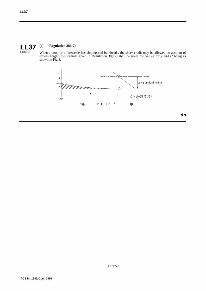
(c) Regulation 38(12)
When a poop or a forecastle has sloping end bulkheads, the sheer credit may be allowed on account ofexcess height, the formula given in Regulation 38(12) shall be used, the values for y and L' being asshown in Fig 3.
����L'
S = (y/3) (L'/L)
h = standard height
Fig. 3 Sheer credit s for excess height
h
y
AP
IACS Int 1983/Corr. 1996
LL37cont’d
▼▼
LL37-2

Bow Height (Regulation 39(2))
1 When calculating bow height, the sheer of the forecastle deck may be taken into account, even if the length of the forecastle is less than 0.15L, but greater than 0.07L, provided that the forecastle height is not less than one half of standard height of superstructure as defined in Regulation 33 between 0.07L and the forward terminal.
2 Where the forecastle height is less than one half of standard height of superstructure, as defined in Regulation 33, the credited bow height may be determined as follows(Figs 1 and 2 illustrate the intention of 2.1 and 2.2 respectively):
2.1 When the freeboard deck has sheer extending from abaft 0.15L, by a parabolic curve having its origin at 0.15L abaft the forward terminal at a height equal to the midship depth of the ship, extended through the point of intersection of forecastle bulkhead and deck, and up to apoint at the forward terminal not higher than the level of the forecastle deck. However, if the value of the height denoted ht on Fig 1 is smaller than the value of the height denoted hb, then ht, may be replaced in the available bow height.
2.2 When the freeboard deck has sheer extending for less than 0.15L or has no sheer, by a line from the forecastle deck at side at 0.07L extended parallel to the base line to the forward terminal.
hf = Half standard height of superstructure as defined in regulation 33.
Fig. 2
0.15L 0.07L
Cre
dite
d bo
whe
ight
F.T.
hf
hf
Fig. 1
0.15L
xb
hbht
zbzt
0.07L
Standard parabola
Cre
dite
d bo
whe
ight
F.T.
hfhf
LL38
IACS Int. 1983/Corr.1 2006
▼▼
LL38(1976)(Rev. 11983)(Corr.1Jun 2006)
h ZL
xZt b
bt=
⎛
⎝⎜
⎞
⎠⎟ −
0 152
.

Structure of a lower freeboard deck(Regulation 3(9))
When a lower deck is designated as the freeboard deck, it shall be continuous in fore and aft direction aswell as athwartship. Such freeboard deck as a minimum shall consist of suitably framed stringers at theship sides and transversely at each watertight bulkhead which extends to the upper deck, within cargospaces. The width of these stringers shall not be less than can be conveniently fitted having regard to thestructure and the operation of the ship. Any arrangement of stringers shall be such that structuralrequirement can also be met.
NOTE
Member Societies formulated this Interpretation in order to have a guide when judging whether astructure below the uppermost complete deck can be designated as freeboard deck in terms of Regulation3(9) for the application of tonnage regulation. This was done, although it is obvious that such a structurehas no significance with regard to the philosophy of the Load Line Convention.
Nevertheless it is felt that it would be preferable if tonnage and load line matters could be clearlyseparated by deleting from the Load Line Convention the reference to a lower deck being designated asthe freeboard deck.
Security of hatch covers (Regulation 15(13))
Acceptable equivalent means to steel bars shall consist of devices and materials which will providestrength equivalent to, and elasticity not greater than that of, steel.
Steel wire ropes cannot be regarded as satisfactory equivalent means.
Care is to be taken that tarpaulins are adequately protected from the possibility of damage arising fromthe use of securing devices which do not provide a flat bearing surface.
Trunks (Regulations 29, 31, 35, 36, 37 and 38))
(a) Where the length of a trunk, corrected for breadth and height as may be appropriate, can be included in the effective length used for calculating the correction for superstructures in accordance with Regulation 37, it shall not be taken into account for calculating the total length Sfor the purpose of sheer correction according to Regulation 38(13).
(b) The effective length of superstructures E which is used for calculating the freeboard correction according to Regulation 29 shall be determined excluding the length of trunks.
▼
LL39–LL41
LL39(1977)
LL40(1977)Rev. 11980)
LL41(1978)
IACS Int. 1984
▼▼▼▼

(c) The inclusion of a trunk in the calculation of freeboard need not prohibit the fitting of openings in the bulkheads of adjacent superstructures such as poops, bridges or forecastles provided there is no direct communication between the superstructure and the trunk.
(d) The sides of a trunk included in the calculation of freeboard shall be intact. Side scuttles of the non-opening type and bolted manhole covers may be allowed.
Access openings on barges (Regulation 27(11))
(a) Since Regulation 27(11) does not contain any indication as to what size the term 'small access openings' refers it is recommended that such openings should not be greater than 1,5 m2 where a freeboard reduction of 25% is granted.
(b) Access plates are considered as being equivalent to an intact deck for unmanned barges, thereby allowing for a 25% reduction in freeboard, provided they are secured by closely spaced bolts, their joining parts are properly gasketed and their arrangements, for all practical purposes, have equivalent structural integrity and tightness as an intact deck.
Minimum bow height (Regulation 39)
On ships to which timber freeboards are assigned Regulation 39 should relate to the summer loadwaterline and not to the timber summer load waterline.
Freeing ports (Regulation 24(3))
The effectiveness of the freeing area in bulwarks required by Regulation 24(1) and (2) depends on freeflow across the deck of a ship. Where there is no free flow due to the presence of a continuous trunk orhatchway coaming, the freeing area in bulwarks is calculated in accordance with Regulation 24(3).
The free flow area on deck is the net area of gaps between hatchways, and between hatchways andsuperstructures and deckhouses up to the actual height of the bulwark.
The freeing port area in bulwarks should be assessed in relation to the net flow area as follows:
(i) If the free flow area is not less than the freeing area calculated from Regulation 24(3) as if the hatchway coamings were continuous, then the minimum freeing port area calculated from Regulation 24(1) and (2) should be deemed sufficient.
(ii) If the free flow area is equal to, or less than the area calculated from Regulations 24(1) and (2), minimum freeing area in the bulwarks should be determined from Regulation 24(3).
▼
LL41–LL44
LL41cont’d
LL42(1978)
LL43(1978)
LL44(1978)
IACS Int. 1984
▼▼▼▼
▼▼
iii) If the free flow area is smaller than calculated from Regulation 24(3), but greater than calculated from Regulation 24(1) and (2), the minimum freeing area in the bulwark should be determined from the following formula:
F = F1 + F2 - fp (m2)where F1 is the minimum freeing area calculated from Regulation 24(1) and (2),
F2 is the minimum freeing area calculated from Regulation 24(3),fp is the total net area of passages and gaps between hatch ends and superstructures or deckhouses up to the actual height of bulwark.
Presentation of stability data
INTRODUCTION
Regulation 10(2) of the International Convention on Load Lines 1966 requires that:
"The master of every new ship which is not already provided with stability information under aninternational convention for the safety of life at sea in force shall be supplied with sufficient informationin an approved form to give him guidance as to the stability of the ship under varying conditions ofservice, and a copy shall be furnished to the Administration".
To ensure that ships are provided with meaningful information which accords with the sense ofRegulation 10(2) it is recommended that a document containing such information be prepared on thefollowing basis.
1 CATEGORIES OF INFORMATION
Information included in a stability document shall be classified as follows:
1.1 Category 1A
Information which includes all basic data necessary to obtain the trim and stability characteristics of theship. Provision, therefore, of the information contained in the following paras 3 - 11 is compulsoryunless otherwise stated or if circumstances are such that a particular requirement is clearly irrelevant.
It may be necessary however to supplement this information to meet current requirements of theAdministration concerned.
1.2 Category 1B
Optional information which is deemed by owners to be useful material appropriate to the operation of theship.
1.3 Category 2
Information which provides the master with ready means of ensuring that the ship's stability parametersfor a given service and condition of loading lie within the limits dictated by the Administration. Includedalso in this Category is information which will enable the master by using data provided under Category1 to obtain further information as may be required by the Administration or by himself for the properworking of the ship. Information within this Category may be simplified if in the opinion of theAdministration or government recognised organisation the ship is not critical in terms of the requiredstability criteria within the range and type of loading conditions and for the service intended.
▼
LL44–LL45
LL44cont’d
LL45(1978)(Rev.11984)
IACS Int. 1987
▼▼
2 GENERAL
2.1 An index of contents should precede all information in the document.
2.2 The pages of the stability document should be numbered to facilitate access to data in associationwith the index of contents and appropriate references.
2.3 Units of measurement should be consistent throughout the stability document. The main units ofmeasurement may however be transposed to other units for reference purposes provided this does notconflict with consistent use of the data provided. All units of measurement should be clearly andunambiguously stated.
2.4 Computations which support the data included under Categories 1 and 2 should not be included inthe stability document.
2.5 The accuracy and correctness of the information included in the document under Category 1B willbe the responsibility of the owners.
2.6 Information provided under different Categories need not be physically separated within thedocument, however, any information provided under Category 1B should be clearly identified.
2.7 Longitudinal, vertical and transverse centres of mass, volume, buoyancy and floatation should begiven relative to common reference planes.
2.8 A description of each category should be included in the stability document. (Ref para 1).
CATEGORY 1A (Paras 3 - 11)
3 GENERAL INFORMATION
3.1 Ship's name3.2 Type of ship (eg general cargo ship, container ship, oil tanker etc.)3.3 Name of builders and yard number3.4 Date of build/Conversion3.5 Particulars of Classification3.6 Nationality, Port of registry and Official number3.7 Principal dimensions (length, breadth and depth)3.8 Maximum mean permissible draught corresponding to the summer freeboard assigned3.9 Maximum mean permissible draught corresponding to the summer timber freeboard (if
appropriate)3.10 Displacement in salt water (at stated density) corresponding to paras 3.8 and 3.9 at the designed
trim3.11 The minimum recommended draught at the forward perpendicular for any sailing condition
4 ARRANGEMENT DRAWING
4.1 A scaled drawing showing clearly the use and distribution of the various cargo compartments,tanks, stores as well as machinery, crew and passenger accommodation spaces. Names of compartmentsused in the text of the document should be clearly indicated.
LL45
LL45cont’d
IACS Int. 1987
▼
▼
LL45
5 WEIGHTS AND CENTRES OF MASS
Estimated total weight and centre of mass of items such as:5.1 Passengers and their effects5.2 Crew and their effects5.3 Vehicles in the case of car ferries5.4 Deck cargoes5.5 Hanging loads5.6 Container cargoes
In the case of ships intended for the carriage of containers, a container stowage plan should be includedusing a numbering system to enable the weight and centre of every container on board to be obtained.The maximum and minimum unladen weight of all containers should be given.
Where necessary, guidance should be given as to the methods used in assessing weights and centres ofmass.
6 VOLUMES AND CENTRES OF VOLUME
A table of capacities with centres of volume (longitudinal, vertical and transverse) for everycompartment available for the carriage of cargo, fuel, stores, feed water, domestic water and waterballast.
Where applicable, tables or curves giving capacity and centre of volume as functions of compartmentdepth or ullage should be included. When ullage is used the ullage reference point should be stated.
7 FREE SURFACE EFFECTS
Tables and/or curves for every tank as a function of volume showing the effect on the stability of theship of liquids in partially filled tanks. These tables/curves should give the free surface momentsnecessary to correct the initial metacentric height and those to correct the righting lever values when theship is inclined.
7.1 In the case of tanks containing liquids which may be consumed, discharged or transferred to andfrom other compartments whilst the ship is at sea, including anti-rolling tanks and/or heeling tanks, themaximum free surface moments which may be developed should be given.
For the purpose of correcting the initial metacentric height, the data provided for such tanks should be afunction of the maximum attainable second moment of liquid surface area about the principal axis ofrotation parallel to the centre-line of the ship when not inclined.
Corresponding data for correcting the righting lever values may be computed using the method describedin item 3 of Appendix 1 to IMCO Resolution A167 (ES-IV). This method provides a means forcalculating the maximum free surface moments of tanks which are approximately trapezoidal in crosssection. In the case of irregularly shaped tanks such free surface moments should be obtainedindependently by direct calculation.
7.2 When holds or deep tanks containing liquids are maintained partially filled whilst the ship is atsea, the free surface moments used may be based upon the actual quantity of fluid contained.
If due to the service of the ship different amounts of liquids are carried, the free surface moments forsuch a space may be calibrated against volume and depth of filling.
Alternatively, the method described in para 7.1 may be used.
7.3 Where it can be shown that by using methods which do not correctly obtain the free surfacemoments for a particular space but which nevertheless show the ship's critical stability parameters to bemore onerous than they are in practice, such methods may be used subject to agreement by theAdministration.
LL45cont’d
IACS Int. 1984
8 LIGHTSHIP PARTICULARS & ROLLING COEFFICIENT
Details resulting from the inclining experiment as follows:
8.1 Lightship weight8.2 Longitudinal centre of gravity of lightship8.3 Vertical centre of gravity of lightship8.4 Transverse centre of gravity of lightship if necessary8.5 Place at and date on which inclining experiment was conducted8.6 Name of organisation responsible for the approval of results obtained during the inclining
experiment
The position of the reference planes should be stated for items 82, 8.3 and 8.4.
If dispensation from carrying out an inclining experiment has been given the name of the authority andthe reasons should be stated. If details of the lightship have been based on a sister vessel, the builder andbuilders number of the sister vessel should be stated together with items 8.1 to 8.6. In such a case detailscorresponding to paras 8.1, 8.2, 8.4, 8.5 and 8.6 which apply to the lightship check should be given.
If differences in values of items 8.1 to 8.4 from the sister vessel have been used and there are knownreasons, these should be stated together with a summary showing how the adopted values have arisen.
If permanent ballast is included in the lightship particulars, a description of such ballast should beincluded giving the material, its mass and distribution relative to the common reference planes.
A sketch showing the distribution of such ballast should be included.
8.7 If a rolling period test is required by the administration details of the result should be given.
9 HYDROSTATIC PARTICULARS
Hydrostatic particulars of the ship at the designed trim drawn in curves or tabulated to a base of meandraught measured to the bottom of the keel over a range covering the lightship and maximum draughts.
When tabulated these should correspond to evenly spaced rounded units of draught at intervalsappropriate to the size and type of ship.
If the hydrostatic particulars are presented in the form of curves their scales and accuracy should be tothe satisfaction of the administration or government recognised organisation. The particulars shouldinclude:
9.1 Extreme displacement in salt water at stated density9.2 Immersion (displacement per unit interval of draught)9.3 Moment to change trim one unit9.4 Transverse metacentric height9.5 Longitudinal metacentric height9.6 Vertical centre of buoyancy9.7 Longitudinal centre of flotation9.8 Longitudinal centre of buoyancy
Position of reference planes to be stated in the case of items 9.4 to 9.8.
Where operation of the ship results in loading conditions having significant trim, additional hydrostaticparticulars should be included for a suitable range of trim.
▼
LL45
LL45cont’d
IACS Int. 1984
10 DEADWEIGHT PARTICULARS & DETAILS OF DRAUGHT MARKS
If required by the administration, a diagram or tabular presentation giving the relationships between:- mean draught- extreme displacement- immersion (displacement per unit interval of draught)- deadweight
If desired, in lieu of the above, the deadweight information may be included in the hydrostaticparticulars. If required, the positions of the draught marks should be defined in relation to the ship'sperpendiculars.
11 FORM STABILITY PARTICULARS
Form stability data at the designed trim showing the relationship between the righting lever, angle of heeland displacement drawn in curves or tabulated. The data should cover the full range of displacementextending from light to maximum draughts with a range of inclination appropriate to the type of ship andstability criteria adopted.
If the data is given in the form of curves the scale and accuracy should be to the satisfaction of theAdministration or government recognised organisation. Intervals of displacement and righting leverwhen tabulated and angles of inclination should be sufficient to meet the accuracy demanded by thestability criteria. Below 50° the intervals of inclination should not exceed 10°, however, closer spacingmay be required according to the ship form and proportions also to the stability criteria adopted.
A statement should be appended to the data indicating the erections and/or timber deck loads which areincluded.
Where the operating trim or the form and arrangement of the ship are such that change in trim has anappreciable effect on righting arms, additional form stability data should be included for a suitable rangeof trim.
CATEGORY 2 (Paras 12 - 16)
12 STABILITY CRITERIA
Full details of the stability criteria appropriate to the ship under all anticipated conditions of serviceshould be clearly stated in text supplemented as necessary by diagrams using the nomenclature adoptedfor the data given in Category 1.
Where requirements for wind and/or wave forces and ice accretion are specified by the administrationfull details are to be given.
13 DETAILS RELATING TO THE ASSIGNED LOAD LINE
13.1 A statement giving the type of load line assigned (Type A, B etc)13.2 The displacement of the ship on the summer load waterline at the designed trim in water at a
density of 1.025 metric tons per cubic metre.13.3 The maximum permissible draught at the forward perpendicular if necessary for bow height
consideration.13.4 The minimum permissible freeboard at the stern if required by the administration.13.5 A diagram of the load line marks showing.13.5.1 The position of the deck line relative to the ship.13.5.2 The draught to the summer load waterline.13.5.3 The draught to the summer timber load waterline (if appropriate).13.5.4 The corresponding freeboards.
▼
LL45
LL45cont’d
IACS Int. 1984

14 CRITICAL STABILITY DATA
A pre-calculated table and/or diagram from which the master can determine if the stability of the ship isacceptable for a given loading condition under the governing stability criteria.
This information should show, for example, the maximum allowable height of the loaded ship's centre ofgravity or the maximum allowable static (displacement or deadweight) moment about the bottom of keelas a function of draught or displacement.
The form of the data and the parameters used should be to the satisfaction of the administration takinginto account the stability criteria adopted, the ship type and the service intended.
The data should extend from the lightest anticipated sea going draught to the minimum freeboardassigned.
If two or more independent governing stability parameters or conditions of service are included in thestability criteria the information should provide for any combination.
Where the operating trim or the form and arrangement of the ship are such that a change in trim has anappreciable effect on righting arms additional precalculated tables/diagrams should be included for asuitable range of trim.
15 CONDITIONS OF LOADING
Conditions of loading appropriate to the operation of the ship should be included showing the practicallimits of service for which the ship is intended and to demonstrate the stability characteristics in relationto the specified stability criteria.
The following conditions of loading should also be included unless they are clearly inappropriate.(a) Light condition(b) Docking condition(c ) The conditions of loading stipulated in item 1 of Appendix II to IMCO Resolution A167(ES-IV).(d) Departure and arrival conditions of loading for which the ship has been specially designed (eg
alternate hold loading, timber deck cargoes, containers on deck etc.)
Where icing is likely to occur the loading conditions should take this into account.
15.1 Each condition of loading shall include:
15.1.1 A sketch of the ship indicating, pictorially, the main items of deadweight included in thedisplacement.
15.1.2 A table showing the lightship particulars, the distribution of all components of the deadweight, thepositions of their centres relative to the defined reference planes, corresponding static moments and asummation giving the result. The result should show the full weight of displacement and the position ofits centre.
15.1.3 A table listing the free surface effects of liquids in all compartments which may be partly filled.
15.1.4 A diagram showing the curve of righting levers (GZ) plotted against angle of inclination. Therighting levers are to be corrected for free surface effects (Ref 15.1.3).
Wind and/or other heeling lever curves are to be superimposed on the diagram as appropriate and it shallbe demonstrated that all the stability criteria have been met.
The scales used in this diagram should be the same for each loading condition.
▼
LL45
LL45cont’d
IACS Int.1984
▼
LL45
15.1.5 A summary of the appropriate condition giving:
- displacement- corresponding designed trim draught at longitudinal centre of flotation- moment to change trim one unit- longitudinal position of centre of buoyancy- longitudinal position of centre of gravity- trimming lever- total trim over perpendiculars- longitudinal position of centre of floatation- trim at forward perpendicular- trim at after perpendicular- draught at forward perpendicular - draught at after perpendicular- draught at the forward draught mark (if required)- draught at the after draught mark (if required)- mean draught amidships- the total free surface moment for initial stability- the vertical position of the ship's centre of gravity uncorrected and corrected for free surface
effects- the transverse metacentric height (GM) uncorrected and corrected for free surface effects- a statement giving the limiting value or values of stability parameters taken from the data
provided under para 12 together with corresponding values achieved.
16 MASTER'S INSTRUCTIONS
Instructions to the master in the use of the data provided under Category 1 to obtain the draught, trimand stability characteristics appropriate to a loading condition meeting the requirements of para 12 andthe draught limitations of para 13.
These instructions should refer to numerical examples which may be drawn-up specifically for thepurpose or to conditions of loading provided under para 15.
The instructions are to be precise and unambiguous. Sources of data within the document and otherinformation should be clearly identified.
Specific instructions should be given with regard to the following items:
16.1 Calculations of displacement and centres of gravity.
16.2 Calculation of draughts and trim.
16.3 Correct use of the data provided under para 7 in obtaining free surface moment data for a givenloading condition.
16.4 Lifting of form stability data from the information provided under para 11 and correction to thatdata to account for the position of the ship's vertical centre of gravity (para 16.1) and for free surfaceeffects (para 16.3).
16.4 Calculation of initial stability parameter (GM) corrected for the initial free surface effect (para 16.3).
16.6 Calculation of the ship's vertical centre of gravity corrected for the initial free surface effect (para16.3).
16.7 Construction of righting lever (GZ) curves.
16.8 Construction of a heeling lever curve (as appropriate) relative to and on the same diagram as therighting lever (GZ) curve.
16.9 Evaluation of the GZ curve (also the heeling lever curve if appropriate) in relation to the specifiedstability criteria.
LL45cont’d
IACS Int. 1984

16.10 Evaluation of stability parameters, if appropriate, in relation to assumed wind and or wave forces.
16.11 Where ballasting during a voyage is necessary, the master is to be provided with guidance toensure the stability of the vessel.
16.12 The correct operation of anti-rolling devices and/or heeling tanks and limitations on their use.
16.13 Use of the data provided under para 14.
16.14 Use of any other data provided under Category 1A which is required by the Administration to beincluded as necessary information in evaluating the stability of the ship.
16.15 If information is provided under Category 1B, instructions are to be given as to its use ifappropriate.
17 ADDENDUM: Use of Computers in assessing the stability of a loading condition.
If a computer is provided for calculating stability parameters it shall be regarded, unless deemedotherwise by the administration, as an aid to the master.
It shall not replace approved documentation.
Protection of openings in raisedquarterdecks (Regulations 18(2) and 23 andInterpretation LL8)
By extension of Regulation 23 and Interpretation LL8, deckhouses situated on a raised quarterdeck or ona superstructure of less than standard height may be treated as being on the second tier as far as theprovision of deadlights and side scuttles and windows is concerned, provided the height of the raisedquarterdeck or superstructure on which they are situated is equal to or greater than the standardquarterdeck height.
Regarding the requirement to protect openings in superstructures (Regulation 18(2) it is considered thatopenings in the top of a deckhouse on a raised quarterdeck or superstructure of less than standard heighthaving a height equal to or greater than the standard quarterdeck height are to be provided with anacceptable means of closing but need not be protected by an efficient deckhouse or companionway asdefined in the regulation provided the height of the deckhouse is at least the height of superstructure.
LL45–LL46
LL45cont’d
LL46(1979)(Rev. 11980)(Rev 21997)
IACS Int. 1984/Rev 2 1997
▼▼▼▼

LL47
Page 1 of 2 IACS Int. 1979/Rev.2.1 2006
LL47(cont’d)
Guard Rails
Content
A. Guard Rails (Regulation 25(2) and (3) of 1966 ICLL)
B. Guard Rails (Regulation 25(3)(b) of the 1988 Protocol to the ICLL 1966 as amended byresolution MSC.143(77))
****
A. Guard Rails (Regulation 25(2) and (3) of 1966 ICLL)
Regulation 25(2) and (3) of 1966 ICLL read:
(2) Efficient guard rails or bulwarks shall be fitted to all exposed parts of the freeboard andsuperstructure decks. The height of the bulwarks or guard rails shall be at least 1 m (39 1/2inches) from the deck, provided that where this height would interfere with the normal operationof the ship, a lesser height may be approved if the Administration is satisfied that adequateprotection is provided.
(3) The opening below the lowest course of the guard rails shall not exceed 230 mm (9inches). The other courses shall be not more than 380 mm (15 inches) apart. In the case ofships with rounded gunwales the guard rail supports shall be placed on the flat of the deck.
Interpretation
(a) Fixed, removable or hinged stanchions shall be fitted about 1,5 m apart.
(b) At least every third stanchion shall be supported by a bracket or stay. In lieu of this, flatsteel stanchions shall be of increased breadth as given in Figure 1, and aligned withmember below deck unless the deck plating thickness exceeds 20 mm.
(c) Wire ropes may only be accepted in lieu of guard rails in special circumstances andthen only in limited lengths.
(d) Lengths of chain may only be accepted in lieu of guard rails if they are fitted betweentwo fixed stanchions and/or bulwarks.
(e) The openings between courses should be in accordance with Regulation 25(3) of theConvention.
Note:
Rev.2 was withdrawn in Nov 2006, to remove ambiguity in referencing relevant regulations.
Rev.2.1 of this UI is to be uniformly applied by IACS Societies to ships contracted forconstruction on or after 1 April 2007. However, Societies are not precluded from applying this UIbefore such date.
LL47(1979)(Rev.11980)(Rev.2June2006)(Rev.2.1Oct 2006)

LL47
Page 2 of 2 IACS Int. 1979/Rev.2.1 2006
LL47(cont’d)
(f) Wires shall be made taut by means of turnbuckles.
(g) Removable or hinged stanchions shall be capable of being locked in the uprightposition.
****
B. Guard Rails (Regulation 25(3)(b) of the 1988 Protocol to the ICLL 1966 as amended by resolution MSC.143(77))
Regulation 25(3)(b) of the 1988 Protocol to the ICLL 1966 as amended by resolutionMSC.143(77) read:
(b) At least every third stanchion shall be supported by a bracket or stay.
Interpretation
As alternate arrangements (required by Regulation 25(3)(b)), flat steel stanchions shall be ofincreased breadth as given in Figure 1, and aligned with member below deck unless the deckplating thickness exceeds 20 mm.
In lieu of at least every third stanchion supported bystay, alternatively:
(a) at least every third stanchion shall be ofincreased breadth: k⋅bs = 2.9⋅bs
(b) at least every second stanchion shall be ofincreased breadth: k⋅bs = 2.4⋅bs
(c) Every stanchion shall be of increased breadth:k⋅bs = 1.9⋅bs
where
bs breadth of normal stanchion according to thedesign standard
o
o
500 (Min.)
bs
kbs
Stanchions with increased breadth to be aligned with member belowdeck, min. 100x12 flatbar welded to deck by double continuous filletweld. The stanchions with increased breadth need not be alignedwith under deck structure for deck plating exceeding 20 mm.
Fig. 1 Guardrail stanchion of increased breadth, welded to deck with double continuousfillet weld with leg size of min. 7 mm or as specified by the design standard.
END

Moulded Depth (Regulation 3(5)(c)and 3(9) and Freeboard Calculation(Regulation 40(1))Discontinuous Freeboard Deck, Stepped Freeboard Deck.
1 Where a step exists in the freeboard deck, creating a discontinuity extending over the full breadth of the ship, and this step is in excess of one metre in length, Reg 3(9) shall apply. (Fig 1). A step one metre or less in length shall be treated as a recess in accordance with paragraph 2.
2 Where a recess is arranged in the freeboard deck, and this recess does not extend to the side of the ship, the freeboard calculated without regard to the recess is to be corrected for the consequent loss of buoyancy. The correction would be equal to the value obtained by dividing the volume of the recess by the waterplane area of the ship at 85% of the least moulded depth. (Fig 2).
2.1 The correction would be a straight addition to the freeboard obtained after all other corrections have been applied, except bow height correction.
2.2 Where the freeboard, corrected for lost buoyancy as above, is greater than the minimum geometric freeboard determined on the basis of a moulded depth measured to the bottom of the recess, the latter value may be used.
3 Recesses in a second deck, designated as the freeboard deck, may be disregarded in this Interpretation provided all openings in the weather deck are fitted with weathertight closing appliances.
4 Due regard is to be given to the drainage of exposed recesses and to free surface effects on stability.
5 This Interpretation is not intended to apply to dredgers, hopper barges or other similar types of ships with large open holds, where each case would require individual consideration.
Correction is addition to freeboard equal to:
Air pipe closing devices (Regulation 20)Where required by Regulation 20 air pipe closing devices shall be weathertight. Closing devices shallbe automatic if, while the vessel is at its draught corresponding to summer load line, the openings of airpipes to which these closures are fitted submerge at angles up to 40° or up to a lesser angle which maybe agreed on the basis of stability requirements. Pressure-vacuum valves (PV valves) may, however, beaccepted on tankers.
Wooden plugs and trailing canvas hoses shall not be accepted in position 1 and position 2.
NOTEThe Member Societies in formulating this interpretation realise that pressure-vacuum valves (PV valves)presently installed on tankers do not theoretically provide complete watertightness. In view, however,of experience of this type of valve and the position in which they are normally fitted it was consideredthey could be accepted.
LL48 - LL49
LL48(1980)(Rev.11983)
LL49(1980)
IACS Int. 1984
ι x b x dr
WP Area @ 0,85D
▼▼
Fig. 1 (Para. 1)Line parallel to exposed deck
Moulded depth (D)
> 1,0m
Fig. 2 (Para. 2)
Moulded depth (D)dr
b
▼▼

Protection of Crew (Load Line Convention Regulation 25(4),26(2) and 27(7) and SOLAS II-1/3-3)
▼
LL50
LL50(1982)(Rev. 11986)(Rev. 21997)(Rev. 31998)(Rev. 4.1October1998)
IACS Int. 1986/Rev. 4.1 1998
When applying Regulation 25(4), 26(2) and 27(7) of the ICLL 1966, as well as Regulation II-1/3-3 ofSOLAS the protection of crew should be provided at least one of the means denoted in the table givenbelow:
_____________________________________
Footnote: This UI will be applied by all Members and Associates for ships that are subject to the referenced ICLL and SOLAS Regulations.
LL50-1

LL50
For oil tanker, as defined in SOLAS II-1/2.12, chemical tankers as defined in SOLAS VII/8.2 or gascarriers as defined in SOLAS VII/11.2, constructed before 1st July 1998, existing arrangements whichcomplied with (b) or (c) may be accepted in lieu of (e) or (f) provided such existing arrangements arefitted with shelters and means of access to and from the deck as required for the arrangements (e) or (f)as defined below.
For tankers less than 100 m in length, the minimum width of the gangway platform or deck levelwalkway fitted in accordance with arrangement (e) or (f), respectively, may be reduced to 0.6 m.
Acceptable arrangements referred to in the table are defined as follows:
(a) A well lighted and ventilated under-deck passageway (clear opening 0.8 m wide, 2.0 m high) as closeas practicable to the freeboard deck, connecting and providing access to the locations in question.
(b) A permanent and efficiently constructed gangway fitted at or above the level of the superstructuredeck on or as near as practicable to the center line of the ship, providing a continuous platform at least0.6 m in width and a non-slip surface, with guard rails extending on each side throughout its length.Guard rails shall be at least 1 m high with courses as required in Load Line Regulation 25(3), andsupported by stanchions spaced not more than 1.5 m; a foot-stop shall be provided.
(c) A permanent walkway at least 0.6 m in width fitted at freeboard deck level consisting of two rows ofguard rails with stanchions spaced not more than 3 m. The number of courses of rails and their spacingare to be as required by Regulation 25(3). On Type B ships, hatchway coamings not less than 0.6 m inheight may be regarded as forming one side of the walkway, provided that between the hatchways tworows of guard rails are fitted.
LL50
IACS Int. 1986/Rev. 4.1 1998
▼
LL50-2
LL50
(d) A 10 mm minimum diameter wire rope lifeline supported by stanchions about 10 m apart, or A single hand rail or wire rope attached to hatch coamings, continued and adequately supported betweenhatchways.
(e) A permanent and efficiently constructed gangway fitted at or above the level of the superstructuredeck on or as near as practicable to the center line of the ship:
- located so as not to hinder easy access across the working areas of the deck;- providing a continuous platform at least 1.0 m in width;- constructed of fire resistant and non-slip material;- fitted with guard rails extending on each side throughout its length; guard rails should be at least 1.0 mhigh with courses as required by Regulation 25(3) and supported by stanchions spaced not more than 1.5m;- provided with a foot stop on each side;- having openings, with ladders where appropriate, to and from the deck. Openings should not be morethan 40 m apart;- having shelters of substantial construction set in way of the gangway at intervals not exceeding 45 m ifthe length of the exposed deck to be traversed exceeds 70 m. Every such shelter should be capable ofaccommodating at least one person and be so constructed as to afford weather protection on the forward,port and starboard sides.
(f) A permanent and efficiently constructed walkway fitted at freeboard deck level on or as near aspracticable to the center line of the ship having the same specifications as those for a permanentgangway listed in (e) except for foot-stops. On Type B ships (certified for the carriage of liquids inbulk), with a combined height of hatch coaming and fitted hatch cover of together not less than 1m inheight the hatchway coamings may be regarded as forming one side of the walkway, provided thatbetween the hatchways two rows of guard rails are fitted.
Alternative transverse locations for (c),(d) and (f) above, where appropriate:
(1) At or near center line of ship; orFitted on hatchways at or near center line of ship.
(2) Fitted on each side of the ship.(3) Fitted on one side of the ship, provision being made for fitting on either side.(4) Fitted on one side only.(5) Fitted on each side of the hatchways as near to the center line as practicable
Notes:
1. In all cases where wire ropes are fitted, adequate devices are to be provided to ensure their tautness.2. Wire ropes may only be accepted in lieu of guard rails in special circumstances and then only inlimited lengths.3. Lengths of chain may only be accepted in lieu of guard rails if fitted between two fixed stanchions.4. Where stanchions are fitted, every 3rd stanchion is to be supported by a bracket or stay.5. Removable or hinged stanchions shall be capable of being locked in the upright position.6. A means of passage over obstructions, if any, such as pipes or other fittings of a permanent nature,should be provided.7. Generally, the width of the gangway or deck-level walkway should not exceed 1.5 m.
LL50
IACS Int. 1986/Rev. 4.1 1998
▼▼
LL50-3
▼
LL51
Freeboards greater than minimum(Regulation 2(5))
Where freeboards are required to be increased, because of such consideration as strength (Regulation 1),location of shell doors (Regulation 21) or side scuttles (Regulation 23) or other reasons then:
(a) the height ofdoor sills Regulation 12hatchway coamings Regulation 15(1)sills of machinery space openings Regulation 17miscellaneous openings Regulation 18ventilators Regulation 19air pipes Regulation 20
(b) the scantlings of hatch covers Regulation 15 and 16,(c) freeing arrangements Regulation 24 and means for protection of crew Regulation 25,(d) windows and side scuttles
on the actual freeboard deck may be as required for a superstructure deck, provided the summerfreeboard is such that the resulting draught will not be greater than that corresponding to the minimumfreeboard calculated from an assumed freeboard deck situated at a distance equal to a standardsuperstructure height below the actual freeboard deck. Similar considerations may be given in cases ofdraught limitation on account of bow height (Regulation 39).
LL51(1983)(Rev. 11986)
IACS Int. 1986
▼

Weathertight closing appliances forventilators (Regulation 19(4))
Where required by Regulation 19, weathertight closing appliances for all ventilators in positions 1 and 2are to be of steel or other equivalent materials.
Wood plugs and canvas covers are not acceptable in these positions.
Treatment of moonpools
Where moonpools are arranged within the hull in open communication with the sea, the volume of themoonpool should not be included in calculation of any hydrostatic properties. An addition should be made to the geometric freeboard, if the moonpool has a larger cross-sectional areaabove the waterline at 0,85D than below, corresponding to the lost buoyancy. This addition for theexcess portion above 0,85D should be made as prescribed for recesses in LL 48/rev 1.
If an enclosed superstructure contains part of the moonpool, deduction should be made from the effectivelength of the superstructure.
Effective length of superstructures(Regulation 35(3))
When calculating the freeboard for a ship with excessive sheer but without any superstructure at 0,2Lamidships, the deduction for sheer per Regulation 38(15) is not to be granted. However, where a poop orforecastle of less than standard height is fitted, when applying Regulation 35(3), credit may be given tothe height of the poop or forecastle by increasing it by the difference between the actual and the standardsheer profiles.
(b) Regulation 35
When the height of the superstructure, clear of the slope, is less than the standard height, its effectivelength E shall be its length Sas obtained from (a)(i), reduced in the ratio of the actual height to the (b)
IACS Int. 1989
LL52–LL54
LL52(1983)
LL53(1987)
LL54(1989)
▼▼▼▼
▼▼
Least Moulded Depth for a Ship with a Rakeof Keel(Regulation 3 (1))
For a ship with a rake of keel, least moulded depth, D mld, is found by drawing a line parallel to the keelline of the vessel (including skeg) tangent to the mounlded sheer line of the freeboard deck, as illustratedin the above sketch. The least moulded depth is the vertical distance measured from the top of the keel tothe top of the freeboard deck beam at side at the point of tangency.
Depth for freeboard, D, may then be found.
Block Coefficient of a Pontoon(Regulation 3 (7))
When calculating the block coefficient of a pontoon, according to the definition of Regulation 3(7), the96%-length, if applicable, shall be used disregarding the fact that this might lead to a coefficient greaterthan 1,0.
LL55-LL56
LL55(1993)
IACS Interpretations 1993
▼▼
LL56(1993)
▼▼
LL57
Block Coefficient of a Multi-hull Craft(Regulation 3 (7))
When calculating the block coefficient (Cb) of a multi-hull craft according to the definition of Regulation3(7), the full breadth (B) as defined in regulation 3(4) is to be used and not the breadth of a single hull.
LL57(1996)
IACS Interpretations 1996
▼▼
LL57-1
LL58
Machinery space and emergency generatorroom ventilator coaming heightsRegulations 17(2), 19 (3) and 19 (4)
Regulation 17(2) requires that the coamings of machinery space ventilators situated in exposed positionson the freeboard and superstructure decks be as high above the deck as is reasonable and practicable.
In general, ventilators necessary to continuously supply the machinery space and, on demand,immediately supply the emergency generator room should have coamings which comply with regulation19(3), without having to fit weathertight closing appliances.
However, where due to vessel size and arrangement this is not practicable, lesser heights for machineryspace and emergency generator room ventilator coamings may be accepted with provision ofweathertight closing appliances in accordance with regulation 19(4) in combination with other suitablearrangements to ensure an uninterrupted, adequate supply of ventilation to these spaces.
LL58(1997)
IACS Interpretations 1997
▼▼

LL59
Cargo manifold gutter bars - freeing arrangements and intact stability
(Regulation 26)
Where gutter bars are installed on the weather decks of tankers in way of cargo manifolds and areextended aft as far as the after house front for the purpose of containing cargo spills on deck duringloading and discharge operations, the free surface effects caused by containment of a cargo spill duringliquid transfer operations or of boarding seas while underway require consideration with respect to thevessel’s available margin of positive initial stability (GMo).
Where the gutter bars installed are greater than 300 mm in height, they are to be treated as bulwarksaccording to the Load Line Convention with freeing ports arranged in accordance with Regulation 24and effective closures provided for use during loading and discharge operations. Attached closures areto be arranged in such a way that jamming cannot occur while at sea, ensuring that the freeing ports willremain fully effective.
On ships without deck camber, or where the height of the installed gutter bars exceeds the camber, andfor tankers having cargo tanks exceeding 60% of the vessel’s maximum beam at midships regardless ofgutter bar height, gutter bars should not be accepted without an assessment of the initial stability (GMo)for compliance with the relevant intact stability requirement taking into account the free surface effectcaused by liquids contained by the gutter bars.
LL59(1997)
IACS Interpretations 1997
▼▼
LL59-1

LL60
Freeing ports in way of wells in combinationwith open superstructures
(Regulation 24 (1) and 24 (4))
In the case of vessels having open superstructures on the freeboard or superstructure decks, which opento wells formed by bulwarks on the peripheries of the open decks, the convention leaves to thesatisfaction of the Administration how the freeing port areas for the open spaces within thesuperstructures are to be calculated.
Since water can enter only through the end bulkhead openings, the freeing port areas for the open spaceswithin the superstructures should be a function of the breadth of the end openings and the extent to whichwells formed by the open decks and common spaces within the open superstructures are covered by theopen superstructures.
To determine the minimum freeing port area on each side of the ship for the open superstructure (As) andfor the open well (Aw), the following procedure is recommended:
1 Determine the total well length (lt) equal to the sum of the length of the open deck enclosed bybulwarks (lw) and the length of the common space within the open superstructure (ls).
2 To determine (As):
2.1 Calculate the freeing port area (A) required for an open well of length lt in accordance withregulation 24(1) with standard height bulwark assumed.
2.2 Multiply by the factor of 1.5 to correct for the absence of sheer, if applicable, in accordance withregulation 24(2).
2.3 Multiply by the factor (bo/lt) to adjust the freeing port area for the breadth (bo) of the openings inthe end bulkhead of the enclosed superstructure. (Note: this cancels the lt terms from thecalculation.)
2.4 To adjust the freeing port area for that part of the entire length of the well which is enclosed bythe open superstructure, multiply by the factor:
1-(lw/lt)2
where lw and lt are defined in 1 above.
2.5 To adjust the freeing port area for the distance of the well deck above the freeboard deck, multiplyby the factor:
0.5 (hs/hw )
where hw is the distance of the well deck above the freeboard deck and hs is one standardsuperstructure height.
3. To determine (Aw)
LL60(1997)(Corr.1April1998)
IACS Interpretations 1997, Corr. 1 1998
▼
LL60
3.1 The freeing port area for the open well (Aw) is to be calculated in accordance with step 2.1 above,using lw to calculate (A’), and then adjusted for the actual height of the bulwark (hb) by theapplication of one of the following area corrections, whichever is applicable:
For bulwarks greater than 1.2 m in height:
Ac = lw ((hb-1.2)/(0.10)) (0.004) m2
For bulwarks less than 0.9 m in height:
Ac = lw ((hb-0.9)/(0.10)) (0.004) m2
For bulwarks between 1.2 m and 0.9 m in height:
Ac = 0.00 m2
3.2 The corrected freeing port area, (Aw = A’ + Ac), is then adjusted for absence of sheer, ifapplicable, and height above freeboard deck as in steps 2.2 and 2.5 above, using hsand hw.
4. The resulting freeing port areas for the open superstructure (As) and for the open well (Aw) are tobe provided along each side of the open space covered by the open superstructure and each side ofthe open well respectively.
5. The above relationships are summarised by the following equations, assuming lt, the sum of lw and ls , is greater than 20 m*:
Freeing port area Aw for the open well:
Aw = (0.07 lw+ Ac) (sheer correction) (0.5hs/hw)
Freeing port area As for the open superstructure:
As= (0.07lt) (sheer correction) (bo/lt) (1-(lw/lt)2) (0.5hs/hw)
* Where lt is 20 m or less, the basic freeing port area is A = 0.7 + 0.035ltin accordance with Regulation 24 (1). Units are to be consistent with those in the Convention.
LL60cont’d
IACS Interpretations 1997, Corr. 1 1998
▼▼
LL61
Method of correction for the effect of freesurface of liquids in tanks (Regulation 10(2),UR L3 and UI LL45)
1 For all loading conditions, the initial metacentric height and the righting lever curve should becorrected for the effect of free surfaces of liquids in tanks.
2 Free surface effects will exist whenever the filling level in a tank is less than 100% and greaterthan 0%. Where the total free surface effects of nominally full (i.e. 98% or above) tanks is small inrelation to the metacentric height of the vessel, with the agreement of the administration the effects forsuch tanks may be ignored. Free surface effects should be considered whenever the filling level in a tankis less than 98%.
3 Tanks which are taken into consideration when determining the free surface correction may be inone of two categories:
3.1 Tanks with filling levels fixed (e.g. liquid cargo, water ballast). The free surfacecorrection should be determined for the actual filling level to be used in each tank.
3.2 Tanks with filling levels variable (e.g. consumable liquids such as fuel oil, diesel oil,and fresh water, and also liquid cargo and water ballast during liquid transfer operations). Exceptas permitted in 5 and 6, the free surface correction should be the maximum value attainablebetween the filling limits envisaged for each tank, consistent with any operating instructions.
4 In calculating the free surface effects in tanks containing consumable liquids, it should beassumed that for each type of liquid at least one transverse pair or a single centerline tank has a freesurface and the tank or combination of tanks taken into account should be those where the effect of freesurfaces is the greatest.
5 Where water ballast tanks, including anti-rolling tanks and anti-heeling tanks, are to be filled ordischarged during the course of a voyage, the free surface effects should be calculated to take account ofthe most onerous transitory stage relating to such operations.
6 For vessels engaged in liquid transfer operations, the free surface corrections at any stage of theliquid transfer operations may be determined in accordance with the filling level in each tank at that stageof the transfer operation.
7 The corrections to the initial metacentric height and to the righting lever curve should beaddressed separately as follows:
7.1 In determining the correction to initial metacentric height, the transverse moments ofinertia of the tanks should be calculated at 0 degrees angle of heel according to the categoriesindicated in 3.
7.2 The righting lever curve may be corrected by any of the following methods subject tothe agreement of the Administration:
.1 Correction based on the actual moment of fluid transfer for each angle of heel calculated.
.2 Correction based on the moment of inertia, calculated at 0 degrees angle of heel, modified at each angle of heel calculated, (i.e.: GG1sinu).
.3 Correction based on the summation of Mfs values for all tanks taken into consideration, see 8.
LL61(1997)
IACS Interpretations 1997
▼
LL61-1

LL61
With the exception of item 7.2.3 above, corrections may be calculated according to the categoriesindicated in 3.
Whichever method is selected for correcting the righting lever curve, only that method should bepresented in the vessel's stability booklet. However, where an alternative method is described foruse in manually calculating loading conditions, an explanation of the differences which may befound in the results, as well as an example correction for each alternative, should be included.
8 The values of Mfs for each tank may be derived from the formula:
where:
Mfs is the free surface moment at any inclination in metre-tonnesv is the tank total capacity in cubic metresb is the tank maximum breadth in metresr is the mass density of liquid in the tank in tonnes/cubic metred is equal to v/blh (the tank block coefficient)h is the tank maximum height in metresl is the tank maximum length in metresk is the dimensionless coefficient to be determined from the following table according to
the ratio b/h. The intermediate values are determined by interpolation.
LL61cont’d
IACS Interpretations 1997
▼
M bfs = ν ρ δ k
LL61-2

LL61
9. Small tanks which satisfy the following condition using the values of "k" corresponding to anangle of inclination of 30 degrees, need not be included in the correction:
where Dmin = the minimum ship displacement in tonnes.
10 The usual remainder of liquids in empty tanks need not be taken into account in calculating thecorrections providing the total of such residual liquids does not constitute a significant free surface effect.
LL61cont’d
IACS Interpretations 1997
▼
Table of Values for Coefficient "k"for Calculating Free Surface Corrections
kb
h= +
∗
sin tan θ θ12
12
2
where cot θ ≥ bh
kb h b h
= +
− +
cos tan
/
cos
( / )
cot θ θ θ θ8
112
122
2
where cot θ ≤ bh
θ
b/h
5° 10° 15° 20° 30° 40° 45° 50° 60° 70° 75° 80° 85° θ
b/h
20 0.11 0.12 0.12 0.12 0.11 0.10 0.09 0.09 0.07 0.05 0.04 0.03 0.02 20
10 0.07 0.11 0.12 0.12 0.11 0.10 0.10 0.09 0.07 0.05 0.04 0.03 0.02 10
5 0.04 0.07 0.10 0.11 0.11 0.11 0.10 0.10 0.08 0.07 0.06 0.05 0.04 5
3 0.02 0.04 0.07 0.09 0.11 0.11 0.11 0.10 0.09 0.08 0.07 0.06 0.05 3
2 0.01 0.03 0.04 0.06 0.09 0.11 0.11 0.11 0.10 0.09 0.09 0.08 0.07 2
1.5 0.01 0.02 0.03 0.05 0.07 0.10 0.11 0.11 0.11 0.11 0.10 0.10 0.09 1.5
1 0.01 0.01 0.02 0.03 0.05 0.07 0.09 0.10 0.12 0.13 0.13 0.13 0.13 1
0.75 0.01 0.01 0.02 0.02 0.04 0.05 0.07 0.08 0.12 0.15 0.15 0.16 0.16 0.75
0.5 0.00 0.01 0.01 0.02 0.02 0.04 0.04 0.05 0.09 0.16 0.18 0.21 0.23 0.5
0.3 0.00 0.00 0.01 0.01 0.01 002 0.03 0.03 0.05 0.11 0.19 0.27 0.34 0.3
0.2 0.00 0.00 0.00 0.01 0.01 0.01 0.02 0.02 0.04 0.07 0.13 0.27 0.45 0.2
0.1 0.00 0.00 0.00 0.00 0.00 0.01 0.01 0.01 0.02 0.04 0.06 0.14 0.53 0.1
v b k / 0.01 mminρ δ ∆ <
LL61-3
▼
Side Scuttles, Windows and Skylights(Regulation 23)
(1) Side scuttles and windows together with their glasses, deadlights1 and storm covers , if fitted, shall beof approved design and substantial construction in accordance with, or equivalent to, recognised nationalor international standards. Non-metallic frames are not acceptable.
(2) Side scuttles are defined as being round, or oval, openings with an area not exceeding 0.16 squaremetres. Round or oval openings having areas exceeding 0.16 square metres shall be treated as windows.
(3) Windows are defined as being rectangular openings generally, having a radius at each corner relativeto the window size in accordance with recognised national or international standards, and round, or oval,openings with an area exceeding 0.16 square metres.
(4) Side scuttles to the following spaces shall be fitted with efficient hinged inside deadlights:(a) spaces below freeboard deck(b) Spaces within the first tier of enclosed superstructures(c) first tier deckhouses on the freeboard deck protecting openings leading below or considered
buoyant in stability calculations.
The deadlights shall be capable of being effectively closed and secured watertight if fitted belowfreeboard deck and weathertight if fitted above.
(5) Side scuttles shall not be fitted in such a position that their sills are below a line drawn parallel tothe freeboard deck at side and having its lowest point 2.5 percent of the breadth B, or 500 mm, whicheveris the greatest distance, above the summer load line (or timber summer load line if assigned) .
(6) Side scuttles shall be of the non-opening type in ships subject to damage stability regulations, ifcalculations indicate that they would become immersed by any intermediate stage of flooding or the finalequilibrium waterplane in any required damage case.
(7) Windows shall not be fitted below the freeboard deck, in the first tier end bulkheads or sides ofenclosed superstructures and in first tier deckhouses2 considered buoyant in the stability calculations orprotecting openings leading below.
(8) Side scuttles and windows at the side shell in the second tier, protecting direct access below orconsidered buoyant in the stability calculations, shall be provided with efficient hinged inside deadlightscapable of being effectively closed and secured weathertight.
(9) Side scuttles and windows set inboard from the side shell in the second tier, protecting directaccess below to spaces listed in paragraph (4), shall be provided with either efficient hinged insidedeadlights or, where they are accessible, permanently attached external storm covers of approved designand of substantial construction and capable of being effectively closed and secured weathertight.
(10) Cabin bulkheads and doors in the second tier separating side scuttles and windows from a directaccess leading below may be accepted in place of deadlights or storm covers fitted to the side scuttlesand windows.
LL62(1997)
IACS Interpretations 1997
▼
LL62
1 ‘Deadlights’, in accordance with recognised standards, are fitted to the inside of windowsand side scuttles while ‘storm covers’, of comparable specifications to deadlights, are fitted to theoutside of windows, where accessible, and may be hinged or portable,
2Two members reserved their position for those cases where this first tier is not considered
buoyant, provided efficient deadlights are fitted.
(11) Deckhouses situated on a raised quarter deck or on the deck of a superstructure of less thanstandard height may be regarded as being in the second tier as far as the provision of deadlights isconcerned, provided the height of the raised quarter deck or superstructure is equal to, or greater than, thestandard quarter deck height.
(12) Fixed or opening skylights shall have glass thickness appropriate to their size and position asrequired for side scuttles and windows. Skylight glasses in any position shall be protected frommechanical damage and where fitted in positions 1 or 2, shall be provided with robust deadlights or stormcovers permanently attached.
LL62(cont’d)
IACS Interpretations 1997
▼
LL62
▼
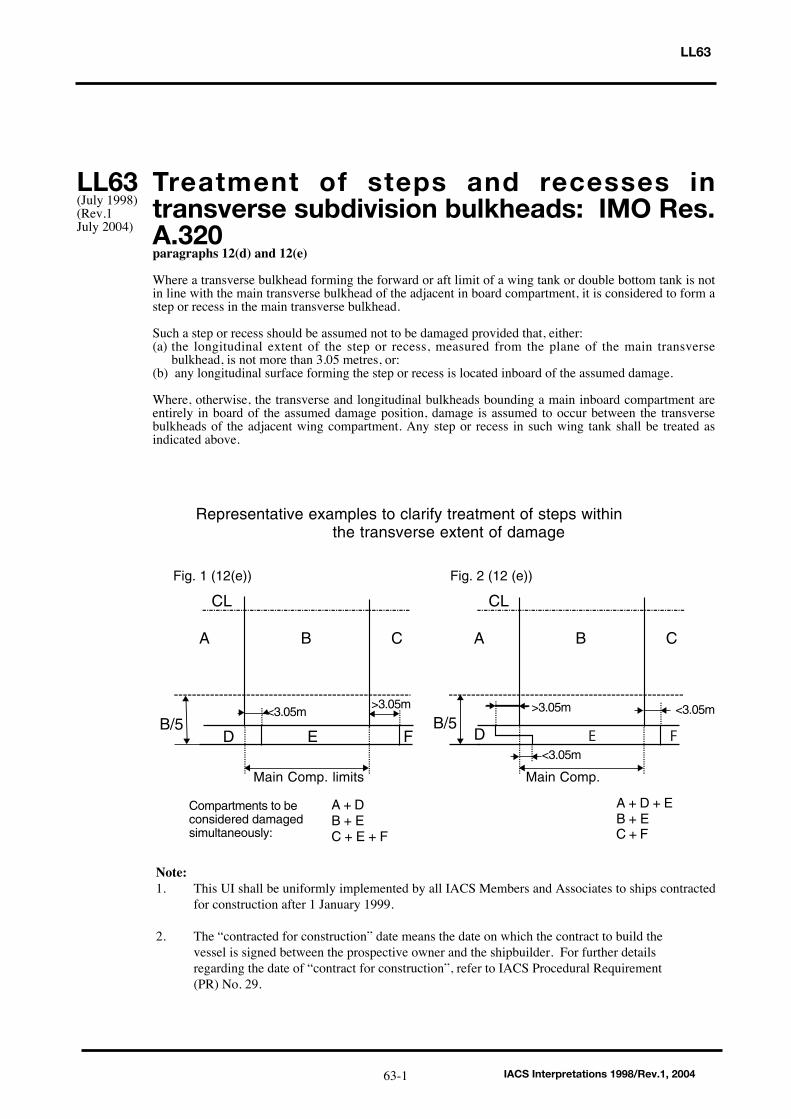
LL63
Treatment of steps and recesses intransverse subdivision bulkheads: IMO Res.A.320paragraphs 12(d) and 12(e)
Where a transverse bulkhead forming the forward or aft limit of a wing tank or double bottom tank is notin line with the main transverse bulkhead of the adjacent in board compartment, it is considered to form astep or recess in the main transverse bulkhead.
Such a step or recess should be assumed not to be damaged provided that, either:(a) the longitudinal extent of the step or recess, measured from the plane of the main transverse
bulkhead, is not more than 3.05 metres, or:(b) any longitudinal surface forming the step or recess is located inboard of the assumed damage.
Where, otherwise, the transverse and longitudinal bulkheads bounding a main inboard compartment areentirely in board of the assumed damage position, damage is assumed to occur between the transversebulkheads of the adjacent wing compartment. Any step or recess in such wing tank shall be treated asindicated above.
LL63(July 1998)(Rev.1July 2004)
IACS Interpretations 1998/Rev.1, 200463-1
Representative examples to clarify treatment of steps within the transverse extent of damage
A + D + EB + E
B/5D E F
A B C
CL
Main Comp. limits
Fig. 1 (12(e))
A + DB + EC + E + F
Main Comp.
B/5D
A B C
CL
Fig. 2 (12 (e))
<3.05m
>3.05m>3.05m<3.05m
Compartments to beconsidered damagedsimultaneously:
<3.05m
C + F
E F
Note:1. This UI shall be uniformly implemented by all IACS Members and Associates to ships contracted
for construction after 1 January 1999.
2. The “contracted for construction” date means the date on which the contract to build the vessel is signed between the prospective owner and the shipbuilder. For further details regarding the date of “contract for construction”, refer to IACS Procedural Requirement (PR) No. 29.
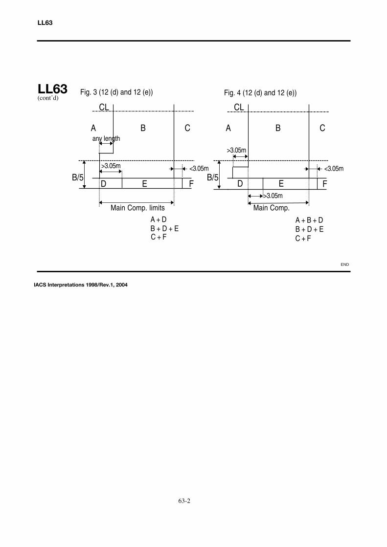
LL63
LL63(cont’d)
FB/5
D E F
A B C
CL
Main Comp. limits
B/5D E
A B C
CL
Main Comp.
Fig. 3 (12 (d) and 12 (e))
A + B + DB + D + E
A + DB + D + E
any length
>3.05m
>3.05m
>3.05m
Fig. 4 (12 (d) and 12 (e))
<3.05m<3.05m
C + F C + F
63-2
IACS Interpretations 1998/Rev.1, 2004
END

________________________
Note: 1. This Unified Interpretation is to be uniformly implemented by all Members and Associates from1 July 1999, unless otherwise instructed by a Flag State.
2. Changes introduced in Rev.3 are to be uniformly implemented by IACS Members and Associates from 1 January 2002.
3. Changes introduced in Rev.4 are to be uniformly implemented by IACS Members and Associate from 1 January 2006.
LL64
Non-weathertight hatch covers above superstructure deck
(Load Line Convention 1966 Regulations 2 (5) and 14(2))
The requirements for coaming height and weathertightness of hatch covers located above thesuperstructure deck are left to the satisfaction of the flag Administration by Regulations 2 (5) and 14(2)of the Load Line Convention. Exposed coamings and hatch covers situated above the second tier of thesuperstructure, or equivalent, or above the third tier, or equivalent, in the forward quarter of the ship'slength, may be regarded to be above the superstructure deck in the application of 14(2). Non-weathertight covers in these locations may be accepted subject to the approval of the flag Administrationand conditional upon the following :
1 Their acceptance should be limited to use on container ships.
2 They may be fitted to hatchways located on weatherdecks which are at least two standardsuperstructure heights above an actual freeboard deck or an assumed freeboard deck from which afreeboard can be calculated which will result in a draught not less than that corresponding to thefreeboard actually assigned. Where any part of a hatchway is forward of a point located one quarter ofthe ship's length (0.25L) from the forward perpendicular, that hatchway is to be located on a weatherdeckat least three standard superstructure heights above the actual or assumed freeboard deck. It is to benoted that the assumed freeboard deck is used only for the purpose of measuring the height of the deckon which the hatchways are situated and may be an imaginary, or virtual deck and in this case is not to beused for the actual assignment of freeboard. The vessels freeboard is to be assigned from an actual deck,designated as the freeboard deck, which is to be determined in accordance with the Convention andLL39.
3 The hatchway coamings should be not less than 600 mm in height.
4 The non-weathertight gaps between hatch cover panels should be considered as unprotectedopenings with respect to the requirements of intact and damage stability calculations. They should be assmall as possible commensurate with the capacity of the bilge system and expected water ingress, and thecapacity and operational effectiveness of the fire-fighting system and, generally, should not exceed 50mm.
5 Labyrinths, gutter bars, or equivalents should be fitted proximate to the edges of each panel inway of the gaps to minimise the amount of water that can enter the container hold from the top surface ofeach panel.
6 Scantlings of the hatch cover panels are to be equivalent to those for weathertight covers and inaccordance with the applicable requirements of UR S21 and UI LL70. The details on the securingarrangements to the vessel’s support structure and coamings are provided in IACS Recommendation No.14.
LL64(December1998)(Rev.1,March 1999)(Rev.2June 2000)(Rev.3July 2001)(Rev.4July 2005)
IACS Interpretations 1998, Rev. 4 July 2005
▼
64-1
7. Bilge alarms should be provided in each hold fitted with non-weathertight covers. LL64(cont’d)
▼
LL64
▼
IACS Interpretations 1998, Rev. 4 July 2005
64-2
LL65
Page 1 of 1 IACS Int. 2000/Rev.1 2007
LL65(cont)
Ships with assigned or reassigned reducedfreeboards and intended to carry deck cargo(SOLAS, Chapter II-1, Regulation 4, footnotes .6 and .7)
“Cargo ships shown to comply with the following regulations may be excluded from theapplication of part B-1:
.6 Damage stability requirements of regulation 27 of the 1966 Load Lines Convention asapplied in compliance with resolutions A.320(IX) and A.514(13), provided that in the case ofcargo ships to which regulation 27(9) applies, main transverse watertight bulkheads, to beconsidered effective, are spaced according to paragraph (12)(f) of resolution A.320(IX),except ships intended for the carriage of deck cargo; and
.7 Damage stability requirements of regulation 27 of the 1988 Load Lines Protocol, exceptships intended for the carriage of deck cargo”.
General:
1. This UI pertains to ships intended to carry deck cargo and assigned or reassignedreduced freeboards in accordance with Regulation 27 of the International Conventionon Load Lines, 1966 (ICLL 1966) or the ICLL 1966 as amended by the 1988 Protocol.
2. In .6 and .7 of the footnotes to SOLAS Chapter II-1, Regulation 4, ships shown tocomply with ICLL 1966 Regulation 27 as applied in compliance with IMO Res. A.320and A.514, may be excluded from the application of SOLAS Chapter II-1 Part B-1,except if they carry deck cargo.
3. Therefore ships identified in item 1), above, shall:
a) according to the assigned reduced freeboards, comply with damage stabilityrequirements of Regulation 27 of ICLL 1966 and the 1988 Protocol to the ICLL1966; and
b) according to the intended deck cargo capacity, be provided with the limitingGM or KG curve required by SOLAS Chapter II-1, Regulation 5-1.4 incompliance with the probabilistic damage stability analysis of SOLAS ChapterII-1 Part B-1.
4. The KG used for demonstrating compliance with the criteria in 3 a) shall be the sameas that used for the criteria in 3 b) at the deepest subdivision load line.
Note:
1. This UI LL 65 is to be uniformly implemented by IACS Members and Associatesfrom 1 July 2001.
2. Revision 1 is to be uniformly implemented by IACS Members and Associates from1 January 2009.
LL65(June2000)(Rev.1June2007)
End ofDocument

Hatch Cover Stress/Deflection Calculation(Res. MSC.143(77), 2005 LL Protocol Regulation 16(5) (a) & (b))
Regulation 16 Hatchways closed by weathertight covers of steel or other equivalent materials
Hatch cover minimum design loads
(5) All hatch covers shall be designed such that:
(a) the product of the maximum stress determined in accordance with the above loads and the factor of 1.25 does not exceed the minimum upper yield point strength of the material in tension and the critical buckling strength in compression;
(b) the deflection is limited to not more than 0.0056 times the span,
Interpretation
In the calculation of stress and deflection from the prescribed mass per unit area, thedesign pressure is to be determined by using a vertical acceleration equal to 1.0g.
Note: This UI LL 66 is to be uniformly implemented by IACS Members and Associates from 1 January 2005.
LL66(Oct2003)
LL66
IACS Interpretations 2003
▼▼
66-1

Endorsement of Certificates with the Date of Completion of the Survey on which theyare Based
“Resolutions MSC.170(79), MSC.171(79), MSC.172(79), MSC.174(79) throughMSC.179(79) and MSC.181(79) through MSC.187(79) require that the identifiedcertificates include the statement:
"Completion date of the survey on which this certificate is based: dd/mm/yyyy".
Interpretation
For application of the above resolutions, the following IACS UnifiedInterpretation applies:
The “Completion date of the survey on which this certificate is based”, is the date ofthe last initial/renewal survey visit on which all statutory and class items, required tobe surveyed, have been surveyed (regardless if they were found satisfactory or withminor deficiency).
Note:
1. This UI is to be uniformly implemented by IACS Members and Associates from 1 March 2004.
2. Revision 1 of this UI is to be uniformly implemented by IACS Members and Associates from 1 July 2006.
SC183(Nov 2003)(Rev.1, Nov.2005)
LL67(Nov 2003)(Rev.1, Nov.2005)
MPC10(Nov 2003)(Rev.1, Nov.2005)
LL67
IACS Interpretations 2003/Rev.1 200567-1
▼▼

LL68
▼
Position of Freeboard Deck on FloatOn/Float Off Barge Carriers(Regulation 3(9))
Reg.3(9):
“Freeboard Deck. The freeboard deck is normally the uppermost complete deckexposed to weather and sea, which has permanent means of closing all openings inthe weather part thereof, and below which all openings in the sides of the ship arefitted with permanent means of watertight closing. In a ship having a discontinuousfreeboard deck, the lowest line of the exposed deck and the continuation of that lineparallel to the upper part of the deck is taken as the freeboard deck. At the option ofthe owner and subject to the approval of the Administration, a lower deck may bedesignated as the freeboard deck provided it is a complete and permanent deckcontinuous in fore and aft direction at least between the machinery space and peakbulkheads and continuous athwartships. When this lower deck is stepped the lowestline of the deck and the continuation of that line parallel to the upper part of the deck istaken as the freeboard deck. When a lower deck is designated as the freeboard deck,that part of the hull which extends above the freeboard deck is treated as asuperstructure so far as concerns the application of the conditions of assignment andthe calculation of freeboard. It is from this deck that the freeboard is calculated.”
Interpretation:
1. Float On/Float Off Barge Carriers are designed to be ballasted such that the bottom of their cargo space(s) (well deck) submerges below the waterline to allow barges being floated in and out.
2. If such a ship is fitted with weathertight closures for the cargo space(s) and a watertight enclosure at the stern, the uppermost complete deck may be taken as the freeboard deck.
3. If such a ship is not fitted with weathertight closures for the cargo space(s) or a watertight enclosure at the stern, the well deck shall be taken as the freeboard deck, while buoyant spaces above may be considered as superstructures in accordance with UI LL 15 or 88 Prot. Reg. 34(1).
4. If such a ship is not fitted with weathertight closures for the cargo space(s) but has a watertight enclosure at the stern, the uppermost complete deck may bet aken as the freeboard deck provided that:
- the structure of the freeboard deck complies with the requirements of LL39;
- the calculated freeboard is corrected for any missing buoyancy above the well deck in accordance with LL48, and
- a satisfactory safety level at the resulting draught is demonstrated according to alternative concepts.
Note: This UI is to be uniformly implemented by IACS Members and Associates from 1 April 2005.
LL68(May 2004)
▼
IACS Interpretations 200468-1

LL69
▼
Interpretation to 1966 ICLL Reg. 27
Reg.27 of ICLL 1966: IMO Res. A.320 paragraph 12:
“Damage Assumptions
(12) The following principles regarding the character of the assumed damage apply:
(a) The vertical extent of damage in all cases is assumed to be from the base lineupwards without limit.
(b) The transverse extent of damage is equal to B/5 or 11 5 metres (37.7 feet), which ever is the lesser, measured inboard from the side of the ship perpendicularly to the centre line at the level of the summer load water line.
(c) If damage of a lesser extent than specified in sub paragraphs (a) and (b) of thisparagraph results in a more severe condition, such lesser extent shall be assumed.
(d) Except where otherwise required by paragraph (10)(a) the flooding shall be confined to a single compartment between adjacent transverse bulkheads provided the inner longitudinal boundary of the compartment is not in a position within the transverse extent of assumed damage. Transverse boundary bulkheads of wing tanks, which do not extend over the full breadth of the ship shall be assumed not to be damaged, provided they extend beyond the transverse extent of assumed damage prescribed in sub paragraph (b) of this paragraph.
If in a transverse bulkhead there are steps or recesses of not more than 3.05 metres (10 feet) in length located within the transverse extent of assumed damage as defined in sub-paragraph (b) of this paragraph, such transverse bulkhead may be considered intact and the adjacent compartment may be floodable singly If, however, within the transverse extent of assumed damage there is a step or recess of more than 3.05 metres (10 feet) in length in a transverse bulkhead, the two compartments adjacent to this bulkhead shall be considered as flooded. The step formed by the after peak bulkhead and the after peak tank top shall not be regarded as a step for the purpose of this Regulation.
(e) Where a main transverse bulkhead is located within the transverse extent ofassumed damage and is stepped in way of a double bottom or side tank by morethan 3.05 metres (10 feet), the double bottom or side tanks adjacent to the stepped portion of the main transverse bulkhead shall be considered as flooded simultaneously. If this side tank has openings into one or several holds, such as grain feeding holes, such hold or holds shall be considered as flooded simultaneously. Similarly in a ship designed for the carriage of fluid cargoes, if a side tank has openings into adjacent compartments, such adjacent compartments shall be considered as empty and flooded simultaneously. This provision is applicable even where such openings are fitted with closing appliances, except in the case of sluice valves fitted in bulkheads between tanks and where the valves are controlled from the deck Manhole covers with closely spaced belts are considered equivalent to the unpierced bulkhead except in the case of openings in topside tanks making the topside tanks common to the holds.
LL69(May2004)
IACS Interpretations 200469-1
Note: This UI is to be uniformly implemented by IACS Members and Associates from 1 April 2005.

(f) Where the flooding of any two adjacent fore and aft compartments is envisagedmain transverse watertight bulkheads shall be spaced at least 1/3L2/3 or 14.5 metres (0.495L2/3 or 47.6 feet), whichever is the lesser, in order to be considered effective. Where transverse bulkheads are spaced at a lesser distance, one or more of these bulkheads shall be assumed as non-existent in order to achieve the minimum spacing between bulkheads.”
Interpretation:
Treatment of the volume of the forecastle, which is located over the foremost cargo holdfor damage stability calculation in accordance with Reg.27 of ICLL 1966: IMO Res.A.320 paragraph 12.
In the case where the forecastle overlaps foremost cargo hold, provided the forecastlebulkhead is not more than 3.00m aft of the forward bulkhead of the hold and the deckforming the step in way is watertight, then the bulkhead will be considered ascontinuous and not subject to damage.
▼ ▼
LL69cont
IACS Interpretations 2004
LL69
69-2

Corrosion Margin for Hatch Cover DesignReg. 16 (5)(d), amendments to the Protocol of 1988 relating to the InternationalConvention on Load Lines, 1966 (Res. MSC. 143(77))
Regulation 16 (5) (d) reads:
Hatchways closed by weathertight covers of steel or other equivalent material
All hatch covers shall be designed such that:
(a) the product of the maximum stress determined in accordance with the above loads and the factor of 1.25 does not exceed the minimum upper yield point strength of the material in tension and the critical buckling strength in compression;
(b) the deflection is limited to not more that 0.0056 times the span;
(c) steel plating forming the tops of covers is not less in thickness that 1% of the spacing of stiffeners or 6 mm if that be greater; and
(d) an appropriate corrosion margin is incorporated.
Interpretation
The “appropriate corrosion margin” for hatch covers of cargo holds in position 1 and 2and above, defined as the corrosion addition ts which is to be added to the netthickness tnet required by (a), (b) and (c) is:
1. for Bulk Carriers, Ore Carriers and Combination Carriers, as defined in UR Z11.2:
- single skin hatch covers, a corrosion addition ts = 2.0 mm for all plating and stiffeners;
- double skin hatch covers, a corrosion addition ts = 2.0 mm for top and bottomplating and ts = 1.5 mm for the internal structure.
2. for other vessels:
- single skin hatch covers, a corrosion addition ts = 2.0i) mm for all plating and stiffeners;
- double skin hatch covers, a corrosion addition ts = 1.5i) mm for top and bottom plating and ts = 1.0 mm for the internal structure.
i) Corrosion addition ts = 1.0 mm for the hatch covers in way of cellular cargo holds intended for containers.
LL70(Jan2005)
LL70
IACS Interpretations 200570-1
The above corrosion margins have been defined based on the assumption thatcorrosion protection and renewals as given in UR S21.6.1 is complied with for all shiptypes subject to regulation 16 (5) (d) of the 1988 Load Line Protocol.
For corrosion addition ts = 1.0 mm it is assumed that the thickness for steel renewal istnet and the thickness for coating or annual gauging is tnet + 0,5 mm.
Note: This UI LL70 is to be uniformly implemented by IACS Members and Associates on ships constructed (i.e. keel laid) from 1st January 2005.
END
LL70(C’td)
LL70
70-2
IACS Interpretations 2005
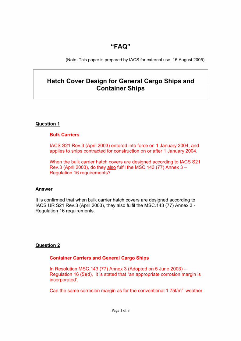
Page 1 of 3
“FAQ”
(Note: This paper is prepared by IACS for external use. 16 August 2005).
Hatch Cover Design for General Cargo Ships and
Container Ships
Question 1
Bulk Carriers
IACS S21 Rev.3 (April 2003) entered into force on 1 January 2004, and applies to ships contracted for construction on or after 1 January 2004.
When the bulk carrier hatch covers are designed according to IACS S21 Rev.3 (April 2003), do they also fulfil the MSC.143 (77) Annex 3 – Regulation 16 requirements?
Answer It is confirmed that when bulk carrier hatch covers are designed according to IACS UR S21 Rev.3 (April 2003), they also fulfil the MSC.143 (77) Annex 3 - Regulation 16 requirements. Question 2
Container Carriers and General Cargo Ships
In Resolution MSC.143 (77) Annex 3 (Adopted on 5 June 2003) – Regulation 16 (5)(d), it is stated that “an appropriate corrosion margin is incorporated’.
Can the same corrosion margin as for the conventional 1.75t/m2 weather
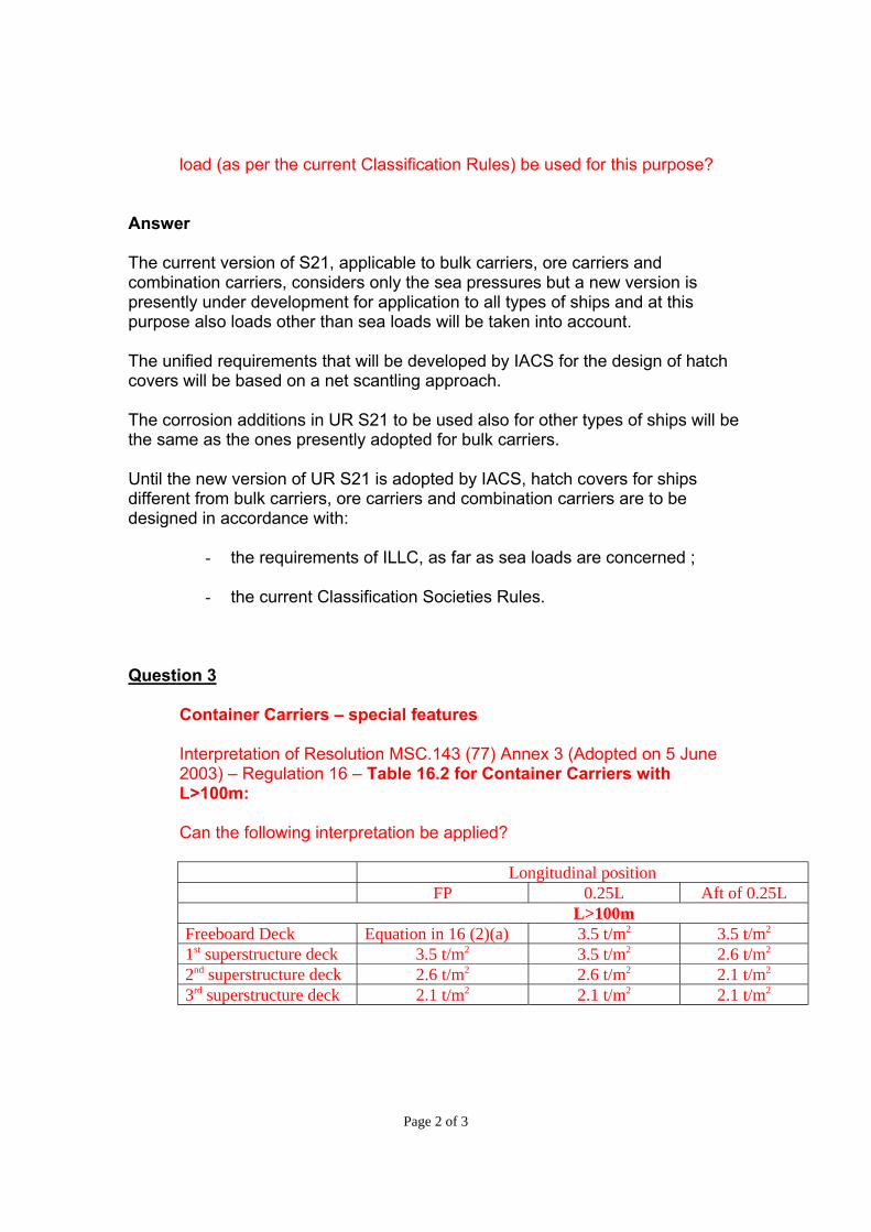
Page 2 of 3
load (as per the current Classification Rules) be used for this purpose?
Answer The current version of S21, applicable to bulk carriers, ore carriers and combination carriers, considers only the sea pressures but a new version is presently under development for application to all types of ships and at this purpose also loads other than sea loads will be taken into account. The unified requirements that will be developed by IACS for the design of hatch covers will be based on a net scantling approach. The corrosion additions in UR S21 to be used also for other types of ships will be the same as the ones presently adopted for bulk carriers. Until the new version of UR S21 is adopted by IACS, hatch covers for ships different from bulk carriers, ore carriers and combination carriers are to be designed in accordance with:
- the requirements of ILLC, as far as sea loads are concerned ;
- the current Classification Societies Rules. Question 3
Container Carriers – special features
Interpretation of Resolution MSC.143 (77) Annex 3 (Adopted on 5 June 2003) – Regulation 16 – Table 16.2 for Container Carriers with L>100m: Can the following interpretation be applied?
Longitudinal position
FP 0.25L Aft of 0.25L L>100m
Freeboard Deck Equation in 16 (2)(a) 3.5 t/m2 3.5 t/m2 1st superstructure deck 3.5 t/m2 3.5 t/m2 2.6 t/m2 2nd superstructure deck 2.6 t/m2 2.6 t/m2 2.1 t/m2 3rd superstructure deck 2.1 t/m2 2.1 t/m2 2.1 t/m2

Page 3 of 3
Answer The design loads can be reduced from 2,6 t/m2 to 2,1 t/m2, as proposed above, for locations other than positions 1 and 2, as defined in ILLC. The following considerations have been given for accepting a load reduction:
- Position 2 is defined in the Amendments to the Protocol of 1988 with respect to the exposed superstructure decks.
- The meaning of "located at least one (or two, when forward of 0,25L
from forward perpendicular) standard height of superstructure above the freeboard deck", relevant to the "position 2" definition, should be interpreted as: decks of superstructures having height less than one (two) standard height(s) of superstructure are to be considered as being in "position 1".
In conclusion, locations more than two (or three, when forward of 0,25L from forward perpendicular) standard height of superstructure above the freeboard deck are not position 2 and the design loads in these locations may be reduced with respect to those specified in ILLC. Question 4
To determine the hatch cover location, can we use the “assumed freeboard deck” as defined in IACS UI LL64?
Answer It is confirmed that LL 64 is to be used to determine the hatch cover location.
END
Similar stage of construction (1966 ILLC, Article 2 (6))(amended LL Protocol 1988, regulation 2, paragraphs (7) and (8))
1966 ILLC, Article 2(6):
New ship means a ship the keel of which is laid, or which is at a similar stage ofconstruction, on or after the date of coming into force of the present Convention foreach Contracting Government.
Amended 1988 LL Protocol, regulation 2, paragraphs (7) and (8):
(7) Unless expressly provided otherwise, the regulations of this Annex shall apply to ships the keels of which are laid or which are at a similar stage of construction onor after 1 January 2005.
(8) For ships the keels of which are laid or which are at a similar stage of construction before 1 January 2005, the Administration shall ensure that the requirements which are applicable under the International Convention on Load Lines, 1966, as modified by the Protocol of 1988 relating thereto, adopted by the International Conference on Harmonized System of Survey and Certification, 1988, are complied with.
Interpretation:
The term “similar stage of construction” means the stage at which:
- construction identifiable with a specific ship begins; and
- assembly of that ship has commenced comprising at least 50 tonnes or oneper cent of the estimated mass of all structural material, whichever is less.
Note: This UI LL71 is to be uniformly implemented by IACS Members and Associate from 1 July 2005.
IACS Interpretations 200571-1
LL71
LL71(April 2005)
END
Interpretation to ICLL Regulation 27
Regulation
Regulation 27(3) reads:
A type "A" ship, if over 150 m in length, and designed to have empty compartmentswhen loaded to her summer load water line, shall be able to withstand the flooding ofany one of these empty compartments at an assumed permeability of 0.95, and remainafloat in a condition of equilibrium considered to be satisfactory by the Administration.In such a ship, if over 225 m in length, the machinery space shall be treated as afloodable compartment but with a permeability of 0,85.
Interpretation
Members apply resolution A.320(IX) when certifying ships of non 1988 Protocol Partiesunder regulations 27(3) of the 1966 ICCL.
Note:This UI is to be uniformly implemented by IACS Members and Associates to shipsconstructed on or after 1 January 2006.
▼
LL72(Sept 2005)
▼
IACS Interpretations 2005 72-1
LL72


![RNI Regn.No.- 54447/78 1978 Postal Reg. No. UA/NTL- 08 ... · RNI Regn.No.- 54447/78 LFkkfi r% 1978 Postal Reg. No. UA/NTL- 08/ 2018-20 l kIrkfgd ft Kkl k VsªMl Z ykyMkV jkM] eYyh](https://img.dokumen.tips/doc/110x75/5e9c3643c0c46d0bee7cc1a4/rni-regnno-5444778-1978-postal-reg-no-uantl-08-rni-regnno-5444778.jpg)