Embed Size (px)
Citation preview

INTERNATIONAL SCIENTIFIC CONFERENCE
CIBv 2010
12 – 13 November 2010, Braşov
A NEW CROSSING OF MUREŞ RIVER IN ARAD COUNTY
Dorel BOLDUŞ*, Radu BĂNCILĂ**, Bogdan BOLDUŞ***
* “Politehnica” University of Timişoara
** “Politehnica” University of Timişoara *** S.C. BB-CONS SRL Timişoara
.................................. Corresponding author: Dorel BOLDUŞ, E-mail: [email protected]
Abstract: This paper presents many constructive solutions studied for crossing the river Mures by road DJ 709E between the localities Pecica and Sanpetrul German in Arad County, western Romania. The bridge will be located in a protected area, as a natural park, so the design solutions and erection technologies are tailored conditioning. The infrastructure will be made by reinforced concrete and the superstructure by steel with steel-concrete composite deck slab. The paper explores five design alternatives for the static system: differently continuous beams, arches and cable-stayed structure and compares the costs and time of execution. Finally, we recommend the most cost effective solution.
Key words: road bridge, Mures river, multi span deck-plate continuous girder bridge, arched-trough bridge, cable-stayed bridge.
1. INTRODUCTION
County road DJ 709E connects the town of Pecica and the localities on the left bank of river Mureş, in Arad County: Sampetrul German, Secusigiu, Satu Nou (on DJ 682) and continuing toward the localities in Timiş County: Periam and the national road DN 69 Timisoara-Sannicolau Mare-Cenad, respectively the localities downstream the right bank: Semlac, Seitin, Nadlac (on DJ 709D). At the present moment the crossing of the river Mureş is done, for all the above mentioned localities, in difficult conditions and only for lightweight vehicles, by a floating bridge, manually manoeuvred.
.…. actually line of DJ709E
.…. new line of DJ709E ---- connection line ˙ SF bridge location (Vo)
˙ final location (V3)
Fig. 1 Aerial view of the bridge location Fig. 2 Bridge’s position in natural park area

Dorel BOLDUŞ, Radu BĂNCILĂ, Bogdan BOLDUŞ
154
Because of this fact, approximately 37,000 people (from the towns in Arad County) have to suffer. The only possibility of crossing the river on a road bridge in using the one in the town Arad, approximatively 25 km upstream, while downstream, the only place to cross would be the bridge in Mako, Hungary, about 55 km away. The intersection of DJ 709E and the river Mureş is located south-south-west of Pecica, in the river plane, close to the dam on the right bank
Presently, the floating bridge has two stations, about 30 m away from each other, one upstream, for the situation of deep water caused by prolonged floodings, and one station downstream, for shallow or normal water depth. The dam on the left bank is situated rather far from the minor bed, approximatively 850 m, and the county road being situated on the major bed.
2. CHARACTERISTICS OF THE PROJECT
2.1 Location of the bridge
After the discussions with the local authorities, following the analysis of the natural relief of the region and of the present route of the DJ 709E road it was decided that the bridge be located in the same area where the present floating bridge is, the heads of the new bridge would be established in the major bed on the left side and behind the dam protecting Pecica, on the right side.
The deviation of the county road to the south-south-west part of the Pecica outskirts and its connection with DJ 709C (County Road 709C) and DN 7 (National Road 7) will be studied in a separate paper. This new concept will help decongesting the traffic from the central area of the town and will facilitate the access to the road and the bridge for the inhabitants from the downstream towns - Semlac, Seitin, Igris etc. – as well as the transit from the Nadlac-Arad highway and DN 7/E 68 Nadlac-Arad. When choosing the location we considered the necessity to ensure the navigable span on the river Mureş. The bridge is designed for a service period of 100 years, during which further development of the region is expected. We also had in mind the connections between the upstream and downstream regions, done by roads that will ensure traffic free from any clearance or tonnage restrictions.
In order to establish and locate the bridge axis a topographic survey of the area was necessary as well as a preliminary geotechnical study, in order to determine the physical mechanical characteristics of the soil in the location.
As a result of the topographic survey of the terrain in the location area we saw that the best location – leading to the shorter bridge, which implies minimal alterations of the existing road, to less affect the natural environment and to allow the realization of the investment, in two distinctive stages – is at about 80 m upstream from the lower position of the present floating bridge.
The position of the bridge centre-line is marked on the annexed drawings [1], superimposed on a plan for aerial surveying of the site, in three additional locations from the original version V0, initially presented in SF to be the most economical version, called V1, V2 and V3 (figure 13).
2.2. Cross section
In conjunction with the road characteristics and with the prescription requirements and the technical design standards in force [2], [3], [4],[5] (national standards and EU standards) at the time of the study, the cross section of the bridge has been chosen so that it includes (fig.)
• two lanes with a width b = 3.00 m each and a widening due to the optical narrowing effect E0 = 0.5 m, resulting in carriage way c = 7.00 m;
• the space for the guard rail will be Sp = 0.50 m on each side; the guard rails installed will be concrete DELTA BLOCK-80AS-R type;
• cycling track with pc = 1.25 m in width on each side; • pedestrian sidewalks, having the width T = 0.75 m on each side, bordered by the
cycling track.

A new crossing of Mureş river in Arad County
155
2.5% 2.5%
250
188.
5
250250
Fig. 3 Typical cross section of the bridge deck
Under the bridge the Romanian type II navigable span is ensured on the river Mures, having the 5x40 m navigation rectangle (5.0 m height above the maximum quota of navigation and 40.0 m in width).
It also provides a space under the bridge for approx. 2.40 m above the ridge height of the embankment and thus, the necessary free space from the high waters is ensured (N.A.E. height).
2.3. Data on water and navigation
Mures river is currently not navigable but considering the expected life of the new bridge and the perspective of starting navigation, the design has taken into consideration the type II navigation span (5x40m navigation rectangle).
In order to establish the optimum solution the following preliminary data have been used: Maximum flow: 2440 mc/s Average flow: 184 mc/s The level of the bottom of the river bed (thalweg): +94.32m nMN (Black Sea level) Width of the river bed: 106.25m Water level (July 2009): +96.82m nMN Embankment heights: ~102.90m nMN left bank ~103.11m nMN right bank
3. CONSTRUCTIVE VARIANTS
3.1. Analysed constructive variants
Within the feasibility study six constructive variants were studied, having the most common and used construction variants: multi span deck-plate continuous girder bridge, with unequal or equal spans, arched trough bridge, cable-stayed bridge.
Following the bridge site analysis, correlated with the specific shape of minor bed - the deepest water being near the left shore and not to the middle as it would be ideal, it was found that in Variant 0 (after dividing into spans, according to the principle of the continuous beams economics – the marginal span in the range 0.7-0.8 of the current span) the navigation clearance cannot be provided and pier 1 will fall exactly on the water line in the deep water area, which leads to difficult working conditions and added cost. Because of this fact this variant was dropped.
a) Variant 1 : Deck-plate continuous girder structure, 5 equal spans: L = 5x70.0m =350m
7000 7000 7000 7000
-2,00-2,20
-1.50 -1.30-2.30 -2.30
-2.40-2.50
96.8296.82
99.97100.2399.25
100032700
101.40
7000
500
277
96.82
777
96.82
96.82
105.39
94.32
99.59
100
nivel maxim navigatie
101.80 N.A.E.
104.59 gabarit navigatie
105.59192 25 107.74nivel superior cale
103.11
167
Fig. 4 Elevation of Variant 1

Dorel BOLDUŞ, Radu BĂNCILĂ, Bogdan BOLDUŞ
156
Spans : 70.00+70.00+70.00+70.00+70.00 m Total bridge length : 350.00m Superstructure type: composite, 4 continuous beams with connectors and 24cm concrete slab Superstructure height : 208 cm beam on abutments/168 cm field beam /288 cm pier beam Construction height : min.=1.86 m; max.=3.06m Number of piers : 4 Total number of foundation pile (D=1008mm)/length: 82/1388m Surface of the bridge : 4200m2
b) Variant 2 : Main span arched trough and continuous deck plate-girder bridge, 4 unequal spans : L = 100.0m + 55.0m + 2x70.0m + 55.0m =350m
-2,00 -2,20-1.50 -1.30
-2.30 -2.30-2.40-2.50
96.8296.82
99.97100.23
103.11
99.25
101.40
124
5500 7000 7000 5500 1000090
103.11
500
277
96.82
777
105.39
94.32
99.59
143
nivel maxim navigatie
101.80 N.A.E.
104.59 gabarit navigatie
106.02107.74 nivel superior cale
700
P1
Fig. 5 Elevation of Variant 2
Spans : 100.00+55.00+70.00+70.00+55.00 m Total bridge length : 350m Superstructure type : main span Langer beam and composite deck/deck plate-girder bridge Superstructure height : arc =18.00m Construction height : 2.20/min.=1.86m;max.=3.06m Number of piers : 4 Total number of foundation pile (D=1008mm)//length : 93/1574m Surface of the bridge : 4337 mp
Fig. 6 Variant 2 – Structural arch scheme, and significant stress diagrams
A main span of 100 m was designed, over the minor bed on the water line. The span was covered with an arch superstructure with reinforcement beam and a cable-stayed structure (fig.6). The dimensions of the parabolic arch are: the span L=100 m and the spring chamber (elongation) H=18 m. The cables that support the reinforcement beam are placed 10 m away from each other, at every tenth of the span. The plan of the arches is placed behind the guard rails and has a 20° inclination from the vertical line. The sidewalks and the cycling tracks are built in bracket.
c) Variant 3 : Arched trough bridge, 3 equal spans and 50 m dam: L=3x100.0 = 300 m Total bridge length : 300.0m Spans : 100.00+100.00+100.00 m
490490
1336.88

A new crossing of Mureş river in Arad County
157
-2,00 -2,20-1.50 -1.30
-2.30 -2.30-2.40-2.50
96.8296.82
99.97100.2399.25
500
277
777
105 .90
143
nivel maxim navigatie
N .A.E.
gabar it navigatie
nivel super ior cale
P1
91.78
18.0
02.
00
15 Coloane fo rateD100, L=18.00m
Beton turnat subapa
Blocaj piatra sparta
Aparat de reazemmobil
8.00
4.00
1:2
Scara acces
Aparat de reazemfix
14.0
02.
009.
49
6.00
0.50 4.70 0.80
80.42
94.42
Beton turnat subapa
11 Co loane forateD100, L=14.00m
73.78
100.65 101.30 100.65
C2
6.00
14.0
02.
006.
49
4.70
2.401.20
1.61
98.91
84.91
11 Coloane forateD100, L=14.00m
106.90
302.60
12.0
3
95.18
18.0
02.
00
15 Co loane forateD100, L=18.00m
Beton turnat subapa
Bloca j piatra sparta
8.00
77.18
8.63
P2
S cara acces
Fig. 7 Elevation of Variant 3
Superstructure type : Langer beam and composite deck Number of piers : 2 Total number of foundation pile (D=1008mm)/length : 66/1076 Surface of the bridge : 3011 m2 A bridge with three equal spans of 100 m each has been designed. The same arch structure as
in main span-variant 2 was used. The sidewalks and the cycling tracks are built in bracket. d) Variant 4 : One-tower cable-stayed bridge by a total length L=350 m
Bridge with central pylon, H=60 m high and with three bracing wires symmetrically set as compared to the middle of the bridge (Fig. 8). Eight spans are thus realized. The bracing is made in twofold plan. An A shaped pylon has been chosen.
Fig. 8 Elevation of Variant 4
Spans : 42.00 + 44.00 + 44.00 + 45.00 + 45.00 + 44.00 +44.00+ 42.00 m Superstructure type : steel box girder with orthotropic plate Superstructure height : 2080mm Pylon height : 60.00m Construction height : 2.26m Number of piers : 1 Total number of foundation pile (D=1008mm)/length : 97/1778m Surface of the bridge : 4200 m2
Fig. 9 Structural scheme and significant stress diagrams of Variant 4
Besides the outstanding aesthetic aspect the bridge has the advantage of having one single pier, in the centre of the major bed.
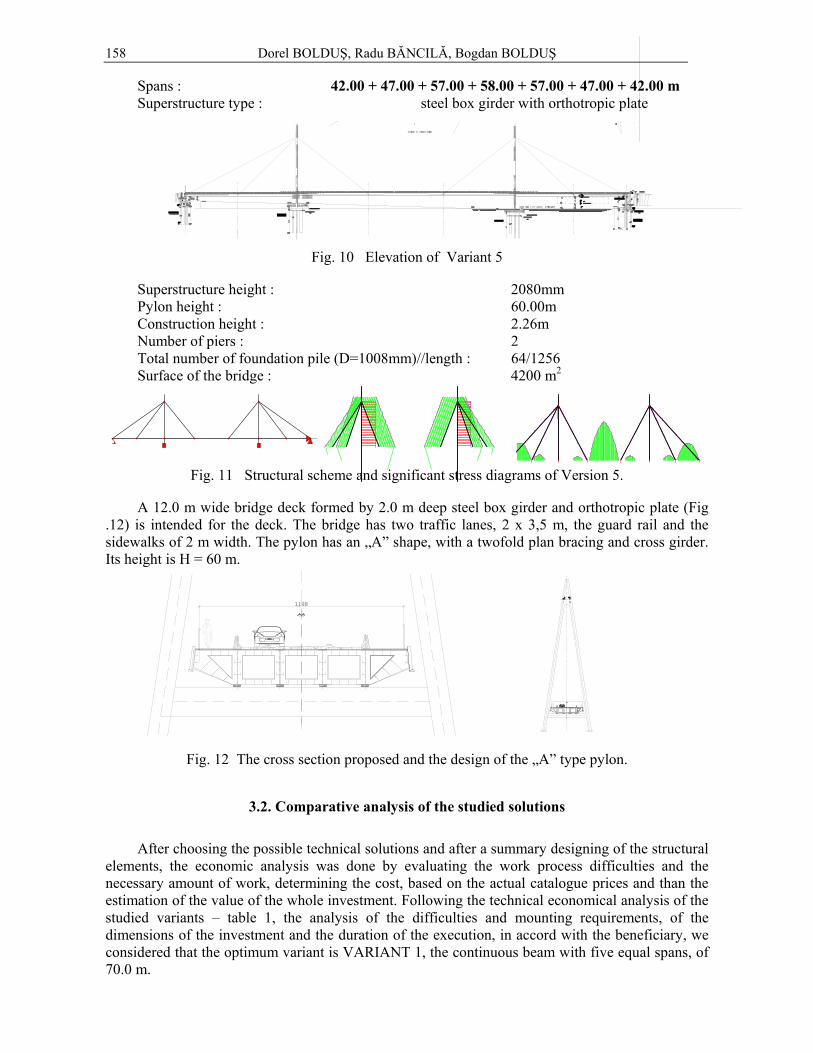
e) Variant 5. Two-tower cable-stayed bridge by a total length L=350 m Two tower bridge, symmetrically set and having 6 bracing wires. Seven spans are thus
obtained. (Fig. 10). The twofold bracing for the pylon was chosen to be A shaped. This solution asks for two towers to be placed in the river bed. The structure is aesthetical and gives the impression of a very slim structure. The same superstructure type as Variant 4 was chosen.
Dorel BOLDUŞ, Radu BĂNCILĂ, Bogdan BOLDUŞ
158
Spans : 42.00 + 47.00 + 57.00 + 58.00 + 57.00 + 47.00 + 42.00 m Superstructure type : steel box girder with orthotropic plate
Fig. 10 Elevation of Variant 5
Superstructure height : 2080mm Pylon height : 60.00m Construction height : 2.26m Number of piers : 2 Total number of foundation pile (D=1008mm)//length : 64/1256 Surface of the bridge : 4200 m2
Fig. 11 Structural scheme and significant stress diagrams of Version 5.
A 12.0 m wide bridge deck formed by 2.0 m deep steel box girder and orthotropic plate (Fig .12) is intended for the deck. The bridge has two traffic lanes, 2 x 3,5 m, the guard rail and the sidewalks of 2 m width. The pylon has an „A” shape, with a twofold plan bracing and cross girder. Its height is H = 60 m.
2.5% 2.5%
1198
2. 5% 2.5 %
1198
Fig. 12 The cross section proposed and the design of the „A” type pylon.
3.2. Comparative analysis of the studied solutions
After choosing the possible technical solutions and after a summary designing of the structural
elements, the economic analysis was done by evaluating the work process difficulties and the necessary amount of work, determining the cost, based on the actual catalogue prices and than the estimation of the value of the whole investment. Following the technical economical analysis of the studied variants – table 1, the analysis of the difficulties and mounting requirements, of the dimensions of the investment and the duration of the execution, in accord with the beneficiary, we considered that the optimum variant is VARIANT 1, the continuous beam with five equal spans, of 70.0 m.

A new crossing of Mureş river in Arad County
159
TABLE 1 Comparative characteristics and prices of the bridge’s studied variants
VALUES, without VAT with VAT
Spec.PRICE
Surf
ace
C+M bridge
Invest- ment
Invest- ment
Construction variant
Spans No. and
L(m)
No.
of p
iers
(mp) 1000 RON 1000RON/1000 €
1000RON/1000 €
total €/mp
1.
2. 1. Composite - GIPCS*
70.00 70.00 70.00 70.00
-2,00 -2,20-1.50 -1.30
-2.30 -2.30-2.40-2.50
96.8296.82
99.97100.23
10.00
101.40
70.00
5.00
2.77
96.82
7.77
105.12 105.39
94.32
99.59
1.19
nivel maxim navigatie
101.80N.A.E.
104.59gabarit navigatie
105.78107.87
103.11
105.63105.63105.12
93.83
95.53
97.02
91.68
108.02
2.48
P1P2
P3P4C1
14.0
02.
008.
00
6.00
0.50 4.70 0.80
8.00
18.0
02.
0011
.44
2.00
1.43
18.0
0
8.00
0
14.0
02.
004.
99
70
40
4.00
1:2
2.00
18.0
0
2.00
18.0
0
15 Coloane forateD100, L=18.00m
9.81
6.09
Beton turnat subapa
Blocaj piatra sparta
15 Coloane forateD100, L=18.00m
Beton turnat subapa
Blocaj piatra sparta
15 Coloane forateD100, L=18.00m
Beton turnat subapa
Blocaj piatra sparta
15 Coloane forateD100, L=18.00m
Blocaj piatra sparta
Aparat de reazemmobil
Aparat de reazemmobil
Aparat de reazemmobilAparat de reazem
mobilAparat de reazem
fix
Indicatorul D1Indicatorul luminos D1
Scara acces
73.68
77.40
75.83
77.53
79.02
95.40
Beton turnat subapa
11 Coloane forateD100, L=14.00m
5 x 70m 4 4200 23000,-
26778/ 6341
31672/ 7500 1786
2. Composite - Arch CJ** + GIPCS*
-2,00-2,20
-1.50 -1.30-2.30 -2.30
-2.40-2.50
96.8296.82
99.97100.2399.25
101.40
7000
103.11
500
277
96.82
777
105.90
94.32
99.59
143
nive l maxim navigatie
101.80 N.A.E.
104.59 gabari t navigatie
106.02107.74 nive l s uperior cale
P1
91.78
18.0
02.
0012
.03
15 Coloane forateD100, L=18.00m
Beton turnat subapa
Blocaj piatra sparta
Aparat de reazemmobil
8.00
93.83
P2
2.00
18.0
08.
61
15 Coloane forateD100, L=18.00m
Beton turnat subapa
Aparat de reazemmobil
76.21
4.00
1:2
Scara acces
Aparat de reazemfix
14.0
02.
009.
49
6.00
0.50 4.70 0.80
80.42
94.42
Beton turnat subapa
11 Coloane forateD100, L=14.00m
91.78
93.83104.82
95.91
P3
2.00
6.91
18.0
0
15 Coloane forateD100, L=18.00m
Beton turnat subapa
Blocaj piatra sparta
Aparat de reazemmobil
77.91
104.82
97.29
P4
8.00
2.00
18.0
05.
53
15 Coloane forateD100, L=18.00m
Aparat de reazemmobil
79.30
Blocaj piatra sparta
55.00 70.00 70.00 55.45 100.45
C2
6.00
14.0
02.
005.
99
4.70
2.401.20
1.61
97.91
83.91
11 C oloane forateD100, L=14.00m
105.90
350.90
105.90
1 x 100m 55+2x70+55 4 4337 26647,-
30992/ 7339 36658/
8681 2002
3. Composite deck - 3 Archs – CJ**
-2, 00-2,20
-1.50 -1.30-2. 30
-2.30-2.40-2.50
96 .8296.82
99.97100.2399.25
500
277
777
105.90
143
nivel maxim navigatie
N.A.E.
gaba rit navigatie
n ivel superio r cale
P1
91.78
18.
002.
00
1 5 Coloan e forateD100, L=18.00m
Beton turnat subapa
Blo caj piatra sparta
Aparat de reazemmobil
8 .00
4.00
1:2
S ca
A parat de reazemfix
14.0
02.
009.
49
6.00
0.50 4.70 0.80
80.42
94.42
B eton turn aapa
11 Coloane fo rD100, L=14.00
73.78
C2
6.00
14.
002.
006.
49
4 .70
2 .401 .20
1.61
98.91
8 4.91
1 Coloan e forateD100, L=14.00m
106.90
12.0
3
95.18
18.0
02.
00
15 Co loane forateD100, L=18.00m
Beton turnat subapa
Blocaj piatra sparta
8.00
77.18
8.6
3 P2
S cara acces
3 x 100m 2 3011 32206,-
37415/ 8860
44258/ 10481 3481
4. Cable-stayed 1 central tower multi box-girder+orthotropic plate
de exploatare 2x 175m 4 4200 31196,-
36248/ 8548 42878/
10154 2418
5. Cable-stayed 2 symmetrical towers multi box-girder+orthotropic plate
89+172+89m 2 4200 29840,-
34682/ 8123 41025/
9715 2313
*GIPCS = Plain girder deck bridge; **CJ= bottom-road; (BNR quotation /09.01.2009 : 1€ = 4.22 RON)
4. CHOOSING THE FINAL VARIANT
At the moment when the necessary approvals, in order to authorize the new construction, were
obtained it was discovered that part of the location chosen for the bridge was private property and had to be expropriated. Due to the fact that in Romania the expropriation procedures are difficult, costly and slow, we have studied other bridge layout (figure 13), respectively three new site position, named V1, V2 and V3, downstream from initial location named V0 in SF. (highlighted in red on the figure 1). Finally it was decided, in agreement with the beneficiary, that the location of the bridge be moved downstream from the floating bridge, so that it would be exclusively on public terrain. Location B was chosen (highlighted in blue on the figure 1), with the following technical alterations:
• Execution of an skew bridge (83º skew), having the total length of 444,0 m, with six equal spans of 74,0 m and the total surface of the bridge of 5328 m2 ;
• The Pecica abutment would exceed the dam and would be connected with the future alignment of the County Road DJ 709E, which will bypass the town Pecica;

Dorel BOLDUŞ, Radu BĂNCILĂ, Bogdan BOLDUŞ
160 • The new trace of County Road DJ 706E, on the left bank in order to connect the new
position of bridge.
DIG
DIG
DIG
Drum de exploatare
Drum de exploatare
Drum de exploatare
Padure - Tufaris
Pe aceasta linie profilul
Drum de exploatare Drum de exploatarePlatforma Betonata
Padure - Tufaris
Padure - Tufaris
Padure - Tufaris
Padure - Tufaris
Padure - Tufaris
100,19
Raul Mures
99.99
100.08
23
99.64
23
99.92
499.83
499.82
9.95
4100.37
4100.38
4100.27
23
99.7123
100.13
1
100.45
9.95
4-31
4
1
100.45
25
98.34
25
98.29
21
98.47
21
103.09
31
102.9513
102.70
10
103.12
31
103.13
31
98.48
4100.31 23
100.31
4100.46
23
100.12
1
100.42
40
100.3240
100.35
4099.92
40
99.79
40
98.3740
98.51
40
97.9740
97.93 31
96.72
8
100.38
8
100.568100.53 8
100.61
4100.09
4
100.10
1
100.42
31103.10
31
103.02
1100.22
4100.48
4100.43
4100.36
4
99.164
99.24
31
99.99
31
97.94
31
97.01
31
96.94
1100.20
31
96.92
31
96.94
31
96.88
897.00
31
96.96 4
96.964
96.90 31
96.91
1100.23
4
100.31
4100.19
4100.26
4100.08
4100.28
4
100.34
4
100.44
4100.39
4
100.43
4103.19 4
103.11 31
103.11
4
103.11
1100.22
4100.12
4100.21
4100.31
4100.38
4100.21
499.97
499.24
25
97.35
499.26
4
97.50497.54
46
96.82
46
96.82
497.25
497.38 46
96.84
23
97.108
97.14
25
96.83
4
97.22
497.27
497.30
497.27
8
97.29
46
96.82
46
96.84
4
97.62
497.85
199.49
4
100.28
4
100.11
4
99.52
4
99.38
4
98.89499.05
23
99.70
23
99.34
23
99.15 899.15
199.48
3101.45
199.72
31
25
97.69
25
97.29
499.01 4
99.14
46
96.8046
96.81
4696.85 46
96.82
46
96.81 46
96.7946
96.79
4
100.32
4100.19
46
96.81
46
96.79
46
96.81
46
96.79
25
98.00
199.74
96.86
4100.39
1100.24
4100.22
4
100.19
4100.26
4100.25
4
100.42
4100.51
4100.44
4100.39
4100.38
4
100.39
96.92 31
70.0
0
7 0. 00
70. 00
70.0
0
70. 00
1 :2
35 0
. 00
1 :2
Pro t ec ti a p ile lo r
Bl o ca j pi at ra s p a rta
Dr um
p i et o na l s i pi st a pe n tr u ci cli st i
Dre n
Pa ra p e ti
Tal uz pe r ea t
SAMPETRU G
ERMAN
PEC ICA
S car a ac ce s
Sca ra ac ce s
D re n
Tal uz p e r ea t
Sca
ra a
c ces
Sc ara
acc es
1: 2
1 :2
Pro te c tia pi le lo r
Blo c a j p ia t ra s p ar ta
Pro te c ti a p ile lo r
Blo ca j p ia tra sp a rt a
Pro te c tia pi le lo r
Blo c a j p ia t ra s p a rta
96.92 31
70 . 00
70 . 00
70.0
0
7 0 .0 0
7 0 .00
350 .0 0
Pr otec tia p ile lor
Bloc aj p iat ra s par ta
D rum piet onal s i p is ta pentr u c ic lis ti
D ren
Par apeti
S AMPE
TRU GE RM
AN
P EC IC A
Dr en
Pr otec tia p ile lor
Bloc aj p iat ra spar ta
Protec t ia p il el or
Bl ocaj p iatr a s part a
Pr otec ti a p ile l or
Bloc aj p i at ra s par ta96.92 31
70.00
70.00
70. 00
140. 00
70. 00
420. 0
0
Pr ot ecti a p ilel or
Blo ca j p iat ra spar ta
D rum pie ton al si pi st a pe ntr u cicl isti
D ren
P ar apeti
SAMPETRU GERMAN
PECICA
D ren
Pr ote ct ia pi lelo r
B locaj pi atr a spart a
P ro tect ia pil elor
Bl ocaj piat r a spa rt a
Pr ot ecti a p ilel or
Blo ca j p iat ra spar ta
P rot ect ia p ilel or
Blo ca j piat ra spar ta
96.92 31
70.0
0
7 0.0 0
70 .0 0
2 80. 00
Pro t ect ia p i le lo r
Bloc a j p i at ra spar ta
Drum p ie t ona l s i p is ta pentr u c ic lis ti
Dr en
Parapeti
S AMP ETR U GE RM
A N
PE CI CA
Dren
P rotec ti a p ile l or
Bl oc a j p ia tr a s parta
Pr o tec tia p ile lo r
Bloc a j p i at ra spar ta
70 .0 0
SF
v 1
v 2v 3
Pecica
7 4 . 0 0 7 4 . 0 0 7 4 . 0 0 7 4 . 0 01 0 . 0 0
7 4 . 0 07 4 . 0 0
Raul M
ures
- Tufaris
Padure - Tufaris
Padure - Tufaris
ploatare
Padure - Tufaris
Drum
de exploatare
DIG
DIG
2 1 6 . 9 3 1 9 0 . 8 3 9 . 9 9
1 5 0 . 7 3
6 6 . 5 6
6 x 7 4 = 4 4 4
J 7 0 9 E
D J 7
V 3 - p r o p u s a
V 0 - S FN
2 5 . 8 5
6 . 6 0 1 0 0 . 0 0
1 0 6 . 3 7
Fig. 13 Other bridge layout Fig.14 The final general position of the skew bridge
5. CONCLUSIONS
The final variant chosen as variant V3 has continuous beams structure, 6 equal spans,
skew bridge. The main characteristics of this solution are: Spans : 74.0+74.00+74.00+74.00+74.00+74.00 m Total length of the bridge : 444.00 m Skew : 83° Surface of the bridge : 5328 m2
This variant (drawing 80-SF-v3,[1]) implies the construction of the bridge with six equal spans of 74.0 m each and the location of the bridge downstream the floating bridge, skew, in a way that the Pecica abutment would overpass the dam zone and be connected with the deviated route of the County Road DJ 609E, close to the town Pecica in the direction of the National Road DN7, Nadlac-Arad-Bucuresti. The actually trace of County Road DJ 706E will be deviated over 106.0 m, on the left bank that the road and bridge approach can rich the left abutment.
This variant would imply extra costs of 10-16%, as compared to the initially calculated costs.
REFERENCES
1. UNIVERSITATEA POLITEHNICA TIMISOARA. Studii de fezabilitate pentru traversarea raului Mures de catre DJ 709E intre Pecica-Sampetru German; CONTRACT NR. 80/2009: beneficiar: Consiliul Judetean Arad, 2009.
2. SR EN 1993-2:2007 EUROCODE 3: Design of steel structures – part 2: steel bridges; ASRO BUCURESTI, 2007.
3. SR EN 1993-2/NA-2008 EUROCODE 3: Design of steel structures – part 2: steel bridges. National annex; ASRO BUCURESTI, 2008.
4. SR EN 1994-2: 2006 EUROCODE 4: Design of composite steel and concrete structures – part 2: general rules and rules for bridges; ASRO BUCURESTI, 2006.
5. SR EN 1994-2/NA-2008 EUROCODE 4: Design of composite steel and concrete structures – part 2: general rules and rules for bridges. National annex; ASRO BUCURESTI, 2008.
Received September 20, 2010


![Num Universitatea Transilvania din Bra Universitatea ...aspeckt.unitbv.ro/jspui/bitstream/123456789/1750/1/Teza_Irina_Tatu.pdf · pământului în jurul soarelui) [17, 20]. Sistemele](https://img.dokumen.tips/doc/110x75/5e19578345340922491b94d0/num-universitatea-transilvania-din-bra-universitatea-pfmntului-n-jurul.jpg)