Embed Size (px)
Citation preview

International Journal of Computer Science and Applications c©Technomathematics Research FoundationVol. 6, No. 4, pp 16–42, 2009
Dynamic Reconfiguration of Wireless Sensor Networks
Koustubh Kulkarni, Sudip SanyalIndian Institute of Information Technology, Allahabad.
koustubh [email protected], [email protected]
Hameed Al-Qaheri∗
College of Business Administration, Kuwait [email protected]
Sugata SanyalTata Institute of Fundamental Research.
A wireless sensor network (WSN) is a wireless network consisting of spatially distributed autonomous devices us-ing sensors to cooperatively monitor physical or environmental conditions, such as temperature, sound, vibration,pressure, motion or pollutants, at different locations. Wireless sensor networks gather data from places where it isdifficult for humans to reach and once they are deployed, they work on their own and serve the data for which theyare deployed. When the environment changes, sensor network should change too. This paper is an attempt to de-vise an efficient, robust and stable solution for the problem of remote reprogramming of wireless sensor networksand trying to address some of the problems associated with attempts taken by other researchers such as NetworkReprogramming, Sensor reconfiguration and Supporting Tools.
Key Words: Wireless Sensor Network, Wireless Sensor, Network
1. Introduction
A wireless sensor network (WSN) is a wireless network consisting of spatially distributed au-tonomous devices using sensors to cooperatively monitor physical or environmental conditions,such as temperature, sound, vibration, pressure, motion or pollutants, at different locations.[Romer(2004)][Haenselmann (2006)] . Originally developed as a military application for battlefield surveil-lance , wireless sensor network has been an area of active research with many civilian applicationcovering areas such as environment and habitat monitoring, traffic control, vehicle and vessel mon-itoring, fire detection, object tracking, smart building, home automation, etc are but few examples[Hadim (2006)][LEWIS (2004)][Mainwaring et al. (2002)]
Wireless sensor networks gather data from places where it is difficult for humans to reach andonce they are deployed, they work on their own and serve the data for which they are deployed. Whenthe environment changes, sensor network should change too. For an example , it is meaningless, ifthe sensor network is collecting data of rainfall in the months of January-March in India. However,the same network could be utilized to gather temperature data for the same period. Or at least weshould stop retrieving data of rainfall. And also, the aggregation function ought to be changed from”Send the data continuously”, to ”Send the data if it rains”. Since bug fixes and regular code updates
∗Contact Author
16

Dynamic Reconfiguration of Wireless Sensor Networks 17
are common to any software development life cycle as one goes through a number of analysis-design-implementation-testing iterations, there is also a need to reconfigure the nodes so that theycan keep generating relevant information for us.
It is not feasible to collect each and every sensor node which is deployed and reconfigure itfor our needs. Hence a set of protocols, applications and operating system support are needed toreconfigure wireless sensor networks remotely. The ability to add new functionality or replace anexisting functionality with a new one in order to change the sensor behavior totally, without havingto physically reach each individual node, is an important service even at the limited scale at whichcurrent sensor networks are deployed. TinyOS supports single-hop over-the-air reprogramming, butthe need to reconfigure or reprogram sensors in a multihop network will become particularly criticalas sensor a network grows and moves toward larger deployment sizes. Hence, this paper reports anattempt to develop suitable protocols and techniques to achieve reconfigurability of sensor networkswith minimal human intervention. As such , the problem can be defined as follows:
1.1. Network Reprogramming
Network Reprogramming includes many subtopics open for research. We consider the problem as awhole and then divide it into different sub-problems. We then try to solve each of them and mergethe solutions into one solution to the big problem. This set of problems is given as:
(1) Study and analyze existing reprogramming algorithms for different parameters including powerefficiency and reliability.
(2) As explained in subsequent sections, since none of above studied algorithms sufficed our pur-pose, we had to devise a new algorithm. Hence our second priority would be to design an al-gorithm for code dissemination which would be most suitable for remote reprogramming ofwireless sensor network when nodes are at a distance of more than single hop from the basestation, which is disseminating the code.
(3) Design a scheme which would be resilient to losing some packets during the process sincenodes may operate in noisy conditions, have very simple radios, or cannot afford expensivetransmission schemes.
(4) Make sure that the code which we would disseminate would reach maximum nodes in the net-work. The system should further download the code, verify it and load it into program memory.Then the nodes should start processing with the new code.
As we framed the problem, we have realized its large scope, hence we tried to solve most ofthem and we logged these new doables as sub areas to be worked on in future research. These arespecified in the next section.
1.2. Sub Areas
(1) Sensor reconfiguration. Accessing and modifying the configuration data of a sensor residingon EEPROM of the mote, without touching the mote software which resides on the programmemory of the mote.
(2) Dynamic loading of existing code (on EPROM of mote). We take our vision of dynamic recon-figuration of wireless sensor networks further. We say that let there be multiple code images

18 Kulkarni, Sanyal, Al-Qaheri, & Sanyal
residing on EEPROM of the mote. Let the network user / beneficiary choose amongst them i.e.choose which code to load. Let him float his choice through the network and let the networkbehave accordingly.
(3) To further optimize the reconfiguration process, we can write the application itself, which willact as instructed. So no reboots and no bulk data transfers are required. Only a few packets,which contain the command / instruction / choice of the user, will have to be sent to the motes.
(4) As we provide new facilities, we are posed with a new set of threats as well. Most prominentamongst them are security threats. We must have mechanisms to provide Secure Code Distribu-tion and Code authentication.
1.3. Supporting Tools Proposed
To further increase the usability of the system, we propose some supporting tools as well. Again, wemay not implement those, due to large scope of the project, but log them for future reference.
(1) Translate existing sensor network applications to network reprogrammable one. Sensor networkmanager (Which maintains which code is running on the networks, in what mode nodes arerunning etc.).
This paper is an attempt to devise an efficient, robust and stable solution for the problem ofremote reprogramming of wireless sensor networks and trying to address some of the problems as-sociated with attempts taken by other researchers. The rest of the paper will be organized as follows:in Section 2 we present background materials and previous research attempts and their limitations. InSection 3, we present the algorithm that we have designed as our solution to the code disseminationproblem. We also construct a failure model for the algorithm and address the probable shortcomingsof the algorithm. The focus of section 4 is on algorithm analysis and we construct a mathematicalmodel for the algorithm. This analysis will be helpful in deriving some critical results for proving theefficiency of the algorithm. In Section 5 we compare the theoretical results with simulation resultsand verify the validity of claims we made in the algorithm analysis. Design and Implementationare presented in section 6, Results are shown in section 7 and summary and conclusion and futureresearch are covered in Section 8.
2. Background
The problems specified above have been studied by many researchers in various ways. In this sec-tion we survey those works which directly address the concerned topics. We also discuss variousproblems and shortcomings associated with the the current approached.
2.1. Network Reprogramming
TinyOS 1.0 [Jeong (2003)] already supports Network Reprogramming for the Mica-2 motes. But thesupport is for single-hop reprogramming only. It uses a NACK based broadcasting protocol for codedissemination. The Base station breaks the code to be transmitted into small units known as capsules.It then transmits these code capsules to all nodes within its broadcast range. After the entire codeimage has been transmitted, the base station polls each node for missing capsules. Nodes scan the

Dynamic Reconfiguration of Wireless Sensor Networks 19
received code in EEPROM to find gaps. They then reply with NACKs if gaps are found. The basestation unicasts the missing capsules to particular node.
TinyOS 2.0 also supports In-Network Reprogramming of wireless sensor networks. This sup-port is available mainly for telos and micaZ platforms. It implements the Deluge algorithm [Hui(2004)] for code dissemination and for remote reprogramming of wireless sensor networks. Multi-hop reprogramming is supported with the use of Deluge. We, in our literature, analyze Deluge forthe problems faced by it when it is scaled to highly dense networks and try to solve these problemswith our approach.
A completely different mechanism for implementation of reprogramming has been used in[Dunkels et al. (2006)]. It uses runtime dynamic linking for reprogramming wireless sensor net-works. This approach uses standard ELF object file format of Contiki [Dunkels (2004)] operatingsystems for sensor networks since it supports loadable modules. They have ported Java virtual ma-chine from lejOS [Dunkels (2004)] to the Contiki operating system. So, only native code is sent tothe destination machine which is then linked and loaded dynamically by the Contiki operating sys-tem. Barring the overhead of running a virtual machine and linking code dynamically, this approachfurther optimizes transmission cost since it reduces the size of code to be transmitted.
A Unix diff-like approach for code distribution has been taken in [Reijers (2003)]. They havedevised an algorithm for edit script generation. The edit script is generated by comparing the old codewith the new one. The difference between the codes, that is the edit script, is sent to the node to bereprogrammed. At the receiver side, the patch is applied to the currently running code to generate thenew version. The algorithm is further optimized by using mechanisms like Address shifts, Padding,Address Patching and Patch List generation. Optimization by making proper choices for opcodeselection is also used for this approach.
2.2. Code Dissemination
MHOP (MultiHop Over-The-Air Programming) is used in [Stathopoulos (2003)]. This approachuses a Ripple dissemination protocol, unicast retransmission policy and Sliding Window for segmentmanagement. In this protocol, nodes transfer the data in a neighborhood-by-neighborhood basis. Inessence this implies a single-hop mechanism that can be recursively extended to multi-hop. At eachneighborhood, only a small subset (preferably, only one) of the nodes is the ‘source’ while the restare the receivers. Here, when a node is having a code update, it will advertise its code and thosenodes which are interested in updating the code, will subscribe to that node.
The Problem with this approach is that it cannot handle delayed subscriptions. In case of delayedsubscriptions, if no other advertisement reaches the node, it will not be able to update the code.
Deluge [Hui (2004)] proposes a trickle [Levis et al. (2004)] based epidemic protocol [16] forreliable multihop code dissemination. Trickle is a protocol for maintaining code updates for WSN.Here, nodes stay up-to-date by periodically broadcasting a code summary to their neighbors. Delugebuilds directly off Trickle, adding support for the dissemination of large data objects with a three-phase (advertise-request-data) handshaking protocol.
The Problem with Trickle is its periodicity. Since remote code updates is once-a-while phe-nomenon, the nodes end up wasting a lot of energy and time by periodically advertising code up-date. There are solutions provided to stop redundant code updates being trickled, but still it is highly

20 Kulkarni, Sanyal, Al-Qaheri, & Sanyal
inefficient to advertise updates based on time. Moreover, the problem faced by MHOP is also facedby Deluge.
An analysis of established dissemination protocols like Deluge [Hui (2004)] at scale is describedin [Ni et al. (1999)]. It specifies the problems faced by Deluge when the algorithm is applied tohighly dense network. As it says, ” for data dissemination in wireless networks, naive retransmis-sion of broadcasts can lead to the broadcast storm problem, where redundancy, contention, andcollisions impair performance and reliability” [Dunkels (2004)]. It also states that Deluge has beenfound to suffer from slower propagation in the central areas of a wireless sensor network due tohidden-terminal collisions caused by increasing neighborhood size and consequent effects on timingand sender suppression. The authors attempt to solve the problem by using predefined geometricstructures. While these geometric structures can enhance the efficiency of the code disseminationprocess, they are of limited use in real world scenarios where it may not be possible to place thenodes precisely according to the specified geometry.
Typhoon is presented in [Jan et al. (2008)]. Typhoon is a protocol designed to reliably deliverlarge objects to all the nodes of a wireless sensor network (WSN). Typhoon uses a combinationof spatially-tuned timers, prompt retransmissions, and frequency diversity to reduce contention andpromote spatial re-use. We evaluate the performance benefits these techniques provide through ex-tensive simulations and experiments in an indoor testbed. Our results show that Typhoon is ableto reduce dissemination time and energy consumption by up to three times compared to Deluge.These improvements are most prominent in sparse and lossy networks that represent real-life WSNdeployments.
After having examined the existing methods for code dissemination, we now look at the secondaspect i.e. sensor reconfiguration.
2.3. Sensor Reconfiguration
TinyOS 2.x documentation specifies sensor configuration . Configuration data is stored on non-volatile storage space i.e. EEPROM of the mote. The sensor node is supposed to read it and takeappropriate action. This configuration data possesses the following characteristics:
• They are conservative in size between a few tens and a couple of hundred bytes.• Their values may be non-uniform across nodes.• Sometimes, their values are unknown prior to deployment in the field• Their values can be hardware-specific, rather than being tied to the software running on a node.
Sensor Reconfiguration is the process by which we instruct the sensor network/ some sensors inthe sensor network to change this configuration data. Followed by this, we intrude into the networkand propagate the new configuration parameters, which specified sensors read and write to theirnon-volatile storage.
We call this reconfiguration of sensor network as dynamic because the network is already inplace and running. It is doing its desired job and we are changing its configuration parameters.

Dynamic Reconfiguration of Wireless Sensor Networks 21
2.4. Dynamic Loading of Existing Code (on EPROM of mote)
The literature available rarely addresses the mentioned issue directly. But algorithms specified in[2, 3, 4] are useful for downloading remote code. This mechanism can be slightly modified byremoving the code download part and replacing it with receiving instructions to load existing codeand also receive metadata capsules containing information about location of the code to be loadedand parameters to be passed to it before loading. Then load the specified code into the memory withthose parameters.
TinyOS 2.x documentation discusses storage management, in which it specifies the sensor con-figuration and provides interfaces (APIs in normal computer science terms) to access non-volatilestorage of motes. It also talks about the boot loader which is an application which runs on everymote boot and copies code from specified EEPROM location to program memory of the mote, ifinstructed to do so. Then it jumps to the program memory where the code of the mote application tobe started is stored. This boot loader is quite different from the boot loader program provided withTinyOS 1.x. The latter was a special application which runs in kernel space of the mote, which hasspecial privileges to access program memory of the mote. The boot loader of TinyOS2.x is imple-mented under /opt/tinyos-2.x/tos/lib/tosboot and is described in detail in section 5,Design & Implementation.
2.5. Data Dissemination Algorithm
Dissemination is also used to float sensor information throughout the network. Adaptive protocols forInformation Dissemination are specified in [Rabiner (1999)]. In this paper, the author has presenteda family of adaptive protocols called SPIN (Sensor Protocol for Information via Negotiation.) thatefficiently disseminates information among sensors in an energy deficient wireless sensor network.According to this protocol, the sensor nodes which use this protocol name their data using high leveldata descriptors called meta-data. They use meta-data negotiations to eliminate the transmission ofredundant data throughout the network. In addition, SPIN nodes can base their communication deci-sions both upon knowledge of resources that are available to them. This allows sensors to efficientlydistribute data given a limited energy supply.
Also, the authors of [Rabiner (1999)] analyze traditional approaches like classic flooding. Theyencounter following deficiencies with these approaches.
(1) Implosion: A node always broadcasts the data to its neighbors even if they already have a copyof same data.
(2) Overlap: Since multiple sensors cover overlapping geographical data, they gather overlappingpiece of sensor data many a times.
(3) Resource Blindness: The nodes do not modify their activities based on the amount of energyavailable to them at a given point of time. Hence they degrade exponentially with energy avail-able with them.
In order to tackle these issues with classic flooding, [Rabiner (1999)] introduced two innovations:
(1) Negotiation: To overcome the problem of implosion and overlap SPIN nodes negotiate with eachother before transmitting the data. This ensures that only useful data is being transferred.

22 Kulkarni, Sanyal, Al-Qaheri, & Sanyal
(2) Resource Adaption: SPIN makes sensor nodes to poll their resources before data transmission.Each sensor node has its own resource manager, which keeps track of resource consumption.Applications probe this resource manager before transmitting/processing the data. Hence sensorcuts down certain activities when energy is low.
2.6. Security and Code Authentication
The authors of [Deng (2006)] touch perhaps the most important factor, security. To avoid reprogram-ming false or viral code images, each sensor node needs to efficiently authenticate its received codeimage before using it and propagating it. Public key schemes based on elliptic curve cryptographyare feasible in WSNs, yet are still very expensive in terms of memory and CPU consumption. Inthis paper, the author proposes a hybrid mechanism that combines the speedy verification of hashschemes with the strong authenticity of public key schemes. A hash tree is computed from packe-tized code and its root is signed by the public key of the base station. Each sensor node can quicklyauthenticate the data packet as soon as it is received. They also show by simulation that the proposedsecure reprogramming scheme adds only a modest amount of overhead to a conventional non-securereprogramming scheme, Deluge, and is therefore feasible and practical in a WSN.
2.7. Writing Reprogrammable Code
TinyOS documentation specifies how single hop reprogramming facility is done in TinyOS. Networkreprogramming consists of mote modules and a Java program on a PC host. On the mote side, theXnpM module handles most of the functions like program download and query. The main applicationneeds to be wired to the XnpC module. On the PC side, the Xnp Java program sends program codeand commands through radio. Messages of reversed message ID (47) are transferred between moteand PC.
TinyOS documentation also specifies how to write code for Dynamic Reprogramming of sensornetworks. It describe a 3-step reprogramming: Download Phase, Query Phase and Reprogram Phase.A Brief description of each phase is given below:
(1) Download Phase: Network reprogramming starts with the Xnp Java program telling the start ofdownload:
(a) Start of download: Network reprogramming starts with the download start message: Xnp Javaprogram sends a request and XnpM relays this request to the main module.
(b) Download: After sending start of download message a couple of times, Xnp Java programsends each line of program as a capsule. The XnpM module on the mote side receives thiscapsule and stores in EEPROM.
(2) Query Phase Once Xnp java program finishes sending program capsules, it sends downloadterminate message to notify the end of download. Then, the mote searches for missing capsulesin its EEPROM and asks the retransmission of it to PC side. This is done in the following steps:
(a) The Java program asks motes for missing capsules.(b) Each mote scans its EEPROM and requests the retransmission of the next missing capsule.(c) In response, the Java program sends the missing capsule.

Dynamic Reconfiguration of Wireless Sensor Networks 23
Fig. 1. The structure of each message
(d) Other motes can also fill the hole as well as the requestor i.e. they can also send the missingcapsule to the requestor.
(3) Reprogram Phase: In the reprogram phase, the downloaded code is transferred to the programmemory and the mote starts the new program. The reprogram phase works in the followingsteps:
(a) First, the Java program sends a reprogram request.(b) the XnpM module transfers control to the boot loader.(c) The boot loader copies the code in EEPROM to program memory and Reboots the system.
3. Algorithm
In this section we develop a new algorithm for code dissemination and in the next section we ana-lyze the algorithm. We name the new algorithm as ”Tree Based Algorithm for Code Disseminationfor Dynamic Reprogramming of Wireless Sensor Networks”. This algorithm avoids the problemscreated by Deluge and MHOP and produces a new approach by establishing source centric fixedtopology, obeying strict rules in order to meet reliability requirements. In essence, the algorithm firstestablishes the topology of the network dynamically and then performs the code dissemination usingthe information of the topology.
3.1. Goals
(1) Multihop mechanism for code update.(2) Disseminate code with high reliability.

24 Kulkarni, Sanyal, Al-Qaheri, & Sanyal
(3) Propagate code update in the whole network.(4) Minimize latency.(5) Maximize data rate.(6) Minimize redundancy.(7) Fault tolerant.(8) Missing Packet recovery.(9) Try to remove limitations faced by Deluge and MHOP.
3.2. Assumptions
The tree based algorithm makes certain assumptions:
(1) There is only one sink i.e. only a single base station is transmitting code updates.(2) All nodes are having equal transmission and receiving range and they transfer with equal power.(3) All nodes are given a unique id and each node knows its own id.(4) It is a uniformly spread homogeneous network.(5) Sink is having omni-directional antenna.
3.3. Actual Algorithm
The algorithm takes the system through three stages:
(1) Topology Establishment.(2) Code Dissemination.(3) Reprogram Phase.
3.3.1. Topology Establishment
The first stage, Topology Establishment, establishes a tree topology for the entire network. Thus,each node is aware of its parent. The sink / base station is the root of the tree. The advantage ofhaving a definite topology is that one can leverage the extra information about the topology to buildefficient algorithms for code dissemination. The topology establishment is done using the followingsteps.
(1) PC Side Java interface instructs the network to initiate the reprogramming process. It does so byintruding Topology Establishment Object into the network through the base station connected toit through Universal Asynchronous Receive/Transmit (UART) interface.
(2) The sink/ base station initiates the reprogramming process. It broadcasts a special object knownas Topology Establishment Object, containing code version information, code size and othermeta-code information.
(3) The nodes, as soon as they receive the object, broadcast it, sending the reply back to sink.(4) Also they will save the meta-code information while forwarding the packets.(5) Whenever a node receives an object / a packet, it checks for code version information / packet
identifier. If it has already received the packet, it will not forward the same, since it has alreadybeen forwarded by it. Though, it should forward the packet if it has not yet forwarded it.

Dynamic Reconfiguration of Wireless Sensor Networks 25
(6) Whenever a node receives a packet and it is not from sink / base station, it replies back to parent.This is the crucial step for topology establishment since the sender becomes aware of the identityof its children. The parent node does the bookkeeping of information about all its children. Alsoit notes who its parent was. This forms a logical multicast group of children, which should acceptpackets from a specific parent.
(7) In this way, a logical tree based topology is established. This is instinctively, a minimal spanningtree, in the sense that for that instance, the tree is minimal, based on other parameters and notactual physical distance between the nodes. The other parameters can be node energy levels andits reach-ability with others.
3.3.2. Code Dissemination
The second stage of the algorithm is code dissemination. In essence, it uses the knowledge of thetopology, gained in the first stage, to cascade the code from the root of the tree to the leaves. However,we have to first contend with a problem which relates to the convergence of the topology establish-ment stage. We first discuss the problem and then carry on the discussion with the algorithm for codedissemination.
(1) Problem of identification of convergence: While doing topology establishment, we come acrossa basic problem viz. - how the sink will know that the whole network is reached and topologyhas been established and now it should start disseminating the code. The best option is to ignorethe problem, since knowing this does not add up to the algorithm, neither would ignoring thisaffect the reliability of the algorithm. In short, as soon as the sink receives replies for first packetsent, it should start the dissemination process.
(2) So sink, as it receives the replies for first packet sent, starts code dissemination process.(3) So sink starts broadcasting the actual code packets.(4) When an internal node receives a code packet, it keeps a copy for itself and forwards the same.
While forwarding, it uses serial unicast (a substitute for multicast in wireless sensor networks)or multicast (if an efficient multicast mechanism other than mobicast i.e. spatial multicast) isdevised.
(5) Also these nodes, upon receiving the packet, reply to their parent as an acknowledgment.(6) When all code packets are transmitted, the base station transmits Code Download Complete
object through the network.(7) When a node receives this object, it executes failure model of the algorithm, in case of missing
/ incomplete downloads.(8) If there are no failure cases, the mote executes the reprogram phase of the algorithm.
3.3.3. Reprogram Phase
This is the final stage of the total process. Each mote, after receiving the complete set of packets,will now install it. The following steps are used for this purpose.
(1) When a node stores a copy of the code for itself, it does so in steps. First it extracts the codefrom the received packet.

26 Kulkarni, Sanyal, Al-Qaheri, & Sanyal
(2) Then it buffers it to optimize read / write to EEPROM operations.(3) Also the code which is received by a node is in SREC format which is quite different from what
can be understood by the TinyOS boot loader.(4) So it is a design decision whether to construct the required code format at PC side or at mote
side. We do it on the mote side.(5) It also checks the request type (whether to reconfigure or reprogram).(6) In case of reprogram, the node converts incoming packets to the required format and stores them
in the EEPROM. It then configures the boot loader with the required parameters and reboots themote.
(7) In case of reconfigure, the mote just overwrites the existing configuration. There is no need toreboot the mote in this case.
3.4. Failure Model
The main advantage of this protocol is its fault tolerance, i.e. its detection of failed nodes and reestab-lishment of the topology. The failure model considers the following points of failure:
(1) A node fails before it replies to the Topology Establishment Object.(2) A node fails after it has replied to Topology Establishment Object.(3) The parent of a node fails after it has received incomplete code image.
3.4.1. A node fails before it replies to Topology Establishment Object
When a node fails during topology establishment phase, before it replies to Topology EstablishmentObject (TEO), it is simply out of picture. This happens because it will not reply to the TEO andparent has no way to find out its existence. The nodes which are accessible through the failed nodewill be accessible through some other node in a densely populated wireless sensor network. Theprotocol will ensure a seamless operation unaware of the node failure.
3.4.2. A node fails before it has replied to the Topology Establishment Object
The exact scenario here is, the node has already replied to the TEO. It is all set and ready to getupdated. Now, all of a sudden, it fails. In this case, the parent will not be able to receive acknowl-edgments for code update / reprogram packets. In this case, the parent broadcasts a special ”NodeFailure Notification Object” (NFNO) which is flooded through the rest of the network. The NFNOcontains all the information which was there in the TEO. In addition to that, it also contains informa-tion of the failed node. When a node receives NFNO, it checks the whole information and matchesit with its own bookkeeping information. If the failed node information matches with its parent, itupdates the current sender as its new parent.
3.4.3. Parent of a node fails after it has received incomplete code image
The node here receives incomplete code image and then its parent suffers failure. In this case the nodetimer times out. The timer value is set by node based on code size and other runtime parameters. The

Dynamic Reconfiguration of Wireless Sensor Networks 27
parameters can be node density, node receive queue size etc. In this case, the node generates theNode Failure Notification Object (NFNO), with failure type=parent. This information also containscurrent code information along with incomplete code information and information about missingdata.
If a node receives this NFNO, it extracts the information embedded within it and if it is able tofulfill the desires of the sender, it immediately replies to the sender saying so. In this case it doesnot forward the packet and avoids unnecessary flooding of the packets through the network. This isrequired because the same NFNO message may be received by several nodes in the neighborhoodand only one of them should become the parent. Thus, the node whose parent has failed (i.e. thenode that had sent the NFNO) will receive several responses from other nodes in its neighborhood.It will choose that node as its new parent from which it received the first response.
3.5. Illustration
3.5.1. Topology Establishment
Fig. 2. A random topology with tree based topology established
We now try to illustrate the above mentioned algorithm with a random topology (Fig. 2), which

28 Kulkarni, Sanyal, Al-Qaheri, & Sanyal
is the general nature of wireless sensor networks. Here, the blue ellipse is sink / base station withsensor nodes surrounded by it as red circles. As per the algorithm, the sink initiates the process andbroadcasts the TEO. It is captured by all the nodes in its range and forwarded further. And so theprotocol runs. In case where a node is reachable through more than one node (dotted link), the nodereceives the first packet and replies to its sender. The packet which is received later is simply ignored.Thus, each node knows the id of its parent as well as those of its children. It is easy to infer that thetotal message complexity for the topology establishment process is O(N) where N is the number ofnodes. This is so because each node broadcasts the message once.
3.5.2. Code dissemination
After the blue ellipse receives acknowledgment for TEO, it waits for some specific period of time(calculated later) and starts transmitting actual code. The code follows the exact path laid by thetopology establishment stage for each node i.e. since each node is aware of its parent, so each nodewill receive the packet sent by its parent and will ignore the packets sent by other nodes.
4. Algorithm analysis
4.1. Mathematical Model
In this section we will try to analyze the algorithm by creating a mathematical model. We first definesome terminologies:
n: Number of sensor nodesni: Id of ith sensor nodel: Latency of data transfer from one node to another noded: Node density, i.e. number of nodes per unit areaA: Area through which the wireless sensor network is spreadR: Reach ability of base station.At: Maximum transmission area, covered by a nodeτ : The time interval for which the base station should waitt: The time taken by the base station to receive the acknowledgment.
The we derive the equation for timeout interval, for which the base station should wait afterbroadcasting TEO and before it starts transmitting actual code packets. The node density, i.e. numberof nodes per unit area is given by,
d = n/A
Hence total nodes which are reachab to base station are given as,
ns = d ∗ πR2
Let τ be the time interval for which the base station should wait and t be the time taken by basestation to receive an acknowledgment (i.e. buffering and processing time), then τ is given as,
τ =ns∑i=1
(li + t)

Dynamic Reconfiguration of Wireless Sensor Networks 29
Since equal latencies are assumed,
τ = ns(l + t)
To keep some intermediate time for nodes to propagate the code, above ideal value must be multi-plied by 2. Hence, the actual time used in our implementation is:
τ = 2 ∗ ns(l + t)
We use this τ value while implementing our algorithm as a timeout value. This timer starts when anode receives a packet. After timeout, the node should forward the packet.
4.2. Time Complexity and Hop Count
Time complexity of the algorithm depends upon two parameters:
(1) Node density (d)(2) Transmission range of the sink (R)
The relationship can be described as, let be the time taken by the topology establishment algo-rithm to converge,
tc ∝ dR
Now we will try to derive equation for hop count i.e. the number of hops taken by a packet tocover whole network. The maximum transmission area, At covered by a node is given by (where Ris transmission range.)
At = πR2
Hence the number of nodes covered in this area is given by,
nA = dAt
where d is total number of nodes and hence hop hc count is given by,
hc = n/nA
where n is total number of nodes and the minimum hope count is given by,
hc = A/At

30 Kulkarni, Sanyal, Al-Qaheri, & Sanyal
In next section we simulate the topology establishment part of the algorithm and tally the hopcount number with the one which we derived.
4.3. Simulation Results
Fig. 3. Prowler Screens hot
We tried to simulate Topology Establishment part of the algorithm with Prowler, a probabilisticsimulator for wireless sensor networks. We assumed simple grid topology and checked the hop countgiven by it for that topology. The screens hot below depicts one run of the system. It can be seen inthe simulation, that number of hops required to cover whole network is 8. For this topology, we willtry to calculate the hop count by the result we have derived. Total area of the network: 100 units.Maximum area covered by transmission range of a node: 16 units (rectangular area considered for

Dynamic Reconfiguration of Wireless Sensor Networks 31
simplicity). Hence number of hops = 100/16 = 6.25. Since the number of hops is an integer, so werequire a minimum of 7 hops which is close to our practical result, that is 8 hops.
5. Design And Implementation
The design and implementation of the Remote Reprogramming of wireless sensor networks usingthe code dissemination algorithm described in the previous section is presented in this section. Weuse the mathematical model designed by us and the parameters derived by us during our algorithmanalysis to optimize the performance.
The point to be noted here is that we are building the reprogramming system from scratch. That iswe are not building the system on top of some existing remote reprogramming framework like XNPwhich is available with TinyOS 1.x. Also, currently we support TinyOS 2.x with TelosB platformonly.
Wireless medium is a broadcast medium of data transfer. By this we mean that when a node trans-fers some data over radio, it is received by all the wireless / radio receivers which come within therange of the sender. Hence, the data transfer is un-directional. This implies that algorithms like Del-uge lead to the broadcast storm problem. This happens because each code update request is broadcastby all the nodes. The broadcast storm problem leads to redundancy, contentions and collisions whichimpair performance and reliability [Ni et al. (1999)]. Unnecessary redundant broadcasts flood thenetwork and bring down the dissemination speed. In order to overcome this problem we apply someoptimization techniques that reduce network traffics and avoid collision which is a characteristic ofwireless broadcast medium. In the following section we discuss some optimization techniques thathelp mitigate this problem and take advantage of the topology that gets established in the first stageof our algorithm.
5.1. Optimization Techniques
The following are some optimization techniques used in our implementation to avoid some typicalproblems faced in wireless sensor networks:
(1) We use the value of time period for which the base station should wait after it transmits TEO.To further optimize the performance, we use this value for further successive packet transfers aswell. Also internal nodes are provided this value through the TEO. Thus, they too use it as aninterval between two transmissions.
(2) Also, internal nodes use the values provided through TEO only for few initial transmissions.They can alter the timer dynamically depending on the replies provided by the subsequent nodes.For example, let the initial value of the timer provided by TEO is X. However, the internal nodemay receive replies in .25 ∗ X time, and then it stays idle for .75 ∗ X time, without receivingany reply. In this situation it can alter the new timer value as,
X = 2 ∗ 0.25 ∗X.
(3) We also realized during our experiments that we do not need to acknowledge the received TEOat all. As we forward the packets, they reach back to the previous sender (call it parent) as well.In order to make the parent treat it as a reply, we introduced the PARENT ID field in each packet.

32 Kulkarni, Sanyal, Al-Qaheri, & Sanyal
Each node should check if PARENT ID! = MY ID to accept a packet. Else it should rejectthe packet.
5.2. Operations
The message types used to implement remote reprogramming using tree based algorithm for codedissemination are given in the following table, together with a brief description of each and someimportant commands are briefly described. These messages / commands are required to implementthe algorithm that has been described in the previous sections. Also, some of them are required forthe implementation of various optimization techniques employed in the present work or to recoverfrom various types of failure.
Table 1. Message Types Used in the Implementation
Command Value Description
NRP EST TOPO 1 Command used to start network reprogramming.NRP COD DWN 2 Download an SREC packet.NRP NFN INC 3 Node failure notification-incomplete code downloadNRP NFN PAR 4 Node failure notification-parent failed.NRP NFN WOK 5 Node failure notification-just now woke upNRP DWN FIN 6 Code download complete.NRP STATUS REQ 7 Request download status.NRP STATUS REPLY 8 Reply to status request.NRP REBOOT 10 Reboot the mote.
(1) NRP EST TOPO: This is our topology establishment object. The other message parameterswhich are supposed to accompany this are discussed further. Message with this type is used byPC side interface to start the whole reprogramming process.
(2) NRP NFN INC: This is a ”Node Failure Notification” packet. This is transmitted by a node ifit receives some packets of SREC code and then the ”Reprogram Status Timer” times out. The”Reprogram Status Timer” is the timer used by a node to wait for the next code packet, afterwhich it should execute failure action in order to promise reliability. The value of the timer isselected by the value which is provided to the node through NRP EST TOPO message. Also,optimization techniques which we discussed above can also be applied to get the best runtimevalue for .
(3) NRP NFN WOK: When a node fails for some reason and wakes up, it sends this packet withcurrently available code version, in order to receive updated one.
The format of the messages used in the present work is discussed next. These are based on theinterface provided by the TinyOS 2.x. Effort is made to use these as optimally as possible in orderto reduce message complexity.

Dynamic Reconfiguration of Wireless Sensor Networks 33
5.3. Message Format
We use Active Message Packet interface which is provided by TinyOS 2.x. We exploit ”Payload”part of Packet structure through AMPacket interface in order to implement our algorithm. Also, sincenone of the interfaces or structures provides a mechanism to implement sequence number which isrequired for detecting missing packets. Hence we implement it too. Following is the message format,with actual values which were used during the implementation.
(1) Initiation message, used to start network reprogramming by PC side Java interface. It containsParent ID to piggy-bag the acknowledgment as we discussed in the optimization techniques.
Table 2. Message Format 1
0 1-2 3-4 5-6 7-28Commend
NRP EST TOPO Parent ID Code Version Code Length (in terms of No. of packets 0
(2) This message contains actual SREC code, which every node should extract and keep a copy foritself and forward, if the algorithm permits that node to do so. Buffering is required since thenode should convert SREC code to the format which is acceptable to boot loader.
Table 3. Message Format 2
0 1-2 3-4 5-28Command
NRP COD DWN Sequence No. Code Version Actual SREC Code
(3) Failure notification when incomplete code is received and timed out.
Table 4. Message Format 3
0 1-2 3-4 5-28Command
NRP NFN INC Missing Sequence No. Code Version 0
(4) Failure notification when parent fails. More specific version of previous message. Used for de-bugging purpose.
Table 5. Message Format 4
0 1-2 3-4 5-6 7-28Commend
NRP NFN PAR Missing Sequence No. Code Version Parent ID 0
(5) This message is transmitted by a node when it wakes up. It does so in order to stay updated withlatest code.

34 Kulkarni, Sanyal, Al-Qaheri, & Sanyal
Table 6. Message Format 5
0 1-2 3-4 5-6 7-28Commend
NRP NFN WOK 0 Code Version Parent ID 0
(6) This message is transmitted by PC side interface when it has got no more code packets to trans-mit. Same is forwarded by base station.
Table 7. Message Format 6
0 1-2 3-4 5-28Command
NRP DWNS FIN 0 Code Version 0
(7) Request download status of current code. The replies can be, download completed, downloading,running with specified code etc.
Table 8. Message Format 7
0 1-2 3-4 5-28Command
NRP STATUS REQ 0 Code Version 0
(8) Reboot the mote if SREC code for specified code version is completely acquired and placed onEEPROM in proper format, which can be very well understood by boot loader.
Table 9. Message Format 8
0 1-2 3-4 5-28Command
NRP REBOOT 0 Code Version 0
5.4. Implementation
We implement our algorithm from scratch, instead of building it on top of existing reprogrammingmodules like XNP or sharing some libraries with multihop support like Deluge. The implementa-tion comprises three different parts, viz. 1. PC Side Interface; 2. Base Station; and 3. Mote Sidereprogramming module.
5.4.1. PC Side Interface
NRPInterface implements PC side interface, in order to communicate between mote and PC. Itprovides user, a command line interface with a specific set of commands, which enable user tointeract with the network and reprogram it remotely.

Dynamic Reconfiguration of Wireless Sensor Networks 35
Mote Interface Generator: While implementing PC side interface, which is written in Java, we facebasic problem of compatibility of data structures. It is not easy to understand what a mote sendsto the PC through UART. So we must be able to retrieve the information from raw data which issent by mote. TinyOS has very few tools to retrieve this information.
The data types, data structures which are used by the application or supported by TinyOS,must be understood by Java. The interface must be able to read the raw bytes and parse them intoa given packet format. The TinyOS toolchain makes this process easier by providing tools for au-tomatically generating message objects from packet descriptions. Rather than parse packet for-mats manually, we can use the MIG (Message Interface Generator) tool to build a Java, Python,or C interface for the message structure. Given a sequence of bytes, the MIG-generated codewill automatically parse each of the fields in the packet. It provides a set of standard accessorsand mutators for printing out received packets or generating new ones [Dunkels (2004)].
The MIG tool takes three basic arguments which are:
• Programming language to generate code for (Java, Python or C)• The file in which to find the structure, which is used by mote application• The name of the structure.
The tool also accepts standard gcc compiler options as well, such as -I for includes and -D fordefines. The NRPInterface application, for example, uses MIG so that it can easily create andparse the packets over the serial port. A class is created by MIG corresponding to each structurewhich is used by mote application. Object of these classes are used by NRPInterface class tofloat specific commands through the network, as these objects contain fields which we specifyin message format, which are understood by our mote application.
5.4.2. Base Station
This is the software which resides on the base station of a mote. Its function is to receive packetsfrom the PC through UART interface and forward them to the network by broadcasting them overradio interface and vice-versa. However, since there can be thousands of motes which may forwardto the base station, there might by problems at base station. Hence we have implemented properbuffering for transmission as well as receiving.
Interfaces in base station application:
(1) AMSend:AMSend stands for Active Message Send interface. Since it is very common to have mul-tiple services using the same radio to communicate, TinyOS provides the Active Message(AM) layer to multiplex access to the radio. The term ”AM type” refers to the field used formultiplexing. As Send provides basic address-free message sending interface, AMSend pro-vides the same with Active Message specifications. The main difference between AMSendand Send is that AMSend takes a destination AM address in its Send command.
(2) Receive: This is a basic message receiving interface. Since TinyOS is an event based sys-tem, this interface provides an event for receiving messages. The application is supposed tocapture this event, which then gives received message pointer, pointer to payload part of themessage and length of the message.

36 Kulkarni, Sanyal, Al-Qaheri, & Sanyal
(3) Packet: Packet interface provides basic access methods for message t abstract data type. Itprovides commands for clearing the contents of a message, getting its payload length andgetting a pointer to its payload area.
(4) AMPacket: Similar to Packet, AMPacket provides the basic AM accessors for the message tabstract data type. This interface provides commands for getting a node’s AM address, anAM packet’s destination and an AM packet’s type. Commands are also provided for settingan AM packet’s destination and type and checking whether the destination is the local node.
Components Used:
(1) ActiveMessageC: This component is used as Radio and wired with AMSend, Receive,Packet and AMpacket interfaces which are used as radio communication interfaces.
(2) SerialActiveMessageC: This component is used as Serial and wired with AMSend, Receive,Packet and AMpacket interfaces which are used as serial communication interfaces.
Other interfaces like Boot, SplitControl, Leds are also used which are not significant as far asimplementation of our algorithm is concerned.
5.4.3. Mote Side Reprogramming module
NRPLib interface in the codebase provides reprogramming libraries. The whole reprogrammingprocess is implemented as a state machine. Also, appropriate timeouts and buffers are provided foroptimized performance.
Mote Side Reprogramming module consists of 2 main parts: a) Code dissemination and b) Stor-age and Reprogramming.
Code Dissemination: Synchronization is a major problem in event based platforms like TinyOS.Considering these failures, like the event can occur at any point of time and there is no controlover the packet inter arrival time, we must store the packets as they arrive even before we processthem. Buffering is one of the techniques by which this can be achieved. Lower layers of TinyOSprovide poor buffering support. In order to tackle the issue, we have implemented a higher layerbuffering system. Whenever a packet receive event occurs, it is captured by the application andis buffered for further processing. A circular queue is implemented for this purpose. This is theprocess buffer. After process buffer is appended with new packet, if radio send task is not goingon, it is posted and radio status is set as busy. In this radio send task, the packet is checked onvarious grounds according to the algorithm. Checks are performed for duplicate packets, versionvalidity, sender validity, sequence numbers etc.
If the received packets are found valid, then
• They are forwarded over the radio and then added to EEPROM - write buffer,• Write task is submitted.
Storage and reprogramming:
(1) Storage: We used TinyOS 2.x storage interfaces to store the code image in specific format.Following interfaces could suffice our purpose: 1. BlockRead and 2. BlockWrite. Numberof time cycles taken by BlockRead - BlockWrite functionalities differs from Radio send -

Dynamic Reconfiguration of Wireless Sensor Networks 37
receive functionalities. In order to manage these two asynchronous events, we had to im-plement a separate buffer called EEPROM buffer, from which EEPROM read-write modulewill lift the packets and process them i.e. write the blocks to EEPROM. TinyOS 2.x dividesa flash chip into one or more fixed-sized volumes that are specified at compile-time usingan XML file. This file, called the volume table, allows the application developer to specifythe name, size and (optionally) the base address of each volume in the flash. Each volumeprovides a single type of storage abstraction (e.g. configuration, log, or block storage). Theabstraction type defines the physical layout of data on the flash memory.
(2) Reprogramming: The boot loader is required in order to lift the code image from EEPROMand load it into program memory. We use boot loader which is provided by TinyOS. Thesame boot loader is used in Deluge-T2 for remote reprogramming purpose. The followingtable elaborates the same:
Table 10. Formulas Experimentations
Sr.No. Field Name Size(Bytes)1 Uidhash 42 Size 43 number of pages 14 Reserved5 CRC over above field 46 Appname 167 Username 168 Hostname 169 Plaform 1610 Timestamp 411 Userhash 412 Padding Up to 128 bytes13 CRC of all pages 128 * 214 Data
The data is split in pages of 1104 bytes (48 ∗ 23) and one CRC is computed for each page.NetProg interface is used to configure the boot loader.
5.5. Implementation of Failure Model
In order to cater packet loss, we implemented sequence numbering of packets into the system. Thelost packet is retrieved in two stages: 1) Normal Packet Recovery and 2) Delayed Packet Recovery.
5.5.1. Normal Packet Recovery
This packet recovery action is taken as soon as loss is detected. A piggy-bagged negative acknowl-edgment is sent, in order to retrieve the packet. If the neighboring nodes can immediately fulfillthe request, they do so. The node keeps on sending this negative acknowledgment till the packet isretrieved, for every incoming packet. While doing so, it puts all the out of sequence packets intoa buffer. Once this buffer is filled, it makes an entry of missing packet and writes all the bufferedpackets on EEPROM of the mote. While doing so, it leaves required space for that missing packet.Packet losses due to collisions are quickly recovered due to this technique. Most of the other algo-rithms have a dedicated query phase, which leads to unnecessary buffer loss and packet recovery

38 Kulkarni, Sanyal, Al-Qaheri, & Sanyal
is taken to base station or pc, which in turn reduces the efficiency of recovery system. Due to thisthroughput of the system goes down.
5.5.2. Delayed Packet Recovery
This inherits the packet recovery process from other algorithms, with the only difference that it usespull mechanism instead of push. That is after the image transfer completes, nodes scan its missingpacket queue and then generates a NRP NFN INC which is specially designed for such recoveries.During this missing phase, all the packets are recovered and written on EEPROM.
Dynamic Reconfiguration of Wireless Sensor Networks 39
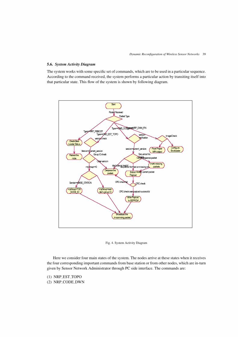
5.6. System Activity Diagram
The system works with some specific set of commands, which are to be used in a particular sequence.According to the command received, the system performs a particular action by transiting itself intothat particular state. This flow of the system is shown by following diagram.
Fig. 4. System Activity Diagram
Here we consider four main states of the system. The nodes arrive at these states when it receivesthe four corresponding important commands from base station or from other nodes, which are in-turngiven by Sensor Network Administrator through PC side interface. The commands are:
(1) NRP EST TOPO(2) NRP CODE DWN

40 Kulkarni, Sanyal, Al-Qaheri, & Sanyal
(3) NRP REBOOT(4) NRP DWN FIN
Please refer previous section for details of these commands.
6. Results
While developing the system, we used the hardware which was available to us. It consisted of 3TelosB motes and a bunch of batteries. As we were developing the system, we were testing it againstthis hardware.
The most important and critical part in the implementation was multihop data transfer. The codeimage on PC must reach the motes which reside at a distance of more than or equal to 2 hops. As wehave seen, we devised an algorithm for this. By designing specific packet formats, and the sequencein which they should be sent and received, we came up with a protocol, with which we could achieveour main goal. So while testing the dissemination part, we used the following test cases:
(1) Single Byte Test This was an elementary test case. If we can pass single byte over multihop, wecan pass many similar packets like that one. So we first tried to establish the communication bysending a single byte over the network. If this fails, no case hence forth will work.
(2) Array size=max packet payload size. Now we try to send a fully stuffed packet. The defaultmaximum payload length for tinyOS 1. X is 29 bytes. In case of improper timers, more is theprobability of packet drops when we send maximum allowed data. Since for better throughput,we will opt for this extreme case only, testing for this case is important.
(3) Number of bytes=size of buffer. We must also test if the buffering support which we provide inour implementation is enough or not. In case of insufficient buffers and inappropriate timeouts,we might get higher packet losses. Thus, this test is a type of stress test that checks whether tebuffering mechanism used in our implementation is adequate.
(4) File size=1kb Now we try to send bulk of data over the network. We test this for scalability ofour firmware in terms of data.
(5) File Size=128kb (Maximum Program size.) We now test our system for boundary value of datasize. We must be able to transfer 128 kb of data and save it on EEPROM.
With the above test cases; following was the test scenario: We were provided 3 Crossbow TelosBmotes. They have USB connectivity. We made one as base station and then tested the mote sidesoftware with different placements of nodes. We consider the following scenarios:
(1) The two motes at a distance of single hop from base station. With this we tested how efficiently,the algorithm can filter out duplicate packets so that least of them are generated, and they die assoon as generated.
(2) One mote was at a distance of one hop and the other was kept at a distance of 2 hops. With thiswe checked multi-hop dissemination ability of the system.
As far as correctness of the algorithm is concerned, it was found that in first four cases, the datawas transferred with 99% reliability. In final case, out of 20 tries, we got 2 failures, which broughtdown the reliability to 90%. The images residing on mote was transferred back to PC using a small

Dynamic Reconfiguration of Wireless Sensor Networks 41
Java interface to check correctness of data which was transferred. Out of successful transfers, thecode image was found correct in all the cases. Moreover, in all the cases the failures were detectedand the correct codes were acquired. The above results clearly demonstrated that our implementationwas working as per the goals. In particular, the failure model adopted in our work was adequate toaddress the failures in real systems. However, if more motes had been available to us then we couldhave performed more tests, particularly those related to the scalability of the system.
7. Conclusion and Future Work
In this paper, we examined existing algorithms for multihop network reprogramming of wirelesssensor networks and some flaws were observed with many. We hence developed an algorithm whichrectify some of the deficiencies that exist in some of the review algorithms like Deluge, MHOP. Wethen mathematically modeled the algorithm and derived some timer values, which were used whileimplementing the algorithms. This led to an efficient algorithm for multihop network reprogrammingof wireless sensor networks. We then made an attempt to implement this algorithm on TinyOS plat-form. Since we were implementing the system from scratch, i.e. we were even implementing singlehop network reprogramming system, instead of building it on top of existing reprogramming librarieslike XNP. Due to the large scope of the implementation part, we set a finite goal of implementingpart of the system and we succeeded. The following modules of the system were implemented:
(1) PC Side Interface in Java.(2) Base station software.(3) Reprogramming module, which successfully and reliably transfers the code image over multihop
network.
The work progress slowed down here due to unavailability of proper documentation about BootLoader of TinyOS which is required for implementation of further part. Hence, as soon as the properdocumentation of TinyOS boot loader is available, further part of the algorithm can be implemented.This part contains:
(1) Transforming the received image to boot loader understandable format.(2) Configuration of boot loader.(3) Reboot the mote, in order to run new program.
We also consider the remaining part of our problem statement as a direction for future work, inorder to make this system to a better system for remote reprogramming than the existing one viz.Deluge.
After the system is fully implemented, a comparative analysis of existing systems versus this oneis needed. This would lead to discovering possible logical flaws in the algorithm, and hence help usto improve it on various fronts. The system could also have an extensive platform support, whichcurrently is limited to Telosb motes only.
ReferencesDeng, J. Dang, R. Mishra,S. (2006). Efficiently Authenticating Code Images in Dynamically Reprogrammed
Wireless Sensor Networks, Proceedings of the 4th annual IEEE international conference on Pervasive Com-

42 Kulkarni, Sanyal, Al-Qaheri, & Sanyal
puting and Communications Workshops, 2006.Demers, A. et al.(1987). Epidemic algorithms for replicated database maintenance. In Proceedings of the Sixth
Annual ACM Symposium on Principles of Distributed Computing, pages 1-12. ACM Press, 1987.Dunkels, A. Gronvall, B. and Voigt,T. (2004) Contiki - A lightweight and flexible operating system for tiny
networked sensors. In Proceedings of the First IEEE Workshop on Embedded Networked Sensors, Tampa,Florida, USA, November 2004.
Dunkels, A. , et al. (2006). Run-Time Dynamic Linking for Reprogramming Wireless Sensor Networks, Pro-ceedings of the Fourth ACM Conference on Embedded Networked Sensor Systems (SenSys 2006), Boulder,Colorado, USA, November 2006.
Hadim, S. , Mohamed, N. (2006). Middleware Challenges and Approaches for Wireless Sensor Networks. IEEEDistributed Systems Online. 7 (3): 1. doi:10.1109/MDSO.2006.19. art. no. 0603-o3001.
Haenselmann, T. (2006). Sensornetworks. GFDL Wireless Sensor Network textbook. Retrieved on 2006-08-29.Hui, J. W., David Culler, D. (2004). The Dynamic Behavior of a Data Dissemination Protocol for Network
Programming at Scale, Proceedings of the 2nd international conference on Embedded networked sensorsystems, Baltimore, MD, USA, 2004
Jan, C. et al.(2008). Typhoon: A Reliable Data Dissemination Protocol for Wireless Sensor Networks, 5thEuropean Conference on Wireless Sensor Networks, EWSN 2008.
Jeong, J., Kim, S. and Broad, A. (2003). Network Reprogramming, TinyOS documentation, Aug. 2003Levis, P. et al. Trickle: A self-regulating algorithm for code propagation and maintenance in wireless sensor
networks. Technical report, University of California at Berkeley, 2004.Lewis, F.L. Wireless Sensor Networks, in Smart Environments: Technologies, Protocols, and Application , ed.
D.J. Cook and S.K. Das, John Wiley, New York, 2004.Mainwaring, A. et al.(2002) . Wireless Sensor Networks for Habitat Monitoring. WSNA’02, September 28,
2002, Atlanta, Georgia, USA.Ni, S.Y. ,et al. (1999). The broadcast storm problem in a mobile ad hoc network. In Proceedings of the Fifth
Annual ACM/IEEE International Conference on Mobile Computing and Networking, ACM Press, 1999.Rabiner, W., Kulik, J. and Balakrishnan, H. (1999). Adaptive Protocols for Information Dissemination in Wire-
less Sensor Networks, Proceedings of the 5th annual ACM/IEEE international conference on Mobile com-puting and networking, Seattle, Washington, United State, 1999.
Reijers, N., Langendoen, K.(2003) Efficient Code Distribution in Wireless Sensor Networks, Proceedings of the2nd ACM international conference on Wireless sensor networks and applications, San Diego, CA, USA,2003.
Romer, K., Mattern, F.(2004). The Design Space of Wireless Sensor Network. IEEE Wireless Communications,11 (6): 54-61.
Stathopoulos, T., Heidemann, J., Estrin, D. (2003). A Remote Code Update Mechanism for Wireless SensorNetworks, Technical Report CENS-TR-30, University of California, Los Angeles, Center for EmbeddedNetworked Computing, November, 2003.
University of California, Berkeley. Tinyos. http://www.tinyos.net/.


![Journal of Network and Computer Applicationsw3.ualg.pt/~arahmani/index_files/A new fuzzy negotiation...2 S. Adabi et al. / Journal of Network and Computer Applications ] (]]]]) ]]]–]]]](https://img.dokumen.tips/doc/110x75/5abe5c057f8b9ab02d8cce52/journal-of-network-and-computer-arahmaniindexfilesa-new-fuzzy-negotiation2.jpg)