Embed Size (px)
Citation preview
INTERNATIONALSTANDARD
IEC61850-7-4
First edition2003-05
Communication networks and systemsin substations –
Part 7-4:Basic communication structure for substationand feeder equipment – Compatible logical nodeclasses and data classes
Reference numberIEC 61850-7-4:2003(E)
Copyright International Electrotechnical Commission Provided by IHS under license with IEC
Not for ResaleNo reproduction or networking permitted without license from IHS
--``````-`-`,,`,,`,`,,`---
Publication numbering
As from 1 January 1997 all IEC publications are issued with a designation in the60000 series. For example, IEC 34-1 is now referred to as IEC 60034-1.
Consolidated editions
The IEC is now publishing consolidated versions of its publications. For example,edition numbers 1.0, 1.1 and 1.2 refer, respectively, to the base publication, thebase publication incorporating amendment 1 and the base publication incorporatingamendments 1 and 2.
Further information on IEC publications
The technical content of IEC publications is kept under constant review by the IEC,thus ensuring that the content reflects current technology. Information relating tothis publication, including its validity, is available in the IEC Catalogue ofpublications (see below) in addition to new editions, amendments and corrigenda.Information on the subjects under consideration and work in progress undertakenby the technical committee which has prepared this publication, as well as the listof publications issued, is also available from the following:
• IEC Web Site (www.iec.ch)
• Catalogue of IEC publications
The on-line catalogue on the IEC web site (http://www.iec.ch/searchpub/cur_fut.htm)enables you to search by a variety of criteria including text searches, technicalcommittees and date of publication. On-line information is also available onrecently issued publications, withdrawn and replaced publications, as well ascorrigenda.
• IEC Just Published This summary of recently issued publications (http://www.iec.ch/online_news/justpub/jp_entry.htm) is also available by email. Please contact the CustomerService Centre (see below) for further information.
• Customer Service Centre
If you have any questions regarding this publication or need further assistance,please contact the Customer Service Centre:
Email: [email protected]: +41 22 919 02 11Fax: +41 22 919 03 00
Copyright International Electrotechnical Commission Provided by IHS under license with IEC
Not for ResaleNo reproduction or networking permitted without license from IHS
--``````-`-`,,`,,`,`,,`---

INTERNATIONALSTANDARD
IEC61850-7-4
First edition2003-05
Communication networks and systemsin substations –
Part 7-4:Basic communication structure for substationand feeder equipment – Compatible logical nodeclasses and data classes
IEC 2003 Copyright - all rights reserved
No part of this publication may be reproduced or utilized in any form or by any means, electronic ormechanical, including photocopying and microfilm, without permission in writing from the publisher.
International Electrotechnical Commission, 3, rue de Varembé, PO Box 131, CH-1211 Geneva 20, SwitzerlandTelephone: +41 22 919 02 11 Telefax: +41 22 919 03 00 E-mail: [email protected] Web: www.iec.ch
For price, see current catalogue
PRICE CODECommission Electrotechnique InternationaleInternational Electrotechnical CommissionМеждународная Электротехническая Комиссия
XD
Copyright International Electrotechnical Commission Provided by IHS under license with IEC
Not for ResaleNo reproduction or networking permitted without license from IHS
--``````-`-`,,`,,`,`,,`---
– 2 – 61850-7-4 IEC:2003(E)
CONTENTS
FOREWORD .......................................................................................................................... 6INTRODUCTION .................................................................................................................... 81 Scope .............................................................................................................................. 92 Normative references ......................................................................................................103 Terms and definitions......................................................................................................114 Abbreviated terms ...........................................................................................................115 Logical node classes .......................................................................................................15
5.1 Logical Node groups ..............................................................................................155.2 Interpretation of Logical Node tables ......................................................................165.3 System Logical NodesLN Group: L .........................................................................17
5.3.1 General......................................................................................................175.3.2 LN: Physical device informationName: LPHD..............................................185.3.3 Common Logical Node ...............................................................................185.3.4 LN: Logical node zeroName: LLN0 .............................................................19
5.4 Logical Nodes for protection functionsLN Group: P .................................................195.4.1 Modelling remarks......................................................................................195.4.2 LN: DifferentialName: PDIF ........................................................................215.4.3 LN: Direction comparisonName: PDIR ........................................................225.4.4 LN: DistanceName: PDIS ...........................................................................225.4.5 LN: Directional overpowerName: PDOP......................................................235.4.6 LN: Directional underpowerName: PDUP ....................................................235.4.7 LN: Rate of change of frequencyName: PFRC ............................................245.4.8 LN: Harmonic restraintName: PHAR ...........................................................245.4.9 LN: Ground detectorName: PHIZ ................................................................255.4.10 LN: Instantaneous overcurrentName: PIOC ................................................255.4.11 LN: Motor restart inhibitionName: PMRI ......................................................255.4.12 LN: Motor starting time supervisionName: PMSS ........................................265.4.13 LN: Over power factorName: POPF ............................................................265.4.14 LN: Phase angle measuringName: PPAM ...................................................275.4.15 LN: Protection schemeName: PSCH...........................................................275.4.16 LN: Sensitive directional earthfaultName: PSDE .........................................285.4.17 LN: Transient earth faultName: PTEF .........................................................295.4.18 LN: Time overcurrentName: PTOC .............................................................295.4.19 LN: OverfrequencyName: PTOF .................................................................305.4.20 LN: OvervoltageName: PTOV .....................................................................305.4.21 LN: Protection trip conditioningName: PTRC...............................................305.4.22 LN: Thermal overloadName: PTTR .............................................................315.4.23 LN: UndercurrentName: PTUC ...................................................................325.4.24 LN: UndervoltageName: PTUV ...................................................................325.4.25 LN: Underpower factorName: PUPF ...........................................................335.4.26 LN: UnderfrequencyName: PTUF ...............................................................335.4.27 LN: Voltage controlled time overcurrentName: PVOC .................................345.4.28 LN: Volts per HzName: PVPH.....................................................................345.4.29 LN: Zero speed or underspeedName: PZSU ...............................................35
Copyright International Electrotechnical Commission Provided by IHS under license with IEC
Not for ResaleNo reproduction or networking permitted without license from IHS
--``````-`-`,,`,,`,`,,`---

61850-7-4 IEC:2003(E) – 3 –
5.5 Logical Nodes for protection related functionsLN Group: R .....................................355.5.1 Modelling Remarks ....................................................................................355.5.2 LN: Disturbance recorder functionName: RDRE..........................................365.5.3 LN: Disturbance recorder channel analogueName: RADR ...........................375.5.4 LN: Disturbance recorder channel binaryName: RBDR................................375.5.5 LN: Disturbance record handlingName: RDRS ............................................385.5.6 LN: Breaker failureName: RBRF.................................................................385.5.7 LN: Directional elementName: RDIR...........................................................385.5.8 LN: Fault locatorName: RFLO ....................................................................395.5.9 LN: Power swing detection/blockingName: RPSB .......................................395.5.10 LN: AutoreclosingName: RREC ..................................................................405.5.11 LN: Synchronism-check or synchronisingName: RSYN ...............................41
5.6 Logical Nodes for controlLN Group: C ....................................................................425.6.1 Modelling remarks......................................................................................425.6.2 LN: Alarm handlingName: CALH.................................................................425.6.3 LN: Cooling group controlName: CCGR ......................................................425.6.4 LN: InterlockingName: CILO .......................................................................435.6.5 LN: Point-on-wave switchingName: CPOW .................................................435.6.6 LN: Switch controllerName: CSWI ..............................................................44
5.7 Logical nodes for generic referencesLN Group: G ..................................................445.7.1 LN: Generic automatic process controlName: GAPC...................................445.7.2 LN: Generic process I/OName: GGIO .........................................................455.7.3 LN: Generic security applicationName: GSAL .............................................45
5.8 Logical Nodes for interfacing and archivingLN Group: I...........................................465.8.1 LN: ArchivingName: IARC ..........................................................................465.8.2 LN: Human machine interfaceName: IHMI ..................................................465.8.3 LN: Telecontrol interfaceName: ITCI...........................................................475.8.4 LN: Telemonitoring interfaceName: ITMI.....................................................47
5.9 Logical Nodes for automatic controlLN Group: A.....................................................475.9.1 Modelling remarks......................................................................................475.9.2 LN: Neutral current regulatorName: ANCR..................................................475.9.3 LN: Reactive power controlName: ARCO ....................................................485.9.4 LN: Automatic tap changer controllerName: ATCC......................................485.9.5 LN: Voltage controlName: AVCO ................................................................49
5.10 Logical Nodes for metering and measurementLN Group: M ....................................505.10.1 Modelling remarks......................................................................................505.10.2 LN: Differential measurementsName: MDIF ................................................505.10.3 LN: Harmonics or interharmonicsName: MHAI ............................................515.10.4 LN: Non phase related harmonics or interharmonicsName: MHAN ..............525.10.5 LN: MeteringName: MMTR .........................................................................545.10.6 LN: Non phase related MeasurementName: MMXN ....................................545.10.7 LN: MeasurementName: MMXU .................................................................555.10.8 LN: Sequence and imbalanceName: MSQI .................................................555.10.9 LN: Metering StatisticsName: MSTA ...........................................................56
5.11 Logical Nodes for sensors and monitoringLN Group: S ...........................................575.11.1 Modelling remarks......................................................................................575.11.2 LN: Monitoring and diagnostics for arcsName: SARC..................................575.11.3 LN: Insulation medium supervision (gas)Name: SIMG.................................57
Copyright International Electrotechnical Commission Provided by IHS under license with IEC
Not for ResaleNo reproduction or networking permitted without license from IHS
--``````-`-`,,`,,`,`,,`---
– 4 – 61850-7-4 IEC:2003(E)
5.11.4 LN: Insulation medium supervision (liquid)Name: SIML ...............................585.11.5 LN: Monitoring and diagnostics for partial dischargesName: SPDC .............59
5.12 Logical Nodes for switchgearLN Group: X ..............................................................595.12.1 LN: Circuit breakerName: XCBR.................................................................595.12.2 LN: Circuit switchName: XSWI ...................................................................60
5.13 Logical Nodes for instrument transformersLN Group: T ..........................................605.13.1 LN: Current transformerName: TCTR .........................................................605.13.2 LN: Voltage transformerName: TVTR .........................................................61
5.14 Logical Nodes for power transformersLN Group: Y .................................................615.14.1 LN: Earth fault neutralizer (Petersen coil)Name: YEFN ...............................615.14.2 LN: Tap changerName: YLTC.....................................................................625.14.3 LN: Power shuntName: YPSH ....................................................................625.14.4 LN: Power transformerName: YPTR ...........................................................63
5.15 Logical Nodes for further power system equipmentLN Group: Z ..............................635.15.1 LN: Auxiliary networkName: ZAXN..............................................................635.15.2 LN: BatteryName: ZBAT .............................................................................645.15.3 LN: BushingName: ZBSH ...........................................................................645.15.4 LN: Power cableName: ZCAB.....................................................................655.15.5 LN: Capacitor bankName: ZCAP ................................................................655.15.6 LN: ConverterName: ZCON ........................................................................655.15.7 LN: GeneratorName: ZGEN........................................................................655.15.8 LN: Gas insulated lineName: ZGIL..............................................................665.15.9 LN: Power overhead lineName: ZLIN ..........................................................665.15.10 LN: MotorName: ZMOT ..............................................................................675.15.11 LN: ReactorName: ZREA............................................................................675.15.12 LN: Rotating reactive componentName: ZRRC ...........................................675.15.13 LN: Surge arrestorName: ZSAR .................................................................685.15.14 LN: Thyristor controlled frequency converterName: ZTCF ...........................685.15.15 LN: Thyristor controlled reactive componentName: ZTCR ...........................68
6 Data name semantics......................................................................................................69
Annex A (normative) Extension rules ....................................................................................91A.1 The use of Logical Nodes and Data and its extensions ....................................................91
A.1.1 Basic rules .............................................................................................................91A.2 Multiple instances of LN classes for dedicated and complex functions .............................91
A.2.1 Example for time overcurrent .................................................................................91A.2.2 Example for Distance .............................................................................................91A.2.3 Example for Power transformer ..............................................................................92A.2.4 Example for Auxiliary network ................................................................................92
A.3 Specialisation of Data by use of the number extension ....................................................92A.4 Rules for names of new Logical Nodes ............................................................................92A.5 Examples for new LNs ....................................................................................................93
A.5.1 New LN “Automatic door entrance control” .............................................................93A.5.2 New LN “Fire protection” ........................................................................................93
A.6 Rules for names of new Data ..........................................................................................93A.7 Example for new Data .....................................................................................................93A.8 Rules for new Common Data Classes (CDC) ...................................................................94
Copyright International Electrotechnical Commission Provided by IHS under license with IEC
Not for ResaleNo reproduction or networking permitted without license from IHS
--``````-`-`,,`,,`,`,,`---
61850-7-4 IEC:2003(E) – 5 –
Annex B (informative) Modelling examples............................................................................95B.1 PTEF and PSDE .............................................................................................................95B.2 PSCH and PTRC.............................................................................................................96B.3 MDIF and PDIF ...............................................................................................................97B.4 RDRE and Disturbance Recorder ....................................................................................98B.5 PTRC..............................................................................................................................99B.6 PDIR 100B.7 RREC ...........................................................................................................................101B.8 PDIS 102
Annex C (informative) Relationship between this standard and IEC 61850-5 .......................104
Figure 1 – Overview of this standard......................................................................................10Figure 2 – LN Relationships...................................................................................................17Figure B.1 – Fault current IF in a compensated network with earth fault..................................95Figure B.2 – Use of PSCH and PTRC ....................................................................................96Figure B.3 – Use of MDIF and PDIF.......................................................................................97Figure B.4 – Modelling of Disturbance Recorder ....................................................................98Figure B.5 – Examples for allocation of Logical Nodes to IEDs ...............................................99Figure B.6 – Use of PDIR ....................................................................................................100Figure B.7 – Use of RREC ...................................................................................................101
Table 1 – List of Logical Node Groups ...................................................................................15Table 2 – Interpretation of Logical Node tables ......................................................................16Table 3 – Relation between IEC 61850-5 and IEC 61850-7-4 (this standard) forprotection LNs .......................................................................................................................20Table 4 – Relation between IEC 61850-5 and IEC 61850-7-4 for protection related LNs .........35Table 5 – Relation between IEC 61850-5 and IEC 61850-7-4 for control LNs ..........................42Table 6 – Relation between IEC 61850-5 and IEC 61850-7-4 for automatic control LNs ..........47Table 7 – Relation between IEC 61850-5 and IEC 61850-7-4 for metering andmeasurement LNs .................................................................................................................50Table 8 – Relation between IEC 61850-5 and IEC 61850-7-4 for sensorsand monitoring LNs ...............................................................................................................57Table 9 – Description of Data ................................................................................................69Table C.1 – Relationship between IEC 61850-5 and this standard for somemiscellaneous LNs ..............................................................................................................104
Copyright International Electrotechnical Commission Provided by IHS under license with IEC
Not for ResaleNo reproduction or networking permitted without license from IHS
--``````-`-`,,`,,`,`,,`---
– 6 – 61850-7-4 IEC:2003(E)
INTERNATIONAL ELECTROTECHNICAL COMMISSION___________
COMMUNICATION NETWORKS AND SYSTEMS IN SUBSTATIONS –
Part 7-4: Basic communication structure for substationand feeder equipment – Compatible logical node classes
and data classes
FOREWORD1) The IEC (International Electrotechnical Commission) is a worldwide organization for standardization comprising
all national electrotechnical committees (IEC National Committees). The object of the IEC is to promoteinternational co-operation on all questions concerning standardization in the electrical and electronic fields. Tothis end and in addition to other activities, the IEC publishes International Standards. Their preparation isentrusted to technical committees; any IEC National Committee interested in the subject dealt with mayparticipate in this preparatory work. International, governmental and non-governmental organizations liaisingwith the IEC also participate in this preparation. The IEC collaborates closely with the International Organizationfor Standardization (ISO) in accordance with conditions determined by agreement between the twoorganizations.
2) The formal decisions or agreements of the IEC on technical matters express, as nearly as possible, aninternational consensus of opinion on the relevant subjects since each technical committee has representationfrom all interested National Committees.
3) The documents produced have the form of recommendations for international use and are published in the formof standards, technical specifications, technical reports or guides and they are accepted by the NationalCommittees in that sense.
4) In order to promote international unification, IEC National Committees undertake to apply IEC InternationalStandards transparently to the maximum extent possible in their national and regional standards. Anydivergence between the IEC Standard and the corresponding national or regional standard shall be clearlyindicated in the latter.
5) The IEC provides no marking procedure to indicate its approval and cannot be rendered responsible for anyequipment declared to be in conformity with one of its standards.
6) Attention is drawn to the possibility that some of the elements of this International Standard may be the subjectof patent rights. The IEC shall not be held responsible for identifying any or all such patent rights.
International Standard IEC 61850-7-4 has been prepared by IEC technical committee 57:Power system control and associated communications.
The text of this standard is based on the following documents:
FDIS Report on voting
57/622/FDIS 57/640/RVD
Full information on the voting for the approval of this standard can be found in the report onvoting indicated in the above table.
This publication has been drafted in accordance with the ISO/IEC Directives, Part 2.
Copyright International Electrotechnical Commission Provided by IHS under license with IEC
Not for ResaleNo reproduction or networking permitted without license from IHS
--``````-`-`,,`,,`,`,,`---
61850-7-4 IEC:2003(E) – 7 –
IEC 61850 consists of the following parts, under the general title Communication networksand systems in substations:Part 1: Introduction and overview
Part 2: Glossary 1
Part 3: General requirements
Part 4: System and project management
Part 5: Communication requirements for functions and device models 2
Part 6: Configuration description language for communication in electrical substationsrelated to IEDs 1
Part 7-1: Basic communication structure for substation and feeder equipment – Principles andmodels
Part 7-2: Basic communication structure for substation and feeder equipment – Abstractcommunication service interface (ACSI)
Part 7-3: Basic communication structure for substation and feeder equipment – Common dataclasses
Part 7-4: Basic communication structure for substation and feeder equipment – Compatiblelogical node classes and data classes
Part 8-1: Specific communication service mapping (SCSM) – Mappings to MMS (ISO/IEC9506-1 and ISO/IEC 9506-2) and to ISO/IEC 8802-3 1
Part 9-1: Specific communication service mapping (SCSM) – Sampled values over serialunidirectional multidrop point to point link
Part 9-2: Specific communication service mapping (SCSM) – Sampled values over ISO/IEC8802-3 1
Part 10: Conformance testing 1
The content of this part of IEC 61850 is based on existing or emerging standards andapplications. In particular the definitions are based upon:
• the specific data types defined in IEC 60870-5-101 and IEC 60870-5-103;
• the common class definitions from the Utility Communication Architecture 2.0: GenericObject Models for Substation and Feeder Equipment (GOMSFE) (IEEE TR 1550);
• CIGRE Report 34-03, Communication requirements in terms of data flow within substations,December 1996.
The committee has decided that the contents of this publication will remain unchanged until 2005.At this date, the publication will be
• reconfirmed;• withdrawn;• replaced by a revised edition, or• amended.
___________1 Under consideration.
2 To be published.
Copyright International Electrotechnical Commission Provided by IHS under license with IEC
Not for ResaleNo reproduction or networking permitted without license from IHS
--``````-`-`,,`,,`,`,,`---

– 8 – 61850-7-4 IEC:2003(E)
INTRODUCTION
This part of IEC 61850 is a part of set of specifications (IEC 61850). IEC 61850 defines asubstation communication architecture. This architecture has been chosen to provide abstractdefinitions of classes and services such that the specifications are independent of specificprotocol stacks, implementations, and operating systems. The mapping of these abstractclasses and services to communication stacks is outside the scope of IEC 61850-7-x and maybe found in IEC 61850-8-x and in IEC 61850-9-x.
IEC 61850-7-1 gives an overview of this communication architecture. IEC 61850-7-3 definescommon attribute types and common data classes related to substation applications.The attributes of the common data classes may be accessed using services definedin IEC 61850-7-2. These common data classes are used in this part to define the compatibledata classes.
To reach interoperability, all data in the data model need a strong definition with regard tosyntax and semantics. The semantics of the data is mainly provided by names assigned tological nodes and data they contain, as defined in this part. Interoperability is easiest if asmuch as possible of the data are defined as mandatory. Because of different philosophies andtechnical features, settings were declared as optional in this edition of the standard. After someexperience has been gained with this standard, this decision may be reviewed in anamendment or in the next revision of this part.
It should be noted that data with full semantics is only one of the elements required to achieveinteroperability. Since data and services are hosted by devices (IED), a proper device model isneeded along with compatible, domain specific services (see IEC 61850-7-2).
The compatible logical node name and data name definitions found in this part and theassociated semantics are fixed. The syntax of the type definitions of all data classes areabstract definitions provided in IEC 61850-7-2 and IEC 61850-7-3. Not all features of logicalnodes are listed in this part for example data sets and logs are covered in IEC 61850-7-2.
Copyright International Electrotechnical Commission Provided by IHS under license with IEC
Not for ResaleNo reproduction or networking permitted without license from IHS
--``````-`-`,,`,,`,`,,`---

61850-7-4 IEC:2003(E) – 9 –
COMMUNICATION NETWORKS AND SYSTEMS IN SUBSTATIONS –
Part 7-4: Basic communication structure for substationand feeder equipment – Compatible logical node classes
and data classes
1 Scope
This part of IEC 61850 specifies the information model of devices and functions related tosubstation applications. In particular, it specifies the compatible logical node names and datanames for communication between Intelligent Electronic Devices (IED). This includes therelationship between Logical Nodes and Data.
The Logical Node Names and Data Names defined in this document are part of the classmodel introduced in IEC 61850-7-1 and defined in IEC 61850-7-2. The names defined in thisdocument are used to build the hierarchical object references applied for communicating withIEDs in substations and on distribution feeders. The naming conventions of IEC 61850-7-2 areapplied in this part.
To avoid private, incompatible extension rules this part specifies normative naming rules formultiple instances and private extensions of Logical Node (LN) Classes and Data Names.
In Annex A, all rules are given (making use of examples) for:
• multiple instances of logical node classes by use of a LN instance identification (ID);
• multiple instances of data by use of a data instance ID;
• selecting data not included in LN out of the complete data name set;
• creating new logical node classes and data names.
In Annex B, examples are given for:
• the use of Logical Nodes in complex situations like line protection schemes;
• multiple instances of Logical Nodes with different levels of functionality.
This part does not provide tutorial material. It is recommended those parts IEC 61850-5and IEC 61850-7-1 be read first, in conjunction with IEC 61850-7-3, and IEC 61850-7-2. Thispart does not discuss implementation issues. The relationship between this standard andIEC 61850-5 is outlined in Annex C.
This standard is applicable to describe device models and functions of substation and feederequipment. The concepts defined in this standard may also be applied to describe devicemodels and functions for:
• substation to substation information exchange,
• substation to control centre information exchange,
• power plant to control centre information exchange,
• information exchange for distributed generation,
• information exchange for distributed automation, or
• information exchange for metering.
Figure 1 provides a general overview of this document.
Copyright International Electrotechnical Commission Provided by IHS under license with IEC
Not for ResaleNo reproduction or networking permitted without license from IHS
--``````-`-`,,`,,`,`,,`---
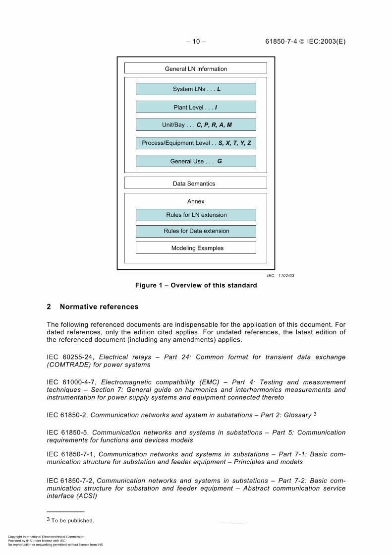
– 10 – 61850-7-4 IEC:2003(E)
Plant Level . . . I
Unit/Bay . . . C, P, R, A, M
Process/Equipment Level . . S, X, T, Y, Z
General Use . . . G
Rules for LN extension
General LN Information
Data Semantics
Annex
System LNs . . . L
Rules for Data extension
Modeling Examples
Figure 1 – Overview of this standard
2 Normative references
The following referenced documents are indispensable for the application of this document. Fordated references, only the edition cited applies. For undated references, the latest edition ofthe referenced document (including any amendments) applies.
IEC 60255-24, Electrical relays – Part 24: Common format for transient data exchange(COMTRADE) for power systems
IEC 61000-4-7, Electromagnetic compatibility (EMC) – Part 4: Testing and measurementtechniques – Section 7: General guide on harmonics and interharmonics measurements andinstrumentation for power supply systems and equipment connected thereto
IEC 61850-2, Communication networks and system in substations – Part 2: Glossary 3
IEC 61850-5, Communication networks and systems in substations – Part 5: Communicationrequirements for functions and devices models
IEC 61850-7-1, Communication networks and systems in substations – Part 7-1: Basic com-munication structure for substation and feeder equipment – Principles and models
IEC 61850-7-2, Communication networks and systems in substations – Part 7-2: Basic com-munication structure for substation and feeder equipment – Abstract communication serviceinterface (ACSI)
___________3 To be published.
IEC 1102/03
Copyright International Electrotechnical Commission Provided by IHS under license with IEC
Not for ResaleNo reproduction or networking permitted without license from IHS
--``````-`-`,,`,,`,`,,`---
61850-7-4 IEC:2003(E) – 11 –
IEC 61850-7-3, Communication networks and systems in substations – Part 7-3: Basiccommunication structure for substation and feeder equipment – Common data classes
IEEE 519:1992, IEEE Recommended Practises and Requirements for Harmonic Control inElectrical Power Systems
IEEE 1459:2000, IEEE Trial Use Standard Definitions for the Measurement of Electric PowerQuantities Under Sinusoidal, Nonsinusoidal, Balanced or Unbalanced Conditions
IEEE C37.2:1996, Electrical Power System Device Function Numbers and Contact Designation
3 Terms and definitions
For the purpose of this international standard the terms and definitions given in IEC 61850-24and IEC 61850-7-2 apply.
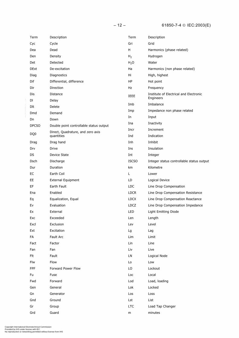
4 Abbreviated terms
The following terms are used to build concatenated Data Names. For example, ChNum isconstructed by using two terms "Ch" which stands for "Channel" and "Num" which stands for"Number". Thus the concatenated name represents a "channel number".
___________4 Under consideration.
Term Description
A Current
Acs Access
ACSI Abstract Communication Service Interface
Acu Acoustic
Age Ageing
Alm Alarm
Amp Current non phase related
An Analogue
Ang Angle
Auth Authorisation
Auto Automatic
Aux Auxiliary
Av Average
B Bushing
Bat Battery
Beh Behaviour
Bin Binary
Blk Block, blocked
Bnd Band
Bo Bottom
Cap Capability
Capac Capacitance
Car Carrier
Term Description
CB Circuit Breaker
CDC Common Data Class
CE Cooling Equipment
Cf Crest factor
Cfg Configuration
CG Core Ground
Ch Channel
Cha Charger
Chg Change
Chk Check
Chr Characteristic
Cir Circulating
Clc Calculate
Clk Clock, clockwise
Cls Close
Cnt Counter
Col Coil
Cor Correction
Crd Coordination
Crv Curve
CT Current Transducer
Ctl Control
Ctr Center
Copyright International Electrotechnical Commission Provided by IHS under license with IEC
Not for ResaleNo reproduction or networking permitted without license from IHS
--``````-`-`,,`,,`,`,,`---
– 12 – 61850-7-4 IEC:2003(E)
Term Description
Cyc Cycle
Dea Dead
Den Density
Det Detected
DExt De-excitation
Diag Diagnostics
Dif Differential, difference
Dir Direction
Dis Distance
Dl Delay
Dlt Delete
Dmd Demand
Dn Down
DPCSO Double point controllable status output
DQ0 Direct, Quadrature, and zero axisquantities
Drag Drag hand
Drv Drive
DS Device State
Dsch Discharge
Dur Duration
EC Earth Coil
EE External Equipment
EF Earth Fault
Ena Enabled
Eq Equalization, Equal
Ev Evaluation
Ex External
Exc Exceeded
Excl Exclusion
Ext Excitation
FA Fault Arc
Fact Factor
Fan Fan
Flt Fault
Flw Flow
FPF Forward Power Flow
Fu Fuse
Fwd Forward
Gen General
Gn Generator
Gnd Ground
Gr Group
Grd Guard
Term Description
Gri Grid
H Harmonics (phase related)
H2 Hydrogen
H2O Water
Ha Harmonics (non phase related)
Hi High, highest
HP Hot point
Hz Frequency
IEEE Institute of Electrical and ElectronicEngineers
Imb Imbalance
Imp Impedance non phase related
In Input
Ina Inactivity
Incr Increment
Ind Indication
Inh Inhibit
Ins Insulation
Int Integer
ISCSO Integer status controllable status output
km Kilometre
L Lower
LD Logical Device
LDC Line Drop Compensation
LDCR Line Drop Compensation Resistance
LDCX Line Drop Compensation Reactance
LDCZ Line Drop Compensation Impedance
LED Light Emitting Diode
Len Length
Lev Level
Lg Lag
Lim Limit
Lin Line
Liv Live
LN Logical Node
Lo Low
LO Lockout
Loc Local
Lod Load, loading
Lok Locked
Los Loss
Lst List
LTC Load Tap Changer
m minutes
Copyright International Electrotechnical Commission Provided by IHS under license with IEC
Not for ResaleNo reproduction or networking permitted without license from IHS
--``````-`-`,,`,,`,`,,`---

61850-7-4 IEC:2003(E) – 13 –
Term Description
M/O Data Object is Mandatory or Optional
Max Maximum
Mem Memory
Min Minimum
Mod Mode
Mot Motor
Ms Milliseconds
Mst Moisture
MT Main Tank
N Neutral
Nam Name
Net Net sum
Ng Negative
Nom Nominal, Normalising
Num Number
Ofs Offset
Op Operate, Operating
Opn Open
Out Output
Ov Over, Override, Overflow
Pa Partial
Par Parallel
Pct Percent
Per Periodic
PF Power Factor
Ph Phase
Phy Physical
Pls Pulse
Plt Plate
Pmp Pump
Po Polar
Pol Polarizing
Pos Position
POW Point on wave switching
PP Phase to phase
PPV Phase to phase voltage
Pres Pressure
Prg Progress, in progress
Pri Primary
Pro Protection
Ps Positive
Pst Post
Pwr Power
Qty Quantity
Term Description
R Raise
R0 Zero sequence resistance
R1 Positive sequence resistance
Rat Winding ratio
Rcd Record, recording
Rch Reach
Rcl Reclaim
Re Retry
React Reactance; Reactive
Rec Reclose
Red Reduction
Rel Release
Rem Remote
Res Residual
Ris Resistance
Rl Relation, relative
Rms Root mean square
Rot Rotation, Rotor
Rs Reset, Resetable
Rsl Result
Rst Restraint
Rsv Reserve
Rte Rate
Rtg Rating
Rv Reverse
Rx Receive, received
S1 Step one
S2 Step two
Sch Scheme
SCO Supply change over
SCSM Specific Communication Service Mapping
Sec Security
Seq Sequence
Set Setting
Sh Shunt
Spd Speed
SPl Single Pole
SPCSO Single point controllable status output
Src Source
St Status
Stat Statistics
Stop Stop
Std Standard
Str Start
Copyright International Electrotechnical Commission Provided by IHS under license with IEC
Not for ResaleNo reproduction or networking permitted without license from IHS
--``````-`-`,,`,,`,`,,`---

– 14 – 61850-7-4 IEC:2003(E)
Term Description
Sup Supply
Svc Service
Sw Switch
Swg Swing
Syn Synchronisation
Tap Tap
Td Total distortion
Tdf Transformer derating factor
Test Test
Thd Total Harmonic Distortion
Thm Thermal
TiF Telephone influence factor
Tm
TimeTmh = Time in hTmm = Time in minTms = Time in sTmms = Time in ms
Tmp Temperature (°C)
To Top
Tot Total
TP Three pole
Tr Trip
Trg Trigger
Ts Total signed
Tu Total unsigned
Tx Transmit, transmitted
Typ Type
Term Description
Un Under
V Voltage
VA Volt Amperes
Vac Vacuum
Val Value
VAr Volt Amperes Reactive
Vlv Valve
Vol Voltage non phase related
VT Voltage Transducer
W Active Power
Wac Watchdog
Watt Active Power non phase related
Wei Weak End Infeed
Wh Watt hours
Wid Width
Win Window
Wrm Warm
X0 Zero sequence reactance
X1 Positive sequence reactance
Z Impedance
Z0 Zero sequence impedance
Z1 Positive sequence impedance
Zer Zero
Zn Zone
Zro Zero sequence method
Copyright International Electrotechnical Commission Provided by IHS under license with IEC
Not for ResaleNo reproduction or networking permitted without license from IHS
--``````-`-`,,`,,`,`,,`---

61850-7-4 IEC:2003(E) – 15 –
5 Logical node classes
5.1 Logical Node groups
Logical nodes are grouped according to the Logical Node Groups listed in Table 1. The namesof Logical Nodes shall begin with the character representing the group to which the LogicalNode belongs. For modelling per phase (for example switches or instrument transformers), oneinstance per phase shall be created (see A.2.3 for example).
Table 1 – List of Logical Node Groups
Group Indicator Logical node groups
A Automatic Control
C Supervisory control
G Generic Function References
I Interfacing and Archiving
L System Logical Nodes
M Metering and Measurement
P Protection Functions
R Protection Related Functions
S a) Sensors, Monitoring
T a) Instrument Transformer
X a) Switchgear
Y a) Power Transformer and Related Functions
Z a) Further (power system) Equipment
a) LNs of this group exist in dedicated IEDs if a process bus is used. Without a process bus, LNs of this group are theI/Os in the hardwired IED one level higher (for example in a bay unit) representing the external device by its inputsand outputs (process image – see Figure B.5 for example).
NOTE The following letters are recommended for use by other technical committees: H-Hydropower, F-Fuel cells,W-Wind, O-Solar, B-Battery, N-Power plant.
Copyright International Electrotechnical Commission Provided by IHS under license with IEC
Not for ResaleNo reproduction or networking permitted without license from IHS
--``````-`-`,,`,,`,`,,`---

– 16 – 61850-7-4 IEC:2003(E)
5.2 Interpretation of Logical Node tables
The interpretation of the headings for the logical node tables is presented in Table 2.
Table 2 – Interpretation of Logical Node tables
Column heading Description
Attribute Name Name of the Data
Attr. Type Common Data Class that defines the structure of the data. See IEC 61850-7-3.
Explanation Short explanation of the data and how it is used.
T
Transient Data – the status of data with this designation is momentary and must belogged or reported to provide evidence of their momentary state. Some T may be onlyvalid on a modelling level. The TRANSIENT property of DATA only applies to BOOLEANprocess data attributes (FC=ST) of that DATA. Transient DATA is identical to normalDATA, except that for the process state change from TRUE to FALSE no event may begenerated for reporting and for logging.
M/O
This column defines whether data, data sets, control blocks or services are mandatory(M) or optional (O) for the instantiation of a specific Logical Node.
NOTE The attributes for data that are instantiated may also be mandatory or optionalbased on the CDC (Attribute Type) definition in IEC 61850-7-3.
Where the letter C is used for “conditional”, at least one of the items of data labelledwith C shall be used from each category where C occurs.
All Attribute Names (Data Names) are listed alphabetically in Clause 6. The data in the LogicalNodes Classes are grouped into various categories (as described below) for the convenienceof the reader. This grouping may result in some overlapping.
All Attribute Names (Data Names) are listed alphabetically in Clause 6. Despite someoverlapping, the data in the Logical Nodes Classes are grouped for the convenience of thereader into some of the following categories.
Common Logical Node Informationis information independent of the dedicated function represented by the LN class. Mandatorydata (M) are common to all LN classes; optional data (O) are valid for a reasonable subset ofLN classes.
Status Informationis data, which shows either the status of the process or of the function allocated to the LNclass. This information is produced locally and cannot be changed remotely unless substitutionis applicable. Data such as “start” or “trip” are listed in this category. Most of these data aremandatory.
Settingsare data which are needed for the function to operate. Since many settings are dependent onthe implementation of the function, only a commonly agreed minimum is standardised. Theymay be changed remotely, but normally not very often.
Measured valuesare analogue data measured from the process or calculated in the functions such as currents,voltages, power, etc. This information is produced locally and cannot be changed remotelyunless substitution is applicable.
Controlsare data which are changed by commands such as switchgear state (ON/OFF), tap changerposition or resetable counters. They are typically changed remotely, and are changed duringoperation much more than Settings.
Copyright International Electrotechnical Commission Provided by IHS under license with IEC
Not for ResaleNo reproduction or networking permitted without license from IHS
--``````-`-`,,`,,`,`,,`---

61850-7-4 IEC:2003(E) – 17 –
Metered valuesare analogue data representing quantities measured over time, e.g. energy. This information isproduced locally and cannot be changed remotely unless substitution is applicable.
5.3 System Logical Nodes LN Group: L
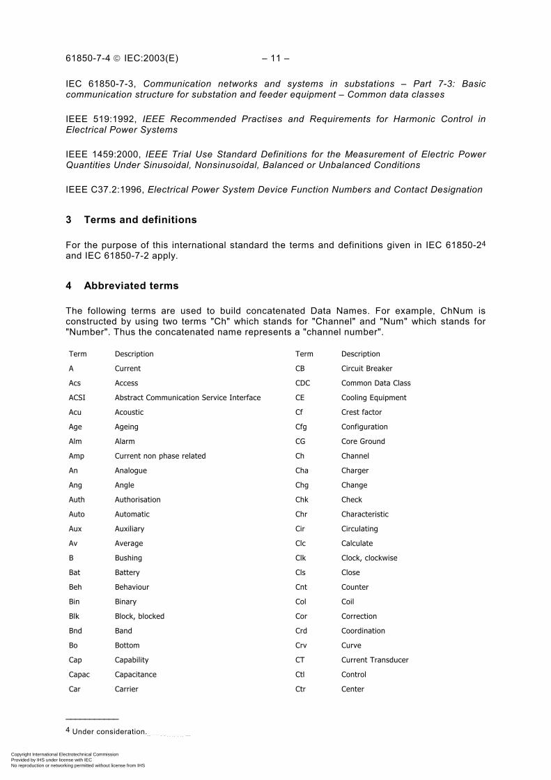
5.3.1 General
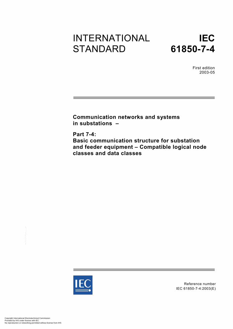
In this subclause, the system specific information is defined. This includes Common LogicalNode Information (for example logical node mode control, nameplate information, operationcounters) as well as information related to the physical device (LPHD) implementing the logicaldevices and logical nodes. These logical nodes (LPHD and Common LN) are independent ofthe application domain. All other logical nodes are domain specific, but inherit mandatory andoptional Data from these system logical nodes.
LN Abstract LN Classdefined in IEC 61850-7-2
Domain Specific LN for example
XCBR
Common LNLPHD
LLN0
Figure 2 – LN Relationships
All logical node classes defined in this document inherit their structure from the abstract logicalnode class (LN, see Figure 2) defined in IEC 61850-7-2. Apart from the logical node class‘Physical Device Information’ (LPHD) all logical node classes (LLN0 and domain specific LNs)defined in this document inherit at least the mandatory data of the common logical node(Common LN).
IEC 1103/03
Copyright International Electrotechnical Commission Provided by IHS under license with IEC
Not for ResaleNo reproduction or networking permitted without license from IHS
--``````-`-`,,`,,`,`,,`---

– 18 – 61850-7-4 IEC:2003(E)
5.3.2 LN: Physical device information Name: LPHD
This LN is introduced in this part to model common issues for physical devices.
LPHD class
Attribute Name Attr. Type Explanation T M/O
LNName Shall be inherited from Logical-Node Class (see IEC 61850-7-2)
Data
PhyNam DPL Physical device name plate M
PhyHealth INS Physical device health M
OutOv SPS Output communications buffer overflow O
Proxy SPS Indicates if this LN is a proxy M
InOv SPS Input communications buffer overflow O
NumPwrUp INS Number of Power ups O
WrmStr INS Number of Warm Starts O
WacTrg INS Number of watchdog device resets detected O
PwrUp SPS Power Up detected O
PwrDn SPS Power Down detected O
PwrSupAlm SPS External power supply alarm O
RsStat SPC Reset device statistics T O
5.3.3 Common Logical Node
The compatible logical nodes classes defined in this document are specialisations of thiscommon logical node class.
Common Logical Node classAttribute Name Attr. Type Explanation T M/O
LNName Shall be inherited from Logical-Node Class (see IEC 61850-7-2)
DataMandatory Logical Node Information (Shall be inherited by ALL LN but LPHD)
Mod INC Mode M
Beh INS Behaviour M
Health INS Health M
NamPlt LPL Name plate M
Optional Logical Node Information
Loc SPS Local operation O
EEHealth INS External equipment health O
EEName DPL External equipment name plate O
OpCntRs INC Operation counter resetable O
OpCnt INS Operation counter O
OpTmh INS Operation time O
Data Sets (see IEC 61850-7-2)Inherited and specialised from Logical Node class (see IEC 61850-7-2)Control Blocks (see IEC 61850-7-2)Inherited and specialised from Logical Node class (see IEC 61850-7-2)Services (see IEC 61850-7-2)Inherited and specialised from Logical Node class (see IEC 61850-7-2)
Copyright International Electrotechnical Commission Provided by IHS under license with IEC
Not for ResaleNo reproduction or networking permitted without license from IHS
--``````-`-`,,`,,`,`,,`---

61850-7-4 IEC:2003(E) – 19 –
A specialisation of this Common Logical Node class shall inherit all Data, Data Sets, ControlBlocks and Services that are mandatory. For the optional data, there are three possibilities forspecialisation:• not to inherit these items;• inherit these items and leave them as optional;• inherit these items and define them as mandatory.
5.3.4 LN: Logical node zero Name: LLN0
This LN shall be used to address common issues for Logical Devices.
LLNO classAttribute Name Attr. Type Explanation T M/O
LNName Shall be inherited from Logical-Node Class (see IEC 61850-7-2)
DataCommon Logical Node Information
LN shall inherit all Mandatory Data from Common Logical Node Class M
Loc SPS Local operation for complete logical device O
OpTmh INS Operation time O
Controls
Diag SPC Run Diagnostics O
LEDRs SPC LED reset T O
5.4 Logical Nodes for protection functions LN Group: P
5.4.1 Modelling remarks
This section refers to modelling of protection and protection related Logical Nodes and showsthe relation (see Table 3) between IEC 61850-5 and the Logical Node class definitionsaccording to this document.
• If there are several stages to one function (i.e. for multi-zone relay), each stage shall be aseparate instance of the LN. Examples are PDIS (n zones) or PTOV (2 stages).
• Multiple instances shall be used if LNs of the same LN class are operating with differentsetting groups in parallel.
• If different measuring principles such as phase or ground are required, each shall berepresented by an instance of the same basic function. An example is PTOC (used forphase or ground in dedicated instances).
• The logical nodes are defined in IEC 61850-5 from protection requirements, however formodelling purposes, some logical nodes have been split (see table below).
• Logical Nodes from IEC 61850-5 are modelled using combinations of the LNs defined inthis part (see table below).
• Other logical nodes have been added to model complex protection devices and schemes(see the following clauses). As an example, line protection uses LN PSCH to combine theoutputs from multiple protection LNs.
• The protection functions provide (if applicable) the data Str (Start) with directioninformation. In the case of a protection function which provides no direction information, thedirection “unknown” shall be transmitted. The data Str is summarised by LN PTRC.
• If the fault direction is provided in Str (Start), the directional protection may be modelledwithout the Directional Element LN RDIR. If any of the settings provided by LN RDIR areneeded, the LN RDIR shall be used.
• The protection functions provide (if applicable) the data Op (Operate) without directioninformation. The data Op is conditioned by LN PTRC resulting in the data Tr (Real Trip), i.e.between every protection LN and the circuit breaker node XCBR shall be a LN PTRC.
Copyright International Electrotechnical Commission Provided by IHS under license with IEC
Not for ResaleNo reproduction or networking permitted without license from IHS
--``````-`-`,,`,,`,`,,`---

– 20 – 61850-7-4 IEC:2003(E)
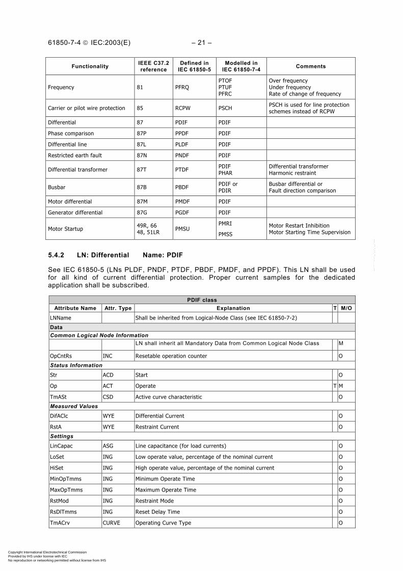
Table 3 – Relation between IEC 61850-5 and IEC 61850-7-4 (this standard)for protection LNs
Functionality IEEE C37.2reference
Defined inIEC 61850-5
Modelled inIEC 61850-7-4 Comments
Transient earthfault PTEF PTEF Use shown in Annex B.1
Directional earth faultwattmetric protection PWDE PSDE Sensitive earth fault protection
Use shown in Annex B.1
Zero speed and underspeed 14 PZSU PZSU
Distance 21 PDIS PDISPSCH
Use one instance per zone.To build line protection schemes
Volt per Hz 24 PVPH PVPH
(Time) Undervoltage 27 PTUV PTUV
Directional power /reversepower 32 PDPR
PDOP
or
PDUP
Directional over powerDirectional under power
Reverse power modelled byPDOP plus directional mode“reverse”
Undercurrent/underpower 37 PUCP PTUCPDUP
UndercurrentUnderpower
Loss of field/Underexcitation 40 PUEX PDUP Directional under power
Reverse phase or phase balancecurrent 46 PPBR PTOC
Time overcurrent (PTOC) withthree-phase information withsequence current as an input oreven ratio of negative andpositive sequence currents
Phase sequence voltage 47 PPBV PTOV Three-phase information andprocessing
Thermal overload 49 PTTR PTTR
Rotor thermal overload 49R PROL PTTR Thermal overload
Stator thermal overload 49S PSOL PTTR Thermal overload
Instantaneous overcurrent orrate of rise 50 PIOC PIOC
AC time overcurrent 51 PTOC PTOC
Voltage controlled/dependenttime overcurrent 51V PVOC PVOC
Power factor 55 PPFR POPFPUPF
Over power factorUnder power factor
(Time) Overvoltage 59 PTOV PTOV
DC-overvoltage 59DC PDOV PTOV Both for DC and AC
Voltage or current balance 60 PVCB PTOVPTOC
Overvoltage or overcurrentregarding the magnitude of thedifference
Earth fault / Ground detection 64 PHIZ PHIZ
Rotor earth fault 64R PREF PTOC Time overcurrent
Stator earth fault 64S PSEF PTOC Time overcurrent
Interturn fault 64W PITF PTOC Time overcurrent
AC directional overcurrent 67 PDOC PTOC Time overcurrent
Directional earth fault 67N PDEF PTOC Time overcurrent
DC time overcurrent 76 PDCO PTOC Time overcurrent for AC and DC
Phase angle or out-of-step 78 PPAM PPAM
Copyright International Electrotechnical Commission Provided by IHS under license with IEC
Not for ResaleNo reproduction or networking permitted without license from IHS
--``````-`-`,,`,,`,`,,`---
61850-7-4 IEC:2003(E) – 21 –
Functionality IEEE C37.2reference
Defined inIEC 61850-5
Modelled inIEC 61850-7-4 Comments
Frequency 81 PFRQPTOFPTUFPFRC
Over frequencyUnder frequencyRate of change of frequency
Carrier or pilot wire protection 85 RCPW PSCH PSCH is used for line protectionschemes instead of RCPW
Differential 87 PDIF PDIF
Phase comparison 87P PPDF PDIF
Differential line 87L PLDF PDIF
Restricted earth fault 87N PNDF PDIF
Differential transformer 87T PTDF PDIFPHAR
Differential transformerHarmonic restraint
Busbar 87B PBDF PDIF orPDIR
Busbar differential orFault direction comparison
Motor differential 87M PMDF PDIF
Generator differential 87G PGDF PDIF
Motor Startup 49R, 6648, 51LR PMSU
PMRI
PMSS
Motor Restart InhibitionMotor Starting Time Supervision
5.4.2 LN: Differential Name: PDIF
See IEC 61850-5 (LNs PLDF, PNDF, PTDF, PBDF, PMDF, and PPDF). This LN shall be usedfor all kind of current differential protection. Proper current samples for the dedicatedapplication shall be subscribed.
PDIF classAttribute Name Attr. Type Explanation T M/O
LNName Shall be inherited from Logical-Node Class (see IEC 61850-7-2)
DataCommon Logical Node Information
LN shall inherit all Mandatory Data from Common Logical Node Class M
OpCntRs INC Resetable operation counter O
Status Information
Str ACD Start O
Op ACT Operate T M
TmASt CSD Active curve characteristic O
Measured Values
DifAClc WYE Differential Current O
RstA WYE Restraint Current O
Settings
LinCapac ASG Line capacitance (for load currents) O
LoSet ING Low operate value, percentage of the nominal current O
HiSet ING High operate value, percentage of the nominal current O
MinOpTmms ING Minimum Operate Time O
MaxOpTmms ING Maximum Operate Time O
RstMod ING Restraint Mode O
RsDlTmms ING Reset Delay Time O
TmACrv CURVE Operating Curve Type O
Copyright International Electrotechnical Commission Provided by IHS under license with IEC
Not for ResaleNo reproduction or networking permitted without license from IHS
--``````-`-`,,`,,`,`,,`---

– 22 – 61850-7-4 IEC:2003(E)
5.4.3 LN: Direction comparison Name: PDIR
For a description of this LN, see IEC 61850-5. The operate decision is based on an agreementof the fault direction signals from all directional fault sensors (for example directional relays)surrounding the fault. The directional comparison for lines is made with PSCH.
PDIR classAttribute Name Attr. Type Explanation T M/O
LNName Shall be inherited from Logical-Node Class (see IEC 61850-7-2)
DataCommon Logical Node Information
LN shall inherit all Mandatory Data from Common Logical Node Class M
OpCntRs INC Resetable operation counter O
Status Information
Str ACD Start (appearance of the first related fault direction) M
Op ACT Operate (decision from all sensors that the surrounded object is faulted) T M
Settings
RsDlTmms ING Reset Delay Time O
5.4.4 LN: Distance Name: PDIS
For a description of this LN, see IEC 61850-5. The phase start value and ground start value areminimum thresholds to release the impedance measurements depending on the distancefunction characteristic given by the algorithm and defined by the settings. The settings replacethe data curve as used for the characteristic on some other protection LNs.
PDIS classAttribute Name Attr. Type Explanation T M/O
LNName Shall be inherited from Logical-Node Class (see IEC 61850-7-2)
DataCommon Logical Node Information
LN shall inherit all Mandatory Data from Common Logical Node Class M
OpCntRs INC Resetable operation counter O
Status Information
Str ACD Start M
Op ACT Operate T M
Settings
PoRch ASG Polar Reach is the diameter of the Mho diagram O
PhStr ASG Phase Start Value O
GndStr ASG Ground Start Value O
DirMod ING Directional Mode O
PctRch ASG Percent Reach O
Ofs ASG Offset O
PctOfs ASG Percent Offset O
RisLod ASG Resistive reach for load area O
AngLod ASG Angle for load area O
TmDlMod SPG Operate Time Delay Mode O
OpDlTmms ING Operate Time Delay O
PhDlMod SPG Operate Time Delay Multiphase Mode O
PhDlTmms ING Operate Time Delay for Multiphase Faults O
GndDlMod SPG Operate Time Delay for Single Phase Ground Mode O
GndDlTmms ING Operate Time Delay for single phase ground faults O
Copyright International Electrotechnical Commission Provided by IHS under license with IEC
Not for ResaleNo reproduction or networking permitted without license from IHS
--``````-`-`,,`,,`,`,,`---

61850-7-4 IEC:2003(E) – 23 –
PDIS classAttribute Name Attr. Type Explanation T M/O
X1 ASG Positive sequence line (reach) reactance O
LinAng ASG Line Angle O
RisGndRch ASG Resistive Ground Reach O
RisPhRch ASG Resistive Phase Reach O
K0Fact ASG Residual Compensation Factor K0 O
K0FactAng ASG Residual Compensation Factor Angle O
RsDlTmms ING Reset Time Delay O
5.4.5 LN: Directional overpower Name: PDOP
For a description of this LN, see IEC 61850-5 (LN PDPR). This LN shall be used for theoverpower part of PDPR. Additionally, PDOP is used to model a reverse overpower function(IEEE device function number 32R, from IEEE 32R.2,1996) when the DirMod is set to reverse.
PDOP classAttribute Name Attr. Type Explanation T M/O
LNName Shall be inherited from Logical-Node Class (see IEC 61850-7-2)
DataCommon Logical Node Information
LN shall inherit all Mandatory Data from Common Logical Node Class M
OpCntRs INC Resetable operation counter O
Status Information
Str ACD Start M
Op ACT Operate T M
Settings
DirMod ING Directional Mode O
StrVal ASG Start Value O
OpDlTmms ING Operate Delay Time O
RsDlTmms ING Reset Delay Time O
5.4.6 LN: Directional underpower Name: PDUP
For a description of this LN, see IEC 61850-5 (LN PDPR). This LN shall be used for theunderpower part of PDPR.
PDUP classAttribute Name Attr. Type Explanation T M/O
LNName Shall be inherited from Logical-Node Class (see IEC 61850-7-2)
DataCommon Logical Node Information
LN shall inherit all Mandatory Data from Common Logical Node Class M
OpCntRs INC Resetable operation counter O
Status Information
Str ACD Start M
Op ACT Operate T M
Settings
StrVal ASG Start Value O
OpDlTmms ING Operate Delay Time O
RsDlTmms ING Reset Delay Time O
DirMod ING Directional Mode O
Copyright International Electrotechnical Commission Provided by IHS under license with IEC
Not for ResaleNo reproduction or networking permitted without license from IHS
--``````-`-`,,`,,`,`,,`---

– 24 – 61850-7-4 IEC:2003(E)
5.4.7 LN: Rate of change of frequency Name: PFRC
For a description of this LN, see IEC 61850-5 (LN PFRQ). This LN shall be used to model therate of frequency change of PFRQ. One instance shall be used per stage.
PFRC classAttribute Name Attr. Type Explanation T M/O
LNName Shall be inherited from Logical-Node Class (see IEC 61850-7-2)
DataCommon Logical Node Information
LN shall inherit all Mandatory Data from Common Logical Node Class M
OpCntRs INC Resetable operation counter O
Status Information
Str ACD Start M
Op ACT Operate T M
BlkV SPS Blocked because of voltage O
Settings
StrVal ASG Start Value df/dt O
BlkVal ASG Voltage Block Value O
OpDlTmms ING Operate Delay Time O
RsDlTmms ING Reset Delay Time O
5.4.8 LN: Harmonic restraint Name: PHAR
This LN shall be used to represent the harmonic restraint data of the transformer differentialprotection (see PDIF) in a dedicated node. There may be multiple instantiations of this LN withdifferent settings, especially with different data HaRst.
PHAR classAttribute Name Attr. Type Explanation T M/O
LNName Shall be inherited from Logical-Node Class (see IEC 61850-7-2)
DataCommon Logical Node Information
LN shall inherit all Mandatory Data from Common Logical Node Class M
OpCntRs INC Resetable operation counter O
Status Information
Str ACD Start (active when restraint is needed) M
Settings
HaRst ING Number of harmonic restrained O
PhStr ASG Start Value O
PhStop ASG Stop Value O
OpDlTmms ING Operate Delay Time O
RsDlTmms ING Reset Delay Time O
Copyright International Electrotechnical Commission Provided by IHS under license with IEC
Not for ResaleNo reproduction or networking permitted without license from IHS
--``````-`-`,,`,,`,`,,`---

61850-7-4 IEC:2003(E) – 25 –
5.4.9 LN: Ground detector Name: PHIZ
For a description of this LN, see IEC 61850-5. This LN shall be used for high-impedanceisolation faults only.
PHIZ classAttribute Name Attr. Type Explanation T M/O
LNName Shall be inherited from Logical-Node Class (see IEC 61850-7-2)
DataCommon Logical Node Information
LN shall inherit all Mandatory Data from Common Logical Node Class M
OpCntRs INC Resetable operation counter O
Status Information
Str ACD Start M
Op ACT Operate T M
Settings
AStr ASG Current Start Value O
VStr ASG Voltage Start Value O
HVStr ASG Third Harmonic Voltage Start Value O
OpDlTmms ING Operate Delay Time O
RsDlTmms ING Reset Delay Time O
5.4.10 LN: Instantaneous overcurrent Name: PIOC
For a description of this LN, see IEC 61850-5. This LN shall be used for instantaneousovercurrent protection only.
PIOC classAttribute Name Attr. Type Explanation T M/O
LNName Shall be inherited from Logical-Node Class (see IEC 61850-7-2)
DataCommon Logical Node Information
LN shall inherit all Mandatory Data from Common Logical Node Class M
OpCntRs INC Resetable operation counter O
Status Information
Str ACD Start O
Op ACT Operate T M
Settings
StrVal ASG Start Value O
5.4.11 LN: Motor restart inhibition Name: PMRI
For a description of this LN, see IEC 61850-5 (LN PMSU). This LN shall be used to model fromLN PMSU the part which protects a motor against thermal overload during start-up in adedicated LN.
PMRI classAttribute Name Attr. Type Explanation T M/O
LNName Shall be inherited from Logical-Node Class (see IEC 61850-7-2)
DataCommon Logical Node Information
LN shall inherit all Mandatory Data from Common Logical Node Class M
OpCntRs INC Resetable operation counter O
Copyright International Electrotechnical Commission Provided by IHS under license with IEC
Not for ResaleNo reproduction or networking permitted without license from IHS
--``````-`-`,,`,,`,`,,`---
– 26 – 61850-7-4 IEC:2003(E)
PMRI classAttribute Name Attr. Type Explanation T M/O
Status Information
Op ACT Operate T O
StrInh SPS Restart inhibited O
StrInhTmm INS Restart Inhibition Time O
Settings
SetA ASG Current setting for motor start-up O
SetTms ING Time Setting for motor start-up O
MaxNumStr ING Maximum number of starts (also for cold starts) O
MaxWrmStr ING Maximum Warm Starts, permissible number of warm starts O
MaxStrTmm ING Time period for the maximum number of starts O
EqTmm ING Temperature Equalisation Time O
InhTmm ING Restart Inhibit Time O
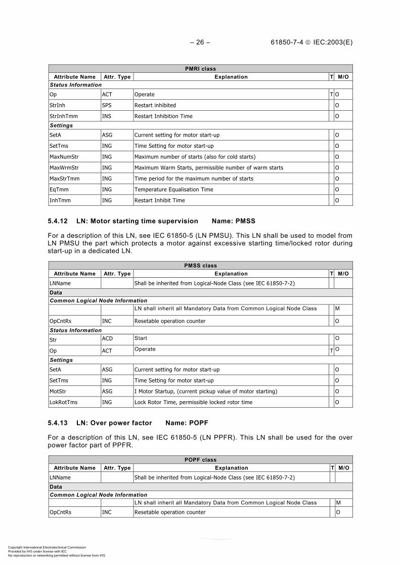
5.4.12 LN: Motor starting time supervision Name: PMSS
For a description of this LN, see IEC 61850-5 (LN PMSU). This LN shall be used to model fromLN PMSU the part which protects a motor against excessive starting time/locked rotor duringstart-up in a dedicated LN.
PMSS classAttribute Name Attr. Type Explanation T M/O
LNName Shall be inherited from Logical-Node Class (see IEC 61850-7-2)
DataCommon Logical Node Information
LN shall inherit all Mandatory Data from Common Logical Node Class M
OpCntRs INC Resetable operation counter O
Status Information
Str ACD Start O
Op ACT Operate T O
Settings
SetA ASG Current setting for motor start-up O
SetTms ING Time Setting for motor start-up O
MotStr ASG I Motor Startup, (current pickup value of motor starting) O
LokRotTms ING Lock Rotor Time, permissible locked rotor time O
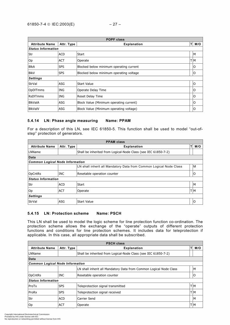
5.4.13 LN: Over power factor Name: POPF
For a description of this LN, see IEC 61850-5 (LN PPFR). This LN shall be used for the overpower factor part of PPFR.
POPF classAttribute Name Attr. Type Explanation T M/O
LNName Shall be inherited from Logical-Node Class (see IEC 61850-7-2)
DataCommon Logical Node Information
LN shall inherit all Mandatory Data from Common Logical Node Class M
OpCntRs INC Resetable operation counter O
Copyright International Electrotechnical Commission Provided by IHS under license with IEC
Not for ResaleNo reproduction or networking permitted without license from IHS
--``````-`-`,,`,,`,`,,`---
61850-7-4 IEC:2003(E) – 27 –
POPF classAttribute Name Attr. Type Explanation T M/O
Status Information
Str ACD Start M
Op ACT Operate T M
BlkA SPS Blocked below minimum operating current O
BlkV SPS Blocked below minimum operating voltage O
Settings
StrVal ASG Start Value O
OpDlTmms ING Operate Delay Time O
RsDlTmms ING Reset Delay Time O
BlkValA ASG Block Value (Minimum operating current) O
BlkValV ASG Block Value (Minimum operating voltage) O
5.4.14 LN: Phase angle measuring Name: PPAM
For a description of this LN, see IEC 61850-5. This function shall be used to model “out-of-step” protection of generators.
PPAM classAttribute Name Attr. Type Explanation T M/O
LNName Shall be inherited from Logical-Node Class (see IEC 61850-7-2)
DataCommon Logical Node Information
LN shall inherit all Mandatory Data from Common Logical Node Class M
OpCntRs INC Resetable operation counter O
Status Information
Str ACD Start M
Op ACT Operate T M
Settings
StrVal ASG Start Value O
5.4.15 LN: Protection scheme Name: PSCH
This LN shall be used to model the logic scheme for line protection function co-ordination. Theprotection scheme allows the exchange of the “operate” outputs of different protectionfunctions and conditions for line protection schemes. It includes data for teleprotection ifapplicable. In this case, all appropriate data shall be subscribed.
PSCH classAttribute Name Attr. Type Explanation T M/O
LNName Shall be inherited from Logical-Node Class (see IEC 61850-7-2)
DataCommon Logical Node Information
LN shall inherit all Mandatory Data from Common Logical Node Class M
OpCntRs INC Resetable operation counter O
Status Information
ProTx SPS Teleprotection signal transmitted T M
ProRx SPS Teleprotection signal received T M
Str ACD Carrier Send M
Op ACT Operate T M
Copyright International Electrotechnical Commission Provided by IHS under license with IEC
Not for ResaleNo reproduction or networking permitted without license from IHS
--``````-`-`,,`,,`,`,,`---

– 28 – 61850-7-4 IEC:2003(E)
PSCH classAttribute Name Attr. Type Explanation T M/O
CarRx ACT Carrier received after unblock logic O
LosOfGrd SPS Loss of guard O
Echo ACT Echo signal from weak end infeed function O
WeiOp ACT Operate signal from weak end infeed function O
RvABlk ACT Block signal from current reversal function O
GrdRx SPS Guard Received O
Settings
SchTyp ING Scheme Type O
OpDlTmms ING Operate Delay Time O
CrdTmms ING Co-ordination timer for blocking scheme O
DurTmms ING Minimum duration of carrier send signal O
UnBlkMod ING Unblock function mode for scheme type O
SecTmms ING Pickup security timer on loss of carrier guard signal O
WeiMod ING Mode of weak end infeed function O
WeiTmms ING Co-ordination time for weak end infeed function O
PPVVal ASG Voltage level for weak end infeed function – phase-phase O
PhGndVal ASG Voltage level for weak end infeed function – phase-ground O
RvAMod ING Mode of current reversal function O
RvATmms ING Pickup time for current reversal logic O
RvRsTmms ING Delay time for reset of current reversal output O
5.4.16 LN: Sensitive directional earthfault Name: PSDE
For a general description of directed earth fault protection, see IEC 61850-5. This LN is usedfor directional earthfault handling in compensated and isolated networks. The use of “operate”is optional and depends both on protection philosophy and on instrument transformer capabi-lities. For compensated networks, this function is often called wattmetric directional earthfault.The very high accuracy needed for fault current measurement in compensated networks mayrequire phase angle compensation. This shall be realised by the related LN TCTR.
PSDE classAttribute Name Attr. Type Explanation T M/O
LNName Shall be inherited from Logical-Node Class (see IEC 61850-7-2)
DataCommon Logical Node Information
LN shall inherit all Mandatory Data from Common Logical Node Class M
OpCntRs INC Resetable operation counter O
Status Information
Str ACD Start M
Op ACT Operate T O
Settings
Ang ASG Angle between voltage (U0) and current (I0) O
GndStr ASG Ground Start Value (3 U0) O
GndOp ASG Ground Operate Value (3 I0) O
StrDlTmms ING Start Delay Time O
OpDlTmms ING Operate Delay Time O
DirMod ING Directional Mode O
Copyright International Electrotechnical Commission Provided by IHS under license with IEC
Not for ResaleNo reproduction or networking permitted without license from IHS
--``````-`-`,,`,,`,`,,`---
61850-7-4 IEC:2003(E) – 29 –
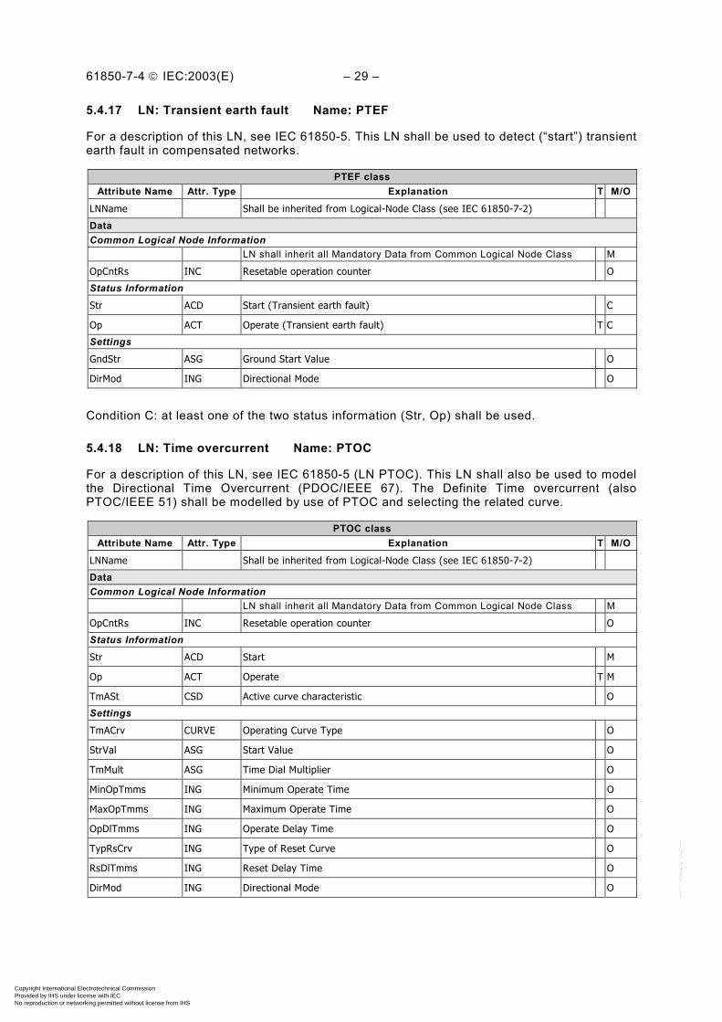
5.4.17 LN: Transient earth fault Name: PTEF
For a description of this LN, see IEC 61850-5. This LN shall be used to detect (“start”) transientearth fault in compensated networks.
PTEF classAttribute Name Attr. Type Explanation T M/O
LNName Shall be inherited from Logical-Node Class (see IEC 61850-7-2)
DataCommon Logical Node Information
LN shall inherit all Mandatory Data from Common Logical Node Class M
OpCntRs INC Resetable operation counter O
Status Information
Str ACD Start (Transient earth fault) C
Op ACT Operate (Transient earth fault) T C
Settings
GndStr ASG Ground Start Value O
DirMod ING Directional Mode O
Condition C: at least one of the two status information (Str, Op) shall be used.
5.4.18 LN: Time overcurrent Name: PTOC
For a description of this LN, see IEC 61850-5 (LN PTOC). This LN shall also be used to modelthe Directional Time Overcurrent (PDOC/IEEE 67). The Definite Time overcurrent (alsoPTOC/IEEE 51) shall be modelled by use of PTOC and selecting the related curve.
PTOC classAttribute Name Attr. Type Explanation T M/O
LNName Shall be inherited from Logical-Node Class (see IEC 61850-7-2)
DataCommon Logical Node Information
LN shall inherit all Mandatory Data from Common Logical Node Class M
OpCntRs INC Resetable operation counter O
Status Information
Str ACD Start M
Op ACT Operate T M
TmASt CSD Active curve characteristic O
Settings
TmACrv CURVE Operating Curve Type O
StrVal ASG Start Value O
TmMult ASG Time Dial Multiplier O
MinOpTmms ING Minimum Operate Time O
MaxOpTmms ING Maximum Operate Time O
OpDlTmms ING Operate Delay Time O
TypRsCrv ING Type of Reset Curve O
RsDlTmms ING Reset Delay Time O
DirMod ING Directional Mode O
Copyright International Electrotechnical Commission Provided by IHS under license with IEC
Not for ResaleNo reproduction or networking permitted without license from IHS
--``````-`-`,,`,,`,`,,`---

– 30 – 61850-7-4 IEC:2003(E)
5.4.19 LN: Overfrequency Name: PTOF
For a description of this LN, see IEC 61850-5 (LN PFRQ). This LN shall be used to model theovercurrent part of PFRQ. One instance shall be used per stage.
PTOF classAttribute Name Attr. Type Explanation T M/O
LNName Shall be inherited from Logical-Node Class (see IEC 61850-7-2)
DataCommon Logical Node Information
LN shall inherit all Mandatory Data from Common Logical Node Class M
OpCntRs INC Resetable operation counter O
Status Information
Str ACD Start M
Op ACT Operate T M
BlkV SPS Blocked because of voltage O
Settings
StrVal ASG Start Value (frequency) O
BlkVal ASG Voltage Block Value O
OpDlTmms ING Operate Delay Time O
RsDlTmms ING Reset Delay Time O
5.4.20 LN: Overvoltage Name: PTOV
For a description of this LN, see IEC 61850-5. For some applications such as transformer star-point or delta supervision, “operate” may not be used.
PTOV classAttribute Name Attr. Type Explanation T M/O
LNName Shall be inherited from Logical-Node Class (see IEC 61850-7-2)
DataCommon Logical Node Information
LN shall inherit all Mandatory Data from Common Logical Node Class M
OpCntRs INC Resetable operation counter O
Status Information
Str ACD Start M
Op ACT Operate T O
TmVSt CSD Active curve characteristic O
Settings
TmVCrv CURVE Operating Curve Type O
StrVal ASG Start Value O
TmMult ASG Time Dial Multiplier O
MinOpTmms ING Minimum Operate Time O
MaxOpTmms ING Maximum Operate Time O
OpDlTmms ING Operate Delay Time O
RsDlTmms ING Reset Delay Time O
5.4.21 LN: Protection trip conditioning Name: PTRC
This LN shall be used to connect the “operate” outputs of one or more protection functions to acommon “trip” to be transmitted to XCBR. In addition or alternatively, any combination of“operate” outputs of the protection functions may be combined to a new “operate” of PTRC.
Copyright International Electrotechnical Commission Provided by IHS under license with IEC
Not for ResaleNo reproduction or networking permitted without license from IHS
--``````-`-`,,`,,`,`,,`---
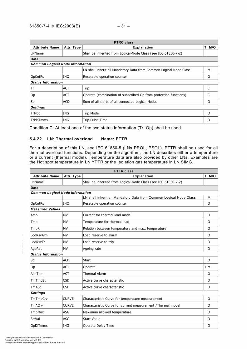
61850-7-4 IEC:2003(E) – 31 –
PTRC classAttribute Name Attr. Type Explanation T M/O
LNName Shall be inherited from Logical-Node Class (see IEC 61850-7-2)
DataCommon Logical Node Information
LN shall inherit all Mandatory Data from Common Logical Node Class M
OpCntRs INC Resetable operation counter O
Status Information
Tr ACT Trip C
Op ACT Operate (combination of subscribed Op from protection functions) C
Str ACD Sum of all starts of all connected Logical Nodes O
Settings
TrMod ING Trip Mode O
TrPlsTmms ING Trip Pulse Time O
Condition C: At least one of the two status information (Tr, Op) shall be used.
5.4.22 LN: Thermal overload Name: PTTR
For a description of this LN, see IEC 61850-5 (LNs PROL, PSOL). PTTR shall be used for allthermal overload functions. Depending on the algorithm, the LN describes either a temperatureor a current (thermal model). Temperature data are also provided by other LNs. Examples arethe Hot spot temperature in LN YPTR or the Isolation gas temperature in LN SIMG.
PTTR classAttribute Name Attr. Type Explanation T M/O
LNName Shall be inherited from Logical-Node Class (see IEC 61850-7-2)
DataCommon Logical Node Information
LN shall inherit all Mandatory Data from Common Logical Node Class M
OpCntRs INC Resetable operation counter O
Measured Values
Amp MV Current for thermal load model O
Tmp MV Temperature for thermal load O
TmpRl MV Relation between temperature and max. temperature O
LodRsvAlm MV Load reserve to alarm O
LodRsvTr MV Load reserve to trip O
AgeRat MV Ageing rate O
Status Information
Str ACD Start O
Op ACT Operate T M
AlmThm ACT Thermal Alarm O
TmTmpSt CSD Active curve characteristic O
TmASt CSD Active curve characteristic O
Settings
TmTmpCrv CURVE Characteristic Curve for temperature measurement O
TmACrv CURVE Characteristic Curve for current measurement /Thermal model O
TmpMax ASG Maximum allowed temperature O
StrVal ASG Start Value O
OpDlTmms ING Operate Delay Time O
Copyright International Electrotechnical Commission Provided by IHS under license with IEC
Not for ResaleNo reproduction or networking permitted without license from IHS
--``````-`-`,,`,,`,`,,`---
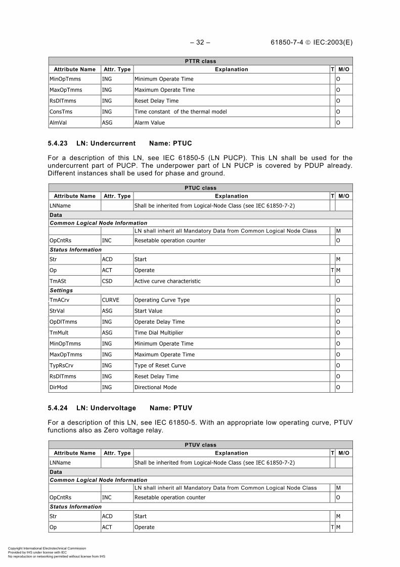
– 32 – 61850-7-4 IEC:2003(E)
PTTR classAttribute Name Attr. Type Explanation T M/O
MinOpTmms ING Minimum Operate Time O
MaxOpTmms ING Maximum Operate Time O
RsDlTmms ING Reset Delay Time O
ConsTms ING Time constant of the thermal model O
AlmVal ASG Alarm Value O
5.4.23 LN: Undercurrent Name: PTUC
For a description of this LN, see IEC 61850-5 (LN PUCP). This LN shall be used for theundercurrent part of PUCP. The underpower part of LN PUCP is covered by PDUP already.Different instances shall be used for phase and ground.
PTUC classAttribute Name Attr. Type Explanation T M/O
LNName Shall be inherited from Logical-Node Class (see IEC 61850-7-2)
DataCommon Logical Node Information
LN shall inherit all Mandatory Data from Common Logical Node Class M
OpCntRs INC Resetable operation counter O
Status Information
Str ACD Start M
Op ACT Operate T M
TmASt CSD Active curve characteristic O
Settings
TmACrv CURVE Operating Curve Type O
StrVal ASG Start Value O
OpDlTmms ING Operate Delay Time O
TmMult ASG Time Dial Multiplier O
MinOpTmms ING Minimum Operate Time O
MaxOpTmms ING Maximum Operate Time O
TypRsCrv ING Type of Reset Curve O
RsDlTmms ING Reset Delay Time O
DirMod ING Directional Mode O
5.4.24 LN: Undervoltage Name: PTUV
For a description of this LN, see IEC 61850-5. With an appropriate low operating curve, PTUVfunctions also as Zero voltage relay.
PTUV classAttribute Name Attr. Type Explanation T M/O
LNName Shall be inherited from Logical-Node Class (see IEC 61850-7-2)
DataCommon Logical Node Information
LN shall inherit all Mandatory Data from Common Logical Node Class M
OpCntRs INC Resetable operation counter O
Status Information
Str ACD Start M
Op ACT Operate T M
Copyright International Electrotechnical Commission Provided by IHS under license with IEC
Not for ResaleNo reproduction or networking permitted without license from IHS
--``````-`-`,,`,,`,`,,`---
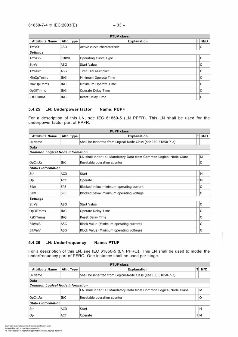
61850-7-4 IEC:2003(E) – 33 –
PTUV classAttribute Name Attr. Type Explanation T M/O
TmVSt CSD Active curve characteristic O
Settings
TmVCrv CURVE Operating Curve Type O
StrVal ASG Start Value O
TmMult ASG Time Dial Multiplier O
MinOpTmms ING Minimum Operate Time O
MaxOpTmms ING Maximum Operate Time O
OpDlTmms ING Operate Delay Time O
RsDlTmms ING Reset Delay Time O
5.4.25 LN: Underpower factor Name: PUPF
For a description of this LN, see IEC 61850-5 (LN PPFR). This LN shall be used for theunderpower factor part of PPFR.
PUPF classAttribute Name Attr. Type Explanation T M/O
LNName Shall be inherited from Logical-Node Class (see IEC 61850-7-2)
DataCommon Logical Node Information
LN shall inherit all Mandatory Data from Common Logical Node Class M
OpCntRs INC Resetable operation counter O
Status Information
Str ACD Start M
Op ACT Operate T M
BlkA SPS Blocked below minimum operating current O
BlkV SPS Blocked below minimum operating voltage O
Settings
StrVal ASG Start Value O
OpDlTmms ING Operate Delay Time O
RsDlTmms ING Reset Delay Time O
BlkValA ASG Block Value (Minimum operating current) O
BlkValV ASG Block Value (Minimum operating voltage) O
5.4.26 LN: Underfrequency Name: PTUF
For a description of this LN, see IEC 61850-5 (LN PFRQ). This LN shall be used to model theunderfrequency part of PFRQ. One instance shall be used per stage.
PTUF classAttribute Name Attr. Type Explanation T M/O
LNName Shall be inherited from Logical-Node Class (see IEC 61850-7-2)
DataCommon Logical Node Information
LN shall inherit all Mandatory Data from Common Logical Node Class M
OpCntRs INC Resetable operation counter O
Status Information
Str ACD Start M
Op ACT Operate T M
Copyright International Electrotechnical Commission Provided by IHS under license with IEC
Not for ResaleNo reproduction or networking permitted without license from IHS
--``````-`-`,,`,,`,`,,`---

– 34 – 61850-7-4 IEC:2003(E)
PTUF classAttribute Name Attr. Type Explanation T M/O
BlkV SPS Blocked because of voltage O
Settings
StrVal ASG Start Value (frequency) O
BlkVal ASG Voltage Block Value O
OpDlTmms ING Operate Delay Time O
RsDlTmms ING Reset Delay Time O
5.4.27 LN: Voltage controlled time overcurrent Name: PVOC
For a description of this LN, see IEC 61850-5.
PVOC classAttribute Name Attr. Type Explanation T M/O
LNName Shall be inherited from Logical-Node Class (see IEC 61850-7-2)
DataCommon Logical Node Information
LN shall inherit all Mandatory Data from Common Logical Node Class M
OpCntRs INC Resetable operation counter O
Status Information
Str ACD Start M
Op ACT Operate T M
AVSt CSD Active curve characteristic O
TmASt CSD Active curve characteristic O
Settings
AVCrv CURVE Operating Curve Type (for voltage controlled current curve) O
TmACrv CURVE Operating Curve Type (for current) O
TmMult ASG Time Dial Multiplier O
MinOpTmms ING Minimum Operate Time O
MaxOpTmms ING Maximum Operate Time O
OpDlTmms ING Operate Delay Time O
TypRsCrv ING Type of Reset Curve O
RsDlTmms ING Reset Delay Time O
5.4.28 LN: Volts per Hz Name: PVPH
For a description of this LN, see IEC 61850-5. One instance of PVPH shall be used perprotection stage.
PVPH classAttribute Name Attr. Type Explanation T M/O
LNName Shall be inherited from Logical-Node Class (see IEC 61850-7-2)
DataCommon Logical Node Information
LN shall inherit all Mandatory Data from Common Logical Node Class M
OpCntRs INC Resetable operation counter O
Status Information
Str ACD Start M
Op ACT Operate T M
VHzSt CSD Active curve characteristic O
Copyright International Electrotechnical Commission Provided by IHS under license with IEC
Not for ResaleNo reproduction or networking permitted without license from IHS
--``````-`-`,,`,,`,`,,`---

61850-7-4 IEC:2003(E) – 35 –
PVPH classAttribute Name Attr. Type Explanation T M/O
Settings
VHzCrv CURVE Operating Curve Type O
StrVal ASG Volts per hertz Start Value O
OpDlTmms ING Operate Delay Time O
TypRsCrv ING Type of Reset Curve O
RsDlTmms ING Reset Delay Time O
TmMult ASG Time Dial Multiplier O
MinOpTmms ING Minimum Operate Time O
MaxOpTmms ING Maximum Operate Time O
5.4.29 LN: Zero speed or underspeed Name: PZSU
For a description of this LN, see IEC 61850-5.
PZSU classAttribute Name Attr. Type Explanation T M/O
LNName Shall be inherited from Logical-Node Class (see IEC 61850-7-2)
DataCommon Logical Node Information
LN shall inherit all Mandatory Data from Common Logical Node Class M
OpCntRs INC Resetable operation counter O
Status Information
Str ACD Start M
Op ACT Operate T M
Settings
StrVal ASG Start Value (Speed) O
OpDlTmms ING Operate Delay Time O
RsDlTmms ING Reset Delay Time O
5.5 Logical Nodes for protection related functions LN Group: R
5.5.1 Modelling Remarks
Table 4 – Relation between IEC 61850-5 and IEC 61850-7-4 for protection related LNs
Functionality IEEEreference
Defined inIEC 61850-5
by LN
Modelled inIEC 61850-7-4
by LNComments
Carrier or pilot line wireprotection 85 RCPW PSCH PSCH is used for line protection
schemes instead of RCPW
Directional element RDIR Directional element for modellingdirected protection with Pxyz nodes
Disturbance recording(acquisition) RDRE
RDRE
RADR
RBDR
Basic functionality
Analogue channel
Binary channel
Others R… R… 1:1 Relationship
Copyright International Electrotechnical Commission Provided by IHS under license with IEC
Not for ResaleNo reproduction or networking permitted without license from IHS
--``````-`-`,,`,,`,`,,`---

– 36 – 61850-7-4 IEC:2003(E)
5.5.2 LN: Disturbance recorder function Name: RDRE
For consistent modelling, the disturbance recorder function described as a requirement in IEC61850-5 is decomposed into one LN class for analogue channels (RADR) and another LN classfor binary channels (RBDR). The output refers to the “IEEE Standard Format for Transient DataExchange (COMTRADE) for Power Systems” (IEC 60255-24). Disturbance recorders arelogical devices built up with one instance of LN RADR or LN RBDR per channel. Since thecontent of Logical Devices (LD) are not standardised, other LNs may be inside the LD“Disturbance recorder” if applicable. All enabled channels are included in the recording,independently of the trigger mode (TrgMod).
RDRE classAttribute Name Attr. Type Explanation T M/O
LNName Shall be inherited from Logical-Node Class (see IEC 61850-7-2)
DataCommon Logical Node Information
LN shall inherit all Mandatory Data from Common Logical Node Class M
OpCntRs INC Resetable operation counter O
Controls
RcdTrg SPC Trigger recorder O
MemRs SPC Reset recorder memory T O
MemClr SPC Clear Memory T O
Status Information
RcdMade SPS Recording made M
FltNum INS Fault Number M
GriFltNum INS Grid Fault Number O
RcdStr SPS Recording started O
MemUsed INS Memory used in % O
Settings
TrgMod ING Trigger mode (internal trigger, external or both) O
LevMod ING Level Trigger Mode O
PreTmms ING Pre-trigger time O
PstTmms ING Post-trigger time O
MemFull ING Memory full level O
MaxNumRcd ING Maximum number of records O
ReTrgMod ING Retrigger Mode O
PerTrgTms ING Periodic trigger time in s O
ExclTmms ING Exclusion time O
OpMod ING Operation mode (Saturation, Overwrite) O
NOTE 1 The trigger modes (TrgMod) of RDRE, RADR and RBDR are not independent. If the trigger mode ofRDRE is external, the trigger modes of RADR and RBDR may be external (no extension of trigger possibilities) orinternal (extension of the external trigger mode). If the trigger mode of RDRE is internal, the trigger modes of RADRand RBDR should also be internal because otherwise, no trigger possibility is provided.
NOTE 2 The source of the external trigger is a local issue. It may be a contact or a signal from another logicalnode.
NOTE 3 The source of the internal trigger is an event detected by the supervision of the channel. It may, foranalogue channels, be a limit violation or it may, for binary channels, be a status change. The trigger levels(High/Low) for analogue channels for internal triggering have to be set per channel.
Copyright International Electrotechnical Commission Provided by IHS under license with IEC
Not for ResaleNo reproduction or networking permitted without license from IHS
--``````-`-`,,`,,`,`,,`---
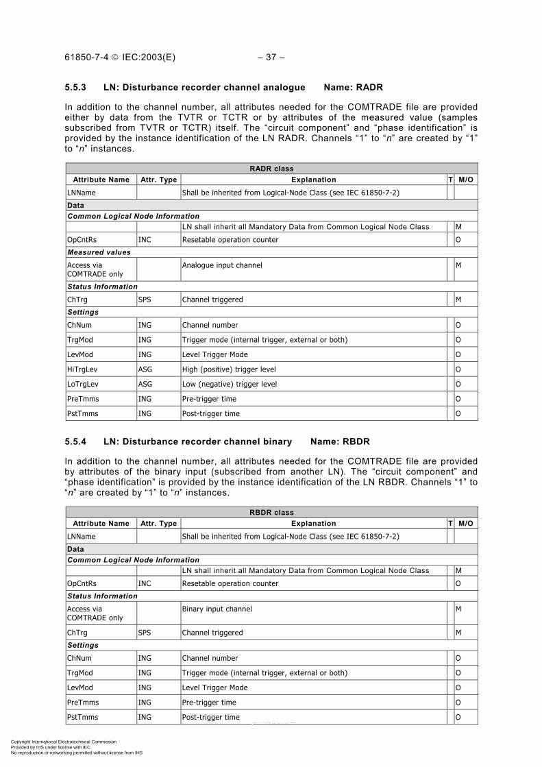
61850-7-4 IEC:2003(E) – 37 –
5.5.3 LN: Disturbance recorder channel analogue Name: RADR
In addition to the channel number, all attributes needed for the COMTRADE file are providedeither by data from the TVTR or TCTR or by attributes of the measured value (samplessubscribed from TVTR or TCTR) itself. The “circuit component” and “phase identification” isprovided by the instance identification of the LN RADR. Channels “1” to “n” are created by “1”to “n” instances.
RADR classAttribute Name Attr. Type Explanation T M/O
LNName Shall be inherited from Logical-Node Class (see IEC 61850-7-2)
DataCommon Logical Node Information
LN shall inherit all Mandatory Data from Common Logical Node Class M
OpCntRs INC Resetable operation counter O
Measured values
Access viaCOMTRADE only
Analogue input channel M
Status Information
ChTrg SPS Channel triggered M
Settings
ChNum ING Channel number O
TrgMod ING Trigger mode (internal trigger, external or both) O
LevMod ING Level Trigger Mode O
HiTrgLev ASG High (positive) trigger level O
LoTrgLev ASG Low (negative) trigger level O
PreTmms ING Pre-trigger time O
PstTmms ING Post-trigger time O
5.5.4 LN: Disturbance recorder channel binary Name: RBDR
In addition to the channel number, all attributes needed for the COMTRADE file are providedby attributes of the binary input (subscribed from another LN). The “circuit component” and“phase identification” is provided by the instance identification of the LN RBDR. Channels “1” to“n” are created by “1” to “n” instances.
RBDR classAttribute Name Attr. Type Explanation T M/O
LNName Shall be inherited from Logical-Node Class (see IEC 61850-7-2)
DataCommon Logical Node Information
LN shall inherit all Mandatory Data from Common Logical Node Class M
OpCntRs INC Resetable operation counter O
Status Information
Access viaCOMTRADE only
Binary input channel M
ChTrg SPS Channel triggered M
Settings
ChNum ING Channel number O
TrgMod ING Trigger mode (internal trigger, external or both) O
LevMod ING Level Trigger Mode O
PreTmms ING Pre-trigger time O
PstTmms ING Post-trigger time O
Copyright International Electrotechnical Commission Provided by IHS under license with IEC
Not for ResaleNo reproduction or networking permitted without license from IHS
--``````-`-`,,`,,`,`,,`---

– 38 – 61850-7-4 IEC:2003(E)
5.5.5 LN: Disturbance record handling Name: RDRS
For a description of this LN, see IEC 61850-5. This LN shall handle the disturbance recordsacquired by some local function. This LN is normally located at station level.
RDRS classAttribute Name Attr. Type Explanation T M/O
LNName Shall be inherited from Logical-Node Class (see IEC 61850-7-2)
DataCommon Logical Node Information
LN shall inherit all Mandatory Data from Common Logical Node Class MControls
AutoUpLod SPC Automatic upload O
DltRcd SPC Delete record O
5.5.6 LN: Breaker failure Name: RBRF
For a description of this LN, see IEC 61850-5.
RBRF classAttribute Name Attr. Type Explanation T M/O
LNName Shall be inherited from Logical-Node Class (see IEC 61850-7-2)
DataCommon Logical Node Information
LN shall inherit all Mandatory Data from Common Logical Node Class M
OpCntRs INC Resetable operation counter O
Status Information
Str ACD Start, timer running O
OpEx ACT Breaker failure trip (“external trip”) T C
OpIn ACT Operate, retrip (“internal trip”) T C
Settings
FailMod ING Breaker Failure Detection Mode (current, breaker status, both, other) O
FailTmms ING Breaker Failure Time Delay for bus bar trip O
SPlTrTmms ING Single Pole Retrip Time Delay O
TPTrTmms ING Three Pole Retrip Time Delay O
DetValA ASG Current Detector Value O
ReTrMod ING Retrip Mode O
Condition C: At least one of either data shall be used depending on the applied trippingschema.
5.5.7 LN: Directional element Name: RDIR
This LN shall be used to represent all directional Data in a dedicated LN used for directionalrelay settings. The protection function itself is modelled by the dedicated protection LN. LNRDIR may be used with functions 21, 32 or 67 according to IEEE device function numberdesignation.
RDIR classAttribute Name Attr. Type Explanation T M/O
LNName Shall be inherited from Logical-Node Class (see IEC 61850-7-2)
DataCommon Logical Node Information
LN shall inherit all Mandatory Data from Common Logical Node Class MStatus Information
Dir ACD Direction M
Copyright International Electrotechnical Commission Provided by IHS under license with IEC
Not for ResaleNo reproduction or networking permitted without license from IHS
--``````-`-`,,`,,`,`,,`---
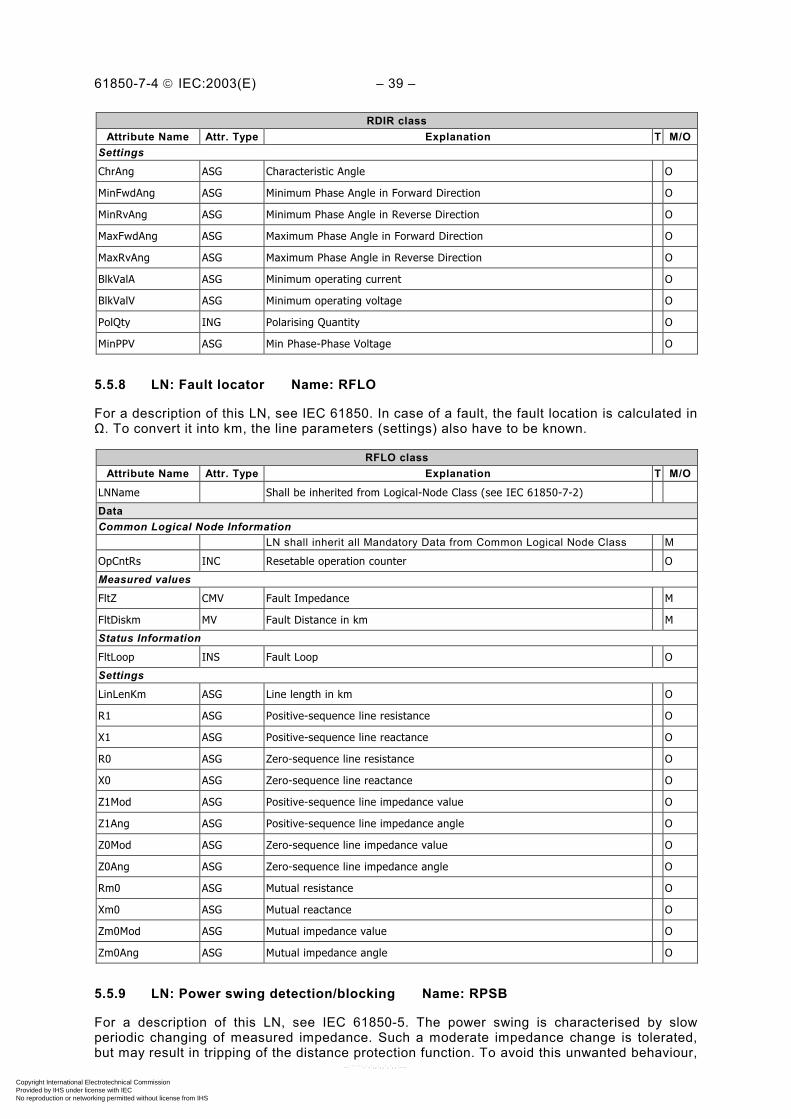
61850-7-4 IEC:2003(E) – 39 –
RDIR classAttribute Name Attr. Type Explanation T M/O
Settings
ChrAng ASG Characteristic Angle O
MinFwdAng ASG Minimum Phase Angle in Forward Direction O
MinRvAng ASG Minimum Phase Angle in Reverse Direction O
MaxFwdAng ASG Maximum Phase Angle in Forward Direction O
MaxRvAng ASG Maximum Phase Angle in Reverse Direction O
BlkValA ASG Minimum operating current O
BlkValV ASG Minimum operating voltage O
PolQty ING Polarising Quantity O
MinPPV ASG Min Phase-Phase Voltage O
5.5.8 LN: Fault locator Name: RFLO
For a description of this LN, see IEC 61850. In case of a fault, the fault location is calculated inΩ. To convert it into km, the line parameters (settings) also have to be known.
RFLO classAttribute Name Attr. Type Explanation T M/O
LNName Shall be inherited from Logical-Node Class (see IEC 61850-7-2)
DataCommon Logical Node Information
LN shall inherit all Mandatory Data from Common Logical Node Class M
OpCntRs INC Resetable operation counter O
Measured values
FltZ CMV Fault Impedance M
FltDiskm MV Fault Distance in km M
Status Information
FltLoop INS Fault Loop O
Settings
LinLenKm ASG Line length in km O
R1 ASG Positive-sequence line resistance O
X1 ASG Positive-sequence line reactance O
R0 ASG Zero-sequence line resistance O
X0 ASG Zero-sequence line reactance O
Z1Mod ASG Positive-sequence line impedance value O
Z1Ang ASG Positive-sequence line impedance angle O
Z0Mod ASG Zero-sequence line impedance value O
Z0Ang ASG Zero-sequence line impedance angle O
Rm0 ASG Mutual resistance O
Xm0 ASG Mutual reactance O
Zm0Mod ASG Mutual impedance value O
Zm0Ang ASG Mutual impedance angle O
5.5.9 LN: Power swing detection/blocking Name: RPSB
For a description of this LN, see IEC 61850-5. The power swing is characterised by slowperiodic changing of measured impedance. Such a moderate impedance change is tolerated,but may result in tripping of the distance protection function. To avoid this unwanted behaviour,
Copyright International Electrotechnical Commission Provided by IHS under license with IEC
Not for ResaleNo reproduction or networking permitted without license from IHS
--``````-`-`,,`,,`,`,,`---
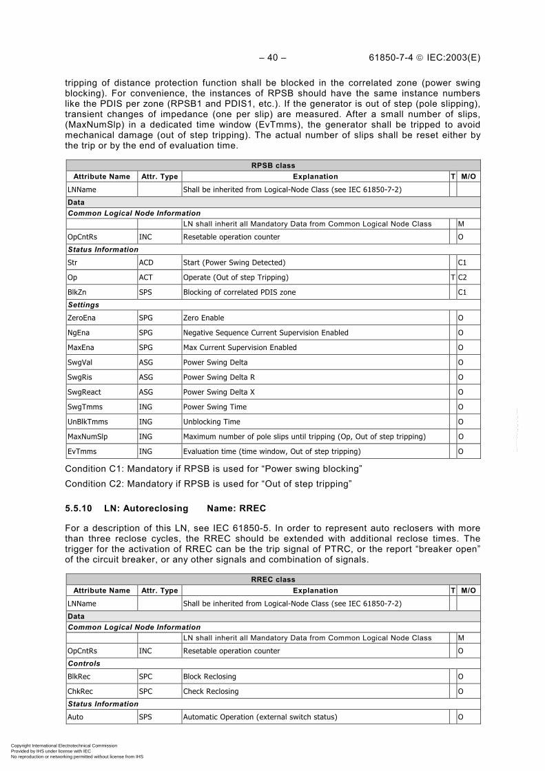
– 40 – 61850-7-4 IEC:2003(E)
tripping of distance protection function shall be blocked in the correlated zone (power swingblocking). For convenience, the instances of RPSB should have the same instance numberslike the PDIS per zone (RPSB1 and PDIS1, etc.). If the generator is out of step (pole slipping),transient changes of impedance (one per slip) are measured. After a small number of slips,(MaxNumSlp) in a dedicated time window (EvTmms), the generator shall be tripped to avoidmechanical damage (out of step tripping). The actual number of slips shall be reset either bythe trip or by the end of evaluation time.
RPSB classAttribute Name Attr. Type Explanation T M/O
LNName Shall be inherited from Logical-Node Class (see IEC 61850-7-2)
DataCommon Logical Node Information
LN shall inherit all Mandatory Data from Common Logical Node Class M
OpCntRs INC Resetable operation counter O
Status Information
Str ACD Start (Power Swing Detected) C1
Op ACT Operate (Out of step Tripping) T C2
BlkZn SPS Blocking of correlated PDIS zone C1
Settings
ZeroEna SPG Zero Enable O
NgEna SPG Negative Sequence Current Supervision Enabled O
MaxEna SPG Max Current Supervision Enabled O
SwgVal ASG Power Swing Delta O
SwgRis ASG Power Swing Delta R O
SwgReact ASG Power Swing Delta X O
SwgTmms ING Power Swing Time O
UnBlkTmms ING Unblocking Time O
MaxNumSlp ING Maximum number of pole slips until tripping (Op, Out of step tripping) O
EvTmms ING Evaluation time (time window, Out of step tripping) O
Condition C1: Mandatory if RPSB is used for “Power swing blocking”Condition C2: Mandatory if RPSB is used for “Out of step tripping”
5.5.10 LN: Autoreclosing Name: RREC
For a description of this LN, see IEC 61850-5. In order to represent auto reclosers with morethan three reclose cycles, the RREC should be extended with additional reclose times. Thetrigger for the activation of RREC can be the trip signal of PTRC, or the report “breaker open”of the circuit breaker, or any other signals and combination of signals.
RREC classAttribute Name Attr. Type Explanation T M/O
LNName Shall be inherited from Logical-Node Class (see IEC 61850-7-2)
DataCommon Logical Node Information
LN shall inherit all Mandatory Data from Common Logical Node Class M
OpCntRs INC Resetable operation counter O
Controls
BlkRec SPC Block Reclosing O
ChkRec SPC Check Reclosing O
Status Information
Auto SPS Automatic Operation (external switch status) O
Copyright International Electrotechnical Commission Provided by IHS under license with IEC
Not for ResaleNo reproduction or networking permitted without license from IHS
--``````-`-`,,`,,`,`,,`---
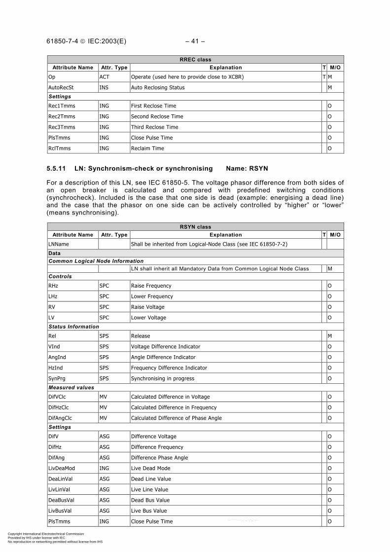
61850-7-4 IEC:2003(E) – 41 –
RREC classAttribute Name Attr. Type Explanation T M/O
Op ACT Operate (used here to provide close to XCBR) T M
AutoRecSt INS Auto Reclosing Status M
Settings
Rec1Tmms ING First Reclose Time O
Rec2Tmms ING Second Reclose Time O
Rec3Tmms ING Third Reclose Time O
PlsTmms ING Close Pulse Time O
RclTmms ING Reclaim Time O
5.5.11 LN: Synchronism-check or synchronising Name: RSYN
For a description of this LN, see IEC 61850-5. The voltage phasor difference from both sides ofan open breaker is calculated and compared with predefined switching conditions(synchrocheck). Included is the case that one side is dead (example: energising a dead line)and the case that the phasor on one side can be actively controlled by “higher” or “lower”(means synchronising).
RSYN classAttribute Name Attr. Type Explanation T M/O
LNName Shall be inherited from Logical-Node Class (see IEC 61850-7-2)
DataCommon Logical Node Information
LN shall inherit all Mandatory Data from Common Logical Node Class MControls
RHz SPC Raise Frequency O
LHz SPC Lower Frequency O
RV SPC Raise Voltage O
LV SPC Lower Voltage O
Status Information
Rel SPS Release M
VInd SPS Voltage Difference Indicator O
AngInd SPS Angle Difference Indicator O
HzInd SPS Frequency Difference Indicator O
SynPrg SPS Synchronising in progress O
Measured values
DifVClc MV Calculated Difference in Voltage O
DifHzClc MV Calculated Difference in Frequency O
DifAngClc MV Calculated Difference of Phase Angle O
Settings
DifV ASG Difference Voltage O
DifHz ASG Difference Frequency O
DifAng ASG Difference Phase Angle O
LivDeaMod ING Live Dead Mode O
DeaLinVal ASG Dead Line Value O
LivLinVal ASG Live Line Value O
DeaBusVal ASG Dead Bus Value O
LivBusVal ASG Live Bus Value O
PlsTmms ING Close Pulse Time O
Copyright International Electrotechnical Commission Provided by IHS under license with IEC
Not for ResaleNo reproduction or networking permitted without license from IHS
--``````-`-`,,`,,`,`,,`---

– 42 – 61850-7-4 IEC:2003(E)
RSYN classAttribute Name Attr. Type Explanation T M/O
BkrTmms ING Closing time of breaker O
5.6 Logical Nodes for control LN Group: C
5.6.1 Modelling remarks
Table 5 – Relation between IEC 61850-5 and IEC 61850-7-4 for control LNs
FunctionalityDefined in
IEC 61850-5by LN
Modelled inIEC 61850-7-4
by LNComments
Transformer incl. cooling YPTR CCGR Dedicated cooling group control split off fromYPTR
Tap changer controller CTCC ATCC Automatic tap changer controller
5.6.2 LN: Alarm handling Name: CALH
For a description of this LN, see IEC 61850-5. Individual alarms are generated in the corres-ponding logical nodes, for example metering alarms are found in MMXU or MMTR, etc. CALHallows the creation of group warnings and alarms. The individual alarms, which are used tocalculate the group alarms/warnings, are subscribed from elsewhere. The calculation is a localissue.
CALH classAttribute Name Attr. Type Explanation T M/O
LNName Shall be inherited from Logical-Node Class (see IEC 61850-7-2)
DataCommon Logical Node Information
LN shall inherit all Mandatory Data from Common Logical Node Class M
Status Information
GrAlm SPS Group alarm M
GrWrn SPS Group warning O
AlmLstOv SPS Alarm list overflow O
5.6.3 LN: Cooling group control Name: CCGR
This LN class shall be used to control the cooling equipment. One instance per cooling groupshall be used.
CCGR classAttribute Name Attr. Type Explanation T M/O
LNName Shall be inherited from Logical-Node Class (see IEC 61850-7-2)
DataCommon Logical Node Information
LN shall inherit all Mandatory Data from Common Logical Node Class MEEHealth INS External equipment health O
EEName DPL External equipment name plate O
OpTmh INS Operation time OMeasured valuesEnvTmp MV Temperature of environment O
OilTmpIn MV Oil temperature cooler in O
OilTmpOut MV Oil temperature cooler out O
OilMotA MV Oil circulation motor drive current O
FanFlw MV Air flow in fan O
Copyright International Electrotechnical Commission Provided by IHS under license with IEC
Not for ResaleNo reproduction or networking permitted without license from IHS
--``````-`-`,,`,,`,`,,`---

61850-7-4 IEC:2003(E) – 43 –
CCGR classAttribute Name Attr. Type Explanation T M/O
FanA MV Motor drive current fan O
ControlsCECtl SPC Control of complete cooling group (pumps and fans) O
PmpCtlGen INC Control of all pumps O
PmpCtl INC Control of a single pump O
FanCtlGen INC Control of all fans O
FanCtl INC Control of a single fan O
Status InformationAuto SPS Automatic or manual O
FanOvCur SPS Fan overcurrent trip O
PmpOvCur SPS Pump overcurrent trip O
PmpAlm SPS Loss of pump O
Settings
OilTmpSet ASG Set point for oil temperature O
5.6.4 LN: Interlocking Name: CILO
For a description of this LN, see IEC 61850-5. This LN shall be used to “enable” a switchingoperation if the interlocking conditions are fulfilled. One instance per switching device isneeded. At least all related switchgear positions have to be subscribed. The interlockingalgorithm is a local issue.
CILO classAttribute Name Attr. Type Explanation T M/O
LNName Shall be inherited from Logical-Node Class (see IEC 61850-7-2)
DataCommon Logical Node Information
LN shall inherit all Mandatory Data from Common Logical Node Class M
Status Information
EnaOpn SPS Enable Open M
EnaCls SPS Enable Close M
5.6.5 LN: Point-on-wave switching Name: CPOW
For a description of this LN, see IEC 61850. This LN shall be used if the circuit breaker is able toperform point-on-wave switching. In this case, the start signal for CPOW is OpOpn or OpCls to besubscribed from CSWI. CPOW shall then perform its entire dedicated algorithm using data fromthe allocated TCTR or local and remote TVTR (local issue) and shall then release a “TimeActivated Control” (see IEC 61850-7-2) to XCBR. OpOpn and OpCls shall be used if no “TimeActivated Control” services with real-time capability is available between CPOW and XCBR.
Copyright International Electrotechnical Commission Provided by IHS under license with IEC
Not for ResaleNo reproduction or networking permitted without license from IHS
--``````-`-`,,`,,`,`,,`---

– 44 – 61850-7-4 IEC:2003(E)
CPOW classAttribute Name Attr. Type Explanation T M/O
LNName Shall be inherited from Logical-Node Class (see IEC 61850-7-2)
DataCommon Logical Node Information
LN shall inherit all Mandatory Data from Common Logical Node Class M
Status Information
TmExc SPS Maximum allowed time exceeded M
StrPOW SPS CPOW started O
OpOpn ACT Open switch T O
OpCls ACT Close switch T O
Settings
MaxDlTmms ING Maximum allowed delay time O
5.6.6 LN: Switch controller Name: CSWI
For a description of this LN, see IEC 61850-5. This LN class shall be used to control allswitching conditions above process level. CSWI shall subscribe the data POWCap (“point-on-wave switching capability”) from XCBR if applicable. If a switching command (for exampleSelect-before-Operate) arrives and point-on-wave switching capability” is supported by thebreaker, the command shall be passed to CPOW. OpOpn and OpCls shall be used if no realtime services are available between CSWI and XCBR (see GSE in IEC 61850-7-2).
CSWI classAttribute Name Attr. Type Explanation T M/O
LNName Shall be inherited from Logical-Node Class (see IEC 61850-7-2)
DataCommon Logical Node Information
LN shall inherit all Mandatory Data from Common Logical Node Class M
Loc SPS Local operation O
OpCntRs INC Resetable operation counter O
Controls
Pos DPC Switch, general M
PosA DPC Switch L1 O
PosB DPC Switch L2 O
PosC DPC Switch L3 O
OpOpn ACT Operation “Open Switch” T O
OpCls ACT Operation “Close Switch” T O
5.7 Logical Nodes for generic references LN Group: G
5.7.1 LN: Generic automatic process control Name: GAPC
For a description of this LN, see IEC 61850-5. This node shall be used to model in a genericway the processing/automation of functions that are not predefined by one of the groups A, C,M, P, or R.
Copyright International Electrotechnical Commission Provided by IHS under license with IEC
Not for ResaleNo reproduction or networking permitted without license from IHS
--``````-`-`,,`,,`,`,,`---

61850-7-4 IEC:2003(E) – 45 –
GAPC classAttribute Name Attr. Type Explanation T M/O
LNName Shall be inherited from Logical-Node Class (see IEC 61850-7-2)
DataCommon Logical Node Information
LN shall inherit all Mandatory Data from Common Logical Node Class MLoc SPS Local operation OOpCntRs INC Resetable operation counter OControls
SPCSO SPC Single point controllable status output O
DPCSO DPC Double point controllable status output O
ISCSO INC Integer status controllable status output O
Status Information
Auto SPS Automatic operation O
Str ACD Start M
Op ACT Operate T M
Settings
StrVal ASG Start Value O
5.7.2 LN: Generic process I/O Name: GGIO
For a description of this LN, see IEC 61850-5. This node shall be used to model in a genericway device processes that are not predefined by the groups S, T, X, Y, or Z. All data listed inClause 6 of this document can be used for a dedicated application of LN GGIO.
GGIO classAttribute Name Attr. Type Explanation T M/O
LNName Shall be inherited from Logical-Node Class (see IEC 61850-7-2)
DataCommon Logical Node Information
LN shall inherit all Mandatory Data from Common Logical Node Class MEEHealth INS External equipment health (external sensor) OEEName DPL External equipment name plate OLoc SPS Local operation OOpCntRs INC Resetable operation counter OMeasured values
AnIn MV Analogue input O
Controls
SPCSO SPC Single point controllable status output O
DPCSO DPC Double point controllable status output O
ISCSO INC Integer status controllable status output O
Status Information
IntIn INS Integer status input O
Alm SPS General single alarm O
Ind SPS General indication (binary input) O
5.7.3 LN: Generic security application Name: GSAL
For a description of this LN, see IEC 61850-7-2. This node shall be used to monitor securityviolations regarding authorisation, access control, service privileges and inactive associations.
Copyright International Electrotechnical Commission Provided by IHS under license with IEC
Not for ResaleNo reproduction or networking permitted without license from IHS
--``````-`-`,,`,,`,`,,`---

– 46 – 61850-7-4 IEC:2003(E)
GSAL classAttribute Name Attr. Type Explanation T M/O
LNName Shall be inherited from Logical-Node Class (see IEC 61850-7-2)
DataCommon Logical Node Information
LN shall inherit all Mandatory Data from Common Logical Node Class MOpCntRs INC Resetable Security Violations counter MControls
NumCntRs INC Number of counter resets M
Status Information
AuthFail SEC Authorisation failures M
AcsCtlFail SEC Access control failures detected M
SvcViol SEC Service privilege violations M
Ina SEC Inactive associations M
5.8 Logical Nodes for interfacing and archiving LN Group: I
5.8.1 LN: Archiving Name: IARC
For a description of this LN, see IEC 61850-5.
IARC classAttribute Name Attr. Type Explanation T M/O
LNName Shall be inherited from Logical-Node Class (see IEC 61850-7-2)
DataCommon Logical Node Information
LN shall inherit all Mandatory Data from Common Logical Node Class MOpCntRs INC Resetable Security Violations counter MControls
NumCntRs INC Number of counter resets M
Status Information
MemOv SPS Memory Overflow M
MemUsed INS Memory used in % O
NumRcd INS Actual number of records O
Settings
MaxNumRcd ING Maximum number of records O
OpMod ING Operation mode (Saturation, Overwrite) O
MemFull ING Memory full level O
5.8.2 LN: Human machine interface Name: IHMI
For a description of this LN, see IEC 61850-5.
IHMI classAttribute Name Attr. Type Explanation T M/O
LNName Shall be inherited from Logical-Node Class (see IEC 61850-7-2)
DataCommon Logical Node Information
LN shall inherit all Mandatory Data from Common Logical Node Class M
Copyright International Electrotechnical Commission Provided by IHS under license with IEC
Not for ResaleNo reproduction or networking permitted without license from IHS
--``````-`-`,,`,,`,`,,`---

61850-7-4 IEC:2003(E) – 47 –
5.8.3 LN: Telecontrol interface Name: ITCI
For a description of this LN, see IEC 61850-5.
ITCI classAttribute Name Attr. Type Explanation T M/O
LNName Shall be inherited from Logical-Node Class (see IEC 61850-7-2)
DataCommon Logical Node Information
LN shall inherit all Mandatory Data from Common Logical Node Class M
5.8.4 LN: Telemonitoring interface Name: ITMI
For a description of this LN, see IEC 61850-5.
ITMI classAttribute Name Attr. Type Explanation T M/O
LNName Shall be inherited from Logical-Node Class (see IEC 61850-7-2)
DataCommon Logical Node Information
LN shall inherit all Mandatory Data from Common Logical Node Class M
5.9 Logical Nodes for automatic control LN Group: A
5.9.1 Modelling remarks
Table 6 – Relation between IEC 61850-5 and IEC 61850-7-4 for automatic control LNs
FunctionalityDefined in
IEC 61850-5by LN
Modelled inIEC 61850-7-4
by LNComments
Automatic tap changer controller ATCC See Table 5
Synchronised switchingAsySw or
CPBCCPOW See Table 5
Zero voltage tripping AZVT PTUV
The start value has to discriminate between liveand dead. The delay time has to be reasonablylong to discriminate between a transient voltagezero or a permanent switched off line.
5.9.2 LN: Neutral current regulator Name: ANCR
For a description of this LN, see IEC 61850-5.
ANCR class
Attribute Name Attr. Type Explanation T M/O
LNName Shall be inherited from Logical-Node Class (see IEC 61850-7-2)
Data
Common Logical Node Information
LN shall inherit all Mandatory Data from Common Logical Node Class M
Loc SPS Local operation M
OpCntRs INC Resetable operation counter O
Copyright International Electrotechnical Commission Provided by IHS under license with IEC
Not for ResaleNo reproduction or networking permitted without license from IHS
--``````-`-`,,`,,`,`,,`---

– 48 – 61850-7-4 IEC:2003(E)
ANCR class
Attribute Name Attr. Type Explanation T M/O
Controls
TapChg BSC Change Tap Position (stop, higher, lower) M
RCol SPC Raise Plunge Core Position O
LCol SPC Lower Plunge Core Position O
Status information
Auto SPS Automatic operation O
5.9.3 LN: Reactive power control Name: ARCO
For a description of this LN, see IEC 61850-5. This LN shall be used for a reactive controllerindependent of the control method beeing used.
ARCO classAttribute Name Attr. Type Explanation T M/O
LNName Shall be inherited from Logical-Node Class (see IEC 61850-7-2)
DataCommon Logical Node Information
LN shall inherit all Mandatory Data from Common Logical Node Class MLoc SPS Local operation MOpCntRs INC Resetable operation counter OControls
TapChg BSC Change reactive power (stop, higher, lower) M
Status Information
Auto SPS Automatic operation O
VOvSt SPS Voltage override status O
NeutAlm SPS Neutral alarm is present O
DschBlk SPS Bank switch close blocked due to discharge T O
5.9.4 LN: Automatic tap changer controller Name: ATCC
For a description of this LN, see IEC 61850-5.
ATCC classAttribute Name Attr. Type Explanation T M/O
LNName Shall be inherited from Logical-Node Class (see IEC 61850-7-2)
DataCommon Logical Node Information
LN shall inherit all Mandatory Data from Common Logical Node Class MLoc SPS Local operation MOpCntRs INC Resetable operation counter OControls
TapChg BSC Change Tap Position (stop, higher, lower) C
TapPos ISC Tap position C
ParOp DPC Parallel/Independent operation M
LTCBlk SPC Block (Inhibit) Automatic Control of LTC O
LTCDragRs SPC Reset LTC Drag Hands T O
VRed1 SPC Voltage reduction step 1 O
VRed2 SPC Voltage reduction step 2 O
Copyright International Electrotechnical Commission Provided by IHS under license with IEC
Not for ResaleNo reproduction or networking permitted without license from IHS
--``````-`-`,,`,,`,`,,`---
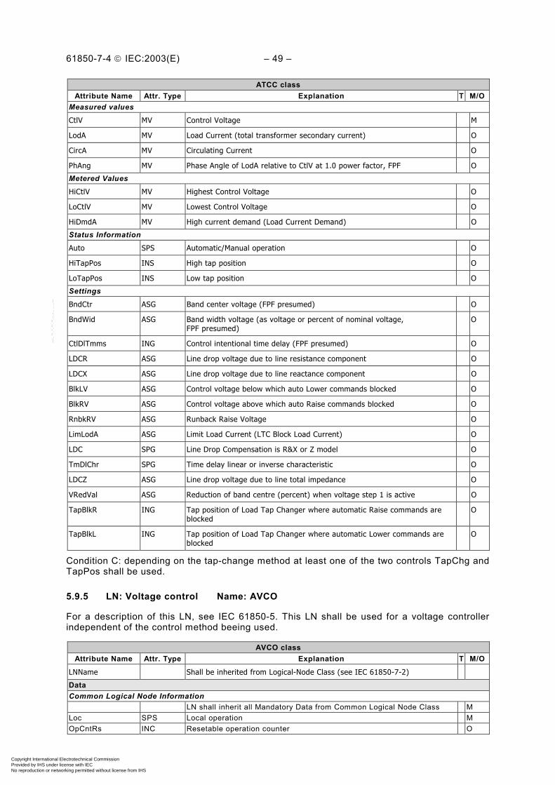
61850-7-4 IEC:2003(E) – 49 –
ATCC classAttribute Name Attr. Type Explanation T M/O
Measured values
CtlV MV Control Voltage M
LodA MV Load Current (total transformer secondary current) O
CircA MV Circulating Current O
PhAng MV Phase Angle of LodA relative to CtlV at 1.0 power factor, FPF O
Metered Values
HiCtlV MV Highest Control Voltage O
LoCtlV MV Lowest Control Voltage O
HiDmdA MV High current demand (Load Current Demand) O
Status Information
Auto SPS Automatic/Manual operation O
HiTapPos INS High tap position O
LoTapPos INS Low tap position O
Settings
BndCtr ASG Band center voltage (FPF presumed) O
BndWid ASG Band width voltage (as voltage or percent of nominal voltage,FPF presumed)
O
CtlDlTmms ING Control intentional time delay (FPF presumed) O
LDCR ASG Line drop voltage due to line resistance component O
LDCX ASG Line drop voltage due to line reactance component O
BlkLV ASG Control voltage below which auto Lower commands blocked O
BlkRV ASG Control voltage above which auto Raise commands blocked O
RnbkRV ASG Runback Raise Voltage O
LimLodA ASG Limit Load Current (LTC Block Load Current) O
LDC SPG Line Drop Compensation is R&X or Z model O
TmDlChr SPG Time delay linear or inverse characteristic O
LDCZ ASG Line drop voltage due to line total impedance O
VRedVal ASG Reduction of band centre (percent) when voltage step 1 is active O
TapBlkR ING Tap position of Load Tap Changer where automatic Raise commands areblocked
O
TapBlkL ING Tap position of Load Tap Changer where automatic Lower commands areblocked
O
Condition C: depending on the tap-change method at least one of the two controls TapChg andTapPos shall be used.
5.9.5 LN: Voltage control Name: AVCO
For a description of this LN, see IEC 61850-5. This LN shall be used for a voltage controllerindependent of the control method beeing used.
AVCO classAttribute Name Attr. Type Explanation T M/O
LNName Shall be inherited from Logical-Node Class (see IEC 61850-7-2)
DataCommon Logical Node Information
LN shall inherit all Mandatory Data from Common Logical Node Class MLoc SPS Local operation MOpCntRs INC Resetable operation counter O
Copyright International Electrotechnical Commission Provided by IHS under license with IEC
Not for ResaleNo reproduction or networking permitted without license from IHS
--``````-`-`,,`,,`,`,,`---
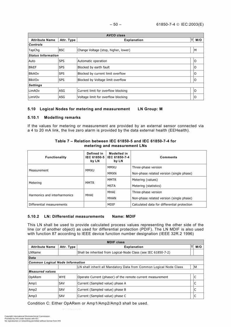
– 50 – 61850-7-4 IEC:2003(E)
AVCO classAttribute Name Attr. Type Explanation T M/O
Controls
TapChg BSC Change Voltage (stop, higher, lower) M
Status Information
Auto SPS Automatic operation O
BlkEF SPS Blocked by earth fault O
BlkAOv SPS Blocked by current limit overflow O
BlkVOv SPS Blocked by Voltage limit overflow O
Settings
LimAOv ASG Current limit for overflow blocking O
LimVOv ASG Voltage limit for overflow blocking O
5.10 Logical Nodes for metering and measurement LN Group: M
5.10.1 Modelling remarks
If the values for metering or measurement are provided by an external sensor connected viaa 4 to 20 mA link, the live zero alarm is provided by the data external health (EEHealth).
Table 7 – Relation between IEC 61850-5 and IEC 61850-7-4 formetering and measurement LNs
FunctionalityDefined in
IEC 61850-5by LN
Modelled inIEC 61850-7-4
by LNComments
Measurement MMXUMMXU
MMXN
Three-phase version
Non-phase related version (single phase)
Metering MMTRMMTR
MSTA
Metering (values)
Metering (statistics)
Harmonics and interharmonics MHAIMHAI
MHAN
Three-phase version
Non-phase related version (single phase)
Differential measurements MDIF Calculated data for differential protection
5.10.2 LN: Differential measurements Name: MDIF
This LN shall be used to provide calculated process values representing the other side of theline (or of another object) as used for differential protection (PDIF). The LN MDIF is also usedwith function 87 according to IEEE device function number designation (IEEE 32R.2 1996)
MDIF classAttribute Name Attr. Type Explanation T M/O
LNName Shall be inherited from Logical-Node Class (see IEC 61850-7-2)
DataCommon Logical Node Information
LN shall inherit all Mandatory Data from Common Logical Node Class MMeasured values
OpARem WYE Operate Current (phasor) of the remote current measurement C
Amp1 SAV Current (Sampled value) phase A C
Amp2 SAV Current (Sampled value) phase B C
Amp3 SAV Current (Sampled value) phase C C
Condition C: Either OpARem or Amp1/Amp2/Amp3 shall be used.
Copyright International Electrotechnical Commission Provided by IHS under license with IEC
Not for ResaleNo reproduction or networking permitted without license from IHS
--``````-`-`,,`,,`,`,,`---

61850-7-4 IEC:2003(E) – 51 –
5.10.3 LN: Harmonics or interharmonics Name: MHAI
For a description of this LN, see IEC 61850-5. This LN shall be used for calculation ofharmonics or interharmonics in a three-phase system. Instances either for harmonics (includingsubharmonics and multiples) or interharmonics are possible depending on the value of thebasic settings, i.e.:
• frequency f (“Hz”);
• evaluation window ∆t (“EvTmms”).
The frequency may either be given or calculated by means such as a phase-locked loop (onlypossible for a dominant frequency like the basic power frequency).
a) Settings for Harmonics, Subharmonics and multiplesEvTmms = 1/Hz (16 ms for 60 Hz, 20 ms for 50 Hz)NumCyc = 1 results in Harmonics only, i.e in multiples of Hz in a)NumCyc > 1 results in addition in Subharmonics and multiplesLowest frequency = 1/EvTmmsHighest frequency = (SmpRte)/2 (see TVTR, TCTR and IEC 61850-7-3)
b) Settings for InterharmonicsEvTmms = 1/Hz (adopted to the lowest interharmonics frequency expected)NumCyc = 1 results in Interharmonics, i.e. in multiples of Hz in b)NumCyc > 1 normally not used since the lowest frequency is freely adjusted by choice of HzLowest frequency = 1/EvTmmsHighest frequency = (SmpRte)/2 (see TVTR, TCTR and IEC 61850-7-3)
Both harmonics and interharmonics carry power and produce distortions. There are differentmethods to calculate disturbances. For more information and definitions see IEC 61000-4-7(1991), IEEE Std 519-1992, and IEEE Std 1459-2000.
MHAI classAttribute Name Attr. Type Explanation T M/O
LNName Shall be inherited from Logical-Node Class (see IEC 61850-7-2)
DataCommon Logical Node Information
LN shall inherit all Mandatory Data from Common Logical Node Class MEEHealth INS External equipment health (external sensor) OEEName DPL External equipment name plate OMeasured values
Hz MV Basic frequency C
HA HWYE Sequence of Harmonics or Interharmonics current O
HPhV HWYE Sequence of Harmonics or Interharominics phase to ground voltages O
HPPV HDEL Sequence of Harmonics or Interharmonics phase to phase voltages O
HW HWYE Sequence of Harmonics or Interharmonics active power O
HVAr HWYE Sequence of Harmonics or Interharmonics reactive power O
HVA HWYE Sequence of Harmonics or Interharmonics apparent power O
HRmsA WYE Current RMS Harmonic or Interharmonics (un-normalized Total harmonicdisortion, Thd)
O
HRmsPhV WYE Voltage RMS Harmonic or Interharmonics (un-normalized Thd) for phase toground
O
HRmsPPV DEL Voltage RMS Harmonic or Interharmonics (un-normalized Thd) for phase tophase
O
HTuW WYE Total phase Harmonic or Interharmonics active power (no fundamental)unsigned sum
O
HTsW WYE Total phase Harmonic or Interharmonic active power (no fundamental)signed sum
O
Copyright International Electrotechnical Commission Provided by IHS under license with IEC
Not for ResaleNo reproduction or networking permitted without license from IHS
--``````-`-`,,`,,`,`,,`---
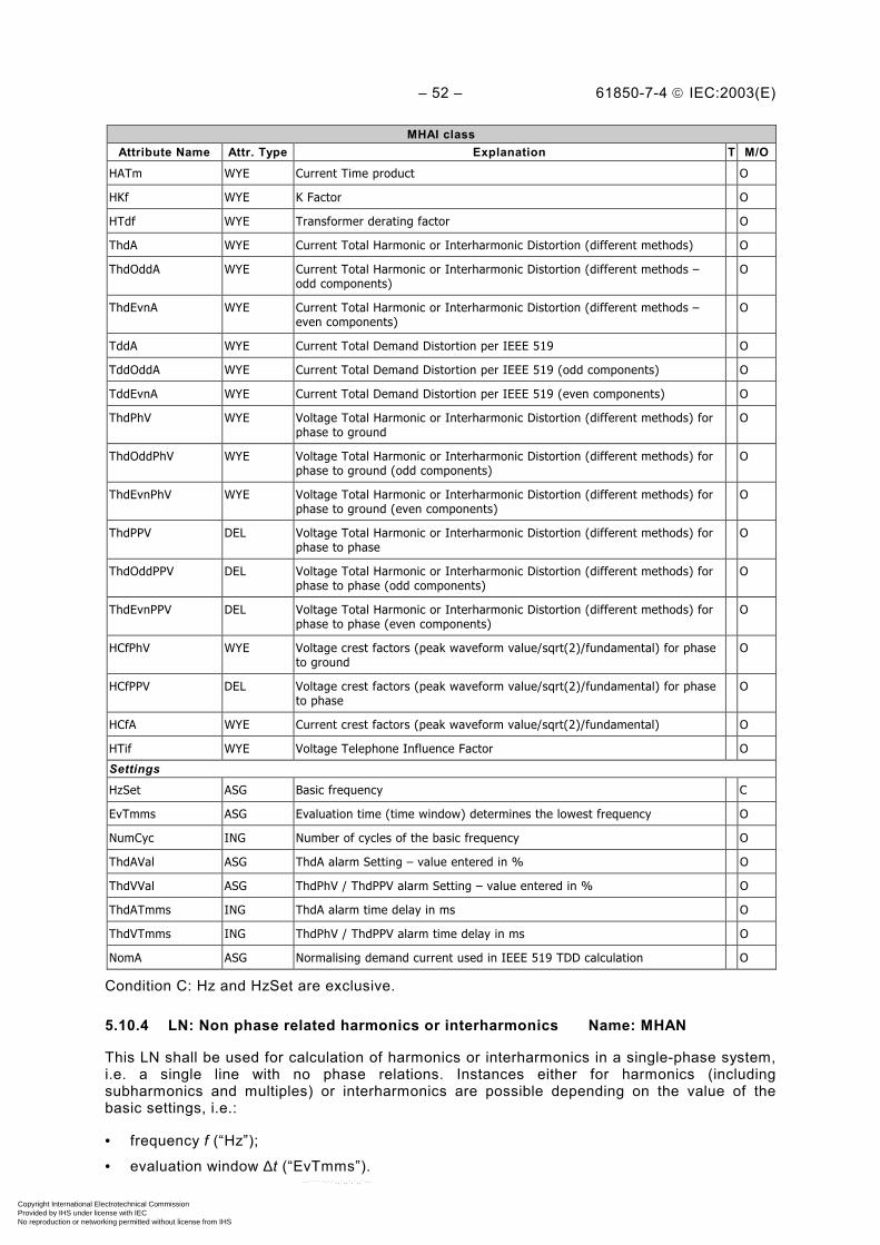
– 52 – 61850-7-4 IEC:2003(E)
MHAI classAttribute Name Attr. Type Explanation T M/O
HATm WYE Current Time product O
HKf WYE K Factor O
HTdf WYE Transformer derating factor O
ThdA WYE Current Total Harmonic or Interharmonic Distortion (different methods) O
ThdOddA WYE Current Total Harmonic or Interharmonic Distortion (different methods –odd components)
O
ThdEvnA WYE Current Total Harmonic or Interharmonic Distortion (different methods –even components)
O
TddA WYE Current Total Demand Distortion per IEEE 519 O
TddOddA WYE Current Total Demand Distortion per IEEE 519 (odd components) O
TddEvnA WYE Current Total Demand Distortion per IEEE 519 (even components) O
ThdPhV WYE Voltage Total Harmonic or Interharmonic Distortion (different methods) forphase to ground
O
ThdOddPhV WYE Voltage Total Harmonic or Interharmonic Distortion (different methods) forphase to ground (odd components)
O
ThdEvnPhV WYE Voltage Total Harmonic or Interharmonic Distortion (different methods) forphase to ground (even components)
O
ThdPPV DEL Voltage Total Harmonic or Interharmonic Distortion (different methods) forphase to phase
O
ThdOddPPV DEL Voltage Total Harmonic or Interharmonic Distortion (different methods) forphase to phase (odd components)
O
ThdEvnPPV DEL Voltage Total Harmonic or Interharmonic Distortion (different methods) forphase to phase (even components)
O
HCfPhV WYE Voltage crest factors (peak waveform value/sqrt(2)/fundamental) for phaseto ground
O
HCfPPV DEL Voltage crest factors (peak waveform value/sqrt(2)/fundamental) for phaseto phase
O
HCfA WYE Current crest factors (peak waveform value/sqrt(2)/fundamental) O
HTif WYE Voltage Telephone Influence Factor O
Settings
HzSet ASG Basic frequency C
EvTmms ASG Evaluation time (time window) determines the lowest frequency O
NumCyc ING Number of cycles of the basic frequency O
ThdAVal ASG ThdA alarm Setting – value entered in % O
ThdVVal ASG ThdPhV / ThdPPV alarm Setting – value entered in % O
ThdATmms ING ThdA alarm time delay in ms O
ThdVTmms ING ThdPhV / ThdPPV alarm time delay in ms O
NomA ASG Normalising demand current used in IEEE 519 TDD calculation O
Condition C: Hz and HzSet are exclusive.
5.10.4 LN: Non phase related harmonics or interharmonics Name: MHAN
This LN shall be used for calculation of harmonics or interharmonics in a single-phase system,i.e. a single line with no phase relations. Instances either for harmonics (includingsubharmonics and multiples) or interharmonics are possible depending on the value of thebasic settings, i.e.:
• frequency f (“Hz”);
• evaluation window ∆t (“EvTmms”).
Copyright International Electrotechnical Commission Provided by IHS under license with IEC
Not for ResaleNo reproduction or networking permitted without license from IHS
--``````-`-`,,`,,`,`,,`---
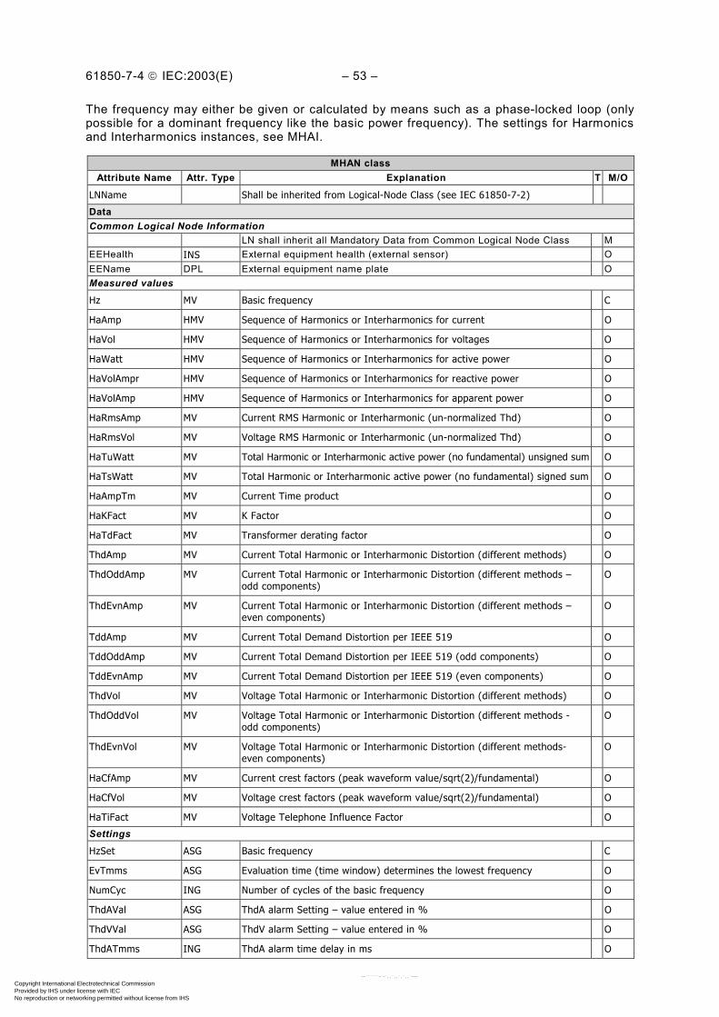
61850-7-4 IEC:2003(E) – 53 –
The frequency may either be given or calculated by means such as a phase-locked loop (onlypossible for a dominant frequency like the basic power frequency). The settings for Harmonicsand Interharmonics instances, see MHAI.
MHAN classAttribute Name Attr. Type Explanation T M/O
LNName Shall be inherited from Logical-Node Class (see IEC 61850-7-2)
DataCommon Logical Node Information
LN shall inherit all Mandatory Data from Common Logical Node Class MEEHealth INS External equipment health (external sensor) OEEName DPL External equipment name plate OMeasured values
Hz MV Basic frequency C
HaAmp HMV Sequence of Harmonics or Interharmonics for current O
HaVol HMV Sequence of Harmonics or Interharmonics for voltages O
HaWatt HMV Sequence of Harmonics or Interharmonics for active power O
HaVolAmpr HMV Sequence of Harmonics or Interharmonics for reactive power O
HaVolAmp HMV Sequence of Harmonics or Interharmonics for apparent power O
HaRmsAmp MV Current RMS Harmonic or Interharmonic (un-normalized Thd) O
HaRmsVol MV Voltage RMS Harmonic or Interharmonic (un-normalized Thd) O
HaTuWatt MV Total Harmonic or Interharmonic active power (no fundamental) unsigned sum O
HaTsWatt MV Total Harmonic or Interharmonic active power (no fundamental) signed sum O
HaAmpTm MV Current Time product O
HaKFact MV K Factor O
HaTdFact MV Transformer derating factor O
ThdAmp MV Current Total Harmonic or Interharmonic Distortion (different methods) O
ThdOddAmp MV Current Total Harmonic or Interharmonic Distortion (different methods –odd components)
O
ThdEvnAmp MV Current Total Harmonic or Interharmonic Distortion (different methods –even components)
O
TddAmp MV Current Total Demand Distortion per IEEE 519 O
TddOddAmp MV Current Total Demand Distortion per IEEE 519 (odd components) O
TddEvnAmp MV Current Total Demand Distortion per IEEE 519 (even components) O
ThdVol MV Voltage Total Harmonic or Interharmonic Distortion (different methods) O
ThdOddVol MV Voltage Total Harmonic or Interharmonic Distortion (different methods -odd components)
O
ThdEvnVol MV Voltage Total Harmonic or Interharmonic Distortion (different methods-even components)
O
HaCfAmp MV Current crest factors (peak waveform value/sqrt(2)/fundamental) O
HaCfVol MV Voltage crest factors (peak waveform value/sqrt(2)/fundamental) O
HaTiFact MV Voltage Telephone Influence Factor O
Settings
HzSet ASG Basic frequency C
EvTmms ASG Evaluation time (time window) determines the lowest frequency O
NumCyc ING Number of cycles of the basic frequency O
ThdAVal ASG ThdA alarm Setting – value entered in % O
ThdVVal ASG ThdV alarm Setting – value entered in % O
ThdATmms ING ThdA alarm time delay in ms O
Copyright International Electrotechnical Commission Provided by IHS under license with IEC
Not for ResaleNo reproduction or networking permitted without license from IHS
--``````-`-`,,`,,`,`,,`---
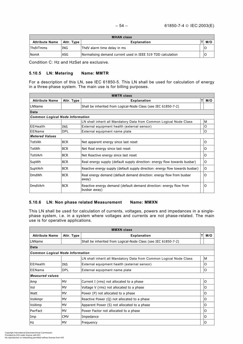
– 54 – 61850-7-4 IEC:2003(E)
MHAN classAttribute Name Attr. Type Explanation T M/O
ThdVTmms ING ThdV alarm time delay in ms O
NomA ASG Normalising demand current used in IEEE 519 TDD calculation O
Condition C: Hz and HzSet are exclusive.
5.10.5 LN: Metering Name: MMTR
For a description of this LN, see IEC 61850-5. This LN shall be used for calculation of energyin a three-phase system. The main use is for billing purposes.
MMTR classAttribute Name Attr. Type Explanation T M/O
LNName Shall be inherited from Logical-Node Class (see IEC 61850-7-2)
DataCommon Logical Node Information
LN shall inherit all Mandatory Data from Common Logical Node Class MEEHealth INS External equipment health (external sensor) OEEName DPL External equipment name plate OMetered Values
TotVAh BCR Net apparent energy since last reset O
TotWh BCR Net Real energy since last reset O
TotVArh BCR Net Reactive energy since last reset O
SupWh BCR Real energy supply (default supply direction: energy flow towards busbar) O
SupVArh BCR Reactive energy supply (default supply direction: energy flow towards busbar) O
DmdWh BCR Real energy demand (default demand direction: energy flow from busbaraway)
O
DmdVArh BCR Reactive energy demand (default demand direction: energy flow frombusbar away)
O
5.10.6 LN: Non phase related Measurement Name: MMXN
This LN shall be used for calculation of currents, voltages, powers and impedances in a single-phase system, i.e. in a system where voltages and currents are not phase-related. The mainuse is for operative applications.
MMXN classAttribute Name Attr. Type Explanation T M/O
LNName Shall be inherited from Logical-Node Class (see IEC 61850-7-2)
DataCommon Logical Node Information
LN shall inherit all Mandatory Data from Common Logical Node Class M
EEHealth INS External equipment health (external sensor) O
EEName DPL External equipment name plate O
Measured values
Amp MV Current I (rms) not allocated to a phase O
Vol MV Voltage V (rms) not allocated to a phase O
Watt MV Power (P) not allocated to a phase O
VolAmpr MV Reactive Power (Q) not allocated to a phase O
VolAmp MV Apparent Power (S) not allocated to a phase O
PwrFact MV Power Factor not allocated to a phase O
Imp CMV Impedance O
Hz MV Frequency O
Copyright International Electrotechnical Commission Provided by IHS under license with IEC
Not for ResaleNo reproduction or networking permitted without license from IHS
--``````-`-`,,`,,`,`,,`---
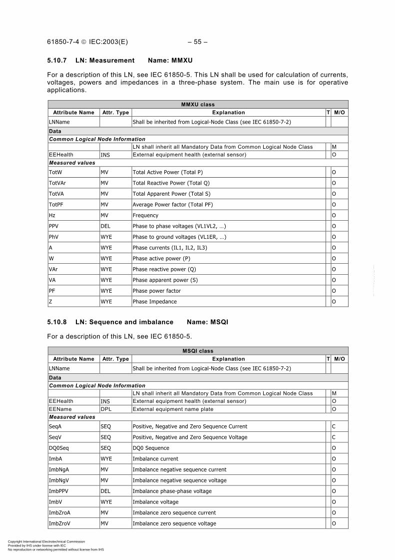
61850-7-4 IEC:2003(E) – 55 –
5.10.7 LN: Measurement Name: MMXU
For a description of this LN, see IEC 61850-5. This LN shall be used for calculation of currents,voltages, powers and impedances in a three-phase system. The main use is for operativeapplications.
MMXU classAttribute Name Attr. Type Explanation T M/O
LNName Shall be inherited from Logical-Node Class (see IEC 61850-7-2)
DataCommon Logical Node Information
LN shall inherit all Mandatory Data from Common Logical Node Class MEEHealth INS External equipment health (external sensor) OMeasured values
TotW MV Total Active Power (Total P) O
TotVAr MV Total Reactive Power (Total Q) O
TotVA MV Total Apparent Power (Total S) O
TotPF MV Average Power factor (Total PF) O
Hz MV Frequency O
PPV DEL Phase to phase voltages (VL1VL2, …) O
PhV WYE Phase to ground voltages (VL1ER, …) O
A WYE Phase currents (IL1, IL2, IL3) O
W WYE Phase active power (P) O
VAr WYE Phase reactive power (Q) O
VA WYE Phase apparent power (S) O
PF WYE Phase power factor O
Z WYE Phase Impedance O
5.10.8 LN: Sequence and imbalance Name: MSQI
For a description of this LN, see IEC 61850-5.
MSQI classAttribute Name Attr. Type Explanation T M/O
LNName Shall be inherited from Logical-Node Class (see IEC 61850-7-2)
DataCommon Logical Node Information
LN shall inherit all Mandatory Data from Common Logical Node Class MEEHealth INS External equipment health (external sensor) OEEName DPL External equipment name plate OMeasured values
SeqA SEQ Positive, Negative and Zero Sequence Current C
SeqV SEQ Positive, Negative and Zero Sequence Voltage C
DQ0Seq SEQ DQ0 Sequence O
ImbA WYE Imbalance current O
ImbNgA MV Imbalance negative sequence current O
ImbNgV MV Imbalance negative sequence voltage O
ImbPPV DEL Imbalance phase-phase voltage O
ImbV WYE Imbalance voltage O
ImbZroA MV Imbalance zero sequence current O
ImbZroV MV Imbalance zero sequence voltage O
Copyright International Electrotechnical Commission Provided by IHS under license with IEC
Not for ResaleNo reproduction or networking permitted without license from IHS
--``````-`-`,,`,,`,`,,`---

– 56 – 61850-7-4 IEC:2003(E)
MSQI classAttribute Name Attr. Type Explanation T M/O
MaxImbA MV Maximum imbalance current O
MaxImbPPV MV Maximum imbalance phase-phase voltage O
MaxImbV MV Maximum imbalance voltage O
Condition C: At least one of either data shall be used.
5.10.9 LN: Metering Statistics Name: MSTA
The metered values are not always used directly, but as average values, minima and maximaover a given evaluation period. The reporting may be started after the end of this period.
MSTA classAttribute Name Attr. Type Explanation T M/O
LNName Shall be inherited from Logical-Node Class (see IEC 61850-7-2)
DataCommon Logical Node Information
LN shall inherit all Mandatory Data from Common Logical Node Class MEEHealth INS External equipment health (external sensor) OEEName DPL External equipment name plate OMetered Values
AvAmps MV Average current O
MaxAmps MV Maximum current O
MinAmps MV Minimum current O
AvVolts MV Average voltage O
MaxVolts MV Maximum voltage O
MinVolts MV Minimum voltage O
AvVA MV Average apparent power O
MaxVA MV Maximum apparent power O
MinVA MV Minimum apparent power O
AvW MV Average real power O
MaxW MV Maximum real power O
MinW MV Minimum real power O
AvVAr MV Average reactive power O
MaxVAr MV Maximum reactive power O
MinVAr MV Minimum reactive power O
Controls
EvStr SPC Start of evaluation interval O
Settings
EvTmms ASG Evaluation time (time window) for averages, etc. O
Copyright International Electrotechnical Commission Provided by IHS under license with IEC
Not for ResaleNo reproduction or networking permitted without license from IHS
--``````-`-`,,`,,`,`,,`---

61850-7-4 IEC:2003(E) – 57 –
5.11 Logical Nodes for sensors and monitoring LN Group: S
5.11.1 Modelling remarks
Table 8 – Relation between IEC 61850-5 and IEC 61850-7-4for sensors and monitoring LNs
FunctionalityDefined in
IEC 61850-5by LN
Modelled inIEC 61850-7-4
by LNComments
Insulation medium supervision SIMSSIML
SIMG
Insulation liquid like oil
Insulation gas like SF6
5.11.2 LN: Monitoring and diagnostics for arcs Name: SARC
For a description of this LN, see IEC 61850-5.
SARC classAttribute Name Attr. Type Explanation T M/O
LNName Shall be inherited from Logical-Node Class (see IEC 61850-7-2)
DataCommon Logical Node Information
LN shall inherit all Mandatory Data from Common Logical Node Class MEEHealth INS External equipment health OEEName DPL External equipment name plate OOpCntRs INC Resetable Operation Counter (Switch and fault arcs) OStatus Information
FACntRs INC Fault arc counter M
FADet SPS Fault arc detected M
ArcCntRs INC Switch arc counter O
SwArcDet SPS Switch arc detected O
5.11.3 LN: Insulation medium supervision (gas) Name: SIMG
General description of this LN see IEC 61850-5. The insulation medium is a gas, for exampleSF6 in gas isolated devices. If more measurement positions are needed, these shall be addedby numbered extensions of the data (for Tmp use Tmp1, Tmp2, …).
SIMG classAttribute Name Attr. Type Explanation T M/O
LNName Shall be inherited from Logical-Node Class (see IEC 61850-7-2)
DataCommon Logical Node Information
LN shall inherit all Mandatory Data from Common Logical Node Class MEEHealth INS External equipment health OEEName DPL External equipment name plate OMeasured values
Pres MV Isolation gas pressure O
Den MV Isolation gas density O
Tmp MV Isolation gas temperature O
Status Information
InsAlm SPS Insulation gas critical (refill isolation medium) M
InsBlk SPS Insulation gas not safe (block device operation) O
InsTr SPS Insulation gas dangerous (trip for device isolation) O
PresAlm SPS Isolation gas pressure alarm C
Copyright International Electrotechnical Commission Provided by IHS under license with IEC
Not for ResaleNo reproduction or networking permitted without license from IHS
--``````-`-`,,`,,`,`,,`---

– 58 – 61850-7-4 IEC:2003(E)
SIMG classAttribute Name Attr. Type Explanation T M/O
DenAlm SPS Isolation gas density alarm C
TmpAlm SPS Isolation gas temperature alarm C
InsLevMax SPS Insulation gas level maximum (relates to predefined filling value) O
InsLevMin SPS Insulation gas level minimum (relates to predefined filling value) O
Condition C: depending on the supervised properties of the insulation gas, at least one statusinformation shall be used.
5.11.4 LN: Insulation medium supervision (liquid) Name: SIML
For a description of this LN, see IEC 61850-5. The insulation medium is a liquid such as oil likethat used for example for some transformers and tap changers. If more measurement positionsare needed, these shall be added by numbered extensions of the data (for Tmp use Tmp1,Tmp2, …).
SIML classAttribute Name Attr. Type Explanation T M/O
LNName Shall be inherited from Logical-Node Class (see IEC 61850-7-2)
DataCommon Logical Node Information
LN shall inherit all Mandatory Data from Common Logical Node Class MEEHealth INS External equipment health OEEName DPL External equipment name plate OMeasured values
Tmp MV Insulation liquid temperature O
Lev MV Insulation liquid level O
Pres MV Insulation liquid pressure O
H2O MV Relative saturation of moisture in insulating liquid (in %) OH2OTmp MV Temperature of insulating liquid at point of H2O measurement OH2 MV Measurement of Hydrogen (H2 in ppm) OStatus Information
InsAlm SPS Insulation liquid critical (refill isolation medium) M
InsBlk SPS Insulation liquid not safe (block device operation) O
InsTr SPS Insulation liquid dangerous (trip for device isolation) O
TmpAlm SPS Insulation liquid temperature alarm C
PresTr SPS Insulation liquid pressure trip C
PresAlm SPS Insulation liquid pressure alarm C
GasInsAlm SPS Gas in insulation liquid alarm (may be used for Buchholz alarm) O
GasInsTr SPS Gas in insulation liquid trip (may be used for Buchholz trip) O
GasFlwTr SPS Insulation liquid flow trip because of gas (may be used for Buchholz trip) O
InsLevMax SPS Insulation liquid level maximum O
InsLevMin SPS Insulation liquid level minimum O
H2Alm SPS H2 alarm O
MstAlm SPS Moisture sensor alarm O
Condition C: depending on the supervised properties of the liquid, at least one statusinformation shall be used.
Copyright International Electrotechnical Commission Provided by IHS under license with IEC
Not for ResaleNo reproduction or networking permitted without license from IHS
--``````-`-`,,`,,`,`,,`---

61850-7-4 IEC:2003(E) – 59 –
5.11.5 LN: Monitoring and diagnostics for partial discharges Name: SPDC
For a description of this LN, see IEC 61850-5.
SPDC classAttribute Name Attr. Type Explanation T M/O
LNName Shall be inherited from Logical-Node Class (see IEC 61850-7-2)
DataCommon Logical Node Information
LN shall inherit all Mandatory Data from Common Logical Node Class MEEHealth INS External equipment health OEEName DPL External equipment name plate OOpCnt INS Operation counter MMeasured values
AcuPaDsch MV Acoustic level of partial discharge in db C
Status information
PaDschAlm SPS Partial discharge alarm C
Condition C: depending on the functionality, at least one of the data AcuPaDsch or PaDschAlmshall be used.
5.12 Logical Nodes for switchgear LN Group: X
5.12.1 LN: Circuit breaker Name: XCBR
This LN is used for modelling switches with short circuit breaking capability. Additional LNs forexample SIMS, etc. may be required to complete the logical modelling for the breaker beingrepresented. The closing and opening commands shall be subscribed from CSWI or CPOW ifapplicable. If no services with real-time capability are available between CSWI or CPOWand XCBR, the opening and closing commands are performed with a GSE-message (seeIEC 61850-7-2).
XCBR classAttribute Name Attr. Type Explanation T M/O
LNName Shall be inherited from Logical-Node Class (see IEC 61850-7-2)
DataCommon Logical Node Information
LN shall inherit all Mandatory Data from Common Logical Node Class MLoc SPS Local operation (local means without substation automation
communication, hardwired direct control)M
EEHealth INS External equipment health OEEName DPL External equipment name plate OOpCnt INS Operation counter MControls
Pos DPC Switch position M
BlkOpn SPC Block opening M
BlkCls SPC Block closing M
ChaMotEna SPC Charger motor enabled O
Metered Values
SumSwARs BCR Sum of Switched Amperes, resetable O
Status Information
CBOpCap INS Circuit breaker operating capability M
POWCap INS Point On Wave switching capability O
MaxOpCap INS Circuit breaker operating capability when fully charged O
Copyright International Electrotechnical Commission Provided by IHS under license with IEC
Not for ResaleNo reproduction or networking permitted without license from IHS
--``````-`-`,,`,,`,`,,`---
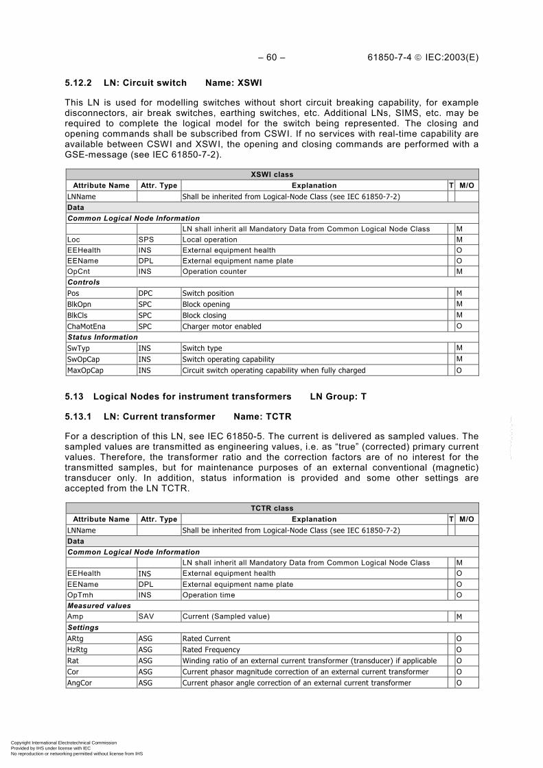
– 60 – 61850-7-4 IEC:2003(E)
5.12.2 LN: Circuit switch Name: XSWI
This LN is used for modelling switches without short circuit breaking capability, for exampledisconnectors, air break switches, earthing switches, etc. Additional LNs, SIMS, etc. may berequired to complete the logical model for the switch being represented. The closing andopening commands shall be subscribed from CSWI. If no services with real-time capability areavailable between CSWI and XSWI, the opening and closing commands are performed with aGSE-message (see IEC 61850-7-2).
XSWI classAttribute Name Attr. Type Explanation T M/O
LNName Shall be inherited from Logical-Node Class (see IEC 61850-7-2)DataCommon Logical Node Information
LN shall inherit all Mandatory Data from Common Logical Node Class MLoc SPS Local operation MEEHealth INS External equipment health OEEName DPL External equipment name plate OOpCnt INS Operation counter MControlsPos DPC Switch position MBlkOpn SPC Block opening MBlkCls SPC Block closing MChaMotEna SPC Charger motor enabled OStatus InformationSwTyp INS Switch type MSwOpCap INS Switch operating capability MMaxOpCap INS Circuit switch operating capability when fully charged O
5.13 Logical Nodes for instrument transformers LN Group: T
5.13.1 LN: Current transformer Name: TCTR
For a description of this LN, see IEC 61850-5. The current is delivered as sampled values. Thesampled values are transmitted as engineering values, i.e. as “true” (corrected) primary currentvalues. Therefore, the transformer ratio and the correction factors are of no interest for thetransmitted samples, but for maintenance purposes of an external conventional (magnetic)transducer only. In addition, status information is provided and some other settings areaccepted from the LN TCTR.
TCTR classAttribute Name Attr. Type Explanation T M/O
LNName Shall be inherited from Logical-Node Class (see IEC 61850-7-2)DataCommon Logical Node Information
LN shall inherit all Mandatory Data from Common Logical Node Class MEEHealth INS External equipment health OEEName DPL External equipment name plate OOpTmh INS Operation time OMeasured valuesAmp SAV Current (Sampled value) MSettingsARtg ASG Rated Current OHzRtg ASG Rated Frequency ORat ASG Winding ratio of an external current transformer (transducer) if applicable OCor ASG Current phasor magnitude correction of an external current transformer OAngCor ASG Current phasor angle correction of an external current transformer O
Copyright International Electrotechnical Commission Provided by IHS under license with IEC
Not for ResaleNo reproduction or networking permitted without license from IHS
--``````-`-`,,`,,`,`,,`---

61850-7-4 IEC:2003(E) – 61 –
5.13.2 LN: Voltage transformer Name: TVTR
For a description of this LN, see IEC 61850-5. The voltage is delivered as sampled values. Thesampled values are transmitted as engineering values, i.e. as “true” (corrected) primary voltagevalues. Therefore, the transformer ratio and the correction factors are of no interest for thetransmitted samples but for maintenance purposes of an external conventional (magnetic)transducer only. In addition, status information is provided and some other settings areaccepted from the LN TVTR.
TVTR classAttribute Name Attr. Type Explanation T M/O
LNName Shall be inherited from Logical-Node Class (see IEC 61850-7-2)
DataCommon Logical Node Information
LN shall inherit all Mandatory Data from Common Logical Node Class M
EEHealth INS External equipment health O
EEName DPL External equipment name plate O
OpTmh INS Operation time O
Measured valuesVol SAV Voltage (sampled value) M
Status InformationFuFail SPS TVTR fuse failure O
Settings
VRtg ASG Rated Voltage O
HzRtg ASG Rated frequency O
Rat ASG Winding ratio of external voltage transformer (transducer) if applicable O
Cor ASG Voltage phasor magnitude correction of external voltage transformer O
AngCor ASG Voltage phasor angle correction of external voltage transformer O
5.14 Logical Nodes for power transformers LN Group: Y
5.14.1 LN: Earth fault neutralizer (Petersen coil) Name: YEFN
For a description of this LN, see IEC 61850-5.
YEFN classAttribute Name Attr. Type Explanation T M/O
LNName Shall be inherited from Logical-Node Class (see IEC 61850-7-2)
DataCommon Logical Node Information
LN shall inherit all Mandatory Data from Common Logical Node Class MLoc SPS Local operation MEEHealth INS External equipment health OEEName DPL External equipment name plate OOpTmh INS Operation time OMeasured valuesECA MV Earth coil current MControls
ColTapPos ISC Coil Tap Position M
ColPos APC Plunge Core Position O
Copyright International Electrotechnical Commission Provided by IHS under license with IEC
Not for ResaleNo reproduction or networking permitted without license from IHS
--``````-`-`,,`,,`,`,,`---
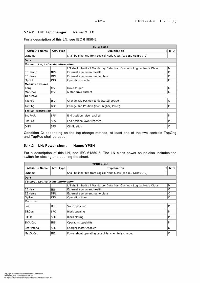
– 62 – 61850-7-4 IEC:2003(E)
5.14.2 LN: Tap changer Name: YLTC
For a description of this LN, see IEC 61850-5.
YLTC classAttribute Name Attr. Type Explanation T M/O
LNName Shall be inherited from Logical-Node Class (see IEC 61850-7-2)
DataCommon Logical Node Information
LN shall inherit all Mandatory Data from Common Logical Node Class MEEHealth INS External equipment health OEEName DPL External equipment name plate OOpCnt INS Operation counter OMeasured valuesTorq MV Drive torque OMotDrvA MV Motor drive current OControls
TapPos ISC Change Tap Position to dedicated position C
TapChg BSC Change Tap Position (stop, higher, lower) C
Status Information
EndPosR SPS End position raise reached M
EndPosL SPS End position lower reached M
OilFil SPS Oil filtration O
Condition C: depending on the tap-change method, at least one of the two controls TapChgand TapPos shall be used.
5.14.3 LN: Power shunt Name: YPSH
For a description of this LN, see IEC 61850-5. The LN class power shunt also includes theswitch for closing and opening the shunt.
YPSH classAttribute Name Attr. Type Explanation T M/O
LNName Shall be inherited from Logical-Node Class (see IEC 61850-7-2)
DataCommon Logical Node Information
LN shall inherit all Mandatory Data from Common Logical Node Class MEEHealth INS External equipment health OEEName DPL External equipment name plate OOpTmh INS Operation time OControls
Pos DPC Switch position M
BlkOpn SPC Block opening M
BlkCls SPC Block closing M
ShOpCap INS Operating capability M
ChaMotEna SPC Charger motor enabled O
MaxOpCap INS Power shunt operating capability when fully charged O
Copyright International Electrotechnical Commission Provided by IHS under license with IEC
Not for ResaleNo reproduction or networking permitted without license from IHS
--``````-`-`,,`,,`,`,,`---
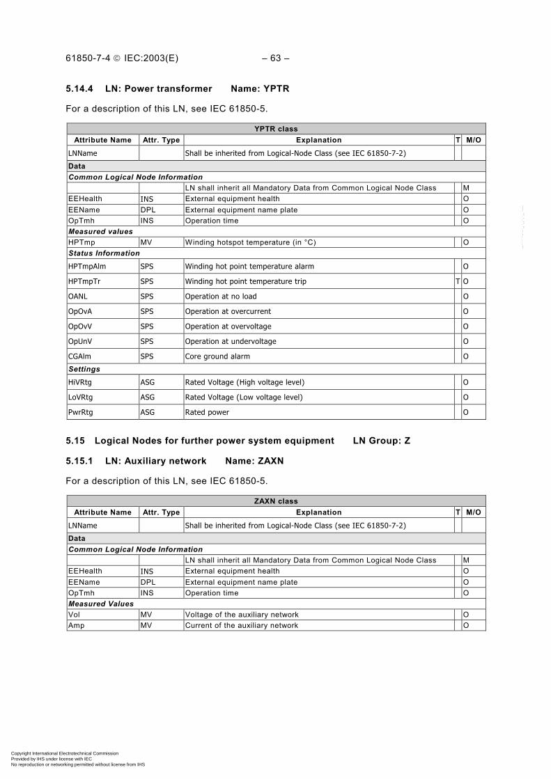
61850-7-4 IEC:2003(E) – 63 –
5.14.4 LN: Power transformer Name: YPTR
For a description of this LN, see IEC 61850-5.
YPTR classAttribute Name Attr. Type Explanation T M/O
LNName Shall be inherited from Logical-Node Class (see IEC 61850-7-2)
DataCommon Logical Node Information
LN shall inherit all Mandatory Data from Common Logical Node Class MEEHealth INS External equipment health OEEName DPL External equipment name plate OOpTmh INS Operation time OMeasured valuesHPTmp MV Winding hotspot temperature (in °C) OStatus Information
HPTmpAlm SPS Winding hot point temperature alarm O
HPTmpTr SPS Winding hot point temperature trip T O
OANL SPS Operation at no load O
OpOvA SPS Operation at overcurrent O
OpOvV SPS Operation at overvoltage O
OpUnV SPS Operation at undervoltage O
CGAlm SPS Core ground alarm O
Settings
HiVRtg ASG Rated Voltage (High voltage level) O
LoVRtg ASG Rated Voltage (Low voltage level) O
PwrRtg ASG Rated power O
5.15 Logical Nodes for further power system equipment LN Group: Z
5.15.1 LN: Auxiliary network Name: ZAXN
For a description of this LN, see IEC 61850-5.
ZAXN classAttribute Name Attr. Type Explanation T M/O
LNName Shall be inherited from Logical-Node Class (see IEC 61850-7-2)
DataCommon Logical Node Information
LN shall inherit all Mandatory Data from Common Logical Node Class MEEHealth INS External equipment health OEEName DPL External equipment name plate OOpTmh INS Operation time OMeasured ValuesVol MV Voltage of the auxiliary network OAmp MV Current of the auxiliary network O
Copyright International Electrotechnical Commission Provided by IHS under license with IEC
Not for ResaleNo reproduction or networking permitted without license from IHS
--``````-`-`,,`,,`,`,,`---

– 64 – 61850-7-4 IEC:2003(E)
5.15.2 LN: Battery Name: ZBAT
For a description of this LN, see IEC 61850-5.
ZBAT classAttribute Name Attr. Type Explanation T M/O
LNName Shall be inherited from Logical-Node Class (see IEC 61850-7-2)
DataCommon Logical Node Information
LN shall inherit all Mandatory Data from Common Logical Node Class MEEHealth INS External equipment health OEEName DPL External equipment name plate OOpTmh INS Operation time OMeasured ValuesVol MV Battery voltage MVolChgRte MV Rate of battery voltage change OAmp MV Battery drain current OControlsBatTest SPC Start battery test OStatus InformationTestRsl SPS Battery Test Results OBatHi SPS Battery high (voltage or charge - Overcharge) OBatLo SPS Battery low (voltage or charge) OSettings
LoBatVal ASG Low battery alarm value O
HiBatVal ASG High battery alarm value O
5.15.3 LN: Bushing Name: ZBSH
For a description of this LN, see IEC 61850-5.
ZBSH classAttribute Name Attr. Type Explanation T M/O
LNName Shall be inherited from Logical-Node Class (see IEC 61850-7-2)
DataCommon Logical Node Information
LN shall inherit all Mandatory Data from Common Logical Node Class MEEHealth INS External equipment health OEEName DPL External equipment name plate OOpTmh INS Operation time OMeasured valuesReact MV Relative capacitance of bushing MLosFact MV Loss Factor (tan delta) OVol MV Voltage of bushing OSettings
RefReact ASG Reference capacitance for bushing at commissioning O
RefPF ASG Reference power factor for bushing at commissioning O
RefV ASG Reference voltage for bushing at commissioning O
Copyright International Electrotechnical Commission Provided by IHS under license with IEC
Not for ResaleNo reproduction or networking permitted without license from IHS
--``````-`-`,,`,,`,`,,`---
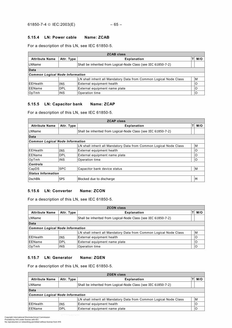
61850-7-4 IEC:2003(E) – 65 –
5.15.4 LN: Power cable Name: ZCAB
For a description of this LN, see IEC 61850-5.
ZCAB classAttribute Name Attr. Type Explanation T M/O
LNName Shall be inherited from Logical-Node Class (see IEC 61850-7-2)
DataCommon Logical Node Information
LN shall inherit all Mandatory Data from Common Logical Node Class MEEHealth INS External equipment health OEEName DPL External equipment name plate OOpTmh INS Operation time O
5.15.5 LN: Capacitor bank Name: ZCAP
For a description of this LN, see IEC 61850-5.
ZCAP classAttribute Name Attr. Type Explanation T M/O
LNName Shall be inherited from Logical-Node Class (see IEC 61850-7-2)
DataCommon Logical Node Information
LN shall inherit all Mandatory Data from Common Logical Node Class MEEHealth INS External equipment health OEEName DPL External equipment name plate OOpTmh INS Operation time OControlsCapDS SPC Capacitor bank device status MStatus Information
DschBlk SPS Blocked due to discharge M
5.15.6 LN: Converter Name: ZCON
For a description of this LN, see IEC 61850-5.
ZCON classAttribute Name Attr. Type Explanation T M/O
LNName Shall be inherited from Logical-Node Class (see IEC 61850-7-2)
DataCommon Logical Node Information
LN shall inherit all Mandatory Data from Common Logical Node Class MEEHealth INS External equipment health OEEName DPL External equipment name plate OOpTmh INS Operation time O
5.15.7 LN: Generator Name: ZGEN
For a description of this LN, see IEC 61850-5.
ZGEN classAttribute Name Attr. Type Explanation T M/O
LNName Shall be inherited from Logical-Node Class (see IEC 61850-7-2)
DataCommon Logical Node Information
LN shall inherit all Mandatory Data from Common Logical Node Class MEEHealth INS External equipment health OEEName DPL External equipment name plate O
Copyright International Electrotechnical Commission Provided by IHS under license with IEC
Not for ResaleNo reproduction or networking permitted without license from IHS
--``````-`-`,,`,,`,`,,`---

– 66 – 61850-7-4 IEC:2003(E)
ZGEN classAttribute Name Attr. Type Explanation T M/O
OpTmh INS Operation time OControlsGnCtl DPC Generator control MDExt SPC De-excitation MAuxSCO SPC Aux. supply change over OStopVlv SPC Stop valve OReactPwrR SPC Reactive power raise OReactPwrL SPC Reactive power lower OMeasured valuesGnSpd MV Speed OStatus Information
GnSt INS Generator state (stopped, Starting, Started, Stopping, Disabled) M
OANL SPS Operation at no load M
ClkRot SPS Phase rotation clockwise M
CntClkRot SPS Phase rotation counter clockwise M
OpUnExt SPS Operation at under-excitation M
OpOvExt SPS Operation at over-excitation M
LosOil SPS Loss of oil O
LosVac SPS Loss of vacuum O
PresAlm SPS Low pressure alarm O
Settings
DmdPwr ASG Demanded power O
PwrRtg ASG Rated power O
VRtg ASG Rated Voltage O
5.15.8 LN: Gas insulated line Name: ZGIL
For a description of this LN, see IEC 61850-5.
ZGIL classAttribute Name Attr. Type Explanation T M/O
LNName Shall be inherited from Logical-Node Class (see IEC 61850-7-2)
DataCommon Logical Node Information
LN shall inherit all Mandatory Data from Common Logical Node Class MEEHealth INS External equipment health OEEName DPL External equipment name plate OOpTmh INS Operation time O
5.15.9 LN: Power overhead line Name: ZLIN
For a description of this LN, see IEC 61850-5.
ZCAB classAttribute Name Attr. Type Explanation T M/O
LNName Shall be inherited from Logical-Node Class (see IEC 61850-7-2)
DataCommon Logical Node Information
LN shall inherit all Mandatory Data from Common Logical Node Class MEEHealth INS External equipment health OEEName DPL External equipment name plate OOpTmh INS Operation time O
Copyright International Electrotechnical Commission Provided by IHS under license with IEC
Not for ResaleNo reproduction or networking permitted without license from IHS
--``````-`-`,,`,,`,`,,`---
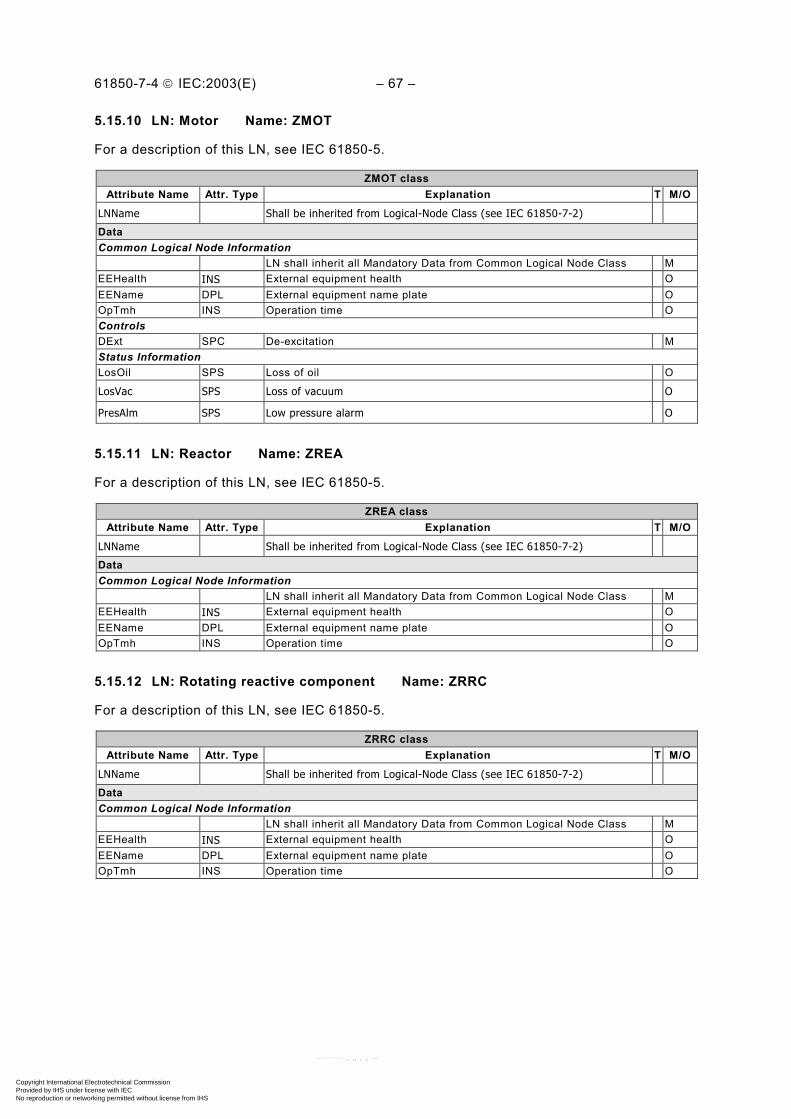
61850-7-4 IEC:2003(E) – 67 –
5.15.10 LN: Motor Name: ZMOT
For a description of this LN, see IEC 61850-5.
ZMOT classAttribute Name Attr. Type Explanation T M/O
LNName Shall be inherited from Logical-Node Class (see IEC 61850-7-2)
DataCommon Logical Node Information
LN shall inherit all Mandatory Data from Common Logical Node Class MEEHealth INS External equipment health OEEName DPL External equipment name plate OOpTmh INS Operation time OControlsDExt SPC De-excitation MStatus InformationLosOil SPS Loss of oil O
LosVac SPS Loss of vacuum O
PresAlm SPS Low pressure alarm O
5.15.11 LN: Reactor Name: ZREA
For a description of this LN, see IEC 61850-5.
ZREA classAttribute Name Attr. Type Explanation T M/O
LNName Shall be inherited from Logical-Node Class (see IEC 61850-7-2)
DataCommon Logical Node Information
LN shall inherit all Mandatory Data from Common Logical Node Class MEEHealth INS External equipment health OEEName DPL External equipment name plate OOpTmh INS Operation time O
5.15.12 LN: Rotating reactive component Name: ZRRC
For a description of this LN, see IEC 61850-5.
ZRRC classAttribute Name Attr. Type Explanation T M/O
LNName Shall be inherited from Logical-Node Class (see IEC 61850-7-2)
DataCommon Logical Node Information
LN shall inherit all Mandatory Data from Common Logical Node Class MEEHealth INS External equipment health OEEName DPL External equipment name plate OOpTmh INS Operation time O
Copyright International Electrotechnical Commission Provided by IHS under license with IEC
Not for ResaleNo reproduction or networking permitted without license from IHS
--``````-`-`,,`,,`,`,,`---

– 68 – 61850-7-4 IEC:2003(E)
5.15.13 LN: Surge arrestor Name: ZSAR
For a description of this LN, see IEC 61850-5.
ZSAR classAttribute Name Attr. Type Explanation T M/O
LNName Shall be inherited from Logical-Node Class (see IEC 61850-7-2)
DataCommon Logical Node Information
LN shall inherit all Mandatory Data from Common Logical Node Class MEEHealth INS External equipment health OEEName DPL External equipment name plate OOpCnt INS Operation counter OStatus Information
OPSA SPS Operation of surge arrestor T M
5.15.14 LN: Thyristor controlled frequency converter Name: ZTCF
For a description of this LN, see IEC 61850-5.
ZTCF classAttribute Name Attr. Type Explanation T M/O
LNName Shall be inherited from Logical-Node Class (see IEC 61850-7-2)
DataCommon Logical Node Information
LN shall inherit all Mandatory Data from Common Logical Node Class MEEHealth INS External equipment health OEEName DPL External equipment name plate OOpTmh INS Operation time OSettings
PwrFrq ASG Target frequency O
5.15.15 LN: Thyristor controlled reactive component Name: ZTCR
For a description of this LN, see IEC 61850-5.
ZTCR classAttribute Name Attr. Type Explanation T M/O
LNName Shall be inherited from Logical-Node Class (see IEC 61850-7-2)
DataCommon Logical Node Information
LN shall inherit all Mandatory Data from Common Logical Node Class MEEHealth INS External equipment health OEEName DPL External equipment name plate OOpTmh INS Operation time O
Copyright International Electrotechnical Commission Provided by IHS under license with IEC
Not for ResaleNo reproduction or networking permitted without license from IHS
--``````-`-`,,`,,`,`,,`---

61850-7-4 IEC:2003(E) – 69 –
6 Data name semantics
In Table 9, the data used in Clause 5 are described. The meaning of Boolean values areFALSE = 0, TRUE = 1.
Table 9 – Description of Data
Data Name Semantics
AcsCtlFail Number of access control failures detected.
AcuPaDsch Acoustic level of partial discharge in db.
AgeRat Ageing rate, for example of transformer.
Alm General single alarm.
AlmLstOv TRUE = Indication that the Alarm List has overflowed.
AlmThm Thermal Alarm.
AlmVal Alarm Value is the pre-set value for a measurand that when reached will result in an alarm.
Amp Current of a non-three-phase circuit.
Ang Angle between phase voltage and current.
AngCor Phase angle correction of a phasor (used for example for instrument transformers/transducers).
AngInd This Data indicates the check result of the differences between the angles of the busbar and linevoltages. FALSE indicates that the angle difference is below the required limit. The angle differencecriteria for the synchronising are fulfilled. TRUE indicates the angle difference exceeds the limit.The synchronising process shall be aborted because the angle criteria are not fulfilled(synchrocheck) or shall be continued with turbine control activities (synchronising).
AngLod Angle for load area. The following is an example of the definition of load encroachment used forthe Data AngLod and RisLod with polygonal characteristic, applicable also with MHO. PDIS1,PDIS2, and PDIS3 are different instances of the LN PDIS, one for each zone. See alsoRisGndRch.
jX
R
Forward
Forward
Reverse
Load encroachment
PDIS1
PDIS2
PDIS3
RisLodAngLod
Load encroachment
Reverse
IEC 1104/03
AnIn Analogue Input used for generic I/O.
ArcCntRs Arc counter, resetable.
Copyright International Electrotechnical Commission Provided by IHS under license with IEC
Not for ResaleNo reproduction or networking permitted without license from IHS
--``````-`-`,,`,,`,`,,`---

– 70 – 61850-7-4 IEC:2003(E)
Data Name Semantics
ARtg Rated current, intrinsic property of the device, which cannot be set/changed from remote.
AStr Current level: if this level is exceeded, the related functions start a dedicated action.
AuthFail Number of authorisation failures.
AutoThis Data is responsible for the enabling or disabling of the output circuit of the automaticcontroller; automatic (TRUE) = output circuit is enabled, not automatic (FALSE) = output circuit isdisabled.
AutoRecSt This Data represents whether or not the auto reclosing is ready, in progress, or successful.
Auto Reclosing Status ValueReady 1In Progress 2Successful 3
AutoUpLod TRUE = automatic uploading of the disturbance recorder files.
AuxSCO TRUE = Commands change over to operation from the auxiliary power supply.
AvAmps Average current in a defined evaluation interval (period)
AVCrv Characteristic Curve for protection operation of the form: y = f(x), where x = V (voltage) andy = A (current) The integers representing the different curves are given in the definition of CDCCURVE in IEC 61850-7-3.
AVSt Delivers the active curve characteristic.
AvVA Average apparent power in a defined evaluation interval (period).
AvVAr Average reactive power in a defined evaluation interval (period).
AvVolts Average voltage in a defined evaluation interval (period).
AvW Average real power in a defined evaluation interval (period).
BatHi TRUE = Indicates that battery is in overcharge condition.
BatLo TRUE = Indicates that battery voltage has dropped below a pre-set level.
BatTest TRUE = Command to start the battery test.
Copyright International Electrotechnical Commission Provided by IHS under license with IEC
Not for ResaleNo reproduction or networking permitted without license from IHS
--``````-`-`,,`,,`,`,,`---

61850-7-4 IEC:2003(E) – 71 –
Data Name Semantics
Beh
Since the logical device controls all logical nodes that are part of the logical device, the mode ofthe logical device (“LDMode” = LLN0.Mod) and the mode of a specific logical node (“LNMode” =XXXX.Mod) are related. The behaviour of a logical node is therefore a combination of LLN0.Modand XXXX.Mod and is described in the ”LNBeh” = XXXX.Beh. This Data is read-only and has thesame possible values as Mod (Mode). The value is determined according the following table:
LNMode LDMode LNBeh (read only) LNBehXXXX.Mod LLN0.Mod XXXX.Beh Valueon on on 1on blocked blocked 2on test test 3on test-blocked test-blocked 4on off off 5blocked on blocked 2blocked blocked blocked 2blocked test test-blocked 4blocked test-blocked test-blocked 4blocked off off 5test on test 3test blocked test-blocked 4test test test 3test test-blocked test-blocked 4test off off 5test-blocked on test-blocked 4test-blocked blocked test-blocked 4test-blocked test test-blocked 4test-blocked test-blocked test-blocked 4test-blocked off off 5off on off 5off blocked off 5off test off 5off test-blocked off 5off off off 5
BinIn Binary input array used for generic I/O, and represents a set of binary inputs.
BkrTmms Closing time of breaker including other delays until the operation of the breaker. This is a propertyof the breaker that is subject to ageing.
BlkA TRUE = Operation is blocked by current reasons.
BlkAOv TRUE = Switch operation is blocked by current limit overflow.
BlkCls
This Data is used to block 'close operation' (for example, for XCBR, XSWI, YPSH) from anotherlogical node such as a protection node or from a local/remote switch. An example may be the lowisolation gas density. Block closing is not reflected in operating capability. TRUE = block operation'close circuit breaker’.
BlkEF TRUE = Switch activity blocked due to earth fault.
BlkLV Control voltage below which auto Lower commands blocked.
BlkOpn
This Data is used to block 'open operation' (for example to XCBR, XSWI, YPSH) from anotherlogical node such as a protection node or from a local/remote switch. An example may be theblocking of the buscoupler also for trips during busbar transfer. Block opening is not reflected inoperating capability. TRUE = block operation 'open circuit breaker'.
BlkRec Block Reclosing.
BlkRV Control voltage above which auto Raise commands blocked.
BlkV TRUE = Operation is blocked for voltage reasons.
BlkVal When the measurements exceed (or drop below, in the case of a dropout function) this value, thefunction operation is blocked.
BlkValA Block Value (Minimum operating current).
BlkValV Block Value (Minimum operating voltage).
BlkVOv TRUE = Switch operation is blocked by voltage limit overflow.
Copyright International Electrotechnical Commission Provided by IHS under license with IEC
Not for ResaleNo reproduction or networking permitted without license from IHS
--``````-`-`,,`,,`,`,,`---

– 72 – 61850-7-4 IEC:2003(E)
Data Name Semantics
BlkZn This Data is used by the power swing protection to block operation of protection for a specificprotection zone i.e. the related instance of PDIS.
TRUE = blocked, FALSE = not blocked.
BndCtr Centre of control bandwidth, forward power flow presumed.
BndWid Band width, i.e. the defined range of control voltage given either as voltage value or percentage ofthe nominal voltage. Forward power flow is presumed if applicable.
CapDS TRUE = Capacitor bank is on line, or close. FALSE = Capacitor bank off line or open.
CarRx Carrier has been received after initiation of unblock logic.
CBOpCap This is an enumeration representing the physical capabilities of the breaker to operate. It reflectsthe switching energy as well as additional blocking due to some local problems.
CBOpCap is always less or equal to MaxOpCap.
Breaker Operating Capability ValueNone 1Open 2Close – Open 3Open – Close – Open 4Close – Open – Close – Open 5
More values (6...n) describe higher Operating Capabilities. A new value, i.e. a new line in the tablemust start alternating with "Close" and "Open" and must end always with “Open”.
CECtl Control of complete cooling group (pumps and fans).
CGAlm TRUE = Core Ground Alarm indicates that the insulation has broken down.
ChaMotEna This Data is used to enable the charger motor; used to prevent overload of the power supply aftera busbar trip. TRUE = enable charger motor, FALSE = disable charger motor.
ChkRec Determines if the reclosing is with (TRUE) or without (FALSE) synch-check.
ChNum Channel number being monitored (for example for COMTRADE).
ChrAng The angle by which the current is displaced from the polarising quantity in order to obtainmaximum sensitivity.
ChTrg Channel triggered. TRUE = channel started recording, FALSE = channnel not started recording.
CircA Measured circulating current, which circulates between transformers operated in parallel (onecomponent of transformer secondary current in a paralleling installation).
ClkRot TRUE = indication that phase rotation is clockwise (forward).
CntClkRot TRUE = indication that phase rotation is counter clockwise (reverse).
ColPos Represents the continuous adjustment of a coil (plunge core position) such as a Petersen Coil.
ColTapPos Represents the discrete adjustment of a coil such as a Petersen Coil.
ConsTms Time constant, for example for a thermal model.
Cor Magnitude correction of a phasor (used for example for instrument transformers/transducers).
CrdTmms Delay time in ms to wait on additional input if other actions are called for.
CtlDlTmms Control delay time before operating after reaching control point forward power flow presumed.
CtlV Voltage on secondary of transformer as used for voltage control.
DeaBusVal Voltage setting used to detect a Dead Bus bar, for example for auto reclosing.
DeaLinVal Voltage setting used to detect a Dead Line, for example for auto reclosing.
Den Density of insulating medium.
DenAlm Density alarm because of an abnormal condition (FALSE = Normal, TRUE = alert)
DetValA Used to detect that the breaker has opened when the current is below that setting.
DExt TRUE = Command to de-excite the machine.
Diag TRUE = Diagnostic is running, FALSE = Diagnostic is not running.
DifAClc Differential Current.
Copyright International Electrotechnical Commission Provided by IHS under license with IEC
Not for ResaleNo reproduction or networking permitted without license from IHS
--``````-`-`,,`,,`,`,,`---

61850-7-4 IEC:2003(E) – 73 –
Data Name Semantics
DifAng Setting for the phase angle difference between two measured values by a synch-check LN.
DifAngClc Calculated value for the phase angle difference between two measured values by a LN synch-check.
DifHz Setting for the frequency difference between two measured values by a synch-check LN.
DifHzClc Calculated value for the frequency difference between two measured values by a LN synch-check.
DifV Setting for the voltage difference between two measured values by a synch-check LN.
DifVClc Calculated value for the voltage difference between two measured values by a LN synch-check.
Dir The direction of a fault or power flow.
DirMod This Data is used to enable operation when the following directional conditions are met:
Direction Mode ValueNon Directional 1Forward 2Reverse 3
DltRcd TRUE = delete the selected record.
DmdPwr Demanded Power.
DmdVArh Reactive energy demand (default demand direction: energy flow from busbar away).
DmdWh Real energy demand (default demand direction: energy flow from busbar away).
DPCSO Generic double point control.
DQ0Seq Direct, quadrature, and zero axis quantity.
DschBlk TRUE = indicates that switch close action for capacitor bank is blocked due to the discharge stateof the bank.
DurTmms Minimum duration of carrier signal sent by a communication based scheme in ms.
ECA This is the measured current through a Petersen Coil in neutral compensated networks.
Echo Echo signal from weak end infeed function.
EEHealth This information reflects the state of external equipment, for example circuit breaker controlled bythe logical node XCBR. The values are the same as for the Health.
EEName This information reflects the name plate of external equipment, for example the circuit breakerXCBR controlled by the logical node CSWI.
EnaCls The interlocking function itself determines the status of this data and thus permits the closing ofthe device when TRUE. The control service checks this value before he controls “Close/On” aswitch.
EnaOpn The interlocking function itself determines the status of this data and thus permits the opening ofthe device when TRUE. The control service checks this value before he controls “Open/Off” aswitch.
EndPosL TRUE = Load tap changer is in the maximum lower position.
EndPosR TRUE = Load tap changer is in the maximum raise position.
EnvTmp Temperature of environment.
EqTmm Temperature Equalisation Time (min). For the duration of EqTmm, the thermal memory will bekept, i.e. the thermal memory is frozen. This time is active after the motor is switched off.
EvTmms Evaluation time in ms (time window) determines the lowest frequency.
ExclTmms Exclusion time in ms that consecutive triggers from the same source are ignored.
FACntRs Fault arc counter, resetable.
FADet TRUE = Alarm that fault arc has been detected.
Fail TRUE = indicates a breaker has failed to operate and a breaker failure has occurred.
Copyright International Electrotechnical Commission Provided by IHS under license with IEC
Not for ResaleNo reproduction or networking permitted without license from IHS
--``````-`-`,,`,,`,`,,`---
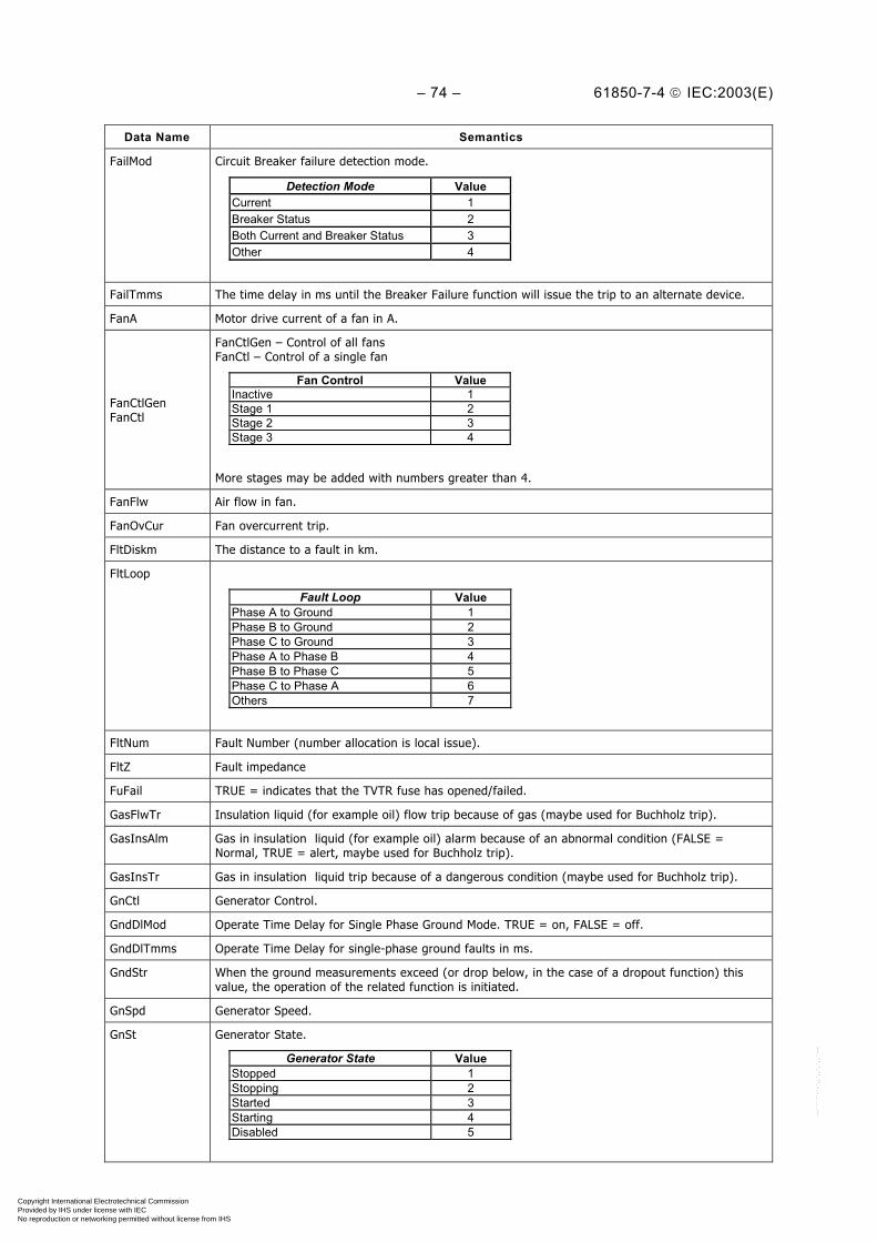
– 74 – 61850-7-4 IEC:2003(E)
Data Name Semantics
FailMod Circuit Breaker failure detection mode.
Detection Mode ValueCurrent 1Breaker Status 2Both Current and Breaker Status 3Other 4
FailTmms The time delay in ms until the Breaker Failure function will issue the trip to an alternate device.
FanA Motor drive current of a fan in A.
FanCtlGenFanCtl
FanCtlGen – Control of all fansFanCtl – Control of a single fan
Fan Control ValueInactive 1Stage 1 2Stage 2 3Stage 3 4
More stages may be added with numbers greater than 4.
FanFlw Air flow in fan.
FanOvCur Fan overcurrent trip.
FltDiskm The distance to a fault in km.
FltLoop
Fault Loop Value Phase A to Ground 1 Phase B to Ground 2 Phase C to Ground 3 Phase A to Phase B 4 Phase B to Phase C 5 Phase C to Phase A 6 Others 7
FltNum Fault Number (number allocation is local issue).
FltZ Fault impedance
FuFail TRUE = indicates that the TVTR fuse has opened/failed.
GasFlwTr Insulation liquid (for example oil) flow trip because of gas (maybe used for Buchholz trip).
GasInsAlm Gas in insulation liquid (for example oil) alarm because of an abnormal condition (FALSE =Normal, TRUE = alert, maybe used for Buchholz trip).
GasInsTr Gas in insulation liquid trip because of a dangerous condition (maybe used for Buchholz trip).
GnCtl Generator Control.
GndDlMod Operate Time Delay for Single Phase Ground Mode. TRUE = on, FALSE = off.
GndDlTmms Operate Time Delay for single-phase ground faults in ms.
GndStr When the ground measurements exceed (or drop below, in the case of a dropout function) thisvalue, the operation of the related function is initiated.
GnSpd Generator Speed.
GnSt Generator State.
Generator State Value Stopped 1 Stopping 2 Started 3 Starting 4 Disabled 5
Copyright International Electrotechnical Commission Provided by IHS under license with IEC
Not for ResaleNo reproduction or networking permitted without license from IHS
--``````-`-`,,`,,`,`,,`---

61850-7-4 IEC:2003(E) – 75 –
Data Name Semantics
GrAlm This Data summarises different alarms, assigned via configuration. TRUE = Indicates a GroupAlarm.
GrdRx If TRUE: receipt of a guard signal from the carrier set interface.
GriFltNum Grid Fault Number is used for identification of disturbance records of a common fault (numberallocation is local issue).
GrWrn This Data summarises different warnings, assigned via configuration TRUE = Indicates a GroupWarning.
H2 Measurement of Hydrogen (H2 in ppm). Combustible gas measurement in oil indicating the amountof deterioration of the insulation system.
H2Alm H2 alarm for gas composition (FALSE = Normal, TRUE = alert).
H2O Relative saturation of moisture in oil (in %). Note that this a measurement used in conjunctionwith H2OTmp.
H2OTmp Temperature of oil at point of measurement of relative saturation of moisture in oil (in °C). Notethat this is a measurement used in conjunction with H2O.
HA Phase related sequence of Harmonics or Interharmonics current for A, B C, N, Net, Res.
HaAmp Non phase related sequence of Harmonics or Interharmonics current.
HaAmpTm Non phase related Current Time product.
HaCfAmp Non phase related current crest factors (peak waveform value/sqrt(2)/fundamental).
HaCfVol Non phase related voltage crest factors (peak waveform value/sqrt(2)/fundamental).
HaKFact Non phase related K Factor.
HaRmsAmp Non phase related current RMS Harmonic or Interharmonic (un-normalized Thd).
HaRmsVol Non phase related voltage RMS Harmonic or Interharmonic (un-normalized Thd).
HaRst Number of the harmonic that is being monitored for restraint.
HaTdFact Non phase related Transformer derating factor.
HaTiFact Non phase related voltage Telephone Influence Factor, Method 1, 2, 3, …
HATm Phase related Current Time product.
HaTsWatt Non phase related total harmonic or interharmonic active power (no fundamental) signed sum.
HaTuWatt Non phase related total harmonic or interharmonic active power (no fundamental) unsigned sum.
HaVol Non phase related sequence of Harmonics or Interharmonics voltage.
HaVolAmp Non phase related sequence of Harmonics or Interharmonics apparent power.
HaVolAmpr Non phase related sequence of Harmonics or Interharmonics reactive power.
HaWatt Non phase related sequence of Harmonics or Interharmonics active power.
HCfA Phase related current crest factors (peak waveform value/sqrt(2)/fundamental).
HCfPhV Phase to ground voltage crest factors (peak waveform value/sqrt(2)/fundamental).
HCfPPV Phase to phase voltage crest factors (peak waveform value/sqrt(2)/fundamental).
Health
This information reflects the state of the logical node related HW and SW. More detailedinformation related to the source of the problem may be provided by specific Data. For LLN0, thisData reflects the worst value of “Health” of the logical nodes that are part of the logical deviceassociated with LLN0.
Health State ValueOk (“green”) – no problems, normal operation 1Warning (“yellow ”) – minor problems, but insafe operation mode
2
Alarm (“red”) – severe problem, no operationpossible
3
Health states 1 (“green”) and 3 (“red”) are unambiguous by definition. The detailed meaning ofHealth state 2 (“yellow”) is a local issue depending from the dedicated function/device.
HiBatVal High battery alarm value.
Copyright International Electrotechnical Commission Provided by IHS under license with IEC
Not for ResaleNo reproduction or networking permitted without license from IHS
--``````-`-`,,`,,`,`,,`---

– 76 – 61850-7-4 IEC:2003(E)
Data Name Semantics
HiCtlV Highest control voltage since last reset.
HiDmdA Highest current demand since last reset.
HiSet High operate value, percentage of the nominal current.
HiTapPos Highest tap position since last reset.
HiTrgLev High (positive) trigger level.
HiVRtg Rated Voltage (high voltage level).
HKf Phase related K Factor for A, B, C.
HPhV Sequence of Harmonics or Interharmonics for phase to ground voltages AN, BN, CN, NG.
HPPV Sequence of Harmonics or Interharmonics for phase to phase voltage AB, BC, CA.
HPTmp Winding hotspot temperature (in °C).
HPTmpAlm Hot Point Temperature alarm (FALSE = Normal, TRUE = High).
HPTmpTr TRUE = indicates that a trip has occurred due to winding hot point temperature.
HRmsA Phase related Current RMS Harmonic or Interharmonics (un-normalized Total harmonic disortion,Thd) for A, B, C, N.
HRmsPhV Phase to ground voltage RMS Harmonic or Interharmonic (un-normalized Thd) for AN, BN, CN, NG.
HRmsPPV Phase to phase voltage RMS Harmonic or Interharmonic (un-normalized Thd) for AB, BC, CA.
HTdf Phase related Transformer derating factor for A, B, C.
HTif Phase related voltage Telephone Influence Factor, Method 1, 2, 3, …
HTsW Phase related total phase harmonic or interharmonic active power (no fundamental) signed sum forA, B, C.
HTuW Phase related total phase harmonic or interharmonic active power (no fundamental) unsigned sumfor A, B, C.
HVA Phase related sequence of Harmonics or Interharmonics apparent power for A, B, C.
HVAr Phase related sequence of Harmonics or Interharmonics reactive power for A, B, C.
HVStr When the third harmonic phase voltage measurement exceeds this value, the PHIZ protectioncontrol operation is initiated.
HW Phase related sequence of Harmonics or Interharmonics active power for A, B, C.
Hz The frequency of a power system in Hz.
HzInd This Data indicates the check result of the differences between the frequencies of the busbar andline voltages. FALSE indicates that the frequency difference is below the required limit. Thefrequency difference criteria for the synchronising are fulfilled. TRUE indicates the frequencydifference exceeds the limit. The synchronising process shall be aborted because the frequencycriteria are not fulfilled (synchrocheck) or shall be continued with turbine control activities(synchronising).
HzRtg Rated frequency, intrinsic property of the device, which cannot be set/changed from remote.
HzSet Setting of a frequency.
IhA Phase related sequence of Interharmonics Current for A, B C, N, Net, Res.
IhAmp Non phase related sequence of Interharmonics Current.
IhPhV Sequence of Interharmonics for phase to ground voltages AN, BN, CN, NG.
IhPPV Sequence of Interharmonics for phase to phase voltage AB, BC, CA.
IhVA Phase related sequence of Interharmonics apparent power for A, B, C.
IhVAr Phase related sequence of Interharmonics reactive power for A, B, C.
IhVol Non phase related sequence of Interharmonics voltage.
IhVolAmp Non phase related sequence of Interharmonics apparent power.
IhVolAmpr Non phase related sequence of Interharmonics reactive power.
IhW Phase related sequence of Interharmonics active power for A, B, C.
IhWatt Non phase related sequence of Interharmonics active power.
Copyright International Electrotechnical Commission Provided by IHS under license with IEC
Not for ResaleNo reproduction or networking permitted without license from IHS
--``````-`-`,,`,,`,`,,`---

61850-7-4 IEC:2003(E) – 77 –
Data Name Semantics
ImbADeviation from the average phase current.ImbA.phsX = avex II − with Iave = (1/3) ×(IA + IB + IC)
ImbNgA Current Imbalance Negative Sequence Method. ImbNgA = I2 / I1
ImbNgV Voltage Imbalance Negative Sequence Method. ImbNgV = V2 / V1
ImbPPV Deviation from the average phase-to-phase voltage.ImbPPV.phsXY = VXY – PPVave with PPVave = (1/3) × (Vab + Vbc + Vca).
ImbV Deviation from the average phase-to-neutral voltage.ImbV.phsX = VX – Vave with Vave = (1/3) × (Van + Vbn + Vcn).
ImbZroA Current Imbalance Zero Sequence Method. ImbZroA = I0 / I1
ImbZroV Voltage Imbalance Zero Sequence Method. ImbZroV = V0 / V1
Ina Number of associations terminated due to inactivity.
Ind General indication.
InhTmm Time Setting for Restart Inhibition (min). Once the StrInh is activated, the motor should not beallowed to start until this time has elapsed.
InOvThis Data indicates that a buffer overflow occurred for the input buffer and importantannunciation’s may be lost (TRUE) for the communication. A general interrogation is recommendedor an integrity scan is started automatically.
InsAlm TRUE = provides an alarm after a pre-set limit is reached, for example low insulation level. Settingof the limits is a local issue and depends on the supervised media property. An appropriate actionmay be to refill the insulation medium.
InsBlk TRUE = block the operation of the isolated device when the level is reached where operation is notsafe anymore. Setting of the limits is a local issue and depends on the supervised media property.
InsLevMax TRUE = Insulation medium level has reached predetermined maximum level, mainly used for thefilling process.
InsLevMin TRUE = Insulation medium level has dropped to a predetermined minimum level, mainly used forthe filling process.
InsTrTRUE = the isolation of the device is not guaranteed anymore. The device has to switch off fromthe power system, i.e. it has to be isolated by tripping the surrounding breakers. Setting of thelimits is a local issue and depends on the supervised media property.
IntIn Integer status input used for generic I/O.
ISCSO Generic integer control output.
K0Fact K0 is Zero Sequence Compensation Factor = (Z0 – Z1)/3Z1 where Z0 is Zero SequenceImpedance, and Z1 is Positive Sequence Impedance.
K0FactAng Residual Compensation Factor Angle for K0.
LCol Lower Plunge Core Position.
LDC Line Drop Compensation. LDC is R&X or Z model TRUE = R&X, FALSE = Z.
LDCR Line drop voltage due to line resistance component (FPF presumed) at rated current.
LDCX Line drop voltage due to line reactance component (FPF presumed) at rated current.
LDCZ Line drop voltage due to line total impedance (FPF presumed) at rated current.
LEDRs Resets all light emitting diodes, true causes reset to occur.
Lev Level of insulating medium.
LevMod Internal Trigger Mode for disturbance recording.
Internal Trigger Mode ValuePositive or Rising 1Negative or Falling 2Both 3Other 4
LHz TRUE = Lower frequency, FALSE = no action.
LimAOv Current limit for overflow blocking.
Copyright International Electrotechnical Commission Provided by IHS under license with IEC
Not for ResaleNo reproduction or networking permitted without license from IHS
--``````-`-`,,`,,`,`,,`---

– 78 – 61850-7-4 IEC:2003(E)
Data Name Semantics
LimLodA The Data LodA current (percent) above which automatic commands suspended.
LimVOv Voltage limit for overflow blocking.
LinAng Line angle is the feeder/line impedance angle.
LinCapac Capacitance of the line.
LinLenKm The length of the line in km.
LivBusVal Voltage setting used to detect Live Bus, for example for auto reclosing.
LivDeaMod Live Dead Mode of operation under which switching may be carried out.
Live Dead Mode ValueDead Line, Dead Bus 1Live Line, Dead Bus 2Dead Line, Live Bus 3Dead Line, Dead Bus ORLive Line, Dead Bus
4
Dead Line, Dead Bus ORDead Line, Live Bus
5
Live Line, Dead Bus ORDead Line, Live Bus
6
Dead Line, Dead Bus ORLive Line, Dead Bus ORDead Line, Live Bus
7
LivLinVal Voltage setting used to detect Live Line, for example for auto reclosing.
LoBatVal Low battery alarm value.
Loc
This changeover is always done locally with a physical key or toggle switch. The physical key ortoggle switch may have a set of contacts from which the position can be read. This Data indicatesthe switchover between local and remote operation; local = TRUE, remote = FALSE. At bay level‘local’ means operation from the bay unit and ‘remote’ means opereation from a station unit. Atprocess level, ‘local’ means operation direct on the process device, for example on a circuit breakerand ‘remote’ means operation from a bay unit. If in a Logical Device the Loc of LLN0 is incontradiction to the Loc of any contained LN, “local” is always dominant.
LoCtlV Lowest Control Voltage since last reset.
LodA Load side current of transformer.
LodRsvAlm Load reserve to alarm.
LodRsvTr Load reserve to trip.
LokRotTms Locked Rotor Time (s). This time is the permissible locked rotor time during start-up.
LoSet Low operate value, percentage of the nominal current.
LosFact Loss Factor (tan delta)
LosOfGrd Loss of guard.
LosOil TRUE = indicates that a loss of oil has been detected.
LosVac TRUE = indicates when vacuum drops below a predetermined level.
LoTapPos Lowest tap position since last reset.
LoTrgLev Low (negative) trigger level.
LoVRtg Rated Voltage (low voltage level).
LTCBlk TRUE = Automatic control of LTC blocked (inhibited).
LTCDragRs TRUE = Reset LTC Drag Hands (high and low positions to present position).
LV TRUE = Lower voltage, FALSE = no action.
MaxAmps Maximum current in a defined evaluation interval (period).
MaxDlTmms Operation instant difference (between intended and performed operation).
MaxEna Monitoring of current exceeding a set value is enabled (TRUE) in order to detect a fault conditionduring power swing in the system.
MaxFwdAng Maximum phase angle in forward direction.
Copyright International Electrotechnical Commission Provided by IHS under license with IEC
Not for ResaleNo reproduction or networking permitted without license from IHS
--``````-`-`,,`,,`,`,,`---

61850-7-4 IEC:2003(E) – 79 –
Data Name Semantics
MaxImbA Maximum deviation from the average current.Max(Idev_a,Idev_b,Idev_c)
MaxImbPPV Maximum deviation from the average phase-to-phase voltage.MaxImbPPV = Max(PPVdev_a,PPVdev_b,PPVdev_c)
MaxImbV Maximum deviation from the average phase-to-neutral voltage.MaxImbV = Max(Vdev_a,Vdev_b,Vdev_c)
MaxNumRcd Maximum number of records that can be recorded.
MaxNumStr
Setting for the maximum number of starts. This Data is also used for the permissible number ofcold starts. For example, the motor manufacturer may state that three starts at the maximum areallowed within 1 h. These parameters are intended for this. So MaxNumStr is set to 3 andMaxStrTmm is set to 60 (min).
MaxOpCapThis Data shall provide the information of the operation capability available when the switchmechanism is fully charged. The Maximum Operating Capability gives the information about themaximum of CBOpCap.
MaxOpTmms The Data maximum operating time in ms for the LN is used for co-ordinating action of the relatedfunction.
MaxRvAng Maximum phase angle in reverse direction.
MaxStrTmm The time period in which the maximum number of starts is allowed.
MaxVA Maximum apparent power in a defined evaluation interval (period).
MaxVAr Maximum reactive power in a defined evaluation interval (period).
MaxVolts Maximum voltage in a defined evaluation interval (period).
MaxW Maximum real power in a defined evaluation interval (period).
MaxWrmStr Permissible number of warm starts, in most cases cold starts – 1.
MemClr TRUE = Clear Memory.
MemFull This Data is the percentage at which to indicate memory is full.
MemOv TRUE = Memory overflow has occurred.
MemRs TRUE = resetting the memory in the recorder.
MemUsed Percentage of storage memory in use.
MinAmps Minimum current in a defined evaluation interval (period).
MinFwdAng Minimum phase angle in forward direction.
MinOpTmms The Data minimum operating time in ms for the LN is used for co-ordinating with olderelectromechanical relays.
MinPPV Minimum phase to phase Voltage.
MinRvAng Minimum phase angle in reverse direction.
MinVA Minimum apparent power in a defined evaluation interval (period).
MinVAr Minimum reactive power in a defined evaluation interval (period).
MinVolts Minimum voltage in a defined evaluation interval (period).
MinW Minimum real power in a defined evaluation interval (period).
Copyright International Electrotechnical Commission Provided by IHS under license with IEC
Not for ResaleNo reproduction or networking permitted without license from IHS
--``````-`-`,,`,,`,`,,`---
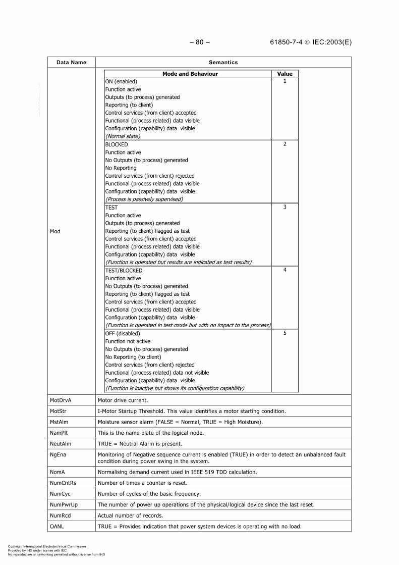
– 80 – 61850-7-4 IEC:2003(E)
Data Name Semantics
Mod
Mode and Behaviour ValueON (enabled)Function activeOutputs (to process) generatedReporting (to client)Control services (from client) acceptedFunctional (process related) data visibleConfiguration (capability) data visible(Normal state)
1
BLOCKEDFunction activeNo Outputs (to process) generatedNo ReportingControl services (from client) rejectedFunctional (process related) data visibleConfiguration (capability) data visible(Process is passively supervised)
2
TESTFunction activeOutputs (to process) generatedReporting (to client) flagged as testControl services (from client) acceptedFunctional (process related) data visibleConfiguration (capability) data visible(Function is operated but results are indicated as test results)
3
TEST/BLOCKEDFunction activeNo Outputs (to process) generatedReporting (to client) flagged as testControl services (from client) acceptedFunctional (process related) data visibleConfiguration (capability) data visible(Function is operated in test mode but with no impact to the process)
4
OFF (disabled)Function not activeNo Outputs (to process) generatedNo Reporting (to client)Control services (from client) rejectedFunctional (process related) data not visibleConfiguration (capability) data visible(Function is inactive but shows its configuration capability)
5
MotDrvA Motor drive current.
MotStr I-Motor Startup Threshold. This value identifies a motor starting condition.
MstAlm Moisture sensor alarm (FALSE = Normal, TRUE = High Moisture).
NamPlt This is the name plate of the logical node.
NeutAlm TRUE = Neutral Alarm is present.
NgEna Monitoring of Negative sequence current is enabled (TRUE) in order to detect an unbalanced faultcondition during power swing in the system.
NomA Normalising demand current used in IEEE 519 TDD calculation.
NumCntRs Number of times a counter is reset.
NumCyc Number of cycles of the basic frequency.
NumPwrUp The number of power up operations of the physical/logical device since the last reset.
NumRcd Actual number of records.
OANL TRUE = Provides indication that power system devices is operating with no load.
Copyright International Electrotechnical Commission Provided by IHS under license with IEC
Not for ResaleNo reproduction or networking permitted without license from IHS
--``````-`-`,,`,,`,`,,`---

61850-7-4 IEC:2003(E) – 81 –
Data Name Semantics
Ofs Offset, for Analogue Values, the offset from zero of the Analogue Value.
OilFil TRUE = Oil filtration is operational/running.
OilMotA Oil circulation motor drive current.
OilTmpIn Oil temperature cooler in.
OilTmpOut Oil temperature cooler out.
OilTmpSet Set point for oil temperature.
Op Operate (Common Data Classes ACT) indicates the trip decision of a protection function (LN). Thetrip itself is issued by PTRC.
OpARem The remote operating current (phasor) used by the differential protection function.
OpCls Operation Close Switch. OpCls shall be used if the control model of IEC 61850-7-2 is not supportedbetween CSWI or CPOW and XCBR or XSWI. Note that the state must last long enough so that theclient can detect it.
OpCntThis Data represents a count of operations that is not resetable. In general, this type of counter isincluded in the following LNs: XCBR, XSWI, and YLTC. The counter shall not be reset from remotebut maybe from local.
OpCntRs This Data represents a resetable LN operations counter. The use of the INC Common Data Class,permits setting the counter to something other than “0”.
OpDlTmms Time delay in ms before operating once operate conditions have been met.
OpEx Trip of a breaker failure function to a circuit breaker other than the faulty one to switch off thegrid fault ("external trip").
OpIn Retrip of a breaker failure function after a trip of a protection function was not successful("internal trip").
OpOpn Operation Open Switch. OpOpn shall be used if the control model of IEC 61850-7-2 is notsupported between CSWI or CPOW and XCBR or XSWI. Note that the state must last long enoughso that the client can detect it.
OpOvA TRUE = Device is operating under an overcurrent condition.
OpOvExt TRUE = Device operating in an over excited condition.
OpOvV TRUE = Device is operating under an overvoltage condition.
OPSA TRUE = Surge arrestor operation detected.
OpTmh This Data indicates the Operation time in h of a physical device since start of the operation. Detailsare LN specific.
OpUnExt TRUE = Device operated in an under-excited condition.
OpUnV TRUE = Device operating in an under voltage condition.
OutOvThis Data indicates that a buffer overflow occurred for the output buffer and importantannunciation’s may be lost (TRUE) for the communication. A general interrogation is recommendedor an integrity scan is started automatically.
PaDschAlm TRUE = Partial Discharge has reached pre-set alarm level.
ParOp Transformers are operating in parallel.
Copyright International Electrotechnical Commission Provided by IHS under license with IEC
Not for ResaleNo reproduction or networking permitted without license from IHS
--``````-`-`,,`,,`,`,,`---

– 82 – 61850-7-4 IEC:2003(E)
Data Name Semantics
PctOfs Distance characteristic offset in percent of the line length.
xPctOfs
Slp(+)
PctRch
REACH
Y
IEC 1105/03
PctRch Distance characteristic reach in percent of the line length; see curve in PctOfs.
PerTrgTms Periodic trigger time in s.
PF Phase to ground power factor for Phases 1, 2, and 3, including Angle.
PhA Phase current in amperes for Phases 1, 2, and 3, including Angle.
PhAng Phase angle of LodA relative to CtlV at 1.0 power factor, assuming forward power flow.
PhDlMod Operate Time Delay Multiphase Mode. TRUE = on, FALSE = off
PhDlTmms Operate Time Delay for Multiphase Faults in ms.
PhGndVal Phase to ground is the Undervoltage level for WEI (weak end infeed) condition for a phase toground measurement.
PhStop Phase Stop Value.
PhStr When the phase measurements exceed (or drop below, in the case of a dropout function) thisvalue, the operation of the related function is initiated.
PhV Phase to ground voltages for Phases 1, 2, and 3, including Angle.
PhVA Phase to ground apparent power for Phases 1, 2, and 3, including Angle.
PhVAr Phase to ground reactive for Phases 1, 2, and 3, including Angle.
PhW Phase to ground active power for Phases 1, 2, and 3, including Angle.
PhyHealth See Health in Common Logical Node Information.
PhyNam This is the name plate of the physical device.
PhZ Phase Impedance.
PlsTmms Defines the length of the breaker closing pulse from the reclosing LN.
PmpAlm Loss of pump is indicated.
PmpCtlGenPmpCtl
PmpCtlGen – Control of all pumps.PmpCtl – Control of a single pump.
Pump Control ValueInactive 1Stage 1 2Stage 2 3Stage 3 4
More stages may be added with numbers greater than 4
PmpOvCur Pump overcurrent trip.
Copyright International Electrotechnical Commission Provided by IHS under license with IEC
Not for ResaleNo reproduction or networking permitted without license from IHS
--``````-`-`,,`,,`,`,,`---
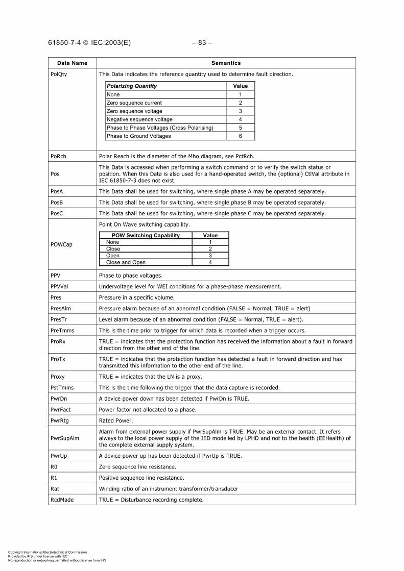
61850-7-4 IEC:2003(E) – 83 –
Data Name Semantics
PolQty This Data indicates the reference quantity used to determine fault direction.
Polarizing Quantity Value None 1 Zero sequence current 2 Zero sequence voltage 3 Negative sequence voltage 4 Phase to Phase Voltages (Cross Polarising) 5 Phase to Ground Voltages 6
PoRch Polar Reach is the diameter of the Mho diagram, see PctRch.
PosThis Data is accessed when performing a switch command or to verify the switch status orposition. When this Data is also used for a hand-operated switch, the (optional) CtlVal attribute inIEC 61850-7-3 does not exist.
PosA This Data shall be used for switching, where single phase A may be operated separately.
PosB This Data shall be used for switching, where single phase B may be operated separately.
PosC This Data shall be used for switching, where single phase C may be operated separately.
POWCap
Point On Wave switching capability.
POW Switching Capability ValueNone 1Close 2Open 3Close and Open 4
PPV Phase to phase voltages.
PPVVal Undervoltage level for WEI conditions for a phase-phase measurement.
Pres Pressure in a specific volume.
PresAlm Pressure alarm because of an abnormal condition (FALSE = Normal, TRUE = alert)
PresTr Level alarm because of an abnormal condition (FALSE = Normal, TRUE = alert).
PreTmms This is the time prior to trigger for which data is recorded when a trigger occurs.
ProRx TRUE = indicates that the protection function has received the information about a fault in forwarddirection from the other end of the line.
ProTx TRUE = indicates that the protection function has detected a fault in forward direction and hastransmitted this information to the other end of the line.
Proxy TRUE = indicates that the LN is a proxy.
PstTmms This is the time following the trigger that the data capture is recorded.
PwrDn A device power down has been detected if PwrDn is TRUE.
PwrFact Power factor not allocated to a phase.
PwrRtg Rated Power.
PwrSupAlmAlarm from external power supply if PwrSupAlm is TRUE. May be an external contact. It refersalways to the local power supply of the IED modelled by LPHD and not to the health (EEHealth) ofthe complete external supply system.
PwrUp A device power up has been detected if PwrUp is TRUE.
R0 Zero sequence line resistance.
R1 Positive sequence line resistance.
Rat Winding ratio of an instrument transformer/transducer
RcdMade TRUE = Disturbance recording complete.
Copyright International Electrotechnical Commission Provided by IHS under license with IEC
Not for ResaleNo reproduction or networking permitted without license from IHS
--``````-`-`,,`,,`,`,,`---
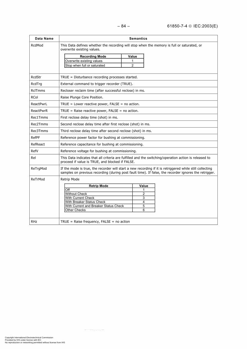
– 84 – 61850-7-4 IEC:2003(E)
Data Name Semantics
RcdMod This Data defines whether the recording will stop when the memory is full or saturated, oroverwrite existing values.
Recording Mode ValueOverwrite existing values 1Stop when full or saturated 2
RcdStr TRUE = Disturbance recording processes started.
RcdTrg External command to trigger recorder (TRUE).
RclTmms Recloser reclaim time (after successful reclose) in ms.
RCol Raise Plunge Core Position.
ReactPwrL TRUE = Lower reactive power, FALSE = no action.
ReactPwrR TRUE = Raise reactive power, FALSE = no action.
Rec1Tmms First reclose delay time (shot) in ms.
Rec2Tmms Second reclose delay time after first reclose (shot) in ms.
Rec3Tmms Third reclose delay time after second reclose (shot) in ms.
RefPF Reference power factor for bushing at commissioning.
RefReact Reference capacitance for bushing at commissioning.
RefV Reference voltage for bushing at commissioning.
Rel This Data indicates that all criteria are fulfilled and the switching/operation action is released toproceed if value is TRUE, and blocked if FALSE.
ReTrgMod If the mode is true, the recorder will start a new recording if it is retriggered while still collectingsamples on previous recording (during post fault time). If false, the recorder ignores the retrigger.
ReTrMod Retrip Mode
Retrip Mode ValueOff 1Without Check 2With Current Check 3With Breaker Status Check 4With Current and Breaker Status Check 5Other Checks 6
RHz TRUE = Raise frequency, FALSE = no action
Copyright International Electrotechnical Commission Provided by IHS under license with IEC
Not for ResaleNo reproduction or networking permitted without license from IHS
--``````-`-`,,`,,`,`,,`---
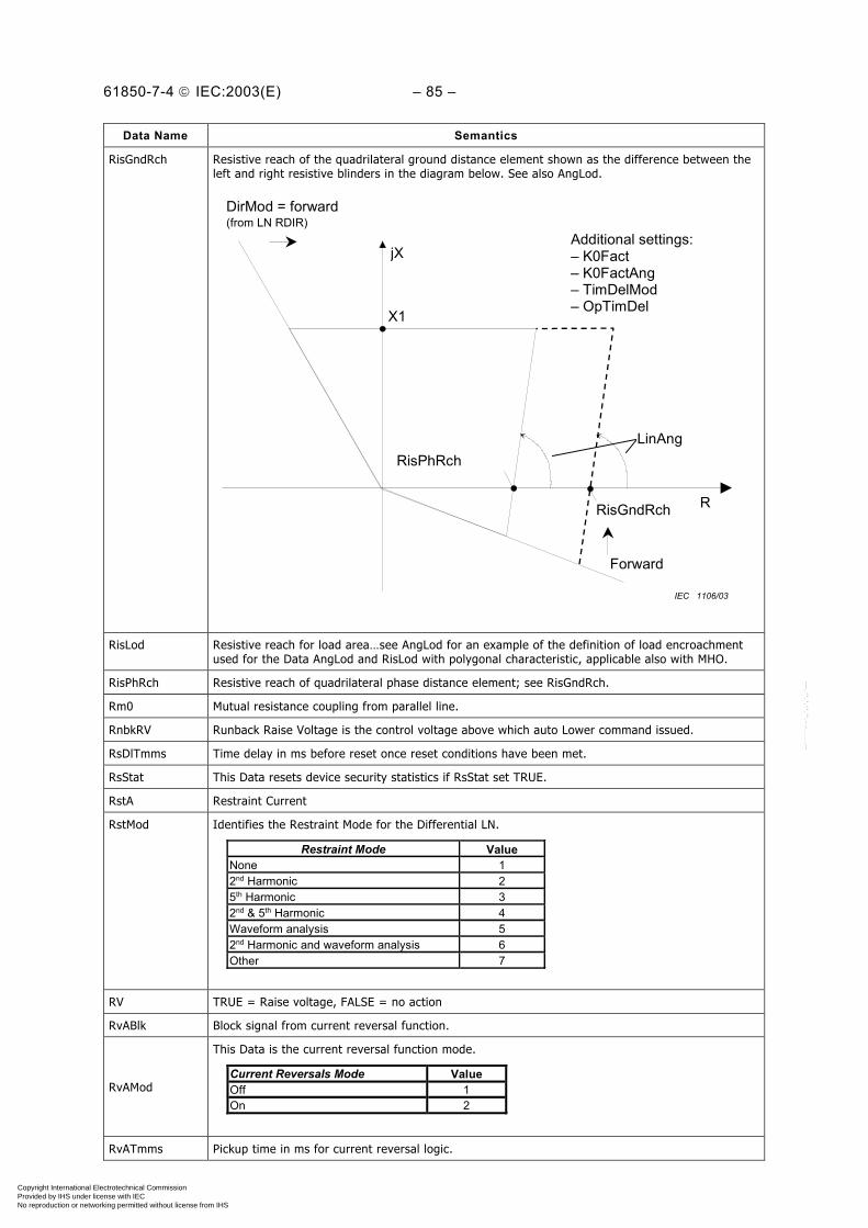
61850-7-4 IEC:2003(E) – 85 –
Data Name Semantics
RisGndRch Resistive reach of the quadrilateral ground distance element shown as the difference between theleft and right resistive blinders in the diagram below. See also AngLod.
jX
R
LinAng
X1
RisPhRch
RisGndRch
DirMod = forward(from LN RDIR)
Additional settings:– K0Fact– K0FactAng– TimDelMod– OpTimDel
Forward
IEC 1106/03
RisLod Resistive reach for load area…see AngLod for an example of the definition of load encroachmentused for the Data AngLod and RisLod with polygonal characteristic, applicable also with MHO.
RisPhRch Resistive reach of quadrilateral phase distance element; see RisGndRch.
Rm0 Mutual resistance coupling from parallel line.
RnbkRV Runback Raise Voltage is the control voltage above which auto Lower command issued.
RsDlTmms Time delay in ms before reset once reset conditions have been met.
RsStat This Data resets device security statistics if RsStat set TRUE.
RstA Restraint Current
RstMod Identifies the Restraint Mode for the Differential LN.
Restraint Mode ValueNone 12nd Harmonic 25th Harmonic 32nd & 5th Harmonic 4Waveform analysis 52nd Harmonic and waveform analysis 6Other 7
RV TRUE = Raise voltage, FALSE = no action
RvABlk Block signal from current reversal function.
RvAMod
This Data is the current reversal function mode.
Current Reversals Mode Value Off 1 On 2
RvATmms Pickup time in ms for current reversal logic.
Copyright International Electrotechnical Commission Provided by IHS under license with IEC
Not for ResaleNo reproduction or networking permitted without license from IHS
--``````-`-`,,`,,`,`,,`---
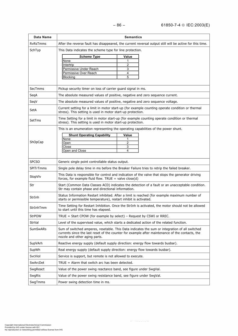
– 86 – 61850-7-4 IEC:2003(E)
Data Name Semantics
RvRsTmms After the reverse fault has disappeared, the current reversal output still will be active for this time.
SchTyp This Data indicates the scheme type for line protection.
Scheme Type Value None 1 Intertrip 2 Permissive Under Reach 3 Permissive Over Reach 4 Blocking 5
SecTmms Pickup security timer on loss of carrier guard signal in ms.
SeqA The absolute measured values of positive, negative and zero sequence current.
SeqV The absolute measured values of positive, negative and zero sequence voltage.
SetA Current setting for a limit in motor start-up (for example counting operate condition or thermalstress). This setting is used in motor start-up protection.
SetTms Time Setting for a limit in motor start-up (for example counting operate condition or thermalstress). This setting is used in motor start-up protection.
ShOpCap
This is an enumeration representing the operating capabilities of the power shunt.
Shunt Operating Capability ValueNone 1Open 2Close 3Open and Close 4
SPCSO Generic single point controllable status output.
SPlTrTmms Single pole delay time in ms before the Breaker Failure tries to retrip the failed breaker.
StopVlv This Data is responsible for control and indication of the valve that stops the generator drivingforces, for example fluid flow. TRUE = valve close(d)
Str Start (Common Data Classes ACD) indicates the detection of a fault or an unacceptable condition.Str may contain phase and directional information.
StrInh Status Information Restart inhibited. After a limit is reached (for example maximum number ofstarts or permissible temperature), restart inhibit is activated.
StrInhTmm Time Setting for Restart Inhibition. Once the StrInh is activated, the motor should not be allowedto start until this time has elapsed.
StrPOW TRUE = Start CPOW (for example by select) – Request by CSWI or RREC.
StrVal Level of the supervised value, which starts a dedicated action of the related function.
SumSwARs Sum of switched amperes, resetable. This Data indicates the sum or integration of all switchedcurrents since the last reset of the counter for example after maintenance of the contacts, thenozzle and other aging parts.
SupVArh Reactive energy supply (default supply direction: energy flow towards busbar).
SupWh Real energy supply (default supply direction: energy flow towards busbar).
SvcViol Service is support, but remote is not allowed to execute.
SwArcDet TRUE = Alarm that switch arc has been detected.
SwgReact Value of the power swing reactance band, see figure under SwgVal.
SwgRis Value of the power swing resistance band, see figure under SwgVal.
SwgTmms Power swing detection time in ms.
Copyright International Electrotechnical Commission Provided by IHS under license with IEC
Not for ResaleNo reproduction or networking permitted without license from IHS
--``````-`-`,,`,,`,`,,`---
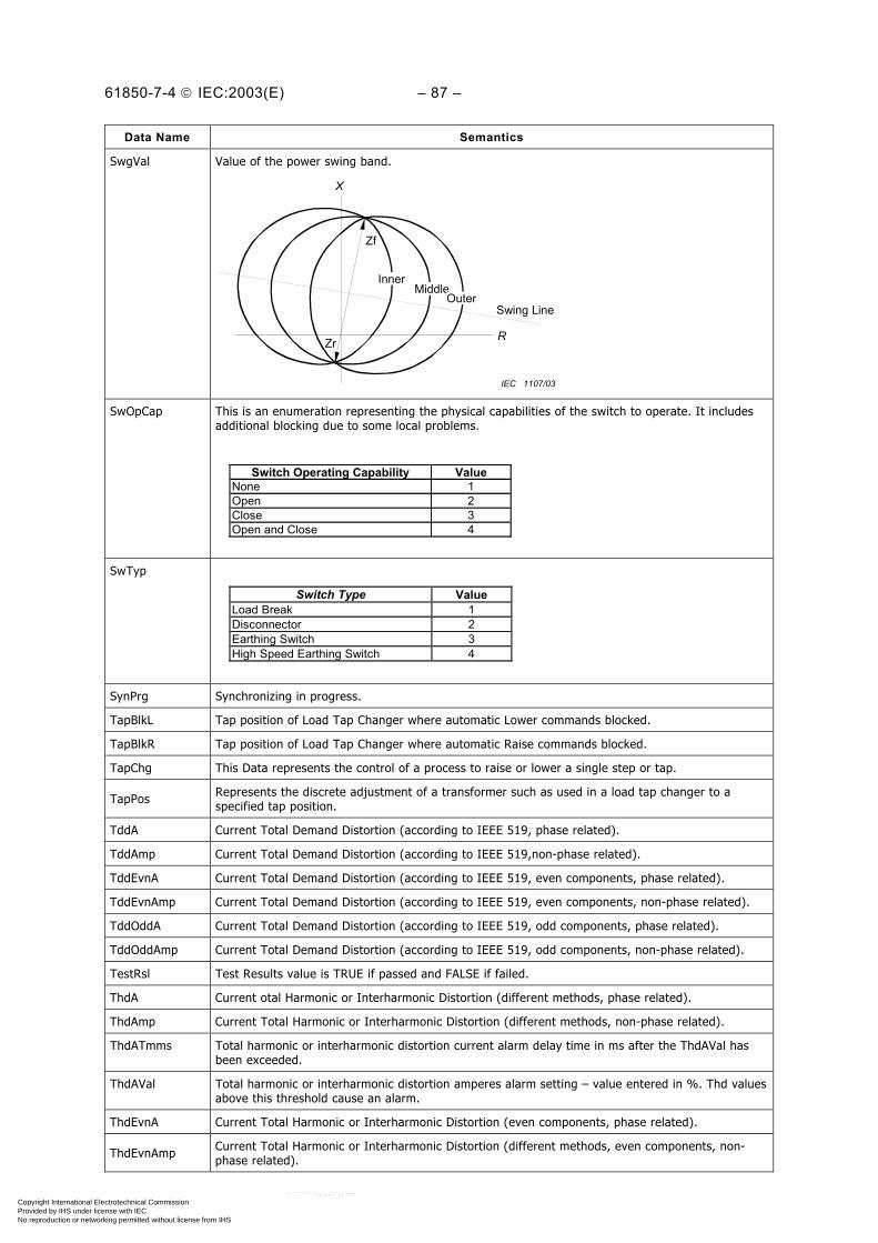
61850-7-4 IEC:2003(E) – 87 –
Data Name Semantics
SwgVal Value of the power swing band.
X
R
Zf
Zr
InnerMidleMiddle
OuterSwing Line
IEC 1107/03
SwOpCap This is an enumeration representing the physical capabilities of the switch to operate. It includesadditional blocking due to some local problems.
Switch Operating Capability ValueNone 1Open 2Close 3Open and Close 4
SwTyp
Switch Type Value Load Break 1 Disconnector 2 Earthing Switch 3 High Speed Earthing Switch 4
SynPrg Synchronizing in progress.
TapBlkL Tap position of Load Tap Changer where automatic Lower commands blocked.
TapBlkR Tap position of Load Tap Changer where automatic Raise commands blocked.
TapChg This Data represents the control of a process to raise or lower a single step or tap.
TapPos Represents the discrete adjustment of a transformer such as used in a load tap changer to aspecified tap position.
TddA Current Total Demand Distortion (according to IEEE 519, phase related).
TddAmp Current Total Demand Distortion (according to IEEE 519,non-phase related).
TddEvnA Current Total Demand Distortion (according to IEEE 519, even components, phase related).
TddEvnAmp Current Total Demand Distortion (according to IEEE 519, even components, non-phase related).
TddOddA Current Total Demand Distortion (according to IEEE 519, odd components, phase related).
TddOddAmp Current Total Demand Distortion (according to IEEE 519, odd components, non-phase related).
TestRsl Test Results value is TRUE if passed and FALSE if failed.
ThdA Current otal Harmonic or Interharmonic Distortion (different methods, phase related).
ThdAmp Current Total Harmonic or Interharmonic Distortion (different methods, non-phase related).
ThdATmms Total harmonic or interharmonic distortion current alarm delay time in ms after the ThdAVal hasbeen exceeded.
ThdAVal Total harmonic or interharmonic distortion amperes alarm setting – value entered in %. Thd valuesabove this threshold cause an alarm.
ThdEvnA Current Total Harmonic or Interharmonic Distortion (even components, phase related).
ThdEvnAmp Current Total Harmonic or Interharmonic Distortion (different methods, even components, non-phase related).
Copyright International Electrotechnical Commission Provided by IHS under license with IEC
Not for ResaleNo reproduction or networking permitted without license from IHS
--``````-`-`,,`,,`,`,,`---
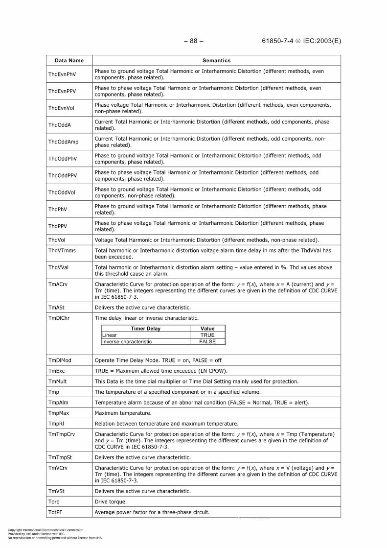
– 88 – 61850-7-4 IEC:2003(E)
Data Name Semantics
ThdEvnPhV Phase to ground voltage Total Harmonic or Interharmonic Distortion (different methods, evencomponents, phase related).
ThdEvnPPV Phase to phase voltage Total Harmonic or Interharmonic Distortion (different methods, evencomponents, phase related).
ThdEvnVol Phase voltage Total Harmonic or Interharmonic Distortion (different methods, even components,non-phase related).
ThdOddA Current Total Harmonic or Interharmonic Distortion (different methods, odd components, phaserelated).
ThdOddAmp Current Total Harmonic or Interharmonic Distortion (different methods, odd components, non-phase related).
ThdOddPhV Phase to ground voltage Total Harmonic or Interharmonic Distortion (different methods, oddcomponents, phase related).
ThdOddPPV Phase to phase voltage Total Harmonic or Interharmonic Distortion (different methods, oddcomponents, phase related).
ThdOddVol Phase to ground voltage Total Harmonic or Interharmonic Distortion (different methods, oddcomponents, non-phase related).
ThdPhV Phase to ground voltage Total Harmonic or Interharmonic Distortion (different methods, phaserelated).
ThdPPV Phase to phase voltage Total Harmonic or Interharmonic Distortion (different methods, phaserelated).
ThdVol Voltage Total Harmonic or Interharmonic Distortion (different methods, non-phase related).
ThdVTmms Total harmonic or Interharmonic distortion voltage alarm time delay in ms after the ThdVVal hasbeen exceeded.
ThdVVal Total harmonic or Interharmonic distortion alarm setting – value entered in %. Thd values abovethis threshold cause an alarm.
TmACrv Characteristic Curve for protection operation of the form: y = f(x), where x = A (current) and y =Tm (time). The integers representing the different curves are given in the definition of CDC CURVEin IEC 61850-7-3.
TmASt Delivers the active curve characteristic.
TmDlChr Time delay linear or inverse characteristic.
Timer Delay ValueLinear TRUEInverse characteristic FALSE
TmDlMod Operate Time Delay Mode. TRUE = on, FALSE = off
TmExc TRUE = Maximum allowed time exceeded (LN CPOW).
TmMult This Data is the time dial multiplier or Time Dial Setting mainly used for protection.
Tmp The temperature of a specified component or in a specified volume.
TmpAlm Temperature alarm because of an abnormal condition (FALSE = Normal, TRUE = alert).
TmpMax Maximum temperature.
TmpRl Relation between temperature and maximum temperature.
TmTmpCrv Characteristic Curve for protection operation of the form: y = f(x), where x = Tmp (Temperature)and y = Tm (time). The integers representing the different curves are given in the definition ofCDC CURVE in IEC 61850-7-3.
TmTmpSt Delivers the active curve characteristic.
TmVCrv Characteristic Curve for protection operation of the form: y = f(x), where x = V (voltage) and y =Tm (time). The integers representing the different curves are given in the definition of CDC CURVEin IEC 61850-7-3.
TmVSt Delivers the active curve characteristic.
Torq Drive torque.
TotPF Average power factor for a three-phase circuit.
Copyright International Electrotechnical Commission Provided by IHS under license with IEC
Not for ResaleNo reproduction or networking permitted without license from IHS
--``````-`-`,,`,,`,`,,`---

61850-7-4 IEC:2003(E) – 89 –
Data Name Semantics
TotVA Total apparent power in a three-phase circuit.
TotVAh Net Apparent energy since last rest.
TotVAr Total reactive power in a three-phase circuit.
TotVArh Net Reactive energy since last reset.
TotW Total real power in a three phase circuit.
TotWh Net Real energy since last reset.
TPTrTmms Three-pole delay time in ms before the Breaker Failure tries to retrip the failed breaker.
Tr Trip is the command to open the breaker when issued in case of fault by PTRC.
TrgMod Disturbance recorder trigger mode. The source of the External trigger is a local issue.
Trigger Mode ValueInternal 1External 2Both 3
TrMod This data represents type of trip function; 3ph means only 3phase tripping possible, 1 or 3phmeans PTRC with 1 and 3 phase tripping possibility and first trip depending on fault type. Specificmeans for example PTRC with 1 and 2ph and 3ph tripping possibility and first trip depending onfault type.
Trip Mode Value3 phase tripping 11 or 3 phase tripping 2specific 3
TrPlsTmms Trip pulse time is the minimum pulse time for breaker operation.
TypRsCrv This is the type of the reset curve that is used to co-ordinate the reset with electromechanicalrelays that do not reset instantaneously.
Reset Curve ValueNone 1Definite Time Delayed Reset 2Inverse Reset 3
UnBlkMod
This Data is the unblock function mode.
Unblock Function Mode ValueOff 1Permanent 2Time Window 3
UnBlkTmms Unblocking Time.
VHzCrv Characteristic Curve for protection operation of the form: y = f(x), where x = Hz (frequency) and y= V (voltage) The integers representing the different curves are given in the definition of CDCCURVE in IEC 61850-7-3.
VHzSt Delivers the active curve characteristic.
VInd This Data indicates the check result of the differences between the absolute values of the busbarand line voltages. FALSE indicates that the voltage difference is below the required limit. Thevoltage difference criteria for the synchronising are fulfilled. TRUE indicates that the voltagedifference exceeds the limit. The synchronising process shall be aborted because the voltage bandcriteria are not fulfilled (synchrocheck) or shall be continued with generator control activities(synchronising).
Vol Voltage non phase related.
VolAmp Apparent power measurement of a non-three-phase circuit.
VolAmpr Volt-amperes reactive of a non-three-phase circuit.
VolChgRte Rate of voltage change (change over time).
VOvSt TRUE = Indicates voltage override control status.
Copyright International Electrotechnical Commission Provided by IHS under license with IEC
Not for ResaleNo reproduction or networking permitted without license from IHS
--``````-`-`,,`,,`,`,,`---
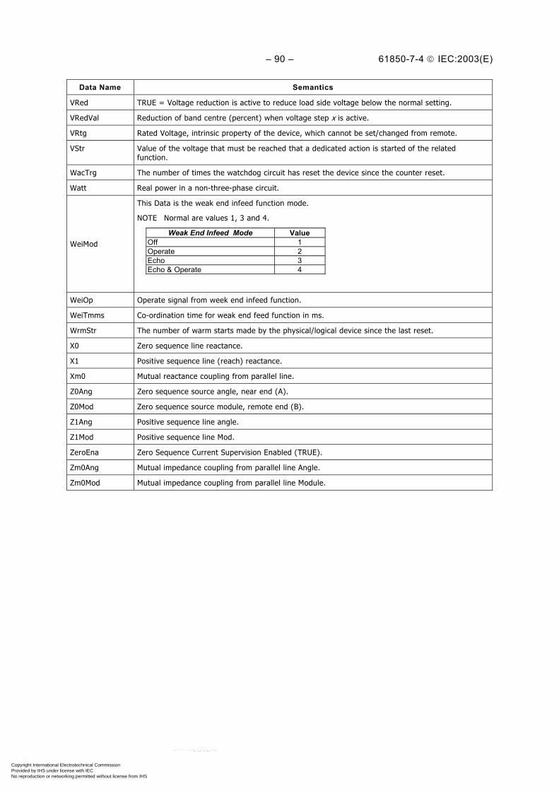
– 90 – 61850-7-4 IEC:2003(E)
Data Name Semantics
VRed TRUE = Voltage reduction is active to reduce load side voltage below the normal setting.
VRedVal Reduction of band centre (percent) when voltage step x is active.
VRtg Rated Voltage, intrinsic property of the device, which cannot be set/changed from remote.
VStr Value of the voltage that must be reached that a dedicated action is started of the relatedfunction.
WacTrg The number of times the watchdog circuit has reset the device since the counter reset.
Watt Real power in a non-three-phase circuit.
WeiMod
This Data is the weak end infeed function mode.
NOTE Normal are values 1, 3 and 4.
Weak End Infeed Mode ValueOff 1Operate 2Echo 3Echo & Operate 4
WeiOp Operate signal from week end infeed function.
WeiTmms Co-ordination time for weak end feed function in ms.
WrmStr The number of warm starts made by the physical/logical device since the last reset.
X0 Zero sequence line reactance.
X1 Positive sequence line (reach) reactance.
Xm0 Mutual reactance coupling from parallel line.
Z0Ang Zero sequence source angle, near end (A).
Z0Mod Zero sequence source module, remote end (B).
Z1Ang Positive sequence line angle.
Z1Mod Positive sequence line Mod.
ZeroEna Zero Sequence Current Supervision Enabled (TRUE).
Zm0Ang Mutual impedance coupling from parallel line Angle.
Zm0Mod Mutual impedance coupling from parallel line Module.
Copyright International Electrotechnical Commission Provided by IHS under license with IEC
Not for ResaleNo reproduction or networking permitted without license from IHS
--``````-`-`,,`,,`,`,,`---

61850-7-4 IEC:2003(E) – 91 –
Annex A (normative)
Extension rules
A.1 The use of Logical Nodes and Data and its extensions
A.1.1 Basic rules
A.1.1.1 Logical Nodes (LN)• If there is any Logical Nodes Class which fits the function to be modelled, an instance of
this logical node shall be used with all its mandatory data (M). The rules of a uniqueinstantiation can be found in IEC 61850-7-2.
• If there are dedicated versions of this function with the same basic data (for exampleground, phase, zone A, zone B, etc.), different instances of this Logical Node Class shall beused.
• If there are no Logical Nodes Classes which fit to the function to be modelled, a new logicalnode shall be created according to the rules for new Logical Nodes, see A.4.
• Other extensions are not allowed in the domain of substation automation.
A.1.1.2 Data• If, in addition to the mandatory data (M), there are also optional data (O), which fit the
function to be modelled, these optional data shall be used.
• If there are same data (M or O) which are needed more times than defined in the LogicalNode Class, additional data with number extensions shall be used.
• If, in the Logical Node Class, data are missing for the allocated function, the first choiceshall be to use one of the data listed in Clause 6.
• If none of the data in Clause 6 covers the open requirement of the function, new data shallbe created according to the rules for new data (see A.6).
• Other extensions are not allowed in the domain of substation automation.
A.2 Multiple instances of LN classes for dedicated and complex functions
A.2.1 Example for time overcurrent
Logical Node Class Name: PTOC (Time overcurrent)
LN Instance Name Meaning Meaning of “Start value”StrVal
GFDPTOC Ground Fault Detection “Ground Start Value”
PFDPTOC Phase Fault Detection “Phase Start Value”
A.2.2 Example for Distance
Logical Node Class Name: PDIS (Distance)
LN Instance Name(without LN-Prefix) Meaning
PDIS1 Zone 1 of the distance protection
PDIS2 Zone 2 of the distance protection
PDIS3 Zone 3 of the distance protection
etc. etc.
Copyright International Electrotechnical Commission Provided by IHS under license with IEC
Not for ResaleNo reproduction or networking permitted without license from IHS
--``````-`-`,,`,,`,`,,`---

– 92 – 61850-7-4 IEC:2003(E)
The semantics of the different instances may be given in the description attribute of dataNamPlt (Name Plate). Instances of PSCH co-ordinate the “start” (Str) and “operate” (Op)according to the protection scheme. This co-ordination includes the PDIS functions on bothsides of the line. The result of the co-ordination is a trip via PTRC to the local circuit breaker(see example in B.2).
A.2.3 Example for Power transformer
Logical Node Class Name: YPTR (Power transformer)
LN Instance Name(without LN-Prefix) Meaning
YPTR1 Transformer unit phase L1
YPTR2 Transformer unit phase L2
YPTR3 Transformer unit phase L3
The semantics of the different instances may be given in the description attribute of dataNamPlt (Name Plate).
A.2.4 Example for Auxiliary network
Logical Node Class Name: ZAXN (Auxiliary network)
LN Instance Name(without LN-Prefix) Meaning
ZAXN1 220 V DC
ZAXN2 60 V DC
ZAXN3 380 V AC
The semantics of the different instances may be given in the description attribute of dataNamPlt (Name Plate).
A.3 Specialisation of Data by use of the number extension
Standardised data names in Logical Nodes provide a unique identification. If the same data(i.e. data with the same semantics) are needed more times as defined, additional data withnumber extensions shall be used. Examples are given in the following.
Logical Node Class Name: YPTR (Power transformer)
Data name: HPTmp (Winding hotspot temperature in °C)
HPTmp1 Winding hotspot 1 temperature (in °C)
HPTmp2 Winding hotspot 2 temperature (in °C)
HPTmp3 Winding hotspot 3 temperature (in °C)
HPTmp4 Winding hotspot 4 temperature (in °C)
The semantics of the different hot spots may be given in the description attribute of the data.
A.4 Rules for names of new Logical Nodes
If no standardised Logical Node class is applicable for the function to be modelled a new classwith a new name may be created. To keep interoperability simple this option shall be used withcare. A new Logical Node class name shall be created by use of the following namingconventions:
• The first character shall be chosen in accordance with the relevant prefix of the LogicalNode group (see Table 1) if applicable.
Copyright International Electrotechnical Commission Provided by IHS under license with IEC
Not for ResaleNo reproduction or networking permitted without license from IHS
--``````-`-`,,`,,`,`,,`---

61850-7-4 IEC:2003(E) – 93 –
• The other characters shall be defined in relation to the English name of the new LN classname.
• New Logical Node classes shall be marked by a “name space attribute” according to theconcept and rules given in IEC 61850-7-1 and to the attributes given in IEC 61850-7-3.
The creator of the new Logical Node class shall ensure that each additional name is consistentwith the mnemonic naming conventions of the standardised LN classes and unique in thesubstation automation system considered. The description of this new Logical Node Class shallbe added to the IEC documentation of the provider specific system or customer specificproject.
A.5 Examples for new LNs
A.5.1 New LN “Automatic door entrance control”1. CharacterLogical Node Group Indication
2. Character 3. Character 4. Character new LN
A for “Automatic Control” Door Entrance Control ADEC“Automatic doorentrance control”
A.5.2 New LN “Fire protection”1. CharacterLogical Node Group Indication
2. Character 3. Character 4. Character new LN
Z for “ Further equipment” Fire Protection Transformer ZFPT“Fire Protection ofa powertransformer”
A.6 Rules for names of new Data
When in a standardised LN, data are missing or for a new LN data are needed, the data namesfrom Clause 6 shall be used if applicable. If no standardised data fulfils the needs for a specialinstance of a standardised LN class, a “new” data may be created. To keep interoperabilitysimple, this option shall be used with care. In any case, the following rules shall be followed:
• For building the new Data name, the abbreviations of Clause 4 shall be used if applicable.Only in other cases are new abbreviations out of the English name for the data allowed.
• The Data shall be assigned to any of the Common Data Classes as defined in IEC 61850-7-3.If no standardised Common Data Class fulfills the needs of the new data, an extended ornew data class may be used (see A.8).
• Any data name shall be allocated to one Common Data Class (CDC) only.
• New Data names shall be marked by a “name space attribute” according to the concept andrules given in IEC 61850-7-1 and to the attributes given in IEC 61850-7-3.
The creator of new data shall ensure that each additional name is consistent with themnemonic naming conventions of the standardised data names and unique in the substationautomation system considered. The description of the new data shall be published to the userof the dedicated substation automation system.
A.7 Example for new Data
New Data “Colour of Transformer Oil”
New Data name: ColrTOil Attribute Type (CDC): INS (Integer status)
Copyright International Electrotechnical Commission Provided by IHS under license with IEC
Not for ResaleNo reproduction or networking permitted without license from IHS
--``````-`-`,,`,,`,`,,`---
– 94 – 61850-7-4 IEC:2003(E)
A.8 Rules for new Common Data Classes (CDC)
When for new data names, an appropriate CDC is missing the existing CDC can be extendedor a new CDC may be created. To keep interoperability simple, this option shall be used withcare. The rules for creating new CDC are defined in IEC 61850-7-3. New CDC shall be markedby a “name space attribute” according to the concept and rules given in IEC 61850-7-1 and tothe attributes given in IEC 61850-7-3.
The creator of new CDC shall ensure that each additional CDC is consistent with themnemonic naming conventions of the standardised CDC and unique in the substationautomation system considered. The description of the new CDC shall be published to the userof the dedicated substation automation system.
Copyright International Electrotechnical Commission Provided by IHS under license with IEC
Not for ResaleNo reproduction or networking permitted without license from IHS
--``````-`-`,,`,,`,`,,`---
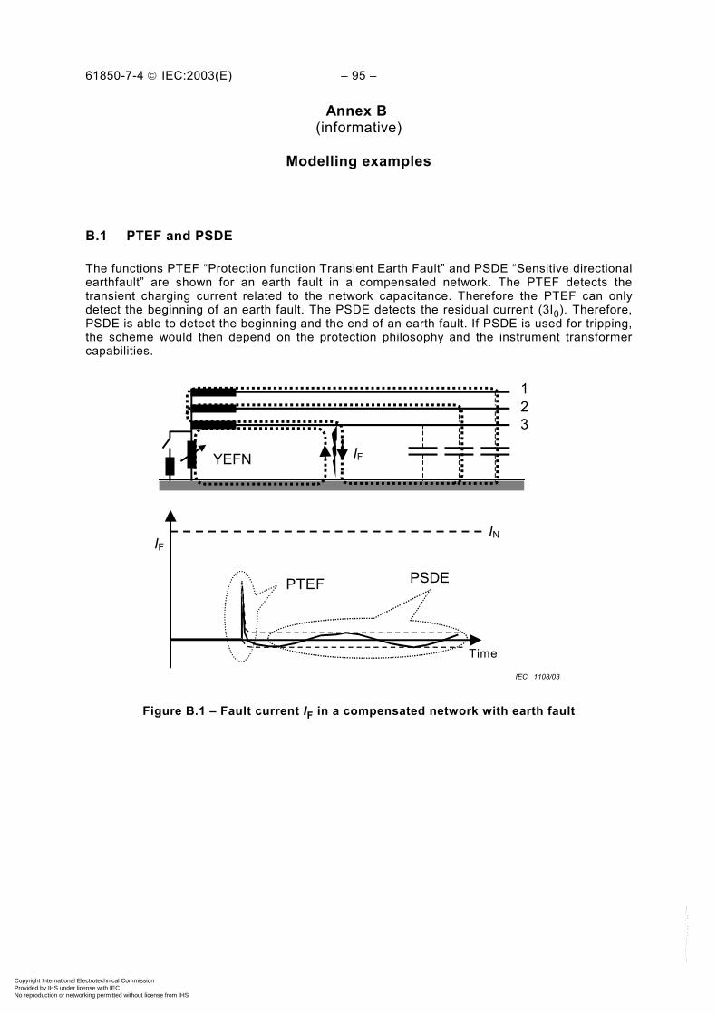
61850-7-4 IEC:2003(E) – 95 –
Annex B (informative)
Modelling examples
B.1 PTEF and PSDE
The functions PTEF “Protection function Transient Earth Fault” and PSDE “Sensitive directionalearthfault” are shown for an earth fault in a compensated network. The PTEF detects thetransient charging current related to the network capacitance. Therefore the PTEF can onlydetect the beginning of an earth fault. The PSDE detects the residual current (3I0). Therefore,PSDE is able to detect the beginning and the end of an earth fault. If PSDE is used for tripping,the scheme would then depend on the protection philosophy and the instrument transformercapabilities.
123
IFYEFN
PSDEPTEF
Time
YEFN IF
IFIN
123
IEC 1108/03
Figure B.1 – Fault current IF in a compensated network with earth fault
Copyright International Electrotechnical Commission Provided by IHS under license with IEC
Not for ResaleNo reproduction or networking permitted without license from IHS
--``````-`-`,,`,,`,`,,`---

– 96 – 61850-7-4 IEC:2003(E)
B.2 PSCH and PTRC
PSCH is used for modelling typical schemes in multifunctional IEDs for line protection. Thedata provided allow its use for modelling of different communications based acceleratingschemes for transmission line protection.
PSCH may exchange data with many Logical Nodes (PDIS, PTOC,…, other PSCH). All theseLogical Nodes may be located in different Logical Devices and Physical Devices (IEDs). PTRCis used to combine and condition various signals intended for tripping into a single tripcondition.
The example in Figure B.2 illustrates a line protection scheme consisting of functions fordistance protection (three instances for three zones) with teleprotection (PDIS + PSCH), fordirectional earth fault comparison protection (PTOC2) and for back up overcurrent protection(PTOC1) on both ends of the line.
PDISPDISPDISPDIS
PTRC
PSCH2
PTOC2PTOC1
Substation A
PSCH1
PDIS
PTRC
PSCH1
PDIS PTOC1
Substation B
PSCH2
XCBRXCBR
PTOC2
IEC 1109/03
Figure B.2 – Use of PSCH and PTRC
The teleprotection functions (permissive overreach, permissive under reach, blocking,unblocking, etc.) of the distance protection and of the directional earth fault comparisonscheme are concentrated in the logical nodes instances PSCH1 and PSCH2 of LN PSCH.These logical nodes control the communication between the two line ends.
All operate signals coming from the PSCH-nodes and from the protection nodes without anadditional PSCH-node are combined to a trip-command in one PTRC. PTRC handles the tripsignal conditioning (minimum trip command duration, single/three-pole decision, etc).
Copyright International Electrotechnical Commission Provided by IHS under license with IEC
Not for ResaleNo reproduction or networking permitted without license from IHS
--``````-`-`,,`,,`,`,,`---
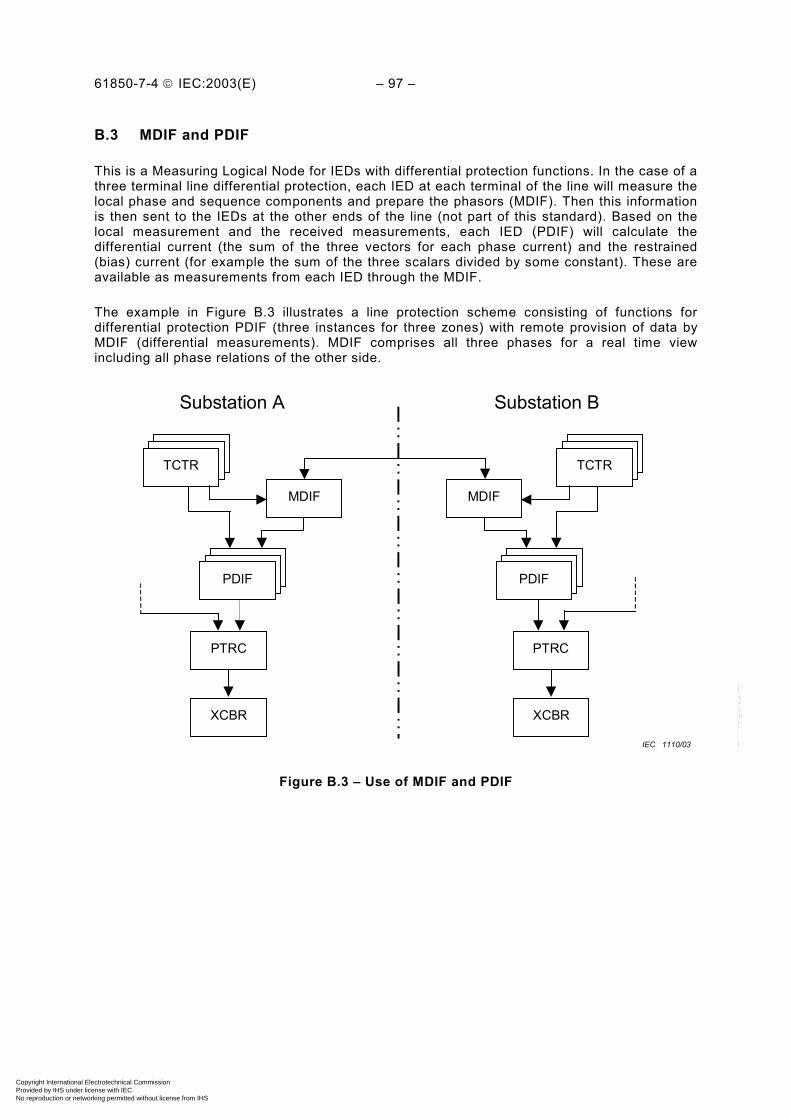
61850-7-4 IEC:2003(E) – 97 –
B.3 MDIF and PDIF
This is a Measuring Logical Node for IEDs with differential protection functions. In the case of athree terminal line differential protection, each IED at each terminal of the line will measure thelocal phase and sequence components and prepare the phasors (MDIF). Then this informationis then sent to the IEDs at the other ends of the line (not part of this standard). Based on thelocal measurement and the received measurements, each IED (PDIF) will calculate thedifferential current (the sum of the three vectors for each phase current) and the restrained(bias) current (for example the sum of the three scalars divided by some constant). These areavailable as measurements from each IED through the MDIF.
The example in Figure B.3 illustrates a line protection scheme consisting of functions fordifferential protection PDIF (three instances for three zones) with remote provision of data byMDIF (differential measurements). MDIF comprises all three phases for a real time viewincluding all phase relations of the other side.
Substation A Substation B
PTRC
XCBR
PTRC
XCBR
PDISPDISPDIF
PDISPDISTCTR
MDIF
PDISPDISPDIF
MDIF
PDISPDISTCTR
IEC 1110/03
Figure B.3 – Use of MDIF and PDIF
Copyright International Electrotechnical Commission Provided by IHS under license with IEC
Not for ResaleNo reproduction or networking permitted without license from IHS
--``````-`-`,,`,,`,`,,`---
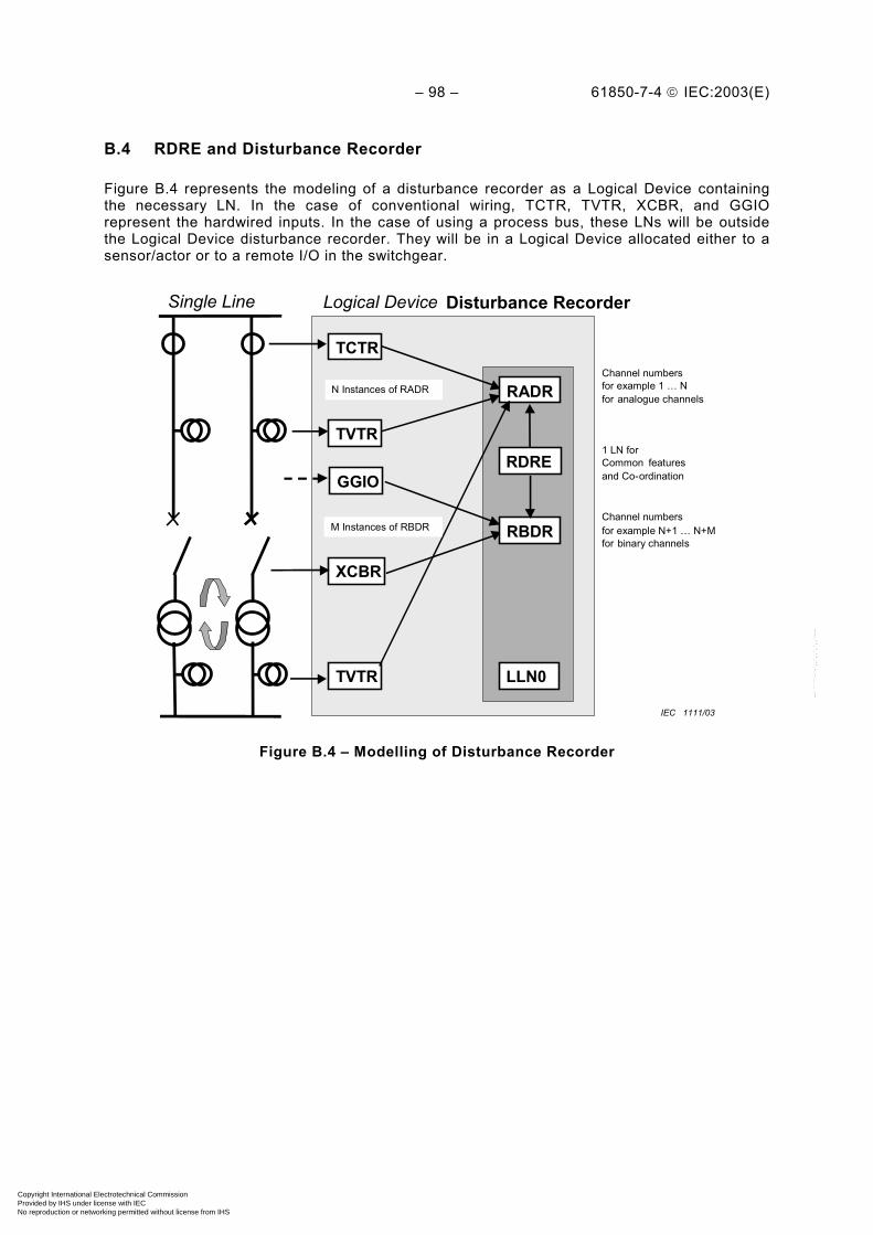
– 98 – 61850-7-4 IEC:2003(E)
B.4 RDRE and Disturbance Recorder
Figure B.4 represents the modeling of a disturbance recorder as a Logical Device containingthe necessary LN. In the case of conventional wiring, TCTR, TVTR, XCBR, and GGIOrepresent the hardwired inputs. In the case of using a process bus, these LNs will be outsidethe Logical Device disturbance recorder. They will be in a Logical Device allocated either to asensor/actor or to a remote I/O in the switchgear.
TCTR
XCBR
RADR
RDRE
RBDR
TVTR LLN0
Logical Device Disturbance RecorderSingle Line
TVTR
N Instances of RADR
M Instances of RBDR
GGIO
Channel numbersfor example 1 … Nfor analogue channels
Channel numbersfor example N+1 … N+Mfor binary channels
1 LN forCommon featuresand Co-ordination
IEC 1111/03
Figure B.4 – Modelling of Disturbance Recorder
Copyright International Electrotechnical Commission Provided by IHS under license with IEC
Not for ResaleNo reproduction or networking permitted without license from IHS
--``````-`-`,,`,,`,`,,`---

61850-7-4 IEC:2003(E) – 99 –
B.5 PTRC
The example in Figure B.5 shows the different allocation of Logical Nodes (LN) to devices(IED). The Logical Nodes involved are PTOC (Time overcurrent protection), PDIS (DistanceProtection), PTRC (Trip Conditioning) and XCBR (Circuit Breaker). Case (a) shows aprotection device with two functions, which is hardwired connected with the circuit breaker.Case (b) shows a protection device with two functions where the Trip goes as a GSE-messageover the process bus to the circuit breaker. Case (c) shows the two protection functions indedicated devices, which may operate both in a fault and where the trips are transmitted asGSE-messages over the process bus independently to the circuit breaker IED (XCBR).
PTOC PDIS
PTRC
XCBR
IED
Circuit Breaker
PTOC PDIS
PTRC
XCBR
(a) (b) (c)
PTOC PDIS
“Wires“Trip
“GSE“Trip
IED IED IED
PTRC PTRC
XCBR
IED IED
“GSE“Trip
Figure B.5 – Examples for allocation of Logical Nodes to IEDs
IEC 1112/03
Copyright International Electrotechnical Commission Provided by IHS under license with IEC
Not for ResaleNo reproduction or networking permitted without license from IHS
--``````-`-`,,`,,`,`,,`---
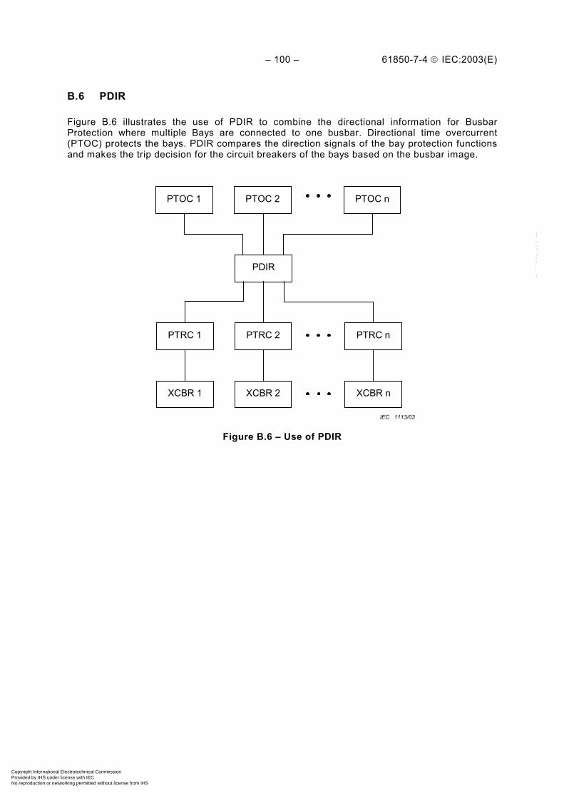
– 100 – 61850-7-4 IEC:2003(E)
B.6 PDIR
Figure B.6 illustrates the use of PDIR to combine the directional information for BusbarProtection where multiple Bays are connected to one busbar. Directional time overcurrent(PTOC) protects the bays. PDIR compares the direction signals of the bay protection functionsand makes the trip decision for the circuit breakers of the bays based on the busbar image.
PDIR
PTOC 1
XCBR 2
PTRC 2
XCBR nXCBR 1
PTRC nPTRC 1
PTOC 2 PTOC n
IEC 1113/03
Figure B.6 – Use of PDIR
Copyright International Electrotechnical Commission Provided by IHS under license with IEC
Not for ResaleNo reproduction or networking permitted without license from IHS
--``````-`-`,,`,,`,`,,`---

61850-7-4 IEC:2003(E) – 101 –
B.7 RREC
Figure B.7 illustrates the use of the autoreclosure LN RREC in co-operation with a protectionLN (LN PTOC), the control LN CSWI and the circuit breaker LN XCBR. Case (a) shows theconventional scheme, where no process bus is used. The autoreclosure LN RREC isimplemented in the protection IED and the controller CSWI in an independent bay level IED.The operator’s place is indicated as LN IHMI. In case (b) the autoreclosure is located ina dedicated IED and the circuit breaker connected with a process bus. If no services withreal-time capability are available between RREC and CSWI on one side and XCBR on theother side, the opening and (re-)closing commands are performed with a GSE-message(see IEC 61850-7-2).
IED
(a)
PTOC
PTRC
XCBR
Circuit Breaker
“Wires“Tripand
Close
RREC
Trip
(Re-)Close
IHMI
IED
CSWI
XCBR
“Wires“Tripand
Close
Trip
IED
IED
(b)
IED
PTOC
PTRC
XCBR
RREC
IED
IHMI
IED
CSWI
IED
“GSE“ Trip
“Report” Tripor“GSE“ Trip
“Control” Service
“Control” Serviceor
“GSE” Close
Figure B.7 – Use of RREC
IEC 1114/03
Copyright International Electrotechnical Commission Provided by IHS under license with IEC
Not for ResaleNo reproduction or networking permitted without license from IHS
--``````-`-`,,`,,`,`,,`---
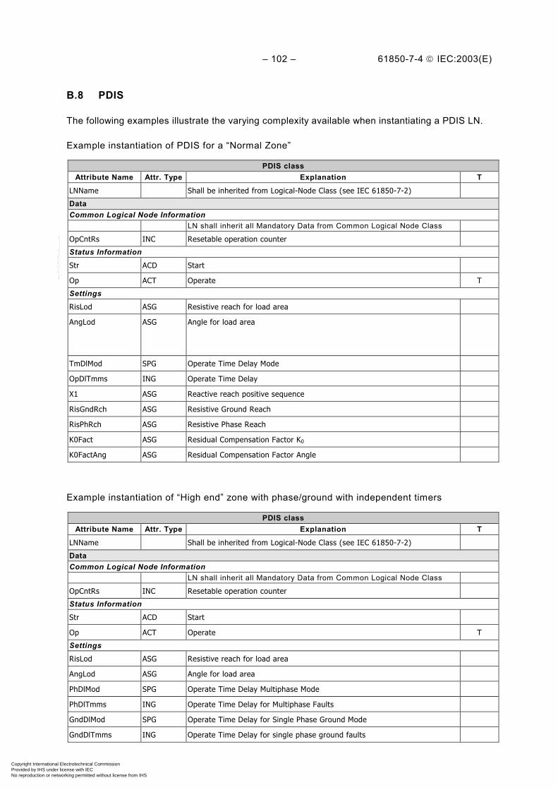
– 102 – 61850-7-4 IEC:2003(E)
B.8 PDIS
The following examples illustrate the varying complexity available when instantiating a PDIS LN.
Example instantiation of PDIS for a “Normal Zone”
PDIS classAttribute Name Attr. Type Explanation T
LNName Shall be inherited from Logical-Node Class (see IEC 61850-7-2)
DataCommon Logical Node Information
LN shall inherit all Mandatory Data from Common Logical Node Class
OpCntRs INC Resetable operation counter
Status Information
Str ACD Start
Op ACT Operate T
Settings
RisLod ASG Resistive reach for load area
AngLod ASG Angle for load area
TmDlMod SPG Operate Time Delay Mode
OpDlTmms ING Operate Time Delay
X1 ASG Reactive reach positive sequence
RisGndRch ASG Resistive Ground Reach
RisPhRch ASG Resistive Phase Reach
K0Fact ASG Residual Compensation Factor K0
K0FactAng ASG Residual Compensation Factor Angle
Example instantiation of “High end” zone with phase/ground with independent timers
PDIS classAttribute Name Attr. Type Explanation T
LNName Shall be inherited from Logical-Node Class (see IEC 61850-7-2)
DataCommon Logical Node Information
LN shall inherit all Mandatory Data from Common Logical Node Class
OpCntRs INC Resetable operation counter
Status Information
Str ACD Start
Op ACT Operate T
Settings
RisLod ASG Resistive reach for load area
AngLod ASG Angle for load area
PhDlMod SPG Operate Time Delay Multiphase Mode
PhDlTmms ING Operate Time Delay for Multiphase Faults
GndDlMod SPG Operate Time Delay for Single Phase Ground Mode
GndDlTmms ING Operate Time Delay for single phase ground faults
Copyright International Electrotechnical Commission Provided by IHS under license with IEC
Not for ResaleNo reproduction or networking permitted without license from IHS
--``````-`-`,,`,,`,`,,`---
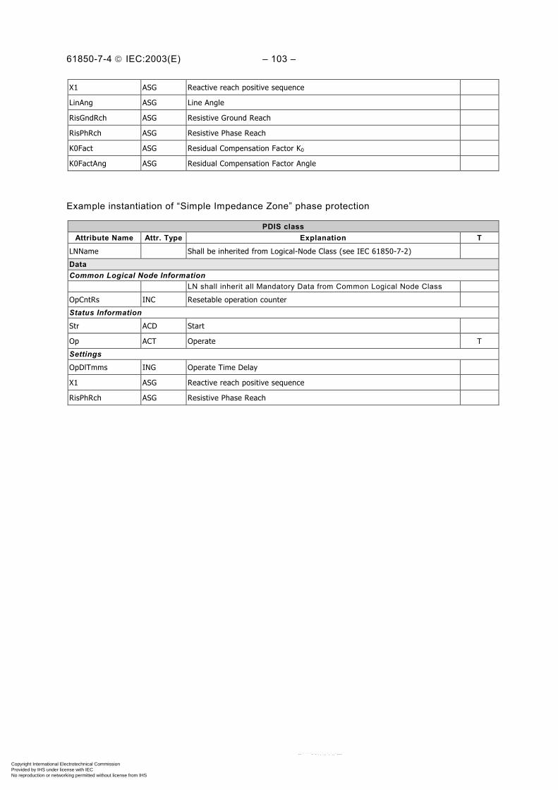
61850-7-4 IEC:2003(E) – 103 –
X1 ASG Reactive reach positive sequence
LinAng ASG Line Angle
RisGndRch ASG Resistive Ground Reach
RisPhRch ASG Resistive Phase Reach
K0Fact ASG Residual Compensation Factor K0
K0FactAng ASG Residual Compensation Factor Angle
Example instantiation of “Simple Impedance Zone” phase protection
PDIS classAttribute Name Attr. Type Explanation T
LNName Shall be inherited from Logical-Node Class (see IEC 61850-7-2)
DataCommon Logical Node Information
LN shall inherit all Mandatory Data from Common Logical Node Class
OpCntRs INC Resetable operation counter
Status Information
Str ACD Start
Op ACT Operate T
Settings
OpDlTmms ING Operate Time Delay
X1 ASG Reactive reach positive sequence
RisPhRch ASG Resistive Phase Reach
Copyright International Electrotechnical Commission Provided by IHS under license with IEC
Not for ResaleNo reproduction or networking permitted without license from IHS
--``````-`-`,,`,,`,`,,`---
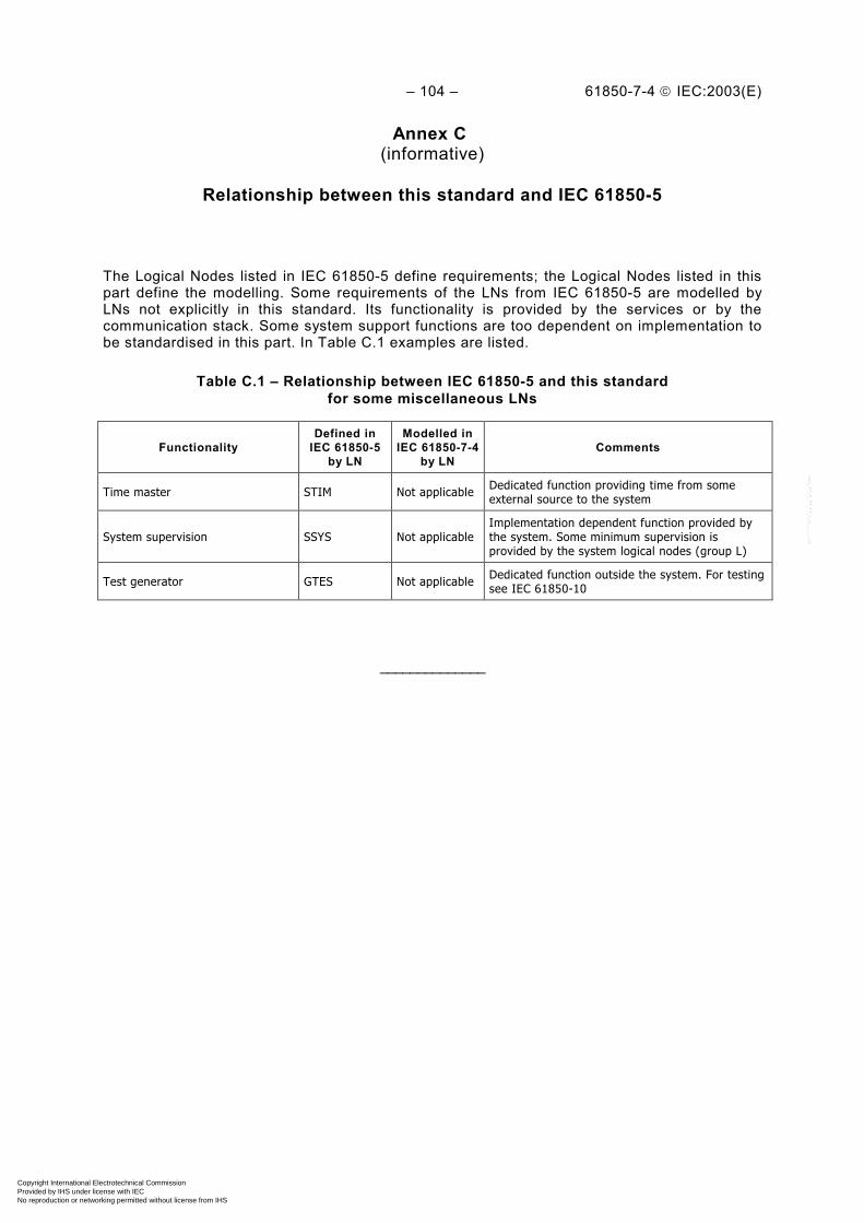
– 104 – 61850-7-4 IEC:2003(E)
Annex C (informative)
Relationship between this standard and IEC 61850-5
The Logical Nodes listed in IEC 61850-5 define requirements; the Logical Nodes listed in thispart define the modelling. Some requirements of the LNs from IEC 61850-5 are modelled byLNs not explicitly in this standard. Its functionality is provided by the services or by thecommunication stack. Some system support functions are too dependent on implementation tobe standardised in this part. In Table C.1 examples are listed.
Table C.1 – Relationship between IEC 61850-5 and this standardfor some miscellaneous LNs
FunctionalityDefined in
IEC 61850-5by LN
Modelled inIEC 61850-7-4
by LNComments
Time master STIM Not applicable Dedicated function providing time from someexternal source to the system
System supervision SSYS Not applicableImplementation dependent function provided bythe system. Some minimum supervision isprovided by the system logical nodes (group L)
Test generator GTES Not applicable Dedicated function outside the system. For testingsee IEC 61850-10
______________
Copyright International Electrotechnical Commission Provided by IHS under license with IEC
Not for ResaleNo reproduction or networking permitted without license from IHS
--``````-`-`,,`,,`,`,,`---

Standards Survey
The IEC would like to offer you the best quality standards possible. To make sure that wecontinue to meet your needs, your feedback is essential. Would you please take a minuteto answer the questions overleaf and fax them to us at +41 22 919 03 00 or mail them tothe address below. Thank you!
Customer Service Centre (CSC)
International Electrotechnical Commission3, rue de Varembé1211 Genève 20Switzerland
or
Fax to: IEC/CSC at +41 22 919 03 00
Thank you for your contribution to the standards-making process.
Non affrancareNo stamp required
Nicht frankierenNe pas affranchir
A Prioritaire
RÉPONSE PAYÉE
SUISSE
Customer Service Centre (CSC)International Electrotechnical Commission3, rue de Varembé1211 GENEVA 20Switzerland
Copyright International Electrotechnical Commission Provided by IHS under license with IEC
Not for ResaleNo reproduction or networking permitted without license from IHS
--``````-`-`,,`,,`,`,,`---

Q1 Please report on ONE STANDARD andONE STANDARD ONLY . Enter the exactnumber of the standard: (e.g. 60601-1-1)
.............................................................
Q2 Please tell us in what capacity(ies) youbought the standard (tick all that apply).I am the/a:
purchasing agent R
librarian R
researcher R
design engineer R
safety engineer R
testing engineer R
marketing specialist R
other.....................................................
Q3 I work for/in/as a:(tick all that apply)
manufacturing R
consultant R
government R
test/certification facility R
public utility R
education R
military R
other.....................................................
Q4 This standard will be used for:(tick all that apply)
general reference R
product research R
product design/development R
specifications R
tenders R
quality assessment R
certification R
technical documentation R
thesis R
manufacturing R
other.....................................................
Q5 This standard meets my needs:(tick one)
not at all R
nearly R
fairly well R
exactly R
Q6 If you ticked NOT AT ALL in Question 5the reason is: (tick all that apply)
standard is out of date R
standard is incomplete R
standard is too academic R
standard is too superficial R
title is misleading R
I made the wrong choice R
other ....................................................
Q7 Please assess the standard in thefollowing categories, usingthe numbers:(1) unacceptable,(2) below average,(3) average,(4) above average,(5) exceptional,(6) not applicable
timeliness .............................................quality of writing....................................technical contents.................................logic of arrangement of contents ..........tables, charts, graphs, figures ...............other ....................................................
Q8 I read/use the: (tick one)
French text only R
English text only R
both English and French texts R
Q9 Please share any comment on anyaspect of the IEC that you would likeus to know:
............................................................
............................................................
............................................................
............................................................
............................................................
............................................................
............................................................
............................................................
............................................................
............................................................
............................................................
............................................................
Copyright International Electrotechnical Commission Provided by IHS under license with IEC
Not for ResaleNo reproduction or networking permitted without license from IHS
--``````-`-`,,`,,`,`,,`---

Copyright International Electrotechnical Commission Provided by IHS under license with IEC
Not for ResaleNo reproduction or networking permitted without license from IHS
--``````-`-`,,`,,`,`,,`---

ISBN 2-8318-6950-1
-:HSMINB=][^ZU[:ICS 33.200
Typeset and printed by the IEC Central OfficeGENEVA, SWITZERLAND
Copyright International Electrotechnical Commission Provided by IHS under license with IEC
Not for ResaleNo reproduction or networking permitted without license from IHS
--``````-`-`,,`,,`,`,,`---