Embed Size (px)
Citation preview


Interim Measures No. 3 Work Plan Revision 1
In Support of PG&E’S Request for BLM Authorization By Action Memorandum
Topock Compressor Station Needles, California
Prepared for
United States Bureau of Land Management
California Department of Toxic Substances Control
On behalf of
Pacific Gas and Electric Company
August 2004


SFO\042400001 i
Contents
Acronyms and Abbreviations ..................................................................................................iii
1.0 Introduction.................................................................................................................. 1-1 1.1 Project Background ......................................................................................... 1-1 1.2 Description of the Interim Measure No. 3 ................................................... 1-3 1.3 Description of Time Critical Removal Action No. 3................................... 1-4
2.0 Project Activities – Request for Authorization...................................................... 2-1 2.1 Drilling and Investigation Activities ............................................................ 2-1
2.1.1 Previously Authorized Activities ..................................................... 2-1 2.1.2 Activities Requiring Authorization under Time Critical Action
Memorandum No. 3........................................................................... 2-1 2.1.3 Potential Activities to Support IM No. 3 That May Require
Future Authorization ......................................................................... 2-2 2.2 Piping and Conveyance System.................................................................... 2-2
2.2.1 Previously Authorized Activities ..................................................... 2-2 2.2.2 Activities Requiring Authorization under Time Critical Action
Memorandum No. 3........................................................................... 2-3 2.2.3 Potential Activities to Support IM No. 3 That May Require
Future Authorization ......................................................................... 2-5 2.3 Grading and Construction-Related Activities............................................. 2-6
2.3.1 Previously Authorized Activities ..................................................... 2-6 2.3.2 Activities Requiring Authorization Under Time Critical Action
Memorandum No. 3........................................................................... 2-6 2.3.3 Potential Activities to Support IM No. 3 That May Require
Future Authorization ......................................................................... 2-6 2.4 Temporary Increased Storage of Effluent on, and Trucking From,
MW-20 Bench ................................................................................................... 2-7 2.4.1 Previously Authorized Activities ..................................................... 2-7 2.4.2 Activities Requiring Authorization Under Time Critical Action
Memorandum No. 3........................................................................... 2-7 2.4.3 Potential Activities to Support IM No. 3 That May Require
Future Authorization ......................................................................... 2-8 2.5 Indemnity ......................................................................................................... 2-8
3.0 Project Management ................................................................................................... 3-1
4.0 Project Schedule .......................................................................................................... 4-1
5.0 Waste Management Practices .................................................................................... 5-1 5.1 Investigation-Derived Wastes Generated During Drilling ....................... 5-1 5.2 Treatment Effluent .......................................................................................... 5-2
6.0 Required Filings and Authorizations...................................................................... 6-1

CONTENTS
SFO\042400001 ii
7.0 Mitigation Measures................................................................................................... 7-1
8.0 References ..................................................................................................................... 8-1
Tables
1 Expected Treated Effluent Characteristics
Figures
1 Location of Proposed Wells 2 Conceptual Project Site Plan
SFO\042400001 iii
Acronyms and Abbreviations
BLM U. S. Bureau of Land Management
CACA Corrective Action Consent Agreement
CERCLA Comprehensive Environmental Response, Compensation, and Liability Act of 1980
CMS Corrective Measures Study
CRBRWQCB Colorado River Basin Regional Water Quality Control Board
Cr(T) total chromium
Cr(VI) hexavalent chromium
CWG Consultative Work Group
DTSC Department of Toxic Substances Control
IM Interim measures
MWD Metropolitan Water District of Southern California
PG&E Pacific Gas and Electric Company
RCRA Resource Conservation and Recovery Act
RFI RCRA Facility Investigation
SFO\042400001 1-1
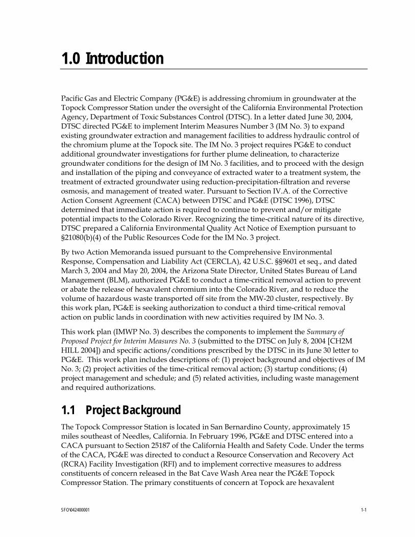
1.0 Introduction
Pacific Gas and Electric Company (PG&E) is addressing chromium in groundwater at the Topock Compressor Station under the oversight of the California Environmental Protection Agency, Department of Toxic Substances Control (DTSC). In a letter dated June 30, 2004, DTSC directed PG&E to implement Interim Measures Number 3 (IM No. 3) to expand existing groundwater extraction and management facilities to address hydraulic control of the chromium plume at the Topock site. The IM No. 3 project requires PG&E to conduct additional groundwater investigations for further plume delineation, to characterize groundwater conditions for the design of IM No. 3 facilities, and to proceed with the design and installation of the piping and conveyance of extracted water to a treatment system, the treatment of extracted groundwater using reduction-precipitation-filtration and reverse osmosis, and management of treated water. Pursuant to Section IV.A. of the Corrective Action Consent Agreement (CACA) between DTSC and PG&E (DTSC 1996), DTSC determined that immediate action is required to continue to prevent and/or mitigate potential impacts to the Colorado River. Recognizing the time-critical nature of its directive, DTSC prepared a California Environmental Quality Act Notice of Exemption pursuant to §21080(b)(4) of the Public Resources Code for the IM No. 3 project.
By two Action Memoranda issued pursuant to the Comprehensive Environmental Response, Compensation and Liability Act (CERCLA), 42 U.S.C. §§9601 et seq., and dated March 3, 2004 and May 20, 2004, the Arizona State Director, United States Bureau of Land Management (BLM), authorized PG&E to conduct a time-critical removal action to prevent or abate the release of hexavalent chromium into the Colorado River, and to reduce the volume of hazardous waste transported off site from the MW-20 cluster, respectively. By this work plan, PG&E is seeking authorization to conduct a third time-critical removal action on public lands in coordination with new activities required by IM No. 3.
This work plan (IMWP No. 3) describes the components to implement the Summary of Proposed Project for Interim Measures No. 3 (submitted to the DTSC on July 8, 2004 [CH2M HILL 2004]) and specific actions/conditions prescribed by the DTSC in its June 30 letter to PG&E. This work plan includes descriptions of: (1) project background and objectives of IM No. 3; (2) project activities of the time-critical removal action; (3) startup conditions; (4) project management and schedule; and (5) related activities, including waste management and required authorizations.
1.1 Project Background The Topock Compressor Station is located in San Bernardino County, approximately 15 miles southeast of Needles, California. In February 1996, PG&E and DTSC entered into a CACA pursuant to Section 25187 of the California Health and Safety Code. Under the terms of the CACA, PG&E was directed to conduct a Resource Conservation and Recovery Act (RCRA) Facility Investigation (RFI) and to implement corrective measures to address constituents of concern released in the Bat Cave Wash Area near the PG&E Topock Compressor Station. The primary constituents of concern at Topock are hexavalent

1.0 INTRODUCTION
SFO\042400001 1-2
chromium [Cr(VI)] and total chromium [Cr(T)]. The source was Cr(VI) salts used historically as a corrosion inhibitor in the station’s cooling towers. DTSC is the lead administering agency for the project.
PG&E is currently proceeding with the corrective measures process by which a long-term remedy for the site will be selected under State law. PG&E submitted the Corrective Measures Study (CMS) work plan in December 2002, pursuant to the RCRA corrective action process and in accordance with the DTSC CACA. The DTSC approved the CMS work plan in June 2003. PG&E and the Department of the Interior anticipate entering into an agreement by which PG&E will perform a remedial investigation and feasibility study (RI/FS) pursuant to CERCLA that is integrated fully with the State-directed CMS process.
Beginning in August 2003, DTSC and PG&E began working in a collaborative process with affected and interested agencies through the Topock Consultative Work Group (CWG), constituted under California’s site designation process. CWG members include:
• DTSC. • Colorado River Basin Regional Water Quality Control Board (CRBRWQCB). • United States Fish and Wildlife Service. • BLM. • Representatives from local Indian Tribes. • United States Bureau of Reclamation. • Metropolitan Water District of Southern California (MWD). • United States Geological Survey.
Concurrently with the CMS, and in compliance with the DTSC directive of February 9, 2004 (to implement actions referred to as Interim Measures No. 2), PG&E commenced pumping, transport, and disposal of groundwater from existing wells at the MW-20 cluster. The Interim Measures No. 2 (IM No. 2) is part of the overall corrective measures process for the site. It is a step in establishing a long-term approach for site remediation. The interim measures, proposed additional measures, and the results of the groundwater investigation will be integrated into the long-term corrective measure for the site.
DTSC has determined that the objective of the interim measures is defined as follows:
Initiate hydraulic control of the plume boundaries near the Colorado River to achieve a net reversal of gradient away from the Colorado River.
In March, PG&E began extracting groundwater at the MW-20 bench location, on property owned by the United States Bureau of Reclamation and managed by the BLM. At the direction of DTSC and upon approval of BLM, PG&E installed two extraction wells on the MW-20 bench and is currently pumping at rate of approximately 30 gallons per minute from this location (Well TW-2D).
These measures have contributed to the prevention of groundwater containing chromium from reaching the Colorado River. However, due to the influence of the Colorado River stage on groundwater levels (as described below), extracting groundwater at higher rates is likely to be needed to maintain the stated goal of hydraulic control.

1.0 INTRODUCTION
SFO\042400001 1-3
The daily fluctuations in river stage cause the surface water-groundwater interaction at this site to be dynamic. As the river levels begin to decline, the pumping rate must increase to overcome the natural tendency of the groundwater to flow toward the river. Space limitations and constraints on treatment and disposal alternatives make necessary the installation of additional facilities to extract, treat, and manage the significantly higher groundwater flows required to maintain hydraulic control of the plume near the Colorado River. Treatment facilities will be built on MWD property (San Bernardino County Assessor’s Parcel No. 650-151-06), which PG&E is in the final stages of purchasing from MWD. (MWD is providing PG&E with access to undertake required work in the property prior to the formal transfer of title of the property.)
1.2 Description of the Interim Measure No. 3 In accordance with the IM No. 3 directive from DTSC dated June 30, 2004, PG&E needs to move forward on an expedited basis with the design and installation of the following IM No. 3 project components:
• Installation and operation of new extraction wells and associated pipelines;
• Construction and operation of a new treatment facility on Parcel 650-151-06 (hereinafter the “PG&E treatment facility”);
• Installation of pipelines for conveyance of extracted groundwater from the MW-20 bench to the PG&E treatment facility, and for conveyance of treated water products (reverse osmosis [RO] brine, and potentially, treated water) back to the MW-20 bench;
• Installation of injection wells and observation wells on Parcel 650-151-06 for the disposal of the treated water, and pipelines for conveyance of treated water to the injection well fields;
• Potential installation of a direct discharge pipeline that would convey treated water to the Colorado River;
• Potential trucking and/or installation of a pipeline that would convey treated water for reuse in the cooling towers, and/or brine for disposal in the existing evaporation ponds, at the PG&E Compressor Station;
• Improvement/grading of existing access roads; and
• Other activities including the installation of additional monitoring wells to further delineate chromium in groundwater, and additional data collection to support evaluation of remedial technologies, including in-situ treatment or a slurry wall.
PG&E is designing all project facilities to avoid or minimize impacts to cultural and natural resources. PG&E has surveyed the site and conducted resource-related evaluations. A Cultural Resource Investigations Report has been submitted for review and approval by the BLM and the State Historic Preservation Office, pursuant to the National Historic Preservation Act Section 106 consultation process. Also, a Biological Resource Investigations Report has been submitted for review by BLM for consultation with the U.S. Fish and Wildlife Service and California Department of Fish and Game.

1.0 INTRODUCTION
SFO\042400001 1-4
1.3 Description of Time Critical Removal Action No. 3 PG&E has requested that BLM issue an Action Memorandum No. 3 that will cover the new activities required by DTSC (Latham and Watkins 2004); the aspects of the project insofar as they affect BLM lands will be the subject of a new Action Memorandum. PG&E is working in parallel with the DTSC to obtain approvals to construct the treatment and water management facilities on Parcel 650-151-06.
PG&E proposes to undertake the following activities on BLM land under Action Memorandum No. 3:
• Installation of influent piping and electrical conduit for the conveyance of groundwater from the MW-20 bench to the PG&E treatment facility;
• Installation of effluent piping for the conveyance of RO brine wastewater from the PG&E treatment facility back to the MW-20 bench; effluent piping would also be used for the conveyance of treated water back to the MW-20 bench for disposal by trucking, until alternative disposal methods are permitted and in place;
• Installation of piping for the conveyance of treated water over BLM-managed land from the PG&E treatment facility to proposed injection wells on Parcel 650-151-06;
• Improvements/grading of existing access roads on BLM-managed land;
• Potential installation of monitoring wells on BLM-managed land near Parcel 650-151-06 to support the evaluation of treated water disposal by injection;
• Expansion of the existing facilities on the MW-20 bench to accommodate the storage for trucking of RO brine (and potentially treated water) from the PG&E treatment facility; and
• Transportation by truck of RO brine and/or treated water from the MW-20 bench to the PG&E Topock Compressor Station, a licensed waste disposal facility, or other appropriate facility.
These components are described in more detail in Section 2. For clarity, the discussion of activities for each component has been arranged as follows: (1) a description of activities already authorized under a previous Action Memorandum, (2) a description of the activities for which PG&E is seeking authorization under Action Memorandum No. 3, and (3) a description of potential future activities in support of IM No. 3 that will require authorization under a future Action Memorandum.
SFO\042400001 2-1
2.0 Project Activities – Request for Authorization
2.1 Drilling and Investigation Activities 2.1.1 Previously Authorized Activities The IM No. 3 project will include drilling and well installation on BLM-managed property. Activities include the installation of new extraction wells to support the existing pumping operations, and monitoring wells for further characterization of chromium concentrations in groundwater. BLM has authorized this activity under a previous Action Memorandum, dated March 3, 2004. The siting, installation and pumping of these potential wells will be subject to review and approval by BLM, USFWS, and DTSC.
Currently, one existing extraction well (TW-2D) is being pumped to extract contaminated groundwater. Two wells (of the seven additional well locations previously authorized by Action Memorandum) are planned initially to supplement pumping from extraction well TW-2D. Both of these wells (PE-1 and PE-2) are in the western portion of the site (Figure 1).
The proposed well installations would result in negligible impacts to the surface environment. Submersible pumps would be placed down-hole, and subsurface concrete vaults equipped with instrumentation, valves, and other pipe appurtenances would complete the well head construction. Underground piping and electrical conduits would be connected to the well heads to convey water and provide power.
Groundwater monitoring wells on BLM-managed property to be installed for further characterization of chromium concentrations in groundwater are not addressed in this work plan as BLM has authorized this activity by previous Action Memorandum.
2.1.2 Activities Requiring Authorization under Time Critical Action Memorandum No. 3
Other drilling, well installation, and testing activities on BLM-managed property to be conducted as part of the IM No. 3 and subject to a new Action Memorandum are described below.
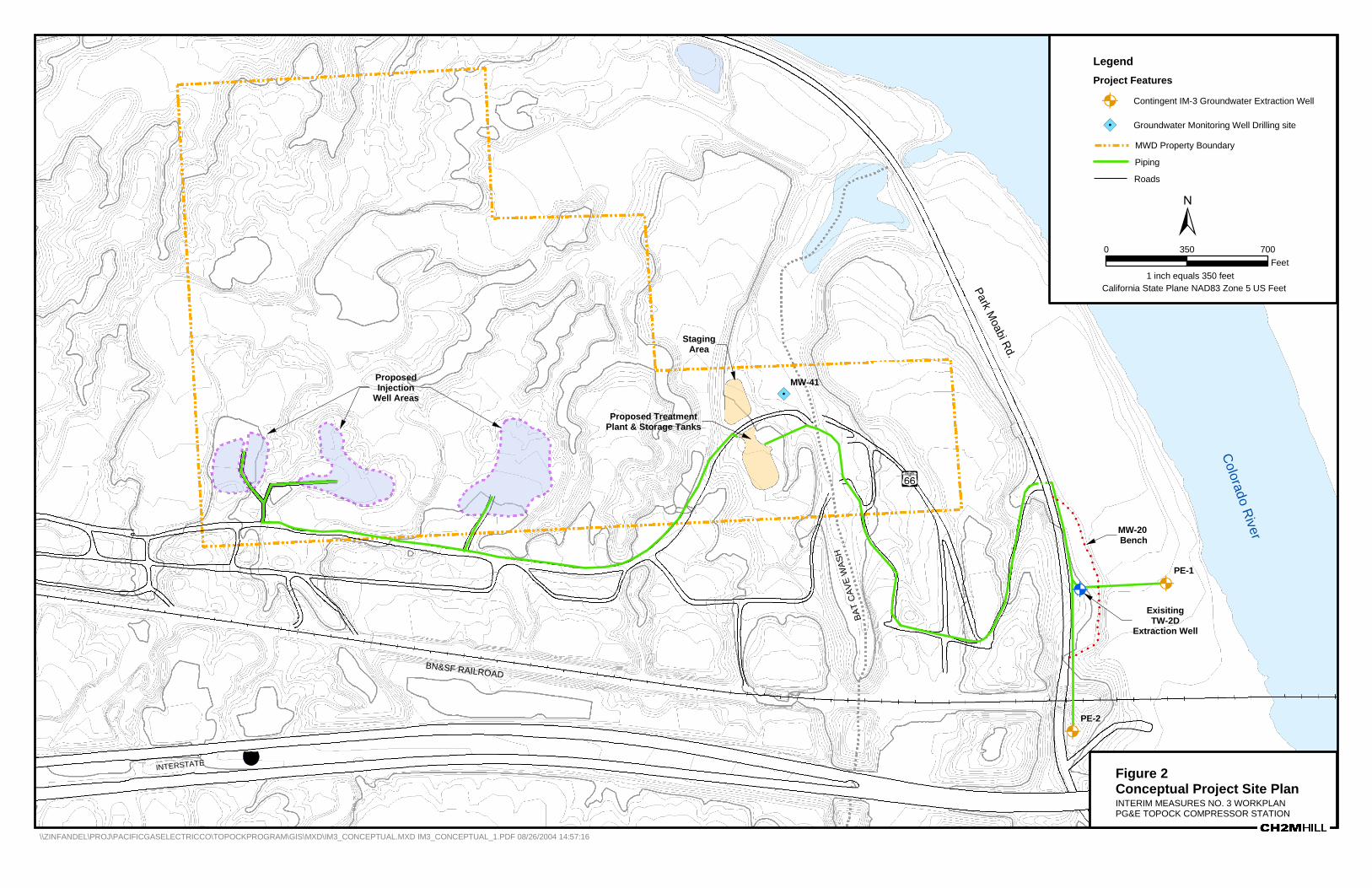
At the direction of DTSC, PG&E submitted a separate work plan on July 19, 2004 to summarize the drilling activities on Parcel 650-151-06 (Conceptual Work Plan for Hydrogeologic Characterization and Well Installation on Parcel 650-151-06). These field activities, in support of IM No. 3, involve drilling potential injection wells and conducting hydrogeologic testing. Data collected will be used to evaluate injection into the aquifer as a discharge option to manage the treated water. The conceptual plan includes the drilling and installation of up to ten injection wells and eight observation/monitoring well clusters (to assess water levels) to be installed on Parcel 650-151-06. The approximate locations of the injection well fields are shown in Figure 2. Because the proposed injection fields are close to
2.0 PROJECT ACTIVITIES – REQUEST FOR AUTHORIZATION
SFO\042400001 2-3
BLM property, it is possible that PG&E may be required to drill observation wells on BLM land in the vicinity of the injection well system to collect additional data and to monitor changes in water levels. DTSC may make a determination in September as to the need for additional drilling to support the siting of facilities for the IM. The siting, installation and pumping of these potential wells on BLM property will be subject to review and approval by BLM and DTSC.
2.1.3 Potential Activities to Support IM No. 3 That May Require Future Authorization
Additional sampling or characterization may be conducted, as directed by DTSC. These measures may include additional data collection to support evaluation of remedial technologies, including the potential installation of a slurry wall and/or the use of in-situ treatment techniques to augment remediation activity.
In-situ treatment techniques have the potential to enhance the effectiveness of existing and planned groundwater extraction and above-ground treatment by providing additional treatment in the subsurface. In-situ field pilot testing at existing and/or new wells on land managed by BLM will be considered by DTSC. In-situ pilot testing is proposed to obtain information for design of future supplemental remediation measures. PG&E will describe the methodology and location of the in situ pilot test wells and piping in a future work plan, and such activities will be subject to approval by DTSC and BLM for those wells located on BLM-managed land. Figure 1 shows the proposed location for the potential in-situ testing wells.
Also, in furtherance of the site conceptual model, a seismic evaluation in the floodplain may be necessary to supplement the drilling activities, and to obtain additional data to evaluate the potential feasibility of additional remediation approaches, including the potential installation of a barrier wall. DTSC has recommended that PG&E undertake a seismic refraction survey over the Colorado River, involving water-borne transducer technology, and thereby avoiding physical impacts to the floodplain. A water-borne survey could provide valuable information to complete the conceptual site model of the area beneath the river, and thereby complementing the data collected on land. It is not anticipated that the water-borne survey requires BLM authorization. However, contingent upon the results of a seismic refraction survey over the Colorado River, another investigation may be required by DTSC on the floodplain if additional geophysical and geotechnical evaluations are necessary to define the floodplain’s subsurface. This may include the installation of test borings. PG&E would describe the details of such a scope of work, if required by DTSC, in a future submittal to BLM.
2.2 Piping and Conveyance System 2.2.1 Previously Authorized Activities Conveyance pipelines connecting new extraction wells to the MW-20 bench have been authorized by previous action memoranda.

2.0 PROJECT ACTIVITIES – REQUEST FOR AUTHORIZATION
SFO\042400001 2-3
2.2.2 Activities Requiring Authorization under Time Critical Action Memorandum No. 3
The piping and conveyance system for IM No. 3 will consist of the following:
• Influent and effluent piping and electrical conduit between the MW-20 bench and the PG&E treatment facility. Influent piping will convey extracted groundwater to Parcel 650-151-06. Effluent piping will convey RO brine back to the MW-20 bench. Effluent piping will also convey treated water back to the MW-20 bench until more permanent disposal methods are permitted and in place to accommodate peak extraction rates.
• Piping to convey treated water from the PG&E treatment facility to the disposal facilities (injection well fields on Parcel 650-151-06, direct discharge to the Colorado River, or reuse at the PG&E Compressor Station).
Currently, PG&E is discussing the design and layout of the project facilities with DTSC and the CWG during on-board CWG review sessions. An on-board review process enables interested stakeholders to be involved in the early stages of an expedited design-build project while meeting the accelerated project schedule. A Draft Design Basis Report for Interim Measures Number 3 and accompanying drawings representing a 30 percent design were submitted to DTSC and members of the Topock Consultative Workgroup on July 30, 2004. Engineering design and construction planning are ongoing to meet the accelerated project schedule. The following description of conveyance pipelines is based on the current design and on-board review sessions conducted to date.
The proposed main piping and conveyance alignment for the project follows existing access roads and is designed to avoid impacts to the Topock Maze, former U.S. Highway 66 (Route 66) and other cultural sites. The proposed route is set forth in Figure 2. PG&E is designing all project facilities to avoid or minimize impacts to cultural and natural resources. PG&E has surveyed the site and conducted resource related evaluations. PG&E has drafted a Cultural Resource Investigations report for review and approval by the BLM and the State Historic Preservation Office (SHPO), pursuant to the National Historic Preservation Act Section 106 consultation process. Mitigation measures will be implemented as required by the BLM and SHPO as a result of the consultation process.
PG&E will offset the piping from existing utilities in accordance with applicable requirements and will work with the BLM, SHPO, and appropriate resource agencies to avoid cultural and natural resources.
Double wall high-density polyethylene (HDPE) piping will convey extracted groundwater to prevent releases of untreated groundwater. Piping and appurtenances will be sized to accommodate the anticipated system flow rates. Appurtenances to monitor system operations will include:
• Flow meter/totalizers to measure flow rate and cumulative flow from each extraction well;
• In-line sample ports for each extraction well; and
• Electrical or visual indication of pipe leakage within the containment piping. Visual leak indication would be facilitated by underground vaults placed at selected points along

2.0 PROJECT ACTIVITIES – REQUEST FOR AUTHORIZATION
SFO\042400001 2-3
the alignment. Electrical leak detection methods include, at a minimum, level detection sensors in the underground vaults.
Given the design, a leak or catastrophic pipe failure is not expected. In the event of any release or other event necessitating an emergency response, PG&E will notify immediately the BLM Lake Havasu Field Office and the United States Bureau of Reclamation Lower Colorado Regional Office as well as other agencies, such as the National Response Center, as required by law.
2.2.2.1 Piping between the MW-20 Bench and Parcel 650-151-06 The water conveyance system delivers (1) untreated water from the extraction wells on the MW-20 bench to the treatment facilities; and (2) RO brine and treated water from the treatment facility back to the MW-20 bench. To minimize and avoid impacts to cultural resources, a combination of subsurface and aboveground alignments are proposed.
From the MW-20 bench to the PG&E treatment facility, piping will be constructed in an excavated trench approximately 7 feet wide to accommodate manual assembly of pipeline. Upon completion of the construction, the piping alignment will be within an existing 10-foot-wide graded gravel access road with 2-foot-wide shoulders. Two subsurface influent (untreated water) pipelines and two subsurface effluent pipelines (treated water and RO brine stream) would be placed in a common trench running to and from the MW-20 bench and Parcel 650-151-06, as shown in Figure 2. The trench will be excavated from the MW-20 bench approximately 700 feet north on the east shoulder of Route 66 (Park Moabi Road). At this point, the pipes will be directionally drilled west beneath Route 66 to the existing access road, where the road starts to run in a southerly direction. By following this existing access road, the alignment of the conveyance system avoids an abandoned segment of Route 66 (old Route 66). The trench will be constructed approximately 1,700 feet on BLM land following this existing access road. The trench will cross onto Parcel 650-151-06, and will be routed to the treatment facility location. Trenching along the roadway will minimize the disturbance to the hill slopes around the MW-20 bench. Directional drilling or other similar techniques (e.g., boring and jacking) will be used to install segments of the piping to avoid impacts to cultural and natural resources.
Influent lines will be double-contained high-density polyethylene, and effluent lines will be single-contained polyvinyl chloride or high-density polyethylene. For the influent line conveying untreated groundwater, it is estimated that the inner pipe will be 4 inches in diameter and the outside pipe will be 8 inches in diameter. Electrical conduit also will be placed in the trench.
2.2.2.2 Piping between the Treatment Facility and the Injection Well Fields Piping would be installed to deliver treated water from the PG&E treatment facility to the proposed injection wells on the Parcel 650-151-06. A portion of the route for this pipeline will traverse BLM land, as shown on Figure 2. PG&E has conducted resource related evaluations for these project activities; mitigation measures will be implemented as required by the BLM and SHPO as a result of the National Historic Preservation Act Section 106 consultation process.
2.0 PROJECT ACTIVITIES – REQUEST FOR AUTHORIZATION
SFO\042400001 2-3
From the PG&E treatment facility, treated water will be pumped through a single wall pipeline, approximately 4 inches in diameter, to be directionally drilled beneath old Route 66 from the south to the north shoulder. Along the north shoulder of old Route 66, the pipe will be constructed in an aboveground alignment on BLM land to the proposed injection well fields at the west side of Parcel 650-151-06. The aboveground alignment minimizes disturbance to old Route 66.
2.2.3 Potential Activities to Support IM No. 3 That May Require Future Authorization
At the direction of DTSC, PG&E is evaluating three options to manage the treated water: injection into the aquifer on Parcel 650-151-06, discharge to the Colorado River under a National Pollutant Discharge Elimination System (NPDES) permit, and re-use of the treated water at the Topock Compressor Station. DSTC further directed PG&E to prepare applications to the Colorado River Basin Regional Water Quality Control Board (CRBRWQCB) for consideration at the Board’s September 15, 2004 meeting (applications were submitted to the CRBRWQCB on July 28, 2004). No decision has been made regarding which of these alternatives will be used; each alternative remains a potentially viable option for treated water disposal. Of the three disposal alternatives under evaluation, PG&E has performed the detailed engineering design for the injection well disposal method on the basis that it represents the alternative most likely to be permitted and constructed in time to meet the demands of anticipated future pumping in October and November of 2004. The details of piping alignment for the extraction well disposal alternative are described in the preceding section, and they are the subject of approvals requested under Action Memorandum No. 3. In the event that one of the other two options for treated water disposal is chosen instead of, or in addition to, disposal by injection, PG&E will perform the necessary engineering design to implement that option, and will seek BLM approval for activities on BLM property through a future Action Memorandum process.
2.2.3.1 Potential Piping to a River Discharge Point PG&E is evaluating piping alignments to accommodate the potential discharge of treated water into the Colorado River under a NPDES permit. Under the NPDES scenario, a pipeline would convey the treated water from the PG&E treatment facility across BLM property to the potential point of outfall, which may be directly into the Colorado River or to a drainage course within Bat Cave Wash. The alignment of any potential NPDES discharge pipeline would be determined following the decision by DTSC to implement this disposal option.
2.2.3.2 Potential Piping to the Topock Compressor Station PG&E is also evaluating the potential reuse of the treated water in the cooling towers at the PG&E Topock Compressor Station. Under this scenario, the treated water from the PG&E treatment facility would be either transported by truck or conveyed in a pipeline across both BLM-managed land and the Havasu National Wildlife Refuge (HNWR). The truck route or the alignment of any potential pipeline would be determined following the decision by DTSC to implement this disposal option.

2.0 PROJECT ACTIVITIES – REQUEST FOR AUTHORIZATION
SFO\042400001 2-3
2.3 Grading and Construction-Related Activities In support of the IM No. 3 drilling, well installation, and pipeline construction activities, PG&E will perform grading and other construction-related activities on BLM-managed land.
2.3.1 Previously Authorized Activities As described in Section 2.1.1, the installation of new extraction wells, and the trenching and piping installation associated with those wells, has been authorized under a previous Action Memorandum. Trenches from new extraction wells to the MW-20 bench will be approximately 3-feet wide and will be installed using backhoes or trenching machines.
2.3.2 Activities Requiring Authorization Under Time Critical Action Memorandum No. 3
Interim Measure No. 3 grading and construction-related activities to be authorized under Action Memorandum No. 3 include the following:
• Inspect the BLM property along which conveyance pipeline alignments or road improvements are planned to evaluate the placement of equipment and the suitability of construction methods.
• Perform grading to level ground as required for staging equipment and to provide easy access for construction vehicles (e.g., trucks, drill rigs) at the MW-20 bench and on the access roads. Temporary road crossings in areas where water has washed out roads may be constructed of materials such as soil and road base.
• Improve existing roads and create all-weather roads by filling in any washed out areas, carving/cutting as necessary to build roadway, and placing road base materials to finish the surface.
• Place temporary rip-rap to control erosion at up to four locations along portions of old Route 66, between the PG&E treatment facility and the potential injection well fields.
• Site and install temporary power supply (portable diesel-generator equipped with an auxiliary fuel tank), and auxiliary lighting.
• Trench for pipelines and electrical conduit. Trenches will be constructed with backhoes or trenching machines and will be approximately 3 feet deep and 7 feet wide.
Currently, PG&E is designing the project facilities; technical drawings and grading plans will continue to be discussed with DTSC and interested stakeholders during on-board review sessions.
2.3.3 Potential Activities to Support IM No. 3 That May Require Future Authorization
Grading and construction-related activities associated with (1) construction of an NPDES discharge pipeline across BLM property, and (2) construction of a pipeline conveyance to the PG&E Topock Compressor Station (for reuse of treated water and/or disposal of RO brine) will require authorization under a future Action Memorandum. The design and

2.0 PROJECT ACTIVITIES – REQUEST FOR AUTHORIZATION
SFO\042400001 2-3
engineering of such facilities, if required, will commence in the event that DTSC directs PG&E to proceed with those disposal alternatives.
2.4 Temporary Increased Storage of Effluent on, and Trucking From, MW-20 Bench
2.4.1 Previously Authorized Activities Activities to increase temporarily the storage capacity on the MW-20 bench, and to dispose of the additional stored water, associated with the IM No. 3 activities have not been authorized under previous Action Memoranda.
2.4.2 Activities Requiring Authorization Under Time Critical Action Memorandum No. 3
As discussed in Section 2.2.2, effluent piping will be installed to bring waste streams from the PG&E treatment facility products back to the MW-20 bench. The treatment process presently being designed (treatment to be performed on Parcel 650-151-06) is addition of ferrous chloride or ferrous sulfate to achieve chromium reduction, followed by removal through precipitation and filtration, and final polishing for total dissolved solids separation through RO. The process will produce three waste streams – RO concentrate (i.e., brine), RO permeate (i.e., treated water), and dewatered process sludge. The sludge will be stored at the PG&E treatment facility for transport and disposal to a licensed facility. The RO brine and treated water will be piped back to the MW-20 bench for temporary storage before being transported to an off-site facility by truck. When adequate disposal methods (injection, discharge into the river, or reuse at the PG&E Topock Compressor Station) are permitted and in place to accommodate expected peak extraction rates, PG&E will reduce or discontinue the conveyance of treated water to the MW-20 bench.
With a peak expected groundwater extraction rate of 135 gallons per minute (gpm), contingency storage of treated water and RO brine may be necessary. During the peak flow, a total of twelve or thirteen holding tanks (of 17,500-gallon capacity each) would be needed on the MW-20 bench to provide sufficient holding capacity for the RO brine and the treated water from the PG&E treatment facility. Assuming that 3 of the existing treated water tanks on the MW-20 bench are available for such use, 9 to 10 additional holding tanks may need to be added to the existing facilities. The existing operations would be expanded to accommodate the additional tanks within a lined containment area, although full secondary containment will not be necessary (the RO brine and the treated water will be nonhazardous). Approximately 25 percent of the holding capacity will be used for the RO brine, and approximately 75 percent of the holding capacity will be used for the treated water. Once a sufficient water management/on-site disposal option is in place, the extra tanks will be decommissioned and removed from the bench.
At peak groundwater extraction, up to 42 truck loads per day would be required. The site’s comprehensive transportation plan will be updated to address the increase in truck traffic along Park Moabi Road. The transportation plan would include measures to protect the roadway where needed, and to limit the effects of project traffic to designated areas.
2.0 PROJECT ACTIVITIES – REQUEST FOR AUTHORIZATION
SFO\042400001 2-3
Site operators at the MW-20 bench will continue to be responsible for daily trucking operation. The facility operational procedures will be updated to address the expanded operations. Each operator will be trained on proper operation of system equipment, field instruments, and monitoring equipment, and will be familiar with the normal operating ranges of system components. The pumping and storage system will be equipped with automatic shutoffs to prevent tank overflow and pipe failures. The automatic shutoffs combined with site inspection will provide operational reliability and safety.
Site security is provided to safeguard against vandalism and injury. During implementation of this IM, appropriate security measures will be implemented for the express purpose of providing safety to operators and the public, consistent with current operations.
2.4.3 Potential Activities to Support IM No. 3 That May Require Future Authorization
The use of the MW-20 bench for the storage and shipping of treated water is anticipated to be a temporary measure, to be implemented following startup of the treatment facilities and until a direct disposal method (injection, NPDES discharge, reuse at the Topock Compressor Station) is implemented. As such, PG&E does not foresee a need to request future authorization to conduct such work, beyond the authorization requested to be contained within Action Memorandum No. 3.
2.5 Indemnity PG&E agrees to indemnify and hold harmless BLM, its agents, and employees from any and all claims or causes of action arising from or on account of acts or omissions of PG&E, its employees, successors, agents, contractors, subcontractors, or other persons, in carrying out activities under this Interim Measures No. 3 Work Plan. PG&E further agrees that the United States, and its agencies and employees, shall not be held as a party to any contract entered into by PG&E in carrying out activities under this Interim Measures No. 3 Work Plan.

SFO\042400001 3-1
3.0 Project Management
CH2M HILL will manage the IM No. 3 activities. The proposed project management approach is intended to:
• Ensure a direct, continuous line of communication among DTSC, the PG&E project team, and all stakeholders in the CWG.
• Facilitate effective and efficient coordination and management of the various tasks.
• Implement IM No. 3 on time and in compliance with the requirements of the DTSC.
The progress and performance of the project will be monitored through:
• Monthly performance monitoring reports.
• Regular meetings with DTSC representatives.
• Regular meetings and conference calls with the CWG.
• Meetings specially convened by DTSC to resolve project issues and concerns, as applicable.

SFO\042400001 4-1
4.0 Project Schedule
The project schedule is accelerated. In response to the Department of Interior Office of the Solicitor letter dated August 2, 2004, this Work Plan has been revised for approval to commence time-critical CERCLA removal activities under an Action Memorandum No. 3. PG&E’s ability to meet the expedited schedule is dependent upon, among other factors, BLM’s authorization of this interim measure. Upon receipt of all regulatory approvals, PG&E anticipates conducting site preparation and mobilization activities in mid-September, 2004. Construction activities are expected to be completed by early November (7 to 8 weeks duration).
SFO\042400001 5-1
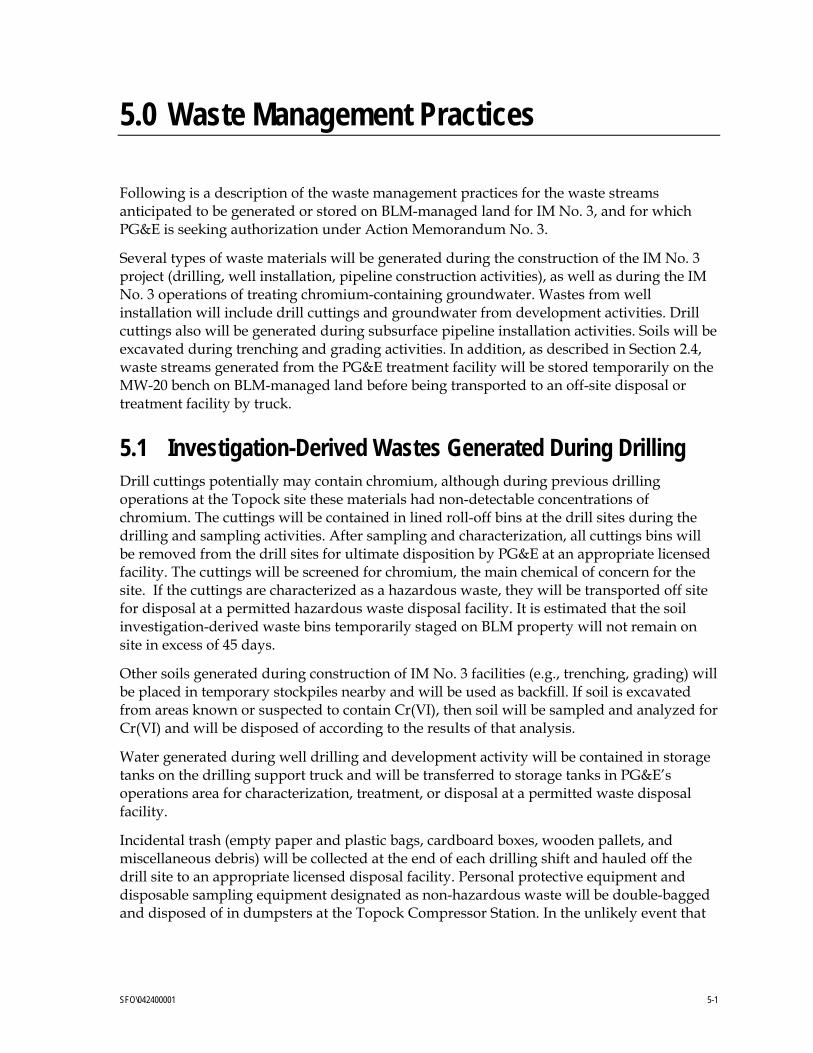
5.0 Waste Management Practices
Following is a description of the waste management practices for the waste streams anticipated to be generated or stored on BLM-managed land for IM No. 3, and for which PG&E is seeking authorization under Action Memorandum No. 3.
Several types of waste materials will be generated during the construction of the IM No. 3 project (drilling, well installation, pipeline construction activities), as well as during the IM No. 3 operations of treating chromium-containing groundwater. Wastes from well installation will include drill cuttings and groundwater from development activities. Drill cuttings also will be generated during subsurface pipeline installation activities. Soils will be excavated during trenching and grading activities. In addition, as described in Section 2.4, waste streams generated from the PG&E treatment facility will be stored temporarily on the MW-20 bench on BLM-managed land before being transported to an off-site disposal or treatment facility by truck.
5.1 Investigation-Derived Wastes Generated During Drilling Drill cuttings potentially may contain chromium, although during previous drilling operations at the Topock site these materials had non-detectable concentrations of chromium. The cuttings will be contained in lined roll-off bins at the drill sites during the drilling and sampling activities. After sampling and characterization, all cuttings bins will be removed from the drill sites for ultimate disposition by PG&E at an appropriate licensed facility. The cuttings will be screened for chromium, the main chemical of concern for the site. If the cuttings are characterized as a hazardous waste, they will be transported off site for disposal at a permitted hazardous waste disposal facility. It is estimated that the soil investigation-derived waste bins temporarily staged on BLM property will not remain on site in excess of 45 days.
Other soils generated during construction of IM No. 3 facilities (e.g., trenching, grading) will be placed in temporary stockpiles nearby and will be used as backfill. If soil is excavated from areas known or suspected to contain Cr(VI), then soil will be sampled and analyzed for Cr(VI) and will be disposed of according to the results of that analysis.
Water generated during well drilling and development activity will be contained in storage tanks on the drilling support truck and will be transferred to storage tanks in PG&E’s operations area for characterization, treatment, or disposal at a permitted waste disposal facility.
Incidental trash (empty paper and plastic bags, cardboard boxes, wooden pallets, and miscellaneous debris) will be collected at the end of each drilling shift and hauled off the drill site to an appropriate licensed disposal facility. Personal protective equipment and disposable sampling equipment designated as non-hazardous waste will be double-bagged and disposed of in dumpsters at the Topock Compressor Station. In the unlikely event that

5.0 WASTE MANAGEMENT PRACTICES
SFO\042400001 5-2
such equipment is designated as hazardous waste, it will be disposed of at a permitted facility in compliance with all applicable regulatory requirements.
5.2 Treatment Effluent Treatment effluent, consisting of RO brine and treated water, will be conveyed to and stored on the MW-20 bench. These streams will be stored in above-ground tanks in a lined containment area.
The RO brine stream is not anticipated to be a hazardous waste under California regulations (Title 22 CCR 66261.22). The RO brine will have a total dissolved solids (TDS) concentration lower than that of seawater, and will have a near-neutral pH, typically falling into the range 5.0 to 6.5. The pH would be more neutral than that of seawater; therefore, the stream would not be hazardous by virtue of the corrosivity characteristic. The RO process will concentrate the dissolved solids, including metal constituents listed in 22 CCR 66261.22, four-fold, except for chromium, which will be reduced to below 25 µg/L. The concentration of metal constituents in the RO brine stream is expected to be at least one order of magnitude lower than the regulatory threshold for hazardous waste; several constituent concentrations are anticipated to be in the range of two or three orders of magnitude below the regulatory criteria. Sampling and analysis of the RO brine will occur initially to confirm classification of this waste, and will continue as necessary for waste characterization and disposal.
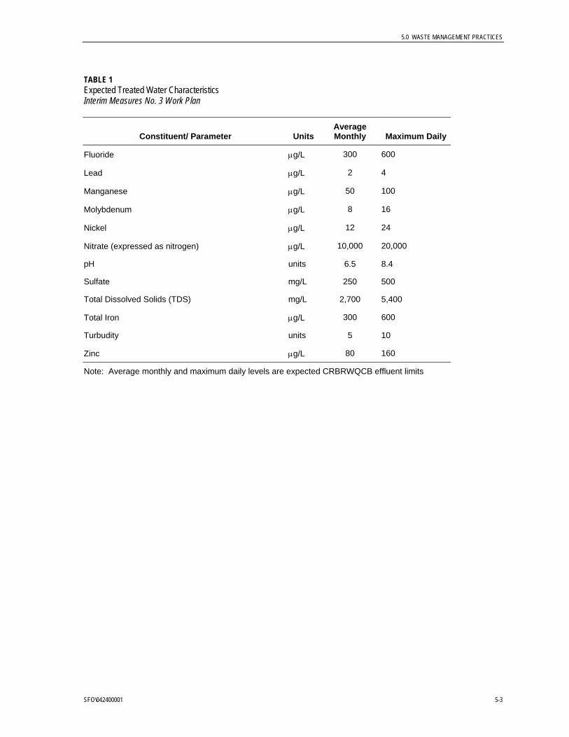
The treated water also will be non-hazardous. TDS concentrations will be reduced to below 1,000 mg/L. Common constituents, including sodium, calcium, chloride, and sulfate will be reduced by between 90 and 99.5 percent from initial concentrations in extracted groundwater. The expected characteristics of the treated water are shown in Table 1.
The RO brine and treated water will be pumped to vacuum trucks for transportation off-site to a licensed disposal or treatment facility.
TABLE 1 Expected Treated Water Characteristics Interim Measures No. 3 Work Plan
Constituent/ Parameter Units Average Monthly Maximum Daily
Aluminum µg/L 65 130
Ammonia (Ammonium) µg/L 1500 3000
Barium µg/L 100 200
Boron µg/L 1.9 3.6
Chromium (VI) µg/L 8.0 16.0
Chromium (total) µg/L 25 50
Color units 15 30
Copper µg/L 10 20
5.0 WASTE MANAGEMENT PRACTICES
SFO\042400001 5-3
TABLE 1 Expected Treated Water Characteristics Interim Measures No. 3 Work Plan
Constituent/ Parameter Units Average Monthly Maximum Daily
Fluoride µg/L 300 600
Lead µg/L 2 4
Manganese µg/L 50 100
Molybdenum µg/L 8 16
Nickel µg/L 12 24
Nitrate (expressed as nitrogen) µg/L 10,000 20,000
pH units 6.5 8.4
Sulfate mg/L 250 500
Total Dissolved Solids (TDS) mg/L 2,700 5,400
Total Iron µg/L 300 600
Turbudity units 5 10
Zinc µg/L 80 160
Note: Average monthly and maximum daily levels are expected CRBRWQCB effluent limits

SFO\042400001 6-1
6.0 Required Filings and Authorizations
The primary required filings and authorizations to implement the IM No. 3 activities are listed in the table below. This listing includes required filings and authorizations for IM No. 3 activities both on and off BLM-managed property.
Agency Filings and Authorizations
United States Bureau of Land Management Action Memorandum authorizing Interim Measures No. 3 activities on BLM land
State Water Resources Control Board (SWRCB)/Colorado River Basin Regional Water Quality Control Board (RWQCB)
Notice of Intent (NOI) and Storm Water Pollution Prevention Plan for Construction Activities (SWPPP), coverage under statewide general permit
Certified Unified Program Agency, San Bernardino County Fire Department (CUPA)
Hazardous Materials Business Plan
CUPA Conditional Authorization Notification for hazardous waste treatment
Mojave Desert Air Quality Management District (MDAQMD)
Authority to Construct (ATC) and Permit to Operate (PTO)
US Environmental Protection Agency, Region 9 (EPA)
Issuance of EPA Hazardous Waste Facility Identification Number
US Army Corps of Engineers (USACE) Federal Water Pollution Control Act (FWPCA) Section404 Permit, if required for grading of stream crossings on access road
RWQCB FWPCA Section 401 Certification
US Fish & Wildlife Service (USFWS) Endangered Species Act Section 7 Consultation
US Fish & Wildlife Service (USFWS) Authorization to install additional extraction wells and associated piping, and additional or monitoring wells
California Department of Fish and Game (CDFG)
California Fish and Game Code Section 1602 Agreement
State Historic Preservation Office (SHPO) National Historic Preservation Act Section 106 Consultation
San Bernardino County, Planning Department Grading Permits and Well Permits
San Bernardino County, Planning Department Building Permits
San Bernardino County Enterprise Permit for work within right of way of county roads
CRBRWQCB Waste Discharge Requirements (WDRs) for reuse of treated water at Topock Compressor Station
CRBRWQCB WDRs for underground injection of treated water on Parcel 650-151-06
CRBRWQCB NPDES Permit for discharge of treated water to Colorado River

SFO\042400001 7-1
7.0 Mitigation Measures
The following restrictions and controls, at minimum, related to protection of biological and cultural resources, will be complied with in implementing this IM.
1. The Mojave population of the desert tortoise is federally protected as a threatened species under the Endangered Species Act of 1973 and is protected by California law. Prohibited actions include capture, handling, harassing, collecting, injuring, or destroying animals or their burrows. Any sightings of desert tortoise must be reported immediately to the BLM Lake Havasu Field Office Wildlife Biologist.
2. All personnel are to report any sightings of desert tortoise, bighorn sheep, other wildlife species, and federally-listed migratory birds (such as bald eagle, brown pelican, etc.) to the BLM Lake Havasu Field Office, Wildlife Biologist.
3. If a desert tortoise is endangered by any activity, that activity will cease until the desert tortoise moves out of harm’s way on its own accord. A desert tortoise that needs to be handled to prevent injury or death must be handled by a certified/qualified handler only.
4. The construction zones and MW-20 bench area will be inspected at least every 4 hours during periods when the gates are open for desert tortoise that may become trapped inadvertently within the enclosure. All vehicles stationary for 15 minutes or longer will be inspected underneath for desert tortoise prior to moving. In the event that a tortoise is sited or is found under a vehicle, that tortoise will be handled only by a certified handler.
5. All native riparian species (e.g., cactus, ocotillo, mesquite, Palo Verde, etc.) will be avoided at all times. California-listed sensitive species of plants can be trimmed but not removed.
6. All construction trash and/or debris will be removed.
7. All vehicles must stay on the existing and approved routes. No vehicles are authorized to drive in the existing washes.
8. PG&E will notify immediately the BLM Lake Havasu Field Manager (or his designated representative) of any cultural resources (prehistoric/historic sites or objects) and/or paleontological resources (fossils) encountered during permitted operations and will maintain the integrity of such resources pending subsequent investigation. All operations in the immediate area of the discovery must be suspended until written authorization from BLM to proceed is issued. An evaluation of the discovery shall be made by a qualified archaeologist or paleontologist to determine appropriate actions to prevent the loss of significant cultural or scientifically-important paleontological values.
9. No permanent improvements that affect the integrity of the bridge/culvert over Bat Cave Wash on historic Route 66 will be implemented.

7.0 MITIGATION MEASURES
SFO\042400001 7-2
10. Actions that result in impacts to archaeological or historical resources are subject to the provisions of the Archaeological Resources Protection Act of 1979, as amended, and the Federal Land Policy and Management Act of 1976.
SFO\042400001 8-1
8.0 References
CH2M HILL. 2004. Summary of Proposed Project for Interim Measures No. 3. July 8.
Department of Toxic Substances Control (DTSC). 1996. Corrective Action Consent Agreement, Docket HWCA 95/96-027. February 2.
Latham and Watkins. 2004. Letter to Casey Padgett, Esq., Office of the Solicitor, U.S. Department of the Interior from Mr. David Hayes, Re: Topock. July 8.

Figures

RRB
TW-1
R-27
R-22
R-28
MW-31-60
MW-29
MW-28-25
MW-27
MW-26
MW-25
MW-23
MW-22
MW-21
MW-19
MW-13
MW-12
MW-11
MW-10
MW-09
PGE-08
PGE-07
PGE-06
MW-24B
MW-24BR
MW-34-80
MW-33-90MW-33-40
MW-32-35MW-32-20
MW-30-50
MW-30-30
MW-24A
MW-34-55PE-1
CW-1 (BLM)
HNWR
PG&E
PG&E TopockCompressor Station
BLM
BLM
MWD
HNWR
MW-20 Cluster
MW-20Bench
Approximate limits ofhexavalent chromiumin groundwater >= 0.05 mg/L(June 2004)
MW-39 cluster
MW-28-90
MW-40SMW-40D
MW-38SMW-38D
Bat
Cav
e W
ash
PE-1
Potential In-SituTesting Area
PE-2
MW-37SMW-37D
MW-35-60MW-35-135
MW-31-135
TW-2STW-2D MW-36 cluster
Figure 1Locations of Potential Interim Measures No. 3 WellsINTERIM MEASURES NO. 3 WORK PLANPG&E TOPOCK COMPRESSOR STATION
LEGEND
Potential Extraction WellLocation on BLM Property
Potential Extraction WellLocation on USFWS Property
0 150 300 450
Feet
\\ZINFANDEL\PROJ\PACIFICGASELECTRICCO\TOPOCKPROGRAM\GIS\MXD\IM3_BLM_ACTION_MEMO_WELLS.MXD IM3_BLM_ACTION_MEMO_WELLS.PDF 08/26/2004 15:04:17
Colorado R
iver
INTERSTATE
BA
T C
AV
E W
AS
H
BN&SF RAILROAD
ProposedInjection
Well Areas
Proposed TreatmentPlant & Storage Tanks
MW-20 Bench
ExisitingTW-2D
Extraction Well
StagingArea
Park M
oabi Rd.
PE-1
PE-2
MW-41
0 350 700
Feet
Legend
Project Features
Contingent IM-3 Groundwater Extraction Well
Groundwater Monitoring Well Drilling site
MWD Property Boundary
Piping
Roads
\\ZINFANDEL\PROJ\PACIFICGASELECTRICCO\TOPOCKPROGRAM\GIS\MXD\IM3_CONCEPTUAL.MXD IM3_CONCEPTUAL_1.PDF 08/26/2004 14:57:16
Figure 2Conceptual Project Site PlanINTERIM MEASURES NO. 3 WORKPLANPG&E TOPOCK COMPRESSOR STATION
1 inch equals 350 feetCalifornia State Plane NAD83 Zone 5 US Feet