Embed Size (px)
Citation preview

Application ReportSPRA777 - November 2001
1
Interfacing AC97 Codec to TMS320C5402Francis Kua TI (Singapore) CAC
ABSTRACT
This application report describes the use of TMS320C5402 DSP to interface to SigmatelSTAC9721 AC97 Codec. In the AC97 interface standard, the codec will supply a BITCLK toa digital controller for it to generate a Frame Sync (FSYNC) that is synchronized to thereceived BITCLK. The digital controller in this context is the TMS320C5402 DSP, and FSYNCis generated from the Sample Rate Generator (SRG) within the DSP. Unlike TMS320C5410,the input clock to the SRG can be selected between CPU clock and external clock (throughthe CLKS pin). C5402 does not allow the external input clock. The reason is the lack of CLKSpin. In view of this, the generated FSYNC may not be synchronized to the received BITCLK.The walk-around to this issue is to supply a common clock to both the DSP and the codec.There will be a CLKS pin multiplexed with CLKR/CLKX in Revision C silicon. The bug on theCLKIN pin of C5402 limits the maximum input clock to 1.8 V. This problem was overcome bya level shifter.
An AC97 frame format consists of one 16-bit command tag and twelve 20-bit data lots. Thiscorresponds to 256 bits/frame, and the codec has an operating sampling frequency of 48Khz. However, this codec only implements 4 out of the 12 data slots. Hence, the McBSP isprogrammed to be dual-phase, with each phase corresponding to the codec frame format.Since one data frame consists of multiple elements, the DMA is used to facilitate the datatransfer. In addition to normal data transfer, the DMA is also being used for the initializationphase.
The initial test was carried out to verify the timings between the interface. This was verifiedusing logic analyzer and digital scope. Next, the registers of the codec were written with someknown values, and a read-back operation was performed. Finally, an audio source wasinjected to the Line-In and was routed to Line-Out through the DSP. With positive results forthe above two tests, the operationally of the interface was proven to be working.
Contents
1 Introduction 2. . . . . . . . . . . . . . . . . . . . . . . . . . . . . . . . . . . . . . . . . . . . . . . . . . . . . . . . . . . . . . . . . . . . . . . . . 1.1 AC97 Frame Format 2. . . . . . . . . . . . . . . . . . . . . . . . . . . . . . . . . . . . . . . . . . . . . . . . . . . . . . . . . . . . . .
2 System Block Diagram 3. . . . . . . . . . . . . . . . . . . . . . . . . . . . . . . . . . . . . . . . . . . . . . . . . . . . . . . . . . . . . . .
3 Initialization of McBSP and DMA 4. . . . . . . . . . . . . . . . . . . . . . . . . . . . . . . . . . . . . . . . . . . . . . . . . . . . . .
4 Setting Up of Interrupt Service Routines for Data Transfer 12. . . . . . . . . . . . . . . . . . . . . . . . . . . . .
5 Flow Charts 18. . . . . . . . . . . . . . . . . . . . . . . . . . . . . . . . . . . . . . . . . . . . . . . . . . . . . . . . . . . . . . . . . . . . . . . .
6 Summary 19. . . . . . . . . . . . . . . . . . . . . . . . . . . . . . . . . . . . . . . . . . . . . . . . . . . . . . . . . . . . . . . . . . . . . . . . . . .
7 References 20. . . . . . . . . . . . . . . . . . . . . . . . . . . . . . . . . . . . . . . . . . . . . . . . . . . . . . . . . . . . . . . . . . . . . . . . .
All trademarks are the property of their respective owners.

SPRA777
2 Interfacing AC97 Codec to TMS320C5402
List of FiguresFigure 1. AC97Audio Frame 2. . . . . . . . . . . . . . . . . . . . . . . . . . . . . . . . . . . . . . . . . . . . . . . . . . . . . . . . . . . . . . . . Figure 2. System Block Diagram 3. . . . . . . . . . . . . . . . . . . . . . . . . . . . . . . . . . . . . . . . . . . . . . . . . . . . . . . . . . . . Figure 3. Transmit ISR 18. . . . . . . . . . . . . . . . . . . . . . . . . . . . . . . . . . . . . . . . . . . . . . . . . . . . . . . . . . . . . . . . . . . Figure 4. Receive ISR 19. . . . . . . . . . . . . . . . . . . . . . . . . . . . . . . . . . . . . . . . . . . . . . . . . . . . . . . . . . . . . . . . . . . .
1 IntroductionAC97 codec has been around in the market for quite some time, and it has found extensive usein the personal computer market. Until recently, many customers start to develop interests inusing this codec with TI’s DSP. This AC97 codec is designed to be controlled by a digitalcontroller. With the inclusion of the McBSP in C5402, this opens the door for TI’s DSP to controlthe codec. With the luxury of 6 channels of DMA within the DSP, this makes the data transfer ofmulti-elements from the codec to the internal memory of the DSP a much simpler task.
1.1 AC97 Frame Format
The AC-link architecture divides each audio frame into 12 outgoing and 12 incoming datastreams, each with 20-bit sample resolution. The Sigmatel STAC9271 data streams, as perAC97 specification, are as follows:
• PCM playback has two output slots with a two-channel composite PCM output stream.
• PCM record has two input slots with a two-channel composite PCM input stream.
• Control has two output slots with a Control register write port.
• Status has two input slots with a Control register read port.
• Additional data streams are defined in the AC97 specification, but their functionality are notimplemented in the Sigmatel STAC9721.
The AC97 audio frame is shown in Figure 1.
TagCMDAddr
CMDData
PCMLeft
PCMRight
Rsvd Rsvd Rsvd Rsvd Rsvd Rsvd Rsvd RsvdSDATA_OUT
SDATA_IN Tag CMDAddr
CMDData
PCMLeft
PCMRight
Rsvd Rsvd Rsvd Rsvd Rsvd Rsvd Rsvd Rsvd
SLOT
SYNC
0 1 2 3 4 5 6 7 8 9 10 11 12
Data phase = 12 slots x 20 bits = 240 bits
Tag phase = 16 bits
Figure 1. AC97Audio Frame
In reference to the connection in Figure 1, one AC97 audio frame will be transmitted andreceived at the rate of 48 KHz. This is achieved by programming the McBSP to receiveindividual word, and DMA to perform the transfer to the internal memory. Once a complete frameis received, the DMA will issue an interrupt to the DSP.

SPRA777
3 Interfacing AC97 Codec to TMS320C5402
2 System Block Diagram
The system block diagram is shown in Figure 2. From this figure, you can see that the sameoscillator drives both the DSP and Codec. However, the clock input to the C5402 is passedthrough two 1.8 V high-speed inverters. This is to provide a level shift from 3.3 V to 1.8 V. Thepurpose of level shifting is to handle the CLKIN bug of the Revision A C5402 silicon. It has beenconfirmed that Revision B silicon will have this bug fixed. Hence, the pair of inverters will not berequired. In future Revision C silicon, there will be a CLKS pin multiplexed with either CLKR orCLKX of the DSP. This will also eliminate the need of level shifters, as DSP can be clockedusing its internal oscillator while the codec continues to use external oscillator.
CLKIN
12.228 Mhz
DX
RESET
DR
FSR
FSX
CLKX
CLKR
XTL_IN
48 Khz
SDATA_OUT
SDATA_IN
SYNC
BITCLK
LINE_IN_RLINE_IN_L
LINE_OUT_RLINE_OUT_L
XF
TMS320VC5402(Revision A) Sigmatel
STAC 9721
Oscillator24.576 Mhz
LevelShifter
Figure 2. System Block Diagram
The command tag in the audio frame contains the information of the validity of the data slots.When the MSB is a 1, it indicates a valid audio frame. Otherwise, the whole frame can bediscarded. The rest of the bits in the command tag will determine whether the particular data slotis valid. When DSP is writing to the codec, all invalid slots, plus the reserved slots, must bepadded with zeroes. During initialization, the DSP must not write to the codec when it is notready. This is determined by the status of the MSB in the command tag. We can see all theseoperations being taken care of in the following routines.
In addition to these basic transfer operations, two functions are included to facilitate the user towrite and read form the registers of the codec. These functions are _codec_write and_codec_read. The user has to provide the register’s address and data to be written or readbefore calling these functions. In the routine, it will assemble a suitable AC97 transmit frame andset an UPDATE flag to 1. This will signal the DMA interrupt ISR to perform the necessaryoperation. Refer to the flow charts and the program codes.

SPRA777
4 Interfacing AC97 Codec to TMS320C5402
3 Initialization of McBSP and DMA
The McBSP has to be programmed to inter-operate with the DMA to transfer the audio frames. Itis required by the codec to pad all unused slots with zeroes. In Figure 1, there are only5 elements in the audio frame, hence we have to pad the seven unused slots with zeroes. Inorder to achieve this, the DMA is programmed as 6 elements per block, and each element is32-bit. The McBSP will TX the previous value of XSR if the DXR is not reloaded. Hence, theunused frame will be padded with zeroes. The followings are the codes that setup the system.
;*****************************************************************************
; CPU CLOCK = CLKIN*4 = 98.3Mhz
; Tx and Rx Buffer. Note that there are 6 elements in each frame and each element
; is 32 bits.
; However, the McBSP will only shift in/out the number of bits as programmed.
; Phase 1 = 16 bits, Phase 2 = 20 bits
;
; Tx and Rx buffers are defined using .long directive. However, they must be placed
; into internal RAM in the Linker Command File
;******************************************************************************
.sect “RX_AC97”
rx_buf:. long 0x00000000, 0x00000000,0x00000000, 0x00000000, 0x00000000, 0x00000000
.sect “TX_AC97”
tx_buf: .long 0x0000E000, 0x00000000,0x00000000, 0x00000000, 0x00000000, 0x00000000
;******************************************************************************
; Command Frames for the initialization phase.
; Note: Element 1 ‘s 16 LSB = CMD TAG
; Element 2 ‘s 20 LSB = CMD Addr/Status Addr
; Element 3 ‘s 20 LSB = CMD Data/Status Data
; Element 4 ‘s 20 LSB = PCM Left
; Element 5 ‘s 20 LSB = PCM Right
;******************************************************************************
.sect“CMD_BUFFER”
init: .long 0x0000E000, 0x00020000,0x00000000, 0x00000000, 0x00000000, 0x00000000
.long 0x0000E000, 0x00000000,0x00000000, 0x00000000, 0x00000000, 0x00000000
.long 0x0000E000, 0x00000000,0x00000000, 0x00000000, 0x00000000, 0x00000000
.long 0x0000E000, 0x00000000,0x00000000, 0x00000000, 0x00000000, 0x00000000
.long 0x0000E000, 0x00000000,0x00000000, 0x00000000, 0x00000000, 0x00000000

SPRA777
5 Interfacing AC97 Codec to TMS320C5402
CODEC_INIT:
RSBX XF ;RESET CODEC
STM #100,AR2 ;DELAY COUNTER
RESET1:
CALL DELAY_CLOCK ;ADD DELAY TO ENSURE CODEC IS
BANZ RESET1,*AR2– ;PROPERLY RESET
STM #00000H,IMR ;MASK ALL INTERRUPTS
STM #0FFFFH,IFR ;CLEAR ALL PENDING INTERRUPTS
STM #00010H,TCR ;STOP TIMER
STM #99,PRD ;LOAD PERIOD REGISTER
ST #_INIT_CMDS–12,*(INIT_PTR) ;
ST #INIT_LENGTH,*(INIT_STATE) ;LOAD NUMBER OF REGISTERS TO INITIALIZE
ST #0,*(INIT_FLAG) ;CLEAR INIT_FLAG
ST #_rx_buf+6,*(RX_PTR) ;
ST #_tx_buf+6,*(TX_PTR) ;
ST #0,*(CODEC_READY) ;CLEAR CODEC READY FLAG
STM #0,DXR2_0 ;CLEAR DRR
STM #0,DXR1_0 ;CLEAR DXR
ST #0,*(UPDATE) ;RESET UPDATE FLAG (FOR _write_codec function)
ST #0,*(READ_FLAG) ;RESET DATA READ FLAG (FOR _read_codec
ST #0,*(VALID_CMD_FRAME) ;
;**********************************************************************************
; Initialize PLL to CLKIN x 4
;**********************************************************************************
STM #0,CLKMD ;SET PLL TO DIV MODE
WAIT_DIV_MODE: ;
BITF *(CLKMD),#1 ;
BC WAIT_DIV_MODE,TC ;CHECK IF PLL IS IN DIV MODE
STM #37FFH,CLKMD ;SET MULTIPLIER FACTOR AND
; SWITCH TO PLL MODE
WAIT_PLL_MODE:
BITF *(CLKMD),#1 ;WAIT FOR PLL TO ACQUIRE LOCK
BC WAIT_PLL_MODE,NTC ;
SPRA777
6 Interfacing AC97 Codec to TMS320C5402
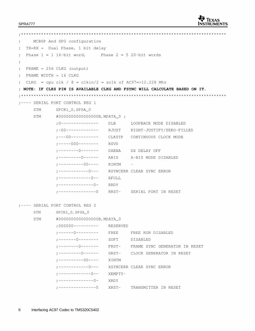
;**********************************************************************************
; MCBSP And SPG configuration
; TX=RX = Dual Phase, 1 bit delay
; Phase 1 = 1 16-bit word, Phase 2 = 5 20-bit words
;
; FRAME = 256 CLKG (output)
; FRAME WIDTH = 16 CLKG
; CLKG = cpu clk / 8 = clkin/2 = sclk of AC97=>12.228 Mhz
; NOTE: IF CLKS PIN IS AVAILABLE CLKG AND FSYNC WILL CALCULATE BASED ON IT.
;**********************************************************************************
;–––– SERIAL PORT CONTROL REG 1
STM SPCR1_0,SPSA_0
STM #0000000000000000B,MDATA_0 ;
;0~~~~~~~~~~~~~~~ DLB LOOPBACK MODE DISABLED
;~00~~~~~~~~~~~~~ RJUST RIGHT-JUSTIFY/ZERO–FILLED
;~~~00~~~~~~~~~~~ CLKSTP CONTINUOUS CLOCK MODE
;~~~~~000~~~~~~~~ RSVD
;~~~~~~~~0~~~~~~~ DXENA DX DELAY OFF
;~~~~~~~~~0~~~~~~ ABIS A-BIS MODE DISABLED
;~~~~~~~~~~00~~~~ RINTM –
;~~~~~~~~~~~~0~~~ RSYNCERR CLEAR SYNC ERROR
;~~~~~~~~~~~~~0~~ RFULL
;~~~~~~~~~~~~~~0~ RRDY
;~~~~~~~~~~~~~~~0 RRST– SERIAL PORT IN RESET
;–––– SERIAL PORT CONTROL REG 2
STM SPCR2_0,SPSA_0
STM #0000000000000000B,MDATA_0
;000000~~~~~~~~~~ RESERVED
;~~~~~~0~~~~~~~~~ FREE FREE RUN DISABLED
;~~~~~~~0~~~~~~~~ SOFT DISABLED
;~~~~~~~~0~~~~~~~ FRST– FRAME SYNC GENERATOR IN RESET
;~~~~~~~~~0~~~~~~ GRST– CLOCK GENERATOR IN RESET
;~~~~~~~~~~00~~~~ XINTM
;~~~~~~~~~~~~0~~~ XSYNCERR CLEAR SYNC ERROR
;~~~~~~~~~~~~~0~~ XEMPTY–
;~~~~~~~~~~~~~~0~ XRDY
;~~~~~~~~~~~~~~~0 XRST– TRANSMITTER IN RESET

SPRA777
7 Interfacing AC97 Codec to TMS320C5402
;–––– RX CONTROL REG 1
STM RCR1_0,SPSA_0
STM #0000000001000000B,MDATA_0
;0~~~~~~~~~~~~~~~ RESERVED
;~0000000~~~~~~~~ RFRLEN1 1 WORD PER FRAME
;~~~~~~~~010~~~~~ RWDLEN1 16-BIT WORDS
;~~~~~~~~~~~00000 RESERVED
;–––– RX CONTROL REG 2
STM RCR2_0,SPSA_0
STM #1000010001100001B,MDATA_0
;1~~~~~~~~~~~~~~~ RPHASE DUAL PHASE FRAMES
;~0000100~~~~~~~~ RFRLEN2 5 WORDS PER FRAME
;~~~~~~~~011~~~~~ RWDLEN2 N/A
;~~~~~~~~~~~00~~~ RCOMPAND NO COMPANDING
;~~~~~~~~~~~~~0~~ RFIG RECEIVE FRAME IGNORE OFF
;~~~~~~~~~~~~~~01 RDATDLY 1-BIT DELAY
;–––– TX CONTROL REG 1
STM XCR1_0,SPSA_0
STM #0000000001000000B,MDATA_0
;0~~~~~~~~~~~~~~~ RESERVED
;~0000000~~~~~~~~ XFRLEN1 1 WORD PER FRAMES
;~~~~~~~~010~~~~~ XWDLEN1 16-BIT WORDS
;~~~~~~~~~~~00000 RESERVED
;–––– TX CONTROL REG 2
STM XCR2_0,SPSA_0
STM #1000010001100001B,MDATA_0
;1~~~~~~~~~~~~~~~ XPHASE DUAL PHASE
;~0000100~~~~~~~~ XFRLEN2 5 WORDS PER FRAME
;~~~~~~~~011~~~~~ XWDLEN2 20–BIT WORD
;~~~~~~~~~~~00~~~ XCOMPAND NO COMPANDING
;~~~~~~~~~~~~~0~~ XFIG TRANSMIT FRAME IGNORE OFF
;~~~~~~~~~~~~~~01 XDATDLY 1-BIT DELAY
;–––– SAMPLE RATE GENERATOR REG 1
STM SRGR1_0,SPSA_0
STM #0000111100000111B,MDATA_0
;00001111~~~~~~~~ FWID FRAME SYNC IS 16 CYCLE WIDE
;~~~~~~~~00000111 CLKGDV CLOCK IS DIVIDED BY 8

SPRA777
8 Interfacing AC97 Codec to TMS320C5402
;–––– SAMPLE RATE GENERATOR REG 2
STM SRGR2_0,SPSA_0
STM #0011000011111111B,MDATA_0
;0~~~~~~~~~~~~~~~ GSYNC NO RE–SYNC
;~0~~~~~~~~~~~~~~ CLKSP NORMAL CLOCK EDGE POLARITY
;~~1~~~~~~~~~~~~~ CLKSM CLOCK FROM CPU SOURCE (NOR CLKS)
;~~~1~~~~~~~~~~~~ FSGM TX DUE TO SAMPLING RATE GENERATOR
;~~~~000011111111 FPER 256 CLKG CYCLE
;–––– PIN CONTROL REGISTER
STM PCR_0,SPSA_0
STM #0000010000000000B,MDATA_0
;00~~~~~~~~~~~~~~ RESERVED
;~~0~~~~~~~~~~~~~ XIOEN NO GENERAL PURPOSE I/O’S
;~~~0~~~~~~~~~~~~ RIOEN NO GENERAL PURPOSE I/O’S
;~~~~0~~~~~~~~~~~ FSXM FSX FROM INTERNAL SOURCE, FSX IS O/P
;~~~~~1~~~~~~~~~~ FSRM FSR FROM INTERNAL SOURCE, FSR IS O/P
;~~~~~~0~~~~~~~~~ CLKXM BCLKX FROM EXTERNAL SOURCE
;~~~~~~~0~~~~~~~~ CLKRM BCLKR FROM EXTERNAL SOURCE
;~~~~~~~~0~~~~~~~ RESERVED
;~~~~~~~~~0~~~~~~ CLKS_STAT
;~~~~~~~~~~0~~~~~ DX_STAT
;~~~~~~~~~~~0~~~~ DR_STAT
;~~~~~~~~~~~~0~~~ FSXP FSX IS ACTIVE HIGH
;~~~~~~~~~~~~~0~~ FSRP FSR IS ACTIVE HIGH
;~~~~~~~~~~~~~~0~ CLKXP NORMAL BCLKX POLARITY
;~~~~~~~~~~~~~~~0 CLKRP NORMAL BCLKR POLARITY ;***********************************************************************************
; DMA configuration
;
; Channel 2 for Tx , driven by tx sync (single word) event
; Channel 3 for Rx , driven by sync (single word) event
;***********************************************************************************;
; TAG | CMD ADDR | CMD DATA | PCM LEFT | PCM RIGHT |...
STM DMSRC2,DMSBAR ;SET SOURCE ADDRESS TO DRR10
STM #_ZERO_CMD,DMSBAN
SPRA777
9 Interfacing AC97 Codec to TMS320C5402
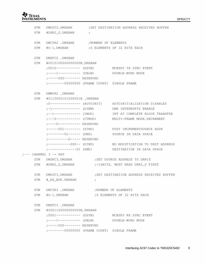
STM DMDST2,DMSBAR ;SET DESTINATION ADDRESS RECEIVED BUFFER
STM #DXR2_0,DMSBAN ;
STM DMCTR2 ,DMSBAR ;NUMBER OF ELEMENTS
STM #6–1,DMSBAN ;6 ELEMENTS OF 32 BITS EACH
STM DMSFC2 ,DMSBAR
STM #0010100000000000B,DMSBAN
;0010~~~~~~~~~~~~ (DSYN) MCBSP0 TX SYNC EVENT
;~~~~1~~~~~~~~~~~ (DBLW) DOUBLE–WORD MODE
;~~~~~000~~~~~~~~ RESERVED
;~~~~~~~~00000000 (FRAME COUNT) SINGLE FRAME
STM DMMCR2 ,DMSBAR
STM #0110000101000001B ,DMSBAN
;0~~~~~~~~~~~~~~~ (AUTOINIT) AUTOINITIALIZATION DISABLED
;~1~~~~~~~~~~~~~~ (DINM) DMA INTERRUPTS ENABLE
;~~1~~~~~~~~~~~~~ (IMOD) INT AT COMPLETE BLOCK TRANSFER
;~~~0~~~~~~~~~~~~ (CTMOD) MULTI–FRAME MODE,DECREMENT
;~~~~0~~~~~~~~~~~ RESERVED
;~~~~~001~~~~~~~~ (SIND) POST INCREMENTSOURCE ADDR
;~~~~~~~~01~~~~~~ (DMS) SOURCE IN DATA SPACE
;~~~~~~~~~~0~~~~~ RESERVED
;~~~~~~~~~~~000~~ (DIND) NO MODIFICATION TO DEST ADDRESS
;~~~~~~~~~~~~~~01 (DMD) DESTINATION IN DATA SPACE
;––– CHANNEL 3 –> RX0
STM DMSRC3,DMSBAR ;SET SOURCE ADDRESS TO DRR10
STM #DRR2_0,DMSBAN ;>16BITS, MUST READ DRR2_0 FIRST
STM DMDST3,DMSBAR ;SET DESTINATION ADDRESS RECEIVED BUFFER
STM #_RX_BUF,DMSBAN ;
STM DMCTR3 ,DMSBAR ;NUMBER OF ELEMENTS
STM #6–1,DMSBAN ;6 ELEMENTS OF 32 BITS EACH
STM DMSFC3 ,DMSBAR
STM #0001100000000000B,DMSBAN
;0001~~~~~~~~~~~~ (DSYN) MCBSP0 RX SYNC EVENT
;~~~~1~~~~~~~~~~~ (DBLW) DOUBLE–WORD MODE
;~~~~~000~~~~~~~~ RESERVED
;~~~~~~~~00000000 (FRAME COUNT) SINGLE FRAME

SPRA777
10 Interfacing AC97 Codec to TMS320C5402
STM DMMCR3 ,DMSBAR
STM #0110000001000101B ,DMSBAN
;0~~~~~~~~~~~~~~~ (AUTOINIT) AUTOINITIALIZATION DISABLED
;~1~~~~~~~~~~~~~~ (DINM) DMA INTERRUPTS ENABLE
;~~1~~~~~~~~~~~~~ (IMOD) INT AT COMPLETE BLOCK TRANSFER
;~~~0~~~~~~~~~~~~ (CTMOD) MULTI–FRAME MODE,DECREMENT
;~~~~0~~~~~~~~~~~ RESERVED
;~~~~~000~~~~~~~~ (SIND) POST INCREMENTSOURCE ADDR
;~~~~~~~~01~~~~~~ (DMS) SOURCE IN DATA SPACE
;~~~~~~~~~~0~~~~~ RESERVED
;~~~~~~~~~~~001~~ (DIND) NO MODIFICATION TO DEST ADDRESS
;~~~~~~~~~~~~~~01 (DMD) DESTINATION IN DATA SPACE
;––– ENABLE DMA ––––
STM DMSRCP,DMSBAR ;SET SOURCE PROG PAGE TO 0
STM #0H,DMSBAN ;
STM DMIDX0,DMSBAR ;SET ELEMENT ADDRESS INDEX TO +1
STM #0001H,DMSBAN ;
; ENABLE DMA
STM # 1000010001001100B ,DMPREC
;1~~~~~~~~~~~~~~~ (FREE) DMA STOPS ON EMULATION STOP
;~0~~~~~~~~~~~~~~ RESERVED
;~~0~~~~~~~~~~~~~ (DPRC[5]) CHANNEL 5 LOW PRIORITY
;~~~0~~~~~~~~~~~~ (DPRC[4]) CHANNEL 4 LOW PRIORITY
;~~~~0~~~~~~~~~~~ (DPRC[3]) CHANNEL 3 LOW PRIORITY
;~~~~~1~~~~~~~~~~ (DPRC[2]) CHANNEL 2 HIGH PRIORITY
;~~~~~~0~~~~~~~~~ (DPRC[1]) CHANNEL 1 LOW PRIORITY
;~~~~~~~0~~~~~~~~ (DPRC[0]) CHANNEL 0 LOW PRIORITY
;~~~~~~~~01~~~~~~ (INTOSEL) SINT 7==> DMA CH 2 INT
;~~~~~~~~~~0~~~~~ (DE[5]) CHANNEL 5 DISABLED
;~~~~~~~~~~~0~~~~ (DE[4]) CHANNEL 4 DISABLED
;~~~~~~~~~~~~1~~~ (DE[3]) CHANNEL 3 ENABLED
;~~~~~~~~~~~~~1~~ (DE[2]) CHANNEL 2 ENABLED
;~~~~~~~~~~~~~~0~ (DE[1]) CHANNEL 1 DISABLED
;~~~~~~~~~~~~~~~0 (DE[0]) CHANNEL 0 DISABLED

SPRA777
11 Interfacing AC97 Codec to TMS320C5402
;************************************************************************
; PULL THE RELEVANT DEVICES OUT OF RESET
;************************************************************************
STM SPCR2_0,SPSA_0 ;
LDM MDATA_0,A ;
OR #0040H,A ;PULL SAMPLE RATE GENERATOR
STLM A,MDATA_0 ;OUT OF RESET
CALL DELAY_CLOCK ;WAIT FOR 2 BIT CLOCKS
LDM MDATA_0,A ;
OR #0001H,A ;PULL TX OUT OF RESET
STLM A,MDATA_0 ;XRDY WILL TRANSIT FROM 0–>1
CALL DELAY_CLOCK ;WAIT FOR 2 BIT CLOCKS
STM SPCR1_0,SPSA_0 ;
LDM MDATA_0,A ;
OR #0001H,A ;PULL RX
STLM A,MDATA_0 ;OUT OF RESET
CALL DELAY_CLOCK ;WAIT FOR 2 BIT CLOCKS
; *********************************************************************************
; ONCE THE SAMPLE RATE GENERATOR IS ENABLED, FYNC WILL BE GENERATED AFTER SOME
; DELAYS. MEANWHILE, AFTER THE CODEC IS PULL OUT OF RESET IT WILL GENERATE BITCLK
; TO DSP AFTER A SMALL DELAY. THEREFORE, BY ADJUSTING BETWEEN THESE TWO OPERATIONS,
; WE CAN ALIGN BOTH THE FSYNC AND BITCLK TO BE SYNCHRONIZED. A DELAY MAY BE ADDED
; IF NECESSARY
; *********************************************************************************
STM SPCR2_0,SPSA_0
LDM MDATA_0,A ;
OR #0080H,A ;PULL FRAME SYNC GENERATOR
STLM A,MDATA_0 ;OUT OF RESET
;CALL DELAY_SYNC ;CALL A DELAY IF NECESSARY
STM #0029H,TCR ;LOAD TDDR AND ENABLE TIMER
STM #0E08H,IMR ;UNMASKED DMA 2, 3 AND TINT0
RSBX INTM ;ENABLE GLOBAL INT
SSBX XF ;PULL CODEC OUT OF RESET
NOP
RET ;RETURN TO CALLING PROGRAMMING

SPRA777
12 Interfacing AC97 Codec to TMS320C5402
4 Setting Up of Interrupt Service Routines for Data Transfer
Once the DMA and McBSP are properly initialized, interrupts will be generated by the DMAcontrollers every 1/48Khz interval. Hence, a suitable interrupt service routine has to be written tohandle the initialization and data transfer between codec and DSP.
The ISR and some controlling routines are as follows:
;**********************************************************************************
; DMA CHANNEL 2 INT : WHENEVER AN AC97 FRAME IS SENT
;**********************************************************************************
DMA_CH2_INT PSHM AH
PSHM AL
NOP
LD *(CODEC_READY),A ;CHECK WETHER CODEC IS READY
BC READY1,ANEQ ;IF NOT READY, SEND ZERO DATA
;AND RE–ENABLE THE DMA
;CODEC NOT READY
STM DMSRC2,DMSBAR ;SET SOURCE ADDRESS TO DRR10
STM #_ZERO_CMD,DMSBAN
STM DMDST2,DMSBAR ;SET DEST ADDR TO RECEIVED BUFFER
STM #DXR2_0,DMSBAN ;
STM DMCTR2 ,DMSBAR ;NUMBER OF ELEMENTS
STM #6–1,DMSBAN ;6 ELEMENTS OF 32 BITS EACH
ORM #4,DMPREC
B RET_TX
;CODEC IS READY
READY1: ST #0,*(CODEC_READY) ;CLEAR CODEC READY FLAG
LD *(INIT_FLAG),A ;CHECK WHETHER INITIALIZATION
BC INIT_DONE,ANEQ ;IS COMPLETED.
ADDM #12,*(INIT_PTR) ;IF YES, PROCEED TO DATA TRANSFER
LD *(INIT_STATE),A ;PHASE
SUB #1,A ;
STL A,*(INIT_STATE) ;
BC INIT_DONE1,AEQ ;
STM DMSRC2,DMSBAR ;SET SOURCE ADDRESS TO DRR10
MVDM *(INIT_PTR),DMSBAN
B INIT_DONE2 ;
INIT_DONE1: ST #1,*(INIT_FLAG) ;
SPRA777
13 Interfacing AC97 Codec to TMS320C5402
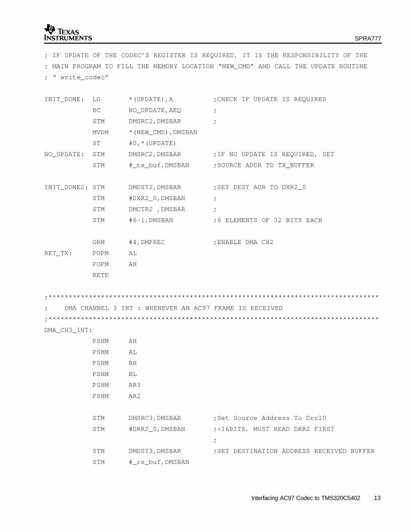
; IF UPDATE OF THE CODEC’S REGISTER IS REQUIRED, IT IS THE RESPONSIBILITY OF THE
; MAIN PROGRAM TO FILL THE MEMORY LOCATION “NEW_CMD” AND CALL THE UPDATE ROUTINE
; “ write_codec”
INIT_DONE: LD *(UPDATE),A ;CHECK IF UPDATE IS REQUIRED
BC NO_UPDATE,AEQ ;
STM DMSRC2,DMSBAR ;
MVDM *(NEW_CMD),DMSBAN
ST #0,*(UPDATE)
NO_UPDATE: STM DMSRC2,DMSBAR ;IF NO UPDATE IS REQUIRED, SET
STM #_tx_buf,DMSBAN ;SOURCE ADDR TO TX_BUFFER
INIT_DONE2: STM DMDST2,DMSBAR ;SET DEST ADR TO DXR2_0
STM #DXR2_0,DMSBAN ;
STM DMCTR2 ,DMSBAR ;
STM #6–1,DMSBAN ;6 ELEMENTS OF 32 BITS EACH
ORM #4,DMPREC ;ENABLE DMA CH2
RET_TX: POPM AL
POPM AH
RETE
;**********************************************************************************
; DMA CHANNEL 3 INT : WHENEVER AN AC97 FRAME IS RECEIVED
;**********************************************************************************
DMA_CH3_INT:
PSHM AH
PSHM AL
PSHM BH
PSHM BL
PSHM AR3
PSHM AR2
STM DMSRC3,DMSBAR ;Set Source Address To Drr10
STM #DRR2_0,DMSBAN ;>16BITS, MUST READ DRR2 FIRST
;
STM DMDST3,DMSBAR ;SET DESTINATION ADDRESS RECEIVED BUFFER
STM #_rx_buf,DMSBAN

SPRA777
14 Interfacing AC97 Codec to TMS320C5402
STM DMCTR3 ,DMSBAR ;NUMBER OF ELEMENTS
STM #6–1,DMSBAN ;6 ELEMENTS OF 32 BITS EACH
ORM #8,DMPREC ;ENABLE DMA CH3
BITF *(_rx_buf+1),#8000H ;CHECK IF CODEC IS READY
BC DMA_1,NTC ;DON’T UPDATE IF CODEC IS NOT READY
ST #1,*(CODEC_READY);
DMA_99:
LD *(INIT_FLAG),A ;
BC DMA_1,AEQ ;
;**********************************************************************************
; CHECK FOR AUTHENICATED COMMAND FRAME
;WHEN A READ-BACK OPERATION IS INITIATED BY THE MAIN PROGRAM,
;IT IS ITS RESPONSIBILITY TO INVOKE THE “_read_codec” ROUTINE.
;NEXT, THE RX ISR WILL CHECK FOR READ-BACK COMMAND FRAME
;IF A VALID COMMAND FRAME IS FOUND, IT WILL FLAG TO INDICATE IT
;THEN THE TIMER INTERRUPT WILL PERIODICALLY POLL FOR THE STATUS OF THE FLAG,
;WHEN THE TIMER ISR FOUND A VALID COMMAND FLAG, IT WILL SEND BACK THE TO THE ;MAINPROGRAM.
;**********************************************************************************
BITF *(_rx_buf+1),#6000H ; xxxxF800xxxx
BC NOT_CMD,NTC ;
RSBX SXM
NOP
STM #_rx_buf+5,AR2
nop
LD *AR2–,–4,A ; LOWER 12 BIT OF DATA
LD *AR2–,12,B ;
OR B,A ;
STL A,*(READ_DATA) ;EXTRACT DATA FROM FRAME
NOP ;
LD *AR2–,–12,A ;
LD *AR2–,4,B ;
OR B,A ;
STL A,*(READ_ADDR) ;EXTRACT REGISTER ADDR
ST #1,*(VALID_CMD_FRAME) ;SET VALID COMMAND FLAG
B DMA_1

SPRA777
15 Interfacing AC97 Codec to TMS320C5402
;**********************************************************************************
; TRANSFER DATA TO TX BUFFER
;IN THIS SETUP, INPUT FROM LINE-IN IS SENT BACK TO LINE-OUT.
;USER CAN OUTPUT HIS OWN DATA FROM ALGORITHM AT THIS SECTION
;**********************************************************************************
NOT_CMD:
MVDM *(RX_PTR),AR2 ;USER CAN OUTPUT HIS OWN PROCESSED
MVDM *(TX_PTR),AR3 ;DATA HERE
LD *AR2+,A ;
STL A,*AR3+ ;
LD *AR2+,A ;
AND #0FFF0H,A ;
STL A,*AR3+ ;
LD *AR2+,A ;
STL A,*AR3+ ;
LD *AR2+,A ;
AND #0FFF0H,A ;
STL A,*AR3+ ;
DMA_1:
POPM AR2
POPM AR3
POPM BL
POPM BH
POPM AL
POPM AH
RETE
;**********************************************************************************
; TIMER INTERRUPT TO CHECK STATUS OF THE READ BACK DATA
;**********************************************************************************
_TIMER_INT: PSHM AH
PSHM AL
PSHM ST1
RSBX SXM
LD *(READ_FLAG),A ;CHECK WHETHER IF A READ HAS BEEN
BC NO_READ,AEQ ;INITIATED
BITF *(VALID_CMD_FRAME),#1 ;CHECK IF A VALID COMMAND FRAME HAS
BC NO_READ,NTC ;BEEN RECEIVED ?

SPRA777
16 Interfacing AC97 Codec to TMS320C5402
ST #0,*(VALID_CMD_FRAME) ;IF YES, CLEAR STATUS
ST #0,*(READ_FLAG) ;
ST #1,*(DATA_READ_DONE) ;INFORM MAIN PROGRAM THAT REQUIRED
;IS COMPLETE. THEY ARE STORED IN
NO_READ: ;*(READ_DATA) AND *(READ_ADDR)
POPM ST1
POPM AL
POPM AH
RETE
;THE FOLLOWING CONTROL ROUTINES CAN BE CALLED BY
;HOST PROGRAM/APPLICATION SOFTWARE
;
;**********************************************************************************
; ROUTINE: TO DISABLE CODEC
;**********************************************************************************
_mute_codec: ST #1,*(UPDATE)
ST #_MUTE_CMD,*(NEW_CMD)
RET
;**********************************************************************************
; ROUTINE: TO ENABLE CODEC
;**********************************************************************************
_enable_codec: ST #1,*(UPDATE)
ST #_ENABLE_CMD,*(NEW_CMD)
RET
***********************************************************************************
; FUNCTION: READ FROM A PARTICULAR REGISTER OF THE AC97 CODEC
;THE MAIN PROGRAM HAS TO SUPPLY THE 7-BIT ADDRESS OF THE REGISTER
;TO BE READ TO *(_REG_ADDR_READ) BEFORE CALL THIS ROUTINE.
;THE ROUTINE WILL ASSEMBLE A WRITE COMMAND FRAME AND SET THE
;”UPDATE” FLAG FOR THE TX ISR TO PERFORM THE WRITE
;**********************************************************************************
_read_codec: ST #1,*(READ_FLAG) ;
LD *(_REG_ADDR_READ),12,A ;
STH A,*(_NEW_CMD_FRAME+2) ;UPDATE REG ADDR IN CMD ADDR SLOT
STL A,*(_NEW_CMD_FRAME+3) ;
ORM #0008H,*(_NEW_CMD_FRAME+2) ;SET WRITE BIT IN COMMAND TAG

SPRA777
17 Interfacing AC97 Codec to TMS320C5402
SUB A,A
STH A,*(_NEW_CMD_FRAME+4) ;CLEAR PCM SLOTS TO ZERO
STL A,*(_NEW_CMD_FRAME+5) ;
ST #_NEW_CMD_FRAME,*(NEW_CMD) ;TRANSFER TO NEW_CMD BUFFER
ST #0,*(VALID_CMD_FRAME) ;VALID COMMAND FLAG WILL BE SET
;BY RX_ISR ONCE IT DETECTS A CMD
;FRAME
ST #1,*(UPDATE) ;SIGNAL TX_ISR TO WRITE TO CODEC
RET
;**********************************************************************************
; FUNCTION: WRITE TO A PARTICULAR REGISTER OF THE AC97 CODEC
;MAIN PROGRAM HAS TO SUPPLY THE 7 BIT REGISTER ADDR TO BE WRITTEN TO
;AT *(_REG_ADDR_WRITE) AS WELL AS THE 16 BIT DATA TO *(_DATA_WRITE)
;BEFORE CALLING THIS ROUTINE.
;**********************************************************************************
_write_codec:
PSHM AH
PSHM AL
NOP
LD *(_REG_ADDR_WRITE),12,A ;ASSEMBLE A NEW CMD FRAME
STH A,*(_NEW_CMD_FRAME+2) ;
STL A,*(_NEW_CMD_FRAME+3) ;
ANDM #0FFF7H,*(_NEW_CMD_FRAME+2) ;
NOP
LD *(_DATA_WRITE),4,A ;
STH A,*(_NEW_CMD_FRAME+4) ;
STL A,*(_NEW_CMD_FRAME+5) ;
NOP
ST #_NEW_CMD_FRAME,*(NEW_CMD)
ST #1,*(UPDATE)
NOP
POPM AL
POPM AH
RET

SPRA777
18 Interfacing AC97 Codec to TMS320C5402
5 Flow Charts
As mentioned, the actual data transfer and re-initialization of the DMA will be carried out by theTx and Rx Interrupt Service Routines (ISR). An interrupt is generated whenever the DMAcompletes a block transfer of 1 AC97 frame. Below are the flow charts of the two routines.
Start
Is Codecready?
Re-initialize DMACH2 to send a
zero frame to thecodec. Enable
Is Codecinitialization
done?
Initialize DMA CH2’ssource address to thenext command frame.Increase initialization
status
Check if updates ofCodec’s register is
required
Initialize DMA CH2source address tonew CMD buffer
Initialize DMA CH2source address to
Tx buffer
Re-initialize DMA CH2Dest address to DXRand re-enable DMA
End
NoYes
Yes
No
No
Yes
Figure 3. Transmit ISR

SPRA777
19 Interfacing AC97 Codec to TMS320C5402
Start
Is a valid framereceived?
Re-initialize DMACH3 and
re-enable it.
Is itcommand frame?
Extract statusaddress and date.
Set Valid_Commandstatus
Transfer PCMdata to
memory
End
SetCodec_Ready
status
No
Yes
No
Yes
Figure 4. Receive ISR
Whenever a valid frame is received, the receive ISR will set the Codec_Ready flag. The flagstatus is in turn polled by a timer interrupt. Once the timer interrupt detects a change in the flagstatus, it will signal the host application that the content of the register has been read.
6 Summary
This application report has demonstrated the interface between TMS320C5402 and Sigmatel9721 AC97 codec. Direct Memory Access (DMA) and Multichannel Serial Port (McBSP) areused to initialize and perform the data transfer to and from the codec.
The lack of a CLKS pin on the TMS320C5402 was overcome by applying a common clocksource to both the DSP and the codec. With the reset of the codec controlled by the XF pin fromDSP, we can control when to enable the codec and the Frame Sync from the codec. BitCLK willonly be generated by the codec after some delay after it is pulled out of reset. There is also adelay for the FYSNC signal to be output from the SRG. Hence, this somehow will minimize thetiming jitter between these two signals. On the other hand, if CLKS pin is available, this wouldnot be an issue, as the FSYNC is derived from BitCLK through CLKS pin.

SPRA777
20 Interfacing AC97 Codec to TMS320C5402
The routines presented here are C-callable and can easily be combined with any main programsthat are written in C language. This setup was implemented on a customer product and wasshown to be working. In addition, controlling routines are included here to facilitate the control ofthe codec from the DSP. These include enabling, disabling, reading and writing controlinformation to the codec.
7 References1. TMS320C54x DSP Enhanced Peripherals Reference Set (SPRU302).
2. Sigmatel STAC9721 Data Sheet.

IMPORTANT NOTICE
Texas Instruments Incorporated and its subsidiaries (TI) reserve the right to make corrections, modifications,enhancements, improvements, and other changes to its products and services at any time and to discontinueany product or service without notice. Customers should obtain the latest relevant information before placingorders and should verify that such information is current and complete. All products are sold subject to TI’s termsand conditions of sale supplied at the time of order acknowledgment.
TI warrants performance of its hardware products to the specifications applicable at the time of sale inaccordance with TI’s standard warranty. Testing and other quality control techniques are used to the extent TIdeems necessary to support this warranty. Except where mandated by government requirements, testing of allparameters of each product is not necessarily performed.
TI assumes no liability for applications assistance or customer product design. Customers are responsible fortheir products and applications using TI components. To minimize the risks associated with customer productsand applications, customers should provide adequate design and operating safeguards.
TI does not warrant or represent that any license, either express or implied, is granted under any TI patent right,copyright, mask work right, or other TI intellectual property right relating to any combination, machine, or processin which TI products or services are used. Information published by TI regarding third–party products or servicesdoes not constitute a license from TI to use such products or services or a warranty or endorsement thereof.Use of such information may require a license from a third party under the patents or other intellectual propertyof the third party, or a license from TI under the patents or other intellectual property of TI.
Reproduction of information in TI data books or data sheets is permissible only if reproduction is withoutalteration and is accompanied by all associated warranties, conditions, limitations, and notices. Reproductionof this information with alteration is an unfair and deceptive business practice. TI is not responsible or liable forsuch altered documentation.
Resale of TI products or services with statements different from or beyond the parameters stated by TI for thatproduct or service voids all express and any implied warranties for the associated TI product or service andis an unfair and deceptive business practice. TI is not responsible or liable for any such statements.
Mailing Address:
Texas InstrumentsPost Office Box 655303Dallas, Texas 75265
Copyright 2002, Texas Instruments Incorporated