Embed Size (px)
Citation preview

Bluetooth 3.0 Single Chip for HCI Solution
Page: 1 / 18
General Description
The CW6639E is a monolithic, single-chip, stand-alone
baseband process with an integrated 2.4GHz
transceiver including EDR to 3Mbits/s for Bluetooth
v2.1+EDR and v3.0 applications. The CW6639EM is
also completely backward-compatible with Bluetooth
1.1/1.2/2.0 specification. It eliminates the need for
external flash memories and active components into the
device. Thus minimizing the footprint and system cost
of implementing a Bluetooth system.
The CW6639E has been designed in CMOS RF
technology, the most cost-performance effective silicon
process today. This use of the advanced process enables
the CW6639E to achieve the lowest cost total solution
and maintain the possible lower current consumption
in all modes of operation.
The CW6639E is the optimal solution for any voice
and/or data applications that requires the Bluetooth
SIG standard Host Controller Interface (HCI) via
either USB or UART. The CW6639E also includes
2-wire industry collaborative coexistence solution with
WLAN system interface.
Features Bluetooth specification version 3.0 compatible.
Support ACL multi-slot packets for Data/Audio
stream application.
Support SCO/eSCO link with external PCM digital
audio interface.
Support high-speed UART baud rate of up to
3Mbps
Support AFH for WiFi coexistence.
Optimal 2-wire coexistence with WLAN.
On-chip ROM eliminates dedicated flash memory
chip, significantly lowering system BOM.
Integrated 8-bit 8051 microprocessor core instead
of ARM/MIPS such high cost processors.
External Clock/Crystal 16, 26MHz system clocks
are available to apply for system requirements.
Optional external 32.768KHz crystal/clock for
deep-low power mode using.
Wide operation voltage: 2.2V~5.5V.
Package types available
CW6639E: 48pin QFN package (6mm x 6mm)
Applications Mobile and portable communication devices
PDA, PND and low-power embedded
communication devices
PC and Notebook on mother boards application
LCD Digital TV, Digital camera, Digital Photo
Frame and other high-volume consumer products
CW6639E
地址:广州市荔湾区花地大道中83号金昊大厦1808室 第1页电话:020-81775990 传真:020-81775991

Revision History
Revision Date Originator Change Description
V1.0 2013/05/27 JMC Modify it from CW6633M
V1.1 2013/05/27 YS Modify some items
CW6639E
地址:广州市荔湾区花地大道中83号金昊大厦1808室 第2页电话:020-81775990 传真:020-81775991

1. Overview
The CW6639E is Bluetooth Core Specification version 3.0 compliant and designed for used in
standard HCI (Host Control Interface) UART application. The combination of the Radio Transceiver,
BBC and the 8051-based microcontroller-BLM, BIM with on-chip ROM provide a complete lower
layer Bluetooth protocol stock including the link controller (LC), link manger (LM), and HCI
interface. The major features of CW6639E are listed in section 1.1 and the usage models-Cellular
phone is described in following section 1.2.
1.1. Features
Major features of the CW6639E include:
Fully supports Bluetooth 3.0 features
Adaptive Frequency Hopping (AFH)
Scatter Mode
QoS
eSCO
Fast Connect
LMP improvements
Synchronization
Built-in regulators
Built-in TR switch
Maximum UART baud rates of 3 Mbps
Support maximum Bluetooth data rates over HCI UART interfaces
Multipoint operation with up to 7 active slaves
HCI USB transport support with USB version 2.0 full-speed compliant interface
High speed HCI UART transport support
Channel quality driven data rate and package type selection
Extended radio and production test mode features
Full support for power saving modes
Built-in LPO clock using external 32.768KHz crystal/clock
1.2. Mobile Phone Usage Model
The CW6639E is designed to provide direct interface with new and existed cellular phone designs as
show in figure 1. The CW6639E has very flexible PCM and UART interface enabling it to
transparently connect with existing circuits. In addition, the low-cost crystal and external LPO (Low
Power Oscillator) inputs allows the use of existing features of the handset to further minimizing the
size, power and cost of the integration.
The CW6639E incorporates a number of unique features to accommodate the integration into mobile
phone platforms.
The PCM interface provides multiple modes of operation to support both master and slave as well
as interfacing to single external codec devices.
CW6639E
地址:广州市荔湾区花地大道中83号金昊大厦1808室 第3页电话:020-81775990 传真:020-81775991

The UART interface supports hardware flow control with tight integration to power control side
band signalling to support the lowest power operation.
The XTAL oscillation circuit provides a dedicated 26MHz to accommodate the typical reference
frequency used by mobile phone.
A programmable XTAL power-up or power-down signal allows the device to indicate when the
clock supplied to the CW6639E may be disabled for added power saving during sleep mode.
Both the XTAL and external LPO inputs are high impedance inputs that have minimal loading on
the driving source.
The highly linear design of the radio transceiver ensures that the device has the lowest output
spurious emissions regardless of the stat of operation and has been fully characterized in the
global cellular bands.
The transceiver design has excellent blocking (eliminating desensitization of the Bluetooth
receiver) and inter-modulation performance (distortion of the transmitted signal caused by the
mixing of the cellular and Bluetooth transmissions) in the presence of a any cellular transmission
(GSM, GPRS, CDMA, WCDMA or TD-SCDMA). Minimal external filtering is required for
integration inside the handset.
Minimal external components are required for integration and very compact packaging is
available.
CW6639E
PCM
UARTA2DP/
Headset/
Handfress
XO_P
XO_N
LXTALI
(Optional)LPO Clock
GPIOs
Figure 1 Speaker Phone Usage Model
1.3. PC/NB Usage Model
The CW6639E can be directly interfaced using the HCI USB interface and fully supports embedded
USB applications such as PC motherboard integration and Notebook, or as an external USB dongle
peripheral device.
CW6639E
地址:广州市荔湾区花地大道中83号金昊大厦1808室 第4页电话:020-81775990 传真:020-81775991
2. Functional Description
The CW6639E integrates an Bluetooth Radio Transceiver (BRT) that has been optimized for use in
2.4GHz Bluetooth wireless system and Bluetooth Baseband Core (BBC) for Bluetooth Link Control
Layer processing, Bluetooth Link Manager (BLM) for up to Blutooth HCI layer handling, Bluetooth
Interface Manager (BIM) to communicate with external host processor, GPIO block is controlled by
firmware running on the BLM/BIM for specified functions and applications, Clock Management block
for internal clock scheme and Power Management for whole system power supplying.
2.1. Bluetooth Radio Transceiver
The CW6639E has an integrated radio transceiver that has been optimized for use in 2.4GHz
Bluetooth wireless systems. It has been designed to provide low-power, low-cost, robust
communications for applications operating in the globally available 2.4GHz unlicensed ISM band. It
fully compliant with the Bluetooth Radio Specification and meets or exceeds the requirements to
provide the highest communication link quality of service. The radio completely integrated the
receiver and transmitter baluns, the antenna filter and switch together with the VCO tank on single die.
The fractional-N delta-sigma synthesizer and internal crystal calibration offer support for wide range
of external reference frequency clocks or XTAL. The digital Received Signal Strength Indicator
(RSSI) allows for efficient power control and communication. Several current saving modes are
available.
2.1.1. Transmitter Path
The CW6639E features a fully integrated zero IF transmitter. The basedband transmit data is digitally
modulated in the modulator block and up-converted to the 2.4GHZ ISM band in the transmitter path
consists of signal filtering, I/Q up-conversion, output power amplifier (PA), and RF filtering.
2.1.1.1. IQ Modulator
The transmitter features a direct IQ modulator to minimize the frequency drift during a transmit
timeslot, which results in a controlled modulation index. Digital baseband transmit circuit provides the
required spectral shaping.
2.1.1.2. Power Amplifier
The internal Power Amplifier (PA) has maximum output power of +4dBm. This allows CW6639E to
be used in class-2 and class 3 radio without an external RF PA.
2.1.2. Receiver
The receiver features a low IF scheme to down-convert the received signal for demodulation in the
digital demodulator a bit synchronizer. The receiver path provides a high degree of linearly, an
extended dynamic range, and high order on-chip channel filtering to ensure reliable operation in the
noisy 2.4GHz ISM band.
2.1.2.1. IQ Demodulator
CW6639E
地址:广州市荔湾区花地大道中83号金昊大厦1808室 第5页电话:020-81775990 传真:020-81775991

The digital IQ demodulator takes the low IF received signal an optimal frequency tracking and bit
synchronization algorithm.
2.1.2.2. Receiver Signal Strength Indicator (RSSI)
The radio portion of the CW6639E provides an RSSI signal to the baseband so that the BLM can take
part in the Bluetooth power-controlled link by providing a metric of its own receiver signal strength to
determine whether the transmitter increase or decrease it output power.
2.1.3. Synthesizer
The CW6639E features a fractional-N sigma-delta synthesizer which consists of a phase detector, a
charge pump, a loop filter, a programmable frequency divier, a voltage-controlled oscillator (VCO), a
sigma-delta modulator and a loop-up table.
2.2. Bluetooth Baseband Core
The Bluetooth Baseband Core(BBC) implements all of the timing critical functions required for high
preference Bluetooth operation. The BBC manages the buffering, segmentation and routing data for all
connections. It also buffers data that passed through it, handles data flow control, schedule ACL
TX/RX transactions, monitors Bluetooth slot usage, optimally segments and packages data into
baseband packets, manages connection status indicators and composes and decode HCI packets. The
BCC provides elementary control and processing of baseband packets. The CW6639E supports all the
ACL packet types defined in Bluetooth specification. It consists of blocks for slot timing control,
frequency hopping, encryption/decryption engine, transmitter and receiver. The ACL rate buffers are
also included here.
2.2.1. Transmitter(TX)
Transmitter contains the modules performing access code generation, HEC generation, data whitening,
FEC generation and CRC generation.
2.2.2. Receiver(RX)
Receiver provides the same functions as that of transmitter with the reverse direction.
2.2.3. Encryption/Decryption Engine
Encryption/Decryption Engine supports the maximum (128-bit) encryption key length. The effective
encryption key length that can be manufacturer/application-dependent is negotiated by the two devices
before encryption starts. Then the final encryption key is derived by the Bluetooth Link Manager
according to Bluetooth spec. The engine generates the cipher stream that is routed to both transmitter
and receiver for payload encryption and decryption.
2.2.4. Frequency Hopping Generator
Frequency Hopping Generator performs the hop frequency calculation. It supports both 23-hop and
79-hop systems, as well as the half slot hopping needed within inquiry, inquiry scan, page and page
scan states.
CW6639E
地址:广州市荔湾区花地大道中83号金昊大厦1808室 第6页电话:020-81775990 传真:020-81775991
2.2.5. Slot Timing Controller
Slot Timing Controller provides all the timing signals for the transmitter and receiver, as well as the
sync word detection.
2.2.6. Timing Recovery
Timing Recovery blocks restructures the Bluetooth data clock from the received un-processed
Bluetooth data.
2.3. Bluetooth Link Manager-8051 Microcontroller
The Bluetooth Link Manager (BLM) is an enhanced performance 8051 microcontroller and consists of
an internal register RAM, an internal data SRAM and an application program ROM. The BLM runs
software from the Link Control (LC) layer, up to the host controller interface (HCI). The BLM handles
the essential baseband processes such as link set-up, security, QoS, etc. Moreover, it also serves as a
part of the Link Controller (LC). It responds to the following jobs:
Determination of state transition
According to current status and the settings from Host, BLM decides the state transition and the usage
of next time slot.
LMP messages processing
LMP messages contain various commands concerning security such as authentication, paring,
encryption key size, etc., as well as state management like hold mode, sniff mode and park mode.
Besides, link policy commands such as channel quality-driven data rate and quality of service are also
handled by BLM. Moreover, the power control for both baseband and RF module are accomplished by
the BLM.
Link layer flow control
The BLM is responsible for ACL link flow control.
Authentication key and encryption key generation
Authentication is mandatory for a Bluetooth device. The BLM is responsible for authentication key
and encryption key generation. Certain tables for deriving these keys are necessary.
Control in test modes
In test modes, there are mainly two test items: transmitter test and loopback test. The BLM makes
additional operations on both payload and frequency hop control which do not occur in the normal
mode.
HCI packet processing
There are three types of HCI packets: command packets, event packet, and data packets. The BLM
receives the command packets from Host and makes response. Then the event packets are sent to the
Host for status report. To transmit data over the air interface, the HCI data packets need to be
segmented into baseband packets such as DM1 and DM3 accordingly. In the receiving path, these
baseband packets are reassembled to HCI data packets. The operations of segmentation and
reassembly are accomplished by BLM.
DMA channel control
DMA channels provide high-speed data transfer between several data buffers. The channels are also
under the control of BLM.
CW6639E
地址:广州市荔湾区花地大道中83号金昊大厦1808室 第7页电话:020-81775990 传真:020-81775991

2.4. Bluetooth Interface Manager-8051 Microcontroller
The Bluetooth Interface Manager (BIM) is an enhanced performance 8051 microcontroller and
consists of one UART port, one USB port, an internal register RAM, an internal data SRAM and an
application program ROM. The BIM responds for the physically transport protocol processing. For
HCI RS232, it processes the COBS if needed. As for USB, it manages the device address, monitors the
status of the transaction, and manages the FIFOs. After removing the redundant information in any
type of transport layer, the BIM moves data to a FIFO connecting to the BLM.
2.4.1. USB
The CW6639E provides a full speed Universal Serial Bus (USB) interface for communicating with
other compatible digital devices. The CW6639E acts as a USB peripheral, responding to request from
a master host controller such as a PC.
2.4.2. UART
The CW6639E provides standard 2-wire interface (TXD, RXD) UART port with adjustable baud rates
from 1200bps to 3,0Mbps by internal setting registers. The interface supports the Bluetooth 3.0 UART
HCI specification.
2.4.3. Audio PCM Interface
The Audio PCM Interface on the CW6639E can connect to linear/A-law/Mu-law PCM CODEC
devices in master or slave mode. In the master mode, the CW6639E generates the FSYN and BCLK
signals, and in salve mode, these signals are provided by another master on the PCM interface and are
inputs to the CW6639E.
2.5. GPIO Port
The CW6639E has a total of 8 General Purpose I/Os(GPIOs) GPIO0, 1, 2, 3,4 ,5, 9, 10. These are
controlled by firmware running on the device. All of I/Os are 3.3 tolerant, COMS, programmable
pull-ups.
2.6. Clock Management
The CW6639E uses two different frequency references for normal and low-power operational modes.
And external crystal or external frequency reference driven by a temperature compensated crystal
oscillator (XTAL) signal is used for the generated of all of radio frequencies and normal operating
clocking. The acceptable frequency rates are 16 or 26MHz. The XO_P and XO_N pins are used to
connect an external crystal to provide a frequency reference. Either an external 32.768KHz crystal
oscillator is connected between LXTALI and LXTALO pin or 32.768KHz clock is connected to
LXALI pin for low power mode timing. The RSTB pin is used to reset whole system of CW6639E to
initial state. The Clock Management block includes three sub-blocks for whole system clocking and
resetting: Power-On Reset block is used to completely reset all circuits to a known power on state,
Clock Divider block is used generated corresponding different system clocks for whole system using
and PLL block is used to generated higher reference clock as internal BBC and microcontrollers
system clock..
CW6639E
地址:广州市荔湾区花地大道中83号金昊大厦1808室 第8页电话:020-81775990 传真:020-81775991
2.6.1. Power-On Reset (POR)
The CW6639E has an integrated power-on reset circuit which will completely reset all circuits to a
know power on state. This action can also be driven by an external reset signal which can be used to
externally control the device, forcing it into a power-on reset state. The RSTB pin is an active low
signal and is not required to be connected in most applications. No external pull-up resistor is required.
2.6.2. Clock Divider
The Clock Divider unit is used to generate the corresponding clock frequency for each sub-system of
CW6639E. The CW6639E adopts the clock gating technical to reduce the power-consumption for
better battery life cycle in portable device. Each block of CW6639E is work well under the suitable
clock rate to prevent any extra redundancy power consumption.
2.6.3. PLL.
The PLL block is used to generate high system clock for normal operational mode using and the
external main reference clock its reference source.
2.7. Power Management
The Power Management unit has three on-chip linear regulators: UVDD LDO, VDD LDO and RVDD
LDO. The UVDD LDO regulator is dedicated to supply internal USB transceiver with 3.3V/3.0V/2.8V
and 2.5Vdc selectable output. The VDD LDO regulator supplies the whole digital core of CW6639E
with 1.8V/1.65Vdc selectable output. The RVDD LDO regulator provides 1.8Vdc output to the
internal RF circuits of CW6639E.
2.7.1. UVDD LDO
The UVDD LDO regulator is a 3.3Vdc linear regulator which can be used to power the internal USB
transceiver when USB port is adopted in the application. The UVDD pin is the output node and needs
to connect a decoupling circuit to UVSS for best performance showing. This regulator is operating
from single 3.7V to 5.5V of input supply form VBATU pin with less than 50mV of maximum dropout
voltage at full load (70mA).
2.7.2. VDD LDO
The VDD LDO regulator is a 1.8Vdc linear regulator which can be used to power the internal digital
core of CW6639E. Its corresponding grounding pin is VSS. The VDD pin is the output node of and
needs to connect a decoupling circuit to VSS for best performance showing. This regulator is operating
from single 2.2V to 5.5V of input supply form REG_IN pin with less than 50mV of maximum dropout
voltage at full load (70mA).
2.7.3. RVDD LDO
The RVDD LDO regulator is a 1.8Vdc linear regulator which can be used to power the internal RF
circuits. Its corresponding grounding pin is RVSS. The RVDD pin is the output node of and needs to
connect a decoupling circuit to RVSS for best performance showing. This regulator is operating from
single 2.2V to 5.5V of input supply form REG_IN pin with less than 50mV of maximum dropout
voltage at full load (80mA).
CW6639E
地址:广州市荔湾区花地大道中83号金昊大厦1808室 第9页电话:020-81775990 传真:020-81775991

3. Pin Assignments
1
2
3
4
5
6
7
8
9
10
11
12
36
35
34
33
32
31
30
29
28
27
26
25
13 14 15 16 17 18 19 20 21 22 23 24
48 47 46 45 44 43 42 41 40 39 38 37
BL_VI
USBDM
TXD
RXD
CTS
RTS
BCLK
E-GNDVSSIO
DR
VDDIO
CDCLK
VSS
GPIO0
GPIO1
RSTB
GPIO9
GND_ANT1
RXTX
GND_ANT1
USBDP
GPIO5
E-GND
GPIO4
GPIO3
VDDQ
E-GND
GPIO10
LXTALI
TEST_EN
VSS
VDD
XO_P
CW6639ELQFP48
VCC_RFVDD
VCC_IF_XO
PLL_OUT
VTUNE
LXTALO
RVDD
CNR
XO_N
DT
GPIO2
VCC_VCO
FSYN
REG_IN
N/C
Figure 2: CW6639E 48-pin QFN6x6 Pin Diagram(Top-View)
Table 1: Pin Description
Pin Number Pin Name I/O Power
Domain Description
Clock/Crystal Interface and Reset
41 XO_P I RVDD Crystal or frequency reference input
42 XO_N O RVDD Crystal Oscillator output. Connect with XO_P if the
reference clock is supplied
1 LXTALI I IOVDD Low clock rate crystal driver input pin for 32.768KHz
crystal or external clock input. Connect to IOVSS if no
low clock is applied.
CW6639E
地址:广州市荔湾区花地大道中83号金昊大厦1808室 第10页电话:020-81775990 传真:020-81775991
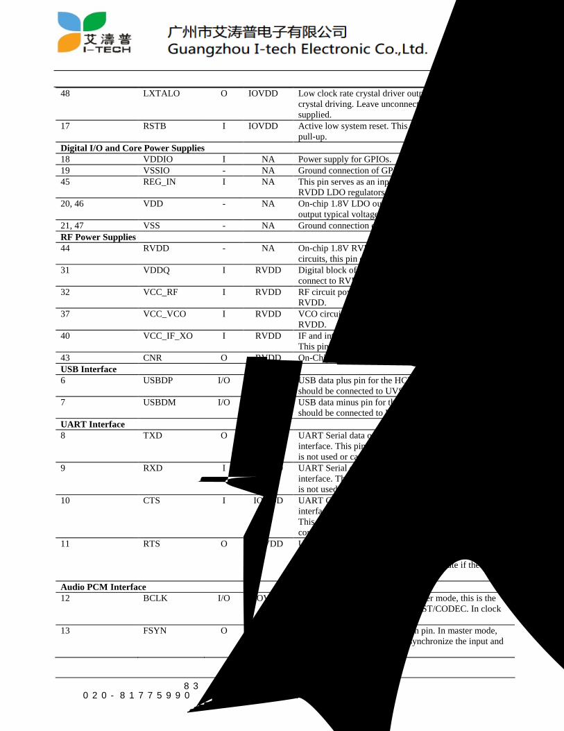
48 LXTALO O IOVDD Low clock rate crystal driver output pin for 32.768KHz
crystal driving. Leave unconnected if low clock is
supplied.
17 RSTB I IOVDD Active low system reset. This pin contains a weak
pull-up.
Digital I/O and Core Power Supplies
18 VDDIO I NA Power supply for GPIOs.
19 VSSIO - NA Ground connection of GPIOs
45 REG_IN I NA This pin serves as an input of the on-chip VDD and
RVDD LDO regulators.
20, 46 VDD - NA On-chip 1.8V LDO output for digital core, this pin
output typical voltage is 1.8V.
21, 47 VSS - NA Ground connection of on-chip 1.8 VDD LDO
RF Power Supplies
44 RVDD - NA On-chip 1.8V RVDD LDO output to supply internal RF
circuits, this pin output typical voltage is 1.8V.
31 VDDQ I RVDD Digital block of RF circuit power supply. This pin must
connect to RVDD.
32 VCC_RF I RVDD RF circuit power supply. This pin must connect to
RVDD.
37 VCC_VCO I RVDD VCO circuit power supply. This pin must connect to
RVDD.
40 VCC_IF_XO I RVDD IF and internal Crystal Oscillator circuit power supply.
This pin must connect to RVDD
43 CNR O RVDD On-Chip RVDD LDO external decoupling capacitor pin.
USB Interface
6 USBDP I/O UVDD USB data plus pin for the HCI USB interface. This pin
should be connected to UVSS if USB is not used.
7 USBDM I/O UVDD USB data minus pin for the HCI USB interface. This pin
should be connected to UVSS if USB is not used.
UART Interface
8 TXD O IOVDD UART Serial data output port for the HCI UART
interface. This pin should be left unconnected if UART
is not used or can be configured to the GPIO Pin 14.
9 RXD I IOVDD UART Serial data input port for the HCI UART
interface. This pin should be left unconnected if UART
is not used or can be configured to the GPIO Pin 15
10 CTS I IOVDD UART Clear to Send-active low for HCI UART
interface when the hardware flow control feature enable.
This pin is used to set the system clock rate if the flow
control feature is disabled.
11 RTS O IOVDD UART Request to Send-active low for HCI UART
interface when the hardware flow control feature enable.
This pin is used to set the system clock rate if the flow
control feature is disabled.
Audio PCM Interface
12 BCLK I/O IOVDD PCM serial data clock pin. In master mode, this is the
clock output into the external HOST/CODEC. In clock
slave mode, this is an input pin.
13 FSYN O IOVDD PCM serial data synchronization pin. In master mode,
this is an 8Khz sync signal to synchronize the input and
output serial data streams.
CW6639E
地址:广州市荔湾区花地大道中83号金昊大厦1808室 第11页电话:020-81775990 传真:020-81775991

14 DT O IOVDD PCM serial data output pin. This data is clocked with
BLCK, and first serial bit is synchronized by FSYN
15 DR I IOVDD PCM serial data input pin. This data is clocked with
BLCK, and first serial bit is synchronized by FSYN
16 CDCLK O IOVDD External CODEC system clock. It can enable/disable to
output the system clock to drive an external CODEC.
GPIO
22, 23, 24, 25, 26,
27, 28, 29
GPIO0~GPIO
10
I/O IOVDD 3.3V tolerant GPIO pin with programmable pull-up.
Radio
33, 35 GND_ANT1 - RVDD Ground connection of RF I/O antenna. These pins must
connect to RVSS.
34 RXTX - RVDD RF I/O antenna pin.
38 VTUNE I RVDD VCO tune input pin.
39 PLL_OUT O RVDD Charge Pump output
Battery-Low Detector
2 BL_VI I VDD The input detection pin of Battery-Low Detector
Reserved Pins
30 TEST_EN I IOVDD The test mode enable pin. This pin should be left
unconnected for field application.
GND
4,5,36 E-GND - NA GND
4. Electrical Characteristics
4.1. Absolute Maximum Ratings
Table 2: Maximum Electrical Rating
Rating Minimum Maximum Unit Storage temperature -40 +150
oC
Supply voltage of REG_IN -0.4 5.5 V
Supply voltage of VBATU -0.4 5.5 V
Supply voltage of UVDD -0.4 4.0 V
Supply voltage of IOVDD -0.4 4.0 V
Supply voltage of input/output Pin IOVSS-0.4 IOVDD+0.4 V
Supply voltage of VDD -0.4 3.0 V
Supply voltage of RVDD, VCC_RF, VCC_IF_VCO,
VCC_XO
-0.4 3.0 V
4.2. Recommended Operating Conditions
Table 3: Recommended Operating Conditions
Rating Minimum Typical Maximum Operation temperature 0
oC +25
oC +70
oC
Supply voltage of REG_IN 2.2V 3.3V 5.5V
Supply voltage of VBATU 3.7V 5.0V 5.5V
Supply voltage of UVDD 2.8V 3.3V 3.6V
Supply voltage of IOVDD 1.7V 3.3V 3.6V
Supply voltage of VDD 1.7V 1.8V 2.0V
CW6639E
地址:广州市荔湾区花地大道中83号金昊大厦1808室 第12页电话:020-81775990 传真:020-81775991

/
Supply voltage of RVDD, VCC_RF, VCC_IF_VCO,
VCC_XO
1.7V 1.8V 2.0V
4.3. Clocks
Table 4: Signal Specification of XO_P/XO_N Pin
Crystal Oscillator Minimum Typical Maximum Crystal frequency - 26MHz -
Crystal load capacitance 8pF 10pF 12pF
Frequency tolerance ±20ppm
Digital trim range 0pF - 3.1pF
Digital trim step - 100fF -
External clock of XO_P1 Minimum Typical Maximum
Input frequency - 26MHz -
Clock input level 0.8Vp-p - RVDD
XO_P input impedance 100KΩ - -
XO_P input impedance - - 4pF
1. Connect XO_N and XO_P together when use external reference clock instead of crystal.
Table 5: Signal Specification of LXTALI/LXTALO Pin
Crystal Oscillator Minimum Typical Maximum Crystal frequency - 32.768KHz -
Crystal load capacitance - 20pF -
Frequency tolerance ±200ppm
External clock of LXTALI1 Minimum Typical Maximum
Input frequency - 32.768KHz -
Clock input level 0.8 x VDD - -
LXTALI input impedance 100KΩ - -
1. Leave LXTALO unconnected when use external reference clock instead of crystal.
4.4. Linear Regulator
Table 6: UVDD LDO
UVDD Liner Regulator Minimum Typical Maximum Input voltage 3.7V - 5.5V
Dropout voltage (Iload=70mA) - - 0.2V
Output voltage (Iload=70mA) - 3.3V -
Temperature coefficient - - -
Output noise - - -
Load regulation (Iload<70mA) - - 200mV/A
Maximum output current - - 70mA
Quiescent current - 7uA -
Table 7: VDD LDO
VDD Liner Regulator Minimum Typical Maximum Input voltage 2.2V - 5.5V
Dropout voltage (Iload=70mA) - - 0.2V
CW6639E
地址:广州市荔湾区花地大道中83号金昊大厦1808室 第13页电话:020-81775990 传真:020-81775991

Output voltage (Iload=70mA) - 1.8V -
Temperature coefficient - - -
Output noise - - -
Load regulation (Iload<70mA) - - 200mV/A
Maximum output current - - 70mA
Quiescent current - 7uA -
Table 8: RVDD LDO
RVDD Liner Regulator Minimum Typical Maximum Input voltage 2.2V - 5.5V
Dropout voltage (Iload=70mA) - - 0.2V
Output voltage (Iload=70mA) - 1.8V -
Temperature coefficient - - -
Output noise - - -
Load regulation (Iload<70mA) - - 200mV/A
Maximum output current - - 80mA
Quiescent current - 20uA -
4.5. Power Consumption
Table 9 shows the current consumption for (IOVDD/REG_IN=2.8V, RVDD=1.8V, VDD=1.8V)
(TA=25oC) (XO_P=26MHz, LXTALI=GND) (UART HCI=921.6Kbps)
Table 9: Typical Current Consumption
Operational Mode Minimum Typical Maximum
Page scan, time internal 1.28s - 1mA -
Inquiry - 55mA -
Page scan and Inquiry - 1.6mA -
ACL no traffic - 26mA -
ACL with file transfer - 47mA -
SCO HV3 - 52mA -
Sleep - 80uA -
4.6. RF Specifications
Table 10: Receiver RF specifications
Parameter Minimum Typical2 Maximum
Receiver Selection
Frequency range 2402MHz - 2480MHz
Rx sensitivity1 GFSK, 0.1% BER -88dBm -86dBm -84dBm
π/4-DQPSK, 0.01% BER - -86dBm -
8-DPSK, 0.01% BER - -78dBm -
Input IP3 -21dBm - -
Maximum input GFSK, 0.1% BER - 0dBm -
π/4-DQPSK, 0.1% BER - 0dBm -
CW6639E
地址:广州市荔湾区花地大道中83号金昊大厦1808室 第14页电话:020-81775990 传真:020-81775991
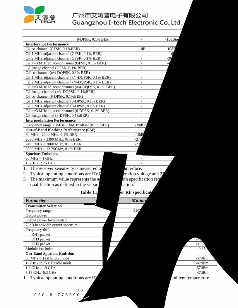
8-DPSK, 0.1% BER - -10dBm -
Interference Performance
C/I co-channel (GFSK, 0.1%BER) 11dB 10dB -
C/I 1 MHz adjacent channel (GFSK, 0.1% BER) - -1dB 0dB
C/I 2 MHz adjacent channel (GFSK, 0.1% BER) - -36dB -30dB
C/I >=3 MHz adjacent channel (GFSK, 0.1% BER) - -43dB -40dB
C/I Image channel (GFSK, 0.1% BER) - -15dB -9dB
C/I co-channel (π/4-DQPSK, 0.1% BER) - 12dB 13dB
C/I 1 MHz adjacent channel (π/4-DQPSK, 0.1% BER) - -7dB 0dB
C/I 2 MHz adjacent channel (π/4-DQPSK, 0.1% BER) - -32dB -30dB
C/I >=3 MHz adjacent channel (π/4-DQPSK, 0.1% BER) - -43dB -40dB
C/I Image channel (π/4-DQPSK, 0.1%BER) - -19dB -7dB
C/I co-channel (8-DPSK, 0.1%BER) - 20dB 21dB
C/I 1 MHz adjacent channel (8-DPSK, 0.1% BER) - 0dB 5dB
C/I 2 MHz adjacent channel (8-DPSK, 0.1% BER) - -27dB -25dB
C/I >=3 MHz adjacent channel (8-DPSK, 0.1% BER) - -35dB -33dB
C/I Image channel (8-DPSK, 0.1%BER) - -13dB 0dB
Intermodulation Performance
Frequency range +3MHz~+6MHz offset (0.1% BER) -39dBm - -
Out-of-Band Blocking Performance (CW)
30 MHz - 2000 MHz, 0.1% BER -10dBm -3dBm -
2000 MHz – 2399 MHz, 01% BER -27dBm -13dBm -
2498 MHz – 3000 MHz, 0.1% BER -27dBm -14dBm -
3000 MHz – 12.75GMz, 0.1% BER -10dBm -6dBm -
Spurious Emissions
30 MHz – 1 GHz - - -
1 GHz -12.75 GHz - - -
1. The receiver sensitivity is measured on the device interface.
2. Typical operating conditions are RVDD=1.8V operation voltage and 25οC ambient temperature.
3. The maximum value represents the actual Bluetooth specification required for Bluetooth
qualification as defined in the version 3.0 specification.
Table 11: Transmitter RF specifications
Parameter Minimum Typical1 Maximum
Transmitter Selection
Frequency range 2402MHz - 2480MHz
Output power -3dBm +1dBm +4dBm
Output power level control 2dB 4dB 8dB
20dB bandwidth output spectrum - 780KHz 1000KHz
Frequency drift
DH1 packet - 13KHz ±25KHz
DH3 packet - 15KHz ±40KHz
DH5 packet - 15KHz ±40KHz
Modulation Index 0.28 0.32 0.35
Out-Band Spurious Emission
30 MHz – 1 GHz idle mode - - -57dBm
1 GHz -12.75 GHz idle mode - - -47dBm
1.8 GHz - 1.9 GHz - - -57dBm
5.15 GHz -5.3 GHz - - -47dBm
1. Typical operating conditions are RVDD=1.8V operation voltage and 25οC ambient temperature.
CW6639E
地址:广州市荔湾区花地大道中83号金昊大厦1808室 第15页电话:020-81775990 传真:020-81775991

2. The maximum value represents the actual Bluetooth specification required for Bluetooth
qualification as defined in the version 3.0 specification.
3. the RF characteristics are measured at the chip interface.
CW6639E
地址:广州市荔湾区花地大道中83号金昊大厦1808室 第16页电话:020-81775990 传真:020-81775991
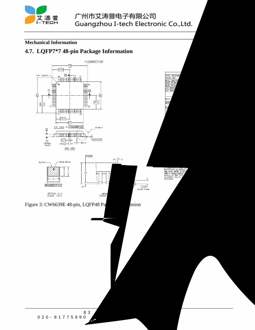
Mechanical Information
4.7. LQFP7*7 48-pin Package Information
Figure 3: CW6639E 48-pin, LQFP48 Package Dimension
CW6639E
地址:广州市荔湾区花地大道中83号金昊大厦1808室 第17页电话:020-81775990 传真:020-81775991

5. Ordering Information
Package Order Number Type Size Shipment Method
48-Pin LQFP (Pb free) 7 x 7 x 1.4-0.5mm Tape&Reel CW6639E
Minimum Order Quantity
Tape & Reel: 3Kpcs/reel
CW6639E
地址:广州市荔湾区花地大道中83号金昊大厦1808室 第18页电话:020-81775990 传真:020-81775991