Embed Size (px)
Citation preview

I/O Function Guide
Publication number 54652-97004
August 2000
© Copyright Agilent Technologies 1991-1996, 2000 All rights reserved
Interface Modules forAgilent 54600-SeriesInstruments

Contents
To install the interface module 6
Print/Utility Menu 8
To select your printer or plotter. 9To setup your printer or plotter 11To set formfeed 12To print or plot gray scale 13
Gray scale printing 13Gray scale plotting 14
To print or plot scale factors 15To set GPIB addresses 17
Instrument address 17Printer Address 17
To set RS-232 baud rate and handshake 18Baud rate 18Handshake 18
2

Introduction
These modules provide the means for remote communication withAgilent 54600-series instruments. For programming specifics, refer tothe Programmer’s Guide or Programmer’s Reference shipped withyour oscilloscope or logic analyzer. The hardcopy process does notinterrupt front-panel operation of the instrument. While any of theinterfaces are connected to the rear panel of the instrument, theinstruments trace memories become nonvolatile and are saved whenthe power is removed from the instrument.
Agilent 54650A GPIB Interface Module
• Full programmability
• Hardcopy output
Agilent 54651A RS-232-C Interface Module
• Full programmability
• Hardcopy output
Agilent 54652A Parallel Interface Module
• Hardcopy output
Agilent 54652B Parallel/RS-232-C Interface Module
• Full programmability
• Hardcopy output
• Connection to both an RS-232-C controller and a parallel printer at thesame time.
Agilent 54655A Test Automation Module (GPIB) and
Agilent 54656A Test Automation Module (RS-232-C)
• Full programmability.
• Hardcopy output.
• 100 nonvolatile sequence steps.
• 40 nonvolatile mask templates.
3

• 2 nonvolatile trace memories.
• Built-in automatic mask generation and mask editing capabilities.
• Protection of test sequence and mask template setup through software.
The Agilent 54656A has the following additional features:
• External input lines for Next, Previous and Reset control.
• 5 user-definable output lines.
• Recessed protection switch.
Agilent 54657A Measurement/Storage Module (GPIB),
Agilent 54658A Measurement/Storage Module (RS-232-C), and
Agilent 54659B Measurement/Storage Module (RS-232-C/Parallel)
• Full programmability.
• Hardcopy output.
• Three additional automatic voltage measurements (amplitude, preshoot,and overshoot).
• Two additional automatic time measurements (delay and phase angle).
• User defined measurement thresholds of 10%/90%, 20%/80%, or selectedvoltage values.
• Two additional cursor measurements (voltage in percent and time indegrees).
• Two additional cursor measurement sources (math function 1 and 2).
• Waveform math functions (addition, subtraction, multiplication,differentiation, integration, and FFT).
• Time and date tagging of hardcopy and nonvolatile memories.
• Three nonvolatile trace memories.
• Additional 64K of nonvolatile trace memory (with data compression).
The Agilent 54659B has an additional parallel output connector which allowsthe module to be connected to both an RS-232-C controller and a parallelprinter at the same time.
I/O Function Guide
4

Interface I/O functions
Agilent Interfacemodule
Interface connection I/O Function
54650A GPIB GPIB controller or GPIB output to printer/plotter
54651A RS-232-C RS-232-C controller or RS-232-C output to printer/plotter
54652A Parallel Parallel output to printer
54652B2 RS-232-C and parallel RS-232-C controller and parallel output to printer, or RS-232-Coutput to printer/plotter
54655A1,3 GPIB GPIB controller or GPIB output to printer/plotter
54656A1,3 RS-232-C RS-232-C controller or RS-232-C output to printer/plotter
54657A1 GPIB GPIB controller or GPIB output to printer/plotter
54658A1 RS-232-C RS-232-C controller or RS-232-C output to printer/plotter
54659B1,2 RS-232-C and parallel RS-232-C controller and parallel output to printer, or RS-232-Coutput to printer/plotter
1 The enhanced features of the 54655A/56A/57A/58A/59B are not available to the 54620A/C Logic Analyzer. These modules supply enhanced oscilloscope programming functions. The I/O functions of these modules will function when used with the 54620A/C Logic Analyzer.
2 The 54652B and 54659B are not compatible with the 54600A, 54601A, 54602A, and 54610A.
3 The 54655A and 54656A are not compatible with the 54615B, 54615B, 54645A, and 54645D.
I/O Function Guide
5

To install the interface module
1 Turn off the instrument.2 Install the module as shown below.
The instrument is reset after installation. The installed interface module isshown in the message displayed when your turn on the instrument. The I/Ofunctions (controller and hardcopy) are available by pressing the instrumentfront-panel Print/Utility key.
Installation of interface module to Agilent 54600-Series instrument
I/O Function GuideTo install the interface module
6
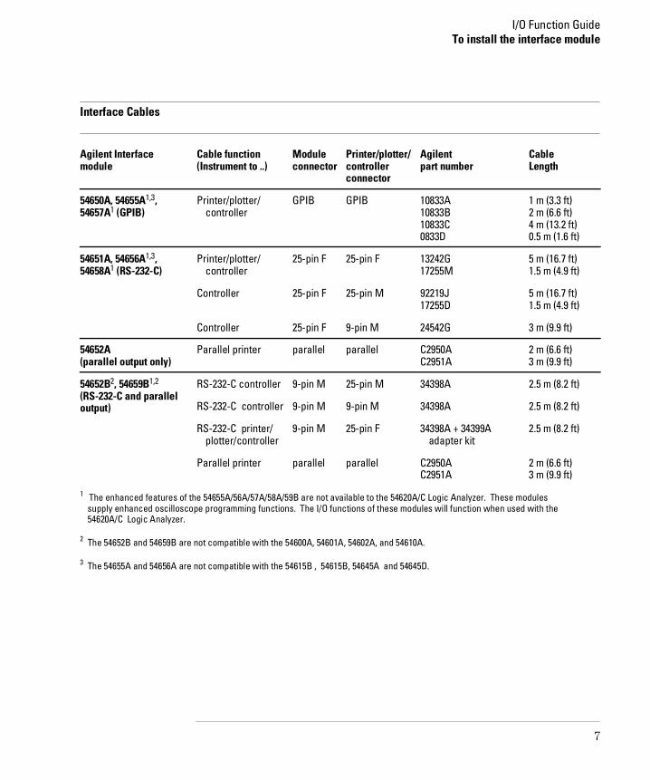
Interface Cables
Agilent Interfacemodule
Cable function(Instrument to ..)
Moduleconnector
Printer/plotter/controllerconnector
Agilent part number
CableLength
54650A, 54655A1,3,54657A1 (GPIB)
Printer/plotter/ controller
GPIB GPIB 10833A 10833B 10833C0833D
1 m (3.3 ft)2 m (6.6 ft)4 m (13.2 ft)0.5 m (1.6 ft)
54651A, 54656A1,3,54658A1 (RS-232-C)
Printer/plotter/ controller
25-pin F 25-pin F 13242G17255M
5 m (16.7 ft)1.5 m (4.9 ft)
Controller 25-pin F 25-pin M 92219J17255D
5 m (16.7 ft)1.5 m (4.9 ft)
Controller 25-pin F 9-pin M 24542G 3 m (9.9 ft)
54652A (parallel output only)
Parallel printer parallel parallel C2950AC2951A
2 m (6.6 ft)3 m (9.9 ft)
54652B2, 54659B1,2 (RS-232-C and paralleloutput)
RS-232-C controller 9-pin M 25-pin M 34398A 2.5 m (8.2 ft)
RS-232-C controller 9-pin M 9-pin M 34398A 2.5 m (8.2 ft)
RS-232-C printer/ plotter/controller
9-pin M 25-pin F 34398A + 34399A adapter kit
2.5 m (8.2 ft)
Parallel printer parallel parallel C2950AC2951A
2 m (6.6 ft)3 m (9.9 ft)
1 The enhanced features of the 54655A/56A/57A/58A/59B are not available to the 54620A/C Logic Analyzer. These modules supply enhanced oscilloscope programming functions. The I/O functions of these modules will function when used with the 54620A/C Logic Analyzer.
2 The 54652B and 54659B are not compatible with the 54600A, 54601A, 54602A, and 54610A.
3 The 54655A and 54656A are not compatible with the 54615B , 54615B, 54645A and 54645D.
I/O Function GuideTo install the interface module
7

Print/Utility Menu
The Print/Utility menu of your Agilent 54600-series instrument allowsyou to select I/O functions for the module you have connected to yourinstrument. The module can have an GPIB, RS-232-C, parallel, orcombination RS-232-C/parallel interface.
• To display this menu, press Print/Utility .
Print/Utility Menu
Print Screen pressing this softkey sends the screen image to your printer orplotter.
Interface setup
In many cases, the interface will need to be configured before attempting toprint. If you are setting up an GPIB module, refer to "To set GPIB addresses" onpage 17. If you are setting up an RS-232-C module, refer to "To set RS-232 baudrate and handshake" on page 18.
Hardcopy Menu this softkey allows you to select your printer or plotter typeand to set parameters for that printer or plotter.
I/O Menu this softkey allows you to set up parameters for your RS-232-C orGPIB interface for printer or controller operation.
Service Menu and System Config these softkeys control instrument andenhanced module functions such as service self-test, service self-calibrationand system configuration. Refer to your instrument User and Service Guide
or enhanced module User’s Guide for use of these softkeys.
Utility
8

To select your printer or plotter
• Press the Hardcopy Menu softkey to view printer/plotter options.Your module can be configured to print in several formats.
• To select the format of your printer/plotter, press the Format softkeyuntil the desired format is displayed.
Hardcopy Menu with RS-232-C or parallel module attached
Format Your module can be configured to print in the following formats:
LaserJet HP LaserJet format
DJ mono monochrome HP DeskJet format
DJ color color HP DeskJet format (color Agilent 54600-series instrumentsonly)
Epson Epson format
ThinkJet HP ThinkJet format (GPIB and RS-232-C modules only)
Plotter HP plotter (HP-GL) format. This format is available on GPIB andRS-232-C modules only and is not an option on color Agilent 54600instruments.
I/O Function GuideTo select your printer or plotter.
9

Destination If you have an RS-232-C/parallel dual interface module,press the Destination softkey to select the hardcopy output destination ofthe module to be RS-232 or Parallel.
Hardcopy Menu with RS-232-C/parallel dual interface module attached
Printer address If you have an GPIB interface module, press the PrintAddrsoftkey until the correct address is displayed. The address can also beincremented or decremented by turning the knob closest to the Cursors
key. The default printer/plotter address is 1.
Hardcopy Menu with GPIB module attached
I/O Function GuideTo select your printer or plotter.
10

To setup your printer or plotter
• From the Hardcopy Menu, press the Printer Setup softkey.
Selecting Printer Setup from the Hardcopy Menu
Printer/plotter options are displayed for formfeed, scale factors, and grayscale printing.
Printer setup options for Agilent LaserJet and Agilent DeskJet formats
I/O Function GuideTo setup your printer or plotter
11

To set formfeed
• To set formfeed, press the Hardcopy Menu softkey, then the Printer Setupsoftkey. Formfeed can be selected as On or Off The instrument will send a formfeed command after printing when Formfeedis set to On.
Formfeed is not an option when Format is set to Plotter.
I/O Function GuideTo set formfeed
12

To print or plot gray scale
Gray scale printing
• To print in gray scale, press the Hardcopy Menu softkey, then the PrinterSetup softkey. GrayScale can be selected as On or Off
Selecting GrayScale from the Printer Setup menu
When gray scale printing is selected, the full-bright and half-bright traces onthe instrument screen are printed on the hardcopy.
Gray scale printing requires an HP-PCL printer capable of at least 300 dpi(dots-per-inch), such as an HP LaserJet or HP DeskJet series printer. Grayscaleprinting is not available with ThinkJet and Epson formats. If you have a colorAgilent 54600-series instrument, DJ Color format will print in 2 different colors.
Gray scale print
I/O Function GuideTo print or plot gray scale
13

Gray scale plotting
1 Press the Hardcopy Menu softkey, then press the Format softkey untilPlotter is displayed.
Plotting GrayScale from the Plotter Setup menu
Gray scale plotting requires an HP-GL plotter capable of plotting with at least 2pens.
2 Press the Plotter Setup softkey, then press the Colors softkey until 2 isdisplayed.Gray scale plot uses two pens for the hardcopy. Half-bright traces are plottedwith plotter pen 1 and full-bright traces are plotted with plotter pen 2.
I/O Function GuideTo print or plot gray scale
14

To print or plot scale factors
Instrument scale factors may be turned on or off for hardcopy prints andplots. All factors are printed on the hardcopy when on is selected. Whenfactors is selected for a hardcopy plot, the plot is in portrait mode. Whenfactors is not selected for hardcopy plot, the plot is in landscape mode.
1 Press the Hardcopy Menu softkey, then press the Printer Setup softkey.2 Press the Factors softkey until On is displayed.
Print or Plot with Factors On (portrait mode)
I/O Function GuideTo print or plot scale factors
15

Plot with Factors Off (landscape mode)
I/O Function GuideTo print or plot scale factors
16

To set GPIB addresses
• To set addresses on GPIB modules, press Print/Utility , then pressthe I/O Menu softkey.
Setting GPIB addresses
This menu allows you to set the instrument and printer/plotter address.Each device on an GPIB bus must have a unique instrument adresss between0 and 30.
Instrument address
To set the instrument address, press the InstAddr softkey until the correctaddress is displayed. The address can also be incremented or decrementedby turning the knob closest to the Cursors key. The default instrumentaddress is 7.
Printer Address
To set the printer or plotter address on the GPIB bus, press the PrintAddrsoftkey until the correct address is displayed. The address can also beincremented or decremented by turning the knob closest to the Cursors key. The default printer/plotter address is 1.
See also For more information on GPIB parameters, refer to the Programmer’s Guidethat came with your Agilent 54600-Series instrument.
I/O Function GuideTo set GPIB addresses
17

To set RS-232 baud rate and handshake
• To set the baud rate and handshake parameters on a module with anRS-232 interface, press Print/Utility , then press the I/O Menusoftkey.
Setting RS-232-C baud rate and handshake
Baud rate
To set the RS-232 baud rate, press the Baud Rate softkey until the correctvalue is displayed. The baud rate can also be incremented or decrementedby turning the knob closest to the Cursors key. The baud rate can beselected as 1200, 2400, 9600, or 19200. The default baud rate is 9600.
Handshake
To set the RS-232 handshake protocol, press the Handshake softkey until thecorrect protocol is displayed.
Handshake can be set to DTR (data terminal ready) or XON (XON-transmit on/XOFF-transmit off.)
See also For more information on RS-232 parameters, refer to the Programmer’sGuide that came with your Agilent 54600-Series instrument.
I/O Function GuideTo set RS-232 baud rate and handshake
18

DECLARATION OF CONFORMITYaccording to ISO/IEC Guide 22 and EN 45014
Manufacturer’s Name: Agilent Technologies
Manufacturer’s Address: 1900 Garden of the Gods RoadColorado Springs , CO 80901 USA
Declares, That the product
Product Name: Digitizing Oscilloscope Module
Model Number(s): 54652B and 54659B
Product Options: All
Conforms to the following Product Specifications:
Safety: IEC 1010-1:1990 +A1 / EN 61010-1:1993UL 3111CSA-C22.2 No. 1010.1:1993
EMC: CISPR 11:1990 /EN 55011 (1991): Group 1 Class AIEC 555-2:1982 + A1:1985 / EN 60555-2:1987IEC 555-3:1982 + A1:1990 / EN 60555-3:1983 + A1:1991IEC 801-2:1991/EN 50082-1 (1992):4 kV CD, 8 kV ADIEC 801-3:1984/EN 50082-1 (1992):3 V/m, {1kHz 80% AM,27-1000MHz}IEC 801-4:1988/EN 50082-1 (1992): 0.5 kV Sig. Lines, 1kV Power Lines
Supplementary Information:The product herewith complies with the requirements of the Low VoltageDirective 73/23/EEC and the EMC Directive 89/336/EEC, and carries the CE-markingaccordingly.
This product was tested in a typical configuration with Agilent Technologies testsystems.
Colorado Springs, 1/12/95
European Contact: Your local Agilent Technologies Sales and Service Office or Agilent Technologies GmbH, Department ZQ /Standards Europe, Herrenberger Strasse 130, 71034 Böblingen Germany (FAX: +49-7031-143143)
John Strathman, Quality Manager

DECLARATION OF CONFORMITYaccording to ISO/IEC Guide 22 and EN 45014
Manufacturer’s Name: Agilent Technologies
Manufacturer’s Address: 1900 Garden of the Gods RoadColorado Springs , CO 80901 USA
Declares, That the product
Product Name: Digitizing Oscilloscope Module
Model Number(s): 54655A and 54656A
Product Options: All
Conforms to the following Product Specifications:
Safety: IEC 1010-1:1990 +A1 / EN 61010-1:1993UL 3111CSA-C22.2 No. 1010.1:1993
EMC: CISPR 11:1990 /EN 55011 (1991): Group 1 Class AIEC 555-2:1982 + A1:1985 / EN 60555-2:1987IEC 555-3:1982 + A1:1990 / EN 60555-3:1983 + A1:1991IEC 801-2:1991/EN 50082-1 (1992):4 kV CD, 8 kV ADIEC 801-3:1984/EN 50082-1 (1992):3 V/m, {1kHz 80% AM,27-1000MHz}IEC 801-4:1988/EN 50082-1 (1992): 0.5 kV Sig. Lines, 1kV Power Lines
Supplementary Information:The product herewith complies with the requirements of the Low VoltageDirective 73/23/EEC and the EMC Directive 89/336/EEC, and carries the CE-markingaccordingly.
This product was tested in a typical configuration with Agilent Technologies testsystems.
Colorado Springs, 1/14/97
European Contact: Your local Agilent Technologies Sales and Service Office or Agilent Technologies GmbH, Department ZQ /Standards Europe, Herrenberger Strasse 130, 71034 Böblingen Germany (FAX: +49-7031-143143)
John Strathman, Quality Manager

DECLARATION OF CONFORMITYaccording to ISO/IEC Guide 22 and EN 45014
Manufacturer’s Name: Agilent Technologies
Manufacturer’s Address: 1900 Garden of the Gods RoadColorado Springs , CO 80901 USA
Declares, That the product
Product Name: Digitizing Oscilloscope Module
Model Number(s): 54657A and 54658A
Product Options: All
Conforms to the following Product Specifications:
Safety: IEC 1010-1:1990 +A1 / EN 61010-1:1993UL 3111CSA-C22.2 No. 1010.1:1993
EMC: CISPR 11:1990 /EN 55011 (1991): Group 1 Class AIEC 555-2:1982 + A1:1985 / EN 60555-2:1987IEC 555-3:1982 + A1:1990 / EN 60555-3:1983 + A1:1991IEC 801-2:1991/EN 50082-1 (1992):4 kV CD, 8 kV ADIEC 801-3:1984/EN 50082-1 (1992):3 V/m, {1kHz 80% AM,27-1000MHz}IEC 801-4:1988/EN 50082-1 (1992): 0.5 kV Sig. Lines, 1kV Power Lines
Supplementary Information:The product herewith complies with the requirements of the Low VoltageDirective 73/23/EEC and the EMC Directive 89/336/EEC, and carries the CE-markingaccordingly.
This product was tested in a typical configuration with Agilent Technologies testsystems.
Colorado Springs, 4/24/97
European Contact: Your local Agilent Technologies Sales and Service Office or Agilent Technologies GmbH, Department ZQ /Standards Europe, Herrenberger Strasse 130, 71034 Böblingen Germany (FAX: +49-7031-143143)
John Strathman, Quality Manager


Copyright AgilentTechnologies 1991-1996, 2000All Rights Reserved.
Reproduction, adaptation, ortranslation without priorwritten permission isprohibited, except as allowedunder the copyright laws.
Document Warranty
The information contained inthis document is subject tochange without notice.Agilent Technologies
makes no warranty of any
kind with regard to this
material, including, but
not limited to, the implied
warranties or
merchantability and
fitness for a particular
purpose.
Agilent Technologies shallnot be liable for errorscontained herein or forincidental or consequentialdamages in connection withthe furnishing, performance,or use of this material.Complete product warrantyinformation is given at theend of this manual.
Safety
This apparatus has beendesigned and tested inaccordance with IECPublication 348, SafetyRequirements for MeasuringApparatus, and has beensupplied in a safe condition.This is a Safety Class Iinstrument (provided withterminal for protectiveearthing). Before applyingpower, verify that the correctsafety precautions are taken(see the following warnings).In addition, note the externalmarkings on the instrumentthat are described under"Safety Symbols."
Warning
• Before turning on theinstrument, you must connectthe protective earth terminalof the instrument to theprotective conductor of the(mains) power cord. Themains plug shall only beinserted in a socket outletprovided with a protectiveearth contact. You must notnegate the protective actionby using an extension cord(power cable) without aprotective conductor(grounding). Grounding oneconductor of a two-conductoroutlet is not sufficientprotection.
• Only fuses with therequired rated current,voltage, and specified type(normal blow, time delay,etc.) should be used. Do notuse repaired fuses orshort-circuited fuseholders.To do so could cause a shockof fire hazard.
• Service instructions are fortrained service personnel. Toavoid dangerous electricshock, do not perform anyservice unless qualified to doso. Do not attempt internalservice or adjustment unlessanother person, capable ofrendering first aid andresuscitation, is present.
• If you energize thisinstrument by an autotransformer (for voltagereduction), make sure thecommon terminal isconnected to the earthterminal of the power source.
• Whenever it is likely thatthe ground protection isimpaired, you must make theinstrument inoperative andsecure it against anyunintended operation.
• Do not operate theinstrument in the presence offlammable gasses or fumes.Operation of any electricalinstrument in such anenvironment constitutes adefinite safety hazard.
• Do not install substituteparts or perform anyunauthorized modification tothe instrument.
• Capacitors inside theinstrument may retain acharge even if the instrumentis disconnected from itssource of supply.
• Use caution when exposingor handling the CRT.Handling or replacing theCRT shall be done only byqualified maintenancepersonnel.
Safety Symbols
Instruction manual symbol:the product is marked withthis symbol when it isnecessary for you to refer tothe instruction manual inorder to protect againstdamage to the product.
Hazardous voltage symbol.
Earth terminal symbol: Usedto indicate a circuit commonconnected to groundedchassis.
W A R N I N G
The Warning sign denotes ahazard. It calls attention to aprocedure, practice, or thelike, which, if not correctlyperformed or adhered to,could result in personalinjury. Do not proceedbeyond a Warning sign untilthe indicated conditions arefully understood and met.
C A U T I O N
The Caution sign denotes ahazard. It calls attention toan operating procedure,practice, or the like, which, ifnot correctly performed oradhered to, could result indamage to or destruction ofpart or all of the product. Donot proceed beyond aCaution symbol until theindicated conditions are fullyunderstood or met.
Agilent TechnologiesP.O. Box 21971900 Garden of the Gods RoadColorado Springs, CO 80901
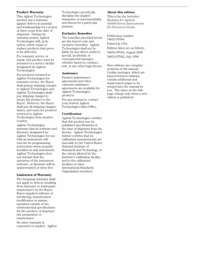
Product Warranty
This Agilent Technologiesproduct has a warrantyagainst defects in materialand workmanship for a periodof three years from date ofshipment. During thewarranty period, AgilentTechnologies will, at itsoption, either repair orreplace products that proveto be defective.For warranty service orrepair, this product must bereturned to a service facilitydesignated by AgilentTechnologies.For products returned toAgilent Technologies forwarranty service, the Buyershall prepay shipping chargesto Agilent Technologies andAgilent Technologies shallpay shipping charges toreturn the product to theBuyer. However, the Buyershall pay all shipping charges,duties, and taxes for productsreturned to AgilentTechnologies from anothercountry.Agilent Technologieswarrants that its software andfirmware designated byAgilent Technologies for usewith an instrument willexecute its programminginstructions when properlyinstalled on that instrument.Agilent Technologies doesnot warrant that theoperation of the instrumentsoftware, or firmware will beuninterrupted or error free.
Limitation of Warranty
The foregoing warranty shallnot apply to defects resultingfrom improper or inadequatemaintenance by the Buyer,Buyer-supplied software orinterfacing, unauthorizedmodification or misuse,operation outside of theenvironmental specificationsfor the product, or impropersite preparation ormaintenance.No other warranty isexpressed or implied. Agilent
Technologies specificallydisclaims the impliedwarranties or merchantabilityand fitness for a particularpurpose.
Exclusive Remedies
The remedies provided hereinare the buyer’s sole andexclusive remedies. AgilentTechnologies shall not beliable for any direct, indirect,special, incidental, orconsequential damages,whether based on contract,tort, or any other legal theory.
Assistance
Product maintenanceagreements and othercustomer assistanceagreements are available forAgilent Technologiesproducts.For any assistance, contactyour nearest AgilentTechnologies Sales Office.
Certification
Agilent Technologies certifiesthat this product met itspublished specifications atthe time of shipment from thefactory. Agilent Technologiesfurther certifies that itscalibration measurements aretraceable to the United StatesNational Institute ofStandards and Technology, tothe extent allowed by theInstitute’s calibration facility,and to the calibrationfacilities of otherInternational StandardsOrganization members.
About this edition
This is the the Interface
Modules for Agilent
54600-Series Instruments
I/O Function Guide.
Publication number54652-97004Printed in USA.Edition dates are as follows:54652-97004, August 200054652-97002, July 1996
New editions are completerevisions of the manual.Update packages, which areissued between editions,contain additional andreplacement pages to bemerged into the manual byyou. The dates on the titlepage change only when a newedition is published.