Embed Size (px)
Citation preview

Intention-Based Walking Support for Paraplegia Patients with Robot Suit HAL 383
Intention-Based Walking Support for Paraplegia Patients with Robot Suit HAL
Kenta Suzuki, Gouji Mito, Hiroaki Kawamoto, Yasuhisa Hasegawa and Yoshiyuki Sankai
0
Intention-Based Walking Support for
Paraplegia Patients with Robot Suit HAL
Kenta Suzuki1, Gouji Mito1, Hiroaki Kawamoto2,Yasuhisa Hasegawa1 and Yoshiyuki Sankai1
1Graduate School of Systems and Information Engineering, University of Tsukuba2Japan Association for the Advancement of Medical Equipment
Tennodai 1-1-1, Tsukuba, 305-8573, JapanEmail: [email protected]
Abstract
This paper proposes an algorithm to estimate human intentions related with walking in or-der to comfortably and safely support a paraplegia patient’s walk. A robot suit “HAL” hasbeen developed for an enhancement of healthy person’s activities and for support of physi-cally challenged person’s daily life. Assisting method based on bioelectrical signals such asmyoelectricity successfully supports healthy person’s walking. These bioelectrical signals,however, cannot be measured properly from a paraplegia patient. Therefore another inter-face that can estimate patients’ intentions without any manual controller are desired for robotcontrol since a manual controller deprives a patient of his/her hands’ freedom. Estimationof patients’ intentions contributes to support not only comfortably but also safely, because aninconformity between the robot suit motion and the patient motion results in his/her stum-bling or falling. The proposed algorithm, therefore, estimates patient’s intentions from a floorreaction force reflecting patient’s weight shift during walking and standing. The effectivenessof this algorithm is investigated through experiments on a paraplegia patient who has a sen-sory paralysis on both legs, especially his left leg. We show that HAL supports patient’s walkproperly, estimating his intentions based on floor reaction force.Keywords: robot suit, paraplegia, walking support, intention estimation, floor reaction force
1. INTRODUCTION
People may have muscle rigidity, relaxation, involuntary contraction of muscle, and sensoryparalysis due to cerebral paralysis, stroke, spinal cord injury, muscular dystrophy and post-polio syndrome. Even if people do not suffer from these physical problems, aging bringsvarious troubles on his/her motility. Most people who have problems on the lower limbsdue to these symptoms or aging are unable to walk and are bedridden all day long at worst.Moreover, this situation depresses the patients’ feelings, for instance bedridden patients losehis/her life worth living. Caregivers including the patient’s family also receive hard works tolook after him/her, once a person has a trouble in the motility. To relieve these problems andto support the patient’s independent life, it is quite important to provide a safe and convenienttransportation device. A wheelchair is now used in most cases as a transportation device for
23
www.intechopen.com
Climbing and Walking Robots384
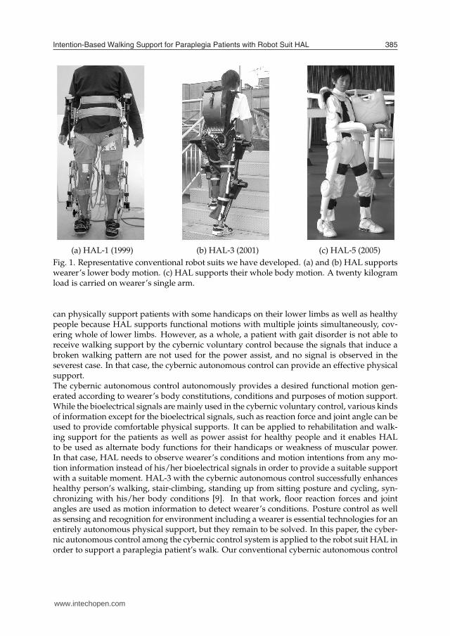
patients with gait disorder. It is convenient for the patients because they can move easily aslong as an enough muscular power is left in their upper body. Even if a patient has weaknessof the arms, a motorized wheelchair could be used. However, wheelchairs have some prob-lems in its using environment and the user’s posture. Especially, wheelchair users are apt tokeep sitting posture for a long time and have less opportunities to exercise their own lowerbodies. That may cause a decrease in not only muscular power of lower body with paralysisbut also residual physical functions. This problem could be solved if a patient with paraplegiacould walk on his/her legs as a healthy person does. Therefore, a device which helps a patientwalk in his/her standing posture would be one of the solutions since he/she can locomotewith his/her leg receiving a physical support. Several devices for walking support have beendeveloped. In our study, a wearable type robot “Robot suit HAL (Hybrid Assistive Limb)”has been developed in order to physically support wearer’s daily activities and heavy works.HAL-1 utilizing DC motors and ball screws shown in Fig. 1(a) was developed as the firstprototype of HAL [1], and it enhanced wearer’s walking by amplifying wearer’s own jointtorque. After developing some prototypes, HAL-3 shown in Fig. 1(b) was developed towarda more suitable system to be used in actual daily life [2, 3]. These robot suits have a powerunit on each hip and knee joint, and they support functional motions of lower limbs withmultiple joints simultaneously. After that, HAL-5 (see Fig. 1(c)), that is demonstrated at the2005 World Exposition in Aichi, has been developed for whole body support. It assists humanmotions involving wearer’s upper-body activities such as carrying heavy loads. Meanwhile,“RoboKnee” [4] and “Wearable Walking Helper” [5] have been developed to support the kneemotion by using linear actuators. However, it is difficult for these two devices to support apatient with paraplegia since these devices cannot support their multiple joints in lower limbssimultaneously. As an exoskeleton to assist soldiers, disaster relief workers and other emer-gency personnel who needs to move long distance on foot on their fields, Kazerooni et al.,[6, 7] has developed “BLEEX” that supports human’s walking while carrying heavy loads onhis/her back. This exoskeleton is not designed for welfare purposes, and it is too large andheavy (75 kg including exoskeleton weight and maximum payload) for patients to handle astheir own supporting devices in actual daily life. To provide effective physical support accord-ing to each wearer’s condition, it is necessary to strongly focus on control algorithm as wellas mechanism of supporting devices. The robot suit HAL has a cybernic control system thatis a hybrid control algorithm consisted of “Cybernic voluntary control (Bio-cybernic control)”and “Cybernic autonomous control (Cybernic robot control)”. The cybernic control systemcan provide suitable physical support to wearers in various conditions such as a healthy per-son, a physically challenged person and so on by using two algorithms as complementarycontrols.The features of each control algorithm are described below. The cybernic voluntary controlprovides physical support according to his/her voluntary muscle activity. Power units ofHAL generate power assist torque by amplifying wearer’s own joint torque estimated fromhis/her bioelectrical signals, and the support motions are consequently controlled by wear’ssignal adjustment. This control was used for power assist of healthy person’s activities [8], forexample walking and standing up from sitting posture, and we confirmed the cybernic vol-untary control successfully supported a wearer’s motion. The bioelectrical signals includingmyoelectricity are useful and reliable information to estimate human’s motion intentions be-cause the signals are measured just before corresponding muscle activities. Thus, the wearersreceive the physical support directly by unconscious interface using the bioelectrical signals,which realize much more easily operation than manual controllers such as a joystick. HAL
www.intechopen.com
Intention-Based Walking Support for Paraplegia Patients with Robot Suit HAL 385
(a) HAL-1 (1999) (b) HAL-3 (2001) (c) HAL-5 (2005)
Fig. 1. Representative conventional robot suits we have developed. (a) and (b) HAL supportswearer’s lower body motion. (c) HAL supports their whole body motion. A twenty kilogramload is carried on wearer’s single arm.
can physically support patients with some handicaps on their lower limbs as well as healthypeople because HAL supports functional motions with multiple joints simultaneously, cov-ering whole of lower limbs. However, as a whole, a patient with gait disorder is not able toreceive walking support by the cybernic voluntary control because the signals that induce abroken walking pattern are not used for the power assist, and no signal is observed in theseverest case. In that case, the cybernic autonomous control can provide an effective physicalsupport.The cybernic autonomous control autonomously provides a desired functional motion gen-erated according to wearer’s body constitutions, conditions and purposes of motion support.While the bioelectrical signals are mainly used in the cybernic voluntary control, various kindsof information except for the bioelectrical signals, such as reaction force and joint angle can beused to provide comfortable physical supports. It can be applied to rehabilitation and walk-ing support for the patients as well as power assist for healthy people and it enables HALto be used as alternate body functions for their handicaps or weakness of muscular power.In that case, HAL needs to observe wearer’s conditions and motion intentions from any mo-tion information instead of his/her bioelectrical signals in order to provide a suitable supportwith a suitable moment. HAL-3 with the cybernic autonomous control successfully enhanceshealthy person’s walking, stair-climbing, standing up from sitting posture and cycling, syn-chronizing with his/her body conditions [9]. In that work, floor reaction forces and jointangles are used as motion information to detect wearer’s conditions. Posture control as wellas sensing and recognition for environment including a wearer is essential technologies for anentirely autonomous physical support, but they remain to be solved. In this paper, the cyber-nic autonomous control among the cybernic control system is applied to the robot suit HAL inorder to support a paraplegia patient’s walk. Our conventional cybernic autonomous control
www.intechopen.com

Climbing and Walking Robots386
algorithm [9] cannot be applied to them directly due to variety of patients’ body constitutionsand handicaps. Generally, the human intentions in his/her mind are essentially independentfrom the physical interactions between a body and an environment. As far as we know, nocurrent technologies can directly measure and extract the human intentions. However, wecan sometimes guess the human intentions in his/her mind from his/her appearances or mo-tions. Besides, we can estimate his/her corresponding intentions if we observe a motion oran appearance that is closely connected with his/her intentions. According to conventionalworks on human transient walking [10, 11], a COG shift to one leg is prior motion to a walk.That motion is an indispensable to swing a leg and can be observed earlier than a bioelectri-cal signal such as myoelectricity, because it is observed before a human starts swinging a leg,while a bioelectrical signal is observed when corresponding muscles start contracting. TheCOG shift can be used for an early and smart trigger to start walking supports, because theshift is involved into preliminary motions for a walk and human does not have to operate anymanual switch to start the walking supports. On the other hand, gait stopping is similar to thetime-reverse motion of the gait initiation, and the COG stops at around the center of both sup-porting legs. Therefore this paper proposes an intention estimator that can estimate his/herwalking intentions from the COG shift that is closely connected with his/her intention. Wedefine that intention-based support (including the walking support) is to provide a physicalsupport for the next wearer’s desired motion that can be predicted based on the current stateor motion induced by his/her intention. In a case of walking, a human shifts the COG to asupporting leg side before he/she starts swinging a leg. If the robot suit HAL can sense theCOG shift induced by his/her intention, it can predict his/her walking start and then startwalking support. Our project aims to realize the comfortable walking supports for paraplegiapatients that reflect the patients’ intentions on the start and stop of walking, cycle and strideof walking motion, walking direction and so on. We call the walking support conforming tothese various intentions of walking “Intention-based walking support”. It is hoped that theintention-based walking support improves the usability, safety and reliability of the robot suitHAL. As the first step, this paper focuses on three kinds of intentions: start and stop of walk-ing and the beginning to swing a leg, and proposes a control algorithm that uses patient’sresidual physical functions effectively. We need to observe not only the COG shift in a lateralplane but also the forward COG shift and bending of the upper body in order to distinguishthe gait initiation from other similar motions such as just stepping or changing a supportingleg for a leg relaxation. However, the robot suit HAL can understand his/her intention if weinstruct the wearer to shift the COG to either of his/her legs in order to receive the physicalsupport for swinging a leg. Therefore, floor reaction force can be one of reliable informationthat reflects his/her intentions without any manual interfaces if a patient can control his/herweight balance in lateral plane by holding a walking frame with own hands. The purposeof this study is that HAL helps a patient with paraplegia walk in a standing posture. Basedon our conventional works, two additional functions should be developed for this purpose.First, HAL should generate a suitable bipedal walk according to patient’s body constitutions.Reference trajectories for each joint support should be designed in another way because thebioelectrical signals are not observed from a patient with paraplegia. The reference motionsconsist of swinging wearer’s leg, supporting his/her weight and shifting his/her weight fromone leg to the other. Second, HAL should provide walking support according to patient’sintentions that are estimated from wearer’s COG shift. To achieve two functions mentionedabove, this paper takes the following approaches. They are:
www.intechopen.com

Intention-Based Walking Support for Paraplegia Patients with Robot Suit HAL 387
1. To achieve the bipedal locomotion partially based on walking patterns of a healthy per-son,
2. To estimate wearer’s intentions from his/her COG shift that is observed by the floorreaction force and
3. To synchronize support motions with estimated wearer’s intentions: the walk start, stopand the beginning to swing a leg.
The following section explains assumptions and approach of this study. Section 3 introducesthe robot suit “HAL-5 Type-C” used in this experiment. Section 4 describes the proposedalgorithm for walking support and intention estimation. Section 5 shows experimental resultsand verifies the performance of the proposed algorithm in HAL-5 Type-C. Finally, section 6 isthe conclusion.
2. ASSUMPTIONS AND APPROACH
In this paper, a proposed algorithm is applied to the walking support for a paraplegia pa-tient called “subject A” in this paper. He has sensory paralysis on both legs, especially left legbecause of spinal cord injury by traffic accident. He can keep standing posture and slowlywalk by himself with two canes. In this case, we cannot measure proper bioelectrical sig-nals to estimate his intention during walking because of disorder of neural transmission. We,therefore, use floor reaction force instead of the bioelectrical signals in this experiment. Floorreaction force (FRF) reflects his weight shift during walking and standing. It should be notedthat he can control his balance holding a walking frame and that our algorithm can estimatehis intentions from his FRF. That is our algorithm synchronizes the physical support with hisintentions through his controlled weight balance by using not any manual controllers suchas a joystick but FRF during walking and standing. The reference patterns to the patient areextracted from healthy person’s walk. The healthy person’s walking motion could be suitableto the patient if he/she has the same body constitution as the healthy person. The extractedwalking motion, however, should be adjusted according to the patient’s body constitutionand handicap conditions, for example a walking cycle and amplitude of each joint trajectoryin swinging a leg.
3. ROBOT SUIT HAL
In the experiment, the robot suit HAL-5 clinical type (HAL-5 Type-C) which is made for thesubject A is used. Figure 2 shows the overview of HAL-5 Type-C and Fig. 3 is its systemconfigurations. As in the case of the conventional type of HAL (HAL-3), HAL-5 Type-C con-sists of power units, exoskeletal frames, sensors and a controller. Power units are attached oneach hip and knee joints and actuate each joint by their torques. On ankle joints, springs areattached so that wearer’s ankle joints could come back to a normal angle even if any externalforces do not affect the joints. The spring action contributes to avoiding collisions between atoe of a swing leg and a floor. The exoskeletal frames are fixed to wearer’s legs with moldedplastic bands, and transmit torques of the power units to his/her legs. There are angularsensors and FRF sensors to measure motion information of HAL-5 Type-C and a wearer forwearer’s intention estimation. Potentiometers as angular sensors are attached to the each jointto measure the joint angles. FRF sensors utilizing the semiconductor-type pressure sensor areimplemented in shoes. Figure 4 shows the appearance of the shoes of HAL-5 Type-C withbuilt-in FRF sensors. The weight of a wearer including HAL-5 Type-C is transferred onto the
www.intechopen.com

Climbing and Walking Robots388
sensor unit and measured by the pressure sensors. These sensors can also measure the distri-bution of load between a toe part and a heel part during walking and standing because twosensors are built in the front and rear of the shoe sole inside. In addition, a computer and bat-teries are attached on a wearer’s waist, and motor drivers and other electrical circuits for thesignal processing are allocated on each power unit. Compared with the robot suit HAL-3 (seeFig. 1(b)), HAL-5 Type-C is improved for patients’ daily use since there is no large backpackon his/her back and a width of the power units in the back view becomes thin enough to passthrough narrow spaces as shown in Fig. 2. Figure 5 shows angles and rotation directions ofeach joint described in this paper.
4. CONTROLLER DESIGN
In this section, we explain a controller for walking support system. Walking motion in thiswork shall be consist of three functions including swinging a leg, landing and supporting abody as shown in Fig. 6. In this paper, we call each span of three functions “swing phase”,“landing phase” and “support phase”. In the swing phase, the patterns extracted from healthyperson’s walk are applied as the reference patterns of the proportional and derivative (PD)control for the corresponding joints of a wearer. The reference patterns are used for the cor-responding leg’s control synchronizing with wearer’s intention estimated by our proposedalgorithm. In the landing phase, we realize the leg function for a foot landing by not trackingreference patterns but applying constant-value control. Based on our conventional work [12],we found that the knee joint of a wearer at landing instance is apt to be flexed by his/herown weight and much torque beyond the torque tolerance is needed to compensate for theknee bend. Therefore the knee joint has to be extended earlier than the reference pattern byconstant-value control. In the support phase as well as the landing phase, the leg is sup-ported by constant-value control in order to support his weight by one leg. The followingsub-sections explain the details of the controller algorithm.
(a) Back view. (b) Side view.
Fig. 2. HAL-5 Type-C developed for walking support of a paraplegia patient. Total weight is15 kg.
www.intechopen.com

Intention-Based Walking Support for Paraplegia Patients with Robot Suit HAL 389
Fig. 3. System configurations of HAL-5 Type-C.
Fig. 4. Built-in floor reaction force sensors.
Fig. 5. Rotation directions of each joint.
www.intechopen.com

Climbing and Walking Robots390
Fig. 6. Three functions in walking motion.
4.1 Reference pattern generation
As mentioned above, a swing leg in the swing phase is supported by applying reference walk-ing patterns measured in healthy person’s walk. The reference patterns are generated in thefollowing process.
1. To measure angle data of hip and knee joints in healthy person’s walk.
2. To divide a sequence of the measured walk pattern into patterns of each step and thenaverage the walk patterns.
3. To divide the averaged pattern into three phases and extract a pattern in the swingphase.
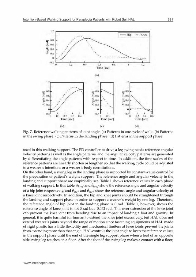
At first, we measure a healthy person’s walk to acquire the angle data of hip and knee jointsduring walk. In this experiment, we measure a normal walk of a man in his twenties, whohas the similar body constitutions including height, weight and length of legs to the subjectA. Second, a sequence of the measured walk pattern is divided into patterns in each step andthen they are averaged. At this stage, we should pay attention that habits of walking andasymmetry between right and left leg step are not reflected in the extracted patterns strongly.Figure 7(a) shows walking patterns in one step averaged in this experiment.Finally, the averaged walking patterns are divided into patterns in the swing, landing andsupport phase. The swing phase is between a moment when a foot leaves a floor and a mo-ment when a thigh is full flexed. The landing phase continues until a moment when a footof the swing leg contacts a ground, and the support phase continues until a moment whenone step finishes. The walking patterns extracted from a healthy person’s walk are shown inFig. 7(b), (c) and (d). Namely, Fig. 7(b) shows the reference angle patterns in the swing phase
www.intechopen.com
Intention-Based Walking Support for Paraplegia Patients with Robot Suit HAL 391
Fig. 7. Reference walking patterns of joint angle. (a) Patterns in one cycle of walk. (b) Patternsin the swing phase. (c) Patterns in the landing phase. (d) Patterns in the support phase.
used in this walking support. The PD controller to drive a leg swing needs reference angularvelocity patterns as well as the angle patterns, and the angular velocity patterns are generatedby differentiating the angle patterns with respect to time. In addition, the time scales of thereference patterns are linearly shorten or lengthen so that the walking cycle could be adjustedto a wearer’s intentions or a wearer’s body constitutions.On the other hand, a swing leg in the landing phase is supported by constant-value control forthe preparation of patient’s weight support. The reference angle and angular velocity in thelanding and support phase are empirically set. Table 1 shows reference values in each phaseof walking support. In this table, θhre f and θ̇hre f show the reference angle and angular velocity
of a hip joint respectively, and θkre f and θ̇kre f show the reference angle and angular velocity ofa knee joint respectively. In addition, the hip and knee joints should be straightened throughthe landing and support phase in order to support a wearer’s weight by one leg. Therefore,the reference angle of hip joint in the landing phase is 0 rad. Table 1, however, shows thereference angle of knee joint is not 0 rad but -0.052 rad. This over extension of the knee jointcan prevent the knee joint from bending due to an impact of landing a foot and gravity. Ingeneral, it is quite harmful for human to extend the knee joint excessively, but HAL does notextend wearer’s joints beyond the range of motion since fastening equipments of HAL madeof rigid plastic has a little flexibility and mechanical limiters at knee joints prevent the jointsfrom extending more than that angle. HAL controls the joint angle to keep the reference valuesin the support phase until the end of the single leg support phase when a foot of an oppositeside swing leg touches on a floor. After the foot of the swing leg makes a contact with a floor,
www.intechopen.com

Climbing and Walking Robots392
Swing phase Landing phase Support phase
θhre f [rad] Fig. 7(b) 0.0 0.0 (-0.7)
θ̇hre f [rad/sec] Time derivative of Fig. 7(b) 0.0 0.0
θkre f [rad] Fig. 7(b) -0.052 -0.052
θ̇kre f [rad/sec] Time derivative of Fig. 7(b) 0.0 0.0
Table 1. Reference values in one cycle of walking support.
the reference hip joint angle of the supporting leg switches from 0.0 rad to -0.7 rad shownin parentheses of Table 1. This hip extension contributes to the smooth weight shift from acurrent supporting leg to a following one. Reference angular velocity of both joints in thelanding and support phase consistently maintains 0.0 rad/sec through one cycle of walkingsupport.
4.2 Intention estimator
Estimation of patients’ intentions contributes to support not only comfortably but also safely,because an inconformity between the robot suit motion and the patient motion results in hisstumbling or falling. Instead of the bioelectrical signals used for the control of the conven-tional HAL, the floor reaction force is used for an intention estimation of the subject A whocan control his weight balance using two canes with his hands. The floor reaction force re-flects the position of center of gravity (COG) and COG could be the reliable information forthe intention estimation. For example, a leg could leave a floor and work as a swing leg safelyif it does not support his/her weight. A support system “HAL” estimates which leg supportsa wearer’s weight, when a wearer begins to swing a right or left leg and when he/she wantsto stop walking. At first, for example, a right leg is considered to be a support leg when a footcontact condition:
frh > αrh or (1)
frt > αrt (2)
is satisfied, where frh and frt are FRF of a right foot heel side and toe side, respectively. Inaddition, αrh and αrt are thresholds to detect a landing of a right foot. In general, the condition(1) is applied in advance of (2) since a healthy person puts a heel of a swing leg on a floor inadvance of a toe. Patients with paralysis on legs such as the subject A, however, have a footweighed down and may put a toe of a swing leg on a floor in advance of a heel. The condition(2) is effective in detecting the landing in cases of paraplegia patients. On the other hand, aleft leg is considered to be a support leg when a foot contact condition:
flh > αlh or (3)
flt > αlt (4)
is satisfied, where flh and flt are FRF of a left foot heel side and toe side, respectively. Inaddition, αlh and αlt are thresholds to detect a landing of a left foot.Second, for example, HAL estimates the intention that a wearer wants to swing a right legwhen swing start conditions:
frh < βrh and (5)
www.intechopen.com

Intention-Based Walking Support for Paraplegia Patients with Robot Suit HAL 393
frt < βrt (6)
are satisfied, where βrh and βrt are thresholds to detect a moment when each part of a rightfoot leaves a floor. On the other hand, HAL estimates the intention that a wearer wants toswing a left leg when swing start conditions:
flh < βlh and (7)
flt < βlt (8)
are satisfied, where βlh and βlt are thresholds to detect a moment when each part of a left footleaves a floor. In this study, the following two constraint conditions are added to the aboveconditions for more stable estimation of wearer’s intentions.
1. Do not start to swing a leg unless a foot of the opposite side leg is on a floor.
2. Do not swing the same leg sequentially.
HAL estimates the intention that a wearer wants to stop in his/her tracks if it pasts a certaintime before the swing start conditions (5) and (6), or (7) and (8) are satisfied. In the walkingsupport, HAL stops the sequential walking supports and helps a wearer come back to thestanding posture when a condition:
tcur − tr > Twait or (9)
tcur − tl > Twait (10)
is satisfied, where tcur, tr and tl are the current time and the time when the last right or left foottouches on a floor. In addition, Twait is a temporal threshold to switch the walking supportto the standing posture support. In this moment, the reference angles of all joints are almostzero, therefore a backward leg is replaced around a forward leg if a load on the backward legbecomes almost zero by his/her weight shift. We set Twait = 5.0 sec in this experiment.
4.3 Control Architecture
Bipedal locomotion using patient’s legs is achieved by the tracking control and by phase syn-chronization of motion support with patient’s intention. This control consists of the PD controlusing reference walking patterns based on healthy person’s walk as shown in Fig. 7(a) in theswing phase and the constant-value control in the landing and support phase. Figure 8 showsa block diagram for this tracking control and phase synchronization. The human intentionestimator (HIE) located in the upper-left part in the figure has the FRF as inputs for the es-timation algorithms described in the section 4.2. Three blocks under the HIE are a library ofthe reference patterns in the swing phase and the reference values in the landing and supportphase. The HIE allocates these references to two legs during walking. There are six ordinaryPD control blocks on the right side of the HIE and the library. The upper three blocks arecontrollers for the right leg and the lower ones are for the left leg. The command voltages τr
and τl to the power units on both legs are calculated by:
τr = Kr(Crθre f − θr) + K̂r(Crθ̇re f − θ̇r) and (11)
www.intechopen.com

Climbing and Walking Robots394
τl = Kl(Clθre f − θl) + K̂l(Cl θ̇re f − θ̇l), (12)
where θr and θl are the actual wearer’s leg joint angles, θ̇r and θ̇l are angular velocities andsubscripts r and l mean right and left, respectively. In addition, θre f and θ̇re f are the referencejoint angles and the reference angular velocities, respectively. These variables including τr andτl have two elements that correspond to two joints: hip and knee joint. τr, τl ,θr,θl , θ̇r, θ̇l ,θre f
and θ̇re f are given as follows:
τr =
[
τrh
τrk
]
, τl =
[
τlh
τlk
]
, (13)
θr =
[
θrh
θrk
]
, θl =
[
θlh
θlk
]
, θ̇r =
[
θ̇rh
θ̇rk
]
, θ̇l =
[
θ̇lh
θ̇lk
]
, (14)
θre f =
[
θhre f
θkre f
]
, θ̇re f =
[
θ̇hre f
θ̇kre f
]
, (15)
where subscripts rh, rk, lh and lk mean right hip joint, right knee joint, left hip joint and leftknee joint, respectively. On the other hand, Kr and Kl are feedback gains of the joint angleerrors, and K̂r and K̂l are feedback gains of the joint angular velocity errors. The differentfeedback gains are used in the swing, landing or support phase independently by adoptingthis control architecture. In addition, Cr and Cl are gains to the reference joint angles andangular velocities. These gains can adjust a joint flexion and a stride length in a wearer’ssupported walk. In this experiment, we set Cl larger than Cr in order to avoid collisions of aleft leg which has a more severe paralysis with a floor in the swing phase. Kr,Kl , K̂r, K̂l ,Cr
and Cl are diagonal matrixes which are given as follows:
Kr =
[
krh 00 krk
]
, Kl =
[
klh 00 klk
]
, K̂r =
[
k̂rh 0
0 k̂rk
]
, K̂l =
[
k̂lh 0
0 k̂lk
]
,
(16)
Cr =
[
crh 00 crk
]
, Cl =
[
clh 00 clk
]
. (17)
Moreover, the PD gains of swing leg control krh, klh, k̂rh, k̂lh, krk, klk, k̂rk and k̂lk were deter-mined based on frequency responses and step responses of hip and knee joints. The concreteprocedure is described in Appendix A.The control flow for the walking support is as follows. At first, HAL supports a wearer’sstanding posture. Once the conditions shown in the equations (5) and (6) are satisfied, HALstarts the PD control for the swing phase in a right leg and for the support phase in a left leg.On the other hand, HAL starts the PD control for the swing phase in a left leg and the supportphase in a right leg once the conditions shown in the equations (7) and (8) are satisfied. ThePD control for a swing leg continues until HAL finishes the reference swing patterns. Afterthat, HAL runs the constant-value control for the landing phase until the condition shownin the equation (1) or (2) is satisfied in a case of a right leg and until the condition shown inthe equation (3) or (4) is satisfied in a case of a left leg. The other leg continues the controlfor the support phase. After HAL detects a contact between a foot of a swing leg and a floor,HAL runs the constant-value control for the support phase on both legs and continues thecontrol until the next swing start conditions are satisfied. If the conditions are not satisfied,
www.intechopen.com

Intention-Based Walking Support for Paraplegia Patients with Robot Suit HAL 395
Fig. 8. Block diagram for tracking control.
two legs are kept at the final posture of the step. However, the reference angles of all joints arealmost zero in this phase, therefore a backward leg is replaced around a forward leg if a loadon the backward leg becomes almost zero by his/her weight shift. Thus, a wearer can comeback to the standing posture. This algorithm can synchronize walking support with humanintentions at a walk start instance, a walk stop instance as well as the beginning of leg swingduring walking. In addition to those walking support, HAL compensates viscosity and staticfriction of the power units [3].
5. EXPERIMENT
The subject A is the patient who has a strong sensory paralysis especially on the left leg andcan walk slowly using two canes with his both hands. Since he can stand by himself, thesupport aim with HAL is to help his leg swinging forward and sustaining his weight (65 kg).This support contributes to stabilize his walk by pushing a swing leg forward and by avoidingcollisions of a swing leg with a floor. In this experiment, the patient is supposed to keep hisown stability by holding a walking frame with his arms and a staff supports the walking framefor the sake of the patient’s safety as shown in Fig. 9.
5.1 Experimental setup
In this experiment, the whole thresholds to detect a moment when a foot leaves a floor orcontacts on a floor expressed as αrh, αrt, αlh, αlt, βrh, βrt, βlh and βlt are finally set to 50 N basedon the subject’s weight and his impression after some trials. On the other hand, the feedbackgains for the joint control krh, klh, k̂rh, k̂lh, krk, klk, k̂rk and k̂lk, the gains to the reference jointangle and velocity errors crh, crk, clh and clk and a time span for swinging a leg are adjustedthrough some trials reflecting the subject’s impression. The time span for swinging a leg isfinally set to 0.9 sec at the time.
www.intechopen.com

Climbing and Walking Robots396
Fig. 9. Experimental setting.
5.2 Results
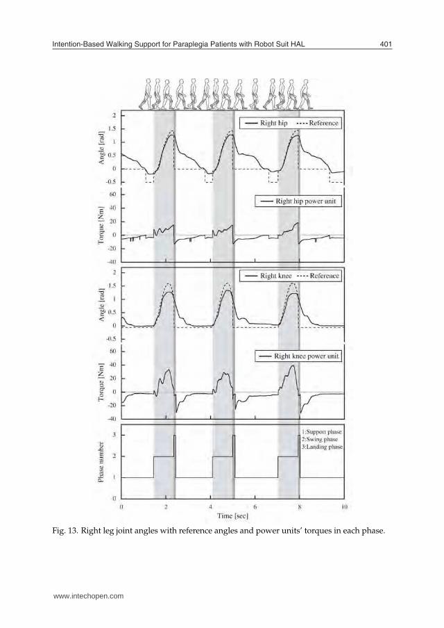
Figures 10 and 11 show the FRF data and phase transitions on each leg during a walkingsupport. In both figures, one leg performs as the support leg up to a toe-off moment when theequation (6) or (8) is satisfied and then the leg performs as the swing leg for 0.9 sec and theleg begins to support his weight as the support leg from a heel-on moment when the equation(1) or (3) is satisfied shortly after the start of the landing phase. In addition, Fig. 12 showsthe FRF data on both legs and the phase transitions at the start of walking support. The FRFof the heel part is almost zero since the subject A leans on the walking frame for the sake ofsafety. On the other hand, the FRF of the toe part reflects the shift of his COG. At first, hestands on his legs with a load distribution which the right leg supports about 250 N and theleft leg supports about 350 N. After that, he shifts his COG in a direction toward his left side,and finally the right and left leg begins to perform as a swing leg and support leg, respectivelywhen the equations (5) and (6) are satisfied. HAL starts supporting the walk of the subject Asynchronizing his intentions. Figures 13 and 14 show his each joint angles, their referencesand torques of the power units during walking support. From the results of joint angles inthese figures, his hip and knee joints follow the reference angles in a almost part of time inone cycle of the supported walk. HAL supports his walk based on a healthy person’s walkas shown in Fig. 7. On the other hand, the results in a latter part of the swing phases showhis joints do not follow the references, especially knee joint on his left leg which has a severesensory trouble. The knee joint of the subject A resists the actuator of HAL since he doesnot get used to receiving the physical support. The tracking error will be small after enoughtraining for relaxation of the knee joint in the swing phase.
www.intechopen.com

Intention-Based Walking Support for Paraplegia Patients with Robot Suit HAL 397
6. CONCLUSIONS
In this chapter, we have proposed the algorithm to estimate patients’ intentions so that theHAL-5 Type-C could support a patient with paraplegia to walk. The estimation algorithmbased on the floor reaction force was investigated through the walking support experimentsfor a patient with a sensory paralysis on both legs. The cycle of reference walking patterns wasadjusted for the patient and the walking support based on the reference walking was achieved,synchronizing with a patient’s intentions estimated by the algorithm. We confirmed that thealgorithm successfully estimated corresponding to a patient’s intentions. However, it did notstabilize a patient’s body posture and he had to maintain his balance using a walking framewith his hands. One of our future works is to develop a stabilizing algorithm and mechanismso that his hand regains its own functions.
www.intechopen.com

Climbing and Walking Robots398
Fig. 10. Result of FRF-based intention estimation on right leg.
www.intechopen.com

Intention-Based Walking Support for Paraplegia Patients with Robot Suit HAL 399
Fig. 11. Result of FRF-based intention estimation on left leg.
www.intechopen.com

Climbing and Walking Robots400
Fig. 12. Start of walking support by intention estimation.
www.intechopen.com
Intention-Based Walking Support for Paraplegia Patients with Robot Suit HAL 401
Fig. 13. Right leg joint angles with reference angles and power units’ torques in each phase.
www.intechopen.com

Climbing and Walking Robots402
Fig. 14. Left leg joint angles with reference angles and power units’ torques in each phase.
www.intechopen.com

Intention-Based Walking Support for Paraplegia Patients with Robot Suit HAL 403
Acknowledgments
This research was partially supported by Grant-in-Aid for Scientific Research (General Re-search (A), No. 17206045, 2005-2008) from the Ministry of Education, Culture, Sports, Scienceand Technology of Japan and by Health and Labour Sciences Research Grants (No. H17-Physi-005, 2005-2007) from the Ministry of Health, Labour and Welfare of Japan.
7. REFERENCES
[1] Junpei Okamura, Hiroshi Tanaka and Yoshiyuki Sankai, EMG-based Prototype PoweredAssistive System for Walking Aid, in Proc. of Asian Symposium on Industrial Automa-tion and Robotics (ASIAR’99), Bangkok, pp.229-234 (1999).
[2] Takao Nakai, Suwoong Lee, Hiroaki Kawamoto and Yoshiyuki Sankai, Development ofPowered Assistive Leg for Walking Aid using EMG and Linux, in Proc. of Asian Sym-posium on Industrial Automation and Robotics (ASIAR’01), Bangkok, pp.295-299 (2001).
[3] Lee S. and Sankai Y., Power Assist Control for Walking Aid with HAL-3 Based on EMG andImpedance Adjustment around Knee Joint, Proc. of IEEE/RSJ International Conferenceon Intelligent Robots and Systems (IROS 2002), EPFL, Switzerland, pp.1499-1504 (2002).
[4] Jerry E. Pratt, Benjamin T. Krupp, Christopher J. Morse and Steven H. Collins, TheRoboKnee: An Exoskeleton for Enhancing Strength and Endurance During Walk-ing, in Proc. of the 2004 IEEE International Conference on Robotics and Automation (ICRA’04), New Orleans, pp.2430-2435 (2004).
[5] Takahiko Nakamura, Kazunari Saito and Kazuhiro Kosuge, Control of Wearable WalkingSupport System Based on Human-Model and GRF, Proc. of the 2005 IEEE InternationalConference on Robotics and Automation (ICRA ’05), Barcelona, pp. 4405-4410 (2005).
[6] H. Kazerooni, Ryan Steger and Lihua Huang, Hybrid Control of the Berkeley Lower Ex-tremity Exoskeleton (BLEEX), The International Journal of Robotics Research, vol. 25, pp.561-573 (2006).
[7] Ryan Steger, Sung Hoon Kim and H. Kazerooni, Control Scheme and Networked ControlArchitecture for the Berkeley Lower Extremity Exoskeleton (BLEEX), in Proc. of the2006 IEEE International Conference on Robotics and Automation (ICRA ’06), Orlando,Florida, pp. 3469-3476 (2006).
[8] Hiroaki Kawamoto and Yoshiyuki Sankai, Power Assist System HAL-3 for Gait DisorderPerson, Proc. of the 2002 International Conference on Computers Helping People with Spe-cial Needs (IC-CHP 2002), Linz, Austria, pp. 196-203 (2002).
[9] Hiroaki Kawamoto and Yoshiyuki Sankai, Power assist method based on Phase Sequenceand muscle force condition for HAL, Advanced Robotics, vol. 19, No. 7, pp. 717-734(2005).
[10] Masashi SATO, Hidetaka IKEUCHI, Ryozo KATOH and Tadashi YAMASHITA, Experi-mental Analysis of Reaction Force and Motion of Center of Gravity during HumanGait Initiation (Characteristics of Transferring from Transient Phase to Steady-StatePhase), Trans. JSME (Series C), Vol.59, No.566, pp.3101-3107 (1993). (in Japanese)
[11] H. Ikeuchi, K. Shinkoda, R. Katoh, M.Sato, T. Yamashita, Analysis of Human TransientWalking by Wavelet Transform, Proc. of The Third International Symposium on ArtificialLife and Robotics, Beppu, Japan, pp.695-698 (1998).
[12] Suzuki K., Kawamura Y., Hayashi T., Sakurai T., Hasegawa Y. and Sankai Y., Intention-Based Walking Support for Paraplegia Patient, Proc. of the 2005 IEEE InternationalConference on Systems, Man and Cybernetics (SMC2005), Hawaii, pp.2707-2713 (2005).
www.intechopen.com

Climbing and Walking Robots404
Appendix A
The PD gains of swing leg control krh, klh, k̂rh, k̂lh, krk, klk, k̂rk and k̂lk (see equations (16)) weredesigned in preliminary experiments. In this appendix section, proportional gains for the hipjoints krh and klh are expressed by k
∗h, and proportional gains for the knee joints krk and klk
are expressed by k∗k for convenience of explanation. On the other hand, derivative gains for
the hip joints k̂rh and k̂lh are expressed by k̂∗h, and derivative gains for the knee joints k̂rk
and k̂lk are expressed by k̂∗k. Figure 15 shows experimental environments, where one leg
can swing freely and the other leg supports a subject’s weight. At first, hip or knee joint iscontrolled by the PD feedback control to examine the frequency response. The reference jointangle patterns are expressed by sine function with seven different frequencies, ranging from0.1 to 3.0 Hz, and with 1.0 rad peak-to-peak amplitude. Five different PD gains, ranging thatthe proportional gain is from 20.0 to 200.0 and the derivative gain is from 0.02 to 0.20, aretested. Figures 16 and 18 show the frequency responses of hip and knee joints on Bode plot.
Fig. 15. Experimental settings for each joint frequency response. A subject with the robot suitHAL stands inside a frame with one leg on a raised block so that the other leg can swing freely.The subject are asked to keep the upper body upright and completely relax the leg to followreference joint motions produced by the HAL’s power units. Two sine curves in the figureshow the reference joint angle patterns on each joint.
Then, a unit step response of each joint is examined with six different PD gains. Figures 17 and19 show the responses of hip and knee joints. From the viewpoint of amplitude characteristic,resonance frequency and phase shift on the hip joint shown in Fig. 16, the sufficient responsecould be obtained when the range that k
∗h was from 100.0 to 200.0 and k̂∗h was from 0.10 to
0.20 at less than 0.5 Hz, which equaled leg swing frequency in this walking support. Besides,Figure 17 shows little overshoot and sufficient convergence at the proportional gain of k
∗h =100.0 and the derivative gain of k̂
∗h = 0.10 for the unit step response. In consideration of thoseresults, we set the hip joint feedback gains k
∗h and k̂∗h equaled 100.0 and 0.10 in the actual
walking supports. In the same way, the sufficient response was observed when the range thatk∗k was from 100.0 to 200.0 and k̂
∗k was from 0.10 to 0.20 at less than 1.0 Hz on the knee joint,
www.intechopen.com

Intention-Based Walking Support for Paraplegia Patients with Robot Suit HAL 405
Fig. 16. Frequency response of hip joint shown in Bode plot. Upper graph and lower one showamplitude characteristic and phase characteristic, respectively. Line No. 1 is a characteristiccurve in a case of “k
∗h = 20.0 and k̂∗h = 0.02”. Similarly, line No. 2, No. 3, No. 4 and No.
5 show that of “k∗h = 50.0 and k̂
∗h = 0.05”, “k∗h = 100.0 and k̂
∗h = 0.10”, “k∗h = 150.0 and
k̂∗h = 0.15” and “k
∗h = 200.0 and k̂∗h = 0.20”, respectively. The all five lines are drawn using
a cubic spline curve in order to express the correspondence with seven points in the same setof feedback gains. They therefore interpolate the experimental data and would not preciselyexpress the real values.
as shown in Fig. 18. We also set the knee joint feedback gains of 100.0 and 0.10 from theviewpoint of overshoot and oscillation on the step response, as shown in Fig. 19.
www.intechopen.com

Climbing and Walking Robots406
Fig. 17. Step responses of hip joint on six kinds of feedback gains (PD gains). Dashed linesand solid lines in the graphs show step inputs and actual angular variations, respectively.
www.intechopen.com

Intention-Based Walking Support for Paraplegia Patients with Robot Suit HAL 407
Fig. 18. Frequency response of knee joint shown in Bode plot. Upper graph and lower oneshow amplitude characteristic and phase characteristic, respectively. Line No. 1 is a character-istic curve in a case of “k
∗k = 20.0 and k̂∗k = 0.02”. Similarly, line No. 2, No. 3, No. 4 and No.
5 show that of “k∗k = 50.0 and k̂
∗k = 0.05”, “k∗k = 100.0 and k̂
∗k = 0.10”, “k∗k = 150.0 and
k̂∗k = 0.15” and “k
∗k = 200.0 and k̂∗k = 0.20”, respectively. The all five lines are drawn using
a cubic spline curve in order to express the correspondence with seven points in the same setof feedback gains. They therefore interpolate the experimental data and would not preciselyexpress the real values.
www.intechopen.com

Climbing and Walking Robots408
Fig. 19. Step responses of knee joints on six kinds of feedback gains (PD gains). Dashed linesand solid lines in the graphs shows step inputs and actual angular variations, respectively.
www.intechopen.com

Climbing and Walking RobotsEdited by Behnam Miripour
ISBN 978-953-307-030-8Hard cover, 508 pagesPublisher InTechPublished online 01, March, 2010Published in print edition March, 2010
InTech EuropeUniversity Campus STeP Ri Slavka Krautzeka 83/A 51000 Rijeka, Croatia Phone: +385 (51) 770 447 Fax: +385 (51) 686 166
InTech ChinaUnit 405, Office Block, Hotel Equatorial Shanghai No.65, Yan An Road (West), Shanghai, 200040, China
Phone: +86-21-62489820 Fax: +86-21-62489821
Nowadays robotics is one of the most dynamic fields of scientific researches. The shift of robotics researchesfrom manufacturing to services applications is clear. During the last decades interest in studying climbing andwalking robots has been increased. This increasing interest has been in many areas that most important onesof them are: mechanics, electronics, medical engineering, cybernetics, controls, and computers. Today’sclimbing and walking robots are a combination of manipulative, perceptive, communicative, and cognitiveabilities and they are capable of performing many tasks in industrial and non- industrial environments.Surveillance, planetary exploration, emergence rescue operations, reconnaissance, petrochemicalapplications, construction, entertainment, personal services, intervention in severe environments,transportation, medical and etc are some applications from a very diverse application fields of climbing andwalking robots. By great progress in this area of robotics it is anticipated that next generation climbing andwalking robots will enhance lives and will change the way the human works, thinks and makes decisions. Thisbook presents the state of the art achievments, recent developments, applications and future challenges ofclimbing and walking robots. These are presented in 24 chapters by authors throughtot the world The bookserves as a reference especially for the researchers who are interested in mobile robots. It also is useful forindustrial engineers and graduate students in advanced study.
How to referenceIn order to correctly reference this scholarly work, feel free to copy and paste the following:
Kenta Suzuki, Gouji Mito, Hiroaki Kawamoto, Yasuhisa Hasegawa and Yoshiyuki Sankai (2010). Intention-Based Walking Support for Paraplegia Patients with Robot Suit HAL, Climbing and Walking Robots, BehnamMiripour (Ed.), ISBN: 978-953-307-030-8, InTech, Available from: http://www.intechopen.com/books/climbing-and-walking-robots/intention-based-walking-support-for-paraplegia-patients-with-robot-suit-hal
www.intechopen.com

www.intechopen.com

© 2010 The Author(s). Licensee IntechOpen. This chapter is distributedunder the terms of the Creative Commons Attribution-NonCommercial-ShareAlike-3.0 License, which permits use, distribution and reproduction fornon-commercial purposes, provided the original is properly cited andderivative works building on this content are distributed under the samelicense.