Embed Size (px)
Citation preview
Intelligent lightweight design by forged transmission components Dr.-Ing. Stephan Weidel/ Dr.-Ing. Hans-Willi Raedt/ Gerhard Linder, Hirschvogel Umformtechnik GmbH, Germany; Abstract
Due to the current trend towards lightweight design in automotive industry, also the weight of
transmissions has to be reduced. An optimization of the production process is necessary as
well as the reduction of input material for economical reasons. Components produced by
forging feature high potential for lightweight design due to their excellent properties which
can be traced back to the load oriented fibre flow. Further potential for weight reduction is
provided by using hollow shafts instead of solid shafts. Various process variants based on
forging technology are presented and assessed. Another possibility for weight reduction
consists of forged gears. Thus, components may be shortened by using forged gears as no
lead-out area of the milling tool is necessary. Additionally, geometries can be produced
which can be hardly manufactured economically by machining processes. Furthermore, a
concept for burr reduction of machined running gears based on forging technology is
presented.
Various examples of series production as well as developments illustrate the potential for
lightweight design as well as the economical benefits of forging technology. New material
developments are presented within the outlook.
Kurzfassung
Aufgrund des aktuellen Trends zum Leichtbau muss bei der Getriebeherstellung mehr denn
je auf ein möglichst geringes Einbaugewicht der Einzelbauteile geachtet werden. Gleichzeitig
erfordern wirtschaftliche Aspekte eine Optimierung des Herstellprozesses sowie die
maximale Einsparung von Vormaterial. Umformtechnisch hergestellte Bauteile besitzen ein
hohes Leichtbaupotential aufgrund ihrer hervorragenden Werkstoffeigenschaften, die u.a. auf
den beanspruchungsgerechten Faserverlauf zurückzuführen sind. Weiteres Potential zur
Gewichtseinsparung besitzt die Ausführung torsionsbelasteter Wellen als Hohlteile. Es
werden verschiedene umformtechnische Prozessrouten zur wirtschaftlichen Herstellung von
Hohlteilen vorgestellt und bewertet. Leichtbaupotential ergibt sich außerdem bei der
Verwendung umformend hergestellter Verzahnungen. So können durch umgeformte
Verzahnungen Bauteile verkürzt und Geometrien hergestellt werden, die zerspanend
wirtschaftlich nicht herstellbar sind. Außerdem wird ein umformtechnisches Konzept zur
Verringerung der Gratbildung bei der spanenden Herstellung von Laufverzahnungen
vorgestellt.
Anhand verschiedener Beispiele aus Serienproduktion wie aus Entwicklung werden das
Leichtbaupotential sowie die wirtschaftlichen Vorteile der Massivumformung dargestellt. In
einem Ausblick werden neue Werkstoffentwicklungen vorgestellt.
1. Introduction
Due to the ongoing discussion on climate change, automotive industry faces essential
challenges. The necessary reduction of CO2 emission requires consistent lightweight design
in the whole vehicle. Likewise, the trend towards electric cars needs lightweight design for
compensating the additional weight of battery systems. Thus, the need for weight reduction
is also present regarding transmissions. Besides the design of the transmission itself, the
production technology has a significant impact on the weight saving potential of single
components. However, lightweight design can only be successful if it is accepted in the
market. This implies cost-effective solutions feasible for mass production.
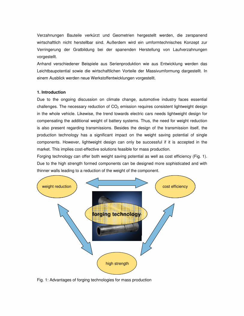
Forging technology can offer both weight saving potential as well as cost efficiency (Fig. 1).
Due to the high strength formed components can be designed more sophisticated and with
thinner walls leading to a reduction of the weight of the component.
weight reduction cost efficiency
high strength
forging technology
weight reductionweight reduction cost efficiencycost efficiency
high strength
forging technology
Fig. 1: Advantages of forging technologies for mass production
2. Potential for lightweight design by forging
Due to excellent material properties which allow smaller wall thicknesses, forged
components exhibit a huge potential for lightweight design. In combination with specific heat
treatment processes, the material may be adapted to optimally meet the demands of the
component. Therefore, material, component design and forging temperatures have to be
coordinated well for achieving ideal component properties and cost efficient production.
One reason for superb mechanical properties of forged components is the fibre flow which is
aligned with the geometry of the component. Schuster et al. [1] revealed by various etching
methods that the fibre flow is determined by the orientation of elongated inclusions,
especially manganese sulphides MnS. While the tensile strength and the yield strength are
hardly influenced by the orientation of manganese sulphide inclusions [2], a positive effect on
the impact work as well as the fatigue strength can be observed in case of longitudinal
orientated manganese sulphides. Cyril et al. [3] observed that the impact work of a 42CrMo4
with a hardness of 50 HRC is reduced by 74 % from longitudinal to transverse orientation of
manganese sulfides. For low sulphur contents, the impact work is reduced by 40 %. Schuster
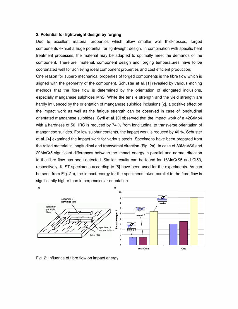
et al. [4] examined the impact work for various steels. Specimens have been prepared from
the rolled material in longitudinal and transversal direction (Fig. 2a). In case of 30MnVS6 and
20MnCr5 significant differences between the impact energy in parallel and normal direction
to the fibre flow has been detected. Similar results can be found for 16MnCrS5 and Cf53,
respectively. KLST specimens according to [5] have been used for the experiments. As can
be seen from Fig. 2b), the impact energy for the specimens taken parallel to the fibre flow is
significantly higher than in perpendicular orientation.
0
1
2
3
4
5
6
7
8
9
10
16MnCrS5 Cf53
Imp
act
en
erg
y/ J
normal 1
normal 2
parallel
specimenparallel to
fibre
MnS-fibre
specimen 2 normal to fibre
specimen 1 normal to fibre
a) b)
0
1
2
3
4
5
6
7
8
9
10
16MnCrS5 Cf53
Imp
act
en
erg
y/ J
normal 1
normal 2
parallel
0
1
2
3
4
5
6
7
8
9
10
16MnCrS5 Cf53
Imp
act
en
erg
y/ J
normal 1normal 1normal 1
normal 2normal 2normal 2
parallelparallelparallel
specimenparallel to
fibre
MnS-fibre
specimen 2 normal to fibre
specimen 1 normal to fibre
a) b)
Fig. 2: Influence of fibre flow on impact energy
Regarding fatigue strength, e.g. investigations of Furuya et al. [6] exhibit a reduction from
longitudinal to transverse direction of 50 % for a quenched and tempered spring steel.
Eventually, it can be concluded that the fibre flow has a significant influence on the
mechanical properties of the component. Especially, mechanical properties at dynamic
conditions can be significantly affected by the orientation of the fibre flow. Thus, forging
processes which lead to a fibre flow aligned with the geometry of the component, improve
the mechanical properties of the parts.
3. Hollow shafts
The application of hollow transmission shafts is increasing due to the rising demand for
weight reduction and due to the increasing demand for double clutch transmissions typically
using concentrically running shafts. Hollow design of transmission shafts exhibits a
significant weight reduction potential as the mechanical properties like torsional stiffness are
hardly influenced by the core material. Thus, from solid to hollow design of shafts in
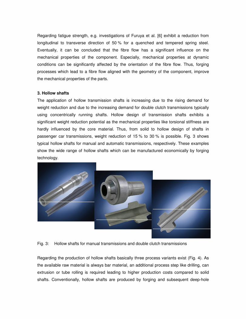
passenger car transmissions, weight reduction of 15 % to 30 % is possible. Fig. 3 shows
typical hollow shafts for manual and automatic transmissions, respectively. These examples
show the wide range of hollow shafts which can be manufactured economically by forging
technology.
Fig. 3: Hollow shafts for manual transmissions and double clutch transmissions
Regarding the production of hollow shafts basically three process variants exist (Fig. 4). As
the available raw material is always bar material, an additional process step like drilling, can
extrusion or tube rolling is required leading to higher production costs compared to solid
shafts. Conventionally, hollow shafts are produced by forging and subsequent deep-hole
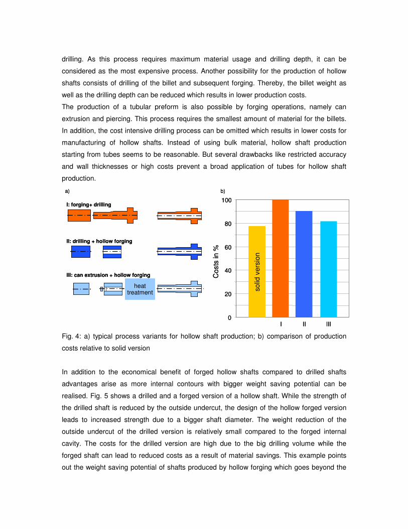
drilling. As this process requires maximum material usage and drilling depth, it can be
considered as the most expensive process. Another possibility for the production of hollow
shafts consists of drilling of the billet and subsequent forging. Thereby, the billet weight as
well as the drilling depth can be reduced which results in lower production costs.
The production of a tubular preform is also possible by forging operations, namely can
extrusion and piercing. This process requires the smallest amount of material for the billets.
In addition, the cost intensive drilling process can be omitted which results in lower costs for
manufacturing of hollow shafts. Instead of using bulk material, hollow shaft production
starting from tubes seems to be reasonable. But several drawbacks like restricted accuracy
and wall thicknesses or high costs prevent a broad application of tubes for hollow shaft
production.
heattreatment
Costs
in %
I: forging+ drilling
II: drilling + hollow forging
III: can extrusion + hollow forging
0
20
40
60
80
100
I II III
so
lid v
ers
ion
a) b)
heattreatment
heattreatment
Costs
in %
I: forging+ drilling
II: drilling + hollow forging
III: can extrusion + hollow forging
0
20
40
60
80
100
I II III
so
lid v
ers
ion
a) b)
Fig. 4: a) typical process variants for hollow shaft production; b) comparison of production
costs relative to solid version
In addition to the economical benefit of forged hollow shafts compared to drilled shafts
advantages arise as more internal contours with bigger weight saving potential can be
realised. Fig. 5 shows a drilled and a forged version of a hollow shaft. While the strength of
the drilled shaft is reduced by the outside undercut, the design of the hollow forged version
leads to increased strength due to a bigger shaft diameter. The weight reduction of the
outside undercut of the drilled version is relatively small compared to the forged internal
cavity. The costs for the drilled version are high due to the big drilling volume while the
forged shaft can lead to reduced costs as a result of material savings. This example points
out the weight saving potential of shafts produced by hollow forging which goes beyond the
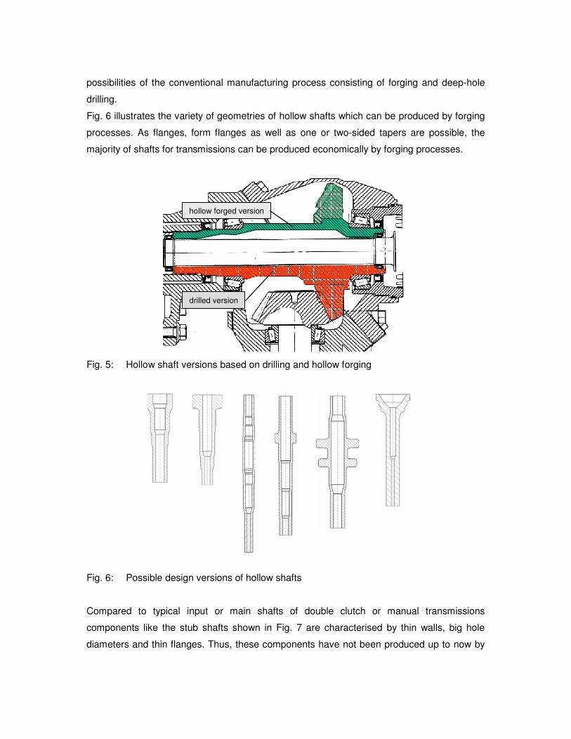
possibilities of the conventional manufacturing process consisting of forging and deep-hole
drilling.
Fig. 6 illustrates the variety of geometries of hollow shafts which can be produced by forging
processes. As flanges, form flanges as well as one or two-sided tapers are possible, the
majority of shafts for transmissions can be produced economically by forging processes.
hollow forged version
drilled version
hollow forged version
drilled version
Fig. 5: Hollow shaft versions based on drilling and hollow forging
Fig. 6: Possible design versions of hollow shafts
Compared to typical input or main shafts of double clutch or manual transmissions
components like the stub shafts shown in Fig. 7 are characterised by thin walls, big hole
diameters and thin flanges. Thus, these components have not been produced up to now by
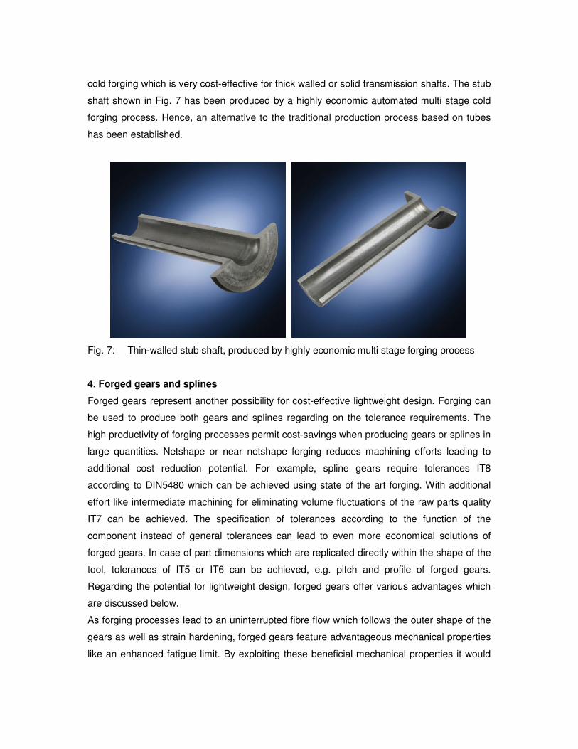
cold forging which is very cost-effective for thick walled or solid transmission shafts. The stub
shaft shown in Fig. 7 has been produced by a highly economic automated multi stage cold
forging process. Hence, an alternative to the traditional production process based on tubes
has been established.
Fig. 7: Thin-walled stub shaft, produced by highly economic multi stage forging process
4. Forged gears and splines
Forged gears represent another possibility for cost-effective lightweight design. Forging can
be used to produce both gears and splines regarding on the tolerance requirements. The
high productivity of forging processes permit cost-savings when producing gears or splines in
large quantities. Netshape or near netshape forging reduces machining efforts leading to
additional cost reduction potential. For example, spline gears require tolerances IT8
according to DIN5480 which can be achieved using state of the art forging. With additional
effort like intermediate machining for eliminating volume fluctuations of the raw parts quality
IT7 can be achieved. The specification of tolerances according to the function of the
component instead of general tolerances can lead to even more economical solutions of
forged gears. In case of part dimensions which are replicated directly within the shape of the
tool, tolerances of IT5 or IT6 can be achieved, e.g. pitch and profile of forged gears.
Regarding the potential for lightweight design, forged gears offer various advantages which
are discussed below.
As forging processes lead to an uninterrupted fibre flow which follows the outer shape of the
gears as well as strain hardening, forged gears feature advantageous mechanical properties
like an enhanced fatigue limit. By exploiting these beneficial mechanical properties it would
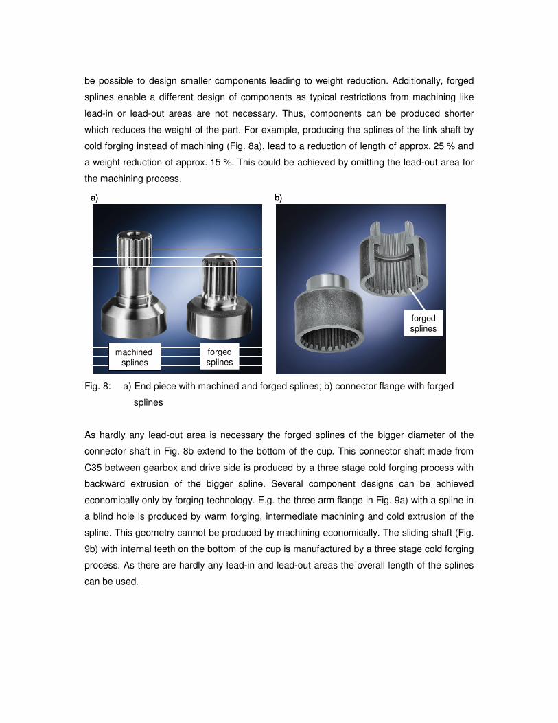
be possible to design smaller components leading to weight reduction. Additionally, forged
splines enable a different design of components as typical restrictions from machining like
lead-in or lead-out areas are not necessary. Thus, components can be produced shorter
which reduces the weight of the part. For example, producing the splines of the link shaft by
cold forging instead of machining (Fig. 8a), lead to a reduction of length of approx. 25 % and
a weight reduction of approx. 15 %. This could be achieved by omitting the lead-out area for
the machining process.
machined
splines
forged
splines
a) b)
forged
splines
machined
splines
forged
splinesmachined
splines
forged
splines
a) b)
forged
splines
forged
splines
Fig. 8: a) End piece with machined and forged splines; b) connector flange with forged
splines
As hardly any lead-out area is necessary the forged splines of the bigger diameter of the
connector shaft in Fig. 8b extend to the bottom of the cup. This connector shaft made from
C35 between gearbox and drive side is produced by a three stage cold forging process with
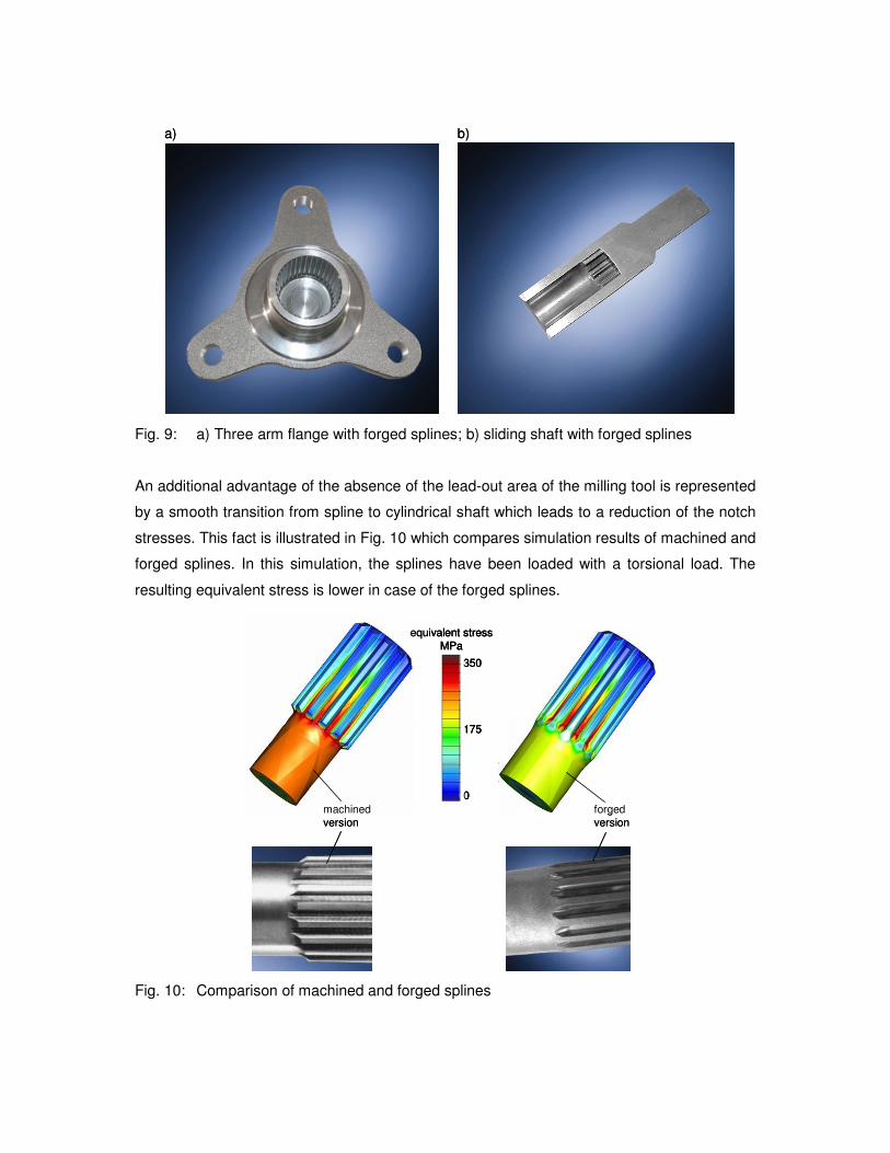
backward extrusion of the bigger spline. Several component designs can be achieved
economically only by forging technology. E.g. the three arm flange in Fig. 9a) with a spline in
a blind hole is produced by warm forging, intermediate machining and cold extrusion of the
spline. This geometry cannot be produced by machining economically. The sliding shaft (Fig.
9b) with internal teeth on the bottom of the cup is manufactured by a three stage cold forging
process. As there are hardly any lead-in and lead-out areas the overall length of the splines
can be used.
a) b)a) b)
Fig. 9: a) Three arm flange with forged splines; b) sliding shaft with forged splines
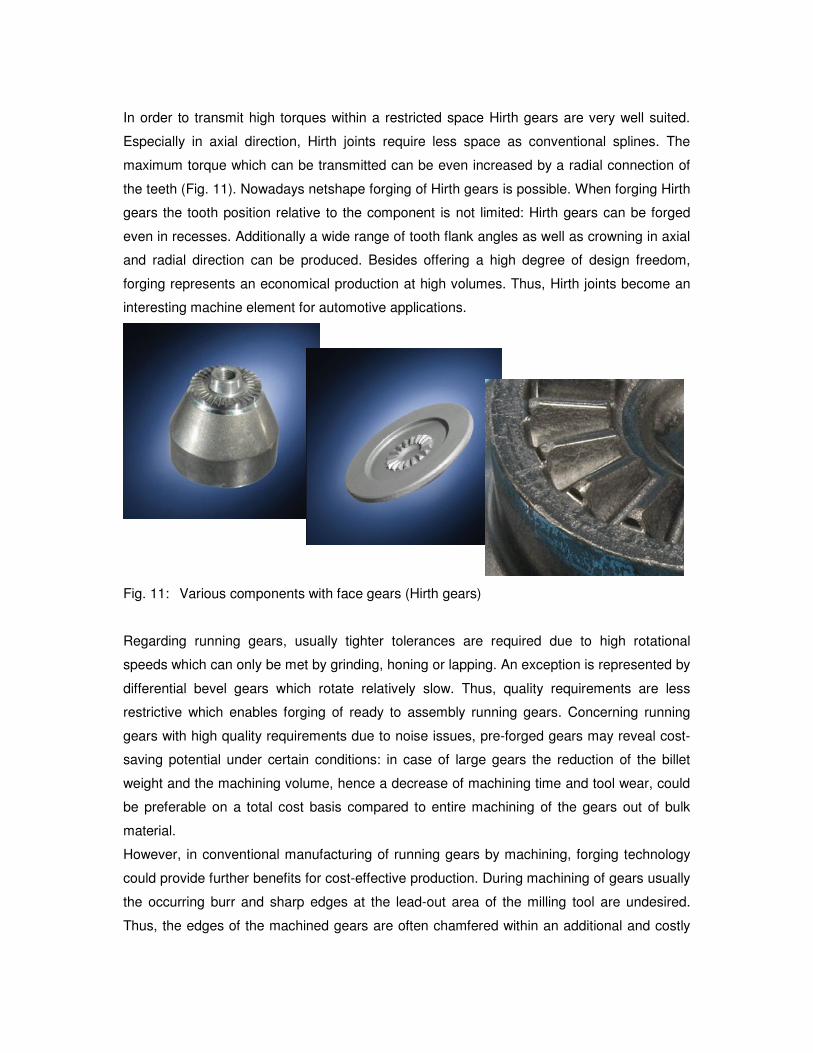
An additional advantage of the absence of the lead-out area of the milling tool is represented
by a smooth transition from spline to cylindrical shaft which leads to a reduction of the notch
stresses. This fact is illustrated in Fig. 10 which compares simulation results of machined and
forged splines. In this simulation, the splines have been loaded with a torsional load. The
resulting equivalent stress is lower in case of the forged splines.
350
175
0
equivalent stress
MPa
machined
version
forged
version
350
175
0
equivalent stress
MPa
350
175
0
equivalent stress
MPa
machined
version
forged
version
Fig. 10: Comparison of machined and forged splines
In order to transmit high torques within a restricted space Hirth gears are very well suited.
Especially in axial direction, Hirth joints require less space as conventional splines. The
maximum torque which can be transmitted can be even increased by a radial connection of
the teeth (Fig. 11). Nowadays netshape forging of Hirth gears is possible. When forging Hirth
gears the tooth position relative to the component is not limited: Hirth gears can be forged
even in recesses. Additionally a wide range of tooth flank angles as well as crowning in axial
and radial direction can be produced. Besides offering a high degree of design freedom,
forging represents an economical production at high volumes. Thus, Hirth joints become an
interesting machine element for automotive applications.
Fig. 11: Various components with face gears (Hirth gears)
Regarding running gears, usually tighter tolerances are required due to high rotational
speeds which can only be met by grinding, honing or lapping. An exception is represented by
differential bevel gears which rotate relatively slow. Thus, quality requirements are less
restrictive which enables forging of ready to assembly running gears. Concerning running
gears with high quality requirements due to noise issues, pre-forged gears may reveal cost-
saving potential under certain conditions: in case of large gears the reduction of the billet
weight and the machining volume, hence a decrease of machining time and tool wear, could
be preferable on a total cost basis compared to entire machining of the gears out of bulk
material.
However, in conventional manufacturing of running gears by machining, forging technology
could provide further benefits for cost-effective production. During machining of gears usually
the occurring burr and sharp edges at the lead-out area of the milling tool are undesired.
Thus, the edges of the machined gears are often chamfered within an additional and costly
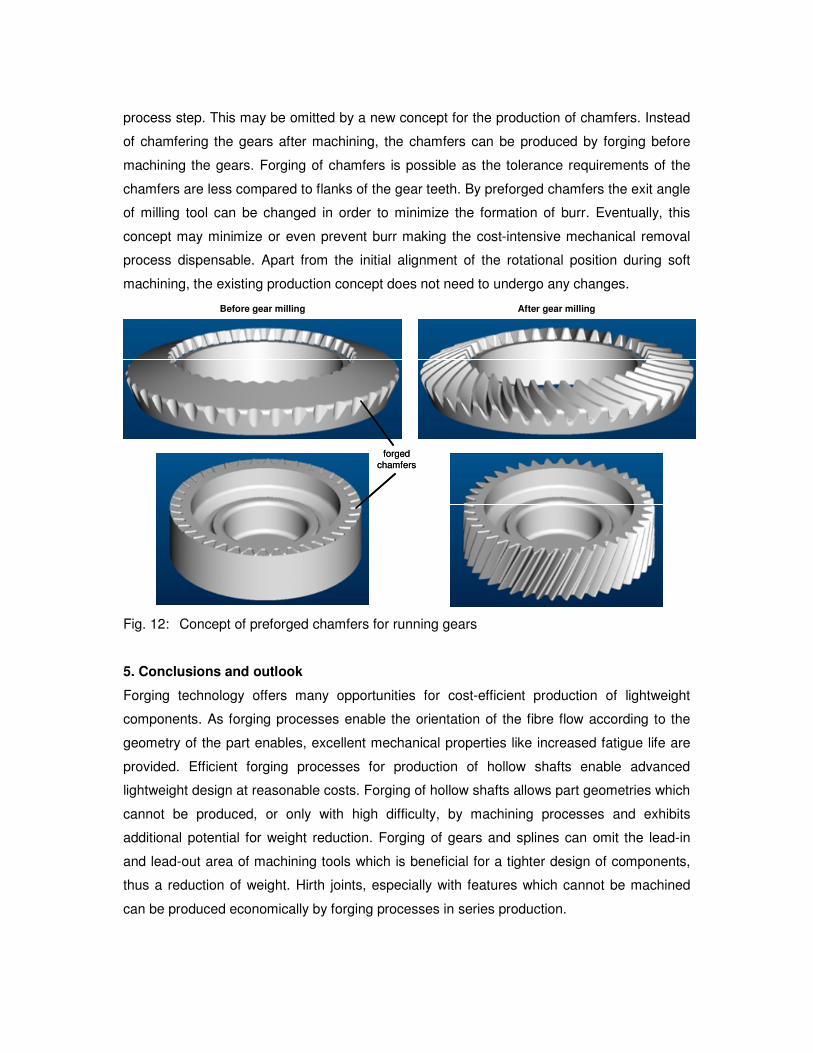
process step. This may be omitted by a new concept for the production of chamfers. Instead
of chamfering the gears after machining, the chamfers can be produced by forging before
machining the gears. Forging of chamfers is possible as the tolerance requirements of the
chamfers are less compared to flanks of the gear teeth. By preforged chamfers the exit angle
of milling tool can be changed in order to minimize the formation of burr. Eventually, this
concept may minimize or even prevent burr making the cost-intensive mechanical removal
process dispensable. Apart from the initial alignment of the rotational position during soft
machining, the existing production concept does not need to undergo any changes.
forged
chamfers
Before gear milling After gear milling
forged
chamfers
Before gear milling After gear milling
Fig. 12: Concept of preforged chamfers for running gears
5. Conclusions and outlook
Forging technology offers many opportunities for cost-efficient production of lightweight
components. As forging processes enable the orientation of the fibre flow according to the
geometry of the part enables, excellent mechanical properties like increased fatigue life are
provided. Efficient forging processes for production of hollow shafts enable advanced
lightweight design at reasonable costs. Forging of hollow shafts allows part geometries which
cannot be produced, or only with high difficulty, by machining processes and exhibits
additional potential for weight reduction. Forging of gears and splines can omit the lead-in
and lead-out area of machining tools which is beneficial for a tighter design of components,
thus a reduction of weight. Hirth joints, especially with features which cannot be machined
can be produced economically by forging processes in series production.
For the development of innovative and excellent products, an early interaction between
customer and supplier is necessary. Thus, the Hirschvogel Automotive Group provides its
longtime experience to all customers worldwide and offers assistance from the first design
concept up to assembly-ready components in large scale production. Various new
developments support to supply the customers with innovative and excellent products. For
example, a new steel grade H2 has been developed. The steel H2 offers high hardenability
which is achieved by low cost alloying elements. Thus, H2 steel could be a cost-efficient
alternative to 18CrNiMo7-6 or other high-alloyed case hardening steels. While fundamental
investigations have been accomplished, the development of a series production part in
cooperation with customers is necessary to activate the economic potential of H2 steel.
References
[1] Schuster, A.; Raedt, H.-W.; Tekkaya, A.E.: The Fibre Flow in Steel before and after
Cold Upsetting. In: Proc. of 43rd Plenary Meeting of the International Cold Forging
Group ICFG. 12-15 Sept. 2010, Darmstadt, Germany
[2] Golze, N.; Schoch, H.: Faserverlauf beeinflusst Dauerfestigkeit, Industrie Anzeiger 1/2 ,
111. Jg., pp. 28-30, 1989
[3] Cyril, N.; Fatemi, A.; Cryderman, B.: Effects of Sulfur Level and Anisotropy of Sulfides
Inclusions on Tensile, Impact, and Fatigue Properties of SAE4140 Steel, SAE Paper
No. 2008-01-0434, SAE World Congress & Exhibition, Detroit, MI, April 2008
[4] Schuster, A.; Raedt, H.-W.; Tekkaya, A.E.: Der Faserverlauf in Warm gewalztem Stahl
und dessen Auswirkungen auf mechanische Bauteileigenschaften. Planneralm 2011
[5] DIN 50115: Prüfung metallischer Werkstoffe; Kerbschlagbiegeversuch; Besondere
Probenform und Auswerteverfahren, 1991, Berlin, Beuth Verlag
[6] Furuya, Y.; Matsuoka, S., Abe, T.: Inclusion Controlled Fatigue Properties of 1800 MPa
-Class Spring Steel, Metallurgical and Materials Transactions A, Vol. 35A, No.12, pp.
3737-3744, Dec. 2004