Embed Size (px)
Citation preview

Intel NetStructure® Digital Network Interface BoardsConfiguration Guide
May 2006
05-2474-002

Digital Network Interface Boards Configuration Guide – May 2006
INFORMATION IN THIS DOCUMENT IS PROVIDED IN CONNECTION WITH INTEL® PRODUCTS. NO LICENSE, EXPRESS OR IMPLIED, BY ESTOPPEL OR OTHERWISE, TO ANY INTELLECTUAL PROPERTY RIGHTS IS GRANTED BY THIS DOCUMENT. EXCEPT AS PROVIDED IN INTEL'S TERMS AND CONDITIONS OF SALE FOR SUCH PRODUCTS, INTEL ASSUMES NO LIABILITY WHATSOEVER, AND INTEL DISCLAIMS ANY EXPRESS OR IMPLIED WARRANTY, RELATING TO SALE AND/OR USE OF INTEL PRODUCTS INCLUDING LIABILITY OR WARRANTIES RELATING TO FITNESS FOR A PARTICULAR PURPOSE, MERCHANTABILITY, OR INFRINGEMENT OF ANY PATENT, COPYRIGHT OR OTHER INTELLECTUAL PROPERTY RIGHT. Intel products are not intended for use in medical, life saving, life sustaining, critical control or safety systems, or nuclear facility applications.
Intel may make changes to specifications and product descriptions at any time, without notice.
This Intel NetStructure® Digital Network Interface Boards Configuration Guide as well as the software described in it is furnished under license and may only be used or copied in accordance with the terms of the license. The information in this manual is furnished for informational use only, is subject to change without notice, and should not be construed as a commitment by Intel Corporation. Intel Corporation assumes no responsibility or liability for any errors or inaccuracies that may appear in this document or any software that may be provided in association with this document.
Except as permitted by such license, no part of this document may be reproduced, stored in a retrieval system, or transmitted in any form or by any means without the express written consent of Intel Corporation.
Copyright © 2005-2006, Intel Corporation
Dialogic, Intel, Intel logo, and Intel NetStructure are trademarks or registered trademarks of Intel Corporation or its subsidiaries in the United States and other countries.
* Other names and brands may be claimed as the property of others.
Publication Date: May 2006
Document Number: 05-2474-002
Intel 1515 Route 10Parsippany, NJ 07054
For Technical Support, visit the Intel Telecom Support Resources website at:http://developer.intel.com/design/telecom/support
For Products and Services Information, visit the Intel Telecom and Compute Products website at:http://www.intel.com/design/network/products/telecom
For Sales Offices and other contact information, visit the Buy Telecom Products page at:http://www.intel.com/buy/networking/telecom.htm

Digital Network Interface Boards Configuration Guide – May 2006 3
Contents
Revision History . . . . . . . . . . . . . . . . . . . . . . . . . . . . . . . . . . . . . . . . . . . . . . . . . . . . . . . . . . . . . . 7
About This Publication . . . . . . . . . . . . . . . . . . . . . . . . . . . . . . . . . . . . . . . . . . . . . . . . . . . . . . . . 9Purpose . . . . . . . . . . . . . . . . . . . . . . . . . . . . . . . . . . . . . . . . . . . . . . . . . . . . . . . . . . . . . . . . 9Applicability . . . . . . . . . . . . . . . . . . . . . . . . . . . . . . . . . . . . . . . . . . . . . . . . . . . . . . . . . . . . . 9Intended Audience. . . . . . . . . . . . . . . . . . . . . . . . . . . . . . . . . . . . . . . . . . . . . . . . . . . . . . . . 9How to Use This Publication . . . . . . . . . . . . . . . . . . . . . . . . . . . . . . . . . . . . . . . . . . . . . . . . 9Related Information . . . . . . . . . . . . . . . . . . . . . . . . . . . . . . . . . . . . . . . . . . . . . . . . . . . . . . 10
1 Configuration Overview . . . . . . . . . . . . . . . . . . . . . . . . . . . . . . . . . . . . . . . . . . . . . . . . . . . . . . . 11
1.1 Major Configuration Steps . . . . . . . . . . . . . . . . . . . . . . . . . . . . . . . . . . . . . . . . . . . . . . . . . 111.2 The Configuration Process . . . . . . . . . . . . . . . . . . . . . . . . . . . . . . . . . . . . . . . . . . . . . . . . 11
2 Configuration Manager (DCM) Details . . . . . . . . . . . . . . . . . . . . . . . . . . . . . . . . . . . . . . . . . . . 15
2.1 Configuration Manager (DCM). . . . . . . . . . . . . . . . . . . . . . . . . . . . . . . . . . . . . . . . . . . . . . 152.2 TDM Bus Parameters . . . . . . . . . . . . . . . . . . . . . . . . . . . . . . . . . . . . . . . . . . . . . . . . . . . . 182.3 Bridge Device Parameters. . . . . . . . . . . . . . . . . . . . . . . . . . . . . . . . . . . . . . . . . . . . . . . . . 192.4 Bridge Controller Parameters . . . . . . . . . . . . . . . . . . . . . . . . . . . . . . . . . . . . . . . . . . . . . . 202.5 Configuration File Sets . . . . . . . . . . . . . . . . . . . . . . . . . . . . . . . . . . . . . . . . . . . . . . . . . . . 212.6 Media Loads . . . . . . . . . . . . . . . . . . . . . . . . . . . . . . . . . . . . . . . . . . . . . . . . . . . . . . . . . . . 22
2.6.1 Features Supported . . . . . . . . . . . . . . . . . . . . . . . . . . . . . . . . . . . . . . . . . . . . . . . 222.6.2 Fixed and Flexible Routing Configuration. . . . . . . . . . . . . . . . . . . . . . . . . . . . . . . 23
2.7 CT Bus (TDM) Clocking. . . . . . . . . . . . . . . . . . . . . . . . . . . . . . . . . . . . . . . . . . . . . . . . . . . 232.7.1 Primary Clock Fallback . . . . . . . . . . . . . . . . . . . . . . . . . . . . . . . . . . . . . . . . . . . . . 23
2.8 HMP Clocking and Fallback. . . . . . . . . . . . . . . . . . . . . . . . . . . . . . . . . . . . . . . . . . . . . . . . 24
3 CONFIG File Details . . . . . . . . . . . . . . . . . . . . . . . . . . . . . . . . . . . . . . . . . . . . . . . . . . . . . . . . . . 27
3.1 CONFIG File Formatting Conventions. . . . . . . . . . . . . . . . . . . . . . . . . . . . . . . . . . . . . . . . 273.2 CONFIG File Sections . . . . . . . . . . . . . . . . . . . . . . . . . . . . . . . . . . . . . . . . . . . . . . . . . . . . 283.3 [NFAS] Section . . . . . . . . . . . . . . . . . . . . . . . . . . . . . . . . . . . . . . . . . . . . . . . . . . . . . . . . . 283.4 [CHP] Section . . . . . . . . . . . . . . . . . . . . . . . . . . . . . . . . . . . . . . . . . . . . . . . . . . . . . . . . . . 293.5 [TSC] Section. . . . . . . . . . . . . . . . . . . . . . . . . . . . . . . . . . . . . . . . . . . . . . . . . . . . . . . . . . . 30
4 Configuration Procedures . . . . . . . . . . . . . . . . . . . . . . . . . . . . . . . . . . . . . . . . . . . . . . . . . . . . . 33
4.1 Assumptions and Prerequisites . . . . . . . . . . . . . . . . . . . . . . . . . . . . . . . . . . . . . . . . . . . . . 334.2 Order of Procedures . . . . . . . . . . . . . . . . . . . . . . . . . . . . . . . . . . . . . . . . . . . . . . . . . . . . . 344.3 Starting the Configuration Manager (DCM) . . . . . . . . . . . . . . . . . . . . . . . . . . . . . . . . . . . . 344.4 Selecting a Configuration File Set . . . . . . . . . . . . . . . . . . . . . . . . . . . . . . . . . . . . . . . . . . . 364.5 Setting the TDM Bus Clock Source . . . . . . . . . . . . . . . . . . . . . . . . . . . . . . . . . . . . . . . . . . 384.6 Modifying Bridge Device Parameters . . . . . . . . . . . . . . . . . . . . . . . . . . . . . . . . . . . . . . . . 394.7 Modifying Bridge Controller Parameters . . . . . . . . . . . . . . . . . . . . . . . . . . . . . . . . . . . . . . 414.8 Setting the Bus Companding Method . . . . . . . . . . . . . . . . . . . . . . . . . . . . . . . . . . . . . . . . 424.9 Modifying Other DCM Property Sheet Parameters . . . . . . . . . . . . . . . . . . . . . . . . . . . . . . 434.10 Modifying the FCD File Parameters. . . . . . . . . . . . . . . . . . . . . . . . . . . . . . . . . . . . . . . . . . 44
4.10.1 Editing the CONFIG File . . . . . . . . . . . . . . . . . . . . . . . . . . . . . . . . . . . . . . . . . . . . 444.10.2 Generating the FCD File . . . . . . . . . . . . . . . . . . . . . . . . . . . . . . . . . . . . . . . . . . . . 45

4 Digital Network Interface Boards Configuration Guide – May 2006
Contents
4.11 Configuring the Global Call CDP File . . . . . . . . . . . . . . . . . . . . . . . . . . . . . . . . . . . . . . . . . 454.12 Initializing the System. . . . . . . . . . . . . . . . . . . . . . . . . . . . . . . . . . . . . . . . . . . . . . . . . . . . . 464.13 Reconfiguring the System. . . . . . . . . . . . . . . . . . . . . . . . . . . . . . . . . . . . . . . . . . . . . . . . . . 46
5 Echo Cancellation . . . . . . . . . . . . . . . . . . . . . . . . . . . . . . . . . . . . . . . . . . . . . . . . . . . . . . . . . . . . 49
5.1 Echo Cancellation Background Information . . . . . . . . . . . . . . . . . . . . . . . . . . . . . . . . . . . . 495.1.1 Overview . . . . . . . . . . . . . . . . . . . . . . . . . . . . . . . . . . . . . . . . . . . . . . . . . . . . . . . . 495.1.2 Acoustic Echo . . . . . . . . . . . . . . . . . . . . . . . . . . . . . . . . . . . . . . . . . . . . . . . . . . . . 495.1.3 Electrical Echo . . . . . . . . . . . . . . . . . . . . . . . . . . . . . . . . . . . . . . . . . . . . . . . . . . . . 50
5.2 Echo Cancellation Features . . . . . . . . . . . . . . . . . . . . . . . . . . . . . . . . . . . . . . . . . . . . . . . . 515.3 Using Echo Cancellation. . . . . . . . . . . . . . . . . . . . . . . . . . . . . . . . . . . . . . . . . . . . . . . . . . . 525.4 Configuring Echo Cancellation . . . . . . . . . . . . . . . . . . . . . . . . . . . . . . . . . . . . . . . . . . . . . . 53
5.4.1 Echo Cancellation on IP Media Devices . . . . . . . . . . . . . . . . . . . . . . . . . . . . . . . . 535.4.2 Echo Cancellation on Voice Devices . . . . . . . . . . . . . . . . . . . . . . . . . . . . . . . . . . . 545.4.3 Echo Cancellation on Conferencing Devices. . . . . . . . . . . . . . . . . . . . . . . . . . . . . 555.4.4 Echo Cancellation on CSP/Voice Devices. . . . . . . . . . . . . . . . . . . . . . . . . . . . . . . 56
5.5 Echo Cancellation Sample Scenarios. . . . . . . . . . . . . . . . . . . . . . . . . . . . . . . . . . . . . . . . . 565.5.1 DTI and IP Gateway Example . . . . . . . . . . . . . . . . . . . . . . . . . . . . . . . . . . . . . . . . 575.5.2 DTI and IP Conferencing Example . . . . . . . . . . . . . . . . . . . . . . . . . . . . . . . . . . . . 575.5.3 DTI and CSP/Voice Example. . . . . . . . . . . . . . . . . . . . . . . . . . . . . . . . . . . . . . . . . 585.5.4 DTI and Voice Example . . . . . . . . . . . . . . . . . . . . . . . . . . . . . . . . . . . . . . . . . . . . . 585.5.5 IP and IP Connection Example . . . . . . . . . . . . . . . . . . . . . . . . . . . . . . . . . . . . . . . 595.5.6 IP and CSP/Voice Example . . . . . . . . . . . . . . . . . . . . . . . . . . . . . . . . . . . . . . . . . . 595.5.7 IP and Voice Example . . . . . . . . . . . . . . . . . . . . . . . . . . . . . . . . . . . . . . . . . . . . . . 59
6 DCM Parameter Reference . . . . . . . . . . . . . . . . . . . . . . . . . . . . . . . . . . . . . . . . . . . . . . . . . . . . . 61
6.1 Bridge Controller Property Sheet . . . . . . . . . . . . . . . . . . . . . . . . . . . . . . . . . . . . . . . . . . . . 616.2 Bridge Device Configuration Property Sheet . . . . . . . . . . . . . . . . . . . . . . . . . . . . . . . . . . . 626.3 Driver Property Sheet . . . . . . . . . . . . . . . . . . . . . . . . . . . . . . . . . . . . . . . . . . . . . . . . . . . . . 666.4 Logical Property Sheet . . . . . . . . . . . . . . . . . . . . . . . . . . . . . . . . . . . . . . . . . . . . . . . . . . . . 686.5 Misc Property Sheet . . . . . . . . . . . . . . . . . . . . . . . . . . . . . . . . . . . . . . . . . . . . . . . . . . . . . . 696.6 Physical Property Sheet . . . . . . . . . . . . . . . . . . . . . . . . . . . . . . . . . . . . . . . . . . . . . . . . . . . 736.7 TDM Bus Configuration Property Sheet . . . . . . . . . . . . . . . . . . . . . . . . . . . . . . . . . . . . . . . 776.8 Trunk Configuration Property Sheet . . . . . . . . . . . . . . . . . . . . . . . . . . . . . . . . . . . . . . . . . . 866.9 Version (Version Info.) Property Sheet . . . . . . . . . . . . . . . . . . . . . . . . . . . . . . . . . . . . . . . . 88
7 CONFIG File Parameter Reference . . . . . . . . . . . . . . . . . . . . . . . . . . . . . . . . . . . . . . . . . . . . . . 91
7.1 [0x2c] Echo Cancellation Parameters. . . . . . . . . . . . . . . . . . . . . . . . . . . . . . . . . . . . . . . . . 927.2 [lineAdmin.x] Parameters (Digital Voice) . . . . . . . . . . . . . . . . . . . . . . . . . . . . . . . . . . . . . . 937.3 [NFAS] Parameters. . . . . . . . . . . . . . . . . . . . . . . . . . . . . . . . . . . . . . . . . . . . . . . . . . . . . . 1017.4 [NFAS.x] Parameters . . . . . . . . . . . . . . . . . . . . . . . . . . . . . . . . . . . . . . . . . . . . . . . . . . . . 1027.5 [CCS] Parameters. . . . . . . . . . . . . . . . . . . . . . . . . . . . . . . . . . . . . . . . . . . . . . . . . . . . . . . 1047.6 [CHP] Parameters. . . . . . . . . . . . . . . . . . . . . . . . . . . . . . . . . . . . . . . . . . . . . . . . . . . . . . . 1097.7 [CHP] ISDN Protocol Variant Definitions . . . . . . . . . . . . . . . . . . . . . . . . . . . . . . . . . . . . . 1107.8 [TSC] Parameters . . . . . . . . . . . . . . . . . . . . . . . . . . . . . . . . . . . . . . . . . . . . . . . . . . . . . . . 1187.9 [TSC] defineBSet Parameters . . . . . . . . . . . . . . . . . . . . . . . . . . . . . . . . . . . . . . . . . . . . . 118
Glossary . . . . . . . . . . . . . . . . . . . . . . . . . . . . . . . . . . . . . . . . . . . . . . . . . . . . . . . . . . . . . . . . . . . 125
Numerical Index of Parameters . . . . . . . . . . . . . . . . . . . . . . . . . . . . . . . . . . . . . . . . . . . . . . . . 133
Index . . . . . . . . . . . . . . . . . . . . . . . . . . . . . . . . . . . . . . . . . . . . . . . . . . . . . . . . . . . . . . . . . . . . . . 135

Digital Network Interface Boards Configuration Guide – May 2006 5
Contents
Figures
1 DCM Main Window . . . . . . . . . . . . . . . . . . . . . . . . . . . . . . . . . . . . . . . . . . . . . . . . . . . . . . . . . . 162 Misc Property Sheet . . . . . . . . . . . . . . . . . . . . . . . . . . . . . . . . . . . . . . . . . . . . . . . . . . . . . . . . . 173 TDM Bus Configuration Property Sheet . . . . . . . . . . . . . . . . . . . . . . . . . . . . . . . . . . . . . . . . . . 184 Bridge Device Configuration Property Sheet . . . . . . . . . . . . . . . . . . . . . . . . . . . . . . . . . . . . . . . 205 Bridge Controller Property Sheet. . . . . . . . . . . . . . . . . . . . . . . . . . . . . . . . . . . . . . . . . . . . . . . . 216 Clock Fallback . . . . . . . . . . . . . . . . . . . . . . . . . . . . . . . . . . . . . . . . . . . . . . . . . . . . . . . . . . . . . . 247 Computer Name Dialog Box . . . . . . . . . . . . . . . . . . . . . . . . . . . . . . . . . . . . . . . . . . . . . . . . . . . 358 Assign Firmware File Dialog Box. . . . . . . . . . . . . . . . . . . . . . . . . . . . . . . . . . . . . . . . . . . . . . . . 379 Physical Property Sheet . . . . . . . . . . . . . . . . . . . . . . . . . . . . . . . . . . . . . . . . . . . . . . . . . . . . . . 4410 Electrical Echo and the Hybrid. . . . . . . . . . . . . . . . . . . . . . . . . . . . . . . . . . . . . . . . . . . . . . . . . . 5011 T1/E1 Gateway Example . . . . . . . . . . . . . . . . . . . . . . . . . . . . . . . . . . . . . . . . . . . . . . . . . . . . . . 5712 DTI and IP Conferencing Example . . . . . . . . . . . . . . . . . . . . . . . . . . . . . . . . . . . . . . . . . . . . . . 5813 DTI and CSP/Voice Example. . . . . . . . . . . . . . . . . . . . . . . . . . . . . . . . . . . . . . . . . . . . . . . . . . . 5814 DTI and Voice Example . . . . . . . . . . . . . . . . . . . . . . . . . . . . . . . . . . . . . . . . . . . . . . . . . . . . . . . 5815 IP and IP Connection Example . . . . . . . . . . . . . . . . . . . . . . . . . . . . . . . . . . . . . . . . . . . . . . . . . 5916 IP and CSP/Voice Example . . . . . . . . . . . . . . . . . . . . . . . . . . . . . . . . . . . . . . . . . . . . . . . . . . . . 5917 IP and Voice Example . . . . . . . . . . . . . . . . . . . . . . . . . . . . . . . . . . . . . . . . . . . . . . . . . . . . . . . . 59

6 Digital Network Interface Boards Configuration Guide – May 2006
Contents

Digital Network Interface Boards Configuration Guide — May 2006 7
Revision History
This revision history summarizes the changes made in each published version of this document.
Document No. Publication Date Description of Revisions
05-2474-002 May 2006 Configuration Overview chapter : Added a new step on setting up echo cancellation in the The Configuration Process section.
Echo Cancellation chapter : Added new chapter.
DCM Parameter Reference chapter : Revised guidelines for Trunk1 through Trunk4 in the Trunk Configuration Property Sheet section.
CONFIG File Parameter Reference chapter : Added EC Enablement and EC NLP parameters to [0x2c] Echo Cancellation Parameters section.
05-2474-001 December 2005 Initial version of document.

8 Digital Network Interface Boards Configuration Guide — May 2006
Revision History

Digital Network Interface Boards Configuration Guide — May 2006 9
About This Publication
The following topics provide information about this Intel NetStructure® Digital Network Interface Boards Configuration Guide:
• Purpose
• Applicability
• Intended Audience
• How to Use This Publication
• Related Information
Purpose
This guide provides information for configuring Intel NetStructure® Digital Network Interface boards in a Windows* system with Intel NetStructure® Host Media Processing (HMP) software. These digital network interface boards are based on DM3 architecture. Configuration procedures are included, as well as descriptions of configuration files and configuration parameters.
Applicability
This document is published for a Service Update to Intel NetStructure® Host Media Processing Software Release 2.0 for Windows* operating system.
Intended Audience
This information is intended for:
• System, application, and technology developers
• Toolkit vendors
• VAR/system integrators
• System and network administrators
How to Use This Publication
This information is organized as follows:
• Chapter 1, “Configuration Overview” describes the major configuration steps in the order in which they are performed and provides a brief overview of each aspect of configuring a system containing digital network interface boards.

10 Digital Network Interface Boards Configuration Guide — May 2006
About This Publication
• Chapter 2, “Configuration Manager (DCM) Details” provides details about using the configuration manager (DCM), selecting configuration files and setting configuration parameters.
• Chapter 3, “CONFIG File Details” provides additional detailed information about specific aspects of configuring a system that relate to the .config (CONFIG) files.
• Chapter 4, “Configuration Procedures” contains detailed procedural information for configuring a system that uses digital network interface boards.
• Chapter 5, “Echo Cancellation” describes echo cancellation support in HMP software. Background echo cancellation information and configuration information are included.
• Chapter 6, “DCM Parameter Reference” describes each parameter associated with the DCM. Included are a description, a list of values, and configuration guidelines.
• Chapter 7, “CONFIG File Parameter Reference” describes each parameter associated with CONFIG files. Included are a description, a list of values, and configuration guidelines.
Related Information
For additional information related to configuring an Intel® telecom product, see the following:
• For timely information that may affect configuration, see the Release Guide and Release Update. Be sure to check the Release Update for the software release you are using for any updates or corrections to this publication. Release Updates are available on the Telecom Support Resources Web site at: http://resource.intel.com/telecom/support/documentation/releases/index.htm
• For information about configuring country dependent parameter files included with the Global Call Protocols package, see the Global Call Country Dependent Parameters (CDP) for PDK Protocols Configuration Guide.
• For additional information about the configuration manager (DCM), including parameter information, refer to the DCM Online Help supplied with your system release.
• For information about the Event Service API which is used to register an application with the event notification framework, see the Event Service API Programming Guide and the Event Service API Library Reference.
• For information about building customized system management applications using the Native Configuration Manager (NCM) API, see the NCM API Programming Guide and the NCM API Library Reference. Such applications include, but are not limited to, TDM bus clock fallback management, device configuration, and single board stop/start programs.
• For information about administrative functions relating to HMP software, see the Administration Guide supplied with your release.

Digital Network Interface Boards Configuration Guide — May 2006 11
11.Configuration Overview
The configuration overview describes the major configuration steps in the order in which they are performed. It also provides a brief overview of each aspect of configuring a system containing Intel NetStructure® Digital Network Interface boards.
• Major Configuration Steps . . . . . . . . . . . . . . . . . . . . . . . . . . . . . . . . . . . . . . . . . . . . . . 11
• The Configuration Process . . . . . . . . . . . . . . . . . . . . . . . . . . . . . . . . . . . . . . . . . . . . . . 11
1.1 Major Configuration Steps
The following major steps are used to configure a system running Intel NetStructure® Host Media Processing software containing Intel NetStructure® Digital Network Interface boards:
1. Starting the configuration manager (DCM)
2. Selecting a configuration file set (optional)
3. Setting the TDM bus clock source (optional)
4. Modifying bridge device parameters (optional)
5. Modifying bridge controller parameters (optional)
6. Modifying other DCM property sheet parameters (optional)
7. Setting up echo cancellation on HMP devices
8. Modifying FCD parameters (optional)
9. Initializing the system
10. Reconfiguring the system (optional)
Detailed information about the board configuration procedures is provided in Chapter 4, “Configuration Procedures”.
1.2 The Configuration Process
Once the Intel NetStructure® Host Media Processing software is installed and the appropriate licensing is obtained, you start the configuration process by invoking the configuration manager (DCM). The configuration parameters that you select in the DCM are used by the downloader to initialize the system when the boards are started. For detailed procedures, see Chapter 4, “Configuration Procedures”. An overview of the configuration process is as follows:
Starting the configuration manager utility (DCM) (required)Within the configuration manager utility, each board has a set of property sheets that display the board’s configuration parameters, grouped together on tabs according to the type of board functionality they affect (for example, the Driver tab). For details about the DCM, including property sheets and parameters, see the DCM Online Help or Chapter 6, “DCM Parameter Reference”.

12 Digital Network Interface Boards Configuration Guide — May 2006
Configuration Overview
Selecting a configuration file set (optional)Two configuration files, a Product Configuration Description (PCD) file and a Feature Configuration Description (FCD) file, must be downloaded to each board in your system. The purpose of the PCD file is to determine the software components your system will use. The purpose of the FCD file is to adjust the settings of the components that make up each product. Each PCD and FCD file for a configuration has the same name; only the extensions (.pcd and .fcd) differ.
Setting the TDM Bus clock source (optional)This step involves using the configuration manager utility to access the TDM Bus Configuration property sheet and setting the clock source. The source for clocking depends on the bus mode in which the system runs. The bus mode is determined by the capability of the devices installed in your system. The system automatically determines the bus mode on the basis of installed devices.
Modifying bridge device parameters (optional)Use the configuration manager utility to access the Bridge Device Configuration property sheet to configure the bridge device. Intel NetStructure® Digital Network Interface boards have a bridge device that enables communication and media streaming between HMP and the boards on the CT Bus.
Modifying bridge controller parameters (optional)Use the configuration manager utility to access the Bridge Controller property sheet to configure the bridge controller. Intel NetStructure® Digital Network Interface boards have a bridge device that enables communication and media streaming between HMP and the boards on the CT Bus. The media stream connections are managed by the bridge controller.
Modifying other DCM property sheet parameters (optional)This step provides instructions for modifying additional DCM parameters. For details about DCM property sheets and associated parameters, see the DCM Online Help or Chapter 6, “DCM Parameter Reference”.
Setting up echo cancellation on HMP devicesApplies to the Intel NetStructure® DNI300TEPHMP and DNI1200TEPHMP boards. Echo cancellation is typically required when HMP devices (for example, IP media, voice, and conferencing) receive media streams from the public switched telephone network (PSTN) via the DTI devices on the DNI300TEPHMP and DNI1200TEPHMP boards. For details about setting up echo cancellation on these devices, see Chapter 5, “Echo Cancellation”.
Modifying FCD file parameters (optional)It is sometimes necessary to adjust the parameters within the FCD file; this is done by editing the associated CONFIG file. The files in a configuration file set (.pcd, .fcd, and .config files) are located in the data directory under INTEL_DIALOGIC_DIR, the environment variable for the directory in which the software is installed. For details about configuration file sets, refer to Section 2.5, “Configuration File Sets”, on page 21. For details about CONFIG files, refer to Chapter 3, “CONFIG File Details”.
Initializing the system (required)During system initialization, all required firmware for a board is downloaded and configured using the identified configuration files and parameter settings.

Digital Network Interface Boards Configuration Guide — May 2006 13
Configuration Overview
Reconfiguring a system (optional)If hardware is added or configuration parameters need to be changed, you must reconfigure the system. First stop system service using the configuration manager utility (DCM), then make parameter changes as needed. The system is then re-initialized by starting the system service.

14 Digital Network Interface Boards Configuration Guide — May 2006
Configuration Overview

Digital Network Interface Boards Configuration Guide — May 2006 15
22.Configuration Manager (DCM) Details
This chapter provides an overview of the configuration manager (DCM) graphical user interface including information to help you select configuration files.
• Configuration Manager (DCM). . . . . . . . . . . . . . . . . . . . . . . . . . . . . . . . . . . . . . . . . . . 15
• TDM Bus Parameters . . . . . . . . . . . . . . . . . . . . . . . . . . . . . . . . . . . . . . . . . . . . . . . . . . 18
• Bridge Device Parameters . . . . . . . . . . . . . . . . . . . . . . . . . . . . . . . . . . . . . . . . . . . . . . . 19
• Bridge Controller Parameters . . . . . . . . . . . . . . . . . . . . . . . . . . . . . . . . . . . . . . . . . . . . 20
• Configuration File Sets . . . . . . . . . . . . . . . . . . . . . . . . . . . . . . . . . . . . . . . . . . . . . . . . . 21
• Media Loads . . . . . . . . . . . . . . . . . . . . . . . . . . . . . . . . . . . . . . . . . . . . . . . . . . . . . . . . . 22
• CT Bus (TDM) Clocking. . . . . . . . . . . . . . . . . . . . . . . . . . . . . . . . . . . . . . . . . . . . . . . . 23
• HMP Clocking and Fallback . . . . . . . . . . . . . . . . . . . . . . . . . . . . . . . . . . . . . . . . . . . . . 24
2.1 Configuration Manager (DCM)
The configuration manager (DCM) utility is a graphical user interface (GUI) that allows you to customize board, system, and TDM bus configurations. The interface is used to modify parameter settings, select different configuration file sets, start and stop the system, and start and stop individual boards. In addition, the DCM can start the system using the default configuration settings.
The DCM main window contains pull-down menus, shortcut icons, a system window, and a status window. The system window contains a tree structure of the boards installed in your system. The top line of the display, Configured Devices on..., shows the name of the computer you connected to. If you entered an IP address instead of a computer name, the IP address is shown. Refer to Figure 1.

16 Digital Network Interface Boards Configuration Guide — May 2006
Configuration Manager (DCM) Details
Figure 1. DCM Main Window
The first level of the tree structure shows the board families or categories of boards currently installed in your system, and the TDM bus, which refers to the resource bus used to carry information between boards. The first level also shows the bridge device, which enables communication and media streaming between digital network interface boards and the HMP software. The next level displays the model names of the boards in your system. If the board model names are not displayed, click the family name node(s) to expand the tree structure.
The status window, located at the bottom of the main window, is used to display descriptive text when administrative events are received. For example, it will display “System started” when the system is started and “Device detected” when a device has been detected. The DCM also supports rollover help. When selecting a menu item, or when the mouse is on a particular tool bar icon, a description of the menu item or icon is displayed in the status window.
Within the DCM, each board has a set of property sheets that display the board’s configuration parameters. Each property sheet displays a different set of parameters based on the functionality they affect. To access a board’s property sheets, double-click on the board model name in the system window. The Misc property sheet is displayed by default. Refer to Figure 2.

Digital Network Interface Boards Configuration Guide — May 2006 17
Configuration Manager (DCM) Details
Figure 2. Misc Property Sheet
The property sheet and parameters are displayed in the property sheet window. Select a different property sheet by clicking on the appropriate property sheet tab at the top of the window. To return to the DCM main window, click the OK or Cancel button.
Parameter values are modified by selecting the parameter in the property sheet window and selecting (or entering) a new value in the Value window. Select a parameter by clicking on it. For instructions on modifying parameters, refer to Chapter 4, “Configuration Procedures”.
For additional information about the DCM, including pull-down menus, shortcut icons, and parameter reference information, refer to the DCM Online Help supplied with DCM. The DCM Online Help can be accessed from the Help pull-down menu located on the DCM main window or by pressing the F1 key. To access information about a specific parameter within DCM, highlight the parameter and press the F1 key. Parameter reference information is also provided in Chapter 6, “DCM Parameter Reference”.

18 Digital Network Interface Boards Configuration Guide — May 2006
Configuration Manager (DCM) Details
2.2 TDM Bus Parameters
TDM Bus parameters are located on the TDM Bus Configuration property sheet. To access this property sheet, expand the TDM Bus device on the DCM main window and double-click on the Bus-0 device. The TDM Bus Configuration property sheet is displayed. Refer to Figure 3.
Note: Do not access the TDM Bus Configuration property sheet when configuring a board device (by double-clicking on the board model from the DCM main window). When accessing the property sheet in this way, only a subset of parameters are viewable and they are read only.
For instructions on modifying TDM bus parameters, see Section 4.5, “Setting the TDM Bus Clock Source”, on page 38.
Figure 3. TDM Bus Configuration Property Sheet
The TDM Bus Configuration parameters come in pairs, one for the User Defined value and one for the Resolved value. The User Defined value is the one that you set to change the value. The Resolved equivalent is the configuration parameter value that has been resolved by the system software. The resolved parameter value may not match the one you set through the User Defined parameter. User Defined and the Resolved equivalent parameters can be set in two ways.
Digital Network Interface Boards Configuration Guide — May 2006 19
Configuration Manager (DCM) Details
Set the parameter to a value of Default In this case, the value of the User Defined parameter is set to a value of Default and the system software determines the value of the parameter. The actual value is then indicated in the parameter’s Resolved equivalent.
For example, if the NETREF One FRU (User Defined) parameter is set to an H.100/H.110 enabled device, and the Derive Primary Clock From (User Defined) parameter is set to a value of Default, then the Derive Primary Clock From (Resolved) parameter will be set to NETREF_1.
Set the parameter to a specific valueIn this case, the value of the User Defined parameter is set to a specific value. The system software will attempt to configure the system with the parameter when you click the Apply button on the DCM property sheet. If the value can be applied, the Resolved equivalent will be set to the same value as the User Defined parameter. If the system cannot be configured with the User Defined value, the system will select another value and display it in the parameter’s resolved equivalent.
For example, if the Derive Primary Clock From (User Defined) parameter is set to a value of InternalOscillator, then the Derive Primary Clock From (Resolved) parameter will be set to a value of InternalOscillator.
Note: If the system software cannot configure the system with the User Defined value, only the Resolved equivalent will indicate the parameter’s true value; the User Defined parameter will remain set to the inapplicable value. Therefore, you must always double-check the Resolved equivalent to be sure of the parameter’s true value.
2.3 Bridge Device Parameters
Bridge device parameters are located on the Bridge Device Configuration property sheet. To access this property sheet, expand Bridge Devices on the DCM main window and double-click on the Bridge-0 device. The Bridge Device Configuration property sheet is displayed. Refer to Figure 4.
For instructions on configuring bridge device parameters, see Section 4.6, “Modifying Bridge Device Parameters”, on page 39. For parameter reference information, see Section 6.2, “Bridge Device Configuration Property Sheet”, on page 62.

20 Digital Network Interface Boards Configuration Guide — May 2006
Configuration Manager (DCM) Details
Figure 4. Bridge Device Configuration Property Sheet
2.4 Bridge Controller Parameters
Bridge controller parameters are located on the Bridge Controller property sheet. To access this property sheet, expand Bridge Devices on the DCM main window and double-click on the Bridge-0 device. The Bridge Controller property sheet is displayed. Refer to Figure 5.
For instructions on configuring bridge controller parameters, see Section 4.7, “Modifying Bridge Controller Parameters”, on page 41. For parameter reference information, see Section 6.1, “Bridge Controller Property Sheet”, on page 61.

Digital Network Interface Boards Configuration Guide — May 2006 21
Configuration Manager (DCM) Details
Figure 5. Bridge Controller Property Sheet
2.5 Configuration File Sets
The PCDFileName and FCDFileName parameters are displayed from the DCM Misc property sheet. These files are part of a configuration file set. The set of files associated with a specific configuration all have the same name; only the extensions (.pcd, .fcd and .config) differ. A set of these files with the same name are used for a specific board type. The board type can include a single board or a group of similar boards. Depending on the board type and the protocol that the board will use, a specific FCD and PCD file are downloaded to that board as identified in the DCM. If the FCD file needs to be modified, the CONFIG file in that same set is used.
The files associated with configuration file sets include:
CONFIG FileThe CONFIG file (.config), located in the data directory under INTEL_DIALOGIC_DIR (the environment variable for the directory in which the software is installed), contains the modifiable parameter settings used to configure board components. For additional information about CONFIG files, see Chapter 3, “CONFIG File Details”.
Feature Configuration Description (FCD) File
An FCD file (.fcd), located in the data directory under INTEL_DIALOGIC_DIR, must be downloaded to each board in the system. The purpose of the FCD file is to adjust the settings of the components that make up each product. For example, the FCD file may contain

22 Digital Network Interface Boards Configuration Guide — May 2006
Configuration Manager (DCM) Details
instructions to set certain country codes, or may send messages that configure the Telephony Service Provider (TSP) component to operate with a particular network protocol.
The FCD file defines a simple message form that the downloader parses and sends to a specific component. These parameters are sent to a component within a message and can be thought of as configurable features of a component. The FCD file is created automatically from the associated CONFIG file during the board initialization process. For information about changing FCD file parameters, see Section 4.10, “Modifying the FCD File Parameters”, on page 44.
Note: The FCD file should not be edited directly. If parameters require modification, the changes are made by editing the associated CONFIG file. Also, an FCD file should not be copied from another directory to the data directory.
Product Configuration Description (PCD) FileA PCD file (.pcd), located in the data directory under INTEL_DIALOGIC_DIR, must be downloaded to each board in the system. The purpose of the PCD file is to determine the software components your system will use. It defines the product by mapping download object files to specific processors, configuring the kernel for each processor and setting the number of component instances to run on each processor.
Note: The PCD file should not be modified by the user.
An example of a configuration file set for a DNI601TEPHMP board using QSIG E1 on both trunks is as follows:
• ghmp1_hmpdsb_2_qsige1.config
• ghmp1_hmpdsb_2_qsige1.fcd
• ghmp1_hmpdsb_2_qsige1.pcd
2.6 Media Loads
Media loads are pre-defined sets of features. A media load consists of a configuration file set (PCD, FCD, and CONFIG files) and an associated firmware load that are downloaded to each board.
• Features Supported
• Fixed and Flexible Routing Configuration
2.6.1 Features Supported
This section describes the features supported by the media loads for the following Intel NetStructure® Digital Network Interface boards: DNI300TEPHMP, DNI601TEPHMP, and DNI1200TEPHMP.
The media load parameter is located on the Trunk Configuration property sheet in the configuration manager utility.
Intel NetStructure® DNI300TEPHMP and DNI1200TEPHMP boards support a media load called NETWORKONLY. This media load supports network interface functionality only. Media processing functionality such as tone detection and tone generation, call progress analysis, and echo cancellation are provided by the HMP software.

Digital Network Interface Boards Configuration Guide — May 2006 23
Configuration Manager (DCM) Details
Intel NetStructure® DNI601TEPHMP boards support a media load called HMPL1. This media load supports network interface functionality as well as some media processing functionality required for call control signaling, namely tone detection, tone generation, and call progress analysis. In addition, echo cancellation is performed on media received from the T1/E1 interface prior to that media being sent to the CT bus and/or the HMP software. Therefore, echo cancellation capabilities of other resources, such as IP media and conferencing, are not required for connections between these resources and T1/E1 interfaces on the DNI601TEPHMP boards. Other media processing resources are provided by the HMP software.
2.6.2 Fixed and Flexible Routing Configuration
Digital network interface boards support flexible routing configuration.
Flexible routing configuration With flexible routing, the resource devices (voice/fax) and network interface devices are independent, which allows exporting and sharing of the resources. All resources have access to the TDM bus. Each voice resource channel device and each network interface time slot device can be independently routed on the TDM bus.
2.7 CT Bus (TDM) Clocking
The system provides clocking and clock fallback to maintain timing in the event that the current clock source fails. The following provides reference information about the types of clock fallback:
• Primary Clock Fallback
2.7.1 Primary Clock Fallback
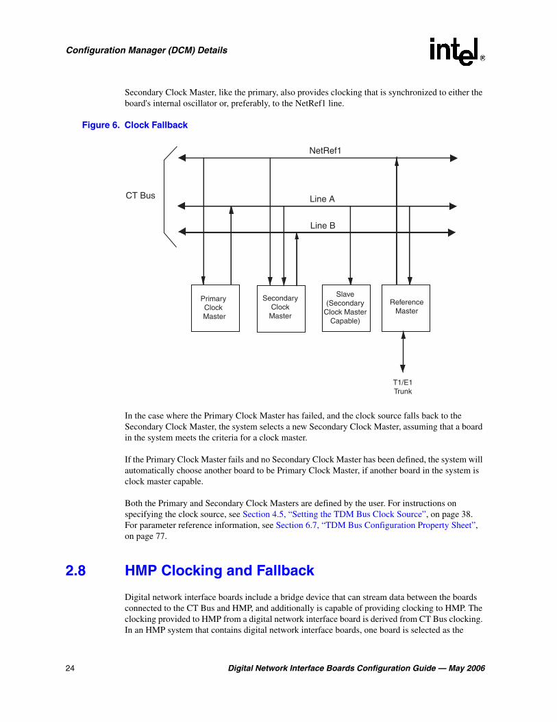
For the following discussion, refer to Figure 6, “Clock Fallback”, on page 24 for an illustration of the CT Bus clocking concepts.
The Primary Clock Master is a device (board) that provides timing to all other devices attached to the bus. The Primary Clock Master drives bit and framing clocks for all of the other boards (slaves) in the system via CT Bus Line A or Line B.This bus clocking is synchronized to either the board's internal oscillator or, preferably, to the NetRef1 line which provides a timing reference (8 kHz) derived from a T1 or E1 interface signal.
The timing reference is provided by the Reference Master board. A T1 or E1 trunk on the Reference Master board is the source for the T1 or E1 interface signal from which the 8 kHz timing reference is derived. The timing reference is sent from the Reference Master board to the NetRef1 line.
In addition, a Secondary Clock Master can be defined as a backup for the same purpose. This board, like the Primary Clock Master, is capable of driving the bit and framing clocks for all of the other boards in the system. The Secondary Clock Master uses whichever CT Bus line (A or B) is not defined for the Primary Master Clock. If the system senses a failure of the Primary Clock Master, the system will cause the clock source to fall back to the Secondary Clock Master. The
24 Digital Network Interface Boards Configuration Guide — May 2006
Configuration Manager (DCM) Details
Secondary Clock Master, like the primary, also provides clocking that is synchronized to either the board's internal oscillator or, preferably, to the NetRef1 line.
Figure 6. Clock Fallback
In the case where the Primary Clock Master has failed, and the clock source falls back to the Secondary Clock Master, the system selects a new Secondary Clock Master, assuming that a board in the system meets the criteria for a clock master.
If the Primary Clock Master fails and no Secondary Clock Master has been defined, the system will automatically choose another board to be Primary Clock Master, if another board in the system is clock master capable.
Both the Primary and Secondary Clock Masters are defined by the user. For instructions on specifying the clock source, see Section 4.5, “Setting the TDM Bus Clock Source”, on page 38. For parameter reference information, see Section 6.7, “TDM Bus Configuration Property Sheet”, on page 77.
2.8 HMP Clocking and Fallback
Digital network interface boards include a bridge device that can stream data between the boards connected to the CT Bus and HMP, and additionally is capable of providing clocking to HMP. The clocking provided to HMP from a digital network interface board is derived from CT Bus clocking. In an HMP system that contains digital network interface boards, one board is selected as the
Line A
Line B
NetRef1
CT Bus
PrimaryClock
Master
SecondaryClock
Master
Slave(Secondary
Clock MasterCapable)
ReferenceMaster
T1/E1Trunk

Digital Network Interface Boards Configuration Guide — May 2006 25
Configuration Manager (DCM) Details
Primary Clock Master for HMP. Additional digital network interface boards serve as backup clocking sources for HMP, via a fallback list, should the HMP Primary Clock Master fail.
In an HMP system with no digital network interface boards or no active boards, HMP clocking is derived from an alternate system clock source. This alternate system clock source also serves as the last HMP clock source on the fallback list.
The parameters for configuring clocking provided to HMP from digital network interface boards are located on the Bridge Device Configuration Property sheet in the configuration manager utility. For instructions on configuring these parameters, see Section 4.6, “Modifying Bridge Device Parameters”, on page 39. For parameter reference information, see Section 6.2, “Bridge Device Configuration Property Sheet”, on page 62.

26 Digital Network Interface Boards Configuration Guide — May 2006
Configuration Manager (DCM) Details

Digital Network Interface Boards Configuration Guide — May 2006 27
33.CONFIG File Details
This chapter provides background information about CONFIG (.config) files including directory location and formatting conventions. This chapter also includes information to help you set the parameters contained in the CONFIG file including the following:
• CONFIG File Formatting Conventions . . . . . . . . . . . . . . . . . . . . . . . . . . . . . . . . . . . . . 27
• CONFIG File Sections. . . . . . . . . . . . . . . . . . . . . . . . . . . . . . . . . . . . . . . . . . . . . . . . . . 28
• [NFAS] Section . . . . . . . . . . . . . . . . . . . . . . . . . . . . . . . . . . . . . . . . . . . . . . . . . . . . . . . 28
• [CHP] Section . . . . . . . . . . . . . . . . . . . . . . . . . . . . . . . . . . . . . . . . . . . . . . . . . . . . . . . . 29
• [TSC] Section . . . . . . . . . . . . . . . . . . . . . . . . . . . . . . . . . . . . . . . . . . . . . . . . . . . . . . . . 30
3.1 CONFIG File Formatting Conventions
The CONFIG (.config) files, located in the data directory under INTEL_DIALOGIC_DIR (the environment variable for the directory in which the software is installed), are ASCII files that contain component configuration information required by Intel® telecom boards. When manually editing the CONFIG file, use the following formatting conventions:
ParametersMany CONFIG file parameters use the SetParm command to assign values. The format is SetParm followed by an equal sign, followed by the hexadecimal parameter number, followed by a comma, followed by the parameter value:
SetParm=parameter-number, parameter-value
Additional commands used to set parameters include:
• AddNFASInterface (see “GroupID (Group Identifier)”, on page 103)
• Variant (see Section 3.4, “[CHP] Section”, on page 29)
• defineBSet (see Section 3.5, “[TSC] Section”, on page 30).
SectionsConfiguration parameters are grouped into sections. In general, each section begins with a section name enclosed in square brackets. (The section names are listed and described in Section 3.2, “CONFIG File Sections”, on page 28.) The parameters for the section immediately follow the section name.
[section-name]
Some sections group parameters that apply to a specific network interface (trunk) or channel (line). These section names are followed by a period (.) and the trunk number. For sections that group parameters like this, there is a separate section for each trunk.
[section-name.trunk-number]

28 Digital Network Interface Boards Configuration Guide — May 2006
CONFIG File Details
CommentsComments can be added to the CONFIG file. If you use an exclamation point (!) anywhere on a line, all text to the right of the exclamation point until the end of the line is treated as a comment (ignored).
! comment
For a list of all CONFIG file parameters, see Chapter 7, “CONFIG File Parameter Reference”.
3.2 CONFIG File Sections
CONFIG file parameters are grouped in sections based on the board components and subcomponents being configured. Modifiable CONFIG file sections include the following:
Note: CAS and R2MF protocols are configured using Protocol Development Kit (PDK) parameters. For more information, see the Global Call Country Dependent Parameters (CDP) for PDK Protocols Configuration Guide.
[0x2c]Defines parameters used to set the tail length, or tap length, of the enhanced echo canceller.
[lineAdmin.x]Defines line device parameters applicable to each trunk on a board that has T1 or E1 trunks.
[NFAS] and [NFAS.x]Non-Facility Associated Signaling (NFAS). Defines the Primary D channel and NFAS trunk parameters. The [NFAS] section defines the number of NFAS groups on a board. The [NFAS.x] sections define the parameters specific to each group. For details about setting the NFAS parameters, see Section 3.3, “[NFAS] Section”, on page 28.
[CCS] and [CCS.x]Common Channel Signaling (CCS). Defines common channel signaling parameters applicable to technologies such as ISDN. The [CCS] section defines board-based parameters and the [CCS.x] section defines the line-based parameters.
[CHP]Channel Protocol (CHP). Defines the telephony communication protocol that is used on each network interface using the Variant Define n command. For details about setting [CHP] parameters using the Variant Define n command, see Section 3.4, “[CHP] Section”, on page 29.
[TSC]Telephony Service Component (TSC). Defines sets of B channels and associated characteristics using the defineBSet command. For details about setting [TSC] parameters using the defineBSet command, see Section 3.5, “[TSC] Section”, on page 30.
3.3 [NFAS] Section
Non-Facility-Associated Signaling (NFAS) uses a single ISDN PRI D channel to provide signaling and control for up to 10 ISDN PRI lines. Normally, on an ISDN PRI line, one D channel is used for signaling and 23 B channels (bearer channels) are used for transferring information. In an NFAS

Digital Network Interface Boards Configuration Guide — May 2006 29
CONFIG File Details
configuration, therefore, one D channel can support the signaling and control for up to 239 B channels. The trunk that provides the signaling is called the primary D channel. The trunks that use all 24 channels as B channels are called NFAS trunks.
Notes: 1. For a board containing multiple primary D channels, the maximum number of trunks supported by each NFAS group on that board is reduced. This is due to the additional message load on the board’s CPU.
2. NFAS is supported on only the ISDN NI-2, 4ESS, 5ESS, and DMS protocols.
3. NFAS D channel backup (DCBU) is supported only on ISDN NI-2 protocol.
4. When NFAS is used, the SignalingType parameter in the [lineAdmin] section of the CONFIG file must be modified. For details about this parameter modification, see Section 7.2, “[lineAdmin.x] Parameters (Digital Voice)”, on page 93.
The CONFIG file contains an [NFAS] section and multiple [NFAS.x] sections. The [NFAS] section defines the number of NFAS instances created, that is, defines the number of NFAS groups. For each NFAS group, there is an [NFAS.x] section in the CONFIG file. For example, if there are two NFAS groups defined in the [NFAS] section, there will be two [NFAS.x] sections, [NFAS.1] and [NFAS.2].
NFAS parameters are modified by editing the respective lines in the [NFAS] and [NFAS.x] sections of the CONFIG file. For example, to increase the number of NFAS groups per board from one to four, change the value of NFAS_INSTANCE_MAP (parameter = 0x3E02) from a value of 1 (one group per board) to a binary value of 1111 (four NFAS groups per board) represented by 0xF.
Following is an excerpt from the [NFAS] section of a CONFIG file that illustrates that part of the file before and after editing.
Before editing:
[NFAS] SetParm=0x3e02,0x1 !INSTANCE MAP, default = 1 (1 group/board)
After editing:
[NFAS] SetParm=0x3e02,0xf !INSTANCE MAP - 4 NFAS groups/board
3.4 [CHP] Section
The Channel Protocol (CHP) component implements the telephony communication protocol that is used on each network interface. There are different versions of this component for handling different signaling types as well as different protocol types on different B channels. There is one CHP instance created for each B channel in the system.
The [CHP] section of the CONFIG file is a subset of the [TSC] section. Protocol-specific parameters, primarily in the form of variants, are defined in the [CHP] section. The selection of which of these protocol variants to use on which line (span) is determined in the [TSC] section. For more information on protocol variants selection, see Section 3.5, “[TSC] Section”, on page 30.

30 Digital Network Interface Boards Configuration Guide — May 2006
CONFIG File Details
A number of protocol variants are defined in the [CHP] section of the CONFIG file. Variants are defined by the Variant Define n command, where n is the variant identifier. The Variant Define n command defines variant “n” as all of the parameter definitions in the [CHP] section preceding the command.
Note: If a parameter is defined multiple times prior to the Variant Define n command, then only the last definition of the parameter is used for that variant.
Note: [CHP] T1 Protocol variants are configured using Protocol Development Kit (PDK) parameters. For more information, see the Global Call Country Dependent Parameters (CDP) for PDK Protocols Configuration Guide.
Although protocol variants are defined in the [CHP] section, protocol variants are assigned in the [TSC] section of the CONFIG file. Selecting a particular Variant Define n is accomplished by changing the values of the Inbound and Outbound parameters for a particular line. The Inbound and Outbound parameters are the sixth and seventh parameters respectively in the defineBSet command in the [TSC] section of the CONFIG file.
For information about the defineBSet command and setting TSC parameters, see Section 3.5, “[TSC] Section”, on page 30.
For information about each CHP parameter, see the following sections:
• Section 7.6, “[CHP] Parameters”, on page 109
• Section 7.7, “[CHP] ISDN Protocol Variant Definitions”, on page 110
3.5 [TSC] Section
The [TSC] section of the CONFIG file defines a set of B channels and associated characteristics using the defineBSet command. The syntax of the defineBSet command is:
defineBSet = SetId, LineId, StartChan, NumChans, BaseProtocol, Inbound, OutBound, DChanDesc, Admin, Width, BChanId, SlotId, Direction, Count, [BChanId, SlotId, Direction, Count,] 0
To change a [TSC] parameter, you change the value of the applicable defineBSet parameter in the CONFIG file. For example, to change the protocol variant from 2 to 4 for both inbound and outbound call processing on all 30 channels of line 2, you would change the value of the Inbound and Outbound parameters for line 2 (SetId=20) from 2 to 4. For information on defining protocol variants, see Section 3.4, “[CHP] Section”, on page 29.
Following is an excerpt from the [TSC] section of a CONFIG file that illustrates that part of the file before and after editing.
Before editing:
defineBSet=10,1,1,30, 0,1,1,1,20,1, 1,1,3,15, 16,17,3,15,0 defineBSet=20,2,1,30, 0,2,2,1,20,1, 1,1,3,15, 16,17,3,15,0

Digital Network Interface Boards Configuration Guide — May 2006 31
CONFIG File Details
After editing:
defineBSet=10,1,1,30, 0,1,1,1,20,1, 1,1,3,15, 16,17,3,15,0 defineBSet=20,2,1,30, 0,4,4,1,20,1, 1,1,3,15, 16,17,3,15,0
For information about each TSC parameter, see Section 7.9, “[TSC] defineBSet Parameters”, on page 118.

32 Digital Network Interface Boards Configuration Guide — May 2006
CONFIG File Details

Digital Network Interface Boards Configuration Guide — May 2006 33
44.Configuration Procedures
The following information provides detailed procedures for each major step in the configuration process (some steps may not apply to your configuration):
• Assumptions and Prerequisites . . . . . . . . . . . . . . . . . . . . . . . . . . . . . . . . . . . . . . . . . . . 33
• Order of Procedures. . . . . . . . . . . . . . . . . . . . . . . . . . . . . . . . . . . . . . . . . . . . . . . . . . . . 34
• Starting the Configuration Manager (DCM) . . . . . . . . . . . . . . . . . . . . . . . . . . . . . . . . . 34
• Selecting a Configuration File Set . . . . . . . . . . . . . . . . . . . . . . . . . . . . . . . . . . . . . . . . . 36
• Setting the TDM Bus Clock Source . . . . . . . . . . . . . . . . . . . . . . . . . . . . . . . . . . . . . . . 38
• Modifying Bridge Device Parameters . . . . . . . . . . . . . . . . . . . . . . . . . . . . . . . . . . . . . . 39
• Modifying Bridge Controller Parameters . . . . . . . . . . . . . . . . . . . . . . . . . . . . . . . . . . . 41
• Setting the Bus Companding Method . . . . . . . . . . . . . . . . . . . . . . . . . . . . . . . . . . . . . . 42
• Modifying Other DCM Property Sheet Parameters. . . . . . . . . . . . . . . . . . . . . . . . . . . . 43
• Modifying the FCD File Parameters . . . . . . . . . . . . . . . . . . . . . . . . . . . . . . . . . . . . . . . 44
• Configuring the Global Call CDP File . . . . . . . . . . . . . . . . . . . . . . . . . . . . . . . . . . . . . 45
• Initializing the System . . . . . . . . . . . . . . . . . . . . . . . . . . . . . . . . . . . . . . . . . . . . . . . . . . 46
• Reconfiguring the System . . . . . . . . . . . . . . . . . . . . . . . . . . . . . . . . . . . . . . . . . . . . . . . 46
4.1 Assumptions and Prerequisites
The following assumptions and prerequisites exist regarding the configuration procedures:
• All required software, including prerequisites, have been installed according to the procedures in the software installation guide supplied with your release.
• The release was installed in the default directory under INTEL_DIALOGIC_DIR, the environment variable for the directory in which the software is installed. Command instructions, directories paths and environment variable are shown relative to the default installation directory.
• You have administrative privileges on the local computer and on any remote computer you connect to in order to use the configuration manager (DCM). Contact your network administrator to set up administrative privileges as required.
• If applicable, the Global Call protocols have been installed. The Global Call protocols are provided as part of the release. For information about country dependent parameters associated with a protocol, see the Global Call Country Dependent Parameters (CDP) for PDK Protocols Configuration Guide.

34 Digital Network Interface Boards Configuration Guide — May 2006
Configuration Procedures
4.2 Order of Procedures
Procedures that are required when initially configuring any system are noted as such. The additional procedures may be required depending on your system. Except for the required procedures, configuration procedures should be performed in the order presented. FCD file parameter modifications can be made any time prior to initializing the system.
1. Starting the Configuration Manager (DCM) (required)
2. Selecting a Configuration File Set
3. Setting the TDM Bus Clock Source
4. Modifying Bridge Device Parameters
5. Modifying Bridge Controller Parameters
6. Setting the Bus Companding Method
7. Modifying Other DCM Property Sheet Parameters
8. Modifying the FCD File Parameters
9. Configuring the Global Call CDP File
10. Initializing the System (required)
11. Reconfiguring the System
4.3 Starting the Configuration Manager (DCM)
Note: Online Help is available for all parameters accessible through the configuration manager (DCM); to access the help, choose Help > Contents in the DCM main window.
To start the DCM, perform the following steps:
1. From the Windows* Start menu, choose Programs > Intel NetStructure HMP > Configuration Manager-DCM to access the Configuration Manager (DCM). The Computer Name dialog box will appear (Figure 7).
Note: The Computer Name dialog box displays automatically the first time you run the DCM with the local computer name as the default. If the Computer Name dialog box is not already displayed, you can get it by choosing File > Connect or by clicking the Connect icon on the DCM main window.

Digital Network Interface Boards Configuration Guide — May 2006 35
Configuration Procedures
Figure 7. Computer Name Dialog Box
Note: The HMP system uses DCOM objects to run HMP software on remote computers. Remote DCM software internally sets up the DCOM security level programmatically. Do not use the Windows* DCOM configuration utility dcomcnfg.exe to change the security settings. If you do, the HMP system may not work properly. For example, on a Windows machine, if you change the setting to Anonymous, the HMP system does not work properly.
Note: To use remote DCM across firewalls, enable the port used by the DCOM Server, DCMObj.exe, in the firewall configuration. DCMObj.exe is located in the bin directory. To determine the port used by DCMObj.exe, first use the Windows Task Manager to find out the PID of DCMObj.exe. Once you know the PID, you can use a port usage utility to find out the port used by DCMObj.exe. Windows XP users can run netstat -o to find the port.
2. Connect to either the local computer or a remote computer as follows:
– To connect to the local computer, click Connect.
– To connect to a remote computer, select the Remote radio button, enter the remote computer name, and click Connect. For TCP/IP networks, you can enter the IP address instead of the remote computer name.
After you connect to a computer, a window will appear that indicates that boards are being detected followed by the DCM main window. The DCM main window contains a tree structure of the boards installed in your system. Refer to Figure 1, “DCM Main Window”, on page 16). In addition to the DCM main window, a system tray icon is also created. For details about the DCM system tray icon, refer to the DCM Online Help.
Continue with any additional configuration procedures that are applicable to your system.
• If you need to use PCD and FCD files other than the default files, see Section 4.4, “Selecting a Configuration File Set”, on page 36.
• If you need to configure the TDM bus, see Section 4.5, “Setting the TDM Bus Clock Source”, on page 38.
• If you need to configure the bridge device, see Section 4.6, “Modifying Bridge Device Parameters”, on page 39.
• If you need to configure the bridge controller, see Section 4.7, “Modifying Bridge Controller Parameters”, on page 41.
36 Digital Network Interface Boards Configuration Guide — May 2006
Configuration Procedures
• If you are using a T1 or E1 product, see Section 4.8, “Setting the Bus Companding Method”, on page 42.
• If you need to change additional DCM parameters, see Section 4.9, “Modifying Other DCM Property Sheet Parameters”, on page 43.
• If you need to change parameter settings in the FCD file, see Section 4.10, “Modifying the FCD File Parameters”, on page 44.
When you are satisfied with all configuration information, proceed with Section 4.12, “Initializing the System”, on page 46.
4.4 Selecting a Configuration File Set
The first time you configure a board, you can select configuration files other than the default files assigned by the system, in one of these ways: by modifying parameters on the Misc property sheet, by using the Assign Firmware File dialog box, or by modifying parameters on the Trunk Configuration property sheet. For details about configuration file sets, see Section 2.5, “Configuration File Sets”, on page 21.
To select different configuration files using the Misc property sheet, perform the following:
1. Double-click the board model name on the DCM main window to display the board’s property sheets. Refer to Figure 2, “Misc Property Sheet”, on page 17.
Note: You must use this procedure if you want to assign a different PCD/FCD file set to the board.
2. Click the Misc property sheet tab to view all of the Misc property sheet parameters associated with the board.
3. Select the FCDFileName parameter by clicking on it; the selected parameter and its current value are displayed on the bottom of the property sheet.
4. In the Value window of the property sheet, type the name of the FCD file to be assigned to this board.
5. Select the PCDFileName parameter by clicking on it; the selected parameter and its current value are displayed on the bottom of the property sheet.
6. In the Value window of the property sheet, type the name of the PCD file to be assigned to this board.
7. Click the OK button to save all your changes and return to the DCM main window.
To select different configuration files using the Assign Firmware File dialog box, perform the following:
1. From the DCM System pull-down menu, select the Auto Detect Devices option. The Assign Firmware File dialog box will appear. Refer to Figure 8.

Digital Network Interface Boards Configuration Guide — May 2006 37
Configuration Procedures
2. In the Available Firmware window, select the PCD file that corresponds to the configuration file set you want to assign to this board.
3. Click the OK button. The selected PCD file name will be assigned to the PCDFileName parameter located on the board’s Misc property sheet. The corresponding FCD file will be assigned to the FCDFileName parameter also located on the board’s Misc property sheet.
To select different configuration files using the Trunk Configuration property sheet, perform the following:
1. From the DCM Main Window, Figure 1, highlight the board you wish to configure and choose Configure Device from the Device drop down menu. The property sheets for this board will appear.
2. Select the Trunk Configuration property sheet, and assign a protocol type to each trunk on the board. Then click OK to save the configuration. The configuration files will then be generated and set. See Section 6.8, “Trunk Configuration Property Sheet”, on page 86.
Figure 8. Assign Firmware File Dialog Box
Continue with any additional configuration procedures that are applicable to your system.
• If you need to configure the TDM bus, see Section 4.5, “Setting the TDM Bus Clock Source”, on page 38.

38 Digital Network Interface Boards Configuration Guide — May 2006
Configuration Procedures
• If you need to configure the bridge device, see Section 4.6, “Modifying Bridge Device Parameters”, on page 39.
• If you need to configure the bridge controller, see Section 4.7, “Modifying Bridge Controller Parameters”, on page 41.
• If you are using a T1 or E1 product, see Section 4.8, “Setting the Bus Companding Method”, on page 42.
• If you need to change additional DCM parameters, see Section 4.9, “Modifying Other DCM Property Sheet Parameters”, on page 43.
• If you need to change parameter settings in the FCD file, see Section 4.10, “Modifying the FCD File Parameters”, on page 44.
When you are satisfied with all configuration information, proceed with Section 4.12, “Initializing the System”, on page 46.
4.5 Setting the TDM Bus Clock Source
The default clock source is the internal oscillator of the Primary Master board. You should derive clocking from a digital network trunk if available, not from a board’s internal oscillator. The internal oscillator should be used as the clock source only for internal testing purposes.
1. To access the clocking settings in the DCM, double-click Bus-0 under TDM Bus in the DCM tree structure of configured devices. Refer to Figure 1, “DCM Main Window”, on page 16. The TDM Bus Configuration property sheet for Bus-0 is displayed. Refer to Figure 3, “TDM Bus Configuration Property Sheet”, on page 18.
2. Designate a board as the primary master by performing the following:
2a. Select the Primary Master FRU (User Defined) parameter.
2b. In the Value list box select the name of the board that will provide the clocking to the bus.
2c. Click Apply.
3. If the Primary Master board is deriving system clocking from a digital network trunk connected to a Network Reference (NETREF) board (also known as the Reference Master board), perform the following. Otherwise, if you are using the Primary Master board’s internal oscillator as the clocking source, skip to Step 4.
3a. Select the NETREF One FRU (User Defined) parameter.
3b. In the Value box, type the name of the board that contains the network interface which will provide a network reference clock to the system. The board name you enter should be the same name as displayed in the DCM main window.
3c. Click Apply.
3d. Specify the source of the network reference clock (specifically, the trunk on the board containing the digital network interface providing the clock) via the Derive NETREF One From (User Defined) parameter.
3e. Click Apply.

Digital Network Interface Boards Configuration Guide — May 2006 39
Configuration Procedures
4. Configure the Primary Master board to use the correct clock reference by setting the Derive Primary Clock From (User Defined) parameter to either NETREF_1 or Internal Oscillator.
5. Click OK.
6. Designate a board as the secondary clock master by performing the following:
6a. Select the Secondary Master FRU (User Defined) parameter.
6b. In the Value list box, select the name of the board that will provide the clocking to the bus if the primary master fails.
6c. Click Apply.
6d. Configure the Secondary Master board to use the correct clock reference by setting the Derive Secondary Clock From (User Defined) parameter to either NETREF_1 or Internal Oscillator.
6e. Click OK.
Continue with any additional configuration procedures that are applicable to your system.
• If you need to configure the bridge device, see Section 4.6, “Modifying Bridge Device Parameters”, on page 39.
• If you need to configure the bridge controller, see Section 4.7, “Modifying Bridge Controller Parameters”, on page 41.
• If you are using a T1 or E1 product, see Section 4.8, “Setting the Bus Companding Method”, on page 42.
• If you need to change additional DCM parameters, see Section 4.9, “Modifying Other DCM Property Sheet Parameters”, on page 43.
• If you need to change parameter settings in the FCD file, see Section 4.10, “Modifying the FCD File Parameters”, on page 44.
When you are satisfied with all configuration information, proceed with Section 4.12, “Initializing the System”, on page 46.
4.6 Modifying Bridge Device Parameters
Intel NetStructure® Digital Network Interface boards have a bridge device that enables communication and media streaming between HMP and the boards on the CT Bus. The bridge device parameters are used by these digital network interface boards. Some parameters are read only, while others can be configured. Configurable parameters come with default values. For detailed parameter reference information, see Section 6.2, “Bridge Device Configuration Property Sheet”, on page 62.
To change default values of configurable bridge device parameters for a board, follow these instructions:
1. Double-click the board model name in the DCM main window to display the board’s property sheets. The Misc property sheet is displayed; see Figure 2.

40 Digital Network Interface Boards Configuration Guide — May 2006
Configuration Procedures
2. Click on the Bridge Device Configuration property sheet tab to view all of the bridge device parameters associated with the board.
3. If desired, designate this specific bridge device as a primary master by performing the following:
3a. Select the BridgeDeviceHMPClockMasterFallbackNbrUserDefined parameter.
3b. In the Value list box, select a new value that is lower than the default value. For example, select 1 or 2. The bridge device with the lowest number is chosen by the bridge controller as the HMP clock master. Bridge devices with higher numbers serve as fallback clock masters as needed. If multiple boards share the same value, the bridge controller determines the bridge device that will be the HMP clock master. (The default value for all digital network interface boards is 3).
4. If desired, adjust the number of HMP to Board streams for this bridge device.
4a. Select the BridgeDeviceMaxHBStreamSetting parameter.
4b. In the Value list box, select a new value. (The default value is 256.)
Note: You can also adjust the number of HMP to Board streams at a system level using the SystemMaxHBStreams parameter on the Bridge Controller property sheet. See Section 4.7, “Modifying Bridge Controller Parameters”, on page 41.
5. If desired, adjust the number of Board to HMP streams for this bridge device.
5a. Select the BridgeDeviceMaxBHStreamSetting parameter.
5b. In the Value list box, select a new value. (The default value is 256.)
Note: You can also adjust the number of Board to HMP streams at a system level using the SystemMaxBHStreams parameter on the Bridge Controller property sheet. See Section 4.7, “Modifying Bridge Controller Parameters”, on page 41.
Continue with any additional configuration procedures that are applicable to your system.
• If you need to configure the bridge controller, see Section 4.7, “Modifying Bridge Controller Parameters”, on page 41.
• If you are using a T1 or E1 product, see Section 4.8, “Setting the Bus Companding Method”, on page 42.
• If you need to change parameter settings in the FCD file, see Section 4.10, “Modifying the FCD File Parameters”, on page 44.
• If you have the Global Call Protocols installed, see Section 4.11, “Configuring the Global Call CDP File”, on page 45.
When you are satisfied with all configuration information, proceed with Section 4.12, “Initializing the System”, on page 46.

Digital Network Interface Boards Configuration Guide — May 2006 41
Configuration Procedures
4.7 Modifying Bridge Controller Parameters
Intel NetStructure® Digital Network Interface boards have a bridge device that enables communication and media streaming between HMP and the boards on the CT Bus. The media stream connections are managed by the bridge controller. All parameters on the Bridge Controller property sheet can be configured; the parameters come with default values. For detailed parameter reference information, see Section 6.1, “Bridge Controller Property Sheet”, on page 61.
To change a system’s bridge controller parameter values, follow these instructions:
1. Double-click Bridge-0 device under Bridge Devices in the DCM main window to display the Bridge Controller property sheet.
2. If desired, adjust the number of HMP to Boards streams in the system to be allocated in the HMP to Boards direction.
2a. Select the SystemMaxHBStreams parameter.
2b. In the Value list box, select a new value. (The default value is 512.)
Note: You can also adjust the number of HMP to Board streams at a board level using the BridgeDeviceMaxHBStreamSetting parameter on the Bridge Device Configuration property sheet. See Section 4.6, “Modifying Bridge Device Parameters”, on page 39.
3. If desired, adjust the number of Boards to HMP streams in the system to be allocated in the Boards to HMP direction.
3a. Select the SystemMaxBHStreams parameter.
3b. In the Value list box, select a new value. (The default value is 512.)
Note: You can also adjust the number of Board to HMP streams at a board level using the BridgeDeviceMaxBHStreamSetting parameter on the Bridge Device Configuration property sheet. See Section 4.6, “Modifying Bridge Device Parameters”, on page 39.
4. If desired, adjust the number of Host Streaming Interface (HSI) hold buffers.
4a. Select the BridgeControllerNumberOfHSIHOLDBuffers parameter.
4b. In the Value list box, select a new value. (The default value is 3.)
Continue with any additional configuration procedures that are applicable to your system.
• If you are using a T1 or E1 product, see Section 4.8, “Setting the Bus Companding Method”, on page 42.
• If you need to change parameter settings in the FCD file, see Section 4.10, “Modifying the FCD File Parameters”, on page 44.
• If you have the Global Call Protocols installed, see Section 4.11, “Configuring the Global Call CDP File”, on page 45.
When you are satisfied with all configuration information, proceed with Section 4.12, “Initializing the System”, on page 46.

42 Digital Network Interface Boards Configuration Guide — May 2006
Configuration Procedures
4.8 Setting the Bus Companding Method
The bus companding method is defined using the Media Type (User Defined) parameter. This parameter is associated with the TDM Bus Configuration for Bus-0 in DCM. Initially, the Media Type (User Defined) value is set to Default. This causes the system to default to the value determined by the Media Type (Resolved) parameter. In this case, the bus companding method as indicated by Media Type (Resolved) parameter is:
• mu-law: for digital network interface boards
For digital network interface boards whose trunks can individually connect to either T1 or E1 interfaces, the companding method will automatically be converted on the board, if necessary, on a trunk-by-trunk basis to agree with that of the TDM Bus companding method. For example, if the TDM Bus is set to mu-law, the board will perform A-law to mu-law conversion between the board and TDM Bus for the E1 trunks.
• For boards that have a physical network interface, but are configured as resource only (i. e. no protocol loaded), the firmware will still determine the network interfaces and force the resolution of the Media Type to be either A-law for E1 physical interfaces or mu-law for T1 physical interfaces.
• If boards that can only be resolved as mu-law and boards that can only be resolved as A-law are installed in the same system, the system will not complete the initialization process and will log an error.
If desired, follow these instructions to set the bus companding method:
1. Double-click Bus-0 under TDM Bus in the DCM main window to display the TDM Bus Configuration property sheet for Bus-0.
2. Select the Media Type (User Defined) parameter by clicking on it.
3. Select A-Law or mu-Law, as appropriate, from the pull-down menu.
4. Click OK to set the parameter and return to the DCM main window.
Continue with any additional configuration procedures that are applicable to your system.
• If you need to change additional DCM parameters, see Section 4.9, “Modifying Other DCM Property Sheet Parameters”, on page 43.
• If you need to change parameter settings in the FCD file, see Section 4.10, “Modifying the FCD File Parameters”, on page 44.
When you are satisfied with all configuration information, proceed with Section 4.12, “Initializing the System”, on page 46.

Digital Network Interface Boards Configuration Guide — May 2006 43
Configuration Procedures
4.9 Modifying Other DCM Property Sheet Parameters
Within the DCM, each board has a set of property sheets that display the board’s configuration parameters, grouped together on tabs according to the type of board functionality that they affect. To change a board’s configuration parameters, follow this procedure:
1. Double-click the board model name in the DCM main window to display the board’s property sheets. The Misc Property Sheet is displayed; see Figure 2, “Misc Property Sheet”, on page 17.
2. Click a property sheet tab to view all of the board parameters associated with a particular property sheet. For example, to view the parameters associated with the Physical property sheet, click the Physical tab. Refer to Figure 9.
Refer to the DCM Online Help for a description of property sheets and parameters. The DCM Online Help can be accessed from the Help pull-down menu located on the DCM main window or by pressing the F1 key. To access information about a specific parameter, highlight the parameter in the DCM and press the F1 key.
3. Select a parameter by clicking it; the selected parameter and its current value are displayed on the bottom of the property sheet.
4. In the Value box of the property sheet, type the parameter value or select a value from the drop-down list.
5. Click Apply to save the change.
6. Repeat this procedure for all parameters that need to be modified.
7. Click OK to save all your changes and return to the DCM main window.
Continue with any additional configuration procedures that are applicable to your system.
• If you need to change additional FCD file parameters, see Section 4.10, “Modifying the FCD File Parameters”, on page 44.
When you are satisfied with all configuration information, proceed with Section 4.12, “Initializing the System”, on page 46.

44 Digital Network Interface Boards Configuration Guide — May 2006
Configuration Procedures
Figure 9. Physical Property Sheet
4.10 Modifying the FCD File Parameters
If the default settings in the FCD files are not appropriate for your configuration, you can modify the FCD file parameters using the CONFIG file and the fcdgen utility. Modifications can be made at any time prior to starting the system. For each FCD file to be modified, the procedure includes:
1. Editing the CONFIG File
2. Generating the FCD File
4.10.1 Editing the CONFIG File
The first step in generating a modified FCD file is to edit the corresponding CONFIG file. Once the CONFIG file parameters are modified, the fcdgen utility is used to convert the CONFIG file to an FCD file.
Note: If you want to preserve the default parameter values contained in the CONFIG file, make a backup copy of the file prior to editing it.

Digital Network Interface Boards Configuration Guide — May 2006 45
Configuration Procedures
To edit the CONFIG file:
1. From the command prompt, go to the data directory and locate the CONFIG file.
2. Using a text editor (for example, WordPad), open the CONFIG file that corresponds to the FCD file you want to modify. By default, the CONFIG file will have the same file name as the FCD file, but with a .config extension.
3. Edit the CONFIG file as necessary.
For a detailed description of the CONFIG file sections and formatting conventions, see Chapter 3, “CONFIG File Details”. For details about CONFIG file parameters, see Chapter 7, “CONFIG File Parameter Reference”.
4. Save and close the CONFIG file.
Proceed with Section 4.10.2, “Generating the FCD File”, on page 45.
4.10.2 Generating the FCD File
In order to generate an FCD file, the corresponding CONFIG file must be converted to an FCD file. fcdgen converts the CONFIG file into a format that can be read directly by the downloader.
1. From the command prompt, go to the data directory.
2. Execute fcdgen as follows:
..\bin\fcdgen -f <input file>.config -o <output file>.fcd
For example:
..\bin\fcdgen -f ghmp1_hmpdsb_2_qsige1.config
The resulting FCD file is created in the data directory. If the -o option is omitted from the command, the default output FCD file will have the same filename as the user-modified input configuration file, but with a .fcd extension.
If you are using Global Call CDP files, proceed with Section 4.11, “Configuring the Global Call CDP File”, on page 45.
When you are satisfied with all configuration information, proceed with Section 4.12, “Initializing the System”, on page 46.
4.11 Configuring the Global Call CDP File
If you are using the Global Call protocols, see the Global Call Country Dependent Parameters (CDP) for PDK Protocols Configuration Guide for the following configuration procedures:
• Configuring the country dependent parameters (CDP) file
• Downloading the protocol and CDP file
46 Digital Network Interface Boards Configuration Guide — May 2006
Configuration Procedures
4.12 Initializing the System
Note: The new configuration settings will not take effect until the system is initialized. Before system initialization, make sure you perform all of the necessary configuration procedures.
To initialize the system for the first time, proceed as follows:
1. From the DCM main window, select the root of the tree structure (Configured Devices on...).
2. Choose Device > Enable Device(s) or click the Enable Device(s) icon on the DCM toolbar.
3. Choose System > Start System or click the Start all Enabled Devices icon on the DCM toolbar.
4. Verify the system has started (indicated by a status of “Started” in the System status line at the bottom of the DCM main window).
5. After starting the system for the first time, you may want to use some of the tools, such as demo programs, provided by the system software to verify that your system is operating properly.
6. If you have problems, see the Troubleshooting section of the Administration Guide. Problems on initial startup are typically caused by errors in your configuration settings.
Once the system is initialized for the first time, the system can be reconfigured and re-initialized as described in Section 4.13, “Reconfiguring the System”, on page 46.
4.13 Reconfiguring the System
Once the HMP system is initialized for the first time, if you need to modify and re-download the parameters, following these instructions to reconfigure the system:
1. Before you stop the system, stop the application ensuring all channels have been closed.
2. Launch the configuration manager utility by choosing Programs > Intel NetStructure HMP > Configuration Manager-DCM from the Windows Start menu. The DCM main window is displayed. Refer to Figure 1, “DCM Main Window”, on page 16.
3. Stop either the complete system or a single board, as appropriate:
• To stop the system, choose System > Stop System or click the Stop System icon in the DCM main window before changing parameter values. The system is stopped once “Stopped” is displayed on the System status line at the bottom of the DCM main window.
• To stop a single board, choose Device > Stop Device.
4. Double-click the board model name to display the configuration data property sheets pertaining to the board. Refer to Figure 1, “DCM Main Window”, on page 16.

Digital Network Interface Boards Configuration Guide — May 2006 47
Configuration Procedures
5. If you wish to restore the board’s DCM parameter settings to their default values, choose Device > Restore Defaults in the DCM main window. This resets all of the board’s modified parameters to their default values in the DCM.
6. If you wish to reset the FCD file parameters to their default values, perform the following:
Note: This step only applies if a backup copy of the CONFIG file was made prior to modifying the parameters.
6a. Rename the backup CONFIG file to its original file name.
6b. Generate a new FCD file as described in Section 4.10, “Modifying the FCD File Parameters”, on page 44.
7. Modify parameters as described in any of the following procedures that apply:
• Section 4.4, “Selecting a Configuration File Set”, on page 36
• Section 4.5, “Setting the TDM Bus Clock Source”, on page 38
• Section 4.6, “Modifying Bridge Device Parameters”, on page 39
• Section 4.7, “Modifying Bridge Controller Parameters”, on page 41
• Section 4.8, “Setting the Bus Companding Method”, on page 42
• Section 4.9, “Modifying Other DCM Property Sheet Parameters”, on page 43
• Section 4.10, “Modifying the FCD File Parameters”, on page 44
8. When you’re finished changing parameters, restart the system or a single board, as appropriate:
• Start the whole system by choosing System > Start System or clicking the Start System icon in the DCM main window. The system is started once “Started” is displayed on the System status line at the bottom of the DCM main window. The firmware and new configuration settings are downloaded once the system is started.
• To start a single board, choose Device > Start Device. The firmware and new configuration settings are downloaded to the board once the board is started.
For detailed procedures about reconfiguration and other administrative tasks, see the system release administration guide supplied with your software.

48 Digital Network Interface Boards Configuration Guide — May 2006
Configuration Procedures

Digital Network Interface Boards Configuration Guide — May 2006 49
55.Echo Cancellation
This chapter discusses echo cancellation support and configuration in the Intel NetStructure® Host Media Processing software. The following topics are covered:
• Echo Cancellation Background Information . . . . . . . . . . . . . . . . . . . . . . . . . . . . . . . . . 49
• Echo Cancellation Features . . . . . . . . . . . . . . . . . . . . . . . . . . . . . . . . . . . . . . . . . . . . . . 51
• Using Echo Cancellation . . . . . . . . . . . . . . . . . . . . . . . . . . . . . . . . . . . . . . . . . . . . . . . . 52
• Configuring Echo Cancellation . . . . . . . . . . . . . . . . . . . . . . . . . . . . . . . . . . . . . . . . . . . 53
• Echo Cancellation Sample Scenarios . . . . . . . . . . . . . . . . . . . . . . . . . . . . . . . . . . . . . . 56
5.1 Echo Cancellation Background Information
This section provides background information on echo cancellation:
• Overview
• Acoustic Echo
• Electrical Echo
5.1.1 Overview
The presence of echo on a media stream can negatively impact user satisfaction with voice quality. The degree to which echo is objectionable depends on both the loudness of the echo and the total round-trip delay. The impact of an echo increases as round-trip delays increase, affecting the user’s perception of echo. If the delay is small (less than 20 ms), the user hears nothing or at most a reverberant sounding side-tone. Larger delays, however, lead to a subjective annoyance perceived as echo. The larger the delay, the less masking there is by the direct speech and the more annoying the echo becomes.
The presence of echo on a media stream can also negatively impact the reliability of automated media processing such as voice recognition or digit detection when voice prompts, for example, are played to a caller. In this case, a round-trip echo delay of less than 20 ms makes the returned echo unacceptable. For media processing algorithms, it is the loudness of the echo that is most problematic. Media processing algorithms typically function much better when echo is removed, or at a minimum suppressed to very low levels.
There are two basic types of echo to consider: acoustic echo and electrical echo.
5.1.2 Acoustic Echo
Acoustic echo occurs when sound waves emitted from the receiver of an analog or digital handset (telephone) are reflected back, or coupled back, into the microphone of that handset. If the echo is
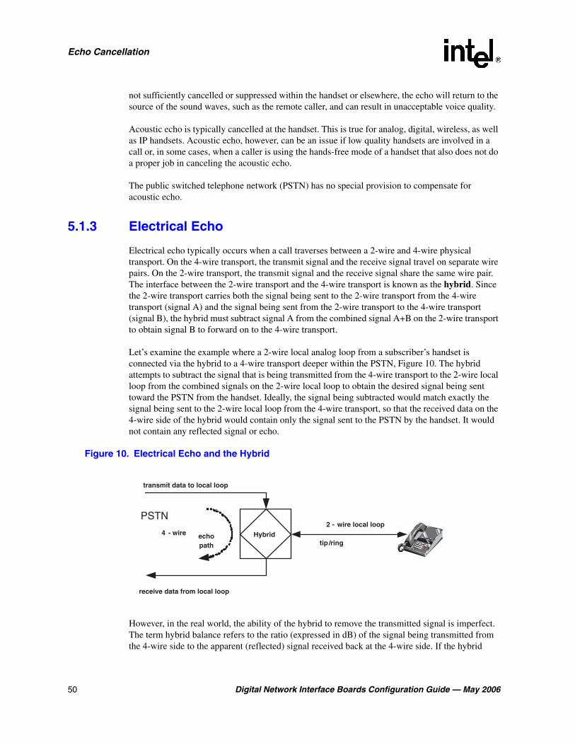
50 Digital Network Interface Boards Configuration Guide — May 2006
Echo Cancellation
not sufficiently cancelled or suppressed within the handset or elsewhere, the echo will return to the source of the sound waves, such as the remote caller, and can result in unacceptable voice quality.
Acoustic echo is typically cancelled at the handset. This is true for analog, digital, wireless, as well as IP handsets. Acoustic echo, however, can be an issue if low quality handsets are involved in a call or, in some cases, when a caller is using the hands-free mode of a handset that also does not do a proper job in canceling the acoustic echo.
The public switched telephone network (PSTN) has no special provision to compensate for acoustic echo.
5.1.3 Electrical Echo
Electrical echo typically occurs when a call traverses between a 2-wire and 4-wire physical transport. On the 4-wire transport, the transmit signal and the receive signal travel on separate wire pairs. On the 2-wire transport, the transmit signal and the receive signal share the same wire pair. The interface between the 2-wire transport and the 4-wire transport is known as the hybrid. Since the 2-wire transport carries both the signal being sent to the 2-wire transport from the 4-wire transport (signal A) and the signal being sent from the 2-wire transport to the 4-wire transport (signal B), the hybrid must subtract signal A from the combined signal A+B on the 2-wire transport to obtain signal B to forward on to the 4-wire transport.
Let’s examine the example where a 2-wire local analog loop from a subscriber’s handset is connected via the hybrid to a 4-wire transport deeper within the PSTN, Figure 10. The hybrid attempts to subtract the signal that is being transmitted from the 4-wire transport to the 2-wire local loop from the combined signals on the 2-wire local loop to obtain the desired signal being sent toward the PSTN from the handset. Ideally, the signal being subtracted would match exactly the signal being sent to the 2-wire local loop from the 4-wire transport, so that the received data on the 4-wire side of the hybrid would contain only the signal sent to the PSTN by the handset. It would not contain any reflected signal or echo.
Figure 10. Electrical Echo and the Hybrid
However, in the real world, the ability of the hybrid to remove the transmitted signal is imperfect. The term hybrid balance refers to the ratio (expressed in dB) of the signal being transmitted from the 4-wire side to the apparent (reflected) signal received back at the 4-wire side. If the hybrid
Hybridechopath
transmit data to local loop
2 - wire local loop
tip /ring4 - wire
receive data from local loop
PSTN

Digital Network Interface Boards Configuration Guide — May 2006 51
Echo Cancellation
balance is not perfect due to impedance mismatches, for instance, then a fraction of the signal being sent is reflected back to the sender. If a delay in the network occurs, the sender hears an echo, which can be objectionable.
The PSTN compensates for electrical echo created within the PSTN under certain connections by inserting echo suppressors or cancellation devices in the path of the call. This is done when a hybrid is included within the route of the call and when the round-trip echo delay exceeds a limit, typically less than 25 ms, above which the echo is deemed to be objectionable. This would be the case, for example, for some long distance calls as well as calls using a satellite link. For the majority of calls, including local calls and also many long distance calls, the round-trip delays are well below 25 ms and, therefore, echo compensation is not provided by the PSTN.
The criteria used to determine when or when not to insert echo compensation in the PSTN, however, assumes that terminal devices such as handsets and combinations of PBX’s with handsets behind them add relatively small additional delays beyond the delays resulting from the PSTN connection. When echo exists on the received media stream and additional delays are introduced into the call connection beyond those budgeted by the PSTN, echo cancellation is required if these additional delays cause the total round-trip delay to exceed approximately 25 ms. If echo cancellation is not provided under these circumstances, callers may experience objectionable echo.
An example of when echo cancellation is not provided is for call connections that span PSTN and IP networks. While the round-trip delay may be small (a few milliseconds on the PSTN side) the delays introduced by the IP network portion of the connection may be in the order of 100 ms. IP networks can also introduce lost or replaced packets, as well as packet jitter, making for a non-linear environment in which it is very difficult to identify and cancel all echoes at the point where media leaves the packet network. Due to these significant delays and potential impairments, gateways which interface between the PSTN and IP network are required to remove any echo received from the PSTN side prior to transmitting audio onto the IP network. Likewise, IP phones must also remove echo before transmitting audio onto the IP network. Conferencing is another example where additional delays are added into the connection path. Therefore, conference bridges typically provide echo cancellation, removing the echo received from each conference party prior to summing the received audio.
5.2 Echo Cancellation Features
Echo cancellation support is available for circuit-switched connections that may contain echo on the received media stream. This feature is applicable to Intel NetStructure® Digital Network Interface boards which provide public switched telephone network (PSTN) connectivity for HMP.
Echo cancellation support is in compliance with ITU-T G.168 recommendation and can be controlled using runtime API functions or CONFIG file parameters. It is recommended that you control echo cancellation on a channel by channel basis using runtime API functions when they are available. The boards support tail lengths of up to 64 ms.
Echo cancellation capability is provided on the following devices in Intel NetStructure® Host Media Processing software:
• IP media device
• signal detector of the voice device
52 Digital Network Interface Boards Configuration Guide — May 2006
Echo Cancellation
• conferencing device
• CSP/voice device
5.3 Using Echo Cancellation
Enabling the echo cancellation feature in HMP devices (IP media, voice, conferencing, and continuous speech processing) is typically required when HMP devices receive media streams from the public switched telephone network (PSTN) via the DTI devices on the T1/E1 single span (DNI300TEPHMP) or the T1/E1 quad span (DNI1200TEPHMP) boards.
Note: DTI devices refer to digital network interface devices, which is used interchangeably with digital trunk interface devices.
While T1/E1 interfaces are digital interfaces, analog links may be part of the end-to-end connections. When this is the case, electrical echo may be present unless the PSTN provides echo cancellation on the connection, which it does not normally do. The HMP echo cancellation feature only addresses electrical echo. It does not address acoustic echo which is typically handled by the handsets (telephones) where acoustic echo could potentially be introduced into the network. See Section 5.1, “Echo Cancellation Background Information”, on page 49 for an overview of echo cancellation and the types of echo.
Enabling the echo cancellation feature in HMP devices is not required for the following:
• Media streams received from PSTN connections via the T1/E1 dual span (DNI601TEPHMP) board since this board provides on-board echo cancellation as part of the DTI resources.
For information about echo cancellation settings on the T1/E1 dual span board, see Section 7.1, “[0x2c] Echo Cancellation Parameters”, on page 92.
• Media streams received from the DSI162HMP digital station interface boards, which provide interfaces to digital stations (handsets). In this case there is no electrical echo since the end-to-end connection is purely digital. Also, it is assumed that the digital handsets adequately cancel acoustic echo.
• Media streams received from the IP packet network via IP media devices. Due to the delays associated with the packet network, echo must be removed prior to transmitting voice (audio) onto the packet network. This is the responsibility of IP endpoints such as gateways and IP phones. Therefore, it is assumed that the media streams received from the IP packet network are free of any objectionable echo.
Since the echo cancellation feature provided by HMP devices consumes CPU resources, echo cancellation should only be applied when needed. For this reason, runtime application control is available to both enable and disable echo cancellation on a per connection or per channel basis. See Section 5.4, “Configuring Echo Cancellation”, on page 53 for more information.

Digital Network Interface Boards Configuration Guide — May 2006 53
Echo Cancellation
5.4 Configuring Echo Cancellation
Echo cancellation can be configured on one or more HMP devices as needed. The following topics provide more information about configuring echo cancellation:
• Echo Cancellation on IP Media Devices
• Echo Cancellation on Voice Devices
• Echo Cancellation on Conferencing Devices
• Echo Cancellation on CSP/Voice Devices
Note: The information in the following subsections does not apply to the T1/E1 dual span (DNI601TEPHMP) board, because this board provides on-board echo cancellation as part of the DTI resources.
5.4.1 Echo Cancellation on IP Media Devices
The IP media device supports echo cancellation on tail lengths up to 64 ms. The default echo cancellation settings on IP media devices are as follows: echo cancellation is disabled, non-linear processing (NLP) is enabled, and the tail length is 16 ms.
Echo cancellation features of the IP media device can be managed using the IP Media Library API or the Global Call API library.
IP Media Library API
Echo cancellation features of the IP media device can be controlled and monitored using IP Media Library API functions.
Echo cancellation can be turned on or off on a per channel (device) basis using ipmSetParm( ) in conjunction with PARMCH_ECACTIVE in the IPM_PARM_INFO structure.
The echo cancellation tail length can be set using ipmSetParm( ) in conjunction with PARMCH_ECHOTAIL in the IPM_PARM_INFO structure.
The echo cancellation NLP feature can be turned on or off using ipmSetParm( ) in conjunction with PARMCH_ECNLP_ACTIVE in the IPM_PARM_INFO structure.
Echo cancellation settings can be monitored using ipm_GetParm( ) in conjunction with the following in the IPM_PARM_INFO structure: PARMCH_ECACTIVE, PARMCH_ECHOTAIL, and PARMCH_ECNLP_ACTIVE.
The following usage rules apply:
• NLP can only be disabled after echo cancellation has been enabled and the ipm_StartMedia( ) function has been invoked.
• Disabling echo cancellation, invoking the ipm_Stop( ) function, or invoking the ipm_ModifyMedia( ) function will cause NLP to be reset to the enabled state. Therefore, if NLP needs to be disabled, you must invoke ipm_SetParm( ) to disable NLP each time the

54 Digital Network Interface Boards Configuration Guide — May 2006
Echo Cancellation
ipm_StartMedia( ) or ipm_ModifyMedia( ) is invoked. This assumes that echo cancellation was previously enabled.
• If echo cancellation was also disabled, echo cancellation must be re-enabled either before or after invoking ipm_StartMedia( ) or ipm_ModifyMedia( ). In either case, echo cancellation must also be enabled before ipm_SetParm( ) is invoked to disable NLP.
For more information, see the IP Media API Library documentation.
Global Call API Library
Alternatively, echo cancellation features of the IP media device can be controlled using the Global Call API Library.
Echo cancellation settings can be modified using the gc_SetUserInfo( ) function to set IP Media Library parameters via the GC_PARM_BLK structure. You can set any IP media parameter in the GC_PARM_BLK structure by using gc_util_insert_parm_ref( ) with a set id of IPSET_CONFIG and parameter IDs of IPPARM_IPMPARM with a value as a pointer to the IPM_PARM_INFO structure.
The echo cancellation parameters that may be modified include PARMCH_ECACTIVE, PARMCH_ECHOTAIL, and PARMCH_ECNLP_ACTIVE.
The following usage rule applies:
• NLP can only be disabled after echo cancellation has been enabled and an active call has been established. Upon termination of a call, NLP will be reset to the enabled state. Therefore, if NLP needs to be disabled, the gc_SetUserInfo() function will need to be invoked to disable NLP each time a new call is established with echo cancellation enabled.
For more information, refer to the Global Call API Library documentation.
5.4.2 Echo Cancellation on Voice Devices
The signal detector of the voice resource supports echo cancellation on tail lengths up to 8 ms. By default, echo cancellation is disabled. The echo cancellation tail length cannot be modified.
Voice API Library
Echo cancellation features of the voice device can be controlled and monitored using the voice API library.
Echo cancellation can be turned on or off on a per channel (device) basis using dx_setparm( ) in conjunction with DXCH_EC_ACTIVE.
Echo cancellation settings can be monitored using dx_getparm( ) in conjunction with DXCH_EC_ACTIVE.
For more information, refer to the voice API library documentation.

Digital Network Interface Boards Configuration Guide — May 2006 55
Echo Cancellation
5.4.3 Echo Cancellation on Conferencing Devices
The conferencing device supports echo cancellation on a per party basis for tail lengths up to 64 ms. By default, echo cancellation is disabled, and the default tail length is set to 16 ms.
Echo cancellation features of the conferencing device can be managed using the conferencing (DCB) API library and the HMP CONFIG file.
Conferencing API Library
Echo cancellation features of the conferencing device can be controlled using conferencing (DCB) API library functions.
Echo cancellation is disabled by default but can be enabled on a per party basis when establishing a conference using the dcb_estconf( ) function or, when adding a party to a conference using the dcb_addtoconf( ) function.
The dcb_estconf( ) function uses an array of MS_CDT data structures which define the attributes of the conference parties. The dcb_addtoconf( ) function uses a single MS_CDT structure to define the attributes of the party that is being added to the conference.
The chan_attr field in the MS_CDT structure is a bitmask that specifies the party’s properties within the conference. The bit that enables echo cancellation is MSPA_ECHOXCLEN.
The conferencing device echo cancellation tail length and NLP capability cannot be controlled via the conferencing API, but can be controlled via the HMP CONFIG (.config) file. For more information, see HMP CONFIG File.
For more information on conferencing functions and data structures, refer to the Conferencing (DCB) API Library documentation.
HMP CONFIG File
You can modify the conferencing device echo cancellation tail length by editing the HMP CONFIG (.config) file. The tail length setting, however, applies globally to all HMP conferencing channels (devices). The setting also modifies the default value for continuous speech processing (CSP) devices, but the CSP values can be changed on a per channel basis using CSP APIs.
The following line in the CONFIG file allows the echo cancellation tail length to be modified:
[0x2c]
SetParm=0x2c03,128 ! Set EC tail length to 64(8ms), 80(10ms), 128(16ms),192(24ms), 256(32ms), 512(64ms). Default: 128(16ms)
You can enable or disable the conferencing device echo cancellation non-linear processing (NLP) feature by editing the HMP CONFIG file. The NLP setting, however, applies globally to all HMP conferencing channels (devices). The setting also modifies the default value for CSP, but the CSP values can be changed on a per channel basis using CSP APIs.

56 Digital Network Interface Boards Configuration Guide — May 2006
Echo Cancellation
The following line in the CONFIG file allows the echo cancellation NLP feature to be enabled or disabled:
[0x2c]
SetParm=0x2c01, 0x1 ! Enable Echo Canceller NLP (0x1 (enable-default), 0x0 (disable))
After editing the CONFIG file, you must generate a new FCD file for the changes to take effect. See Section 4.10, “Modifying the FCD File Parameters”, on page 44 for information about modifying FCD file parameters.
5.4.4 Echo Cancellation on CSP/Voice Devices
The CSP/voice device supports echo cancellation on tail lengths up to 64 ms. By default, echo cancellation is disabled, and the default tail length is 16 ms.
Note: Modifying echo cancellation related conferencing parameters in the HMP CONFIG file will change corresponding default CSP echo cancellation parameter values.
Continuous Speech Processing API Library
Echo cancellation features of the CSP/voice device can be controlled and monitored using CSP API library functions.
Echo cancellation can be turned on or off on a per channel (device) basis using ec_setparm( ) in conjunction with ECCH_ECHOCANCELLER.
The echo cancellation tail length can be set on a per channel (device) basis using ec_setparm( ) in conjunction with DXCH_EC_TAP_LENGTH.
The echo cancellation non-linear processing (NLP) feature can be turned on or off on a per channel (device) basis using ec_setparm( ) in conjunction with ECCH_NLP.
Echo cancellation settings can be monitored using ec_getparm( ) in conjunction with the following parameters: ECCH_ECHOCANCELLER, DXCH_EC_TAP_LENGTH, and ECCH_NLP.
For more information, refer to the Continuous Speech Processing API Library documentation.
5.5 Echo Cancellation Sample Scenarios
The following examples illustrate the digital network interface (DTI) devices connected to various HMP resources as well as IP only connections.
• DTI and IP Gateway Example
• DTI and IP Conferencing Example
• DTI and CSP/Voice Example

Digital Network Interface Boards Configuration Guide — May 2006 57
Echo Cancellation
• DTI and Voice Example
• IP and IP Connection Example
• IP and CSP/Voice Example
• IP and Voice Example
Note: These examples do not apply to the DTI devices on the T1/E1 dual span (DNI601TEPHMP) board, because this board provides on-board echo cancellation as part of the DTI resources.
5.5.1 DTI and IP Gateway Example
Figure 11 shows an example of a T1/E1 and IP Gateway connection formed by connecting the DTI device to an IP media device, also called an IPM device. In this example, the echo cancellation feature (EC) of the IP media device is enabled, to handle echo on the media stream received from the PSTN via the DTI device.
Figure 11. T1/E1 Gateway Example
5.5.2 DTI and IP Conferencing Example
Figure 12 shows a four-party conferencing example where two DTI devices are connected to the conference as parties A and B, and two IP media devices are connected to the conference as parties C and D.
The echo cancellation feature (EC) of the conference device is enabled for parties A and B, to handle echo on the media stream received from the PSTN via the DTI devices. The EC feature is disabled for parties C and D, and also for both IP media devices.
DTI Device IPM Device
EC

58 Digital Network Interface Boards Configuration Guide — May 2006
Echo Cancellation
Figure 12. DTI and IP Conferencing Example
5.5.3 DTI and CSP/Voice Example
Figure 13 shows an example where the DTI device is connected to a CSP/voice device. The echo cancellation feature (EC) of the CSP/voice device is enabled, to handle echo on the media stream from the PSTN received via the DTI device.
Figure 13. DTI and CSP/Voice Example
5.5.4 DTI and Voice Example
Figure 14 shows an example where the DTI device is connected to a voice device. The echo cancellation feature (EC) of the voice device is enabled, to handle echo on the media stream from the PSTN received via the DTI device.
Figure 14. DTI and Voice Example
DTI DeviceIPM Device
Conf Device
Party C
EC
Party A
EC
Party D
EC
Party B
EC
EC
DTI Device IPM Device
EC
DTI DeviceCSP /Voice
Device
EC
DTI DeviceVoice Device
EC

Digital Network Interface Boards Configuration Guide — May 2006 59
Echo Cancellation
5.5.5 IP and IP Connection Example
Figure 15 shows an IP to IP connection example. The echo cancellation feature (EC) is disabled for both IP media devices. As discussed in Section 5.1.3, “Electrical Echo”, on page 50, echo must be removed from the media stream prior to its transmission on the IP packet network.
Figure 15. IP and IP Connection Example
5.5.6 IP and CSP/Voice Example
Figure 16 shows an example where the IP media device is connected to a CSP/voice device. The echo cancellation feature (EC) of both the CSP/voice device and the IP media device is disabled. As discussed in Section 5.1.3, “Electrical Echo”, on page 50, echo must be removed from the media stream prior to its transmission on the IP packet network.
Figure 16. IP and CSP/Voice Example
5.5.7 IP and Voice Example
Figure 17 shows an example where the IP media device is connected to a voice device. The echo cancellation feature (EC) of both the voice device and the IP media device is disabled. As discussed in Section 5.1.3, “Electrical Echo”, on page 50, echo must be removed from the media stream prior to its transmission on the IP packet network.
Figure 17. IP and Voice Example
IPM Device
EC
IPM Device
EC
IPM DeviceCSP /Voice
Device
ECEC
IPM DeviceVoice Device
ECEC

60 Digital Network Interface Boards Configuration Guide — May 2006
Echo Cancellation

Digital Network Interface Boards Configuration Guide — May 2006 61
66.DCM Parameter Reference
This section lists and describes all parameters contained in the configuration manager (DCM). Parameters are grouped by the property sheet on which they reside. Property sheets are described in alphabetical order and include the following:
• Bridge Controller Property Sheet . . . . . . . . . . . . . . . . . . . . . . . . . . . . . . . . . . . . . . . . . 61
• Bridge Device Configuration Property Sheet . . . . . . . . . . . . . . . . . . . . . . . . . . . . . . . . 62
• Driver Property Sheet . . . . . . . . . . . . . . . . . . . . . . . . . . . . . . . . . . . . . . . . . . . . . . . . . . 66
• Logical Property Sheet . . . . . . . . . . . . . . . . . . . . . . . . . . . . . . . . . . . . . . . . . . . . . . . . . 68
• Misc Property Sheet. . . . . . . . . . . . . . . . . . . . . . . . . . . . . . . . . . . . . . . . . . . . . . . . . . . . 69
• Physical Property Sheet . . . . . . . . . . . . . . . . . . . . . . . . . . . . . . . . . . . . . . . . . . . . . . . . . 73
• TDM Bus Configuration Property Sheet . . . . . . . . . . . . . . . . . . . . . . . . . . . . . . . . . . . . 77
• Trunk Configuration Property Sheet . . . . . . . . . . . . . . . . . . . . . . . . . . . . . . . . . . . . . . . 86
• Version (Version Info.) Property Sheet . . . . . . . . . . . . . . . . . . . . . . . . . . . . . . . . . . . . . 88
6.1 Bridge Controller Property Sheet
The Bridge Controller property sheet contains parameters for configuring a bridge device on an Intel NetStructure® Digital Network Interface board. Each digital network interface board has a bridge device that enables communication and media streaming between HMP and the boards on the CT Bus. The media stream connections are managed by the bridge controller. To access the Bridge Controller property sheet, expand Bridge Devices on the DCM main window and double-click on the Bridge-0 device.
The parameters on the Bridge Controller property sheet include:
• SystemMaxHBStreams
• SystemMaxBHStreams
• BridgeControllerNumberOfHSIHOLDBuffers
SystemMaxHBStreams
Description: The SystemMaxHBStreams parameter, a read-write parameter, controls the maximum number of streams in the system to be allocated in the HMP to Board direction.
Values: 0, 1, 2, 4, 8, 16, 32, 64, 128, 192, 256, 320, 384, 448, 512 (default)
Guidelines: This parameter is used for optimizing performance. To conserve resources, set this parameter to match the number of channels in your HMP system. For example, if an HMP system with digital network interface boards provides up to 240 channels of media resources,

62 Digital Network Interface Boards Configuration Guide — May 2006
DCM Parameter Reference
setting this parameter to a value lower than the default of 512 streams will save resources that would otherwise be used for bridging and streaming. In this case, you can set this value to 256.
SystemMaxBHStreams
Description: The SystemMaxBHStreams parameter, a read-write parameter, controls the maximum number of streams in the system to be allocated in the Board to HMP direction.
Values: 0, 1, 2, 4, 8, 16, 32, 64, 128, 192, 256, 320, 384, 448, 512 (default)
Guidelines: This parameter is used for optimizing performance. To conserve resources, set this parameter to match the number of channels in your HMP system. For example, if an HMP system with digital network interface boards provides up to 240 channels of media resources, setting this parameter to a value lower than the default of 512 streams will save resources that would otherwise be used for bridging and streaming. In this case, you can set this value to 256.
BridgeControllerNumberOfHSIHOLDBuffers
Description: The BridgeControllerNumberOfHSIHOLDBuffers parameter, a read-write parameter, controls the number of Host Streaming Interface (HSI) hold buffers. These are buffers between the HMP device on the host and the CT Bus on a digital network interface board. The HSI hold buffers are used to prevent data loss by temporarily holding any overflow media data when there is peak activity on the host.
A set of HSI hold buffers exists for the Board to Host direction and another set for the Host to Board direction. This parameter specifies the number to be used for both sets. For example, if this parameter is set to 4, then 4 HSI hold buffers are available for the Board to Host direction, and another 4 HSI hold buffers are available for the Host to Board direction.
Values: 3 (default), 4, 5
Guidelines: None.
6.2 Bridge Device Configuration Property Sheet
The Bridge Device Configuration property sheet contains parameters for configuring bridging and streaming functionality on an Intel NetStructure® digital network interface board. Each digital network interface board has a bridge device that enables communication and media streaming between HMP and the boards on the CT Bus.
The parameters on the Bridge Device Configuration property sheet include:
• BridgeDeviceId
• BridgeDeviceType
• BridgeDeviceEnabled
• BridgeDeviceStatus
• BridgeDeviceHMPClockMaster
• BridgeDeviceHMPClockMasterFallbackNbrUserDefined
• BridgeDeviceHMPClockMasterFallbackNbrResolved

Digital Network Interface Boards Configuration Guide — May 2006 63
DCM Parameter Reference
• BridgeDeviceHBStreamCapacity
• BridgeDeviceBHStreamCapacity
• BridgeDeviceMaxHBStreamSetting
• BridgeDeviceMaxBHStreamSetting
• BridgeDeviceMultiBridgeSynchPattern
BridgeDeviceId
Description: The BridgeDeviceId parameter, a read-only parameter, displays a unique id associated with the bridge device. It is set to the Addressable Unit Identifier (AUID) of the board that contains the bridge device. The AUID can be correlated with events associated with the bridge device. See the Event Service API Library Reference and Event Service API Programming Guide for more information about bridge device events.
Values: A positive integer up to a maximum value of a 32-bit integer
Guidelines: None. This is a read-only parameter.
BridgeDeviceType
Description: The BridgeDeviceType parameter, a read-only parameter, indicates the type of bridge device provided by the digital network interface board.
Values:
• SoftBus/CTBusBridgeDevice (default): indicates that the device bridges the soft bus, which is used by HMP, and the CT Bus. On HMP, no physical TDM bus exists but its functionality is implemented in the software; the term “soft bus” refers to this functionality.
• DedicatedBridgeDevice: indicates that the device bridges the soft bus and devices such as network interface ports on the associated digital network interface board.
Guidelines: None. This is a read-only parameter.
BridgeDeviceEnabled
Description: The BridgeDeviceEnabled parameter, a read/write parameter, controls whether a bridge device is enabled or disabled. After making a change to this parameter value, you must stop the board which contains the bridge device, and subsequently restart it for the change to take effect.
Values:
• Yes (default)
• No
Guidelines: None.

64 Digital Network Interface Boards Configuration Guide — May 2006
DCM Parameter Reference
BridgeDeviceStatus
Description: The BridgeDeviceStatus parameter, a read-only parameter, displays the status of a bridge device.
Values:
• Stopped (default)
• Starting
• Started
• Stopping
Guidelines: None. This is a read-only parameter.
BridgeDeviceHMPClockMaster
Description: The BridgeDeviceHMPClockMaster parameter, a read-only parameter, indicates whether or not this device is the HMP clock master. The HMP clock master provides the clocking to HMP.
Values:
• Yes
• No (default)
Guidelines: None. This is a read-only parameter.
BridgeDeviceHMPClockMasterFallbackNbrUserDefined
Description: The BridgeDeviceHMPClockMasterFallbackNbrUserDefined parameter, a read/write parameter, sets the user’s preference for the HMPClockMasterFallbackNbr. A bridge device with the lowest number is chosen by the bridge controller as the HMP clock master. When multiple boards have the same value, the bridge controller chooses the bridge device that will be the HMP clock master first. The bridge controller reports the number that it’s using and writes this number to the BridgeDeviceHMPClockMasterFallbackNbrResolved parameter. The user-defined value may not match the resolved value for a bridge device in cases where multiple bridge devices are assigned the same number.
Values: 0 through 15 (integer).
Guidelines: The default value varies depending on the type of interface board. For digital network interface boards, the default value is 3. For digital station interface boards, the default value is a higher number. In general, it is recommended that you use the default value provided by the system for your board. However, you can select a specific board to be the HMP clock master if desired.
BridgeDeviceHMPClockMasterFallbackNbrResolved
Description: The BridgeDeviceHMPClockMasterFallbackNbrResolved parameter, a read-only parameter, is the number that the bridge controller uses for this bridge device. See the

Digital Network Interface Boards Configuration Guide — May 2006 65
DCM Parameter Reference
description of the BridgeDeviceHMPClockMasterFallbackNbrUserDefined parameter for more information.
Values: 0 through 15 (integer). No default value.
Guidelines: None. This is a read-only parameter.
BridgeDeviceHBStreamCapacity
Description: The BridgeDeviceHBStreamCapacity parameter, a read-only parameter, displays the HMP to Board stream capacity of the bridge device on this board. This value is the maximum number of streams that the board supports. To lower the number of streams that the board allows, use the BridgeDeviceMaxHBStreamSetting parameter.
Values: 0, 1, 2, 4, 8, 16, 32, 64, 128, 192, 256 (default), 320, 384, 448, 512
Guidelines: None. This is a read-only parameter.
BridgeDeviceBHStreamCapacity
Description: The BridgeDeviceBHStreamCapacity parameter, a read-only parameter, displays Board to HMP stream capacity of the bridge device on this board. This value is the maximum number of streams that the board supports. To lower the number of streams that the board allows, use the BridgeDeviceMaxBHStreamSetting parameter.
Values: 0, 1, 2, 4, 8, 16, 32, 64, 128, 192, 256 (default), 320, 384, 448, 512
Guidelines: None. This is a read-only parameter.
BridgeDeviceMaxHBStreamSetting
Description: The BridgeDeviceMaxHBStreamSetting parameter, a read/write parameter, specifies the number of HMP to Board streams for the bridge device to use. This allows you to specify a number less than the BridgeDeviceHBStreamCapacity.
Values: 0, 1, 2, 4, 8, 16, 32, 64, 128, 192, 256 (default), 320, 384, 448, 512
Guidelines: This parameter can be used to distribute the system streaming load more evenly between multiple capable boards in the system. For example, if a system requires 240 HMP to Boards streams, two boards can handle this load with each board set to 128 HMP to Board streams.
BridgeDeviceMaxBHStreamSetting
Description: The BridgeDeviceMaxBHStreamSetting parameter, a read/write parameter, specifies the number of Board to HMP streams for the bridge device to use. This allows you to specify a number less than the BridgeDeviceBHStreamCapacity.
Values: 0, 1, 2, 4, 8, 16, 32, 64, 128, 192, 256 (default), 320, 384, 448, 512
Guidelines: This parameter can be used to distribute the system streaming load more evenly between multiple capable boards in the system. For example, if a system requires 240 Boards to HMP streams, two boards can handle this load with each board set to 128 Board to HMP streams.

66 Digital Network Interface Boards Configuration Guide — May 2006
DCM Parameter Reference
BridgeDeviceMultiBridgeSynchPattern
Description: The BridgeDeviceMultiBridgeSynchPattern parameter, a read-only parameter, displays the bridge device MultiBridge Synch Pattern. This contains the four-byte synchronization pattern that is used to align the Rate Interrupt and the data moving between the Host and the Board for multiple bridge devices.
Values: (ASCII zero)
• 0x00000001 (default)
• 0x00000002
• 0x00000041
• 0x00000042
Guidelines: None. This is a read-only parameter.
6.3 Driver Property Sheet
The Driver property sheet allows you to optimize the board’s throughput by customizing certain aspects of the board’s device driver. The Driver property sheet contains the following parameters:
• doDMA
• freeOrphanOnDepletion
• maxOrphanStrmSize
• orphanageMsgLen
• orphanageMsgTimeout
• orphanStrmTableSize
• outStrmQuantum
• sramInQuantum
• sramOutQuantum
• sramOutTimer
doDMA
Description: The doDMA parameter indicates whether DMA (direct memory access) read access is enabled or disabled.
Values:
• 0: Off (DMA read access is disabled)
• 1 [default]: On (DMA read access is enabled)

Digital Network Interface Boards Configuration Guide — May 2006 67
DCM Parameter Reference
freeOrphanOnDepletion
Description: The freeOrphanOnDepletion parameter specifies whether the protocol driver frees the orphan buffer after it has been read completely.
Values:
• 0 [default]: No (do not free the orphan buffer)
• 1: Yes (free the orphan buffer)
maxOrphanStrmSize
Description: The maxOrphanStrmSize parameter specifies the maximum size, in bytes, of each orphan stream buffer. When this value is set to 0, the protocol driver attempts to allocate as much buffer as possible.
Values: A positive integer (byte). The default value is 0.
Guidelines: Use the maxOrphanStrmSize parameter default value.
orphanageMsgLen
Description: The orphanageMsgLen parameter specifies the maximum size, in bytes, of the message orphan buffer.
Values: 8096 to 32768 (bytes). The default value is 8192.
Guidelines: Use the orphanageMsgLen parameter default value.
orphanageMsgTimeout
Description: The orphanageMsgTimeout parameter specifies the time out, in seconds, for orphan messages.
Values: 3 to 180 (seconds). The default value is 30.
Guidelines: Use the orphanageMsgTimeout parameter default value.
orphanStrmTableSize
Description: The orphanStrmTableSize parameter specifies the maximum number of streams in the orphan table.
Values: A positive integer. The default value is 256.
Guidelines: Use the orphanStrmTableSize parameter default value.
outStrmQuantum
Description: The outStrmQuantum parameter specifies the maximum number of outbound data blocks per stream. The protocol driver uses this value during its outbound session to allow all ready streams equal priority to the SRAM.
Values: 1 to 10 (The default value is 1.)
Guidelines: Use the outStrmQuantum parameter default value.

68 Digital Network Interface Boards Configuration Guide — May 2006
DCM Parameter Reference
sramInQuantum
Description: The sramInQuantum parameter specifies the maximum number of inbound data blocks for all streams. The protocol driver uses this value during an inbound session to cap the total number of data blocks read from the SRAM. When this parameter is set to 0, there is no limit for inbound data blocks for all streams.
Values: 0 to 120 (The default value is 0.)
Guidelines: Use the sramInQuantum parameter default value.
sramOutQuantum
Description: The sramInQuantum parameter specifies the maximum number of outbound data blocks for all streams. The protocol driver uses this value during an outbound session to cap the total number of data blocks written to the SRAM.
Values: 1 to 120 (The default value is 120.)
Guidelines: Use the sramOutQuantum parameter default value.
sramOutTimer
Description: The sramOutTimer parameter specifies the outbound timer rate in milliseconds.
Values: 1 to 100 (milliseconds). The default value is 12.
Guidelines: Use the sramOutTimer parameter default value.
6.4 Logical Property Sheet
The Logical property sheet contains the following parameters:
• CurrentState
CurrentState
Description: The CurrentState parameter is a read-only parameter that specifies the current state of the board.
Values:
• Initialized: Board detected
• Reset: Board reset by downloader
• ConfigPending: Board configuration pending
• Configured: Board configuration complete
• Running: Board running
• Quiescent: Board I/O activities have been closed in preparation for a shutdown
• Shutdown: Board stopped
Guidelines: The CurrentState parameter is read-only and cannot be modified by the user.

Digital Network Interface Boards Configuration Guide — May 2006 69
DCM Parameter Reference
6.5 Misc Property Sheet
The Misc property sheet contains miscellaneous parameters that include the following:
• PassiveMode
• Board monitoring frequency in seconds
• BoardEnabled
• BoardPresent
• ProcessTimeout(Seconds)
• FCDFileName
• PCDFileName
• ReplyMsgTimeout
• TraceEnable
• TraceLevel
• AdministrativeStatus
• OperationalStatus
• Physical State
• PnPAutoDownload
PassiveMode
Note: The PassiveMode parameter is only applicable to the TDM Bus, Bus-0 device. Also, it is the only Misc property sheet parameter applicable to the Bus-0 device.
Description: The PassiveMode parameter specifies whether clocking faults are handled or ignored by the system software.
Values:
• True: The system software will not respond to clocking faults.
• False [default]: The system software handles clocking faults (such as, performing clock fallback)
Guidelines: Set PassiveMode parameter to False to implement clock fallback support.
Board monitoring frequency in seconds
Description: The Board monitoring frequency in seconds parameter specifies in seconds, the frequency at which the board status is monitored.
Values: Time (seconds). The default value is 10.
Guidelines: The Board monitoring frequency in seconds parameter is read/write.

70 Digital Network Interface Boards Configuration Guide — May 2006
DCM Parameter Reference
BoardEnabled
Description: The BoardEnabled parameter specifies whether or not the HMP software should download firmware to activate the board.
Values:
• Yes [default]
• No
Guidelines: Set the BoardEnabled parameter to a value of No to temporarily suspend the use of a board.
BoardPresent
Description: The BoardPresent parameter indicates whether or not the board is physically present in the system and was detected by the HMP software. A value of No is displayed if you enter configuration data for a board that is not in the system or if a board is improperly installed or malfunctioning.
Values:
• Yes
• No
Guidelines: The BoardPresent parameter is read only and cannot be modified by the user.
ProcessTimeout(Seconds)
Description: The ProcessTimeout(Seconds) parameter specifies the amount of time in seconds that the downloader will wait for a child process to complete.
Values: 10 to 120 (seconds). The default value is 120.
FCDFileName
Description: The FCDFileName parameter specifies the name of a board’s Feature Configuration Description (FCD) file. The purpose of the FCD file is to adjust the component settings that make up each product. Each board in the system requires an FCD file.
Values: A valid FCD file name.
Guidelines: To ensure that an applicable FCD file is downloaded to your board, use the Restore Device Defaults option from the DCM Action menu to invoke the Assign Firmware File dialog box. The Assign Firmware File dialog box allows you to select a PCD File to download to your board. When you select a PCD file from the Assign Firmware File dialog box’s Available Firmware list, the system automatically selects the applicable FCD file.
PCDFileName
Description: The PCDFileName parameter specifies the name of a board’s Product Configuration Description (PCD) file. The PCD file lists object files and maps them to specific

Digital Network Interface Boards Configuration Guide — May 2006 71
DCM Parameter Reference
processors, configures the kernel for each processor, and sets the number of component instances to run on each processor. Each board in the system requires a PCD file.
Values: A valid PCD file name.
Guidelines: To ensure that an applicable PCD file is downloaded to your board, use the Restore Device Defaults option from the DCM’s Action menu to invoke the Assign Firmware File dialog box. The Assign Firmware File dialog box allows you to select a PCD File to download to your board. When you select a PCD file from the Assign Firmware File dialog box’s Available Firmware list, the system automatically selects the applicable FCD file as well.
ReplyMsgTimeout
Description: The ReplyMsgTimeout parameter specifies the maximum time in seconds that the downloader will wait for a reply message.
Values: 10 to 30 (seconds). The default value is 10.
TraceEnable
Description: The TraceEnable parameter indicates whether trace logging of the download process is enabled or disabled. When trace logging is enabled, a log file called brdn.log, where n equals the board number, is created in \bin under INTEL_DIALOGIC_DIR, the environment variable for the directory in which the software is installed.
Values:
• 0: Off (trace logging is disabled) [default]
• 1: On (trace logging is enabled)
TraceLevel
Description: The TraceLevel parameter specifies the detail level of trace logging.
Values:
• 2 [default]: Display errors only
• 3: Display all details

72 Digital Network Interface Boards Configuration Guide — May 2006
DCM Parameter Reference
AdministrativeStatus
Description: The AdministrativeStatus parameter indicates the status of the currently selected device.
Values:
• Initial: The software representation of the board is created when the board’s Physical State parameter is In_System_Locked.
• Stopped: The currently selected device is not running
• Started: The currently selected device is running.
• StopPending: The system software is in the process of stopping the currently selected device.
• StartPending: The system software is in the process of starting the currently selected device.
• Disabled: The currently selected device is not started when the system is started.
• Diagnose: Diagnostics are currently being run on the device.
Guidelines: The AdministrativeStatus parameter is read only and cannot be modified by the user.
OperationalStatus
Description: The OperationalStatus parameter indicates the integrity of the currently selected device.
Values:
• Initial: The software representation of the board is created when the board’s Physical State parameter is In_System_Locked.
• Ok: The currently selected device is operating normally.
• Degraded: The currently selected device is operating at a below optimum level.
• Failed: The currently selected device has failed. Use the Windows* Event Viewer to determine the nature of the problem.
Physical State
Description: The Physical State parameter indicates the physical state of a board.
Values:
• In_System_Locked: The board is fully installed and recognized by the system.
• Out_Of_System: The board has been physically removed from the system, but not from the registry (DCM database).
• In_System_Unlocked: The board is physically installed, but the handles are in the open position.
Guidelines: The Physical State parameter is read only and cannot be modified by the user.
PnPAutoDownload
Description: The PnPAutoDownload parameter determines whether or not the Plug and Play* subsystem automatically starts the board when the system reboots.
Values:

Digital Network Interface Boards Configuration Guide — May 2006 73
DCM Parameter Reference
• No [default]
• Yes
Guidelines: The PnPAutoDownload parameter should not be modified by the user. If System/Device Autostart (from the DCM Settings pull-down menu) is set to Detect and Start, then the system software automatically resets this parameter to Yes for all boards in your chassis.
6.6 Physical Property Sheet
The Physical property sheet contains parameters for configuring the way the board works with your system, for example, the memory address and interrupt used by the boards. The Physical property sheet contains the following parameters:
• PhysicalSlotNumber
• AUID
• PciID
• PciSlotNumber
• PciBusNumber
• InstanceNumber
• LogicalID
• PhysicalShelf
• IntVector
• IRQLevel
• PLXlength
• PLXAddr
• SRAMlength
• SRAMAddr
• SRAMSize
• DlgcOUI
• PrimaryBoardID
• SecondaryBoardID
• SerialNumber
PhysicalSlotNumber
Description: The PhysicalSlotNumber parameter specifies a board's rotary-switch setting. The rotary-switch setting for DM3 architecture digital network interface boards can be the same for all boards in the system if the value is set to 0.
Values: 0 to 15
Guidelines: Use the PhysicalSlotNumber parameter default value.

74 Digital Network Interface Boards Configuration Guide — May 2006
DCM Parameter Reference
AUID
Description: The AUID parameter defines the Addressable Unit Identifier (AUID) of the Intel NetStructure board. The AUID is a unique string of numbers that identifies an HMP system component with which communications may be initiated. In the context of the DCM, the AUID is a unique identifier for a board.
Values: A positive integer or hexadecimal value
Guidelines: The AUID parameter is read only and cannot be modified by the user.
PciID
Description: The PciID parameter is a positive integer or hexadecimal value in which the lower 5 bits specify a board's rotary-switch setting (PCI boards) or the physical slot number location of the board (CompactPCI boards). The rotary-switch setting for PCI boards (which includes digital network interface boards) can be the same for all boards in the system if the value is set to 0.
Values: A positive integer or hexadecimal value
Guidelines: The PciID parameter is set by the system software and should not be changed by the user.
PciSlotNumber
Description: The PciSlotNumber denotes the number of the slot in which the board is installed.
Values: A positive integer or hexadecimal value
Guidelines: The PciSlotNumber parameter is set by the system software and should not be changed by the user.
PciBusNumber
Description: The PciBusNumber parameter indicates the number of the bus on which the board is installed.
Values: A positive integer or hexadecimal value
Guidelines: The PciBusNumber parameter is set by the system software and should not be changed by the user.
InstanceNumber
Description: The InstanceNumber parameter is the driver-assigned ID used to identify a board in the system. Driver-assigned IDs start from 0 and ID assignments are made in the order in which the boards were detected when the system started.
Values: A positive integer.
Guidelines: The InstanceNumber parameter is set by the system software and should not be changed by the user.

Digital Network Interface Boards Configuration Guide — May 2006 75
DCM Parameter Reference
LogicalID
Description: The LogicalID parameter is a user-assigned identification number used by the drivers to identify the board.
Values: A positive integer from 0 to 255. The default is the value of the InstanceNumber parameter.
Guidelines: If you uninstall and then reinstall the system software without performing a backup and migration, there is no guarantee that the previously assigned logical ID numbers will be preserved.
PhysicalShelf
Description: The PhysicalShelf parameter denotes the number of the shelf in which the board is installed. Individual chassis can be assigned unique shelf identification numbers. The shelf identification number for a chassis can then be reported by any board that is plugged into the chassis backplane.
Values: A positive integer or hexadecimal value
Guidelines: The PhysicalShelf parameter is determined by the chassis. It cannot be modified through the DCM.
IntVector
Description: The IntVector parameter identifies the vector associated with the board interrupt.
Values: Vector number set by the system software.
Guidelines: The IntVector parameter is set by the system software and should not be changed by the user.
IRQLevel
Description: The IRQLevel parameter specifies the interrupt request level assigned to a board by the system.
Values: Interrupt request level set by the system software.
Guidelines: The IRQLevel parameter is set by the system software and should not be changed by the user.
PLXlength
Description: The PLXlength parameter is the number of consecutive addresses past the first assigned address. This parameter is for information purposes only.
Values: Positive number set by the system software.
Guidelines: The PLXlength parameter is set by the system software and should not be changed by the user.

76 Digital Network Interface Boards Configuration Guide — May 2006
DCM Parameter Reference
PLXAddr
Description: The PLXAddr parameter is the physical address assigned to a board by the operating system. This parameter is for information purposes only.
Values: Physical address set by the system software.
Guidelines: The PLXAddr parameter is set by the system software and should not be changed by the user.
SRAMlength
Description: The SRAMlength parameter specifies the size, in bytes, of the shared RAM. This parameter is for information purposes only.
Values: A positive number (bytes) set by the system software.
Guidelines: The SRAMlength parameter is set by the system software and should not be changed by the user.
SRAMAddr
Description: The SRAMAddr parameter specifies the system’s physical memory address assigned or mapped to the shared RAM.
Values: Memory address set by the system software.
Guidelines: The SRAMAddr parameter is set by the system software and should not be changed by the user.
SRAMSize
Description: The SRAMSize parameter The size, in bytes, of the physical shared RAM installed on a board.
Values: A positive number (bytes) set by the system software.
Guidelines: The SRAMSize parameter is set by the system software and should not be changed by the user.
DlgcOUI
Description: The DlgcOUI parameter specifies the unique ID number assigned to DM3 architecture boards (which include digital network interface boards) by the Institute of Electrical and Electronic Engineers (IEEE).
Values: Unique identification number set by the system software.
Guidelines: The DlgcOUI parameter is set by the system software and should not be changed by the user.
Digital Network Interface Boards Configuration Guide — May 2006 77
DCM Parameter Reference
PrimaryBoardID
Description: The PrimaryBoardID parameter is the Product Assembly Type and DM3 Model Number assigned to a board.
Values: Model number set by the system software.
Guidelines: The PrimaryBoardID parameter is set by the system software and should not be changed by the user.
SecondaryBoardID
Description: The SecondaryBoardID parameter is used to further specify the DM3 Model Number assigned to the board.
Values: Model number set by the system software.
Guidelines: The SecondaryBoardID parameter is currently not used.
SerialNumber
Description: The SerialNumber parameter specifies the unique serial number of the board.
Values: Serial number set by the system software.
Guidelines: The SerialNumber parameter is set by the system software and should not be changed by the user.
6.7 TDM Bus Configuration Property Sheet
The TDM Bus Configuration property sheet contains parameters for configuring the TDM Bus. (For a discussion of TDM Bus concepts, see Section 2.7, “CT Bus (TDM) Clocking”, on page 23.) User Defined parameters are provided in this section; Resolved equivalent parameters are not listed in this section. For more information about User Defined and Resolved equivalent parameters, refer to Section 2.2, “TDM Bus Parameters”, on page 18.
Note: To access the TDM Bus Configuration property sheet, expand the TDM Bus device in the DCM main window, then double-click on the Bus-0 device. Do not access the TDM Bus Configuration property sheet when configuring a board device (by double-clicking on the board model from the DCM main window). When accessing the property sheet in this way, only a subset of parameters are viewable and they are all read only.
• Attached to TDM Buses
• TDM Bus Type (User Defined)
• SCbus Clock Rate (User Defined)
• Media Type (User Defined)
• Group One Clock Rate (User Defined)
• Group Two Clock Rate (User Defined)
• Group Three Clock Rate (User Defined)
• Group Four Clock Rate (User Defined)

78 Digital Network Interface Boards Configuration Guide — May 2006
DCM Parameter Reference
• Using Compatibility Clocks (User Defined)
• Primary Lines (User Defined)
• Using Primary Master (User Defined)
• Using Secondary Master (User Defined)
• Using NETREF One (User Defined)
• Using NETREF Two (User Defined)
• Primary Master FRU (User Defined)
• Derive Primary Clock From (User Defined)
• Secondary Master FRU (User Defined)
• Derive Secondary Clock From (User Defined)
• NETREF One FRU (User Defined)
• Derive NETREF One From (User Defined)
• NETREF One Clock Rate (User Defined)
• NETREF Two FRU (User Defined)
• Derive NETREF Two From (User Defined)
• NETREF Two Clock Rate (User Defined)
Attached to TDM Buses
Description: The Attached to TDM Buses parameter is a read-only parameter that indicates to which TDM bus the currently selected device is attached.
Values: 0 to 20
TDM Bus Type (User Defined)
Description: The TDM Bus Type (Resolved/User Defined) parameter determines the bus mode for the currently selected TDM bus.
Values:
• Default [default]: The value of this parameter is to be determined by the system software.
• MVIP: The mode for the selected bus is MVIP.
• SCbus: The mode for the selected bus is SCbus.
• H.100: The mode for the selected bus is H.100.
• H.110: The mode for the selected bus is H.110.
Guidelines: Use the TDM Bus Type (User Defined) parameter default value. The value you set for this parameter may not be accepted by the system software. To determine the value that the system will use, check the value of the Resolved Equivalent.
Digital Network Interface Boards Configuration Guide — May 2006 79
DCM Parameter Reference
SCbus Clock Rate (User Defined)
Description: The SCbus Clock Rate (User Defined) parameter determines the clock rate for the SCbus and only applies when the bus is running in SCbus mode (that is, when the TDM Bus Type parameter is set to SCbus).
Note: This parameter does not apply to DM3 architecture boards (which include digital network interface boards).
Values:
• Default [default]: The value of this parameter is to be determined by the system software. Its current value is indicated by the Resolved Equivalent.
• 2MHz: The SCbus operates at 2 MHz.
• 4MHz: The SCbus operates at 4 MHz.
• 8MHz: The SCbus operates at 8 MHz.
Media Type (User Defined)
Description: The Media Type (User Defined) parameter determines the encoding method for the currently selected TDM bus.
Values:
• Default [default]: The value of this parameter is to be determined by the system software. Its current value is indicated by the Resolved Equivalent.
• ALaw: The encoding method is A-law (this is the method that should be used for E1 trunks).
• MuLaw: The encoding method is mu-law (this is the method that should be used for T1 trunks).
• ClearChannel: This value is currently not supported.
Group One Clock Rate (User Defined)
Description: The Group One Clock Rate (User Defined) parameter determines the clock rate for the first group of streams, in the first set of streams, in an H.100/H.110 bus. The first set of sixteen streams in the H.100/110 bus is divided into four groups of four streams each. Each group can operate at a different clock speed. (The second set of sixteen streams in the H.100/110 bus always operates at 8 MHz).
Values:
• Default [default]: The value of this parameter is to be determined by the system software. Its current value is indicated by the Resolved Equivalent.
• 2MHz: The first four-stream group operates at 2 MHz.
• 4MHz: The first four-stream group operates at 4 MHz.
• 8MHz: The first four-stream group operates at 8 MHz.
Group Two Clock Rate (User Defined)
Description: The Group Two Clock Rate (User Defined) parameter determines the clock rate for the second group of streams, in the first set of streams, in an H.100/H.110 bus. The first set of sixteen streams in the H.100/110 bus is divided into four groups of four streams each. Each

80 Digital Network Interface Boards Configuration Guide — May 2006
DCM Parameter Reference
group can operate at a different clock speed. (The second set of sixteen streams in the H.100/110 bus always operates at 8 MHz).
Values:
• Default [default]: The value of this parameter is to be determined by the system software. Its current value is indicated by the Resolved Equivalent.
• 2MHz: The second four-stream group operates at 2 MHz.
• 4MHz: The second four-stream group operates at 4 MHz.
• 8MHz: The second four-stream group operates at 8 MHz.
Group Three Clock Rate (User Defined)
Description: The Group Three Clock Rate (User Defined) parameter determines the clock rate for the third group of streams, in the first set of streams, in an H.100/H.110 bus. The first set of sixteen streams in the H.100/110 bus is divided into four groups of four streams each. Each group can operate at a different clock speed. (The second set of sixteen streams in the H.100/110 bus always operates at 8 MHz).
Values:
• Default [default]: The value of this parameter is to be determined by the system software. Its current value is indicated by the Resolved Equivalent.
• 2MHz: The third four-stream group operates at 2 MHz.
• 4MHz: The third four-stream group operates at 4 MHz.
• 8MHz: The third four-stream group operates at 8 MHz.
Group Four Clock Rate (User Defined)
Description: The Group Four Clock Rate (User Defined) parameter determines the clock rate for the fourth group of streams, in the first set of streams, in an H.100/H.110 bus. The first set of sixteen streams in the H.100/110 bus is divided into four groups of four streams each. Each group can operate at a different clock speed. (The second set of sixteen streams in the H.100/110 bus always operates at 8 MHz).
Values:
• Default [default]: The value of this parameter is to be determined by the system software. Its current value is indicated by the Resolved Equivalent.
• 2MHz: The fourth four-stream group operates at 2 MHz.
• 4MHz: The fourth four-stream group operates at 4 MHz.
• 8MHz: The fourth four-stream group operates at 8 MHz.

Digital Network Interface Boards Configuration Guide — May 2006 81
DCM Parameter Reference
Using Compatibility Clocks (User Defined)
Description: The Using Compatibility Clocks (User Defined) parameter indicates whether the Springware compatibility clock is used.
Note: This parameter does not apply to DM3 architecture boards (which include digital network interface boards).
Values:
• Default [default]: The value of this parameter is to be determined by the system software. Its current value is indicated by the Resolved Equivalent.
• Yes: The compatibility clock is in use.
• No: The compatibility clock is not in use.
Primary Lines (User Defined)
Description: The Primary Lines (User Defined) parameter determines whether the Primary Line is Line A or Line B. The line that is not selected as the Primary Line serves as the Secondary Line.
Values:
• Default [default]: The value of this parameter is to be determined by the system software. Its current value is indicated by the Resolved Equivalent.
• A: The primary line is Line A.
• B: The primary line is Line B.
Using Primary Master (User Defined)
Description: The Using Primary Master (User Defined) parameter indicates whether or not the device specified by the Primary Master FRU parameter is the Clock Master for the currently selected bus. Use this parameter to take the Primary Master FRU offline in the event that it needs to be replaced.
Values:
• Default [default]: The value of this parameter is to be determined by the system software. Its current value is indicated by the Resolved Equivalent.
• No: The device specified by the Primary Master FRU parameter is not the Clock Master for the currently selected bus. This value is set by the system for a short period when the Primary Master FRU fails and the Secondary Master FRU is being promoted to bus master. Otherwise, this parameter cannot have the value No when the system is running.
• Yes: The device specified by the Primary Master FRU parameter is the Clock Master for the currently selected bus.

82 Digital Network Interface Boards Configuration Guide — May 2006
DCM Parameter Reference
Using Secondary Master (User Defined)
Description: The Using Secondary Master (User Defined) parameter
Values:
• Default [default]: The value of this parameter is to be determined by the system software. Its current value is indicated by the Resolved Equivalent.
• No: The device specified by the Primary Master FRU parameter is not the Clock Master for the currently selected bus. This value is set by the system for a short period when the Primary Master FRU fails and the Secondary Master FRU is being promoted to bus master. Otherwise, this parameter cannot have the value No when the system is running.
• Yes: The device specified by the Secondary Master FRU parameter is the Clock Master for the currently selected bus.
Using NETREF One (User Defined)
Description: The Using NETREF One (User Defined) parameter determines whether or not NETREF_1 is used as the source of clocking for the current Clock Master. This parameter enables you to temporarily disconnect the network interface that drives NETREF_1 (as determined by the Derive NETREF One From parameter).
If this parameter is set to Yes, Derive NETREF One From (Resolved) is set to the value specified by Derive NETREF One From (User Defined) and NETREF One FRU (Resolved) is set to the value specified by NETREF One FRU (User Defined).
Values:
• Default [default]: The value of this parameter is to be determined by the system software. Its current value is indicated by the Resolved Equivalent.
• No: NETREF_1 is not in use. (Derive NETREF One From (Resolved) and NETREF One FRU (Resolved) parameters are both set to Not Applicable.)
• Yes: NETREF_1 is in use. (Derive NETREF One From (Resolved) is set to the value specified by Derive NETREF One From (User Defined) and NETREF One FRU (Resolved) is set to the value specified by NETREF One FRU (User Defined).
Using NETREF Two (User Defined)
Note: This parameter is not supported on HMP.
Description: The Using NETREF Two (User Defined) parameter determines whether or not NETREF_2 is used as the source of clocking for the current Clock Master. This parameter

Digital Network Interface Boards Configuration Guide — May 2006 83
DCM Parameter Reference
enables you to temporarily disconnect the network interface that drives NETREF_2 (as determined by the Derive NETREF Two From parameter).
Values:
• Default [default]: The value of this parameter is to be determined by the system software. Its current value is indicated by the Resolved Equivalent.
• No: NETREF_2 is not in use. (Derive NETREF Two From(Resolved) and NETREF Two FRU (Resolved) parameters are both set to Not Applicable.)
• Yes: NETREF_2 is in use. (Derive NETREF Two From(Resolved) is set to the value specified by Derive NETREF Two From (User Defined) and NETREF Two FRU (Resolved) is set to the value specified by NETREF Two FRU (User Defined).)
Primary Master FRU (User Defined)
Description: The Primary Master FRU (User Defined) parameter identifies the field replaceable unit (FRU) or technology that drives the clocking line specified by the Primary Lines parameter.
Values:
• Default [default]: The value of this parameter is to be determined by the system software. Its current value is indicated by the Resolved Equivalent.
• <device name>: Name of the device (board) that drives the TDM Bus clocking.
Guidelines: Do not use a board with front-end capability that is configured as resource only for the Primary Master FRU. Do not use the HMP “virtual board” for the Primary Master FRU. The HMP virtual board should always act as a slave.
Derive Primary Clock From (User Defined)
Description: The Derive Primary Clock From (User Defined) parameter specifies the clock source that the Primary Master FRU uses to drive the primary line.
Values:
• Default [default]: The value of this parameter is to be determined by the system software. Its current value is indicated by the Resolved Equivalent.
• FrontEnd_1: Not applicable to digital network interface boards.
• FrontEnd_2: Not applicable to digital network interface boards.
• FrontEnd_3: Not applicable to digital network interface boards.
• FrontEnd_4: Not applicable to digital network interface boards.
• InternalOscillator: The Primary Master derives clocking from its own internal circuitry.
• NETREF_1: The Primary Master derives clocking from NETREF_1.
• NETREF_2: Note:This selection is not supported for this release.

84 Digital Network Interface Boards Configuration Guide — May 2006
DCM Parameter Reference
Secondary Master FRU (User Defined)
Description: The Secondary Master FRU (User Defined) parameter specifies the FRU or technology that drives clocking for the secondary line.
Values:
• Default [default]: The value of this parameter is to be determined by the system software. Its current value is indicated by the Resolved Equivalent.
• <device name>: Device name of an H.100/110-enabled FRU.
Guidelines: Do not use a board with front-end capability that is configured as resource only for the Secondary Master FRU. Do not use the HMP “virtual board” for the Secondary Master FRU. The HMP virtual board should always act as a slave.
Derive Secondary Clock From (User Defined)
Description: The Derive Secondary Clock From (User Defined) parameter specifies the clock source that the Secondary Master FRU uses to drive the Secondary Line.
Values:
• Default [default]: The value of this parameter is to be determined by the system software. Its current value is indicated by the Resolved Equivalent.
• InternalOscillator: The Secondary Master derives clocking from its own circuitry.
• NETREF_1: The Secondary Master derives clocking from NETREF_1.
• NETREF_2: This selection is not supported for this release.
NETREF One FRU (User Defined)
Description: The NETREF One FRU (User Defined) parameter identifies the FRU containing the interface to the network line that drives NETREF_1. This parameter identifies the Network Reference (NETREF) board, also known as the Reference Master board.
Values:
• Default [default]: The value of this parameter is to be determined by the system software. Its current value is indicated by the Resolved Equivalent.
• <device name>: Device name of an H.100/H.110-enabled FRU.

Digital Network Interface Boards Configuration Guide — May 2006 85
DCM Parameter Reference
Derive NETREF One From (User Defined)
Description: The Derive NETREF One From (User Defined) parameter specifies the network interface that determines the clocking for the NETREF_1 line. The indicated interface is on the FRU designated by the NETREF One FRU parameter.
Values:
• Default [default]: The value of this parameter is to be determined by the system software. Its current value is indicated by the Resolved Equivalent.
• NetworkInterfaceOne: NETREF_1 is derived from interface 1 on the FRU designated by the NETREF One FRU parameter.
• NetworkInterfaceTwo: NETREF_1 is derived from interface 2 on the FRU designated by the NETREF One FRU parameter.
• NetworkInterfaceThree: NETREF_1 is derived from interface 3 on the FRU designated by the NETREF One FRU parameter.
• NetworkInterfaceFour: NETREF_1 is derived from interface 4 on the FRU designated by the NETREF One FRU parameter.
NETREF One Clock Rate (User Defined)
Description: The NETREF One Clock Rate (User Defined) parameter specifies
Values:
• Default [default]: The value of this parameter is to be determined by the system software. Its current value is indicated by the Resolved Equivalent.
• 8KHz
• 1.536MHz
• 1.544MHz
• 2.048MHz
NETREF Two FRU (User Defined)
Note: This parameter is not supported on HMP.
Description: The NETREF Two FRU (User Defined) parameter identifies the FRU containing the interface to the network line that drives NETREF_2.
Values:
• Default [default]: The value of this parameter is to be determined by the system software. Its current value is indicated by the Resolved Equivalent.
• <device name>: Device name of an H.100/H.110-enabled FRU.

86 Digital Network Interface Boards Configuration Guide — May 2006
DCM Parameter Reference
Derive NETREF Two From (User Defined)
Note: This parameter is not supported on HMP.
Description: The Derive NETREF Two From (User Defined) parameter specifies the network interface that determines the clocking for the NETREF_2 line. The indicated interface is on the FRU designated by the NETREF Two FRU parameter.
Values:
• Default [default]: The value of this parameter is to be determined by the system software. Its current value is indicated by the Resolved Equivalent.
• NetworkInterfaceOne: NETREF_2 is derived from interface 1 on the FRU designated by the NETREF Two FRU parameter.
• NetworkInterfaceTwo: NETREF_2 is derived from interface 2 on the FRU designated by the NETREF Two FRU parameter.
• NetworkInterfaceThree: NETREF_2 is derived from interface 3 on the FRU designated by the NETREF Two FRU parameter.
• NetworkInterfaceFour: NETREF_2 is derived from interface 4 on the FRU designated by the NETREF Two FRU parameter.
NETREF Two Clock Rate (User Defined)
Note: This parameter is not supported on HMP.
Description: The NETREF Two Clock Rate (User Defined) parameter determines the clock rate for the NETREF_2 line.
Values:
• Default [default]: The value of this parameter is to be determined by the system software. Its current value is indicated by the Resolved Equivalent.
• 8KHz
• 1.536MHz
• 1.544MHz
• 2.048MHz
6.8 Trunk Configuration Property Sheet
The Trunk Configuration property sheet contains parameters for configuring the interfaces on Intel NetStructure® Digital Network Interface boards. Each parameter is in the format Trunkx, were x denotes the trunk number (1 to 4).
• MediaLoad
• Trunk1
• Trunk2
• Trunk3
• Trunk4

Digital Network Interface Boards Configuration Guide — May 2006 87
DCM Parameter Reference
MediaLoad
Description: A media load is a pre-defined set of features supported by certain configuration files. The media load supported by each digital network interface board is listed below. These boards use flexible routing configuration. For more information, see Section 2.6.2, “Fixed and Flexible Routing Configuration”, on page 23.
Values:
• NETWORKONLY: This media load is used by DNI300TEPHMP and DNI1200TEPHMP boards.
• HMPL1: This media load is used by DNI601TEPHMP boards.
Trunk1
Description: The Trunk1 parameter specifies the protocol and line type to use on the interface associated with trunk 1 of the board.
Values:
Group 1 Protocol Values:
• 4ESS (T1)
• 5ESS (T1)
• NTT(T1)
• NI2 (T1)
• DMS (T1)
• QSIGT1 (T1)
• QSIGE1 (E1)
• NET5 (E1)
• T1CC (T1)
• CAS (T1)
• E1CC (E1)
• R2MF (E1) (supported on DNI601TEPHMP boards only)
Group 2 Protocol Values:
• DPNSS (E1) (not currently supported)
• DASS2 (E1) (not currently supported)
Guidelines: Depending on the board, you may assign the same protocol or different protocols to each trunk on the board, but all of the protocols must belong to the same group. For the DNI300TEPHMP board, you may assign an ISDN protocol or the CAS protocol to the trunk. For the DNI601TEPHMP board, you may assign an ISDN, CAS, or R2MF protocol to either trunk. For the DNI1200TEPHMP board, you may assign an ISDN protocol or the CAS protocol to any trunk.
88 Digital Network Interface Boards Configuration Guide — May 2006
DCM Parameter Reference
Trunk2
Description: The Trunk2 parameter specifies the protocol and line type to use on the interface associated with trunk 2 of the board, if available.
Values: Same values as listed for “Trunk1”, on page 87.
Guidelines: Depending on the board, you may assign the same protocol or different protocols to each trunk on the board, but all of the protocols must belong to the same group. For the DNI300TEPHMP board, you may assign an ISDN protocol or the CAS protocol to the trunk. For the DNI601TEPHMP board, you may assign an ISDN, CAS, or R2MF protocol to either trunk. For the DNI1200TEPHMP board, you may assign an ISDN protocol or the CAS protocol to any trunk.
Trunk3
Description: The Trunk3 parameter specifies the protocol and line type to use on the interface associated with trunk 3 of the board, if available.
Values: Same values as listed for “Trunk1”, on page 87.
Guidelines: Depending on the board, you may assign the same protocol or different protocols to each trunk on the board, but all of the protocols must belong to the same group. For the DNI300TEPHMP board, you may assign an ISDN protocol or the CAS protocol to the trunk. For the DNI601TEPHMP board, you may assign an ISDN, CAS, or R2MF protocol to either trunk. For the DNI1200TEPHMP board, you may assign an ISDN protocol or the CAS protocol to any trunk.
Trunk4
Description: The Trunk4 parameter specifies the protocol and line type to use on the interface associated with trunk 4 of the board, if available.
Values: Same values as listed for “Trunk1”, on page 87.
Guidelines: Depending on the board, you may assign the same protocol or different protocols to each trunk on the board, but all of the protocols must belong to the same group. For the DNI300TEPHMP board, you may assign an ISDN protocol or the CAS protocol to the trunk. For the DNI601TEPHMP board, you may assign an ISDN, CAS, or R2MF protocol to either trunk. For the DNI1200TEPHMP board, you may assign an ISDN protocol or the CAS protocol to any trunk.
6.9 Version (Version Info.) Property Sheet
The Version (Version Info.) property sheet contains parameters that identify kernel versions and include the following:
• CPBKVersion
• CPRTKVersion
• SPBKVersion
• SPRTKVersion

Digital Network Interface Boards Configuration Guide — May 2006 89
DCM Parameter Reference
CPBKVersion
Description: The CPBKVersion parameter indicates the control processor boot kernel version.
Values: Version number set by the system software.
Guidelines: The CPBKVersion parameter should not be modified by the user.
CPRTKVersion
Description: The CPRTKVersion parameter indicates the control processor runtime kernel version.
Values: Version number set by the system software.
Guidelines: The CPRTKVersion parameter should not be modified by the user.
SPBKVersion
Description: The SPBKVersion parameter indicates the signal processor boot kernel version.
Values: Version number set by the system software.
Guidelines: The SPBKVersion parameter should not be modified by the user.
SPRTKVersion
Description: The SPRTKVersion parameter indicates the signal processor runtime kernel version.
Values: Version number set by the system software.
Guidelines: The SPRTKVersion parameter should not be modified by the user.

90 Digital Network Interface Boards Configuration Guide — May 2006
DCM Parameter Reference
Digital Network Interface Boards Configuration Guide — May 2006 91
77.CONFIG File Parameter Reference
This chapter lists and describes the parameters contained in the CONFIG files. Parameters are listed in the same order as they appear in the CONFIG files and they are grouped according to the CONFIG file sections. Within the CONFIG files, the parameters are grouped in the following sections.
• [0x2c] Echo Cancellation Parameters . . . . . . . . . . . . . . . . . . . . . . . . . . . . . . . . . . . . . . 92
• [lineAdmin.x] Parameters (Digital Voice) . . . . . . . . . . . . . . . . . . . . . . . . . . . . . . . . . . . 93
• [NFAS] Parameters . . . . . . . . . . . . . . . . . . . . . . . . . . . . . . . . . . . . . . . . . . . . . . . . . . . . 101
• [NFAS.x] Parameters . . . . . . . . . . . . . . . . . . . . . . . . . . . . . . . . . . . . . . . . . . . . . . . . . . . 102
• [CCS] Parameters . . . . . . . . . . . . . . . . . . . . . . . . . . . . . . . . . . . . . . . . . . . . . . . . . . . . . 104
• [CHP] Parameters . . . . . . . . . . . . . . . . . . . . . . . . . . . . . . . . . . . . . . . . . . . . . . . . . . . . . 109
• [CHP] ISDN Protocol Variant Definitions . . . . . . . . . . . . . . . . . . . . . . . . . . . . . . . . . . 110
• [TSC] Parameters. . . . . . . . . . . . . . . . . . . . . . . . . . . . . . . . . . . . . . . . . . . . . . . . . . . . . . 118
• [TSC] defineBSet Parameters . . . . . . . . . . . . . . . . . . . . . . . . . . . . . . . . . . . . . . . . . . . . 118
Note: Not all parameters are included in each CONFIG file, as this depends on the board supported by that particular file. CONFIG file parameters that should not be modified by the user are omitted from this document. Exceptions are made for parameters that, although they should not be modified by the user, are needed in understanding a particular set of parameters (for example, the [TSC] defineBSet Width parameter). For these exceptions, the parameter description states that the value should not be modified by the user.
Note: CAS and R2MF protocols are configured using Protocol Development Kit (PDK) parameters. For more information, see the Global Call Country Dependent Parameters (CDP) for PDK Protocols Configuration Guide.

92 Digital Network Interface Boards Configuration Guide — May 2006
CONFIG File Parameter Reference
7.1 [0x2c] Echo Cancellation Parameters
The [0x2c] section of the CONFIG file defines parameters used to set the echo cancellation feature of the enhanced echo canceller for a digital network interface device (DTI device).
EC Tail Length
Number: 0x2c03
Description: The EC Tail Length parameter specifies the tail length, or tap length, of the enhanced echo canceller for a digital network interface device (DTI device).
Note: The EC Tail Length parameter only applies to the Intel NetStructure® DNI601TEPHMP board, which has an echo canceller on the board itself. (The Intel NetStructure® DNI300TEPHMP and DNI1200TEPHMP boards do not have an onboard echo canceller.) For more information about using echo cancellation in HMP software, see Chapter 5, “Echo Cancellation”.
Values:
• 0x80: 16 ms
• 0xC0: 24 ms
• 0x100: 32 ms
• 0x200: 64 ms (default)
Guidelines: When determining the tail length value, consider the length of the echo path delay your system will encounter as well as your overall system configuration. Longer tail lengths are provided to handle echo with longer path delays. To achieve better performance (that is, faster convergence and less noise), use the shortest tail length setting that is consistent with the expected echo path delay. The tail length setting should be at least as long as the expected echo path delay, if not longer.
EC Enablement
Number: 0x2c00
Description: The EC Enablement parameter specifies whether echo cancellation is enabled or not on the board.
Note: The EC Enablement parameter only applies to the Intel NetStructure® DNI601TEPHMP board, which has an echo canceller on the board itself. (The Intel NetStructure® DNI300TEPHMP and DNI1200TEPHMP boards do not have an onboard echo canceller.) For more information about using echo cancellation in HMP software, see Chapter 5, “Echo Cancellation”.
Values:
• 0x1: Echo cancellation enabled (default)
• 0x0: Echo cancellation disabled
Guidelines: None

Digital Network Interface Boards Configuration Guide — May 2006 93
CONFIG File Parameter Reference
EC NLP
Number: 0x2c01
Description: The EC NLP parameter specifies whether non-linear processing (NLP) is enabled or not on the board. NLP is used with comfort noise generation to produce background noise. A typical usage of this feature is background noise used in dictation applications to let the user know that the application is working.
Note: The EC NLP parameter only applies to the Intel NetStructure® DNI601TEPHMP board, which has an echo canceller on the board itself. (The Intel NetStructure® DNI300TEPHMP and DNI1200TEPHMP boards do not have an onboard echo canceller.) For more information about using echo cancellation in HMP software, see Chapter 5, “Echo Cancellation”.
Values:
• 0x1: EC NLP enabled (default)
• 0x0: EC NLP disabled
Guidelines: The EC NLP parameter must be turned off for automatic speech recognition applications.
7.2 [lineAdmin.x] Parameters (Digital Voice)
For digital voice boards, the line administration parameters are associated with an individual T1 or E1 trunk. The parameters defined in the [lineAdmin.x] section are associated with line x. For example, parameters in the [lineAdmin.3] section of the CONFIG file are associated with line 3. Digital voice line administration parameters include:
• LineType (Line Type)
• SignalingType (Signaling Type)
• Coding (Coding)
• ZeroCodeSuppression (Zero Code Suppression)
• FramingAlgorithm (CRC Checking)
• LOSDeclaredTime (LOS Declared Time)
• LOSClearedTime (LOS Cleared Time)
• REDCFADecay (RED CFA Decay)
• REDCFADeclareTime (RED CFA Declare Time)
• REDCFAClearedTime (RED CFA Cleared Time)
• YellowCFADeclareTime (Yellow CFA Declare Time)
• YellowCFAClearTime (Yellow CFA Clear Time)
• RAICRCCFADeclareTime (RAI CRC CFA Declare Time)
• RAICRCCFAClearTime (RAI CRC CFA Clear Time)
• Initial Alarm State
• BPVS Threshold Range

94 Digital Network Interface Boards Configuration Guide — May 2006
CONFIG File Parameter Reference
• OOF Threshold Range
• FERR Threshold Range
• ECS Threshold Range
• CECS Threshold Range
LineType (Line Type)
Number: 0x1601
Description: The LineType parameter defines the physical line type (T1 or E1) and the framing format (for example, D4 or ESF). Framing formats include:
D4 framing (D4)For T1 lines, in D4 framing, 12 frames of 193 bits each (2,316 bits total) constitute a superframe. This framing format supports AB signaling.
Extended superframe (ESF)For T1 lines, in ESF framing, 24 frames of 193 bits each (4,632 bits total) constitute an extended superframe. This framing format supports ABCD signaling.
CEPT E1For E1 lines, uses CEPT E1 framing.
Cyclic redundancy check 4 (CRC-4) multi-frameFor E1 lines, this provides for CRC error detection. In this framing format, E1 lines have an extra framing that can coexist with the standard framing and the time slot 16 signaling framing. This extra framing is used to compute and check CRC-4 on incoming lines, to detect remote CRC-4 alarms, and to notify the remote line of CRC-4 errors. When CRC-4 framing is enabled, all CRC-related statistics will be collected and reported, and the RAI_CRC_CFA alarm will be detected and reported.
Values:
• 0: T1 D4 (dsx1_D4)
• 1: T1 ESF (dsx1_ESF)
• 2: E1 CEPT E1 (dsx1_E1)
• 3: E1 CRC 4 multi-frame (dsx1_E1_CRC)
SignalingType (Signaling Type)
Number: 0x1602
Description: The SignalingType parameter defines the signaling type to be used by the T1 or E1 line. Signaling types include:
Channel associated signaling (CAS)In CAS, the signaling for each channel is directly associated with that channel. T1 robbed-bit signaling is an example of CAS.
Common channel signaling (CCS)In CCS, a common channel carries the signaling for all of the channels on that T1 or E1 line. ISDN is an example of CCS, where the D channel is used to carry the signaling for all of the B channels.

Digital Network Interface Boards Configuration Guide — May 2006 95
CONFIG File Parameter Reference
Clear channel signaling (Clear)In this type, none of the channels on the T1 or E1 line are used for signaling purposes. Clear channel signaling is the ability to access telephony channels in the system and configure them to a user-defined call control protocol, or to simply leave the lines ‘clear’. The resources should have access to the telephony bus for media routing purposes, as well as signal detection, signal generation, and tone generation capabilities, if desired.
Note: In a clear channel configuration, the CT Bus does not preserve frames, so any in-band signaling is lost. That is, T1 CAS robbed bit signaling cannot be performed on a line configured to use clear channel signaling.
Values:
• 4: CAS
• 5: CCS
• 6: Clear
Guidelines: When using Non-Facility-Associated Signaling (NFAS), Signaling Type is dependent on whether the T1 line is a primary, standby (DCBU), or NFAS ISDN trunk. The primary trunk must be set to CCS, and the standby and NFAS trunks must be set to Clear.
Note: NFAS is supported on only the ISDN NI-2, 4ESS, 5ESS and DMS protocols, and NFAS D channel backup (DCBU) is supported only on ISDN NI-2 protocol.
For additional parameters that need to be modified for NFAS, see Section 7.3, “[NFAS] Parameters”, on page 101
Coding (Coding)
Number: 0x1603
Description: The Coding parameter defines the coding scheme to be used by a digital line type. Coding schemes include:
Modified alternate mark inversion (B8ZS)This is a modified AMI code that only applies to T1 lines and is used to preserve one’s density on the line. Whenever eight consecutive zeros occur on the line, they are replaced by an 8-bit string that violates the bipolar signaling. If the preceding pulse was positive, the polarity of the substituted eight bits is 000+-0-+. If the preceding pulse was negative, the polarity of the substituted eight bits is 000-+0+-.
Alternate mark inversion (AMI)This is a bipolar signal conveying binary digits in which each successive 1 (mark) is of the opposite polarity. If the previous mark was a positive pulse, then the next mark will be a negative pulse. Spaces have an amplitude of zero (no pulse).
High density bipolar three zero (HDB3)High density bipolar three zero is a modified AMI code that only applies to E1 and is used to preserve one’s density on the line. Whenever four consecutive zeros appear, the four-zeros group is replaced with an HDB3 code. This could be either of two HDB3 codes, depending on whether there was an odd or even number of ones since the last bipolar violation. If an odd number of ones occurred, the substituted four bits are 000V, where V represents a bipolar

96 Digital Network Interface Boards Configuration Guide — May 2006
CONFIG File Parameter Reference
violation. If an even number of ones occurred, the substituted four bits are P00V, where P represents a parity bit and V represents a bipolar violation.
Values:
• 7: B8ZS
• 8: AMI
• 9: HDB3
ZeroCodeSuppression (Zero Code Suppression)
Number: 0x1604
Description: The ZeroCodeSuppression parameter is an algorithm used by T1 lines that inserts a 1 bit into a stream to prevent the transmission of eight or more consecutive 0 bits, which could produce timing errors. Instead, this algorithm maintains a minimum one’s density to reduce timing errors.
Values:
• 10: Bell - Bell zero code suppression (Jam Bit 7)
• 11: GTE - GTE zero code suppression (Jam Bit 8, except in signaling frames when Jam Bit 7 is used if the signaling bit is 0)
• 12: DDS - Digital Data Service zero code suppression (data byte is replaced with 10011000)
• 13: None - No zero code suppression is used.
Guidelines: The ZeroCodeSuppression parameter is used when AMI line-coding is used, that is, when the Coding parameter is set to AMI. Since AMI does not perform zero code suppression, the ZeroCodeSuppression parameter ensures there are no long strings of consecutive zeros on the line.
If the Coding parameter is set to B8ZS or HDB3 (for E1), then zero code suppression is performed by the line-coding and the ZeroCodeSuppression parameter is ignored.
FramingAlgorithm (CRC Checking)
Number: 0x1624
Description: A T1 front end can run two different framing algorithms when configured as extended superframe (ESF): a default algorithm and an alternate CRC-6 checking algorithm. The CRC-6 checking algorithm allows the circuit to confirm the CRC-6 bits in the received multiframe, as a guard against mimic framing patterns, before forcing a new frame alignment. The CRC Checking parameter allows you to enable the CRC-6 checking algorithm.
Values:
• 0: Default algorithm
• 1: Alternate CRC-6 checking algorithm

Digital Network Interface Boards Configuration Guide — May 2006 97
CONFIG File Parameter Reference
Guidelines: This parameter only applies to T1 trunks whose Line Type parameter (0x1601) is set to 1 (dsx1_ESF). For all other Line Types, this parameter is invalid.
To include this parameter and enable CRC checking, you must edit the applicable CONFIG file by adding the following line at the end of each [lineAdmin] section of the CONFIG file:
SetParm=0x1624,1! CRC checking OFF=0 (default), CRC checking ON=1
After editing the CONFIG file, you will need to generate a new FCD file. Refer to Section 4.10, “Modifying the FCD File Parameters”, on page 44 for more information.
LOSDeclaredTime (LOS Declared Time)
Number: 0x160c
Description: The LOSDeclaredTime parameter defines the number of milliseconds for which no signal is detected at the input port before a loss of signal (LOS) or carrier-failure alarm (CFA) can be declared.
Values: 0 to 2500 (milliseconds)
LOSClearedTime (LOS Cleared Time)
Number: 0x160d
Description: The LOSClearedTime parameter defines the number of milliseconds for which a signal must be detected at the input port before a declared LOS or CFA can be cleared.
Values: 0 to 2500 (milliseconds)
REDCFADecay (RED CFA Decay)
Number: 0x1609
Description: The REDCFADecay parameter is the denominator of the fraction used to calculate the decay slope in the integration process when RED CFA condition has not been declared and LOS or LOF is intermittent.
Values: 4 to 15 (1/4 to 1/15)
REDCFADeclareTime (RED CFA Declare Time)
Number: 0x160a
Description: The REDCFADeclareTime parameter defines the number of milliseconds that a red alarm condition must be received at the input port before a RED CFA condition can be declared.
Values: 0 to 2500 (milliseconds)

98 Digital Network Interface Boards Configuration Guide — May 2006
CONFIG File Parameter Reference
REDCFAClearedTime (RED CFA Cleared Time)
Number: 0x160b
Description: The REDCFAClearedTime parameter defines the number of milliseconds that a normal signal must be received at the input port before a declared RED CFA condition can be cleared.
Values: 1000 to 15000 (milliseconds)
YellowCFADeclareTime (Yellow CFA Declare Time)
Number: 0x160e
Description: The YellowCFADeclareTime parameter defines the number of milliseconds for which a Remote Alarm Indication (RAI) signal is detected at the input port before a yellow CFA condition can be declared.
Values: 0 to 2500 (milliseconds)
YellowCFAClearTime (Yellow CFA Clear Time)
Number: 0x160f
Description: The YellowCFAClearTime parameter defines the number of milliseconds for which a RAI signal is not detected at the input port before a declared yellow CFA condition can be cleared.
Values: 0 to 2500 (milliseconds)
RAICRCCFADeclareTime (RAI CRC CFA Declare Time)
Number: 0x1610
Description: The RAICRCCFADeclareTime parameter defines the number of seconds for which a RAI signal and CRC Error is detected at the input port before a RAI CRC CFA can be declared.
Values: 0 to 450 (milliseconds)
RAICRCCFAClearTime (RAI CRC CFA Clear Time)
Number: 0x1611
Description: The RAICRCCFAClearTime parameter defines the number of seconds for which a RAI signal and Remote CRC Error is not detected at the input port before a declared RAI CRC CFA can be cleared.
Values: 0 to 450 (milliseconds)
Digital Network Interface Boards Configuration Guide — May 2006 99
CONFIG File Parameter Reference
InitialBitPattern (Initial CAS Signaling Bit Pattern)
Number: 0x1625
Description: The InitialBitPattern parameter defines the values of the CAS ABCD signaling bits that are transmitted for all channels on the specified line at the time the firmware is downloaded and intialized.
Values: 0x0 to 0xf, where the hexadecimal value represents the binary ABCD bit values. For example, 0xd defines the ABCD bit pattern as 1101.
Guidelines: For a T1 line, the default is 0x0. For an E1 line, the default is 0xd.
Initial Alarm State
Number: 0x1626
Description: Trunk preconditioning allows boards to be placed in an alarm state during board initialization.
While Intel telecom boards are starting up and are connected to network trunks, there is a period where the digital network interface begins transmitting frames and idle CAS signaling. This state can exist for a minute or more before the board and application program are prepared to handle calls. During this time, a service provider (CO) may begin alerting (ringing) for inbound calls, but the calls cannot be answered because the board or application has not finished initializing. This results in lost calls.
The Initial Alarm State parameter allows you to place trunks in an alarm state while the board is being initialized. This prevents the service provider from sending calls. The alarm clears and the trunks go inservice as soon as the first gc_OpenEx( ) (or gc_Open( )) function for a trunk is executed in the application. (For T1 trunks, alarms clear after a 15-second delay to verify valid signaling.)
Values:
• 0: No alarm is transmitted on the trunk; all trunk time slots signal Out of Service (Default)
• 1: TransmitAIS - An Alarm Indication Signal (AIS) alarm is transmitted on the trunk.
• 2: TransmitRAI - A Remote Alarm Indication (RAI) alarm is transmitted on the trunk.
Note: The default behavior also applies if the Initial Alarm State parameter is not used. The Initial Alarm State parameter setting applies only upon board initialization. After the initial alarm state is cleared (by gc_OpenEx( ) or gc_Open( )), trunks do not return to the initial alarm state unless you restart the board. Stopping the board or unloading the application does not return a board to its initial alarm state.
Note: An RAI alarm could result from a response to a loss of sync from the network side. If the Initial Alarm State parameter is set to 2, but a loss of sync (or similar condition) persists even after the board is initialized and gc_OpenEx( ) or gc_Open( ) is invoked, the RAI will continue to be transmitted until the network condition is cleared.
Note: A board could transmit other alarms, as a response to a network condition, that are unrelated to this parameter. Those alarms will persist until the network condition is cleared.

100 Digital Network Interface Boards Configuration Guide — May 2006
CONFIG File Parameter Reference
Guidelines: To use the Initial Alarm State parameter, it must be manually added to the .config file that was selected for your board. The hexadecimal parameter number 0x1626 must be added in the [lineAdmin] section for each trunk on the board. For example:
[lineAdmin.1] SetParm=0x1626,1 ! IntialAlarmState (None=0, AIS=1, RAI=2)
[lineAdmin.2] SetParm=0x1626,1 ! IntialAlarmState (None=0, AIS=1, RAI=2)
[lineAdmin.3] SetParm=0x1626,1 ! IntialAlarmState (None=0, AIS=1, RAI=2)
[lineAdmin.4] SetParm=0x1626,1 ! IntialAlarmState (None=0, AIS=1, RAI=2)
BPVS Threshold Range
Number: 0x1639
Description: To support the Global Call Alarm Management System (GCAMS) enhancements, this parameter allows you to change the default threshold value of the Bipolar Violation Count Saturation (BPVS) alarm (T1 or E1 alarm) by adding a parameter in the CONFIG file (.config) that corresponds to the PCD file in use on your board. The change is made per span. After threshold parameters are added, the FCD file is automatically updated when the new PCD file and modified CONFIG files are downloaded to the board.
Values: 0 to 255
Guidelines: To modify the default threshold for the BPVS alarm, add the following parameter (sample value of 100 shown) to the [lineAdmin.x] section of a CONFIG file:
SetParm=0x1639,100 ! BPVS threshold range 0 - 255, default 255
OOF Threshold Range
Number: 0x163a
Description: To support the Global Call Alarm Management System (GCAMS) enhancements, this parameter allows you to change the default threshold value of the Out of Frame Error Count Saturation (OOF) alarm (T1 alarm) by adding a parameter in the CONFIG file (.config) that corresponds to the PCD file in use on your board. The change is made per span. After threshold parameters are added, the FCD file is automatically updated when the new PCD file and modified CONFIG files are downloaded to the board.
Values: 0 to 255
Guidelines: To modify the default threshold for the OOF alarm, add the following parameter (sample value of 100 shown) to the [lineAdmin.x] section of a CONFIG file:
SetParm=0x163a,100 ! OOF threshold range 0 - 255, default 0
FERR Threshold Range
Number: 0x163b
Description: To support the Global Call Alarm Management System (GCAMS) enhancements, this parameter allows you to change the default threshold value of the Two out of Four
Digital Network Interface Boards Configuration Guide — May 2006 101
CONFIG File Parameter Reference
Consecutive Frame Bits (F bit) in Error (FERR) alarm (T1 alarm) by adding a parameter in the CONFIG file (.config) that corresponds to the PCD file in use on your board. The change is made per span. After threshold parameters are added, the FCD file is automatically updated when the new PCD file and modified CONFIG files are downloaded to the board.
Values: 0 to 255
Guidelines: To modify the default threshold for the FERR alarm, add the following parameter (sample value of 100 shown) to the [lineAdmin.x] section of a CONFIG file:
SetParm=0x163b,100 ! FERR threshold range 0 - 255, default 0
ECS Threshold Range
Number: 0x163c
Description: To support the Global Call Alarm Management System (GCAMS) enhancements, this parameter allows you to change the default threshold value of the Frame Bit Error Count Saturation (ECS) alarm (T1 or E1 alarm) by adding a parameter in the CONFIG file (.config) that corresponds to the PCD file in use on your board. The change is made per span. After threshold parameters are added, the FCD file is automatically updated when the new PCD file and modified CONFIG files are downloaded to the board.
Values: 0 to 255
Guidelines: To modify the default threshold for the ECS alarm, add the following parameter (sample value of 100 shown) to the [lineAdmin.x] section of a CONFIG file:
SetParm=0x163c,100 ! ECS threshold range 0 - 255, default 0
CECS Threshold Range
Number: 0x163d
Description: To support the Global Call Alarm Management System (GCAMS) enhancements, this parameter allows you to change the default threshold value of the CRC4 Error Count Saturation (CECS) alarm (E1 alarm) by adding a parameter in the CONFIG file (.config) that corresponds to the PCD file in use on your board. The change is made per span. After threshold parameters are added, the FCD file is automatically updated when the new PCD file and modified CONFIG files are downloaded to the board.
Values: 0 to 255
Guidelines: To modify the default threshold for the CECS alarm, add the following parameter (sample value of 100 shown) to the [lineAdmin.x] section of a CONFIG file:
SetParm=0x163d,100 ! CECS threshold range 0 - 255, default 255
7.3 [NFAS] Parameters
Non-Facility-Associated Signaling (NFAS) uses a single ISDN PRI D channel to provide signaling and control for multiple ISDN PRI lines. When using NFAS, modifications also need to be made to other sections of the CONFIG file. For details, see the following:
• “SignalingType (Signaling Type)”, on page 94.

102 Digital Network Interface Boards Configuration Guide — May 2006
CONFIG File Parameter Reference
• Section 7.4, “[NFAS.x] Parameters”, on page 102.
There is only one NFAS component level parameter.
NFAS_INSTANCE_MAP (NFAS Instance Map)
Number: 0x3E02
Description: The NFAS_INSTANCE_MAP parameter defines the number of NFAS groups or NFAS instances created on a particular board. One NFAS group is created for each primary D channel on the board.
Values:
• 0x0: 0 (0000)
• 0x1: 1 (0001)
• 0x3: 2 (0011)
• 0x7: 3 (0111)
• 0xF: 4 (1111)
Guidelines: The NFAS_INSTANCE_MAP parameter value is a hexadecimal bitmap that represents the number of NFAS groups that are needed. The bitmap’s least significant bit correlates to the first NFAS instance, the next least significant bit corresponds to the second NFAS instance, and so on. So, starting with the least significant bit and working towards the most significant bit, set each bit’s value to 1 for each NFAS instance needed. For example, to create three NFAS groups, set the value of the NFAS_INSTANCE_MAP parameter to 0x07 (0111).
7.4 [NFAS.x] Parameters
Non-Facility-Associated Signaling (NFAS) uses a single ISDN PRI D channel to provide signaling and control for multiple ISDN PRI lines. For each group defined by the NFAS_INSTANCE_MAP parameter, there will be an [NFAS.x] section in the CONFIG file. For example, [NFAS.1] corresponds to the NFAS instance for the first group, [NFAS.2] corresponds to the NFAS instance for the second group, and so on.
When using NFAS, modifications also need to be made to other sections of the CONFIG file. For details, see the following parameters:
• “NFAS_INSTANCE_MAP (NFAS Instance Map)”, on page 102.
• “SignalingType (Signaling Type)”, on page 94
NFAS instance level parameters include:
• GroupID (Group Identifier)
• NFAS_PrimaryIntID (Primary Instance Identifier)
• NFAS_Standby_IntID (Standby Instance Identifier)

Digital Network Interface Boards Configuration Guide — May 2006 103
CONFIG File Parameter Reference
GroupID (Group Identifier)
Number: 0x3E00
Description: The GroupID parameter is defined for each NFAS group created. This parameter defines the NFAS group including the trunks that are assigned to it.
Values: 1 to 4
Guidelines: When setting this parameter, the trunks assigned to the group must also be defined. For each group, multiple trunks are identified and added in recurring sets of triplets, using the following command:
AddNFASInterface(x)= a,b,c, a',b',c', ...
Where:
x = GroupIDNFAS group into which the interface needs to be added. For [NFAS.x], this would be “x”.
a = InterfaceIDUnique number for this interface assigned by the user. A maximum of 10 interfaces can be assigned to a single group.
b = BoardNumberLogical board number (as defined by the Logical ID parameter) on which the trunk being assigned to the InterfaceID resides.
c = InstanceNumberInstance number of the trunk that is being assigned to the InterfaceID. Trunks are numbered sequentially based on their physical location on the boards, from top to bottom.
For example, to add all four trunks on board 2 and the first two trunks on board 3 to the fourth NFAS group, enter the following to the [NFAS.4] section in the CONFIG file:
[NFAS.4] AddNFASInterface(4)=0,2,1, 1,2,2, 2,2,3, 3,2,4, 4,3,1, 5,3,2 SetParm=0x3E04,0
NFAS_PrimaryIntID (Primary Instance Identifier)
Number: 0x3E04
Description: The NFAS_PrimaryIntID parameter defines the primary D channel used by the NFAS group and is set for every [NFAS.x] group that is created.
Values: 0 to 9 (valid InterfaceID value)
Guidelines: The parameter is set to one of the [NFAS.x] InterfaceIDs defined by the GroupID parameter’s AddNFASInterface command. For details, see “GroupID (Group Identifier)”, on page 103.
For example, to define the primary D channel for NFAS group 4 to be the second trunk on board 3, enter the following to the [NFAS.4] section in the CONFIG file:
[NFAS.4] AddNFASInterface(4)=0,2,1, 1,2,2, 2,2,3, 3,2,4, 4,3,1, 5,3,2 SetParm=0x3e04,5
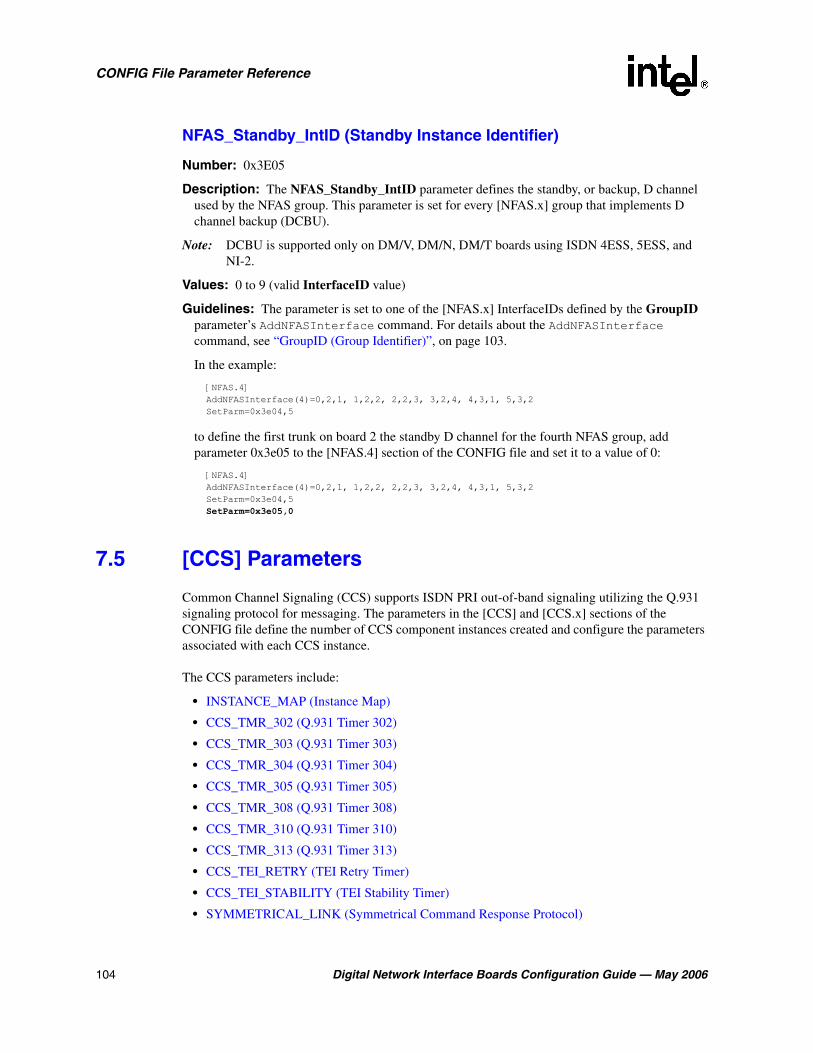
104 Digital Network Interface Boards Configuration Guide — May 2006
CONFIG File Parameter Reference
NFAS_Standby_IntID (Standby Instance Identifier)
Number: 0x3E05
Description: The NFAS_Standby_IntID parameter defines the standby, or backup, D channel used by the NFAS group. This parameter is set for every [NFAS.x] group that implements D channel backup (DCBU).
Note: DCBU is supported only on DM/V, DM/N, DM/T boards using ISDN 4ESS, 5ESS, and NI-2.
Values: 0 to 9 (valid InterfaceID value)
Guidelines: The parameter is set to one of the [NFAS.x] InterfaceIDs defined by the GroupID parameter’s AddNFASInterface command. For details about the AddNFASInterface command, see “GroupID (Group Identifier)”, on page 103.
In the example:
[NFAS.4] AddNFASInterface(4)=0,2,1, 1,2,2, 2,2,3, 3,2,4, 4,3,1, 5,3,2 SetParm=0x3e04,5
to define the first trunk on board 2 the standby D channel for the fourth NFAS group, add parameter 0x3e05 to the [NFAS.4] section of the CONFIG file and set it to a value of 0:
[NFAS.4] AddNFASInterface(4)=0,2,1, 1,2,2, 2,2,3, 3,2,4, 4,3,1, 5,3,2 SetParm=0x3e04,5 SetParm=0x3e05,0
7.5 [CCS] Parameters
Common Channel Signaling (CCS) supports ISDN PRI out-of-band signaling utilizing the Q.931 signaling protocol for messaging. The parameters in the [CCS] and [CCS.x] sections of the CONFIG file define the number of CCS component instances created and configure the parameters associated with each CCS instance.
The CCS parameters include:
• INSTANCE_MAP (Instance Map)
• CCS_TMR_302 (Q.931 Timer 302)
• CCS_TMR_303 (Q.931 Timer 303)
• CCS_TMR_304 (Q.931 Timer 304)
• CCS_TMR_305 (Q.931 Timer 305)
• CCS_TMR_308 (Q.931 Timer 308)
• CCS_TMR_310 (Q.931 Timer 310)
• CCS_TMR_313 (Q.931 Timer 313)
• CCS_TEI_RETRY (TEI Retry Timer)
• CCS_TEI_STABILITY (TEI Stability Timer)
• SYMMETRICAL_LINK (Symmetrical Command Response Protocol)

Digital Network Interface Boards Configuration Guide — May 2006 105
CONFIG File Parameter Reference
• CCS_PROTOCOL_MODE (ISDN Protocol Mode)
• CCS_SWITCH_TYPE (Switch Type)
• L2_TRACE (Layer 2 Access Flag)
INSTANCE_MAP (Instance Map)
Number: 0x05
Description: The INSTANCE_MAP parameter is a bitmap that defines the number of CCS instances created. A CCS instance is created for each network interface that supports common channel signaling. The bitmap’s least significant bit corresponds to the CCS instance associated with the first network interface on the board. The next least significant bit corresponds to the CCS instance associated with the second network interface on the board, and so on. If the bit associated with a network interface has a value of 1, then a CCS instance is created for that network interface. For example, a value of 0x5 (0101) means that CCS instances 1 and 3 are created allowing for common channel signaling on network interfaces 1 and 3.
Values: 0 to 0xffff
CCS_TMR_302 (Q.931 Timer 302)
Number: 0x14
Description: The CCS_TMR_302 parameter is an ISDN Layer 3 timer. For exact timer definitions, refer to the Q.931 specification and the switch specifications.
Note: This parameter only applies to E1 boards.
Values:
• 0: Use the default value for the switch (15000 ms)
• -1: Disable the timer (has the same effect as setting the timer value to 0)
• n > 1: Timer value (milliseconds)
CCS_TMR_303 (Q.931 Timer 303)
Number: 0x0b
Description: The CCS_TMR_303 parameter is an ISDN Layer 3 timer. For exact timer definitions, refer to the Q.931 specification and the switch specifications.
Values:
• 0: Use the default value for the switch (4000 ms)
• -1: Disable the timer (has the same effect as setting the timer value to 0)
• n > 1: Timer value (milliseconds)

106 Digital Network Interface Boards Configuration Guide — May 2006
CONFIG File Parameter Reference
CCS_TMR_304 (Q.931 Timer 304)
Number: 0x0c
Description: The CCS_TMR_304 parameter is an ISDN Layer 3 timer. For exact timer definitions, refer to the Q.931 specification and the switch specifications.
Note: This parameter only applies to E1 boards.
Values:
• 0: Use the default value for the switch (30000 ms)
• -1: Disable the timer (has the same effect as setting the timer value to 0)
• n > 1: Timer value (milliseconds)
CCS_TMR_305 (Q.931 Timer 305)
Number: 0x0d
Description: The CCS_TMR_305 parameter is an ISDN Layer 3 timer. For exact timer definitions, refer to the Q.931 specification and the switch specifications.
Values:
• 0: Use the default value for the switch (4000 ms for T1, 30000 ms for E1)
• -1: Disable the timer (has the same effect as setting the timer value to 0)
• n > 1: Timer value (milliseconds)
CCS_TMR_308 (Q.931 Timer 308)
Number: 0x0e
Description: The CCS_TMR_308 parameter is an ISDN Layer 3 timer. For exact timer definitions, refer to the Q.931 specification and the switch specifications.
Values:
• 0: Use the default value for the switch (4000 ms)
• -1: Disable the timer (has the same effect as setting the timer value to 0)
• n > 1: Timer value (milliseconds)
CCS_TMR_310 (Q.931 Timer 310)
Number: 0x0f
Description: The CCS_TMR_310 parameter is an ISDN Layer 3 timer. For exact timer definitions, refer to the Q.931 specification and the switch specifications.
Values:
• 0: Use the default value for the switch (10000 ms)
• -1: Disable the timer (has the same effect as setting the timer value to 0)
• n > 1: Timer value (milliseconds)

Digital Network Interface Boards Configuration Guide — May 2006 107
CONFIG File Parameter Reference
CCS_TMR_313 (Q.931 Timer 313)
Number: 0x10
Description: The CCS_TMR_313 parameter is an ISDN Layer 3 timer. For exact timer definitions, refer to the Q.931 specification and the switch specifications.
Values:
• 0: Use the default value for the switch (4000 ms)
• -1: Disable the timer (has the same effect as setting the timer value to 0)
• n > 1: Timer value (milliseconds)
CCS_TEI_RETRY (TEI Retry Timer)
Number: 0x15
Description: The CCS_TEI_RETRY parameter defines the maximum amount of time that the data link remains in state 4 (TEI_ASSIGNED) before transitioning to state 5 (TEI_WAIT_ESTABLISH).
Values: Time (milliseconds)
CCS_TEI_STABILITY (TEI Stability Timer)
Number: 0x16
Description: The CCS_TEI_STABILITY parameter defines the minimum transition time between data link state 4 (TEI_ASSIGNED) and data link state 5 (TEI_WAIT_ESTABLISH).
Values: 0 to 100,000 (milliseconds)
SYMMETRICAL_LINK (Symmetrical Command Response Protocol)
Number: 0x13
Description: The SYMMETRICAL_LINK parameter enables or disables symmetrical data link operations.
Values:
• 0: Disable symmetrical data link operations
• 1: Enable symmetrical data link operations
CCS_PROTOCOL_MODE (ISDN Protocol Mode)
Number: 0x17
Description: The CCS_PROTOCOL_MODE parameter sets the network user-side protocol. User-side protocol is also known as TE (terminal emulation) protocol and Network-side protocol

108 Digital Network Interface Boards Configuration Guide — May 2006
CONFIG File Parameter Reference
is also known as NT (network termination) protocol. This parameter also can be used to configure QSIG Master/Slave.
Note: Master/Slave mode pertains to QSIG protocols only.
Note: With the exception of the QSIG protocol (where the User-side and Network-side protocols are symmetrical), using the CSS_PROTOCOL_MODE parameter to configure a Network-side protocol is supported for back-to-back testing purposes only. The Network-side firmware is not fully qualified for operation in a deployment environment.
Values:
• 0: User or Slave Mode (QSIG)
• 1: Network or Master Mode (QSIG)
CCS_SWITCH_TYPE (Switch Type)
Number: 0x07
Description: The CCS_SWITCH_TYPE parameter defines the network switch type.
Values:
• 1: 4ESS
• 2: 5ESS
• 3: DMS
• 4: NTT
• 6: DASS2 (not currently supported)
• 7: NET5
• 10: QSIGE1
• 11: QSIGT1
• 12: NI2
• 13: DPNSS (not currently supported)
L2_TRACE (Layer 2 Access Flag)
Number: 0x09
Description: The L2_TRACE parameter is the ISDN Layer 2 access flag. When Layer 2 (Data Link layer) access is disabled, ISDN Link Access Protocol for the D channel (LAPD) functionality is obtained by accessing ISDN Call Control and Layer 3 (Network layer). When Layer 2 access is enabled, call control is no longer supported for the channels on this line and ISDN LAPD functionality is obtained by accessing Layer 2 directly.
Values:
• 0: Disable Layer 2 access
• 1: Enable Layer 2 access

Digital Network Interface Boards Configuration Guide — May 2006 109
CONFIG File Parameter Reference
7.6 [CHP] Parameters
The Channel Protocol (CHP) component implements the telephony communication protocol that is used on the network interface. The CHP component parameters include:
• R4Compatibility (R4 Compatibility Flag)
• InitialChanState (Initial Channel State)
• DisableBlock (Disable Block)
R4Compatibility (R4 Compatibility Flag)
Number: 0x1310
Description: The R4Compatibility parameter enables or disables R4 (Global Call) compatibility features. This parameter also enables retrieval of DNIS and ANI information in the offered call state.
Values:
• 0: Disable R4 compatibility [default]
• 1: Enable R4 compatibility
• 2: Disable R4 compatibility
InitialChanState (Initial Channel State)
Number: 0x1311
Description: The InitialChanState parameter defines the initial B channel state (CHP channel state) at the end of system initialization. The initial state of the ISDN B channel is either InService or OutOfService. Once the board is initialized, this initial state will be set on all channels of the board until a user application is invoked and explicitly modifies the state of the channel.
Values:
• 1: InService
• 2: OutOfService
Guidelines: This parameter must be set to OutOfService for ISDN protocols.
DisableBlock (Disable Block)
Number: 0x1312
Description: The DisableBlock parameter defines whether or not a blocking pattern (message) is sent on a channel when the channel is in the OutofService state. When DisableBlock is disabled, no pattern is sent (the switch will not present calls to the B channel).
When DisableBlock is enabled and a channel is in the InService state (InitialChanState=1), the protocol will send a non-blocking pattern on the channel (the switch will present calls to the B channel). When DisableBlock is enabled and a channel is in the OutofService state (InitialChanState=2), the protocol will send a blocking pattern on the channel (the switch will

110 Digital Network Interface Boards Configuration Guide — May 2006
CONFIG File Parameter Reference
present calls to the B channel but these calls will be abandoned by the switch since the application will not respond to the call).
Values:
• 0: Disable blocking
• 1: Enable blocking
7.7 [CHP] ISDN Protocol Variant Definitions
The CHP parameters define line configurations. Within the [CHP] section of the CONFIG file, ISDN protocol variants are defined using the Variant Define n command. For a detailed description of the Variant Define n command, see Section 3.4, “[CHP] Section”, on page 29.
The ISDN protocol variant parameters include:
• ProtocolType (Protocol Type)
• InterCallDelay (Inter-call Delay)
• DisconnectTimeout (Disconnect Timeout)
• Layer1Protocol (Layer 1 Protocol)
• InfoTransferRate (Information Transfer Rate)
• InfoTransferCap (Information Transfer Cap)
• CalledNumberType (Called Number Type)
• CalledNumberPlan (Called Number Plan)
• CalledNumberCount (Called Number Count)
• CallingNumberType (Calling Number Type)
• CallingNumberPlan (Calling Number Plan)
• CallingNumberPresentation (Calling Number Presentation)
• CallingNumberScreening (Calling Number Screening)
• CallingNumberCount (Calling Number Count)
• CallProgress (Call Progress)
• CaHdgLoHiGl (Hello Edge/Low Glitch/High Glitch)
• CaAnsdglPSV (Answer Deglitcher/PAMD Speed Value)
• CaHdgLoHiGl (Hello Edge/Low Glitch/High Glitch)
• CaBusySet (Busy Signal)
• CaSitSet (SIT Signal)
• CaFaxSet (Fax Signal)
• CaPvdId (Voice Detection Signal)
• CaPamdId (Answering Machine Signal)
• CaSignalTimeout (Signal Timeout)
• CaAnswerTimeout (Answer Timeout)

Digital Network Interface Boards Configuration Guide — May 2006 111
CONFIG File Parameter Reference
• CaPvdTimeout (Voice Detection Timeout)
ProtocolType (Protocol Type)
Description: The ProtocolType parameter defines the type of ISDN protocol used on a channel. The value of the parameter is dependent on the firmware being downloaded and the CONFIG files used. For example, when downloading the ghmp1_hmpdsb_2_4ess.config file, ProtocolType should be set to a value of 1.
Note: The ProtocolType parameter is also used when defining T1 protocol variants.
Values:
• 1: 4ESS and NI-2
• 2: 5ESS
• 3: DMS100 and DMS250
• 4: NTT
• 7: NET5 and QSIG
InterCallDelay (Inter-call Delay)
Description: The InterCallDelay parameter defines the minimum amount of time between outbound calls.
Note: The InterCallDelay parameter is also used when defining T1 protocol variants.
Values: n > 0 (milliseconds)
DisconnectTimeout (Disconnect Timeout)
Description: The DisconnectTimeout parameter defines the time delay between proceeding and alert/connect. The call will transition to idle after this time period (sooner if ClearConf is received).
Note: The DisconnectTimeout parameter is also used when defining T1 protocol variants.
Values: n > 0 (milliseconds)
Guidelines: None.

112 Digital Network Interface Boards Configuration Guide — May 2006
CONFIG File Parameter Reference
Layer1Protocol (Layer 1 Protocol)
Description: The Layer1Protocol parameter defines the User Layer 1 Protocol.
Values:
• 0x00: Protocol not present
• 0x01: CCITT
• 0x02: G.711 mu-law
• 0x03: G.711 A-law
• 0x04: G.721 ADPCM
• 0x05: G.721 kHz
• 0x06: 384 kHz Video
• 0x07: NS Rate Adaption
• 0x08: V120 Rate Adaption
• 0x09: X.31 HDLC
InfoTransferRate (Information Transfer Rate)
Description: The InfoTransferRate parameter defines the information transfer rate.
Values:
• 0x00: Rate undefined
• 0x10: 64 kbps
• 0x11: 128 kbps
• 0x13: 384 kbps
• 0x15: 1536 kbps
• 0x17: 1920 kbps
• 0x18: Multi-rate
InfoTransferCap (Information Transfer Cap)
Description: The InfoTransferCap parameter defines the information transfer capability.
Values:
• 0x00: Speech
• 0x08: Unrestricted digital
• 0x09: Restricted digital
• 0x10: 3 kHz
• 0x11: 7 kHz
• 0x18: Video

Digital Network Interface Boards Configuration Guide — May 2006 113
CONFIG File Parameter Reference
CalledNumberType (Called Number Type)
Description: The CalledNumberType parameter defines the type of outbound calls (Called Party Numbers).
Values:
• 0x00: Unknown
• 0x01: International
• 0x02: National
• 0x03: Network specific
• 0x04: Network subscriber
• 0x06: Network abbreviated
CalledNumberPlan (Called Number Plan)
Description: The CalledNumberPlan parameter defines the numbering plan to use for outbound calls (Called Party Numbers).
Values:
• 0x00: Unknown
• 0x01: ISDN
• 0x02: Telephony
• 0x03: Date X.121
• 0x04: Telex F.69
• 0x08: National standard
• 0x09: Private
CalledNumberCount (Called Number Count)
Description: The CalledNumberCount parameter defines the number of digits to collect from an incoming call.
Values:
• 0: Collect all the digits provided
• n: Number of digits to collect

114 Digital Network Interface Boards Configuration Guide — May 2006
CONFIG File Parameter Reference
CallingNumberType (Calling Number Type)
Description: The CallingNumberType parameter defines the type of outbound call (Calling Party Number).
Values:
• 0x00: Unknown
• 0x01: International
• 0x02: National
• 0x03: Network specific
• 0x04: Network subscriber
• 0x06: Network abbreviated
CallingNumberPlan (Calling Number Plan)
Description: The CallingNumberPlan parameter defines the numbering plan to use for outbound calls (Calling Party Numbers).
Values:
• 0x00: Unknown
• 0x01: ISDN
• 0x02: Telephony
• 0x03: Date X.121
• 0x04: Telex F.69
• 0x08: National standard
• 0x09: Private
CallingNumberPresentation (Calling Number Presentation)
Description: The CallingNumberPresentation parameter defines the presentation for calling number (outbound calls).
Values:
• 0x00: Allowed
• 0x01: Restricted
• 0x02: Not available
CallingNumberScreening (Calling Number Screening)
Description: The CallingNumberScreening parameter defines the screening for calling number (outbound calls).
Values:
• 0x00: User provided
• 0x01: Verified and passed
• 0x02: Verified and failed
• 0x03: Network provided

Digital Network Interface Boards Configuration Guide — May 2006 115
CONFIG File Parameter Reference
CallingNumberCount (Calling Number Count)
Description: The CallingNumberCount parameter defines the number of Calling Party Number digits to collect from incoming call.
Values:
• 0: Collect all the digits provided
• n: Number of digits to collect
CallProgress (Call Progress)
Description: The CallProgress parameter enables or disables call progress detection for call setup.
Note: The CallProgress parameter is also used when defining T1 protocol variants.
Values:
• y: Enable call progress detection
• n: Disable call progress detection
CaHdgLoHiGl (Hello Edge/Low Glitch/High Glitch)
The CaHdgLoHiGl parameter combines three parameters into one. They include the Hello Edge, Low Glitch, and High Glitch parameters. The values for all three parameters are contained in the CaHdgLoHiGl parameter value, 0xFF020F13, where 02 is the default hexadecimal value (2 decimal) for the Hello Edge parameter, 0F is the default hexadecimal value (15 decimal) for the Low Glitch parameter, and 13 is the hexadecimal value (19 decimal) for the High Glitch parameter.
Description: The Hello Edge parameter defines the point at which a connect will be returned to the application.
Values:
• 1: Rising edge (immediately when a connect is detected)
• 2: Falling edge (after the end of the salutation)
Description: The Low Glitch parameter defines, in intervals of 10 milliseconds, the maximum silence period to ignore. This maximum silence period helps to eliminate spurious silence intervals.
Values: The default value is 15 decimal (150 milliseconds).
Description: The High Glitch parameter defines, in intervals of 10 milliseconds, the maximum nonsilence period to ignore. This maximum nonsilence period helps to eliminate spurious nonsilence intervals.
Values: The default value is 19 decimal (190 milliseconds).
CaAnsdglPSV (Answer Deglitcher/PAMD Speed Value)
The CaAnsdglPSV parameter combines two parameters into one. They include the Answer Deglitcher and PAMD Speed Value parameters. The values for both parameters are contained in

116 Digital Network Interface Boards Configuration Guide — May 2006
CONFIG File Parameter Reference
the CaAnsdglPSV parameter value, 0xFFFFFF01, where 01 is the default hexadecimal value (1 decimal) for the PAMD Speed Value parameter and FF is the default hexadecimal value (-1 decimal) for the Answer Deglitcher parameter, which corresponds to disabling it. This parameter should only be enabled if you are concerned with measuring the length of the salutation.
Description: The Answer Deglitcher parameter defines the maximum silence period, in 10 millisecond intervals, allowed between words in a salutation.
Values: The default value is -1 (FFFF), for disabled.
Description: The PAMD Speed Value parameter defines the PAMD algorithm: PAMD_ACCU, PAMD_FULL, and PAMD_QUICK. PAMD_QUICK provides the fastest results based on the connect circumstances, but is the least accurate. PAMD_FULL performs hiss noise analysis to determine if this is an answer machine response, and then performs a full evaluation of the voice response if the hiss information is not sufficient to make the decision. PAMD_ACCU will not perform hiss noise analysis, since this is not required with today’s digital answering systems, but will perform a full answer size voice response to achieve the most accurate result.
Values:
• 1 [default]: PAMD_ACCU
• 2: PAMD_FULL
• 3: PAMD_QUICK
CaRingingSet (Ringing Signal)
Description: The CaRingingSet parameter defines the signal set used to detect ringing for call progress analysis.
Note: The CaRingingSet parameter is also used when defining T1 protocol variants.
Values: 0x024940
CaBusySet (Busy Signal)
Description: The CaBusySet parameter defines the signal set used to detect busy for call progress analysis.
Note: The CaBusySet parameter is also used when defining T1 protocol variants.
Values: 0x004DE0
CaSitSet (SIT Signal)
Description: The CaSiteSet parameter defines the signal set used to detect Special Information Tones (SIT) tones for call progress analysis.
Note: The CaSiteSet parameter is also used when defining T1 protocol variants.
Values: 0x02F240

Digital Network Interface Boards Configuration Guide — May 2006 117
CONFIG File Parameter Reference
CaFaxSet (Fax Signal)
Description: The CaFaxSet parameter defines the signal set used to detect fax tones for call progress analysis.
Note: The CaFaxSet parameter is also used when defining T1 protocol variants.
Values: 0x014B80
CaPvdId (Voice Detection Signal)
Description: The CaPvdId parameter defines the signal to use for positive voice detection in call progress analysis.
Note: The CaPvdId parameter is also used when defining T1 protocol variants.
Values: 0x01F4C1
CaPamdId (Answering Machine Signal)
Description: The CaPamdId parameter defines the signal to use for positive answering machine detection in call progress analysis.
Note: The CaPamdId parameter is also used when defining T1 protocol variants.
Values: 0x01A041
CaSignalTimeout (Signal Timeout)
Description: The CaSignalTimeout parameter defines the maximum amount of time to wait to detect a call progress tone from one of the call analysis signal sets. For T1 loop start and ground start protocols, if this time is exceeded, then the outbound call will fail with the reason being NoAnswer.
Note: The CaSignalTimeout parameter is also used when defining T1 protocol variants.
Values: n > 0 (the value must be a multiple of 10 ms)
CaAnswerTimeout (Answer Timeout)
Description: The CaAnswerTimeout parameter defines the maximum amount of time that call analysis will wait for ringback to stop (equivalent to the number of rings). If this time is exceeded, then the outbound call will fail with the reason being NoAnswer.
Note: The CaAnswerTimeout parameter is also used when defining T1 protocol variants.
Values: n > 0 (the value must be a multiple of 10 ms)
CaPvdTimeout (Voice Detection Timeout)
Description: The CaPvdTimeout parameter defines the maximum amount of time that call analysis will wait to detect positive answering machine detection (PAMD) or positive voice detection (PVD) once ringback has ceased. If this time is exceeded, then the call state will

118 Digital Network Interface Boards Configuration Guide — May 2006
CONFIG File Parameter Reference
transition to “Connected” with the reason being Normal. If PAMD or PVD is detected within this time period, then the “Connected” reason will be PAMD or PVD respectively.
Note: The CaPvdTimeout parameter is also used when defining T1 protocol variants.
Values: n > 0 (the value is expressed in multiples of 10 milliseconds. For example, a value of 200 equals 2000 milliseconds, or 2 seconds)
• For digital boards: default = 400
7.8 [TSC] Parameters
The parameter in the [TSC] section of the CONFIG file is associated with the B channel sets.
Encoding (Encoding Method)
Number: 0x1209
Description: The Encoding parameter defines the encoding method used on a line.
Values:
• 1: A-law
• 2: mu-law
7.9 [TSC] defineBSet Parameters
The parameters defined by the defineBSet command in the [TSC] section of the CONFIG file are associated with the B channel sets. The syntax of the defineBSet command is:
defineBSet = SetId, LineId, StartChan, NumChans, BaseProtocol, Inbound, OutBound, DChanDesc, Admin, Width, BChanId, SlotId, Direction, Count, [BChanId, SlotId, Direction, Count,] 0
Note: The [TSC] defineBSet parameters do not have parameter numbers explicitly defined within the CONFIG file.
The defineBSet parameters include:
• SetId (Set Identifier)
• LineId (Line Identifier)
• StartChan (Start Channel)
• NumChans (Number of B Channels)
• BaseProtocol (Base Protocol)
• Inbound (Inbound Variant)
• Outbound (Outbound Variant)
• DChanDesc (D Channel Identifier)
• Admin (Admin)
• Width (Width)

Digital Network Interface Boards Configuration Guide — May 2006 119
CONFIG File Parameter Reference
• BChanId (B Channel Identifier)
• SlotId (Slot Identifier)
• Direction (Direction)
• Count (Count)
SetId (Set Identifier)
Description: The SetId parameter is an arbitrary identifier set by the user that identifies the B channel set in which the B channels are a member.
Values: Number
Guidelines: Each B channel set must have a unique identifier.
For example, for each line on a board, SetId can be set sequentially to a value that is a multiple of 10 as follows:
defineBSet=10,1,1,23, 0,1,1,1,20,1, 1,1,3,23,0 defineBSet=20,2,1,23, 0,1,1,2,20,1, 1,1,3,23,0 defineBSet=30,3,1,23, 0,1,1,3,20,1, 1,1,3,23,0 defineBSet=40,4,1,23, 0,1,1,4,20,1, 1,1,3,23,0
LineId (Line Identifier)
Description: The LineId parameter defines the T1 or E1 line that carries all of the B channels in the set.
Values: 1 to 16
Guidelines: For example, on a board with four network interfaces, the value of LineId is set to 1 for line 1, 2 for line 2, and so on for each line as follows:
defineBSet=10,1,1,23, 0,1,1,1,20,1, 1,1,3,23,0 defineBSet=20,2,1,23, 0,1,1,1,20,1, 1,1,3,23,0 defineBSet=30,3,1,23, 0,1,1,1,20,1, 1,1,3,23,0 defineBSet=40,4,1,23, 0,1,1,1,20,1, 1,1,3,23,0
StartChan (Start Channel)
Description: The StartChan parameter defines the first B channel in the set. This parameter is used in combination with the NumChans parameter to define a contiguous set of B channels.
Values: The value range depends on the technology, because the number of available B channels varies.
• 1 to 24: T1
• 1 to 30: E1
• 1 to 31: E1 clear channel
Guidelines: For example, on a T1 line where 23 of the 24 channels are used as B channels, the value of StartChan is set to 1 as follows:
defineBSet=10,1,1,23, 0,1,1,1,20,1, 1,1,3,23,0 defineBSet=20,2,1,23, 0,1,1,1,20,1, 1,1,3,23,0 defineBSet=30,3,1,23, 0,1,1,1,20,1, 1,1,3,23,0 defineBSet=40,4,1,23, 0,1,1,1,20,1, 1,1,3,23,0

120 Digital Network Interface Boards Configuration Guide — May 2006
CONFIG File Parameter Reference
NumChans (Number of B Channels)
Description: The NumChans parameter defines the total number of B channels in the set. This parameter is used in combination with the StartChan parameter to define a contiguous set of B channels.
Values: The range of values varies with technology because the number of time slots varies.
• 1 to 24: T1
• 1 to 30: E1
• 1 to 31: E1 clear channel
Guidelines: For example, on a T1 line, a value of 1 for StartChan and a value of 23 for NumChans defines 23 B channels numbered from 1 to 23:
defineBSet=10,1,1,23, 0,1,1,1,20,1, 1,1,3,23,0 defineBSet=20,2,1,23, 0,1,1,2,20,1, 1,1,3,23,0 defineBSet=30,3,1,23, 0,1,1,3,20,1, 1,1,3,23,0 defineBSet=40,4,1,23, 0,1,1,4,20,1, 1,1,3,23,0
BaseProtocol (Base Protocol)
Description: The BaseProtocol parameter defines the base protocol on which the B channel set will run.
Values:
• 0: T1 CAS, ISDN or Global Call protocols (where the default protocol is defined by the firmware) or clear channel
Guidelines: For T1 CAS, ISDN, and Global Call protocols, each firmware load supports only only one base protocol, so this parameter will be set to 0 for these protocols. This parameter is also set to 0 for clear channel. Clear channel is the ability to access telephony channels in the system and configure them to a user-defined call control protocol, or to simply leave the lines “clear”. The resources should have access to the telephony bus for media routing purposes, as well as signal detection, signal generation, and tone generation capabilities, if desired.
For example, on T1 ISDN lines, BaseProtocol is set to a value of 0 as follows:
defineBSet=10,1,1,23, 0,1,1,1,20,1, 1,1,3,23,0 defineBSet=20,2,1,23, 0,1,1,1,20,1, 1,1,3,23,0 defineBSet=30,3,1,23, 0,1,1,1,20,1, 1,1,3,23,0 defineBSet=40,4,1,23, 0,1,1,1,20,1, 1,1,3,23,0
Inbound (Inbound Variant)
Description: The Inbound parameter selects one of the protocol type variant parameter sets defined in the [CHP] section of the CONFIG file to use for inbound calls. The protocol variant defines the type of protocol running on the set of B channels.
Values:
• 0: Clear channel (disable inbound calls)
• n: Variant identifier as defined in the [CHP] section of the CONFIG file
Guidelines: This parameter is set to 0 for clear channel. Clear channel is the ability to access telephony channels in the system and configure them to a user-defined call control protocol, or to

Digital Network Interface Boards Configuration Guide — May 2006 121
CONFIG File Parameter Reference
simply leave the lines “clear”. The resources should have access to the telephony bus for media routing purposes, as well as signal detection, signal generation, and tone generation capabilities, if desired.
For example, on T1 ISDN lines, Inbound is set to a value of 1 as follows:
defineBSet=10,1,1,23, 0,1,1,1,20,1, 1,1,3,23,0 defineBSet=20,2,1,23, 0,1,1,1,20,1, 1,1,3,23,0 defineBSet=30,3,1,23, 0,1,1,1,20,1, 1,1,3,23,0 defineBSet=40,4,1,23, 0,1,1,1,20,1, 1,1,3,23,0
Outbound (Outbound Variant)
Description: The Outbound parameter selects one of the protocol type variant parameter sets defined in the [CHP] section of the CONFIG file to use for outbound calls. The protocol variant defines the type of protocol running on the set of B channels.
Values:
• 0: Clear channels (disable outbound calls)
• n: Variant identifier as defined in the [CHP] section of the CONFIG file
Guidelines: This parameter is set to 0 for clear channel (disable outbound calls). Clear channel is the ability to access telephony channels in the system and configure them to a user-defined call control protocol, or to simply leave the lines “clear”. The resources should have access to the telephony bus for media routing purposes, as well as signal detection, signal generation, and tone generation capabilities, if desired.
For example, on T1 ISDN lines, Outbound is set to a value of 1 as follows:
defineBSet=10,1,1,23, 0,1,1,1,20,1, 1,1,3,23,0 defineBSet=20,2,1,23, 0,1,1,1,20,1, 1,1,3,23,0 defineBSet=30,3,1,23, 0,1,1,1,20,1, 1,1,3,23,0 defineBSet=40,4,1,23, 0,1,1,1,20,1, 1,1,3,23,0
DChanDesc (D Channel Identifier)
Description: The DChanDesc parameter is an ISDN parameter that identifies which trunk the D-channel resides for this B-set. This parameter is ignored for T1 CAS, clear channel, and Global Call protocols.
Values: 1 to 16
Guidelines: For example, on a board with four T1 ISDN lines, DChanDesc is set as follows:
defineBSet=10,1,1,24, 0,1,1,1,20,1, 1,1,3,24,0 defineBSet=20,2,1,24, 0,1,1,2,20,1, 1,1,3,24,0 defineBSet=30,3,1,24, 0,1,1,3,20,1, 1,1,3,24,0 defineBSet=40,4,1,24, 0,1,1,4,20,1, 1,1,3,24,0
Admin (Admin)
Description: The Admin parameter is an arbitrary 32-bit value set by the user that is exported to the TSC_AttrAdminGroup attribute of the TSC cluster for each B channel in the set. This attribute can be used to find and/or allocate TSC clusters.
Values: 0 to 0xFFFFFFFF
Guidelines: For example, on a T1 line, Admin is set to a value of 20 as follows:
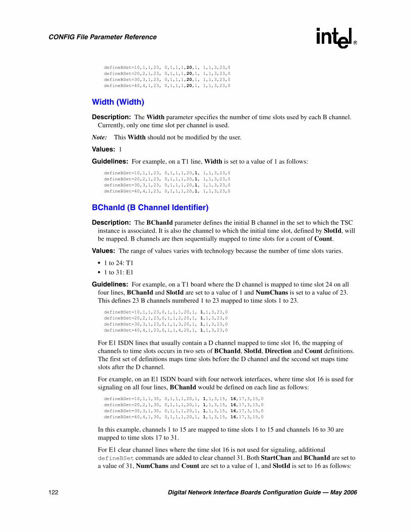
122 Digital Network Interface Boards Configuration Guide — May 2006
CONFIG File Parameter Reference
defineBSet=10,1,1,23, 0,1,1,1,20,1, 1,1,3,23,0 defineBSet=20,2,1,23, 0,1,1,1,20,1, 1,1,3,23,0 defineBSet=30,3,1,23, 0,1,1,1,20,1, 1,1,3,23,0 defineBSet=40,4,1,23, 0,1,1,1,20,1, 1,1,3,23,0
Width (Width)
Description: The Width parameter specifies the number of time slots used by each B channel. Currently, only one time slot per channel is used.
Note: This Width should not be modified by the user.
Values: 1
Guidelines: For example, on a T1 line, Width is set to a value of 1 as follows:
defineBSet=10,1,1,23, 0,1,1,1,20,1, 1,1,3,23,0 defineBSet=20,2,1,23, 0,1,1,1,20,1, 1,1,3,23,0 defineBSet=30,3,1,23, 0,1,1,1,20,1, 1,1,3,23,0 defineBSet=40,4,1,23, 0,1,1,1,20,1, 1,1,3,23,0
BChanId (B Channel Identifier)
Description: The BChanId parameter defines the initial B channel in the set to which the TSC instance is associated. It is also the channel to which the initial time slot, defined by SlotId, will be mapped. B channels are then sequentially mapped to time slots for a count of Count.
Values: The range of values varies with technology because the number of time slots varies.
• 1 to 24: T1
• 1 to 31: E1
Guidelines: For example, on a T1 board where the D channel is mapped to time slot 24 on all four lines, BChanId and SlotId are set to a value of 1 and NumChans is set to a value of 23. This defines 23 B channels numbered 1 to 23 mapped to time slots 1 to 23.
defineBSet=10,1,1,23,0,1,1,1,20,1, 1,1,3,23,0 defineBSet=20,2,1,23,0,1,1,2,20,1, 1,1,3,23,0 defineBSet=30,3,1,23,0,1,1,3,20,1, 1,1,3,23,0 defineBSet=40,4,1,23,0,1,1,4,20,1, 1,1,3,23,0
For E1 ISDN lines that usually contain a D channel mapped to time slot 16, the mapping of channels to time slots occurs in two sets of BChanId, SlotId, Direction and Count definitions. The first set of definitions maps time slots before the D channel and the second set maps time slots after the D channel.
For example, on an E1 ISDN board with four network interfaces, where time slot 16 is used for signaling on all four lines, BChanId would be defined on each line as follows:
defineBSet=10,1,1,30, 0,1,1,1,20,1, 1,1,3,15, 16,17,3,15,0 defineBSet=20,2,1,30, 0,1,1,1,20,1, 1,1,3,15, 16,17,3,15,0 defineBSet=30,3,1,30, 0,1,1,1,20,1, 1,1,3,15, 16,17,3,15,0 defineBSet=40,4,1,30, 0,1,1,1,20,1, 1,1,3,15, 16,17,3,15,0
In this example, channels 1 to 15 are mapped to time slots 1 to 15 and channels 16 to 30 are mapped to time slots 17 to 31.
For E1 clear channel lines where the time slot 16 is not used for signaling, additional defineBSet commands are added to clear channel 31. Both StartChan and BChanId are set to a value of 31, NumChans and Count are set to a value of 1, and SlotId is set to 16 as follows:

Digital Network Interface Boards Configuration Guide — May 2006 123
CONFIG File Parameter Reference
defineBSet=50,1,31,1, 0,0,0,1,21,1, 31,16,3,1,0 defineBSet=60,2,31,1, 0,0,0,1,21,1, 31,16,3,1,0 defineBSet=70,3,31,1, 0,0,0,1,21,1, 31,16,3,1,0 defineBSet=80,4,31,1, 0,0,0,1,21,1, 31,16,3,1,0
SlotId (Slot Identifier)
Description: The SlotId parameter defines the logical time slot the initial B channel, defined by BChanId, is using. B channels are then sequentially mapped to time slots for a count of Count.
Values: The range of values varies with technology because the number of time slots varies.
• 1 to 24: T1
• 1 to 31: E1 ISDN
• 1 to 31: E1 clear channel
Guidelines: For E1 ISDN, the mapping of channels to time slots occurs in two sets of BChanId, SlotId, Direction and Count definitions. The first set of definitions maps the time slots before the D channel, and the second set maps the slots after the D channel.
For example, on an E1 ISDN board with four network interfaces, where time slot 16 is used for signaling on all four lines, SlotId for all four lines would be as follows
defineBSet=10,1,1,30, 0,1,1,1,20,1, 1,1,3,15, 16,17,3,15,0 defineBSet=20,2,1,30, 0,1,1,1,20,1, 1,1,3,15, 16,17,3,15,0 defineBSet=30,3,1,30, 0,1,1,1,20,1, 1,1,3,15, 16,17,3,15,0 defineBSet=40,4,1,30, 0,1,1,1,20,1, 1,1,3,15, 16,17,3,15,0
For all lines in this example, channels 1 to 15 are sequentially mapped to time slots 1 to 15 and channels 16 to 30 are mapped to time slots 17 to 31.
For E1 clear channel lines where time slot 16 is not used for signaling, additional defineBSet commands are added to clear channel 31 and to map time slot 16. Both StartChan and BChanId are set to a value of 31, NumChans and Count are set to a value of 1, and SlotId is set to 16 as follows:
defineBSet=50,1,31,1, 0,0,0,1,21,1, 31,16,3,1,0 defineBSet=60,2,31,1, 0,0,0,1,21,1, 31,16,3,1,0 defineBSet=70,3,31,1, 0,0,0,1,21,1, 31,16,3,1,0 defineBSet=80,4,31,1, 0,0,0,1,21,1, 31,16,3,1,0
Direction (Direction)
Description: The Direction parameter defines the direction in which the data can be sent: inbound, outbound, or both.
Values:
• 1: Inbound
• 2: Outbound
• 3: Both
Guidelines: For example, on an T1 line where data is transferred both inbound and outbound, Direction is set to a value of 3 as follows:
defineBSet=10,1,1,23, 0,1,1,1,20,1, 1,1,3,23,0 defineBSet=20,2,1,23, 0,1,1,2,20,1, 1,1,3,23,0 defineBSet=30,3,1,23, 0,1,1,3,20,1, 1,1,3,23,0 defineBSet=40,4,1,23, 0,1,1,4,20,1, 1,1,3,23,0

124 Digital Network Interface Boards Configuration Guide — May 2006
CONFIG File Parameter Reference
Count (Count)
Description: The Count parameter defines the number of time slots that are being mapped to B channels. This value is limited to the value of NumChans since only the number of channels that exist on a line can be mapped to a time slots.
Values: 1 to NumChans
Guidelines: For example, on a T1 line containing two network interfaces, where time slot 24 is used as a D channel on both lines, the Count for both lines would be as follows:
defineBSet=10,1,1,23, 0,1,1,1,20,1, 1,1,3,23,0 defineBSet=20,2,1,23, 0,1,1,1,20,1, 1,1,3,23,0
For an E1 line, Count is set to a value of 30 for lines that contain only B channels. For lines that contain a single D channel, the mapping of channels to time slots occurs in two sets of BChanId, SlotId, Direction and Count definitions. The first set of definitions maps the time slots before the D channel, and the second set maps the slots after the D channel. For example, on an E1 board with four network interfaces, where time slot 16 is used for signaling on all four lines, the Count for all four lines would be as follows:
defineBSet=10,1,1,30, 0,1,1,1,20,1, 1,1,3,15, 16,17,3,15,0 defineBSet=20,2,1,30, 0,1,1,1,20,1, 1,1,3,15, 16,17,3,15,0 defineBSet=30,3,1,30, 0,1,1,1,20,1, 1,1,3,15, 16,17,3,15,0 defineBSet=40,4,1,30, 0,1,1,1,20,1, 1,1,3,15, 16,17,3,15,0
For all lines in this example, channels 1 to 15 are mapped to time slots 1 to 15 and channels 16 to 30 are mapped to time slots 17 to 31.
For E1 clear channel lines where the time slot 16 is not used for signaling, additional defineBSet commands are added to clear channel 31 and to map time slot 16. Count is set to a value of 1 (also the value of NumChans) as follows:
defineBSet=50,1,31,1, 0,0,0,1,21,1, 31,16,3,1,0 defineBSet=60,2,31,1, 0,0,0,1,21,1, 31,16,3,1,0 defineBSet=70,3,31,1, 0,0,0,1,21,1, 31,16,3,1,0 defineBSet=80,4,31,1, 0,0,0,1,21,1, 31,16,3,1,0

Digital Network Interface Boards Configuration Guide — May 2006 125
Glossary
4ESS: A T1 protocol switch primarily used for switching digital voice, but it also supports ISDN protocols.
5ESS: A T1 protocol switch used for switching digital voice and data channels, and supports both basic rate and primary rate ISDN.
AGC: Automatic Gain Control is an encoding process that attempts to maintain a constant volume during voice recording.
alternate mark inversion: See AMI.
AMI: Alternate mark inversion is a form of bipolar signaling in which each successive mark is of the opposite polarity and spaces have zero amplitude.
Automatic Gain Control: See AGC.
base protocol: The protocol implemented by the CHP component. Protocol variants are derived from this base. Compare with protocol variant.
B channel: An ISDN bearer channel that carries voice, fax and compressed video.
bridge controller: A component that manages the media stream connections between Intel NetStructure® digital network interface boards connected to the CT Bus and HMP.
bridge device: A component on an Intel NetStructure® digital network interface board that enables media streaming between the boards connected to the CT Bus and HMP. The bridge device also provides clocking to HMP.
CAS: Channel Associated Signaling is the component responsible for managing the generation and detection of digital line signaling functions required to manage voice channels. Channel Associated Signaling also applies to a signaling method in which the signaling for that channel is directly associated with the channel.
CCS: Common Channel Signaling is the component that applies to technologies such as ISDN that use common channel signaling. Common Channel Signaling also applies, in general, to a signaling method in which the signaling for a group of channels is carried on a separate (common) channel.
CDP: Country Dependent Parameters file defining parameters necessary for configuring products to different country requirements. This file has a .cdp extension.
CEPT: European Conference of Postal and Telecommunications Administrations. A group of European countries organized for the purpose of setting telecommunications standards in Europe.
CFA: Carrier-Failure Alarm.
CHP: Channel Protocol is the component responsible for implementing the telephony communication protocol that is used on each network interface.

126 Digital Network Interface Boards Configuration Guide — May 2006
clear channel: A signaling configuration where none of the line’s bandwidth is used for signaling. Clear channel signaling is the ability to access telephony channels in the system and configure them to a user defined call control protocol, or to simply leave the lines ‘clear’. The resources should have access to the telephony bus for media routing purposes, as well as signal detection, signal generation, and tone generation capabilities, if desired. NFAS is an example of clear channel signaling.
clock master: The device (board) that provides timing to all other devices attached to the TDM bus. The clock master drives bit and framing clocks for all of the other boards (slaves) in the system.
cluster: A collection of component instances that share specific TDM time slots on the network interface and which therefore operate on the same media stream data. The cluster concept in the Intel® Dialogic® architecture corresponds generally but not exactly to the concept of a “group” in S.100 or to a “channel” in conventional Dialogic architectural terminology. Component instances are bound to a particular cluster and its assigned time slots in an allocation operation.
CNG: Comfort Noise Generation.
CONFIG: A text-input configuration file containing component-specific parameters. This file has a .config extension and is used to create an FCD file.
configuration file: See CONFIG file.
configuration file set: A set of files associated with a specific board configuration. All the files in the set have the same name, but different extensions. The set includes the CONFIG, FCD, and PCD files.
Country Dependent Parameters: See CDP.
CRC: Cyclic Redundancy Check.
CT Bus: Computer Telephony bus. A time division multiplexing communications bus that provides 4096 time slots for transmission of digital information between CT Bus products. See TDM bus.
D channel: An ISDN channel that carries signaling information.
D4: A T1 protocol switch that supports T1 robbed bit signaling and provides D4 framing, but does not support ISDN protocols.
DCM: Configuration Manager - a software program that allows you to configure system-level and certain board-level parameters.
DM3: An architecture on which a whole set of Intel telecom products is built. The DM3 architecture is open, layered, and flexible, encompassing hardware as well as software components.
DMA: Direct memory access.
DMS: A T1 protocol switch (DMS-100) for primary rate ISDN applications.
Driver property sheet: DCM property sheet that contains parameters to optimize the board’s throughput by customizing certain aspects of the board’s device driver.

Digital Network Interface Boards Configuration Guide — May 2006 127
DTD: Dial Tone Detection.
DTMF: Dual Tone Multi-Frequency. Touchtone dialing.
E&M: Two-way telephony signaling that uses an “E” (far end) lead and an “M” (near-end) lead. Signaling is accomplished by applying -48 volts DC to the leads.
encoder: The component responsible for performing an encoding process on a media stream.
FCD: Feature Configuration Description file that lists any non-default parameter settings that are necessary to configure a hardware/firmware product for a particular feature set. This file has a .fcd extension.
Feature Configuration Description: See FCD.
flexible routing: A routing configuration where the resource devices (voice/fax) and network interface devices are independent, which allows exporting and sharing of the resources. All resources have access to the CT Bus.
FRU: Field replaceable unit.
FXO: Foreign Exchange Office - a device at a central site that permits extending PBX services to remote sites. The FXO emulates a phone to the PBX.
FXS: Foreign Exchange Station - a device located remotely from a PBX that permits extending PBX services to remote sites. The FXS emulates a PBX to the remote phone.
ground start: A two-way, two-wire (tip and ring) signaling method similar to loop start in which the current flows in a circuit. Ground start is normally between a PBX and central office and seizure of the line is accomplished by momentarily grounding one of the circuit wires, usually the ring of the tip and ring circuit.
HDB3: A modified AMI signaling code that only applies to E1 and is used to preserve one’s density on the line.
high density bipolar three zero: See HDB3.
in-band signaling: A signaling scheme where both the data and the signaling information for the data are carried over the same channels.
instance: A component instance is an addressable unit within the software architecture; it represents a single thread of control. The system resource management and messaging services operate at the instance level. A set of component instances that make up a resource instance communicate with one another using the system messaging services. A set of component instances is usually associated with a channel of call processing.
IPVS: IP Voice Streaming
ISDN: Integrated Services Digital Network. See primary rate ISDN.
LAPD: Link Access Protocol for the D channel.
Layer 1: Physical layer of the OSI model that address the physical aspects of network access.
Layer 2: Data Link layer of the OSI model that address data transfer and routing.

128 Digital Network Interface Boards Configuration Guide — May 2006
Layer 3: Network layer of the OSI model that addresses line communication procedures.
LCON: See LineAdmin.
LineAdmin: Line Administration component responsible for managing line devices.
LOF: Loss of frame.
Logical property sheet: DCM property sheet that contains parameters for configuring a board’s trunk interface.
LOS: Loss of signal.
loop start: A two-way, two-wire (tip and ring) signaling method in which the current used for signaling flows in a circuit (loop) between a telephone and PBX or a telephone and central office. Seizure of the line is accomplished by going off-hook which causes current to flow in a circuit (loop).
LOF: Loss of Frame.
media loads: Pre-defined, numbered sets of features supported by DM3 architecture boards.
MF: Multi-Frequency
Misc property sheet: DCM property sheet that contains the parameters that define the configuration file set for the board (PCDFileName and FCDFileName), as well as, system-level and miscellaneous parameters.
MLM: Load Module.
Net5: An E1 protocol switch. Net5 is a European ISDN primary rate switch.
NFAS: Non-Facility-Associated Signaling is a form of out-of-band signaling where a single ISDN primary rate D channel provides signaling and control for up to 10 ISDN primary rate lines.
NI-2: National ISDN-2. A U.S. standard software interface that can be installed on most switch types, providing maximum interoperability with ISDN lines.
NIC: Network interface card.
NTT: A T1 protocol switch (INS-Net 1500) that is used by Nippon Telephone and Telegraph (NTT) for primary rate ISDN.
on-hook: The signaling state that occurs when a handset is sitting on the phone (the phone’s inactive state) and the flash hook is depressed. Compare with off-hook.
off-hook: The signaling state that occurs when the handset is removed from the phone and the flash hook is released. When a phone is taken off-hook it signals the central office or PBX that it needs attention, for example, to make a call or to answering an incoming call. Compare with on-hook.
OSI: Open Standards Interconnections. ISO-developed open standards-based framework for inter-system communications. The OSI model categorizes the communication process into seven layers. Layers 1 to 4 address network access and Layers 5 to 7 address messaging.

Digital Network Interface Boards Configuration Guide — May 2006 129
out-of-band signaling: A signaling scheme where the signaling is carried over channels separate from the channels carrying the data.
PAMD: Positive answering machine detection.
PBLM: Processor Boot Load Module.
PBX: Private Branch Exchange.
PCD: Product Configuration Description file that contains product or platform configuration description information. This file has a .pcd extension.
PCM: Pulse Code Modulation.
PDK: Protocol Development Kit.
PDK Configuration property sheet: DCM property sheet that contains parameters for assigning country dependent parameter (CDP) files to T1 trunks that use the CAS protocol or to E1 trunks that use the R2MF protocol.
Physical property sheet: DCM property sheet that contains parameters that relate to the physical aspects of the board including physically identifying the board.
PLM: Processor Load Module.
port: A logical entity that represents the point at which PCM data can flow into or out of a component instance or interface in a cluster. The port abstraction provides a high-level means of defining potential data flow paths within clusters and controlling the actual data flow using simple protocols. Ports are classified and designated in terms of data flow direction and the type of entity that provides the port.
primary D channel: the D channel that provides the signaling and control in an NFAS configuration.
primary rate ISDN: An application that uses a single channel to carry the signaling for all other channels on a line. On a T1 line, the application uses channels 1 through 23 (B channels) to carry data, digital voice, and compressed video. Channel 24 (D channel) carries the signaling for all 23 B channels. On an E1 line, the application uses channels 1 through 15 and 17 through 31 (B channels) to carry data, digital voice, and compressed video. Channel 16 (D channel) carries the signaling for all 30 B channels.
Product Configuration Description: See PCD.
property sheet: A grouping of parameters in DCM that is based on functionality.
protocol variant: A version of the base protocol that has been customized by a set of parameters. This parameter set configures a CHP component to support a particular T1 telephony protocol. Features such as wink start, DTMF DNIS and MF ANI are enabled and tuned by the parameters in a protocol variant. Compare with base protocol.
pulse: A temporary state change from the current signal state to a new signaling state, and then back to the original signaling state. Compare with sequence, train and transition.
PVD: Positive voice detection.

130 Digital Network Interface Boards Configuration Guide — May 2006
Q.931: Primary rate ISDN D channel signaling protocol standard. (ITU-T Recommendation I.451). The protocol defines the signaling packet, including message type and content, and allows for voice and data transfer on a single trunk.
QSIG: A T1 and E1 protocol switch. QSIG is an ISDN signaling and control protocol used for communications between two or more Private Integrated Network Exchange applications (PSS1). The signaling protocol for this standard is defined by Q.931.
R2MF: An E1 protocol switch. R2MF is an in-band common channel signaling protocol that uses channel 16 to convey the signaling for the 30 voice channels. This international signaling system is used mostly in Europe and Asia in non-ISDN applications to permit the transmission of numerical and other information relating to the called and calling subscriber lines.
RAI: Remote Alarm Indication.
Rate Adaption: Conversion of digital data into a different transfer speed (rate) and form.
recorder: The component responsible for a resource’s message exchanges with the host, as well as media stream management and encoder component control functions.
red alarm: An alarm generated by the device at the receiving end of a T1 or E1 line to report a loss of signal or frame alignment (synchronization) in the signal being received (incoming data).
resource: A conceptual entity that provides a specific functionality to a host application. A resource contains a well defined interface or message set, which the host application utilizes when accessing the resource. Resource firmware consists of multiple components that run on top of the core platform software (which includes the platform-specific DM3 kernel and device driver). The Global Call resource is an example of such a resource, providing all of the features and functionality necessary for handling calls on the platform.
sequence: A set of train signals. Compare with pulse, train and transition.
SIT: Special Information Tones
slave: Device (board) that is not a clock master, but instead, derives its timing from the TDM bus.
system tray: In a Windows* operating system, an area of the interface (normally in the lower, right-hand corner) that contains icons, or short cuts, for launching applications.
TDM: Time division multiplexing.
TDM bus: Time division multiplexing bus. A resource sharing bus such as the SCbus or CT Bus that allows information to be transmitted and received among resources over multiple data lines.
TDM Bus Configuration property sheet: DCM property sheet that contains parameters for configuring the TDM bus.
TEI: Terminal Endpoint Identifier. TEI defines which device(s) attached to a BRI ISDN line is communicating with the CO.
Telephony Bus property sheet: (CM property sheet for setting PCM encoding method and bus type.

Digital Network Interface Boards Configuration Guide — May 2006 131
time division multiplex: A multiplexing scheme in which a number of low speed digital signals are incorporated onto a high speed line in a byte-interleave pattern.
train: A set of transitions from one signaling state to another in a predefined pattern (set of pulses). Compare with pulses, sequence and transition.
transition: A permanent state change from the current signal state to a new signaling state. Compare with pulse, sequence and train.
Trunk Configuration property sheet: DCM property sheet for configuring network interfaces on certain Intel NetStructure boards.
TS16: An E1 protocol switch. TS16 is a type of clear channel signaling which allows time slot 16 to be used for data instead of signaling.
TSC: Telephony Service Component is the component responsible for managing the B channel sets.
Version Info. DCM property sheet that contains parameters that identify control processor and signal processor kernel versions.
VAD: Voice Activity Detection.
yellow alarm: An alarm generated by the device at the receiving end of a T1 or E1 line and sent to the device at the transmitting (remote) end to signify that a red alarm condition exists at the receiving (local) end. The yellow alarm is sent to the transmitting device as long as the red alarm condition exists at the receiving end.

132 Digital Network Interface Boards Configuration Guide — May 2006

Digital Network Interface Boards Configuration Guide — May 2006 133
Numerical Index of Parameters
0x05. . . . . . . . . . . . . . . . . . . . 105
0x07. . . . . . . . . . . . . . . . . . . . 108
0x09. . . . . . . . . . . . . . . . . . . . 108
0x0b. . . . . . . . . . . . . . . . . . . . 105
0x0c . . . . . . . . . . . . . . . . . . . . 106
0x0d. . . . . . . . . . . . . . . . . . . . 106
0x0e . . . . . . . . . . . . . . . . . . . . 106
0x0f . . . . . . . . . . . . . . . . . . . . 106
0x10. . . . . . . . . . . . . . . . . . . . 107
0x13. . . . . . . . . . . . . . . . . . . . 107
0x14. . . . . . . . . . . . . . . . . . . . 105
0x15. . . . . . . . . . . . . . . . . . . . 107
0x16. . . . . . . . . . . . . . . . . . . . 107
0x17. . . . . . . . . . . . . . . . . . . . 107
0x1209. . . . . . . . . . . . . . . . . . 118
0x1310. . . . . . . . . . . . . . . . . . 109
0x1311. . . . . . . . . . . . . . . . . . 109
0x1312. . . . . . . . . . . . . . . . . . 109
0x1601. . . . . . . . . . . . . . . . . . 94
0x1602. . . . . . . . . . . . . . . . . . 94
0x1603. . . . . . . . . . . . . . . . . . 95
0x1604. . . . . . . . . . . . . . . . . . 96
0x1609. . . . . . . . . . . . . . . . . . 97
0x160a . . . . . . . . . . . . . . . . . . 97
0x160b. . . . . . . . . . . . . . . . . . 98
0x160c . . . . . . . . . . . . . . . . . . 97
0x160d. . . . . . . . . . . . . . . . . . 97
0x160e . . . . . . . . . . . . . . . . . . 98
0x160f . . . . . . . . . . . . . . . . . . 98
0x1610. . . . . . . . . . . . . . . . . . 98
0x1611. . . . . . . . . . . . . . . . . . 98
0x1624. . . . . . . . . . . . . . . . . . 96
0x1625. . . . . . . . . . . . . . . . . . 99
0x1626. . . . . . . . . . . . . . . . . . 99
0x1639. . . . . . . . . . . . . . . . . . 100
0x163a . . . . . . . . . . . . . . . . . . 100
0x163b. . . . . . . . . . . . . . . . . . 100
0x163c . . . . . . . . . . . . . . . . . . 101
0x163d. . . . . . . . . . . . . . . . . . 101
0x2c03. . . . . . . . . . . . . . . . . . 92
0x3e00. . . . . . . . . . . . . . . . . . 103
0x3e02. . . . . . . . . . . . . . . . . . 102
0x3e04. . . . . . . . . . . . . . . . . . 103
0x3e05. . . . . . . . . . . . . . . . . . 104

134 Digital Network Interface Boards Configuration Guide — May 2006

Digital Network Interface Boards Configuration Guide — May 2006 135
Index
Symbols[0x2c] CONFIG file section 28, 92
[CCS] CONFIG file section 28, 104
[CHP] CONFIG file section 28, 29, 109
[CHP] ISDN Protocol CONFIG file section 110
[lineAdmin] CONFIG file section 28, 93
[NFAS] CONFIG file section 28, 101
[TSC] CONFIG file section 28, 30, 118
[TSC] defineBSet CONFIG file section 118
AA Law
encoding parameter 118Layer 1 Protocol 112
accessing property sheets 16
acoustic echo 49
Admin parameter 121
AdministrativeStatus parameter 72
ADPCM Layer 1 Protocol 112
alternate mark inversion (AMI) 95, 96
Answer Deglitcher parameter 116
Answer Timeout parameter 117
Answering Machine Signal parameter 117
Attached to TDM Buses parameter 78
BB Channel Identifier parameter 122
B channel setdefineBSet command 30parameters 118-124
B8ZS 95
BaseProtocol parameter 120
BChanId parameter 122
Bell zero code suppression 96
blocking pattern 109
Board monitoring frequency in seconds parameter 69
BoardEnabled parameter 70
BoardPresent parameter 70
boardsconfiguration files 36
BPVS Threshold Range parameter 100
bridge controllermodifying parameters 41parameters 61property sheet (illustrated) 20
bridge devicemodifying parameters 39parameters 62property sheet (illustrated) 19
BridgeControllerNumberOfHSIHOLDBuffers parameter 62
BridgeDeviceBHStreamCapacity parameter 65
BridgeDeviceEnabled parameter 63
BridgeDeviceHBStreamCapacity parameter 65
BridgeDeviceHMPClockMaster parameter 64
BridgeDeviceHMPClockMasterFallbackNbrResolved parameter 64
BridgeDeviceHMPClockMasterFallbackNbrUserDefined parameter 64
BridgeDeviceId parameter 63
BridgeDeviceMaxBHStreamSetting parameter 65
BridgeDeviceMaxHBStreamSetting parameter 65
BridgeDeviceMultiBridgeSynchPattern parameter 66
BridgeDeviceStatus parameter 64
BridgeDeviceType parameter 63
bus companding methodsetting for DM3 configurations 42
Busy Signal parameter 116
CCaAnsdglPSV parameter 115
CaAnswerTimeout parameter 117
CaBusySet parameter 116
CaFaxSet parameter 117
CaHdgLoHiGl parameter 115
Call Progress Flag parameter 115
CalledNumberCount parameter 113
CalledNumberPlan parameter 113
CalledNumberType parameter 113
CallingNumberCount parameter 115
CallingNumberPlan parameter 114
CallingNumberPresentation parameter 114
CallingNumberScreening parameter 114
CallingNumberType parameter 114

136 Digital Network Interface Boards Configuration Guide — May 2006
CallProgress parameter 115
CaPamdId parameter 117
CaPvdId parameter 117
CaPvdTimeout parameter 117
CaRingingSet parameter 116
CASconfiguring 28, 91setting signaling type 94
CaSignalTimeout parameter 117
CaSitSet parameter 116
CCSCONFIG file section 28parameters 104-108
CCS_PROTOCOL_MODE parameter 107
CCS_SWITCH_TYPE parameter 108
CCS_TEI_RETRY parameter 107
CCS_TEI_STABILITY parameter 107
CCS_TMR_302 parameter 105
CCS_TMR_303 parameter 105
CCS_TMR_304 parameter 106
CCS_TMR_305 parameter 106
CCS_TMR_308 parameter 106
CCS_TMR_310 parameter 106
CCS_TMR_313 parameter 107
CECS Threshold Range parameter 101
CFA parametersRAI CRC 98RAICRCCFAClearTime 98RAICRCCFADeclareTime 98red alarm 97, 98REDCFAClearedTime 98REDCFADecay 97REDCFADeclareTime 97yellow alarm 98YellowCFAClearTime 98YellowCFADeclareTime 98
channel densities 23
Channel Protocol. See CHP
channel set. See B channel set
channel state 109
CHPCONFIG file section 28, 29ISDN protocol variants 110-118parameters 109-110
clear channelSee also defineBSet parameterssetting signaling type 95
clock fallbackHMP 24
clock fallback concepts 23
clock sourcesetting for H.100 and H.110 mode systems (CT Bus) 38
clockingCT Bus 23HMP 24
Coding parameter 95
commentsCONFIG file 28
Common Channel Signaling. See CCS
Computer Name Dialog box 35
conferencing device, echo cancellation 55
CONFIG file 21[CHP] section 29[NFAS] section 28[TSC] section 30editing 44formatting conventions 27 See also configuration file sets
configurationDCM property sheet parameters 43
configuration file sets 21
Configuration Managerstarting 34
configuration manager See DCM 15
connecting to a computer 35
context sensitive help See Online Help
Count parameter 124
CPBKVersion parameter 89
CPRTKVersion parameter 89
CRC checking parameter 96
CRC error 98
CRC-4 multiframe 94
CSP/voice device, echo cancellation 56
CT Busclock fallback concepts 23primary clock fallback 23setting the clock source 38
CT Bus clocking 23
CTBus parameters See TDM Bus parameters
CurrentState parameter 68
DD channel backup 104
D Channel Identifier parameter 121
D4 framing 94
DCBU 104
DChanDesc parameter 121

Digital Network Interface Boards Configuration Guide — May 2006 137
DCM 15See also property sheetsconnecting to a computer 35main window 16Online Help 17property sheet parameters 43starting 34starting the GUI 34
DCOM 35
default settings, restoring 47
defineBSetcommand 30parameters 118-124
Derive NETREF Two From (User Defined) parameter 86
Derive Primary Clock From (User Defined) parameter 83
Derive Secondary Clock From (User Defined) parameter 84
Digital Data Service zero code suppression 96
digital network interface device (DTI) 92
Direction parameter 123
DisableBlock parameter 109
DisconnectTimeout parameter 111
DlgcOUI parameter 76
doDMA parameter 66
Driver property sheet 66
EE1 framing 94
EC Enablement parameter 92
EC NLP parameter 93
EC Tail Length parameter 92
echoacoustic 49electrical 50
echo cancellationbackground 49configuring 53configuring examples 56configuring, conferencing device 55configuring, CSP/voice device 56configuring, IP media device 53, 54configuring, voice device 54features 51using 52
echo cancellation capabilities 23, 51
echo cancellation tap length 92
ECS Threshold Range parameter 101
editingSee CDP file, CONFIG file, SCD file
electrical echo 50
Encoding (Method) parameter 118
ESF 94
extended superframe 94
FFax Signal parameter 117
FCD file 12
FCD files 21 See also configuration file sets, fcdgen, PDK
Configuration Utility
FCDFileName parameter 70
fcdgen utility 45
feature configuration description 12
Feature Description File. See FCD files
FERR Threshold Range parameter 100
flexible routing 23 See also media loads
formatting conventionsCONFIG file 27
Framing Alogorithm parameter 96
framing format 94
freeOrphanOnDepletion parameter 67
GGlobal Call protocols 33
base protocol 120
Group Four Clock Rate (User Defined) parameter 80
Group Identifier parameter 103
Group One Clock Rate (User Defined) parameter 79
Group Three Clock Rate (User Defined) parameter 80
Group Two Clock Rate (User Defined) parameter 79
GroupID parameter 103
GTE zero code suppression 96
HHDB3 95
Hello Edge parameter 115
help See Online Help
high density bipolar three zero 95
High Glitch parameter 115
Host Media Processingclocking 24digital network interface boards 22media loads 22

138 Digital Network Interface Boards Configuration Guide — May 2006
IInbound (Variant) parameter 120
inbound protocol variant 120
InfoTransferCap parameter 112
InfoTransferRate parameter 112
Initial Alarm State parameter 99
Initial CAS Signaling Bit Pattern parameter 99
InitialChanState (Initial Channel State) parameter 109
initializing the system 12, 46
INSTANCE_MAP parameter 105
InstanceNumber parameter 74
InterCallDelay parameter 111
IntVector parameter 75
IP media device, echo cancellation 53, 54
IRQLevel parameter 75
ISDN Protocol Mode parameter 107
ISDN protocol variants 110-118
LL2_TRACE parameter 108
LAPD 108
Layer 2 access flag 108
Layer 2 Access Flag parameter 108
Layer 3 LAPD functionality 108
Layer1Protocol parameter 112
lineadministration 93configurations, ISDN protocols 110
lineAdminCONFIG file section 28
line-coding 96
LineId parameter 119
Linetype parameter 94
Link Access Protocol for the D channel 108
Logical property sheet 68
LogicalID parameter 75
LOSClearedTime parameter 97
Low Glitch parameter 115
Mmain window, DCM 16
maxOrphanStrmSize paraemter 67
media loads 22
Media Type (User Defined) parameter 79
minimum one’s density 96
Misc property sheet 69
Misc property sheet display 17
modified alternate mark inversion 95
modifying DCM parameters 17, 43
Mu Lawencoding parameter 118Layer 1 Protocol 112
NNETREF One Clock Rate (User Defined) parameter 85
NETREF One FRU (User Defined) parameter 84
NETREF Two Clock Rate (User Defined) parameter 86
NETREF Two FRU (User Defined) parameter 85
network termination protcol 108
NFAS 28CONFIG file section 28groups 102parameters 101-104primary D channel 103standby D channel 104trunk assignment 103
NFAS DCBU 104
NFAS_INSTANCE_MAP parameter 102
NFAS_PrimaryIntID parameter 103
NFAS_Standby_IntID parameter 104
Non-Facility-Associated signaling. See NFAS
Number of B Channels parameter 120
NumChans parameter 120
OOnline Help 17
OOF Threshold Range parameter 100
OperationalStatus parameter 72
orphanageMsgLen parameter 67
orphanageMsgTimeout parameter 67
orphanStrmTableSize parameter 67
Outbound (Variant) parameter 121
outbound protocol variant 121
out-of-band signaling 104
outStrmQuantum parameter 67
PPAMD Speed Value parameter 116
parameters See also property sheets, CONFIG filemodifying DCM 17, 43

Digital Network Interface Boards Configuration Guide — May 2006 139
PassiveMode parameter 69
PCD file 12
PCD files 22 See also configuration file sets
PCDFileName parameter 70
PciBusNumber parameter 74
PciID parameter 74
PciSlotNumber parameter 74
Physical property sheet 73
Physical State parameter 72
PhysicalShelf parameter 75
PhysicalSlotNumber parameter 73
PLXAddr parameter 76
PLXlength parameter 75
PnPAutoDownload parameter 72
prerequisites to configuration 33
primary clock fallback 23
primary D channel identifier 103
Primary Instance Identifier parameter 103
Primary Lines (User Defined) parameters 81
Primary Master FRU (User Defined) parameter 83
PrimaryBoardID parameter 77
ProcessTimeout(Seconds) parameter 70
product configuration description 12
Product Configuration Description file 22
property sheetsaccessing 16display of Misc property sheet 17Driver 66Logical 68Misc 69Physical 73TDM Bus Configuration 77Trunk Configuration 86Version 88
Protocol Development Kit (PDK) 28, 30, 91
protocol variantsassigning inbound 120assigning outbound, 121ISDN 110-118
ProtocolType parameter 111
QQ.931 Timer 302 parameter 105
Q.931 Timer 303 parameter 105
Q.931 Timer 304 parameter 106
Q.931 Timer 305 parameter 106
Q.931 Timer 308 parameter 106
Q.931 Timer 310 parameter 106
Q.931 Timer 313 parameter 107
Q.931 timers 105-107
QSIG Master/Slave protocol 108
RR2MF, configuring 28, 91
R4 compatibility flag 109
R4Compatibility (Flag) parameter 109
RAI signal 98
RAICRCCFAClearTime parameter 98
RAICRCCFADeclareTime parameter 98
reconfiguring 13
reconfiguring the system 46
REDCFAClearedTime parameter 98
REDCFADecay parameter 97
REDCFADeclareTime parameter 97
ReplyMsgTimeout parameter 71
Resolved TDM Bus parameters 18
restoring default settings 47
Ringing Signal parameter 116
SSCbus Clock Rate (User Defined) parameter 79
SCD fileconfiguration file sets 21
Secondary Master FRU (User Defined) parameter 84
SecondaryBoardID parameter 77
sections. CONFIG file 28
SerialNumber parameter 77
SetId parameter 119
setting the bus companding method for DM3 configurations 42
Signal Timeout parameter 117
signalingout-of-band 104
SignalingType parameter 94
SIT detectionISDN protocol 116
SIT Signal parameter 116
Slot Identifier parameter 123
SlotId parameter 123
span. See line
SPBKVersion parameter 89
SPRTKVersion parameter 89
SRAMAddr parameter 76

140 Digital Network Interface Boards Configuration Guide — May 2006
sramInQuantum parameter 68
SRAMlength parameter 76
sramOutQuantum parameter 68
sramOutTimer parameter 68
SRAMSize parameter 76
standby D channel identifier 104
Standby Instance Identifier parameter 104
Start Channel (StartChan) parameter 119
starting, the system or board 47
stopping, the system or board 46
Switch Type parameter 108
Symmetrical Command Response Protocol parameter 107
symmetrical data link 107
SYMMETRICAL_LINK parameter 107
system initialization 12, 46
SystemMaxBHStreams parameter 62
SystemMaxHBStreams parameter 61
TTDM Bus Configuration property sheet 77
TDM Bus parameters 18
TDM Bus Type (Resoved/User Defined) parameter 78
TEI Retry Timer parameter 107
TEI stability timer 107
TEI Stability Timer parameter 107
terminal emulation protcol 107
timersQ.931 105-107TEI retry 107TEI stability 107
TraceEnable parameter 71
TraceLevel parameter 71
Trunk Configuration property sheet 86
trunk. See line
TSCCONFIG file section 28, 30defineBSet parameters 118-124parameters 118
UUser Defined TDM Bus parameters 18
Using Compatibility Clocks (User Defined) parameter 81
Using NETREF One (User Defined) parameter 82
Using NETREF Two (User Defined) parameter 82
Using Primary Master (User Defined) parameters 81
Using Secondary Master (User Defined) parameters 82
VVariant Define n command 30
Version property sheet 88
Voice Detection Signal parameter 117
Voice Detection Timeout parameter 117
voice device, echo cancellation 54
WWidth parameter 122
YYellowCFAClearTime parameter 98
YellowCFADeclareTime parameter 98
ZZeroCodeSuppression parameter 96