Embed Size (px)
Citation preview

1 Copyright © 2009 by ASME
Proceedings of the 2009 International Manufacturing Science and Engineering Conference MSEC2009
October 4-7, 2009, West Lafayette, Indiana, USA
MSEC2009- 84356
INTEGRATION OF SUSTAINABILITY INTO EARLY DESIGN THROUGH WORKING KNOWLEDGE MODEL AND VISUAL TOOLS
Srikanth Devanathan, Pranav Koushik, Fu Zhao, Karthik Ramani School of Mechanical Engineering,
Purdue University West Lafayette, IN, USA
ABSTRACT The issue of environmental sustainability, which is
unprecedented in both magnitude and complexity, presents
one of the biggest challenges faced by modern society.
Engineers, including mechanical engineers, can make
significant contribution to the development of solutions to this
problem by designing products and processes that are more
environmentally sustainable. It is critical that engineers take a
paradigm shift of product design i.e. from cost and
performance centered to balance of economic, environmental,
and societal consideration. Although there have been quite a
few design for environment (DfE, or ecodesign) tools
developed, so far these tools have only achieved limited
industrial penetration: they are either too qualitative/subjective
to be used by designers with limited experiences, or too
quantitative, costly and time consuming and thus cannot be
used during the design process specially during the early
design stage. This paper develops a novel, semi-quantitative
ecodesign tool that targets specially on early design process.
The new tool is a combination of environmental life cycle
assessment, working knowledge model, and visual tools such
as QFD, functional-component matrix, and Pugh chart. Re-
design of staplers is selected as a case study to demonstrate the
use of the proposed tool. Efforts are on going to confirm that
the new design generated using this new tool does have
improved environmental performance.
INTRODUCTION The issue of environmental sustainability, which is
unprecedented in both magnitude and complexity, presents
one of the biggest challenges faced by modern society (NAE,
2008). This is even more challenging if population growth and
increase in the quality of life are taken into consideration
(Chertow, 2001). Engineers, including mechanical engineers,
can make significant contribution in developing solutions to
address this issue by designing products and processes that
satisfy the needs of the society while minimizing the
associated environmental consequences. Therefore, it is
critical that engineers adopt a design paradigm shift from cost
and performance centered to a balance of economic,
environmental, and societal consideration (Mihelcic et al.
2008; Papas et al., 2008). However, designing products that
are environmentally friendly is by no means an easy task due
to the fact that, engineered products like living organisms
interact with the environment through energy and material
flows at every stage of its life cycle, i.e. from raw materials
extraction and acquisition, manufacturing, transportation and
distribution, use and maintenance, reuse and recycle, and all
the way to disposal and waste management (Curran, 2006).
This life cycle perspective further complicates product design
when environmental sustainability is integrated into design
consideration.
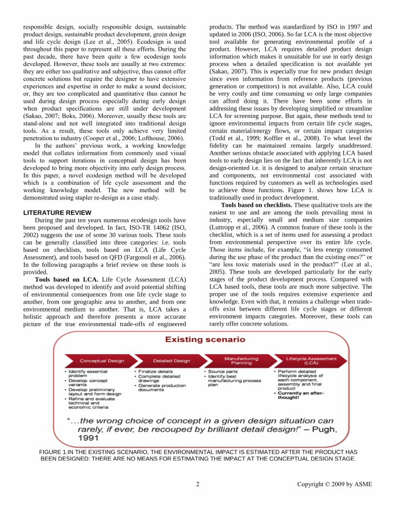
As pointed out by Pugh, “the wrong choice of concept in
a given design situation can rarely, if ever, be recouped by
brilliant detail design” (Pugh, 1991). This is also expected to
be the case for environmentally friendly design. Till now
design methods such as Quality Function Deployment (QFD),
functional component analysis, and Pugh chart have gained
prominence in the product design community as means to
develop better products. Unfortunately the decisions typically
rely on experience, intuition, or at best, on a few simplified
calculations (Iqbal et al., 2008). As a result, the choices made
or design concepts selected are viewed with skepticism and
are not free from biased and unsupported choices. The case is
even worse when environmental performance is considered as
a design factor since only very limited experience and
knowledge have been accumulated and usually a “life cycle”
perspective is missing (UNEP, 2005; Fargnoli et al., 2006).
Product design and development relating to improved
environmental performance has many expressions including
design for environment, ecological design, environmental
design, environmentally conscious design, environmentally
2 Copyright © 2009 by ASME
responsible design, socially responsible design, sustainable
product design, sustainable product development, green design
and life cycle design (Lee et al., 2005). Ecodesign is used
throughout this paper to represent all these efforts. During the
past decade, there have been quite a few ecodesign tools
developed. However, these tools are usually at two extremes:
they are either too qualitative and subjective, thus cannot offer
concrete solutions but require the designer to have extensive
experiences and expertise in order to make a sound decision;
or, they are too complicated and quantitative thus cannot be
used during design process especially during early design
when product specifications are still under development
(Sakao, 2007; Boks, 2006). Moreover, usually these tools are
stand-alone and not well integrated into traditional design
tools. As a result, these tools only achieve very limited
penetration to industry (Cooper et al., 2006; Lofthouse, 2006).
In the authors’ previous work, a working knowledge
model that collates information from commonly used visual
tools to support iterations in conceptual design has been
developed to bring more objectivity into early design process.
In this paper, a novel ecodesign method will be developed
which is a combination of life cycle assessment and the
working knowledge model. The new method will be
demonstrated using stapler re-design as a case study.
LITERATURE REVIEW During the past ten years numerous ecodesign tools have
been proposed and developed. In fact, ISO-TR 14062 (ISO,
2002) suggests the use of some 30 various tools. These tools
can be generally classified into three categories: i.e. tools
based on checklists, tools based on LCA (Life Cycle
Assessment), and tools based on QFD (Fargonoli et al., 2006).
In the following paragraphs a brief review on these tools is
provided.
Tools based on LCA. Life Cycle Assessment (LCA)
method was developed to identify and avoid potential shifting
of environmental consequences from one life cycle stage to
another, from one geographic area to another, and from one
environmental medium to another. That is, LCA takes a
holistic approach and therefore presents a more accurate
picture of the true environmental trade-offs of engineered
products. The method was standardized by ISO in 1997 and
updated in 2006 (ISO, 2006). So far LCA is the most objective
tool available for generating environmental profile of a
product. However, LCA requires detailed product design
information which makes it unsuitable for use in early design
process when a detailed specification is not available yet
(Sakao, 2007). This is especially true for new product design
since even information from reference products (previous
generation or competitors) is not available. Also, LCA could
be very costly and time consuming so only large companies
can afford doing it. There have been some efforts in
addressing these issues by developing simplified or streamline
LCA for screening purpose. But again, these methods tend to
ignore environmental impacts from certain life cycle stages,
certain material/energy flows, or certain impact categories
(Todd et al., 1999; Koffler et al., 2008). To what level the
fidelity can be maintained remains largely unaddressed.
Another serious obstacle associated with applying LCA based
tools to early design lies on the fact that inherently LCA is not
design-oriented i.e. it is designed to analyze certain structure
and components, not environmental cost associated with
functions required by customers as well as technologies used
to achieve those functions. Figure 1. shows how LCA is
traditionally used in product development.
Tools based on checklists. These qualitative tools are the
easiest to use and are among the tools prevailing most in
industry, especially small and medium size companies
(Luttropp et al., 2006). A common feature of these tools is the
checklist, which is a set of items used for assessing a product
from environmental perspective over its entire life cycle.
Those items include, for example, “is less energy consumed
during the use phase of the product than the existing ones?” or
“are less toxic materials used in the product?” (Lee at al.,
2005). These tools are developed particularly for the early
stages of the product development process. Compared with
LCA based tools, these tools are much more subjective. The
proper use of the tools requires extensive experience and
knowledge. Even with that, it remains a challenge when trade-
offs exist between different life cycle stages or different
environment impacts categories. Moreover, these tools can
rarely offer concrete solutions.
FIGURE 1.IN THE EXISTING SCENARIO, THE ENVIRONMENTAL IMPACT IS ESTIMATED AFTER THE PRODUCT HAS BEEN DESIGNED; THERE ARE NO MEANS FOR ESTIMATING THE IMPACT AT THE CONCEPTUAL DESIGN STAGE.

3 Copyright © 2009 by ASME
Tools based on QFD. The objective of a traditional QFD
is to convert customers‟ needs into engineering characteristics
and at the same time improve the quality level of the product.
By introducing environmental impacts of the product itself
and over its life cycle into QFDs as new customer needs, a set
of ecodesign tools have been developed. These include
Quality Function Deployment for the Environment, Green
Quality Function Deployment, and House of Ecology (Masui
et al., 2003; Sakao, 2007). In general, application of these
tools starts from collecting both customer needs and
environmental needs, and developing correlations between
these needs and quality characteristics. A functional analysis is
then performed to identify how quality characteristics are
correlated with engineering characteristics (including structure
or components) and hot spots from both environmental as well
as traditional qualities point of views. It can be observed that
QFD based tools are significantly different from LCA based
tools since the focus here is on the product specification
development stage. One serious drawback of these QFD based
tools (similar to traditional QFD) is that the development of
correlations between environmental needs and quality &
engineering characteristics is totally on designers, and usually
the correlations developed are based on knowledge from
traditional environmental engineering discipline without the
consideration of life cycle.
In summary, QFD based tools are more suitable for the
early product development phase when specifications are
being established and concepts are being generated. However,
without support from LCA, QFD based tools may lead to
biased identification of design targets. So naturally one may
argue a combined QFD/LCA tool may be more promising.
Actually this has been the focus of recent efforts on
developing ecodesign tools (Sakao, 2007). But still, there are
critical missing links in the above stated approach, which
leaves the inherent drawback of QFD left unaddressed, i.e.,
although LCA results are used to develop voices of
environment and weighting, they are not used to develop
correlations between environmental needs and quality &
engineering characteristics.
In the authors‟ previous work (Devanathan et al., 2009), a
methodology suitable for early design has been developed
which supports manual reasoning by mapping the elements of
the visual tools to the working knowledge model (WKM) (see
Figures 2 & 3). Another key aspect of the WKM is the ability
to handle multiple descriptions and alternatives of the
DesignModel, encountered in the initial stages of the design
process. The supported visual tools include: function-means
trees, function flow diagrams, function-component matrices,
SysML Requirements diagram, and the House of Quality.
WKM serves as a repository for all the information
encountered in early design namely, (1) the structure and
behavior representations of competing products, (2) the
FIGURE 2. WORKING KNOWLEDGE MODEL (WKM) PROVIDES A FRAMEWORK FOR STRUCTURING AND ACCESSING INFORMATION USED IN EARLY DESIGN THROUGH MEANS OF VISUAL TOOLS
Visual Tools
QFD F/M Tree
CAD SysML
C&CM …
Working Knowledge Model
Designer(s)
Acquisition
Access & Display
Structure
Sub-structure
Behavior
Sub-Behavior Artifact
Function
Sub-Functions
Attributes
ConstraintsConstraintsConstraints
DesignModel
Objectives
Requirements
Working Knowledge
A B
Different levels of fidelity
A depends on B
Different alternatives
FIGURE 3. PRODUCT INFORMATION ENTITIES THAT ARE CONSIDERED WITHIN THE WORKING KNOWLEDGE MODEL

4 Copyright © 2009 by ASME
alternative design concepts, and (3) the various refinements of
the function, structure and behavior descriptions of the current
design solution. This methodology was applied successfully to
capture a significant portion of the working knowledge during
the design of a Humanoid Robot in collaboration with the
Institute for Product Development IPEK, at University of
Karlsruhe, Germany. Figure 4 illustrates how the elements of
the WKM can be used to describe the content of specific
visual tools. One of the salient aspects of being able to model
the information content of visual tools is that, the visual tools
can be chained to maintain consistency among these tools
during the several iterations that occur in early design and also
eliminate the need to manually enter the same information
several times for different tools. Evidently, the working
knowledge model provides a way to address the missing link
in the QFD based ecodesign approach.
METHOD DEVELOPMENT The novel ecodesign methodology proposed here is a
seamless integration of life cycle assessment and working
knowledge model based visual tools. To make approach clear,
we use design of staplers as a didactic example (See Figure 5
for the overall approach). Most of these staplers available in
the market today consist of a magazine to hold staples, an
extruder to push a staple through a pile of papers, a bottom
plate to crimp the ends of the staple pin, and a housing to hold
all the parts together. These staplers are made of different
material such as plastics and metal. We would first like to
estimate the contribution of each function performed by the
stapler in addressing the user requirements. In this study, three
representative staplers on market are selected as benchmarks
i.e. an all metal one, a plastic one, and a compact one. It is also
assumed that all staplers have a service life of five years and
staple 5000 documents during life time. It can be observed that
(1) any new design is a novel combination of existing
concepts, and (2) product tear-down and benchmarking are an
essential part of any design process (Otto and Wood, 1999).
During the tear-down, designers identify the structure and
functions of competing products. Table 1 lists the bill of
materials for one of the benchmark staplers. Eco-analysis such
as LCA can be performed for a given product structure and
scores can be provided for the environmental impacts. Here
the environmental impacts considered are limited to global
warming in terms of carbon dioxide equivalent but other
impact categories can be also considered if desired. Figure 6
shows the LCA process tree and global warming potential
contribution based on product tear-down and bill of materials
as listed in Table 1. An interesting fact observed is that for
staplers the use phase dominates the life cycle environmental
impacts. For the stapler analyzed, a jam rate of 20% is
assumed. This suggests that a jam-free stapler may have better
environmental performance if this is achieved without
significantly increasing the environmental impacts associated
with the stapler itself. Moreover, LCA results of other staplers
suggest that the stapler made of mainly plastics is superior
when compared with the one made of metal from
environmental perspective.
Now, the challenge lies on how to interpolate the impact
of existing products so they can be used towards the new
design. This is indeed possible because, (1) products are
designed to perform certain function, (2) the products achieve
the functionality by means of their structure and behavior
(use) (Gero, 1990), and (3) the environmental impact is
computed using the structure and usage information.
Therefore there exists a theoretical pathway to connect
functional information to the environmental impact data
through the structure of existing product. It is therefore,
possible to estimate the environmental impact of each
function, albeit for existing products. Extrapolating the impact
for the functions of the current design provides a means to (1)
rank the functions in terms of their environmental impact, and
(2) estimate a baseline impact that the new design should
improve.
TABLE 1. BILL OF MATERIALS FOR A STAPLER
Item Name Qty. Material
Predominant m/f
process Weight (g)
1 Top housing 1 Plastic Injection molding 20.5
2 Bottom housing 1 Steel Stamping 30.1
3 Magazine indexer 1 Copper Blanking 1.3
4 Magazine guide 1 Steel Stamping 8.1
5 Magazine spring 1 Spring SteelExtrusion 1.2
6 Impact plate 1 Steel Blanking 3.6
7 Extruder 1 Steel Blanking 1.4
Requ
irem
ents
Direction
Targets Customer
Requirements
Engineering Characteristics
Co-relation
Artifact
Attribute
Objective
Function
Requirement
Constraint
Qualitative
Co-relation Matrix
Require me nts
Targets
Eng. Characteristics
Direction
(a) House of Quality
Relationship Matrix
Components Component
Fun
ctio
n
Function-
Component Matrix
(b) Elements of the Working Knowledge Model (c) Function-Component Matrix
FIGURE 4. DESCRIPTION OF THE HOUSE OF QUALITY AND FUNCTION-COMPONENT MATRIX USING WKM ELEMENTS (DEVANATHAN ET AL., 2009)

5 Copyright © 2009 by ASME
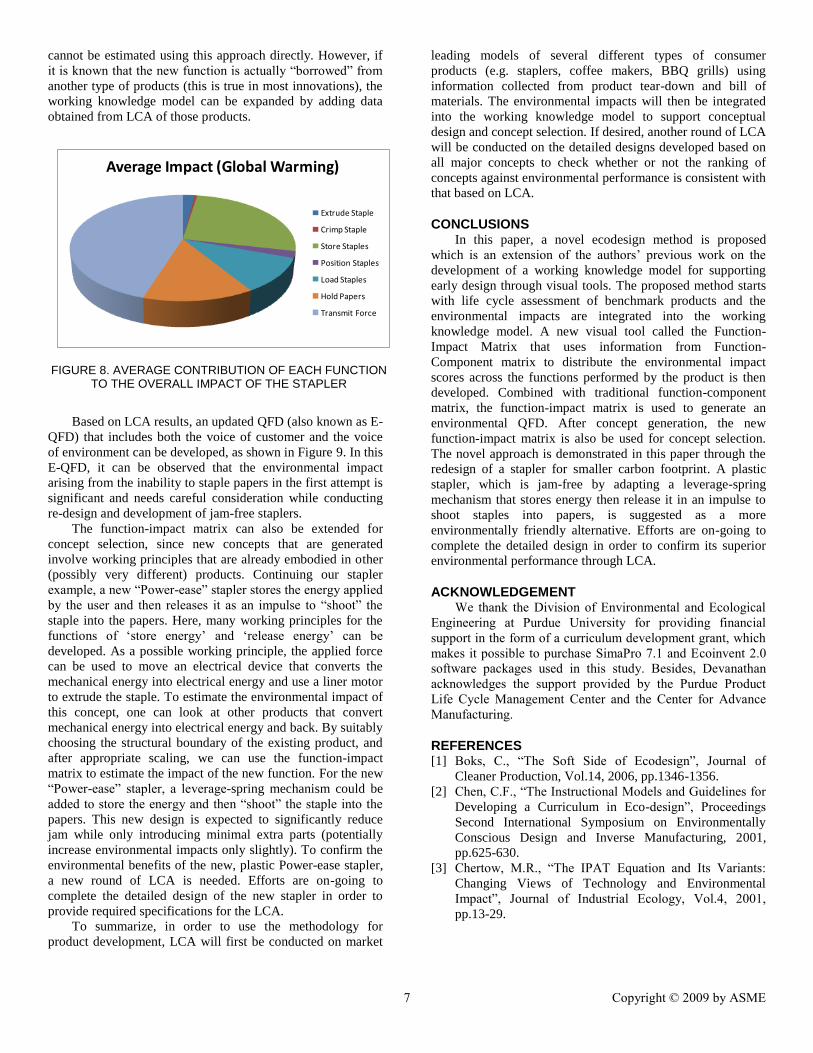
Here a new visual tool called the Function-Impact Matrix that
uses information from Function-Component matrix to
distribute the environmental impact scores across the functions
performed by the product (stapler) is proposed. An example of
the function-impact matrix is shown in Figure 6. Similar
analysis can be performed for all the competing staplers and
an average impact of particular function can be obtained.
Although the actual impact of the particular function for a new
stapler will differ from this value, it nevertheless provides a
baseline needed for decision making. The main aspect of the
function-impact matrix is to identify which functions are
important and which functions need to be re-examined to
obtain a better design. The function-impact matrix is drawn
for all the competing staplers and the average impact of each
function is depicted in Figure 8. From this figure, it is clear the
function “transmit force” accounts for 40% of the total impact
of the stapler. It should be noted that the impact of any new
function that is not performed by existing competing product
Pe
rce
nt
Imp
act
Pe
rce
nt
Imp
act
Pe
rce
nt
Imp
act
Pe
rce
nt
Imp
act
Pe
rce
nt
Imp
act
Pe
rce
nt
Imp
act
Pe
rce
nt
Imp
act
30 0.223 20 0.1486 50 0.3716 0.7432
30 0.1372 50 0.2287 0.4574
5 0.011 65 0.1435 10 0.0221 10 0.0221 10 0.0221 0.2207
100 0.0531
70 0.019 30 0.0081 0.0271
100 0.0561 0.0561
0.03 0.0081 0.3664 0.0221 0.1707 0.1593 0.6564 1.5576
Function - Impact Matrix
Extr
ud
e S
tap
le
Cri
mp
Sta
ple
Pins
Magazine
Impact Plate
Extruder
Total
Top Housing
Bottom Housing
Sto
re S
tap
les
Po
siti
on
Sta
ple
s
Load
Sta
ple
s
Ho
ld P
ape
rs
Tran
smit
Fo
rce
En
viro
nm
en
tal I
mp
act
(Glo
bal
War
min
g)
Function
Component
FIGURE 6. FUNCTION-IMPACT MATRIX FOR ESTIMATING THE IMPACT OF INDIVIDUAL FUNCTIONS THROUGH MEANS OF THE STRUCTURE INFORMATION
FIGURE 5. OVERVIEW OF THE APPROACH THAT INTEGRATES LIFE CYCLE ASSESSMENT AND VISUAL TOOLS FOR THE STAPLER EXAMPLE

6 Copyright © 2009 by ASME
Sta
ple
r
FIG
UR
E 7
. L
IFE
CY
CLE
GLO
BA
L W
AR
MIN
G P
OT
EN
TIA
L O
F T
HE
CO
MP
AC
T S
TA
PL
ER
CA
LC
UL
AT
ED
US
ING
SIM
AP
RO
7.1
/EC
OIN
VE
NT
2.0
7 Copyright © 2009 by ASME
cannot be estimated using this approach directly. However, if
it is known that the new function is actually “borrowed” from
another type of products (this is true in most innovations), the
working knowledge model can be expanded by adding data
obtained from LCA of those products.
Based on LCA results, an updated QFD (also known as E-
QFD) that includes both the voice of customer and the voice
of environment can be developed, as shown in Figure 9. In this
E-QFD, it can be observed that the environmental impact
arising from the inability to staple papers in the first attempt is
significant and needs careful consideration while conducting
re-design and development of jam-free staplers.
The function-impact matrix can also be extended for
concept selection, since new concepts that are generated
involve working principles that are already embodied in other
(possibly very different) products. Continuing our stapler
example, a new “Power-ease” stapler stores the energy applied
by the user and then releases it as an impulse to “shoot” the
staple into the papers. Here, many working principles for the
functions of „store energy‟ and „release energy‟ can be
developed. As a possible working principle, the applied force
can be used to move an electrical device that converts the
mechanical energy into electrical energy and use a liner motor
to extrude the staple. To estimate the environmental impact of
this concept, one can look at other products that convert
mechanical energy into electrical energy and back. By suitably
choosing the structural boundary of the existing product, and
after appropriate scaling, we can use the function-impact
matrix to estimate the impact of the new function. For the new
“Power-ease” stapler, a leverage-spring mechanism could be
added to store the energy and then “shoot” the staple into the
papers. This new design is expected to significantly reduce
jam while only introducing minimal extra parts (potentially
increase environmental impacts only slightly). To confirm the
environmental benefits of the new, plastic Power-ease stapler,
a new round of LCA is needed. Efforts are on-going to
complete the detailed design of the new stapler in order to
provide required specifications for the LCA.
To summarize, in order to use the methodology for
product development, LCA will first be conducted on market
leading models of several different types of consumer
products (e.g. staplers, coffee makers, BBQ grills) using
information collected from product tear-down and bill of
materials. The environmental impacts will then be integrated
into the working knowledge model to support conceptual
design and concept selection. If desired, another round of LCA
will be conducted on the detailed designs developed based on
all major concepts to check whether or not the ranking of
concepts against environmental performance is consistent with
that based on LCA.
CONCLUSIONS In this paper, a novel ecodesign method is proposed
which is an extension of the authors‟ previous work on the
development of a working knowledge model for supporting
early design through visual tools. The proposed method starts
with life cycle assessment of benchmark products and the
environmental impacts are integrated into the working
knowledge model. A new visual tool called the Function-
Impact Matrix that uses information from Function-
Component matrix to distribute the environmental impact
scores across the functions performed by the product is then
developed. Combined with traditional function-component
matrix, the function-impact matrix is used to generate an
environmental QFD. After concept generation, the new
function-impact matrix is also be used for concept selection.
The novel approach is demonstrated in this paper through the
redesign of a stapler for smaller carbon footprint. A plastic
stapler, which is jam-free by adapting a leverage-spring
mechanism that stores energy then release it in an impulse to
shoot staples into papers, is suggested as a more
environmentally friendly alternative. Efforts are on-going to
complete the detailed design in order to confirm its superior
environmental performance through LCA.
ACKNOWLEDGEMENT We thank the Division of Environmental and Ecological
Engineering at Purdue University for providing financial
support in the form of a curriculum development grant, which
makes it possible to purchase SimaPro 7.1 and Ecoinvent 2.0
software packages used in this study. Besides, Devanathan
acknowledges the support provided by the Purdue Product
Life Cycle Management Center and the Center for Advance
Manufacturing.
REFERENCES [1] Boks, C., “The Soft Side of Ecodesign”, Journal of
Cleaner Production, Vol.14, 2006, pp.1346-1356.
[2] Chen, C.F., “The Instructional Models and Guidelines for
Developing a Curriculum in Eco-design”, Proceedings
Second International Symposium on Environmentally
Conscious Design and Inverse Manufacturing, 2001,
pp.625-630.
[3] Chertow, M.R., “The IPAT Equation and Its Variants:
Changing Views of Technology and Environmental
Impact”, Journal of Industrial Ecology, Vol.4, 2001,
pp.13-29.
Average Impact (Global Warming)
Extrude Staple
Crimp Staple
Store Staples
Position Staples
Load Staples
Hold Papers
Transmit Force
FIGURE 8. AVERAGE CONTRIBUTION OF EACH FUNCTION TO THE OVERALL IMPACT OF THE STAPLER

8 Copyright © 2009 by ASME
FIG
UR
E 9
. E
-QF
D I
NC
LU
DE
S B
OT
H V
OIC
E O
F C
US
TO
ME
RS
AN
D V
OIC
E O
F E
NV
IRO
NM
EN
T

9 Copyright © 2009 by ASME
[4] Cooper, J.S., Fava, J.A.,” Life-Cycle Assessment
Practitioner Survey: Summary of Results”, Journal of
Industrial Ecology, Vol.10, 2006, pp.12-14.
[5] Curran, M.A., “Life Cycle Assessment: Principles And
Practice”, EPA/600/R-06/060, 2006.
[6] Devanathan, S., Sauter, C., Albers, A., Ramani, K., “A
working knowledge model for supporting early design
through visual tools”, International Conference on
Engineering Design (ICED), 2009, Stanford, CA, USA
(accepted).
[7] Fargnoli, M., Kimura, F., “Sustainable Design of Modern
Industrial Products”, Proceedings of 13th
CIRP
International Conference on Life Cycle Engineering,
2006, pp.189-194.
[8] Gero J.S., “Design Prototypes: A Knowledge
Representation Schema for Design”, AI Magazine, Vol.
11(4), 1990, pp. 26–36.
[9] Iqbal, L., Crossley, W., Weisshaar, T. and Sullivan, J.,
"Higher Level Design Methods Applied to the Conceptual
Design of an MALE UAV," AIAA-2008-5908, 12th
AIAA/ISSMO Multidisciplinary Analysis and
Optimization Conference, Victoria, BC, Sep. 10-12, 2008.
[10] ISO TR 14062: Environmental Management – Integrating
Environmental Aspects into Product Design and
Development, 2002.
[11] ISO 14040, Environmental Management -- Life Cycle
Assessment -- Principles and Framework, 2006.
[12] ISO 14044, Environmental Management -- Life Cycle
Assessment -- Requirements and Guidelines, 2006.
[13] Koffler, C., Krinke, S., Schebek, L., Buchgeister, J.,
“Volkswagen slimLCI: A Procedure for Streamlined
Inventory Modeling within Life Cycle Assessment of
Vehicles”, International Journal of Vehicle Design,
Vol.46, 2008, pp.172-188.
[14] Lee, K.M., Park, P.J., “EcoDesign: Best Practice of ISO-
14062”, Eco-product Research Institute(ERI), Ajou
University, Korea, 2005.
[15] Lofthouse, v., “Ecodesign Tools for Designer: Defining
the Requirements”, Journal of Cleaner Production,
Vol.14, 2006, pp.1386-1395.
[16] Luttropp, C., Lagerstedt, J., “EcoDesign and the Ten
Golden Rules: Generic Advice for Merging
Environmental Aspects into Product Development”,
Hournal of Cleaner Production, Vol.14, 2006, pp.1396-
1408.
[17] Masui, K., Sakao, T., Kobayashi, M., Inaba, A.,
“Applying Quality Function Deployment to
Environmentally Consious Design”, International Journal
of Quality and Reliability Management, Vol.20, 2003,
pp.90-106.
[18] Matthews, H.S., Environmental Life Cycle Assessment,
Course Materials, 2006,
http://www.ce.cmu.edu/~hsm/lca2006/, accessed March
1st, 2009.
[19] Mihelcic, J.R., Paterson, K.G., Phillips, L.D., Zhang, Q.,
Watkins, D.W., Barkdoll, B.D., Fuchs, V.J., Fry, L.M.,
Hokanson, D.R., “Educating Engineers in the Sustainable
Futures Model with a Global Perspective”, Civil
Engineering and Environmental Systems, Vol. 25, 2008 ,
pp. 255–263.
[20] National Academy of Engineering, “Grand Challenges for
Engineering”, 2008.
[21] Otto K.N., Wood, K.L., Product Design: Techniques in
Reverse Engineering and New Product Development,
Prentice Hall, 2001.
[22] Pugh, S., "Conceptual Design," in Total Design:
Integrated Methods for Successful Product Engineering,
Addison-Wesley, 1991, pp. 67-100.
[23] Pappas, E.C., Kander, R.G., “Sustainable engineering
design at James Madison University”, Proceedings -
Frontiers in Education Conference, 38th ASEE/IEEE
Frontiers in Education Conference, 2008, pp.T4C.14-
T4C.15.
[24] Sakao, T., “A QFD-centred Design Methodology for
Environmentally Conscious Product Design”,
International Journal of Production Research, Vol.45,
2007, pp.4143-4162.
[25] Todd, J.A., Curran, M.A., “Streamlined Life-Cycle
Assessment: A Final Report from the SETAC North
America Streamlined LCA Workgroup”, Society of
Environmental Toxicology and Chemistry (SETAC) and
SETAC Foundation for Environmental Education, 1999.
[26] UNEP, “Life Cycle Approaches: The Road from Analysis
to Practice”, A UNEP/ SETAC Life Cycle Initiative
Report, 2005.

10 Copyright © 2009 by ASME