Embed Size (px)
Citation preview
A Close Look at Research
and Innovations
IntegratingTNITechnologies
On the Occasion of the
10 th
Anniversaryof Thai-Nichi Institute
of Technology
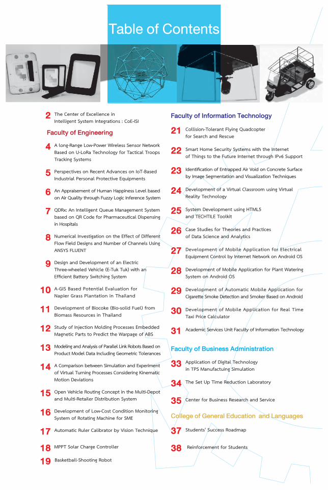
Table of Contents
2 The Center of Excellence inIntelligent System Integrations : CoE-ISI
Faculty of Engineering
4 A long-Range Low-Power Wireless Sensor NetworkBased on U-LoRa Technology for Tactical TroopsTracking Systems
5 Perspectives on Recent Advances on IoT-BasedIndustrial Personal Protective Equipments
6 An Appraisement of Human Happiness Level basedon Air Quality through Fuzzy Logic Inference System
7 QDRx: An Intelligent Queue Management Systembased on QR Code for Pharmaceutical Dispensingin Hospitals
8 Numerical Investigation on the Effect of DifferentFlow Field Designs and Number of Channels UsingANSYS FLUENT
9 Design and Development of an ElectricThree-wheeled Vehicle (E-Tuk Tuk) with anEfficient Battery Switching System
10 A-GIS Based Potential Evaluation forNapier Grass Plantation in Thailand
11 Development of Biocoke (Bio-solid Fuel) from Biomass Resources in Thailand
12 Study of Injection Molding Processes EmbeddedMagnetic Parts to Predict the Warpage of ABS
13 Modeling and Analysis of Parallel Link Robots Based onProduct Model Data Including Geometric Tolerances
14 A Comparison between Simulation and Experimentof Virtual Turning Processes Considering KinematicMotion Deviations
15 Open Vehicle Routing Concept in the Multi-Depotand Multi-Retailer Distribution System
16 Development of Low-Cost Condition MonitoringSystem of Rotating Machine for SME
17 Automatic Ruler Calibrator by Vision Technique
18 MPPT Solar Charge Controller
19 Basketball-Shooting Robot
21 Collision-Tolerant Flying Quadcopterfor Search and Rescue
22 Smart Home Security Systems with the Internetof Things to the Future Internet through IPv6 Support
23 Identification of Entrapped Air Void on Concrete Surfaceby Image Segmentation and Visualization Techniques
24 Development of a Virtual Classroom using VirtualReality Technology
25 System Development using HTML5and TECHTILE Toolkit
26 Case Studies for Theories and Practicesof Data Science and Analytics
27 Development of Mobile Application for ElectricalEquipment Control by Internet Network on Android OS
28 Development of Mobile Application for Plant WateringSystem on Android OS
29 Development of Automatic Mobile Application forCigarette Smoke Detection and Smoker Based on Android
30 Development of Mobile Application for Real TimeTaxi Price Calculator
31 Academic Services Unit Faculty of Information Technology
33 Application of Digital Technologyin TPS Manufactuing Simulation
34 The Set Up Time Reduction Laboratory
35 Center for Business Research and Service
College of General Education and Languages
37 Students' Success Roadmap
38 Reinforcement for Students
Faculty of Business Administration
Faculty of Information Technology
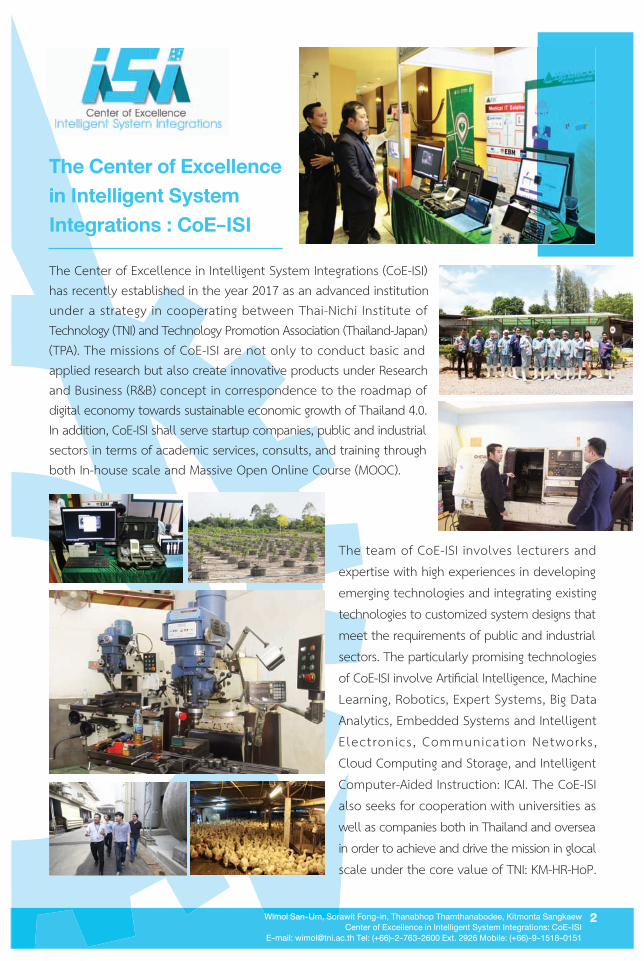
The Center of Excellence
in Intelligent System
Integrations : CoE-ISI
The team of CoE-ISI involves lecturers andexpertise with high experiences in developingemerging technologies and integrating existingtechnologies to customized system designs thatmeet the requirements of public and industrialsectors. The particularly promising technologiesof CoE-ISI involve Artificial Intelligence, MachineLearning, Robotics, Expert Systems, Big DataAnalytics, Embedded Systems and IntelligentElectronics, Communicat ion Networks,Cloud Computing and Storage, and IntelligentComputer-Aided Instruction: ICAI. The CoE-ISIalso seeks for cooperation with universities aswell as companies both in Thailand and overseain order to achieve and drive the mission in glocalscale under the core value of TNI: KM-HR-HoP.
The Center of Excellence in Intelligent System Integrations (CoE-ISI)has recently established in the year 2017 as an advanced institutionunder a strategy in cooperating between Thai-Nichi Institute ofTechnology (TNI) and Technology Promotion Association (Thailand-Japan)(TPA). The missions of CoE-ISI are not only to conduct basic andapplied research but also create innovative products under Researchand Business (R&B) concept in correspondence to the roadmap ofdigital economy towards sustainable economic growth of Thailand 4.0.In addition, CoE-ISI shall serve startup companies, public and industrialsectors in terms of academic services, consults, and training throughboth In-house scale and Massive Open Online Course (MOOC).
2Wimol San-Um, Sorawit Fong-in, Thanabhop Thamthanabodee, Kitmonta Sangkaew
Center of Excellence in Intelligent System Integrations: CoE-ISI
E-mail: [email protected] Tel: (+66)-2-763-2600 Ext. 2926 Mobile: (+66)-9-1518-0151

Faculty
of
Engineering
Abstract
Proposed Tactical Troops Tracking
System
Abstract
Proposed Tactical Troops Tracking
System
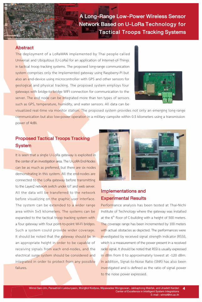
It is seen that a single U-LoRa gateway is exploited inthe center of an investigation area. The U-LoRA End-Nodescan be as much as preferred, but there are six nodesdemonstrating in this system. All the end-nodes are
connected to the LoRa gateway before transmittingto the Layer2 network switch under IoT and web server.All the data will be transferred to the networkbefore visualizing on the graphic user interface.
The system can be extended to a wider range
area within 5×5 kilometers. The systems can beexpanded to the tactical troop tracking system witha four gateway with four point-to-point Wi-Fi bridges.
Such a system could provide wider coverage.
It should be noted that the gateway should be in
an appropriate height in order to be capable of
receiving signals from each end-nodes, and theelectrical surge system should be considered and
integrated in order to protect from any possible
failures.
Implementations and
Experimental Results
Performance analysis has been tested at Thai-NichiInstitute of Technology where the gateway was installed
at the 6th floor of C-building with a height of 500 meters.The coverage range has been incremented by 100 meters
with actual obstacles as depicted. The performances were
investigated by received signal strength indicator (RSSI),which is a measurement of the power present in a received
radio signal. It should be noted that RSSI is usually expressedin dBm from 0 to approximately lowest at -120 dBm.In addition, Signal-to-Noise Ratio (SNR) has also beeninvestigated and is defined as the ratio of signal powerto the noise power expressed.
Wimol San-Um, Pansathorn Lekbunyasin, Mongkol Kodyoo, Wipawadee Wongsuwan, Jakkaphong Makfak, and Jiradett Kerdsri
Center of Excellence in Intelligent System Integrations
E-mail : [email protected]
The deployment of a LoRaWAN implemented by Thai people calledUniversal and Ubiquitous (U-LoRa) for an application of Internet-of-Thingsin tactical troop tracking systems. The proposed long-range communicationsystem comprises only the implemented gateway using Raspberry-Pi butalso an end-device using microcontroller with GPS and other sensors forgeological and physical tracking. The proposed system employs fourgateways with bridge-to-bridge WIFI connection for communication to the
server. The end node can be integrated more than ten types of sensors
such as GPS, temperature, humidity, and water sensors. All data can bevisualized real-time via monitor station. The proposed system provides not only an emerging long-range
communication but also low-power operation in a military campsite within 0.5 kilometers using a transmissionpower of 4dBi.
4
A Long-Range Low-Power Wireless Sensor
Network Based on U-LoRa Technology for
Tactical Troops Tracking Systems
Prat Khajai and Wimol San-Um
Center of Excellence in Intelligent System Integrations
E-mail : [email protected]
Commercially Avaliable Start PPEs
Conclusion
A Future Work on The Procosed Smart
PPEs Platform
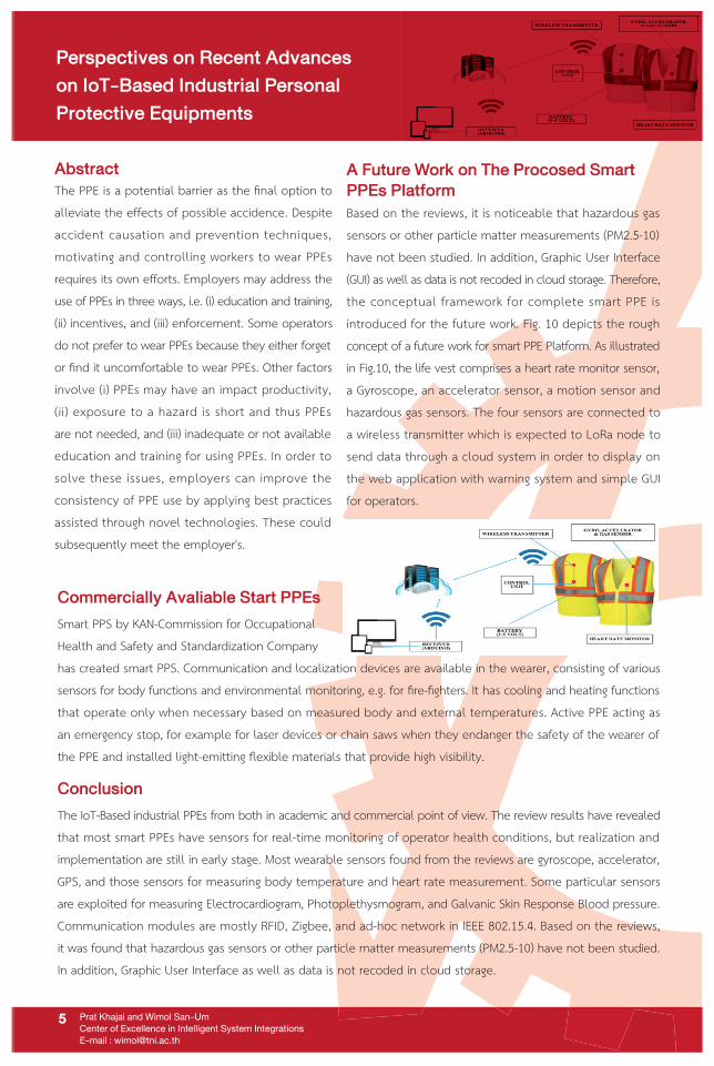
Based on the reviews, it is noticeable that hazardous gassensors or other particle matter measurements (PM2.5-10)have not been studied. In addition, Graphic User Interface(GUI) as well as data is not recoded in cloud storage. Therefore,the conceptual framework for complete smart PPE isintroduced for the future work. Fig. 10 depicts the roughconcept of a future work for smart PPE Platform. As illustratedin Fig.10, the life vest comprises a heart rate monitor sensor,a Gyroscope, an accelerator sensor, a motion sensor andhazardous gas sensors. The four sensors are connected to
a wireless transmitter which is expected to LoRa node tosend data through a cloud system in order to display on
the web application with warning system and simple GUI
for operators.
Perspectives on Recent Advances
on IoT-Based Industrial Personal
Protective Equipments
5
Abstract
The PPE is a potential barrier as the final option toalleviate the effects of possible accidence. Despiteaccident causation and prevention techniques,motivating and controlling workers to wear PPEsrequires its own efforts. Employers may address the
use of PPEs in three ways, i.e. (i) education and training,(ii) incentives, and (iii) enforcement. Some operatorsdo not prefer to wear PPEs because they either forgetor find it uncomfortable to wear PPEs. Other factorsinvolve (i) PPEs may have an impact productivity,(ii) exposure to a hazard is short and thus PPEsare not needed, and (iii) inadequate or not availableeducation and training for using PPEs. In order tosolve these issues, employers can improve theconsistency of PPE use by applying best practicesassisted through novel technologies. These could
subsequently meet the employer's.
Smart PPS by KAN-Commission for OccupationalHealth and Safety and Standardization Company
has created smart PPS. Communication and localization devices are available in the wearer, consisting of varioussensors for body functions and environmental monitoring, e.g. for fire-fighters. It has cooling and heating functionsthat operate only when necessary based on measured body and external temperatures. Active PPE acting asan emergency stop, for example for laser devices or chain saws when they endanger the safety of the wearer ofthe PPE and installed light-emitting flexible materials that provide high visibility.
The IoT-Based industrial PPEs from both in academic and commercial point of view. The review results have revealedthat most smart PPEs have sensors for real-time monitoring of operator health conditions, but realization andimplementation are still in early stage. Most wearable sensors found from the reviews are gyroscope, accelerator,GPS, and those sensors for measuring body temperature and heart rate measurement. Some particular sensorsare exploited for measuring Electrocardiogram, Photoplethysmogram, and Galvanic Skin Response Blood pressure.Communication modules are mostly RFID, Zigbee, and ad-hoc network in IEEE 802.15.4. Based on the reviews,it was found that hazardous gas sensors or other particle matter measurements (PM2.5-10) have not been studied.In addition, Graphic User Interface as well as data is not recoded in cloud storage.

Research BackgroundsResearch BackgroundsAn appraisement of Human Happiness Level (HHL) based on Air Quality (AQ) through the use of Fuzzy LogicInference System (FIS) system. Such a FIS has recently been realized as a potential alternative to that of
conventional AQ assessment based on standard scales, which encounter practical difficulties on complicatedmeasures of various hazardous attributes and levels of chemical compounds in air. Despite the fact that severalfuzzy-based AQ models have been reported, no fully-developed AQ model that considers from physical attributesto human actualization, especially happiness, has been reported. In this paper, five parameters affecting onhuman health, involving PM2.5, CO, temperature, humidity, and air pressure, have been considered as inputsfor the proposed fuzzy-based AQ model.
Conclusion
Nattaphon Talmongkol, Noppadon Pongpisuttinun, and Wimol San-Um
Center of Excellence in Intelligent System Integrations
E-mail : [email protected]
This Topic has presented The simulation results were
performed using MATLAB Toolbox 2016a. The particularset of 109 rules was employed with OR and AND operators.Trapezoidal member ship function was realized for
temperature, relative humidity, and air pressure. On theother hand, Gaussian membership function was realizedfor PM2.5 and CO. A Centroid method was realizedin Defuzzification stage. This paper has six human happinesslevels have been suggested, involving happy, comfort, unhappy, depress, sad, and feel sick. This paper hascompletely demonstrated membership plots, the 3-dimentional view of HLL between particulate matter versusCarbon monoxide, and the 3-dimentional view of HLL between temperatures versus relative humidity.The circuit board has been developed based on Arduino with various sensors, including HTS221, PMS1003,MiCS-6814, BMP280, ESP8266, and a power supply module. Implementation on FIS on Android application is beingdeveloped for further use in real-world applications. It has been proven that FIS is useful to evaluate an air
quality and appraise human happiness level, leading to healthy and happy livings of human kinds.
6
Simulation Result
Simulations have been performed using MATLABdemonstrates some examples the linguistic rules versus
linguistic variables, indicating all six levels of HHL.Rule composition was performed and the fuzzy.
An Appraisement of Human Happiness Level based
on Air Quality through Fuzzy Logic Inference System
Abstract
Chanopas Vongpiboon and Wimol San-um
Center of Excellence in Intelligent System Integrations
E-mail : [email protected]
Conclusion
An Intelligent Queue Management System based onQR Code for Pharmaceutical Dispensing in Hospitals (QDRx)is an application that allows patients to be comfortable
and the satisfaction of the patients because the smartphone
is close to the patients. It’s allow patients to get fast
information by communicating over the Internet.
By applying QR code to contain data and using MQTTprotocol for data transmission over the Internet to develop
applications. Expected to be available in the hospital.
Methodology
The pharmaceutical dispensing of hospitals will be
different from the restaurant queue system or other
queue system. There are two types of queues: normal
queues and urgent queues. Because some patients haveto take the medication on time or the patient must takethe medication immediately after a medical examination.
The proposed queue system consists of three parts
including, smartphone applications, queue generationand queue calling. After the patients have seen the
doctor successfully. The patients have to receive the
queue from the hospital services by using their mobile
application on smartphone called "QDRx" to receive queuesthrough the queue generator. When registering a queue
via the application then they can view their own queue
and number of waiting queue through the application
As a result, the patients can do their own personal activitiesand freedom to go anywhere else while waiting in line.
The notification will alerts to the patient previous queuehas left 5 queues. For patients without a smartphone.
The system can print a queue card. They have to sit
and wai t unt i l cal l a round hospi ta l serv ice .
The notification will be alert by sound or LCD screen.
Due to the problem of pharmaceutical dispensing inhospital and potential of smartphone above. This
research offer an Intelligent Queue Management Systembased on QR Code for Pharmaceutical Dispensing inHospitals v ia appl icat ion div ided in 2 parts .1. Smartphone application for scan QR code to receivequeue. Patients will be able to view the queue detailsand will be alerted after near queue. During the waitingperiod, the patients can do other activities and willincrease the satisfaction of patients in the hospital.
2. Application for call queue and generate queue for
pharmacists.
Results
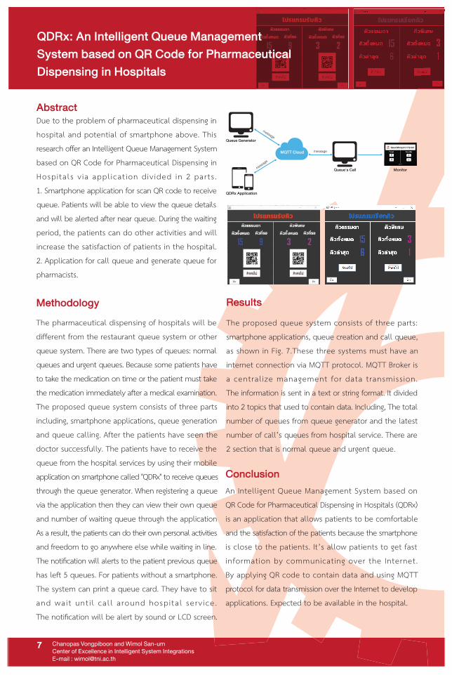
The proposed queue system consists of three parts:
smartphone applications, queue creation and call queue,as shown in Fig. 7.These three systems must have an
internet connection via MQTT protocol. MQTT Broker isa central ize management for data transmission.
The information is sent in a text or string format. It divided
into 2 topics that used to contain data. Including, The totalnumber of queues from queue generator and the latest
number of call’s queues from hospital service. There are
2 section that is normal queue and urgent queue.
7
Queue Generator
QDRx Application
Queue's Call Monitor
MQTT Cloud message
message
message
QDRx: An Intelligent Queue Management
System based on QR Code for Pharmaceutical
Dispensing in Hospitals
Introduction Model DevelopmentIntroduction Model Development
Results & Discussion
In Fig. 3, numerical results showed a good agreementwith experimental data. The IV performance curve of thedifferent flow fields is displayed in Fig. 4. The results revealedthat the 1S flow field provided the best performance,while the worst was found in the parallel. Although the1S flow field was also found the best in eliminating theliquid water, as seen in Fig. 5, the pressure drop (see Fig. 6)was found extraordinary high as compared to that of theothers. Therefore, the 1S flow field was not appropriate tobe used in a commercial scale since it requires a power tocompensate the pressure drop.
The number of channels affects the small-size PEFCperformance greater than the flow field designs since as thenumber of channels increases, the less amount of watersaturation, higher performance and pressure drop werefound. However, the influence of designs will be greater as thenumber of channels increases. With the same number ofchannels, the PIS flow fields performed better than theS flow fields as their geometry provided higher reactantflow velocity (see Fig. 7). Hence, the PIS flow fields were morepreferable than the S flow fields since a flow field with a highnumber of channels is required in a commercial scale fora lower pressure drop.
One of the key components of a polymer electrolytefuel cell (PEFC) is the reactant flow field and its bipolarplate since they perform several functions affectingPEFC performance, such as keeping the reactantsseparate from each other, distributing them to thecatalyst layer, distributing the electrons to the externalcircuit and also helping of water management.
An improper designed flow field of a polymer electrolytefuel cell (PEFC) can cause the maldistributions, resultingin the reduction of PEFC performance and lifetime.Although there are several researches investigatingthe effect of flow field design, the parallel in series flowfields, which are the commercial flow fields sold byElectrochem Inc., however, have received a very lowattention.Thus, the in-depth investigation of the parallelin series flow field has not yet been carried out.
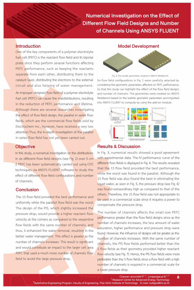
Fig. 2 The model geometries created in ANSYS Workbench
8
Six flow field configurations in Fig. 1 were carefully selected byconsidering the geometric parameters affected on PEFC performance.So that this study can highlight the effect of the flow field designsand number of channels. The geometries were created on ANSYSWorkbench based on the realistic geometric parameters and importedinto ANSYS FLUENT to compute by using the add-on module.
Conclusion
The 1S flow field provided the best performance anduniformity while the parallel flow field was the worst.The design of the PIS, which slightly increased thepressure drop, would provide a higher reactant flowvelocity at the corners as compared to the serpentineflow fields with the same number of channels, andthus, it enhanced the water removal, resulting in thebetter water management. This effect is greater as thenumber of channels increases. This result is significantand would contribute an impact to the larger cell areaPEFC that used a much more number of channels flowfield to avoid the large pressure drop.
Objective
In this study, a numerical investigation on the distributionsin six different flow field designs (see Fig. 1) over 5 cm2 PEFC has been systematically carried out using CFDtechniques via ANSYS FLUENT software to study theeffect of different flow field configurations and numberof channels.
Numerical Investigation on the Effect of
Different Flow Field Designs and Number
of Channels Using ANSYS FLUENT
Charoen-amornkitt P. , Limjeerajarus N.
¹ Research Center for Advanced Energy Technology
Automotive Engineering Program, Faculty of Engineering, Thai-Nichi Institute of Technology E-mail: [email protected]
1, 2 1, 2 *
2
IntroductionA Three-wheeled vehicle so-called Tuk Tuk is one of Thailand’s cultural identities. The conventional Tuk Tuk usesinternal combustion engines (ICES) and releases greenhouse gases which causes the global warming. Replacing theconventional engine with an electric motor can be a promising solution to keep operating Tuk Tuk for Thai’s tourismand also reducing the pollutions. However, a major technological barrier which prevents the electric Tuk Tuk(E-Tuk Tuk) from the global commercial market is its too long recharging time, as compared with the gas refill timeof the conventional Tuk Tuk. Thus, instead of recharging it, switching the battery at a service station can be a goodanswer solving such problem.
Nuttapol Limjeerajarus, Naren Chaithanee and RCAET Research Team
Automotive Engineering Program, Research Center for Advanced Energy Technology, Faculty of Engineering, Thai-Nichi Institute of Technology
E-mail: [email protected]
Research Methodology
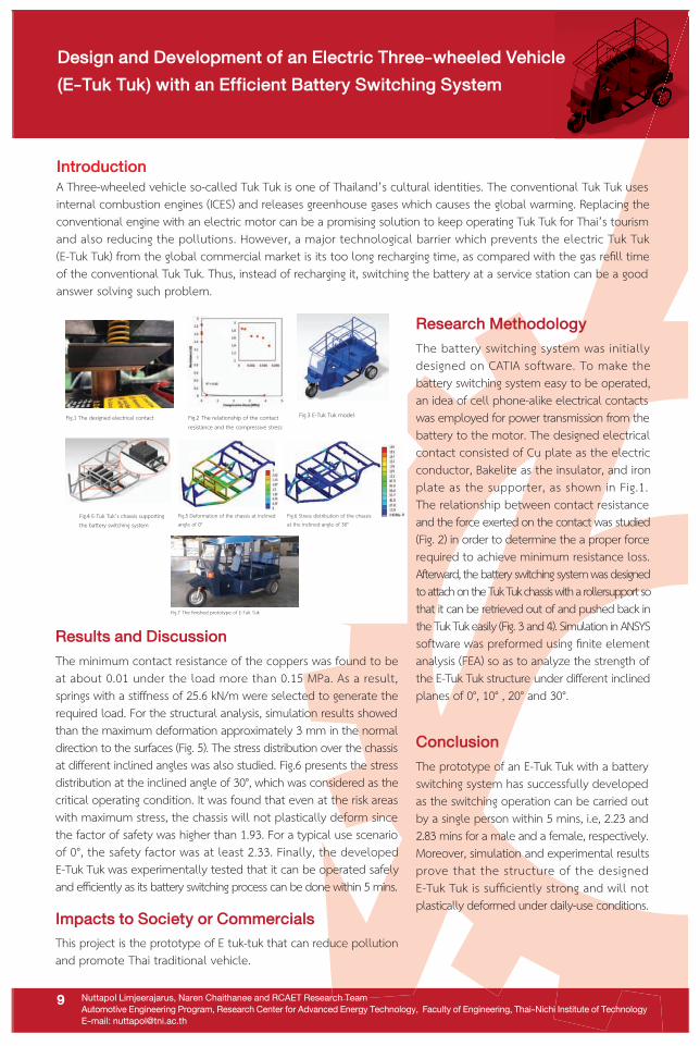
The battery switching system was initiallydesigned on CATIA software. To make thebattery switching system easy to be operated,an idea of cell phone-alike electrical contactswas employed for power transmission from thebattery to the motor. The designed electricalcontact consisted of Cu plate as the electricconductor, Bakelite as the insulator, and ironplate as the supporter, as shown in Fig.1.The relationship between contact resistanceand the force exerted on the contact was studied(Fig. 2) in order to determine the a proper forcerequired to achieve minimum resistance loss.Afterward, the battery switching system was designedto attach on the Tuk Tuk chassis with a rollersupport sothat it can be retrieved out of and pushed back inthe Tuk Tuk easily (Fig. 3 and 4). Simulation in ANSYSsoftware was preformed using finite elementanalysis (FEA) so as to analyze the strength ofthe E-Tuk Tuk structure under different inclinedplanes of 0°, 10° , 20° and 30°.
Conclusion
The prototype of an E-Tuk Tuk with a batteryswitching system has successfully developedas the switching operation can be carried outby a single person within 5 mins, i.e, 2.23 and2.83 mins for a male and a female, respectively.Moreover, simulation and experimental resultsprove that the structure of the designedE-Tuk Tuk is sufficiently strong and will notplastically deformed under daily-use conditions.
Results and Discussion
The minimum contact resistance of the coppers was found to beat about 0.01 under the load more than 0.15 MPa. As a result,springs with a stiffness of 25.6 kN/m were selected to generate therequired load. For the structural analysis, simulation results showedthan the maximum deformation approximately 3 mm in the normaldirection to the surfaces (Fig. 5). The stress distribution over the chassisat different inclined angles was also studied. Fig.6 presents the stressdistribution at the inclined angle of 30°, which was considered as thecritical operating condition. It was found that even at the risk areaswith maximum stress, the chassis will not plastically deform sincethe factor of safety was higher than 1.93. For a typical use scenarioof 0°, the safety factor was at least 2.33. Finally, the developedE-Tuk Tuk was experimentally tested that it can be operated safelyand efficiently as its battery switching process can be done within 5 mins.
Impacts to Society or Commercials
This project is the prototype of E tuk-tuk that can reduce pollutionand promote Thai traditional vehicle.
9
Fig.1 The designed electrical contact Fig.2 The relationship of the contactresistance and the compressive stress
Fig.3 E-Tuk Tuk model
Fig.4 E-Tuk Tuk’s chassis supportingthe battery switching system
Fig.5 Deformation of the chassis at inclinedangle of 0°
Fig.6 Stress distribution of the chassisat the inclined angle of 30°
Fig.7 The finished prototype of E-Tuk Tuk
Design and Development of an Electric Three-wheeled Vehicle
(E-Tuk Tuk) with an Efficient Battery Switching System
IntroductionIntroduction
Kotchakarn Nantasaksiri , Mahunnop Fakkao , Preesan Rakwatin , Nuttapol Limjeerajarus
Research Center for Advanced Energy Technology, Faculty of Engineering, Thai-Nichi Institute of Technology , Graduate School of Engineering,
Tohoku university, Japan Geo-Informatics and Space Technology Development Agency (GISTDA) E-mail: [email protected]
Results & Discussion
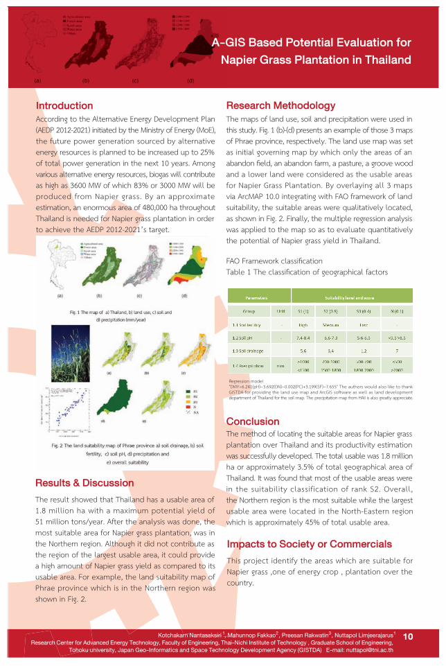
The result showed that Thailand has a usable area of1.8 million ha with a maximum potential yield of51 million tons/year. After the analysis was done, themost suitable area for Napier grass plantation, was inthe Northern region. Although it did not contribute asthe region of the largest usable area, it could providea high amount of Napier grass yield as compared to itsusable area. For example, the land suitability map ofPhrae province which is in the Northern region was shown in Fig. 2.
Research Methodology
According to the Alternative Energy Development Plan(AEDP 2012-2021) initiated by the Ministry of Energy (MoE),the future power generation sourced by alternativeenergy resources is planned to be increased up to 25%of total power generation in the next 10 years. Amongvarious alternative energy resources, biogas will contributeas high as 3600 MW of which 83% or 3000 MW will beproduced from Napier grass. By an approximateestimation, an enormous area of 480,000 ha throughoutThailand is needed for Napier grass plantation in orderto achieve the AEDP 2012-2021’s target.
10
Regression model"DMY=6.241(pH)−3.692(DN)−0.002(PC)+3.199(SF)−7.655" The authors would also like to thankGISTDA for providing the land use map and ArcGIS software as well as land developmentdepartment of Thailand for the soil map. The precipitation map from HAII is also greatly appreciate.
A-GIS Based Potential Evaluation for
Napier Grass Plantation in Thailand
1 12 3
ConclusionThe method of locating the suitable areas for Napier grassplantation over Thailand and its productivity estimationwas successfully developed. The total usable was 1.8 millionha or approximately 3.5% of total geographical area ofThailand. It was found that most of the usable areas werein the suitability classification of rank S2. Overall,the Northern region is the most suitable while the largestusable area were located in the North-Eastern regionwhich is approximately 45% of total usable area.
Impacts to Society or Commercials
This project identify the areas which are suitable forNapier grass ,one of energy crop , plantation over thecountry.
The maps of land use, soil and precipitation were used inthis study. Fig. 1 (b)-(d) presents an example of those 3 mapsof Phrae province, respectively. The land use map was setas initial governing map by which only the areas of anabandon field, an abandon farm, a pasture, a groove woodand a lower land were considered as the usable areasfor Napier Grass Plantation. By overlaying all 3 mapsvia ArcMAP 10.0 integrating with FAO framework of landsuitability, the suitable areas were qualitatively located,as shown in Fig. 2. Finally, the multiple regression analysiswas applied to the map so as to evaluate quantitativelythe potential of Napier grass yield in Thailand.
FAO Framework classificationTable 1 The classification of geographical factors
Research Backgrounds
Biocoke is a promising solid fuel made from biomass resources. Advantages Biocoke is a very useful fuel, with little or no Sulfur or ash content. Biocoke is expected to utilize as a replacement for coal coke to reduce CO
2 and pollution gases emission.
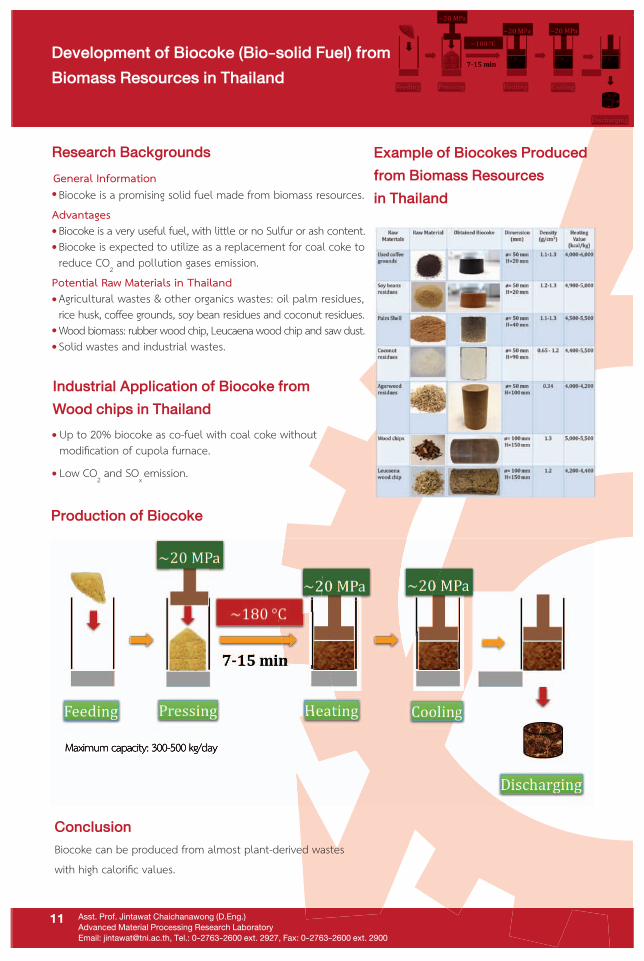
Potential Raw Materials in Thailand Agricultural wastes & other organics wastes: oil palm residues, rice husk, coffee grounds, soy bean residues and coconut residues. Wood biomass: rubber wood chip, Leucaena wood chip and saw dust. Solid wastes and industrial wastes.
Example of Biocokes Produced
from Biomass Resources
in Thailand
Conclusion
Production of Biocoke
Biocoke can be produced from almost plant-derived wasteswith high calorific values.
Maximum capacity: 300-500 kg/day
Industrial Application of Biocoke from
Wood chips in Thailand
Up to 20% biocoke as co-fuel with coal coke withoutmodification of cupola furnace.Low CO
2 and SO
x emission.
Maximum capacity: 300-500 kg/day
Development of Biocoke (Bio-solid Fuel) from
Biomass Resources in Thailand
Asst. Prof. Jintawat Chaichanawong (D.Eng.)
Advanced Material Processing Research Laboratory
Email: [email protected], Tel.: 0-2763-2600 ext. 2927, Fax: 0-2763-2600 ext. 2900
11
General Information

Research BackgroundResearch Background
Puriwat Khantiyanuwat and Wiroj Thasana
Advanced Design and Manufacturing Technology Research Laboratory (ADMT)
C407, C-Building, Thai-Nichi Institute of Technology, Bangkok, Thailand.
The plastic injection process is one of the most widelyused processes with high production efficiency.The developments of products have been influencedfrom the injection molding processes of the variousparts. Therefore, the objective of this research is topropose the influence of injection molding processesembedded magnetic parts of neodymium-nickel topredict the warpage of ABS.
Results
The results of the warpage of plastic injection moldingprocesses of ABS embedded with magnet sample parts forthe overmolding between CAE and experiments from designand development are shown in the Fig.1-2 as below.
Fig.1 Comparison results of total warpage between CAEand actual injection molding
Discussions and Conclusion
Research Methodology
From the results provides us with a systematic method toknow the values affect of the warpage of ABS. 5 requirements:filling time, packing pressure, packing time and melttemperature, which have total difference 35.34%. Onceinjected, real workpieces can be used with the paintingfixture and it can reduce the time of engraving in theproduction process from the original 20 s to only 5 seconds.
Objective
To create the mold for the plastic of polypropyleneembedded with magnet sample parts for theovermolding, and to compare the results of theappropriate parameters of CAE analysis with experimentsactually injection molding process of the plasticinjection molding embedded with magnets on thehorizontal injection molding machines.
12
Fig.2 Applying for painting fixture, Other component was madeby 3D printing
Study of Injection Molding Processes
Embedded Magnetic Parts to Predict
the Warpage of ABS

Ryo Takematsu, Wiroj Thasana and Nobuhiro SugimuraCooperation Research with Osaka Prefecture University and Advanced Design and Manufacturing Technology Research Laboratory (ADMT)Contact Address: 1771/1 Pattakarn 37, Pattakarn Road, Suanluang, Bangkok 10250
13
Modeling and Analysis of Parallel Link Robots Based
on Product Model Data Including Geometric Tolerances
Research BackgroundResearch Background
Wiroj Thasana, D.Eng
Advanced Design and Manufacturing Technology Research Laboratory (ADMT)
C407, C-Building, Thai-Nichi Institute of Technology, Bangkok, Thailand.
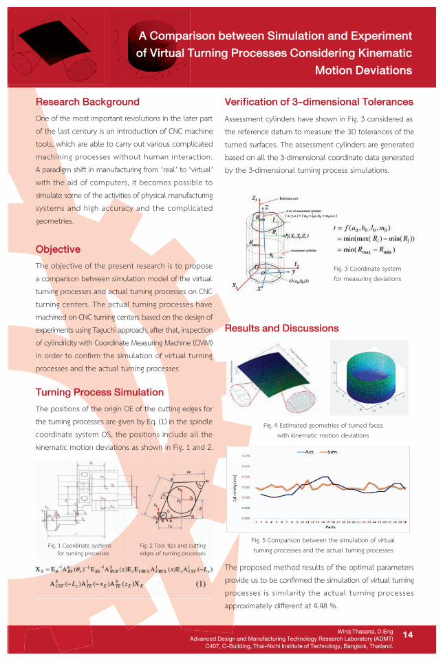
Fig. 4 Estimated geometries of turned faceswith kinematic motion deviations
Fig. 5 Comparison between the simulation of virtualturning processes and the actual turning processes
Verification of 3-dimensional Tolerances
Results and Discussions
Assessment cylinders have shown in Fig. 3 considered asthe reference datum to measure the 3D tolerances of theturned surfaces. The assessment cylinders are generatedbased on all the 3-dimensional coordinate data generatedby the 3-dimensional turning process simulations.
The proposed method results of the optimal parametersprovide us to be confirmed the simulation of virtual turningprocesses is similarity the actual turning processesapproximately different at 4.48 %.
14
One of the most important revolutions in the later partof the last century is an introduction of CNC machinetools, which are able to carry out various complicatedmachining processes without human interaction.A paradigm shift in manufacturing from ‘real’ to ‘virtual’with the aid of computers, it becomes possible tosimulate some of the activities of physical manufacturingsystems and high accuracy and the complicatedgeometries.
Objective
The objective of the present research is to proposea comparison between simulation model of the virtualturning processes and actual turning processes on CNCturning centers. The actual turning processes havemachined on CNC turning centers based on the design ofexperiments using Taguchi approach, after that, inspectionof cylindricity with Coordinate Measuring Machine (CMM)in order to confirm the simulation of virtual turningprocesses and the actual turning processes.
Turning Process Simulation
The positions of the origin OE of the cutting edges forthe turning processes are given by Eq. (1) in the spindlecoordinate system OS, the positions include all thekinematic motion deviations as shown in Fig. 1 and 2.
Fig. 3 Coordinate systemfor measuring deviations
A Comparison between Simulation and Experiment
of Virtual Turning Processes Considering Kinematic
Motion Deviations
Fig. 1 Coordinate systems for turning processes
Fig. 2 Tool tips and cuttingedges of turning processes

Research Backgrounds
The Open Vehicle Routing Problem (OVRP) is a special variant of Vehicle Routing Problem (VRP) in which vehiclesare not required to return to the depot or return with the same route or reverse order. The application instants
of OVRP are railway transportation network problem, VRP with backhaul, school bus routing problem, newspaperor milk delivery problem and contracting of goods delivery by the third party company. This research aims tosolve integrated inventory problem and open vehicle routing problem (IOVRP) of multiple depots and multipleretailers’distribution system. The developed algorithm proposes to solve for a set of routes minimizing total
travelling distance.
Asst. Prof. Anchalee Supithak
Advanced Industrial Engineering and Technology (AIE&T) Research Laboratory
Email: [email protected], Tel.: 0-2763-2600 ext. 2914, Fax: 0-2763-2600 ext. 2900
Open Vehicle Routing Concept in the
Multi-Depot and Multi-Retailer Distribution System
Research Methodology
Future Application in Thailand
Apply to the logistics’ decision program based on
the OVRP concept when the distribution networkuse resources allocation policy.
15
Delivery route for odd-weeks
Delivery route for even-weeks
Example of Open Vehicle Route
Conclusion
The OVRP application is advantage in giving lowertraveling distance comparing to the classical VRP.
This approach is practical in logistics and supply chain
management since the inventory and transportation
problems are cons idered for developing
replenishment schedule.
Research Backgrounds
General Information
Research Backgrounds
General Information
Asst. Prof. Dr. Pornchai Nivesrangsan
Advanced Industrial Engineering and Technology (AIE&T ) Research Laboratory
Email: [email protected], Tel.: 0-2763-2600 ext. 2927, Fax: 0-2763-2600 ext. 2900
Rotating machine health monitoring is a method topredict machine states and prevent machine form
severe damage.
Advantages of Low-cost condition
monitoring system
Predict a current machine state. Prevent machine form severe damage.Minimise unscheduled downtime.Improve repair time
Increased machine life
Improve product quality
Reduce product cost
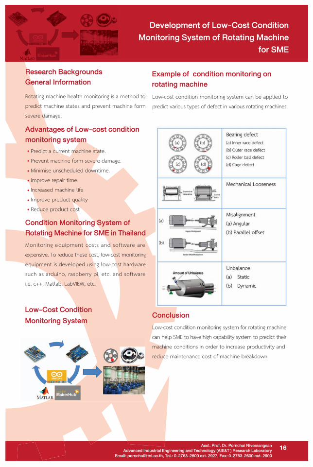
Example of condition monitoring on
rotating machine
Low-cost condition monitoring system can be applied to
predict various types of defect in various rotating machines.
Condition Monitoring System of
Rotating Machine for SME in Thailand
Monitoring equipment costs and software areexpensive. To reduce these cost, low-cost monitoringequipment is developed using low-cost hardware
such as arduino, raspberry pi, etc. and softwarei.e. c++, Matlab, LabVIEW, etc.
Conclusion
Low-cost condition monitoring system for rotating machine
can help SME to have high capability system to predict theirmachine conditions in order to increase productivity and
reduce maintenance cost of machine breakdown.
Low-Cost Condition
Monitoring System
16
Development of Low-Cost Condition
Monitoring System of Rotating Machine
for SME

Research Backgrounds
The process of ruler calibration is a time consuming process
and the operator will got an eye stress since he have to
decision the center of measuring line and the middle of the
calibrator camera-picture.
Asst. Prof. Dr. Warakom Nerdnoi
Advanced Industrial Engineering and Technology (AIE&T) Research Laboratory
Email: [email protected], Tel.: 0-2763-2600, Fax: 0-2763-2600 ext. 2900
Example of Open Vehicle RouteDelivery route for odd-weeks Delivery route for even-weeks
Future Application in Thailand
Apply to all Calibration Laboratory that calibrate Ruler,Measuring tape etc.
Conclusion
There is the integration of high-precision mechanical system,motor controlling, vision technique and computer programminginto the real automation machine.
Example of Open Vehicle RouteExample of Open Vehicle RouteDelivery route for odd-weeks Delivery route for odd-weeks Delivery route for even-weeksDelivery route for even-weeks
17
Automatic Ruler Calibrator
by Vision Technique

IntroductionIntroduction
Phaisarn SUDWILAI, Pattanachai KONGUDOM and Phacharawat CHINDAMANEE
Advanced Magnetics and Motor Drive Research Laboratory : AMDRL
E-mail :[email protected] AMDRL-LAB, Thai-Nichi Institute of Technology,BKK
Solar charge controller helps in increasing the efficiencyof the solar power transferred to the battery. The main
problem in solar charger system is to maintain the DCoutput power from the solar panel as constant.
This research presents a design and implementation
of maximum power point tracking(MPPT) techniquesfor solar charge controller using solar panel 20 watt
21.5V and DC to DC Buck converter.
Results and Discussion
Figure 1 represent the schematic drawing s research,the attention will be focused in maximum power point
tracking (MPPT) using the modified and adaptive ofperturb and observe techniques, considering severalirradiation conditions. A photograph of the system
is shown in Fig. 2. Figure 3 shows the I-V and P-VCharacteristic curve of the system prototype at the
condition of power maximum is 17.0665 watt.
Fig. 1. Block diagram of experimental setup
Fig. 2. Photograph of system prototype
Fig. 3. I-V and P-V characteristic curve
Conclusion
18
A DC to DC Buck converter was designed using MPPTtechniques for varied duty cycle of gate drive circuit.
A model was set up for the feasibility analysis, anda system prototype was manufactured for experimental
confirmation. The experimental results from the
analysis of the prototype performance demonstrated
the efficiency of the control design.
MPPT Solar Charge Controller
Introduction
Competition Objectivity
Siriluck Anekboonlab and Computer Engineering students
Computer, Robotics and Technology Research Laboratory (CERT)
Faculty of Engineering, Thai-Nichi Institute of Technology, Tel: 0-2763-2600, Fax: 0-2763-2600 ext. 2900
19
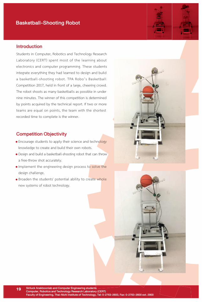
Students in Computer, Robotics and Technology ResearchLaboratory (CERT) spent most of the learning aboutelectronics and computer programming. These students
integrate everything they had learned to design and build
a basketball-shooting robot. TPA Robo’s BasketballCompetition 2017, held in front of a large, cheering crowd.The robot shoots as many basketballs as possible in undernine minutes. The winner of this competition is determined
by points acquired by the technical report. If two or more
teams are equal on points, the team with the shortestrecorded time to complete is the winner.
Encourage students to apply their science and technology
knowledge to create and build their own robots. - Design and build a basketball-shooting robot that can throw a free-throw shot accurately.
- Implement the engineering design process to solve the
design challenge.
- Broaden the students' potential ability to create whole new systems of robot technology.
Basketball-Shooting Robot

Research and Academic Services Department,
Thai-Nichi Institute of Technology
1771/1 Pattanakarn Road, Suanluang, Bangkok 10250
Tel: +66 (0) 2763 2600 ext. 2752, 2704 Fax. +66 (0) 2763 2754
Email: [email protected] website: www.tni.ac.th