Embed Size (px)
Citation preview

C III 2
Integrated solutions for building prestressing by post-tensioning
D e s i g n , B u i l d , M a i n t a i n
C III 2 - 11/12
Contents
Post-tensioning benefits
Prestressing design
Multi-strand prestressing anchor
Single-strand prestressing anchor
Installation works
p3
p6
p8
p12
p14
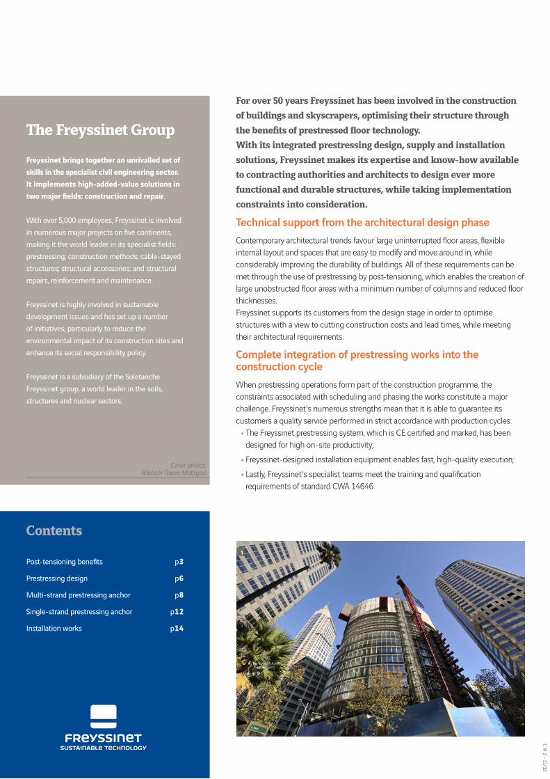
For over 50 years Freyssinet has been involved in the construction of buildings and skyscrapers, optimising their structure through the benefits of prestressed floor technology.With its integrated prestressing design, supply and installation solutions, Freyssinet makes its expertise and know-how available to contracting authorities and architects to design ever more functional and durable structures, while taking implementation constraints into consideration.
Technical support from the architectural design phaseContemporary architectural trends favour large uninterrupted floor areas, flexible internal layout and spaces that are easy to modify and move around in, while considerably improving the durability of buildings. All of these requirements can be met through the use of prestressing by post-tensioning, which enables the creation of large unobstructed floor areas with a minimum number of columns and reduced floor thicknesses.Freyssinet supports its customers from the design stage in order to optimise structures with a view to cutting construction costs and lead times, while meeting their architectural requirements.
Complete integration of prestressing works into the construction cycleWhen prestressing operations form part of the construction programme, the constraints associated with scheduling and phasing the works constitute a major challenge. Freyssinet's numerous strengths mean that it is able to guarantee its customers a quality service performed in strict accordance with production cycles:
• The Freyssinet prestressing system, which is CE certified and marked, has been designed for high on-site productivity;
• Freyssinet-designed installation equipment enables fast, high-quality execution;• Lastly, Freyssinet's specialist teams meet the training and qualification
requirements of standard CWA 14646.
The Freyssinet Group
Freyssinet brings together an unrivalled set of skills in the specialist civil engineering sector. It implements high-added-value solutions intwo major fields: construction and repair.
With over 5,000 employees, Freyssinet is involved in numerous major projects on five continents, making it the world leader in its specialist fields: prestressing; construction methods; cable-stayedstructures; structural accessories; and structural repairs, reinforcement and maintenance.
Freyssinet is highly involved in sustainable development issues and has set up a number of initiatives, particularly to reduce the environmental impact of its construction sites and enhance its social responsibility policy.
Freyssinet is a subsidiary of the Soletanche Freyssinet group, a world leader in the soils, structures and nuclear sectors.
Cover photos:Telecom Tower, Malaysia
1

C III
2 -
11/1
2
3
2
Reinforced concrete
Prestressed concreteCrossover point
1.4
1.3
1
0.9
0.8
1.1
0.7
1.2
6 7 8 9 10
Freyssinet has developed compact prestressing systems suitable for prestressing thin elements. These systems make it possible to significantly improve the slabs commonly used in buildings.
Main benefits• Larger slab spans require fewer columns, providing great freedom in terms of
layout;• Depending on slab type, elimination of soffits or reduced floor thicknesses.
The saving in height thus obtained can result in an increase in the number of storeys in the structure;
• Savings in materials (concrete and steel);• Foundations are smaller and simpler;• Shorter lead times due to fast installation.
As well as:• Elimination of deflection in routine service;• Reduction in number or even elimination of slab contraction joints and floor
expansion joints;• Better control of shrinkage cracking for improved watertightness and hence
greater durability.
The use of floors prestressed by post-tensioning results in a 20% reduction in greenhouse gas emissions compared with traditional reinforced concrete designs.
A variety of applicationsFreyssinet prestressing systems can be used in floors, foundation slabs and building transfer structures, as well as in industrial slabbing systems. They are a cost-effective, reliable solution for optimising a wide range of structures:
• Residential buildings;• High-rise office buildings;• Shopping centres;• Underground or above-ground car parks;• Hospitals;• Schools;• Business centres;• Industrial buildings;• Sports halls;• Docks, etc.
1 - Blige Street Tower (Australia)2 - Park Towers (UAE)
Post-tensioning benefits
Cost comparison for floor systems as a function of span (m)
Reduction in the quantity of passive reinforcements: -66%
Reduction in the quantity of concrete: -25%

C III 2 - 11/12
4
Building floors
These are often thin slabs, continuous over several spans and resting on columns at certain points. Prestressing increases slab bending strength relative to permanent loads and variable loads. Tendons can be arranged in two orthogonal directions or in a preferential direction with added passive reinforcements at right angles.The benefits brought about by prestressing in building floors are numerous:
• For high-rise buildings:- Height between floors reduced to the minimum, enabling material savings
to be achieved in vertical elements, structural or otherwise;- A shorter construction cycle on each storey, reducing the overall project
lead-time and the amount of formwork;- The lowest possible floor mass, reducing the loads transmitted to the
foundations and loads in cross-bracing when subject to seismic stress.
• For buildings with large plan dimensions:- Larger column-free areas, which are more functional and allow for better
use of space;
- For certain commercial or industrial buildings, deflection and crack opening are strictly controlled.
Foundation slabs
Foundation slabs are in direct contact with the ground and enable buildings to be erected on soils with poor mechanical properties.The undulating layout of the prestressing compensates for permanent and variable loads. The permanent compression of the concrete also improves foundation slab sealing against any water ingress.
A variety of applications
1 - Mirage Towers (Mexico)2 - Prestressed floor - Cardinal Place (Great Britain)3 - Foundation slab - Aster Building (Saudi Arabia)4 - Transfer slab - The Elysian (Ireland)5&6 - Multimodal platform - Botany Bay (Australia)
1
3

C III
2 -
11/1
2
5
Transfer slabs
Transfer structures are often very thick slabs, subject to heavy loading, which absorb the loads from columns above that are not aligned with the columns below. They are generally used in high-rise buildings to clear a space without load-bearing elements or to effect the transition into car park levels.Prestressing enables the height of transfer slabs to be substantially reduced; in certain cases Freyssinet will be able to offer high-strength tendons equipped with anchors from its C system for civil engineering structures.
Industrial slabs
These slabs bear directly on the foundation soil. The prestressing tendons are straight, centred and arranged in both directions. They allow for the reduction or even elimination of passive reinforcements in the main run of the slab. They improve bending strength and ensure shrinkage cracking is kept under control.Freyssinet builds very large industrial slabbing areas, while reducing in number of or even eliminating contraction joints. These joints are vulnerable to wear due to traffic and their elimination is particularly appreciated where automated conveyor systems are installed, for which surfaces must be absolutely flat.The permanent compression of the concrete by prestressing provides concrete foundation slabs with improved watertightness.Phased work means that disruption can be reduced to a minimum for the operator.
5
4
6

C III 2 - 11/12
6
Prestressing designWorking closely with the architect and the design consultants in charge of the overall design of the project, Freyssinet revises the design then conducts a detailed study of the floors, supplying all the calculation data required for sizing the vertical elements in particular. Freyssinet is also available to put forward optimised variants of the basic reinforced concrete systems.In order to reduce the thickness of the slabs and fully or partly eliminate passive reinforcements, Freyssinet uses professional, recognised 2D or 3D finite element design software that complies with regulations and local practice, in order to determine floor dimensions.Right from the preliminary phase, these design programs make it possible for quantities to be fully verified and calculated precisely: • for slab floors, punching shear strength due to permanent and service loads; • for slabs on beams, deflection due to service loads on their own, or even shear
forces or cracks opening up.
Bonded prestressing
Prestressing by post-tensioning is generally of the bonded type, i.e. made up of steel strands housed in a duct, which is injected with cement grout after tensioning. This arrangement enables strand loads to be transferred to the concrete structure by bonding, which allows for passive reinforcement to be optimised and significantly reduced.Among other benefits, internal prestressing in concrete makes it possible to guarantee an improvement in fire protection and ensures that tendons can be re-anchored in the event of openings being made at a later date.
Unbonded prestressing
For projects involving specific stresses, Freyssinet can also offer unbonded prestressing made up of greased sheathed strands installed in the reinforcement prior to concreting. The strands remain mechanically independent of the structure throughout the service life of the structure and slide freely in the concrete.Unbonded prestressing reduces the space occupied in the thickness of the slab and offers greater freedom in horizontal alignment.
Prefabrication
If appropriate, Freyssinet can put forward a mixed system combining prefabricated elements with prestressed elements cast in situ to optimise lead times and reduce costs.
1
1 - Prestressing layout2 - Graphic depiction of deformation
2

C III
2 -
11/1
2
7
Prestressing designRules for preliminary sizing of prestressed concrete floors
The table below describes the main types of prestressed concrete floors and can be used for fast preliminary sizing.
DiagramService load
(kN/m²)
L/h ratio(with passive reinforce-
ments)
Slab floor(load-bearing in both directions)
Relatively light or medium service loads.
1.5 45
2.5 40
5 35
Slab floor with capitalsSame applications but for larger spans and medium service loads.Capital drop between 0.75 h and 1.5 h and overhang between 3 h and 6 h.
1.5 50
2.5 45
5 40
Slab load-bearing in a single direction
Recommended for floors with a prevailing span in one direction.
1.5 55
2.5 45
5 35
Slab load-bearing in both directions
Spans approximately equal in both directions.
1.5 70
2.5 60
5 50

C III 2 - 11/12
8
Type B Active/Passive AnchorsThe Freyssinet type B prestressing system consists of internal prestressing tendons with 3 to 5 T13 or T15 strands.Type B anchors consist of active or passive anchors; they are made up the following elements:• A cast trumplate embedded in concrete that distributes the prestressing load into
the structure;• A block and its jaws, bearing on the trumplate, which anchors the strands.
The construction provisions stipulated in the project must comply with current local regulations, as well the technical specifications, Freyssinet procedures and technical approval, as appropriate, relating to the use and installation of a type B prestressing system.
Bonded prestressing
In this configuration, type B anchors are used with uncoated strands in a metal or plastic corrugated flat sheath, for ease of insertion into thin elements. The strands are threaded into their ducts prior to concreting in order to overcome duct crushing problems, which might subsequently impede strand threading.Once the strands have been tensioned and excess lengths cut off, the duct is injected with cement grout.
Unbonded prestressing
For specific projects, system B anchors can be used with strands protected with grease, coated with an individual HDPE sheath, in order to effect unbonded prestressing. The strands are then incorporated directly into the reinforcement, before concreting.Once the strands have been tensioned and excess lengths cut off, the anchor is injected with cement grout.
Multi-strand prestressing anchor
Recess Trumplate Smooth sheath
Corrugated sheath Anchor block
A B C F G H1 H2 H1 H2 J K L
3B13 124 187 208 117 124 40 20 58 21 60 46 111
3B15 164 227 248 147 164 70 20 58 21 57 54 138
4B13 164 227 248 147 164 70 20 58 21 53 55 155
4B15 202 265 286 180 192 70 20 75 21 59 54 181
5B13 202 265 286 180 192 70 20 75 21 50 55 187
5B15 255 318 339 221 245 90 20 90 21 58 54 223
Dimension
Anchor
T13 JAWT15 JAW
SEALING FILLER
GROUTING TUBE
ADHESIVE STRIP
TRUMPLATE
ANCHOR BLOCK
FLAT SHEATH
AnchorDimension
4B133B153B13
227227164
164 147147 164
164
CBA
187124
F G
117 12470
5357
H1 J
60
H2
5554
K
46
4B15 265202 180 192 59 545B13 265202 180 192 50 555B15 318255 221 245 90 58 54
202020202020
40
707070
155138
L
111
181187223
RECESS TRUMPLATE SMOOTH SHEATH ANCHOR BLOCK
208248248286286339
1053
130
6050
KLGABC
F
J
H2 (in
t)H1
(int)
8083
31
M12
58
H1 H2
90
212121212121
58
587575
CORRUGATED SHEATH
1
2
3

C III
2 -
11/1
2
9
Prestressing strandsThe table below shows the main features of the most common strands that can be used with the Freyssinet prestressing system.
Anchor layouts
Anchors must be positioned at an adequate distance from the edge and with a minimum centre-to-centre spacing from each other. These distances are obtained using the dimensions from the test assemblies created under the European Technical Approval procedure (ETA).
Hoop reinforcement
The concentrated forces applied by the prestressed units require the installation of hoop reinforcement in the vicinity of the anchors in the case of concrete structures. This local reinforcement comprises anti-burst reinforcement and additional reinforcements as set out in the European Technical Approval document. The diagram opposite illustrates an example of a local reinforcement arrangement.The reinforcement given in the tables must be supplemented in most cases by general reinforcements (not shown on the drawings), which are the minimum requirement against cracking and general balance reinforcements. The project designer must check the general balance of the anchor zones.
Multi-strand prestressing anchor
1 B500 steel 2 B500 steel
Unit Pitch d N A B Co e C D
3B13 60 8 4 120 200 45 8 120 120
4B13 60 10 6 140 240 45 8 140 160
5B13 60 10 6 140 260 45 8 140 190
3B15 60 10 6 140 240 45 8 140 160
4B15 60 10 6 140 280 45 8 140 190
5B15 60 12 6 140 320 45 10 140 240
Name ClassMPa
Nominal reinforcement
diameter(mm)
Nominal reinforcement cross-section
(mm²)
Nominal weight(kg/m)
Guaranteed breaking load
(FpK Kn)
Elastic limit(Fp0.1 kN)
pr EN10138-3
1,770
12.5 93 0.73 165 145
12.9 100 0.78 177 156
15.3 140 1.09 248 218
15.7 150 1.18 265 234
1,860
12.5 93 0.73 173 152
12.9 100 0.78 186 164
15.3 140 1.09 260 229
15.7 150 1.18 279 246
a Typical elongation under maximum load for all strands is ≥ 3.5%a Maximum relaxation at 1,000 hours at 0.7 fpk for all strands is ≤ 2.5%
1 - 3D views of 3B15 and 5B15 anchors2 - Overall dimensions3 - 4B15 anchor complete with sheath4 - Food processing plant (Singapore)5 - Hoop reinforcement
Co
Pasd
N x Pas
2
1B
A
D
C
e
21
60
60
60
60
60
605B15
5B13
4B15
10
12
10
6
6
6
3B15
4B13
3B13
UNITÉ
10
10
8
6
6
4
d NPas
120
140
140
140
140
140
240
320
280
260
240
200 45
B CoA
1 (Acier B500)
45
45
45
45
45
8
Ce D
2 (Acier B500)
8
8
8
8
10
120
140
140
140
140
140
160
240
190
190
160
120
4
5

C III 2 - 11/12
10
Type B Active/Passive Anchors
Formwork accessoriesFreyssinet offers a full range of accessories to create the recesses used for subsequent sealing of the anchors, i.e. for a break in a shuttering face or for a raised anchor above the slab.
Bonded prestressing sheathPrestressing sheaths are either flat smooth metal sheaths (the most commonly used type) or round corrugated metal or plastic sheaths (CE marked). As from the design phase, the radii of curvature in the deviated zone and the coefficients of friction must be validated by Freyssinet.
TensioningTendons with type B anchors are tensioned using single-strand hydraulic jacks equipped with a hydraulic anchor jaw locking-off system as an option. Initial forces before and after transfer must comply with local regulations and with the Freyssinet working documents.The tensioning operation cannot start unless the compression strength of the concrete measured on site, in the vicinity of the anchor zone, is greater than the value specified for the project.
SealingOnce the tendons have been tensioned and the strands cut to length, the anchors are generally protected by sealing in concrete.
Cement grout and injectionPrestressing strands, if not individually sheathed and greased, are protected by injecting the duct containing them. The filler is a cement grout that generates a passivation layer on the surface of the steel, which protects it against corrosion. Based on laboratory studies and on-site suitability tests, Freyssinet has specified and qualified a prestressing grout suitable for the project conditions.
Multi-strand prestressing anchor
1 - Plastic formwork box2 - Installing the sheathing3 - View of anchor after sealing4 - Type G anchor5 - Type N anchor6 - Installing a type G anchor
1
2
3

C III
2 -
11/1
2
11
Multi-strand prestressing anchorType G and N Embedded Passive AnchorsThe type B anchor system can be used in combination with two types of passive anchor embedded in concrete:- the type G bulb anchor, which operates by bonding;- the type N anchor, which uses an individual plate on
which an extruded sleeve bears
Type G embedded anchorThe type G anchor is an anchor that operates by bonding. The end of each strand is preformed so as to create an anchor bulb.
Type N embedded anchorIn the type N anchor, each strand has an extruded sleeve, which bears individually on a steel plate.Each one of these anchors is used with its specific hoop reinforcement.
4
Fixed anchors
Extruded sleeve
Steel plate
Oblong sleeve tube
Mastic
Vent tube
Flat sheath
Bulb
Oblong sleeve tube
Mastic
Vent tube
Flat sheath
Fixed anchors
Extruded sleeve
Steel plate
Oblong sleeve tube
Mastic
Vent tube
Flat sheath
Bulb
Oblong sleeve tube
Mastic
Vent tube
Flat sheath
5

C III 2 - 11/12
12
Type F Single-Strand Active/Passive AnchorThe 1F15 single-strand anchor is used to effect unbonded prestressing. It consists of an active anchor, which is also used as a passive anchor by means of pre-locking.
Composition of the 1F13/15 system
• The 1F13/15 anchor is made up of the following elements:- A cast anchor body (with its jaws) embedded in the concrete, which
distributes the prestressing load into the structure and acts as an anchor for the strands;
- A plastic connecting tube that provides permanent protection for the uncoated part of the strand;
- A plastic cover filled with grease that provides permanent protection for the jaws;
- As an option, formwork accessories to create the anchor recess and enable sealing after tensioning.
• The bands forming part of the anti-burst reinforcement;
• The protected sheathed sliding prestressing strands.
Unbonded prestressingThe strands are incorporated directly into the reinforcement, before concreting.
Single-strand prestressing anchor
1 to 3 - 1F13/15 single-strand unit4 - Car park slab - Toulouse (France)5 - NB1F15 pre-locked anchor6 - Anchor with extruded sleeve7 - Standard layout prior to concreting - Lanslebourg (France)
3
Non-shrink mortar
Threaded plug
Grease
O-ring
Connecting tube
Adhesive tape
Shape of recess
1
2
4
Non-shrink mortar
Threaded plug
Grease
O-ring
Connecting tube
Adhesive tape
Shape of recess

C III
2 -
11/1
2
13
Non-shrink mortar
Threaded plug
Grease
O-ring
Connecting tube
Adhesive tape
Shape of recess
Non-shrink mortar
Threaded plug
Grease
O-ring
Connecting tube
Adhesive tape
Shape of recess
Single-strand prestressing anchorSingle-Strand Passive Anchors embedded in concrete1F13/15 active anchors can be used in combination with two types of passive anchor embedded in concrete:- The pre-locked NB1F15 mechanical anchor;- The type N anchor, which uses an individual plate on
which an extruded sleeve bears.
Bearing plate
T15D sleeve
Pre-locked jaws Grease
Spring
Type N embedded anchorIn the type N anchor, each strand has an extruded sleeve, which bears individually on a steel plate.
Type NB 1F13/15 embedded anchorThe NB 1F13/15 embedded anchor is similar to the 1F13/15 active anchor. When used as an embedded anchor, the wedge is pre-locked using a jack before the anchor is installed in the formwork. It is then fitted before concreting with a plug filled with grease screwed onto the back of the anchor and fitted with a jaw retaining spring that eliminates any risk of the strand sliding.
Standard layout• Mesh in lower plane• Even distribution of monostrands in one direction• Grouping of monostrands along rows of columns• Top bar reinforcement in upper plane• Incorporation of services (electricity, rainwater, underfloor heating, etc.)
65
7

C III 2 - 11/12
14
Freyssinet acts as your partner for all your projects, offering integrated solutions that ensure a turnkey service and guarantee quality work carried out in compliance with safety rules.
Prestressing is installed in a number of stages:
1. Formwork installation2. Installation of lower mesh and lower beam reinforcements3. Installation of active anchors at concreting breaks3a. Bonded prestressing: duct installation and strand threading3b. Unbonded prestressing: installation of greased sheathed strands, which
may be prefabricated4. Creation of passive anchors5. Creation of tendon profile using plastic supports6. Installation of upper reinforcements7. Inspection of prestressing and reinforcements by a Freyssinet manager8. Concreting of slab in the presence of a Freyssinet manager9. Tensioning to 25% if necessary10. Tensioning to 100%11. Elongation monitoring12. Stripping formwork from slab13. Cutting strands to length14. Sealing of anchor recesses15. Cement grouting of ducts in the case of bonded prestressing
Specialist teamsFreyssinet prestressing specialists are certified through internal training and provide the assurance that our work is carried out correctly in compliance with CWA No.14646 voluntary certification requirements. We therefore undertake to supply and install the prestressing kit in compliance with our European Technical Approval.
Installation works1
2
3

C III
2 -
11/1
2
15
Rapid installation
The small quantity of passive reinforcements required compared with a reinforced concrete solution speeds up construction cycles.Tensioning concrete to 25% after a short period of ageing (24 hours) enables slab cracking to be checked and guarantees that crack openings do not exceed 0.3 mm.Tensioning prestressing tendons to 100% after around 3 days enables formwork to be stripped rapidly and permanently from horizontal elements, which will be capable of taking up 100% of the loads for which they have been sized.
Strength on tensioning
The first tensioning of the tendon to 25% of the final tensioning load may be carried out if the concrete behind the anchor has reached a compressive cylinder strength of at least:
• 10.5 MPa for an F13 anchor,• 9.5 MPa for a B13 anchor,• 10.5 MPa for an F15 anchor,• 11.0 MPa for the B15 system.
Freyssinet equipment
Ease of installation is one of the leading aspects of our approach, meaning that we use elements that can be carried by hand, thus reducing crane usage time. The various items of equipment required to install prestressing are as follows:
• Single-strand jacks with around 25 kg capacity;• Portable engine-powered or electric tensioning pumps;• Trumplate support negatives;• Extrados tensioning recess negatives;• Jacks for creating passive bulbs;• Sleeve extrusion presses;• Wedge pre-locking jacks;• Mixing and grouting unit.
Installation works
1 - Sheath installation2 - Embedded passive anchors3 - Formwork box for extrados active anchor4 - Anchor and its hoop reinforcement at slab edge5 - Concreting6 - Individual strand tensioning (France)
4
5
6

© 2014 Freyssinet - The text, photos and other information contained in this catalogue are the property of Freyssinet. Any reproduction, display or other use without the prior consent of Freyssinet is prohibited. Freyssinet promotes the use of paper pulp from sustainably managed forests. The paper used in this catalogue is certified in accordance with the stringent rules of the PEFC (Program for the Endorsement of Forest Certification).Publication: 09/2014 - C III 2 - Printed in France
AMERICAS • Argentina • Brazil • Canada • Chile• Colombia • Mexico • Panama • Salvador • United States • Venezuela • EUROPE • Belgium • Bulgaria •Czech Republic • Denmark • Estonia • France • Hungary • Iceland • Ireland • Latvia • Lithuania • Luxembourg • Macedonia • Netherlands • Norway • Poland •
Portugal • Romania • Russia • Serbia • Slovenia • Spain • Sweden • Switzerland • Turkey • United Kingdom • AFRICA AND MIDDLE EAST • Abu Dhabi • Algeria • Dubai • Egypt • Jordan • Kuweit • Morocco • Oman • Qatar • Saudi Arabia • Sharjah • South Africa • Tunisia • ASIA • Hong Kong • India • Indonesia •
Japan • Macau • Malaysia • Pakistan • Singapore • South Korea • Taiwan • Thailand • Vietnam • OCEANIA • Australia • New Zealand
Over 60 locations worldwide
www.freyssinet.com
Follow us on: