Embed Size (px)
Citation preview

P A N O R A M A
9,500 CMC in NewportThe construction of the NewportSouthern Distributor Road by the Morgan-VINCI joint venture inthe United Kingdom, is nowadvancing quickly. The soiltreatment work in port areas andin the adjacent tip is being doneby Ménard Soltraitement, and will be completed in August 2003.A total of 9,500 controlledmodulus columns (about 130,000 m) will be realised.
Freyssinet will carry out the prestressing work for theKudankulam nuclear power sta-tion in the State of Tamil Nadu,India. This power station islocated in the southern part ofthe country and is being built forthe Nuclear Power Corporation ofIndia Limited (NPCIL). Two reac-tors will be installed and it will be
the largest in the country, with2,000 MW. The civil engineeringworks started at the beginning of2003. Construction will be completed in December 2004,and commissioning by 2007.Freyssinet is working for the Russian Atomstroyexport Com-pany, and will install 514 type55C15 anchors supplied by the
PPC Company and injected withcement grout before tensioning,and 2,700 t of unbonded strands.The advantages of this solutionare that the resulting prestressingis fully measurable, if necessaryeach strand can be individuallyretensioned or replaced, and it provides perfect protectionagainst corrosion.
2,700tonnes of prestressing
Prestressed floors for the Cape bank
Twin bridges in DubaiA marina is being built in the heart of thesouthern district of Dubai near Jebel Ali,(United Arab Emirates). It is linked to theArabian Gulf at each end. Freyssinet Gulf issupplying and implementing prestressingfor two identical bridges that cross theMarina. Each 208 m long structure com-prises 40 m long end spans and a 128 mlong central span. They are prestressedusing 37C15 anchors with galvanized steelducts with around 300 t of post-tensioningstrand in each. The project also includesthe construction of some 4,000 sqm of Freyssisol Reinforced Earth® retainingwalls. The structures should be completedby end of September.
When Nedcor Bank decided to extend itsRegional Headquarters in Cape Town (SouthAfrica), they did so by purchasing the old build-ing next door. As the height of the floors was notthe same between both buildings, a four-levelcar park was constructed with a shoppingarcade at ground level and seven levels of officefloors. Freyssinet Posten supplied and installed30 tonnes of unbonded strands and 3,120anchors for the post-tensioned concrete floors.
4-star TerraPlusThe Pueblo Bonito SunsetBeach hotel in LowerCalifornia, Mexico, is a luxury complex built interraces on a set of 17 platforms thatinvolved the constructionof 10,000 m2 of retainingwalls and the use of new TerraPlus squarepanels. Tierra Armada
has been working in close co-operation with the main contractor because the region is subject to earthquakes and the nature of the soils has made the design of the structures very complicated. The end result is an aesthetically pleasing project.
May - August 2003 Soils & Structures 3
PANORAMA
I N B R I E FEXPRESS SITES
KOREAFreyssinet Korea willparticipate in theconstruction of 13,600 m2 of TerraClassretaining walls for theMungok-Mureung road inthe north of the country.
FRANCESTTP, a Freyssinetsubsidiary, has built a 6 m high temporarydiaphragm wall in Lyons toenable the constructionof an underground car park beneath an office building.
MALAYSIAReinforced Earthparticipated inconstruction of a 3,360 m2, 9 m highplatform wall in theProvince of Kedah, for the development of a water sports andtourist activities area.
RION-ANTIRION: FIRST STAY CABLESThe first stay cables forthe Rion-Antirion bridge in the Gulf of Corinth inGreece are beinginstalled. The 2,252 mlong main structure isbuilt by a French-Greekgroup led by VINCIConstruction GrandsProjets, and will use 368stay cables. Freyssinet isparticipating in the installation of the3,800 t of stay cables.
1,200 tonnes of shotcreteA Freyssinet team composed of up to 25 persons has beenperforming strengthening work for the Saint-Gobain -Desjonquères factory in Le Tréport, in the Seine-Maritimedepartment in France, over the last seven months, after itwas damaged by a fire. Freyssinet used shotcrete to recre-ate 63 beams in this project to reconstruct and strengthenthe structure of this two-storey building. These beamswere then prestressed with unbonded single strands. Thiswork was done without interrupting production on thefirst floor of the plant. This project, started in September2002, was completed at the end of April, at about thesame time that the repair work of 1,800 m2 of externalsurfaces started. It involved the placement of 1,200 t of shotcrete over an area of 2,000 m2 and is one of thelargest building projects ever undertaken by Freyssinet.
▼▼
▼▼
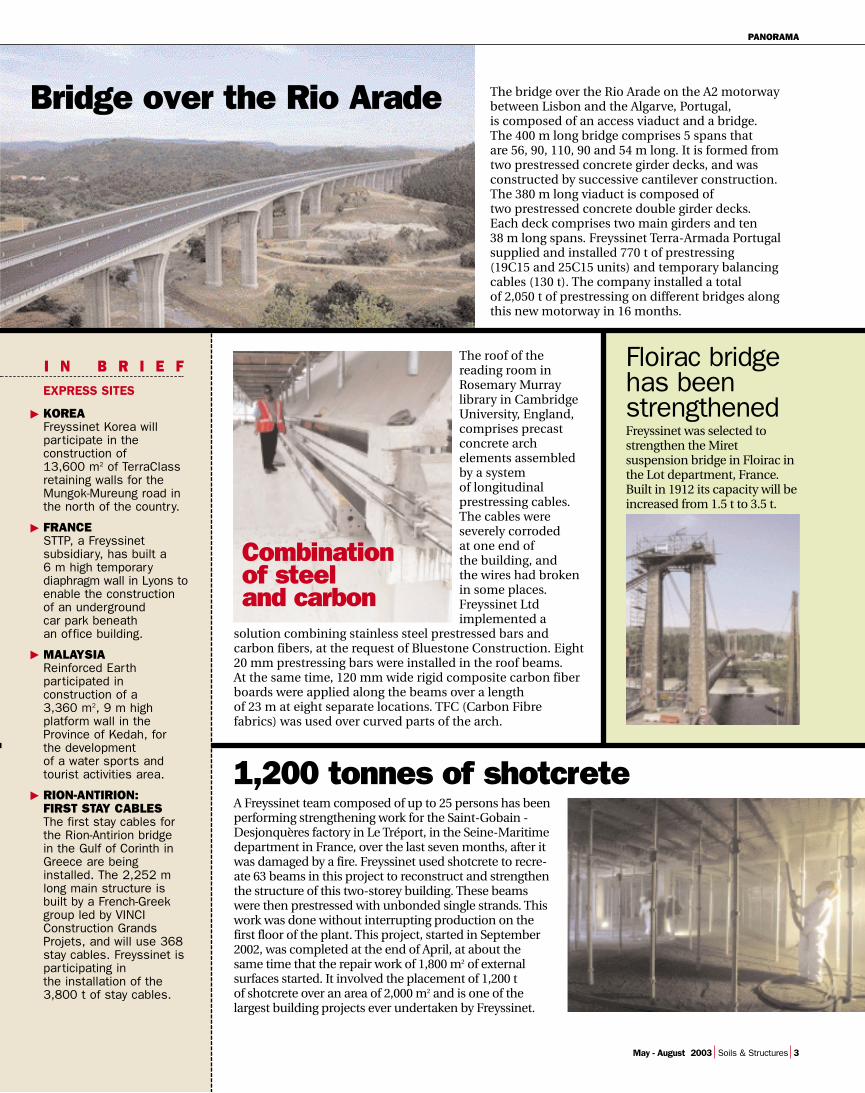
The bridge over the Rio Arade on the A2 motorwaybetween Lisbon and the Algarve, Portugal, is composed of an access viaduct and a bridge. The 400 m long bridge comprises 5 spans that are 56, 90, 110, 90 and 54 m long. It is formed fromtwo prestressed concrete girder decks, and was constructed by successive cantilever construction.The 380 m long viaduct is composed oftwo prestressed concrete double girder decks. Each deck comprises two main girders and ten 38 m long spans. Freyssinet Terra-Armada Portugalsupplied and installed 770 t of prestressing (19C15 and 25C15 units) and temporary balancingcables (130 t). The company installed a total of 2,050 t of prestressing on different bridges alongthis new motorway in 16 months.
Bridge over the Rio Arade
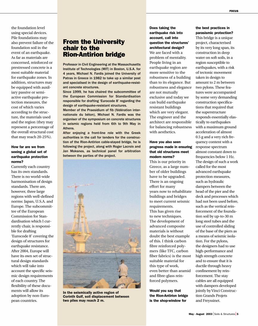
The roof of thereading room inRosemary Murraylibrary in CambridgeUniversity, England,comprises precastconcrete archelements assembledby a system of longitudinalprestressing cables.The cables wereseverely corroded at one end of the building, and the wires had brokenin some places.Freyssinet Ltdimplemented a
solution combining stainless steel prestressed bars andcarbon fibers, at the request of Bluestone Construction. Eight20 mm prestressing bars were installed in the roof beams. At the same time, 120 mm wide rigid composite carbon fiberboards were applied along the beams over a length of 23 m at eight separate locations. TFC (Carbon Fibrefabrics) was used over curved parts of the arch.
Combination of steel and carbon
Floirac bridgehas been strengthenedFreyssinet was selected tostrengthen the Miretsuspension bridge in Floirac inthe Lot department, France.Built in 1912 its capacity will beincreased from 1.5 t to 3.5 t.

F O C U S
After the symposium of the fédérationinternationale du béton (fib) held in Athensfrom 6th-9th May, its organiser considers theevent and talks about parasismic protection.
Soils and Structures: Howimportant was theAthens fib Symposium?Michael N. Fardis. - Veryimportant. There wereover 520 delegates, 310of which were interna-tional visitors, despitethe unfavourable inter-national context. From a technical point of view,the Symposium was agreat success, with 207 conferences, led by topclass specialists.
What were its greatestachievements?The highlighting of ‘dry joints’ for precaststructures was one of the most remarkable suc-cess stories presented atthe Symposium. Discreteprecast concrete ele-ments are in direct con-tact and connected bymeans of unbondedinternal prestressing ten-dons. If there is an earth-quake, a structuredesigned in this waydeforms and then returnsto its original shape when the shock is over. Thisdesign creates a building
that is as earthquake-resistant as a monolithicone, despite being flexi-ble. This ingenuous sys-tem has been tested on a 5-storey building at theUniversity of California inSan Diego, U.S.A, and iscurrently applied in realbuildings in North Amer-ica. The Symposium wasalso a forum for present-ing advanced compositematerials that haveappeared on the marketin recent years as a cost-effective means forstrengthening existingbuildings to meet presentday earthquake protec-tion norms. High strength concrete,between 50 MPa and 100 MPa has also beendemonstrated as a mostsuitable material for con-struction in earthquakezones. The Symposiumalso focused on theprogress made in seismicisolation and energy-dis-sipation techniques.
Do these developmentsenable a structure to besuitably protected today?
We are very confident onthis new discipline (origi-nating in the 50s), whichin recent years has madehuge progress in under-standing seismic phe-nomena and structuralresponse to them, and ininterpreting and mathe-matical modelling thisresponse. This expertiseallows us to build struc-tures that are capable ofsustaining the groundaccelerations as well asthe horizontal and verti-cal displacements theyinduce to it. The primeearthquake protection ofa structure should comefrom its conceptualdesign. For this reason,the choice of materialsand the design of thefoundations is of para-mount importance. Thefoundation is the ele-ment of a bridge or abuilding that transmitsthe earthquake motionto the superstructure. To limit the effects of themotion on the super-structure, a bridge or abuilding may be ‘iso-lated’ from the ground at
MICHAEL N. FARDIS
The prime earthquake protectionof a structure should come fromits conceptual design
FOCUS
May - August 2003 Soils & Structures 5
the foundation levelusing special devices.Pile foundations mayalso prevent failure of thefoundation soil in theevent of an earthquake.As far as materials areconcerned, reinforced orprestressed concrete is amost suitable materialfor earthquake zones. Inaddition, structures maybe equipped with auxil-iary passive or semi-active earthquake pro-tection measures, thecost of which variesaccording to the struc-ture, the materials usedand the region (they mayrepresent a percentage ofthe overall structural costthat may reach 20-25%).
How far are we fromseeing a global set ofearthquake protectionnorms?Currently each countryhas its own standards.There is no world-wideharmonisation of designstandards. There are,however, three largeregions with well-definednorms: Japan, U.S.A. andEurope. The subcommit-tee of the EuropeanCommission for Stan-dardisation which I cur-rently chair, is responsi-ble for drafting ‘Eurocode 8’ covering thedesign of structures forearthquake resistance.After 2004, Europe willhave its own set of struc-tural design standardswhich will take intoaccount the specific seis-mic design requirementsof each country. The flexibility of these docu-ments will allow itsadoption by non-Euro-pean countries.
the best practices inparasismic protection?This bridge is a uniqueproject, characterised by its very long span, itsconstruction in deepwater on soft soils, in aregion susceptible toearthquakes, with a riskof tectonic movementtaken in design toamount to 2 m betweentwo pylons. These fea-tures were accompaniedby some very demandingconstruction specifica-tions that required thatthe superstructureresponds essentially elas-tically to earthquakeswith a maximum groundacceleration of almost 0.5 g and a very rich fre-quency content with aresponse spectrumalmost constant down tofrequencies below 1 Hz.The design of such a workcalled for the mostadvanced earthquakeprotection measures,such as hydraulicdampers between thehead of the pier and thedeck and processes whichhad not been used before,such as the vertical rein-forcement of the founda-tion soil by up-to-30 mlong steel tubes and theuse of controlled slidingof the base of the piers asa means of seismic isola-tion. For the pylons, the designers had to usehigh-performance andhigh strength concreteand to ensure that it isductile through heavyconfinement by rein-forcement. The staycables are all equippedwith dampers developedjointly by Vinci Construc-tion Grands Projets and Freyssinet.
From the Universitychair to the Rion-Antirion bridgeProfessor in Civil Engineering at the MassachusettsInstitute of Technologies (MIT) in Boston, U.S.A. for4 years, Michael N. Fardis joined the University ofPatras in Greece in 1982 to take up a similar postand specialised in the design of earthquake-resist-ant concrete structures.Since 1999, he has chaired the subcommittee ofthe European Commission for Standardisationresponsible for drafting ‘Eurocode 8’ regarding thedesign of earthquake-resistant structures.Member of the Praesidium of fib (fédération inter-nationale du béton), Michael N. Fardis was theorganiser of the symposium on concrete structuresin seismic regions held from 6th to 9th May inAthens.After enjoying a front-line role with the Greekauthorities in the call for tenders for the construc-tion of the Rion-Antirion cable-stayed bridge, he isfollowing the project, along with Roger Lacroix andJan Moksnes, as technical panel for arbitrationbetween the parties of the project.
Does taking theearthquake risk intoaccount, call intoquestion the structures’architectural design? We are faced with aproblem of mentality.People living in anearthquake region aremore sensitive to therobustness of a buildingthan to its elegance. Butrobustness and eleganceare not mutuallyexclusive and today wecan build earthquakeresistant buildingswhich are very elegant.The engineer and thearchitect are responsiblefor balancing robustnesswith aesthetics.
Have you also seenprogress made in ensuringthat old structures meetmodern norms? This is our priority inGreece, as a large num-ber of older buildingshave to be upgraded.There is an ongoingeffort for many years now to rehabilitatebuildings and bridges to meet current seismicrequirements. This has given rise to new techniques. The development ofadvanced compositematerials is withoutdoubt the best exampleof this. I think carbonfibre reinforced poly-mers (like TFC, carbonfiber fabrics) is the mostsuitable material for this type of work, even better than aramid and fibre-glass rein-forced polymers.
Would you say that the Rion-Antirion bridge is the shop-window for
In the seismically active region of Corinth Gulf, soil displacement between two piles may reach 2 m.

R E P O R T
6 Soils & Structures May - August 2003
C O N S O L I D A T I O N A N D P R E S T R E S S I N G
How can the advantages of highperformance processes beimproved? The combination of the joint expertise of MénardSoltraitement and AustressFreyssinet in soil consolidation andin prestressing to build a sugarterminal in Australia is the answer.
IN THE DESIGN AND CONSTRUCTION of abulk sugar terminal in Australia,
carried out for Queensland SugarLimited (QSL), Austress Freyssinetand Ménard Soltraitement workingin joint venture, combined MénardSoltraitement’s know how in soilconsolidation with Austress Freys-sinet’s expertise in prestressingprocesses and understanding of thelocal market. This delivered theclient a technically and economi-cally viable solution to a challengingproject.QSL is the exclusive international
marketer of the raw sugar produc-tion of approximately 6,500 canegrowers and mill owners in theState of Queensland, Australia. Thestorage provided by seven termi-nals across the state ensures a con-tinuous supply throughout theyear, although the crushing seasononly extends from June to Decem-ber. As part of QSL’ s continuousupgrading of facilities to ensureits competitiveness, the need for a
The pressiometer is used to define three
Savings in time, costs and risksThe benefits of the active consolidation techniques, combined withthe advantages of the prestressing system, made it possible toguarantee critical programme deadlines. It also provided cost sav-ings by reducing earthworks and material quantities. The guaran-teed maximum settlements offered the client peace of mind withregards to the future performance of the structure. Environmentalrisks associated with more conventional systems were effectivelyeliminated.
new 480,000 t bulk storage facilityon the north-eastern coast ofQueensland was identified. To max-imize the benefits of the proposedstorage facility, it was necessary forit to be operational in September2003 for the latter half of the sugar-crushing season when existing facil-ities reach capacity.The site in the port of Townsvillehad been previously occupied bya coal fired power station, and
Successful alliance betw
included substantial areas of thetidal foreshore, reclaimed by wastefrom the power station and dredg-ing operations. Consulting Engi-neers GHD, were appointed by QSLto carry out the geotechnical inves-tigation. Trial pit excavations andpiezocone testing were performed,supplemented by core drilling andextensive laboratory testing.The investigations revealed exten-sive layers of highly compressible

DOSSIER
May - August 2003 Soils & Structures 7
SOIL PREPARATION BY DYNAMIC compaction anddynamic replacementcolumns conditioned a 42,000 m2
platform to withstand a maximumload of 18 t/m2.
settlements with consequentialdamage to the structure. The 25 mhigh of the structure, the presenceof 4.5 m deep collector tunnels, thesettlement sensitive material han-dling equipment, and the mini-mum long term maintenancerequirement, ruled out any crack-ing of the floor slabs, adding to thechallenges of the project.High construction costs disquali-fied initial proposals of piled foun-dations and suspended floors. Exca-vate and replace options were ruledout being expensive, having practi-cal limitations as well as potentialsignificant environmental impact.
GHD therefore opted to trial a sur-charge treatment by placing a10.8 m high surcharge, to define theeffectiveness and time necessary forsoil consolidation under surchargeconditions. The results were posi-tive, both technically and economi-cally, but raised serious concernswith regard to the surcharge periodand the possibility of meeting thecritical construction deadlines.
Alternative proposal
GHD consulted various parties onpossible foundation options, pro-viding Austress Freyssinet theopportunity to submit an alterna-tive for consideration in the earlystages of the project. Geoff Hold-ing, Civil Engineering Manager forAustress Freyssinet targeted this asa key project for the recentlyformed joint venture between Aus-tress Freyssinet and Ménard Sol-traitement which had just success-fully completed two smaller soil-improvement projects in Australia.
The joint venture offered a designand construct solution to QSL inMarch 2002, proposing an entirelynew approach for the groundimprovement based on MénardSoltraitement’s ‘active’ soil compac-tion and reinforcement processes.The recommendation was based onthe dynamic replacement and com-paction techniques to effectivelyover-consolidate the soil horisonsensuring that both the bearingcapacities and settlement criteriawere uniformly achieved on the fullfootprint of the structure. The pro-posal further eliminated the timerisk, which was of great interest tothe client. Enthalpy, Project Man-agers for QSL, quickly realised thetechnical and commercial benefits,combined with the significantlyreduced construction period. WithGHD’s support, the soil improve-ment contract was awarded to Aus-tress Freyssinet working in joint ven-ture with Ménard Soltraitement.
Phasing works to save time
Due to time constraints, the projectwas awarded in phases to allowwork to continue while contractualnegotiations were finalised. Thefirst phase was awarded in June2002, and entailed further siteinvestigation work targeted at iden-tifying variations in geological con-ditions on site. The work was doneby Trial Pits, Cone PenetrometerTesting and Boreholes combinedwith Pressuremeter testing whichprovided the absolute soil parame-ters, essential for the design of thesoil improvement works. The first area, comprising the oldshoreline above the high watermark, was treated by classicdynamic compaction to den-
areas that will be be treated to obtain a coherent soil.
60,000 m2: total site area.42,000 m2: treated ground area.3,400: number of treatment columns.25,000 m3: volume of imported fill added for ground treatment.30,000 m3: volume of earthworks (movement, leveling and compaction).6 months: programme duration (including the test phase).▼
▼▼
▼▼
▼
KEY FIGURES FOR SOIL IMPROVEMENT
The idealsolution‘The innovation in design andexecution offered jointly by Aus-tress Freyssinet and MénardSoltraitement, enabled us toovercome technical and pro-gramming challenges, both inthe geotechnical and structuralaspects of our project, explainsRoss Broadbent, Enthalpy headof project. We thus benefitedfrom numerous advantages,which were further enhanced bythe pro-active management andco-operation displayed duringthe execution of the works. Thisliterally formed the foundationof the success of our project.’
een Soils and Structures
▼ ▼
soft alluvial soils in the reclaimedareas, overlain by uncompactedfills of varying origin, with a por-tion of the sand underlain by veryloose sands. The presence of theold structures and the localisedimprovement of the soils due totheir previous surcharge furthercontributed to the complexity ofthe founding conditions. Under full sugar load conditionsfloor loads of up to 180 kPa will beimposed on the underlying soils,unless correctly designed andtreated this would result in bearingcapacity failure of the foundationsas well as unacceptable differential

R E P O R T
8 Soils & Structures May - August 2003
C O N S O L I D A T I O N A N D P R E S T R E S S I N G
GEOTECHNICAL ANALYSES with pressiometers (photo 4)have led to dividing the ground into three different areasthat were dynamically compacted (photos 2 and 3)or treated with stone columns to obtain coherent results as per the foundations specifications.
sify the 5.0 m thick layer of loosebeach and aeolian sands overlying ameter of high plasticity soft clay.The second area, in the tidal range,was composed of 4.0 m of highlycompressible clay. The thickness ofthis layer was reduced by 1.5 mprior to reclaiming with sand toform a dry working platform abovethe tidal range. Stone columns weredynamically driven through theremaining clay layer, followed by afinal dynamic compaction treat-ment of the fills.The remainder of the site, com-prised 2.0 m of variable fills overly-ing 3.5 m of soft clay. A partialremoval of the fill was carried out tofacilitate the installation of stonecolumns to the competent substra-tum at a depth of 5.5 m, prior to theoverall dynamic compaction treat-ment. Whilst a maximum post con-struction settlement criterion wasset for the project, the differentialsettlement criterion of 0.3% was thecontrolling factor to prevent crack-ing in the structure and floors andensure long-term serviceability ofthe material handling facilities. It isinteresting, if little known fact, thatafter removal of bulk sugar fromstorage, the remaining stockpile can
form and maintain a vertical face.This phenomenon on 20 m highstockpiles, together with the 4.0 mdifference between the foundinglevels of the floor slabs and theunderlying conveyor tunnels, pro-vided the biggest challenge indesign to Dominique Jullienne, SoilConsolidation Works Manager forthe project.Dominique Jullienne engineeredthe soil improvement by adjustingthe compaction effort and replace-ment ratio of the dynamic treat-ment, to cater both for the varyingsite conditions encountered, aswell as for the differences in found-ing levels and loads. Records of the energy input and dis-
placement of all compaction printswere individually recorded, andused to plan and coordinate thephasing of the compaction on adaily basis. Pressure meter testingdetermined the post-compactionparameters, confirming compli-ance with both the total and differ-ential settlement criteria.
Optimised prestressing
Austress Freyssinet, working toge-ther with the Walter ConstructionGroup, provided the post-tensioneddesign and installation package forthe concrete components of theSugar Terminal Building. The building superstructure foot-print comprises 40,000 m2 of post-
tensioned floor slabs and carriesfloor loads of up to 180 kPa. Three4.5 m deep concrete reclamationtunnels are located below the floorslabs and extend over a cumulativelength of 800 m. A 5.0 m high con-crete peripheral wall supports thesteel roof trusses and material han-dling facilities.The total of amount of concreteused was 20,000 m3 with over 500 tof post-tensioning were used toprestress the structure.The ‘integrated’ solution proposedby the Austress Freyssinet/MénardSoltraitement joint venture wasbased on making composite use ofthe improved soils and prestressingof the structure, which offered both
Owner: Sugar Terminals Ltd. Operators:
Queensland Sugar Ltd. Project Management:
Enthalpy Ltd.Consulting Engineers: GHD Ltd.
Ground Improvement / EarthworksMain Contractor:
Austress Freyssinet Ltd.Specialised Contractor:
Ménard Soltraitement.Earthworks Sub Contractor:
Mendi Constructions Ltd.Geotechnical Engineers:
Douglas Partners Ltd.
ConstructionMain Contractor:
Walter Construction Ltd.Specialised Contractor:
Austress Freyssinet Ltd.
▼▼
▼▼
▼▼
▼▼
▼▼
PARTICIPANTS
▼ ▼
The structure of the building comprises
1
2
5
6
DOSSIER
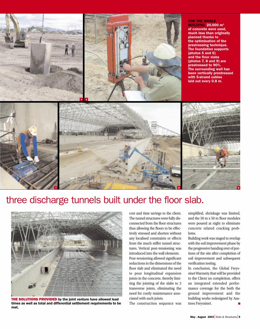
FOR THE WHOLE BUILDING, 20,000 m3
of concrete were used,much less than originallyplanned thanks to the optimisation of theprestressing technique.The foundation supports(photos 5 and 6) and the floor slabs (photos 7, 8 and 9) are prestressed to 90%. The surrounding wall hasbeen vertically prestressedwith 5-strand cables laid out every 0.8 m.
three discharge tunnels built under the floor slab.cost and time savings to the client.The tunnel structures were fully dis-connected from the floor structuresthus allowing the floors to be effec-tively stressed and shorten withoutany localised constraints or effectsfrom the much stiffer tunnel struc-tures. Vertical post-tensioning wasintroduced into the wall elements.Post-tensioning allowed significantreductions in the dimensions of thefloor slab and eliminated the needto pour longitudinal expansionjoints in the concrete, thereby limi-ting the jointing of the slabs to 3transverse joints, eliminating theneed for costly maintenance asso-ciated with such joints. The construction sequence was
simplified, shrinkage was limited,and the 50 m x 50 m floor moduleswere poured at night to eliminateconcrete related cracking prob-lems. Building work was staged to overlapwith the soil improvement phase bythe progressive handing over of por-tions of the site after completion ofsoil improvement and subsequentverification testing.In conclusion, the Global Freys-sinet Warranty that will be providedto the Client on completion, offersan integrated extended perfor-mance coverage for the both theground improvement and thebuilding works redesigned by Aus-tress Freyssinet. ■
THE SOLUTIONS PROVIDED by the joint venture have allowed leadtimes as well as total and differential settlement requirements to bemet.
4
7 8 9
3
May - August 2003 Soils & Structures 9

R E A L I Z A T I O N S
10 Soils & Structures May - August 2003
THE STATE LINE between Missouriand Illinois to the east of the
town of Cape Girardeau runs alongthe Mississippi river. It is crossed bya steel bridge that was put intoservice at the end of the 1920s, ter-minating the ferry service acrossthe river. For many years, it wasthe only crossing point within the500 km distance between SaintLouis and Memphis, and eventoday it is the only crossing fromthe region to the neighboring state,the closest neighboring bridgesbeing 55 km upstream in Chester,and 65 km downstream at CairoJunction.This structure is crucial for localexchanges, and it has been con-demned to be closed shortly: itswidth (twice 3.35 m) is increasinglyunsuitable for the continuouslyincreasing traffic needs (average17,000 vehicles per day) and in par-ticular increases the risks of acci-dents between heavy goods vehicles.This situation has led the MissouriDepartment of Transportation(Modot) to initiate constructionwork of a bridge that can carry adaily traffic of 26,000 vehicles, theestimated traffic volume for 2015.Construction work was interruptedfor four years as a result of founda-tion problems, and the site thenstarted again in 2000 after comple-tion of soil consolidation under the
control of a new main contractor,TBI (Taylor Brother Inc.). Theauthorities have already decided toname the future bridge after BillEmerson, in memory of the Sena-tor for Missouri in the AmericanCongress who died in 1996, andhad adopted a firm position infavor of this project.
Composite steel-concrete deck
The Bill Emerson bridge is a con-ventional design symmetrical aboutits center, consisting of a cablestayed structure with two 100 m talldouble H towers and a total lengthof 636 m, two 143 m side spans anda 350 m central span. It is 31.5 mwide, and carries twice two 3.65 mtraffic lanes and two 3 m wideemergency stop shoulders. On theeast side, in Illinois, the bridge isaccessed from a viaduct with eleven52 m long spans.The bridge deck is a steel and con-crete composite structure. Its lowerpart comprises 27 pre-assembledsteel elements, its total weight is1815 t, and the top slab is composedof 116 precast concrete slabs eachweighing 45 t. The deck is pre-stressed using 35 mm diameter bars,and is supported by type 19, 31, 37and 54C15 stay cables distributed intwo layers, the longest of which is180 m.
Freyssinet will need to supply almost750 t of sheated and greased strandsto build this structure. All stay cablesare injected with cement grout.Apart from the supply of materialsand equipment for the stay cablesand technical assistance, Freyssinetis also involved in the supply of prestressing for the towers, to beinstalled adjacent to the diaphr-agms using fourteen 19C15 cables(20.5 t), and in the stay anchor areausing 256 cables varying from 4C15to 13C15 (35.4 t).When the Bill Emerson bridge willbe completed at the end of 2003, thethousand lights of its 140 lamppostswill be reflected in the water of OldMan River. ■
A new crossingover theMississippiFreyssinet is supplying theprestressing for the towers and
stay cables of the largestbridge ever built in the State of Missouri, USA.
STRUCTURES/CAPE GIRARDEAU BRIDGE
Client: Missouri Departmentof Transportation.
Engineer: HNTB.General Contractor: TBI.Specialised contractor:
(supply of stay cables and prestressing, technicalassistance): Freyssinet.
▼▼
▼▼
PARTICIPANTS

REALIZATIONS
May - August 2003 Soils & Structures 11
DESIGNED FOR RESISTING AN 8 FORCE EARTHQUAKEon the Richter scale, parasismic dampers were installed between the pylons and the deck and specialdevices at each pier to absorb rotating and translation movements. To overcome vibrations of the 128 stay cables,all cables are fitted with needles (eight per layer).

R E A L I Z A T I O N S
12 Soils & Structures May - August 2003
Each cladding panel was made inFrance in an associated factory ofTerre Armée SNC, where specialcare was taken with quality of theconcrete required to resist aggres-sion due to frost and deicing salts.Reinforced Earth was also selectedfor the Périgueux East - PérigueuxWest section, but in this case for the‘composite abutments’ for twobridges now under construction. Inthese structures, the load carrying
Reinforced Earth improvements in Périgord
SOILS/A89 MOTORWAY
function was dissociated from theretaining function performed by theReinforced Earth structure, sincethe nature of the foundation soilmeans that large post constructionsettlements are expected. Thereforeeach abutment header beam isfounded on 0.80 m diameter boredpiles protected from foundationmovements by 1.10 m diameterconcrete shells.The aesthetics of these abutments
are largely due to the ease of place-ment of the panels and the flexibil-ity that they offer. The entire struc-tures represent 120,000 m2 of wallsurface area. Terre Armée SNC is responsible forall general stability studies of thereinforced foundations for this proj-ect, in addition to its normal serv-ices (the supply of cladding andreinforcement, design and techni-cal assistance). ■
The flexibility of use of ReinforcedEarth was one of the reasons why this technique was chosen for two work packages on the
future Clermont-Ferrand-Bordeaux motorwayunder construction near Périgueux, France.
FIVE ROAD RETAINING WALLS withheights of up to 18.30 m have to
be built on the segment of the A89motorway between Mussidan andPérigueux in Dordogne, France.The Reinforced Earth techniquewas the ideal solution for thesewalls, due to the ease with which itcan be blended into the environ-ment, and its capacity for adapta-tion to the constraints of alternat-ing rock and compressible terrain.
STRUCTURES/ONGA VIADUCT
Strengthening of the deck
THE 636 M LONG ONGA RAILWAY
viaduct in the Fukuoka region(Japan) of western Kyushu Islandwas opened to traffic in 1974. Itcomprises 37 spans of strength-ened concrete T-girders. After the
major Hanshin earthquake in 1995,the client, the Province ofKitakyushu Roads Departmentunder the authority of the Ministryof Development and Transport,strengthened the bridge piers using
steel plates. This strengthening wasfound to be insufficient, and a newcampaign to strengthen the bridgewas initiated.Following the call for bids, a trussstrengthening solution proposedby FKK was chosen to make theviaduct satisfy seismic standards.This process was to strengthen thebridge with lightweight trussesforming a simple structure, whichwould not have been possibleusing techniques such as steel orcarbon fiber lining of the bridgeelements. Furthermore, the cost ofthis solution for strengthening thestructure and improving the seis-mic performances of the viaductwas 40 to 50% lower than the costof conventional methods. Theprocess is easy to implement anddoes not require the use of anyheavy construction machinery.The system comprises 18 m longtrusses made of 40 cm diameter,1.2 cm thick steel tubes, on whichthe deck is supported through a
PARTICIPANTS
rubber support acting as a slidingbearing. In an earthquake, the slid-ing bearing isolates the bridge andlateral forces applied to the deck aredistributed through the strengthen-ing structures.Loads are applied to the trusses byinjecting an epoxy resin in three flatjacks, one located at the high pointof each arch and the two others atthe arch springings. The arch keythen provides a new bearing pointfor the deck. ■
Client: Province of KitakyushuRoads Department, under theauthority of the Ministry ofDevelopment and Transport.
Consultant: ChiyodaEngineering Consultants Co., Ltd.
Main Contractor: OshimaShipbuilding Co., Ltd.
Specialised contractor(flat jacks and engineeringmanagement): FKK Kyokuto Kogen Concrete Shinko Co., Ltd.
▼▼
▼▼
REALIZATIONS
May - August 2003 Soils & Structures 13
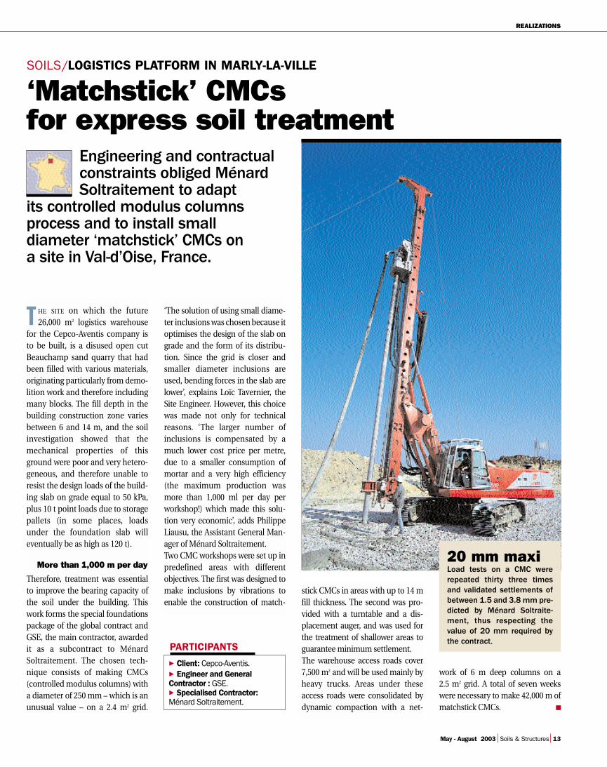
T HE SITE on which the future26,000 m2 logistics warehouse
for the Cepco-Aventis company isto be built, is a disused open cutBeauchamp sand quarry that hadbeen filled with various materials,originating particularly from demo-lition work and therefore includingmany blocks. The fill depth in thebuilding construction zone variesbetween 6 and 14 m, and the soilinvestigation showed that themechanical properties of thisground were poor and very hetero-geneous, and therefore unable toresist the design loads of the build-ing slab on grade equal to 50 kPa,plus 10 t point loads due to storagepallets (in some places, loadsunder the foundation slab willeventually be as high as 120 t).
More than 1,000 m per day
Therefore, treatment was essentialto improve the bearing capacity ofthe soil under the building. Thiswork forms the special foundationspackage of the global contract andGSE, the main contractor, awardedit as a subcontract to MénardSoltraitement. The chosen tech-nique consists of making CMCs(controlled modulus columns) witha diameter of 250 mm – which is anunusual value – on a 2.4 m2 grid.
‘The solution of using small diame-ter inclusions was chosen because itoptimises the design of the slab ongrade and the form of its distribu-tion. Since the grid is closer andsmaller diameter inclusions areused, bending forces in the slab arelower’, explains Loïc Tavernier, theSite Engineer. However, this choicewas made not only for technicalreasons. ‘The larger number ofinclusions is compensated by amuch lower cost price per metre,due to a smaller consumption ofmortar and a very high efficiency(the maximum production wasmore than 1,000 ml per day perworkshop!) which made this solu-tion very economic’, adds PhilippeLiausu, the Assistant General Man-ager of Ménard Soltraitement.Two CMC workshops were set up inpredefined areas with differentobjectives. The first was designed tomake inclusions by vibrations toenable the construction of match-
stick CMCs in areas with up to 14 mfill thickness. The second was pro-vided with a turntable and a dis-placement auger, and was used forthe treatment of shallower areas toguarantee minimum settlement.The warehouse access roads cover7,500 m2 and will be used mainly byheavy trucks. Areas under theseaccess roads were consolidated bydynamic compaction with a net-
Engineering and contractualconstraints obliged MénardSoltraitement to adapt
its controlled modulus columnsprocess and to install small diameter ‘matchstick’ CMCs on a site in Val-d’Oise, France.
SOILS/LOGISTICS PLATFORM IN MARLY-LA-VILLE
Client: Cepco-Aventis.Engineer and General
Contractor : GSE.Specialised Contractor:
Ménard Soltraitement.
▼▼
▼
PARTICIPANTS
Chaque colonne faitl’objet d’une feuille de
qualité recensant lesparamètres de forage
(couple de rotation,profondeur, vitesse) et
de bétonnage (pressionde pompage, débit,
volume de mortier etprofil de la colonne).
work of 6 m deep columns on a2.5 m2 grid. A total of seven weekswere necessary to make 42,000 m ofmatchstick CMCs. ■
‘Matchstick’ CMCs for express soil treatment
20 mm maxiLoad tests on a CMC wererepeated thirty three timesand validated settlements ofbetween 1.5 and 3.8 mm pre-dicted by Ménard Soltraite-ment, thus respecting thevalue of 20 mm required bythe contract.

R E A L I Z A T I O N S
14 Soils & Structures May - August 2003
STRUCTURES/BELLEVUE BRIDGE
Over the bridge and under the flyover
Innovative constructionmethods frequently make a
conventional site innovative. This isthe case for Bellevue bridge inNantes, where the Freyssinet-Dodinjoint venture has successfullycontinued its road widening work inthe presence of road traffic.
65,000 VEHICLES, including 10% ofheavy good vehicles, use the
single lane between the south andeast ring roads in the Nantes area(France), every day. Bellevue bridgeover the Loire is an unavoidable andparticularly sensitive point alongthis road and is the site of severerush hour congestion, which is whythe Loire- Atlantique GeneralCouncil decided to widen thebridge. This work is now underconstruction and will contribute to
improving traffic fluidity and main-taining continuity of the two dualcarriageways on Nantes ring roadincluding the construction of inter-changes on each side of the bridge.
15 months work
Bellevue bridge is composed of twoparallel and independent decks,one called the downstream deckbeing 370 m long and 10.5 m widecarrying the inner ring road andthe upstream deck being 385 m
long, 15.2 m wide and 22 cm thickslabs weighing 300 t each will becast in situ on the existing deck.Almost 15 thousand 3.6 cm diame-ter holes were drilled in the top slabfor fitting connectors that will fixthe new slab to the existing bridge.On the upstream side, a formworksystem is used for widening thedeck. The group will install pre-stressing cables in the box beam, toresist loads from the new slab. Thework will also include the replace-
long and 12 m wide carrying theouter ring road. The work began onthe upstream structure and con-sisted of widening the 3.20 m deckfirstly to widen the road itself (hardshoulder), and secondly to addpedestrian and cyclist tracks thatcan be used to cross the Loire incomplete safety. The work on theupstream deck will last for 10months and the work on the down-stream deck for 5 months.On the upstream deck, eleven 37 m

REALIZATIONS
May - August 2003 Soils & Structures 15
Client:Ministry of Development, Transport and Housing.
Engineer:Loire-Atlantique DevelopmentAuthority.
General Contractor:Freyssinet-Dodin joint venture.
▼▼
▼
PARTICIPANTS
ment of bearings and expansionjoints. However, an innovative con-struction method had to be used toreconcile strengthening and con-creting work with the heavy traffic.Thus, the group installed a 90 mlong, 7 m wide temporary flyoveron the deck weighing 160 t, thatcovers the site as work progressesand over which vehicles pass strad-dling the work area; a first inFrance. Obviously, this solutionrequires that very strict safety rulesare respected, and the speed is lim-ited to 30 km/h for cars. The largestoperations take place during theweek-end to minimize distur-bances, and traffic is not inter-rupted at any time.
A tricky operation
Every Friday evening at 20h00, thebridge on which the work is beingdone is closed to vehicular traffic,and all the traffic is changed over tothe other deck where it is carried byone lane in each direction. The fly-over moving operation starts at10h00 pm, and is a difficult opera-tion due to its size. Saturday morn-ing is spent concreting areas thathad been strengthened the previ-ous week-end using a mobile trav-eler protected by the flyover; at thesame time, the next segment isstrengthened using a crane. Theflyover is then moved above thestrengthened area. After one day ofcuring (Sunday) the concrete hasbecome strong enough to carrytraffic again on Monday morningat 7h. ■
STRUCTURES/ZERI VIADUCT
530 t suspendedFreyssinet Italy has designedand built an innovative span liftingsystem on a repair site on the Italian Zeri motorway viaductbetween Parma and La Spezia.
ZERI VIADUCT was built in the early1960s and is composed of two
385 m parallel decks. There areeleven spans in each deck, eachspan is 35 m long and weighs 530 t,and is composed of four precastbeams supported on pier heads anda cast in situ reinforced concreteslab. The maximum height of thepiers is about 40 m.The global contract applies to reno-vation of the viaduct, and the partsubcontracted to Freyssinet Italy byLicis SPA covers lifting of the 22viaduct spans, which is necessary toreplace the neoprene bearings,install the seismic devices and to dothe work to strengthen the pierheads. Vincenzo Emprin, FreyssinetItaly’s Business Manager, explains:‘The configuration of the piers and
the use of longitudinal strenghten-ing prestressing at the heads oblig-ed us to lift the deck by 2 m to allowroom for the tensioning jacks topass through. This is why Ange Pon-tier from Freyssinet Italy’s Engineer-ing Department specially devel-oped a metallic structure for liftingfrom above’.
Sixteen 60 t jacks
This system, which is capable oflifting spans individually, is sup-ported directly on pier heads usingfive steel columns located at theends of the span. The lifting bars,with continuous threads (36 mmdiameter) are inserted through the100 mm openings drilled in theslab. Retaining bars are fixed toadjacent spans that act as counter-
weights, to avoid the constructionof a heavy lifting structure whichwould therefore be difficult tomove.The actual lifting operation is doneby sixteen 60 t jacks with a traveldistance of 25 cm controlled by acomputer aided control center.When lifting is complete, the metal-lic structure fitted with specialrollers is moved and the openingsare reclosed with reoplastic con-crete. ‘This means of displacementsaves the cost of a crane, and alsomeans that the lifting bars andhydraulic systems can be left inplace without needing to systemati-cally disassemble and reassemble,which represents a considerabletime saving’ says Vincenzo Emprin.This is an undoubted advantagesince the motorway is to be openedfor traffic in the Summer. ■
Client: A15 Autocamionale della Cisa.
General contractor: Licis SPA.Specialised contractor:
Freyssinet Italy.Design office (structure):
A15 Autocamionale della Cisa.Design office (lifting):
Freyssinet Italy.▼
▼▼
▼▼
PARTICIPANTS
R E A L I Z A T I O N S
16 Soils & Structures May - August 2003
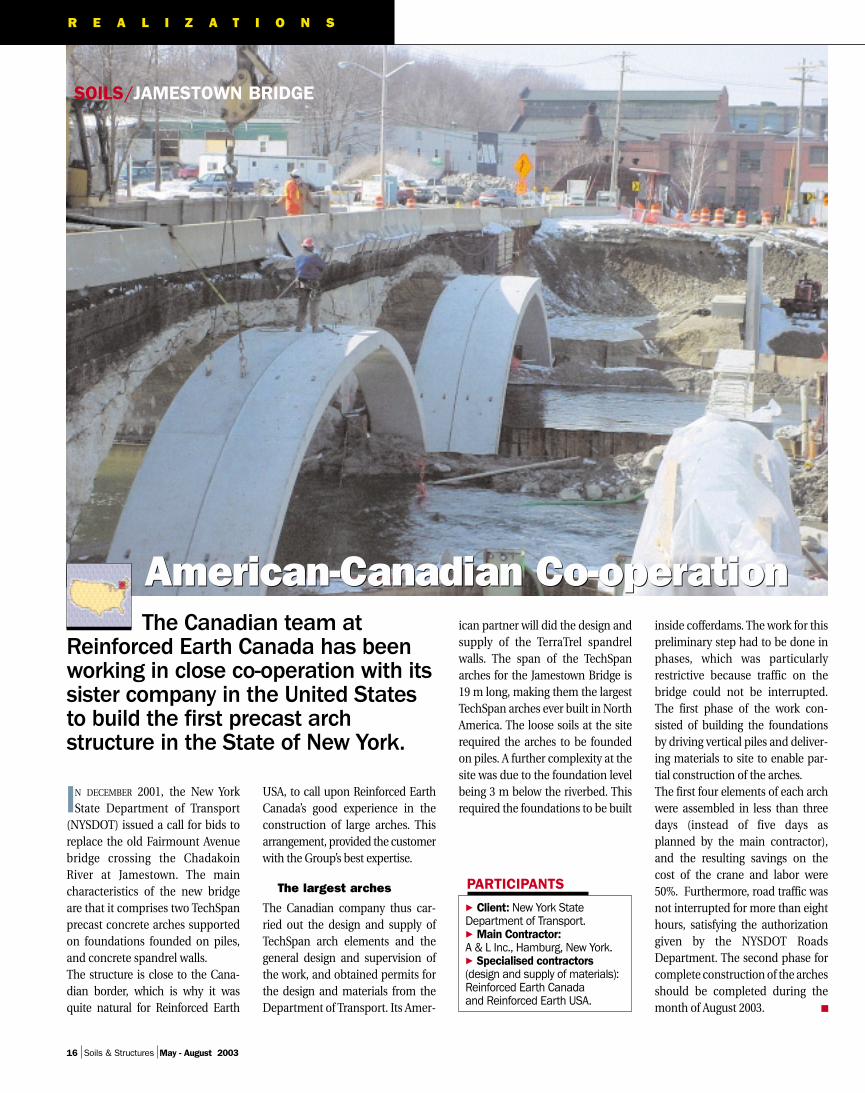
SOILS/JAMESTOWN BRIDGE
American-Canadian Co-operationThe Canadian team at
Reinforced Earth Canada has beenworking in close co-operation with itssister company in the United Statesto build the first precast archstructure in the State of New York.
IN DECEMBER 2001, the New YorkState Department of Transport
(NYSDOT) issued a call for bids toreplace the old Fairmount Avenuebridge crossing the ChadakoinRiver at Jamestown. The maincharacteristics of the new bridgeare that it comprises two TechSpanprecast concrete arches supportedon foundations founded on piles,and concrete spandrel walls.The structure is close to the Cana-dian border, which is why it wasquite natural for Reinforced Earth
USA, to call upon Reinforced EarthCanada’s good experience in theconstruction of large arches. Thisarrangement, provided the customerwith the Group’s best expertise.
The largest arches
The Canadian company thus car-ried out the design and supply ofTechSpan arch elements and thegeneral design and supervision ofthe work, and obtained permits forthe design and materials from theDepartment of Transport. Its Amer-
ican partner will did the design andsupply of the TerraTrel spandrelwalls. The span of the TechSpanarches for the Jamestown Bridge is19 m long, making them the largestTechSpan arches ever built in NorthAmerica. The loose soils at the siterequired the arches to be foundedon piles. A further complexity at thesite was due to the foundation levelbeing 3 m below the riverbed. Thisrequired the foundations to be built
inside cofferdams. The work for thispreliminary step had to be done inphases, which was particularlyrestrictive because traffic on thebridge could not be interrupted.The first phase of the work con-sisted of building the foundationsby driving vertical piles and deliver-ing materials to site to enable par-tial construction of the arches.The first four elements of each archwere assembled in less than threedays (instead of five days asplanned by the main contractor),and the resulting savings on thecost of the crane and labor were50%. Furthermore, road traffic wasnot interrupted for more than eighthours, satisfying the authorizationgiven by the NYSDOT RoadsDepartment. The second phase forcomplete construction of the archesshould be completed during themonth of August 2003. ■
Client: New York StateDepartment of Transport.
Main Contractor:A & L Inc., Hamburg, New York.
Specialised contractors(design and supply of materials):Reinforced Earth Canada and Reinforced Earth USA.
▼▼
▼
PARTICIPANTS
American-Canadian Co-operation

REALISATIONS
May - August 2003 Soils & Structures 17
STRUCTURES/DUBAI TOWERS
Prestressed concretefloors for two structures
THE CAPRICORN AND AL JABER Com-plex (Shangri-la Hotel) towers
have both be built in Sheikh ZayedRoad in Dubai, and both buildingprojects are among the mostremarkable in the United ArabEmirates due to their architectureand their height.Freyssinet Gulf worked in co-oper-ation with the Clients Representa-tives to refine the structural aspectof the projects. Many concretebuildings in Dubai are being stud-ied for alternate prestressing solu-tions which reduced the thicknessof the floors and core spaces,reduces the number of load bear-ing columns (and therefore opti-mises the layout of the internalspace), and finally reduces workconstruction times.
A suspended mezzanine
There are forty-seven storeys in theCapricorn tower. The solutionadopted for floor slabs uses a com-pact prestressing system composedof flat anchors with four 12.9 mmsteel strands grouted after tension-ing. Car park floors were also pre-stressed (a total of 260 t of steel wasinstalled on the structure). The carpark was converted by Freyssinet toa post-tensioned structure.The Al Jaber Complex buildingcomprises two parallel towers and itis now the soon to open Shangri-laHotel. Its maximum height is 196 mand it comprises 43 floors and 2basement levels. Its original design necessitatedthe construction of post-tensionedload transfer beams on five levelsthroughout the twin towers.
Six majoradvantages
Lower concrete and rebarquantities.Thin slabs.Easy to install services andnetworks under the ceilingwhere flat slabs are used.Reduction in the numberof load bearing columns.Increase in the width of openings and trafficspaces (for car parks).Resistance to earthquakes.▼
▼▼
▼▼
▼
Freyssinet Gulf installed 250 t ofprestressing steel in total using the12K15, 19K15 and 27K15 systems.The 4th floor was used to suspendthe mezzanine and lower floorswith vertical post-tensioning.A prestressed beam solution to support the floors, proposed byFreyssinet Gulf to the client, wasalso selected for the adjacent nine-storey car park building. ■
PARTICIPANTS
Prestressing concrete floors provide many opportunities for designers. Illustration
Capricorn Tower.
Al Jaber Complex Tower.
Capricorn TowerClient: Ahmed Siddique
and Sons.Engineer: Schuster Pechtold
& Partner.Design Office: Dubai
Contracting Company.Specialised Contractor:
Freyssinet Gulf.
Al Jaber Complex TowerClient: Obaid Al Jaber.Engineer: Al Habtoor Murray
and Roberts.Design Office: Norr Group.Specialised Contractor:
Freyssinet Gulf.
▼▼
▼▼
▼▼
▼▼

18 Soils & Structures May - August 2003
One of theadvantages
of this processthat was
awarded thebronze medal in
the innovationcompetition
organised by theEgis company, isthat it simplifies
the design oftowers.
The direction control saddles tech-nique borrowed from suspensionbridges has often been used inthe past, particularly with closedcables, to change the direction of aload bearing cable at the crossingover towers. This type of devicehas also been used for stay cablebridges to make cables continuousat the tower crossing. This was thecase for Brotonne and Aradebridges.The arrangement of the passageusing a saddle simplifies the towerdesign. It is attractive structurally,but it does create a singular point inthe cable which in the past made it
difficult to satisfy the requirementsof a stay cable. Forces at the saddle are transferredover a certain length of the ‘typical’part of the stay cable that is notdesigned for this purpose, and thecurvature reduces the resistance tofatigue and the ultimate strength ofthe cable.
A solution adaptedto the Cohestrand strand
Furthermore, the creation of a fixedpoint absorbing asymmetric forcesis often incompatible with long lifeof the cable and the possibility ofreplacing it.
Awards for the multitube stay
T R A N S V E R S E

TRANSVERSE
May - August 2003 Soils & Structures 19
cable saddleFreyssinet International & Cie pro-posed a new saddle design to sat-isfy the specification for the SungaiMuar bridge, Malaysia, writtenby Jean Muller International. Thisdesign is capable of overcomingthese disadvantages and guaran-tees long life. The ‘multitube saddle’ based onuse of the Cohestrand patentedstrand, was then developed jointlyby Jean Muller International (GuyFrémont) and Freyssinet Interna-tional & Cie (Jean-Claude Perche-ron).With this system, the strands areindividually deviated, which elimi-
nates wear problems. The multi-tube saddle thus offers excellentfatigue performance with stressvariations of more than 200 MPa,and provides continuity of anti-corrosion protection of strands andenables individual disassembly. Ithas been tested and validated byfatigue and friction tests.Specific installation methods weredefined for the site and the strandby strand installation of the staycables. The work began in March 2003 andis continuing at a sustained rate. ■
COMPOSITION• A group of individual aluminum
tubes bent to a radius of between2.5 and 4 m.
• An outer steel tube (with a diameterfrom 300 to 500 mm).
• An HDPE (high density polyethylene)‘plug’ at each end.
• Ultra-high performance concrete,injected between the individualtubes and the outer steel tube.
PROPERTIES• Blocking by friction of asymmetric
loads transmitted to the tower equal to 20% Frg (guaranteed ultimate strength) at the failure limit state.
• Resistance to fatigue exactly the same as the stay cable.
• Filtration of cable direction changesat the entry into the saddle.
• Continuity of anti-corrosion barriers.• Possibility of replacing stay cables
strand by strand.
ADVANTAGES• Aesthetic: additional
freedom offered to architects for the tower design.
• Cost savings.• Ease of replacing strands.• No maintenance.• Flexibility of construction
(no cement grout to be injected on site).
• Long life due to exceptional fatiguestrength and corrosion resistance.
TRADE FAIR
Freyssinet booth at TPTech
Five months afterparticipating in the fibconference in Osaka,the Freyssinet Groupattended the TPTech tradefair, which was held for thesecond time at the Cnit, Paris-la-Défense, betweenMarch 11 and 13 2003. This trade fair is a majorinterface between differenttechnologies and animportant meeting place for French public works and civil engineeringprofessionals, and it offered a unique opportunity for Freyssinet to present its activities in the soils and structures activities. The group also took an active part in the TPTechconference, particularlythrough presentations byBenoît Lecinq, FreyssinetEngineering Manager,on reinforcement of the piersfor A4 motorway overpasses,and Serge Varaksin, the Ménard SoltraitementExport Manager, on soilconsolidation in Hamburg. ■
Freyssinet booths at the fib (1)conference and TPTech (2)trade fair
The construction of a roadjunction leading to the palaceof the Sheikh of Abu Dhabiprovided an opportunity forFreyssinet Middle East toparticipate in theconstruction of a bridgeaccess ramp. The upper partsof bridge retaining walls aremade of Reinforced Earth®
with Freyssisol Soilreinforcement, while 1,700 m2
of the lower parts of the wallsare constructed using the innovative TerraBlocktechnique. This system,which is also a ReinforcedEarth® retaining process, iscomposed of prefabricatedhydraulically pressedconcrete hollow blocks andFreyssisol type reinforcingstrip of a specially developedgrade. It is a means of makingwalls with a variablegeometry, adapted to the useof all types of granular fill. In particular, the blockfabrication process and theirease of placement open upmany opportunities forarchitectural solutions. By theend of this contract, 32,000 m2 of TerraBlock wallswere on order for similarprojects throughout thecapital of the Emirate. ■
ARCHITECTURE
TerraBlock andthe urban environment
Palm trees and flowerbeds will be planted on the terracesof this structure.
Mutation of a traditionalprocess
1
2


![Development Length of Prestressing Strands [PCI]](https://img.dokumen.tips/doc/110x75/55cf9c67550346d033a9b95b/development-length-of-prestressing-strands-pci.jpg)


![[Type the document title] · 3. Define circular prestressing. (AUC Nov/Dec 2011, 2012, 2013, 2010) When the prestressed members are curved in the direction of prestressing, the prestressing](https://img.dokumen.tips/doc/110x75/606c280e14270236063ac6f6/type-the-document-title-3-define-circular-prestressing-auc-novdec-2011-2012.jpg)