Embed Size (px)
Citation preview

Presented at the 37th European PV Solar Energy Conference and Exhibition, 7-11 September 2020
1
INTEGRATED LIGHTWEIGHT, GLASS-FREE PV MODULE TECHNOLOGY FOR BOX BODIES OF
COMMERCIAL TRUCKS
Christoph Kutter1, Felix Basler1, Luis Eduardo Alanis1, Jochen Markert1, Martin Heinrich1, Dirk Holger Neuhaus1
1 Fraunhofer Institute for Solar Energy Systems ISE, Heidenhofstrasse 2, 79110 Freiburg, Germany
Corresponding author: Christoph Kutter | Phone: +49 (0)761 4588 2196 | e-mail: [email protected]
ABSTRACT: We propose a new integrated photovoltaic module technology and manufacturing process for the
seamless integration into box body roofs of commercial trucks to unlock a 90.2 GW potential in the EU. Our
approach is to laminate c-Si photovoltaic cells with an ETFE-top cover onto conventional GFRP-hard-foam sandwich
elements, which can be directly installed with conventional box body profiles. We find that VIPV modules must be
lead-free and report results of Hot-Spot, Wet-leakage test and insulation tests to prove the electrical safety of the new
concept. We perform UV, DH and accelerated TC testing on minimodules and find a mean PMPP drop of 3.6% for
PERC, ribbon soldered half-cell modules after accelerated TC200 due to finger failure and partial ribbon
disconnections. We conclude that conventional soldered ribbon based interconnection in combination with polymer
based cover materials lead to unfavorable thermomechanical stresses in TC. We propose the usage of interconnection
technologies that are less sensitive to thermomechanical stresses like Multiwire or shingling as we find that the mean
drop in PMPP of shingle modules to be 1%. PERC Solar cells encapsulated using the proposed module design remain
stable after DH1000 and UV 60 kWh/m². We equipped a Mega electronics e-Worker with a photovoltaic active box
body featuring the first generation of proposed module technology and reported initial monitoring results after 10
months of outdoor operation.
Keywords: VIPV, Vehicle integrated photovoltaics, trucks, lightweight, glass-free, PV module, ETFE
1 INTRODUCTION
Vehicle-Integrated Photovoltaic (VIPV) in general is
a promising solution to reduce primary energy
consumption and carbon emissions in the mobility
sector.[1] Measurement studies conducted by Fraunhofer
ISE on moving 40t-trucks in central Europe and the
greater New York area reveal that a DC-yield of 5,300
and 7,395 kWh/a per truck can be generated with 18 %
efficiency module technology. [2] Assuming an
electricity demand of 125 kW per 100 km e.g. of the
announced Tesla Semi [3] and a yearly driving distance
of 95,389 km (German average for a tractor unit [4]), at
least 4.4% for the greater New York area and 6.2 % for
central Europe of the yearly energy demand could be
covered by the integrated PV system.
More than 39.7 Million light, medium and heavy duty
vehicles (6,6 Million > 3.5 t) were operated in the EU in
2019 [5]. Based on 2018 German vehicle licensing data,
heavy duty vehicles (> 3,5 t) hold an estimated average
roof surface area of 21.5 m² [6]. This constitutes a
technical VIPV potential (21 % efficiency, 95 % usable
roof area) for commercial vehicles of more than 90.2 GW
for the EU (Germany, 8 GW).
With a share of 26.3 %, trucks’ and buses’
contribution to road transport related EU green-house gas
emissions in 2017 accounted for ~180 MtCO2e [7]. As a
result, a yearly CO2 saving potential of 11.5 MtCO2e can
be estimated by the utilization of solar energy through
VIPV on commercial vehicles in the EU. In order to
unlock this potential we propose a lightweight, glass-free
module technology. The presented module technology
allows for a resource and cost efficient integration of PV
into box bodies. The solar active body panels are
compatible with conventional box body structures
enabling an easy implementation of the innovative
technology providing a path for PV-applications in
commercial vehicles.
2 MODULE TECHNOLOGY
2.1 New requirements for VIPV Modules
The safety and functionality related requirements
towards automotive integrated photovoltaic modules arise
from the established PV standards as well as standards
from automotive frameworks. Selected standards and
regulations are mentioned below.
VIPV Modules are photovoltaic modules and
therefore need to meet the safety requirements according
safety to IEC 61730.
DIRECTIVE 2011/65/EU on the restriction of the use
of certain hazardous substances in electrical and
electronic equipment defines an exception for
“photovoltaic panels intended to be used […] at a defined
location”. Road-mobile PV-panels therefore are not
covered by that exception and conclusively need to be
lead-free. [8]
Regulation ECE-R100, which addresses provisions
concerning the approval of vehicles with regard to
specific electric power train requirements, defines a ‘high
voltage level’ (> 60 VDC) that requires additional safety
measures e.g. insulation resistance monitoring and
voltage drop rates after opening of connectors. [9]
In consequence when multiple modules are connected
in series, with a system voltage that exceeds 60 VDC,
additional safety measures need to be implemented to
guarantee that the voltage drops below 60 VDC within 1 s
after connectors are opened or cables or modules are
damaged.
2.2 Module Concept and Approach
The glass-free module technology is based on
conventional hard-foam box body panels. [10] The box
body panel used in this study is made up of two glass-
fiber reinforced plates that encompass a hard-foam core.
Due to the tensile strength of the glass fibers the structure
is extremely rigid and torsion-resistant. Glass is not
technically feasible as a top cover for VIPV modules, as
area specific weight is too high and rupture safety in case

Presented at the 37th European PV Solar Energy Conference and Exhibition, 7-11 September 2020
2
of an accident or torsion of the box body is not
guaranteed. Hence we use weather resistant ETFE foil as
a front cover as illustrated in Figure 1.
Figure 1: Schematic cross section of the box body
module technology
Junction Boxes and Cables are embedded in the hard
foam core of the sandwich element. The additional
weight by integrating the PV-functionality to
conventional sandwich elements is minimal with
< 1.4 kg/m².
2.3 Manufacturing process
The automated soldering interconnection of half cut
Passive Emitter Rear Cells (PERC) was performed with a
Teamtechnik TT1800. The shingling interconnection of
1/5 PERC shingled cells was done using a Teamtechnik
TT1600 ECA. [11]
For lamination we used a Bürkle E-LAPV Laminator
with a bottom heating plate (bottom) and an optional
heating capable membrane (top). Due to the flexible
elastic front cover foil a sunny side up lamination
approach would be beneficial. However, the foam core of
the body panel acts as a heat insulator. Therefore, the
heat transfer from the heating plate through the sandwich
element in a sunny-side-up lamination approach is very
limited and the heat flow through the membrane is not
sufficient to reach the required temperature for the
encapsulant to crosslink. In order to manufacture these
panels in a conventional PV-Laminator at Fraunhofer
ISE’s laboratory ModuleTec, we developed a sunny-side
down lamination process where the module layup is done
on a heat conductive carrier. The whole setup is moved
into the laminator and processed at 160°C for 10 mins.
The process is applicable in conventional industrial
laminators.
2.4 Module format for box bodies in commercial vehicles
Within the European Union the width of commercial
transportation vehicles is regulated. The directive
EU 2015/719 and national road traffic regulations define
maximum vehicle dimensions. For utility vehicles and
therefore box bodies, the maximum width is 2.55 m.
Cooling trucks built of insulation walls with a thickness
> 45 mm must not be wider than 2.60 m. [12]
Based on the standardized vehicle dimensions we
suggest standardized module dimensions to be
2.50 x 1 m² as the structural integrity of the box body
benefits from continuous roof-panels across the
movement direction of the vehicle.
3 RELIABILITY TESTING
To prove the suitability and reliability of the
proposed module technology, selected Module Safety and
Module Quality Tests according to IEC 61730 and
IEC 61215 were performed on laminates featuring the
setup illustrated below (Figure 2).
Figure 2: Schematic material stack of the tested
laminates (ETFE – Ethylene tetrafluoroethylene, EVA –
Ethylene-vinyl acetate, GFRP – glass fiber reinforced
plastic)
Insulation Test (MQT 03), and Wet leakage current
test (MQT 15) were performed before and after a Hot-
spot endurance test (MQT 09) on a 60-full-cell-laminate,
(see Figure 3). The maximum cell temperature reached
during the Hot-Spot endurance test was 146 °C when cell
A8 was shaded 25 %.
No visual defects were found and the module passed
Wet leakage and insulation tests afterwards.
Figure 3: Photo of module after Hot-Spot endurance test,
with marked shaded cells. Infrared images of the
respective shaded cell and highest measured temperatures
during Hot-Spot endurance testing
Minimodules with PERC half cells and PERC shingle
strings were built and exposed to environmental testing.
The used GFRP material for the minimodules featured no
gelcoat layer.
Three half-cell modules have undergone UV-Testing
with cumulative dose of 15, 30 and 60 kWh/m². Four
half-cell modules have been exposed to 1,500 h Damp
heat testing in 500 h steps.
The accelerated thermal cycling (aTC) procedure
proposed by Schiller et al. with higher heating/cooling
rates (8 K/min) and a 25 min dwell time was applied on
four half-cell modules and four shingle modules [13].
After each testing step the modules have been I-V
and EL characterized at Fraunhofer ISE’s ModuleTEC.
The IV-measurements have been analytically
temperature-corrected to 25 °C. The used PERC cells
were not stabilized for Light induced degradation (LID)
[14] and light and elevated temperature induced
degradation (LETID) [15].
After aTC200 we found the half-cell laminates
mechanically intact and no delamination of the
encapsulation was observed. The GFRP exhibits minor
Presented at the 37th European PV Solar Energy Conference and Exhibition, 7-11 September 2020
3
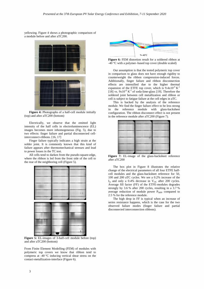
yellowing. Figure 4 shows a photographic comparison of
a module before and after aTC200.
Figure 4: Photographs of a half-cell module initially
(top) and after aTC200 (bottom)
Electrically, we observe that the emitted light
intensity of the half cells in electroluminescence (EL)
images becomes more inhomogeneous (Fig. 5), due to
two effects: finger failure and partial disconnected cell-
interconnect-ribbons. [16, 17]
Finger failure typically indicates a high strain at the
solder joint. It is commonly known that this kind of
failure appears after thermomechanical stresses and lead
to power losses in the TC test. All cells tend to darken from the pseudo-square-edge,
where the ribbon is led from the front side of the cell to
the rear of the neighboring cell (Figure 5).
Figure 5: EL-images of 3-half-cell module before (top)
and after aTC200 (bottom)
From Finite Element Modelling (FEM) of modules with
polymeric top covers we know that ribbon tend to
compress at -40 °C inducing vertical shear stress on the
contact-metallization-interface (Figure 6).
Figure 6: FEM distortion result for a soldered ribbon at
-40 °C with a polymer–based top cover (double scaled)
Our assumption is that the tested polymeric top cover
in comparison to glass does not have enough rigidity to
counterweight the ribbon compression-induced forces.
Additionally, finger failure and ribbon disconnection
effects are intensified due to the higher thermal
expansion of the ETFE top cover, which is 9.4x10⁻⁵ K-1
[18] vs. 9x10⁻⁶ K-1 of soda-lime-glass [19]. Therefore the
soldered joint between cell metallization and ribbon or
cell is subject to fatigue failure at the cell edges in aTC.
This is backed by the analysis of the reference
module. We find the finger failure effect to be less strong
in the reference module with glass-backsheet
configuration. The ribbon disconnect effect is not present
in the reference module after aTC200 (Figure 7).
Figure 7: EL-image of the glass-backsheet reference
after aTC200
The box plot in Figure 8 illustrates the relative
change of the electrical parameters of all four ETFE half-
cell modules and the glass-backsheet reference for 50,
100 and 200 aTC cycles. We see a 0.2% increase of the
Isc and only a 0.4% decrease in VOC after 200 cycles.
Average fill factor (FF) of the ETFE-modules degrades
strongly by 3.6 % after 200 cycles, resulting in a 3.7 %
average reduction of module power PMPP compared to
2.5 % for the reference module.
The high drop in FF is typical when an increase of
series resistance happens, which is the case for the two
observed failure modes (finger failure and partial
disconnected interconnection ribbons).
Presented at the 37th European PV Solar Energy Conference and Exhibition, 7-11 September 2020
4
Figure 8: Relative losses after aTC – aging of half-cell-
modules
The presented results indicate that for the proposed
ETFE-GFRP module technology interconnection
technologies that induce less mechanical stress, e.g.
shingled or multi-wire connection through smaller wire
diameters, might be beneficial for better TC performance.
Multiwire modules have been observed to show better
TC performance in other studies. [13]
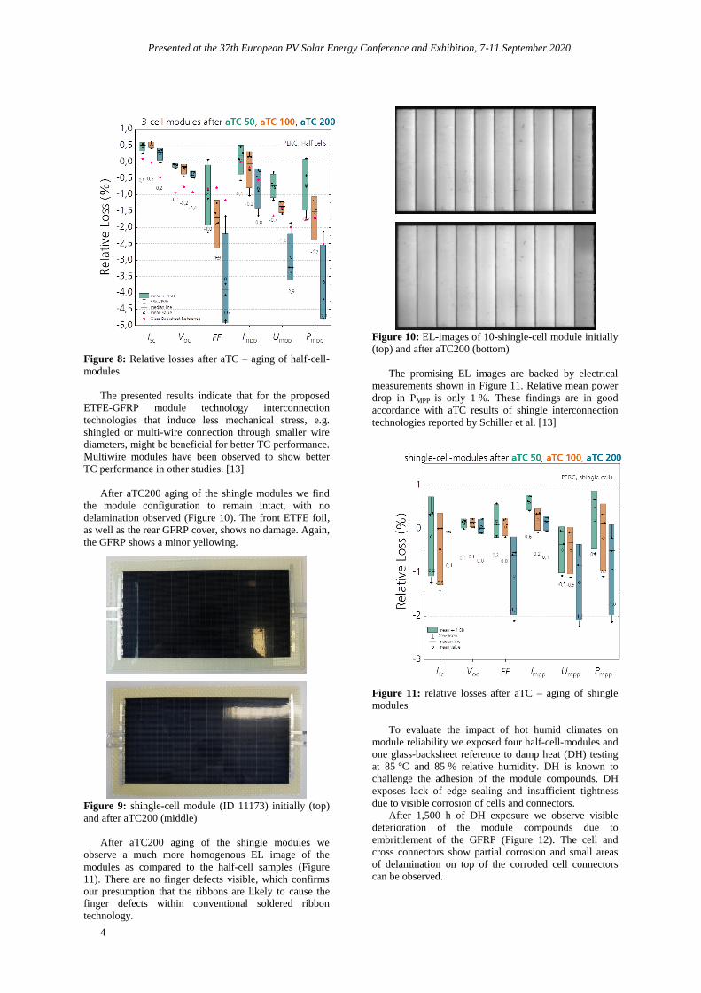
After aTC200 aging of the shingle modules we find
the module configuration to remain intact, with no
delamination observed (Figure 10). The front ETFE foil,
as well as the rear GFRP cover, shows no damage. Again,
the GFRP shows a minor yellowing.
Figure 9: shingle-cell module (ID 11173) initially (top)
and after aTC200 (middle)
After aTC200 aging of the shingle modules we
observe a much more homogenous EL image of the
modules as compared to the half-cell samples (Figure
11). There are no finger defects visible, which confirms
our presumption that the ribbons are likely to cause the
finger defects within conventional soldered ribbon
technology.
Figure 10: EL-images of 10-shingle-cell module initially
(top) and after aTC200 (bottom)
The promising EL images are backed by electrical
measurements shown in Figure 11. Relative mean power
drop in PMPP is only 1 %. These findings are in good
accordance with aTC results of shingle interconnection
technologies reported by Schiller et al. [13]
Figure 11: relative losses after aTC – aging of shingle
modules
To evaluate the impact of hot humid climates on
module reliability we exposed four half-cell-modules and
one glass-backsheet reference to damp heat (DH) testing
at 85 °C and 85 % relative humidity. DH is known to
challenge the adhesion of the module compounds. DH
exposes lack of edge sealing and insufficient tightness
due to visible corrosion of cells and connectors.
After 1,500 h of DH exposure we observe visible
deterioration of the module compounds due to
embrittlement of the GFRP (Figure 12). The cell and
cross connectors show partial corrosion and small areas
of delamination on top of the corroded cell connectors
can be observed.

Presented at the 37th European PV Solar Energy Conference and Exhibition, 7-11 September 2020
5
Figure 12: Half-cell module initially (left) and after
DH1,500 (right)
The EL images in Figure 13 after DH1,500 show
signs of corrosion at cell edges as well as the cell
connector edges.
Figure 13: EL-image of a half-cell module initially (left)
and after DH1500 (right)
We find similar deterioration effects after DH1500 in
the glass-backsheet-reference (Figure 14).
Figure 14: Photograph (left) and EL image (right) of
glass-backsheet reference after DH1500
Analyzing the mean relative losses of the electrical
module parameters in Figure 15, we observe a mean PMPP
change of -5 % after DH1500 (-2.5 % after DH1000),
which is -2.5 % more than the glass-backsheet reference
module.
We expect that the sandwich elements framed and
sealed within the box body (Figure 18) will see much less
exposure to humidity, therefore embrittlement of the
GFRP should be less relevant. Furthermore, applying a
gelcoat to the exposed surfaces of the GFRP is a well-
known approach to improve weather stability of GFRP
[21].
Figure 15: relative losses after DH – aging of half-cell-
modules
To determine the UV weathering resistance of the
glass-free module concepts, three half-cell modules were
conditioned with 15, 30 and 60 kWh/m² of UV light from
the front side according to MQT 10 of IEC61215.
Figure 16: Half-cell module initially (left) and after UV
60 kWh/m² (right)
Figure 17: Relative losses after UV-aging
We found no visible deterioration of the module
compounds after conditioning with 60 kWh/m² (Figure
16). Although by visual inspection and EL imaging no
damages could be identified, average module power
output drops by 2 % while FF slightly increases (Figure
-1,3
-1,6 -1,7
-0,7-0,6
-0,5
0,3
0,1 0,0
-0,9
-1,4 -1,4
-0,8 -0,8 -0,8
-1,8
-2,2
-2,0
Isc Voc FF Impp Umpp Pmpp
-3
-2
-1
0
1
Rela
tive
Lo
ss (
%)
mean +- 1SD
5%~95%
median line
mean value
2-cell-modules after UV 15, UV 30, UV 60
PERC, half cells

Presented at the 37th European PV Solar Energy Conference and Exhibition, 7-11 September 2020
6
17). This is only possible since Isc drops quite
significantly by 1.7 %. A possible reason could be
degradation within the EVA encapsulant resulting in
increased absorption or reflection within the EVA layer.
Further validation experiments to identify the degradation
mechanisms are planned.
4 OUTDOOR EXPOSURE - DEMOTRUCK
In fall 2019 a Mega electronics e-Worker was
equipped with a vehicle integrated PV box body by TFS
Fahrzeugbau GmbH in Umkirch, Germany. The modules
are embedded and installed via conventional aluminum
box body frames and additionally sealed with silicon
sealants. The sides of the box body can be orientated to
the sun (Figure 18).
The first module generation, featuring shingled solar
cells and initial interconnection technology based on
Electrically Conductive Adhesives (ECA) were
developed at Fraunhofer ISE’s ModuleTEC. [11] The 6
modules, installed on the sides and roof (Figure 18),
achieve a peak power of 990 W and are connected to the
drive train battery via a DC-DC-Converter. The vehicle is
in daily outdoor operation at Fraunhofer ISE’s campus in
Freiburg, Germany.
The truck is monthly monitored by visual inspection
and every half year the modules are tested using EL
imaging to detect any ageing effects. During the 10
months of outdoor exposure (September 19 – July 20),
the modules have experienced different environmental
loads such as high irradiation at elevated ambient
temperatures, snow, rain, heat and soiling (Figure 19).
Figure 18: Fraunhofer ISEs Mega electronics e-
worker with PV-box body
It was found that the module setup withstands the
observed conditions robustly. After 10 months of
operation no delamination is observed, the cover foils
remain intact.
(a)
(b)
(c)
(d)
Figure 19: Environmental loads: High irradiation at
ambient temperatures of >35°C during summer 2020 (a);
soiling due to pollen during spring 2020 (b): rain (c) and
snow cover during winter 2020 (d)
Further minor damages have been found where an
external mechanical force was certainly at play (Figure
20).
Figure 20: Scratch on the surface of the ETFE foil (left)
damaged cells in the EL image (right)
With the EL imaging we find that the emitted
radiation levels of the shingled solar cells become more
inhomogeneous in the EL image after environmental
exposure (Figure 21). This might indicate a deterioration
process of the cells or the ECA joint. The shingled solar
cells remain mechanically intact. We would like to
highlight that unlike the minimodules that were put into
the ageing experiment featured optimized cells and
enhanced ECAs, the modules in this section have been
manufactured with first generation cells and non-
optimized processes. Therefore, new exposure
experiments on vehicles with the enhanced bill of
materials are planned.

Presented at the 37th European PV Solar Energy Conference and Exhibition, 7-11 September 2020
7
Figure 21: Module 5, EL image taken with Great Eyes
EL system in a dark chamber after lamination in Sep. 19
(top), El image in July 2020 taken with Xenics InGaAs
camera outdoors (bottom)
5 CONCLUSION
We propose a module technology that integrates c-Si
cells directly into box bodies of commercial vehicles. Our
approach is to laminate the c-Si cells together with an
ETFE top cover foil onto conventional GFRP-hard-foam
sandwiches in a sunny-side-down lamination process. We
find maximum hot-spot temperatures in a 60-cell
laminate to be uncritical. Afterwards the sample module
passes wet-leakage and insulation tests. After UV60 cells
remain intact and show no sign of deterioration other than
slight GFRP yellowing. After DH 1,500 the
embrittlement of GFRP (no gelcoat) allows humidity to
enter and corrosion of connectors and cell edges is
observed. Exposure to 200 aTC-Cycles reveal a
sensitivity to thermomechanical stresses of soldered
ribbon technology (-3.6 % ΔPMPP) in our polymer based
module technology. Shingled mini modules show a better
aTC performance (-1 % ΔPMPP). We propose to further
investigate the combination of the GFRP-ETFE module
concept with interconnection technologies that are known
to be less sensitive to thermomechanical stresses e.g.
shingling and Multiwire.
The monitoring results of a Mega electronics e-
Worker that was equipped with PV panels and operated
for 10 months in Freiburg, Germany, show promising
real world weather resistance of the proposed module
technology.
6 OUTLOOK
Within the project Lade-PV (FKZ 03EE1002A) we
will further develop and test (e.g. Hail-Test) the
introduced module technology as well as develop the
system technology to feed the photovoltaic energy
directly into the high voltage drive train of the vehicle.
With the 2nd module generation we will equip a box body
of a Framo E-165 truck and test for weathering and
further environmental exposure typically observed in this
setup.
7 ACKNOWLEDGEMENT
We thank Dominic Röder for FEM simulation of the
ribbon kink, Franziska Katzmair and Stephan Hoffmann
for EL-Characterization and Leen Abdin for IV-
characterization of the presented modules.
We would like to thank the German Ministry of
Economic Affairs and Energy for their funding under the
contract number (FKZ 03EE1002A “Lade-PV”).
8 REFERENCES
[1] M. Heinrich, C. Kutter, F.Basler, M. Mittag, E.
Alanis, D. Eberlein, A. Schmid, C. Reise, T.
Kroyer, H. Neuhaus, H. Wirth, “Potential and
Challenges of Vehicle Integrated Photovoltaics for
Passenger Cars,” in 37th EU PVSEC 2020.
[2] U. Eitner et al., “Solar Potential on Commerical
Trucks: Results of an Irradiance Measurement
Campaign on 6 Trucks in Europe and USA,” in
Proceedings of the 33rd European Photovoltaic
Solar Energy Conference and Exhibition
(EU PVSEC), Amsterdam, 2017, pp. 2147–2150.
[3] I. Tesla, Tesla Semi: Product website. [Online].
Available: https://www.tesla.com/semi (accessed:
18.08.20).
[4] Kraftfahrtbundesamt (KBA), “Verkehr in
Kilometern - Inländerfahrleistung (VK),” 2019.
[Online]. Available: https://www.kba.de/DE/
Statistik/Kraftverkehr/VerkehrKilometer/verkehr_
in_kilometern_node.html
[5] European Automobile Manufactures Association,
“Vehicles in use - Europe 2019,” 2017. Accessed:
11.12.19. [Online]. Available: https://www.acea.be
/uploads/publications/ACEA_Report_Vehicles_in_
use-Europe_2019.pdf
[6] Kraftfahrt-Bundesamt, Fahrzeugzulassungen im
Dezember 2018 - Jahresbilanz: Pressemitteilung
Nr. 01/2019, 2019. Accessed: Dec. 10 2019.
[Online]. Available: https://www.kba.de/
SharedDocs/Pressemitteilungen/DE/2019/pm_01_
2019_fahrzeugzulassungen_12_2018_pdf.pdf?
__blob=publicationFile&v=6
[7] sni, The European environment - state and outlook
2020: Knowledge and transition to a sustainable
Europe, 2019. [Online]. Available: https://
www.eea.europa.eu/publications/soer-2020
[8] DIRECTIVE 2011/65/EU OF THE EUROPEAN
PARLIAMENT AND OF THE COUNCIL of 8 June
2011 on the restriction of the use of certain
hazardous substances in electrical and electronic
equipment: DIRECTIVE 2011/65/EU, 2011.
Accessed: 12.08.20. [Online]. Available: https://
eur-lex.europa.eu/legal-content/EN/TXT/?uri=
CELEX:02011L0065-20200501
[9] Regulation No 100 of the Economic Commission
for Europe of the United Nations (UNECE) —

Presented at the 37th European PV Solar Energy Conference and Exhibition, 7-11 September 2020
8
Uniform provisions concerning the approval of
vehicles with regard to specific requirements for
the electric power train [2015/505]: UNECE
R100, 2015. Accessed: 12.08.20. [Online].
Available: https://op.europa.eu/en/publication-
detail/-/publication/fd8e6b47-d767-11e4-9de8-
01aa75ed71a1/language-de
[10] M. M. Matthieu Ebert, “Photovoltaic Module and
Container Equipped Therewith,”
US20190084428A1, DE.
[11] P. Baliozian et al., PERC-based shingled solar
cells and modules at Fraunhofer ISE. [Online].
Available: https://www.pv-tech.org/photovoltaics-
international/photovoltaics-international-volume-
43 (accessed: Dec. 2 2019).
[12] DIRECTIVE (EU) 2015/719 OF THE EUROPEAN
PARLIAMENT AND OF THE COUNCIL
amending Council Directive 96/53/EC laying down
for certain road vehicles circulating within the
Community the maximum authorised dimensions in
national and international traffic and the maximum
authorised weights in international traffic:
DIRECTIVE (EU) 2015/719, 2015. Accessed: Aug.
12 2020. [Online]. Available: https://op.europa.eu/
en/publication-detail/-/publication/22b313fc-f3bc-
11e4-a3bf-01aa75ed71a1/language-en/format-
PDF/source-search
[13] C. H. Schiller, L. C. Rendler, D. Eberlein, G.
Mülhöfer, A. Kraft, and D. H. Neuhaus,
“Accelerated TC Test in Comparison with
Standard TC Test for PV Modules with Ribbon,
Wire and Shingle Interconnection,” in Proceedings
of the 36th European Photovoltaic Solar Energy
Conference and Exhibition (EU PVSEC);
Marseille, France, 2019, pp. 995–999.
[14] A. Herguth, G. Schubert, M. Kaes, and G. Hahn,
“A New Approach to Prevent the Negative Impact
of the Metastable Defect in Boron Doped CZ
Silicon Solar Cells,” pp. 940–943, doi:
10.1109/WCPEC.2006.279611.
[15] E. Fokuhl, T. Naeem, A. Schmid, P. Gebhardt, T.
Geipel, and D. Philipp, “LeTID: A comparison of
test methods on module level,” in Proceedings of
the 36th European Photovoltaic Solar Energy
Conference and Exhibition, Marseille, France,
2019.
[16] J. Wendt, M. Traeger, M. Mette, A. Pfennig, and
B. Jaeckel, “The link between mechanical stress
induced by soldering and micro damages in silicon
solar cells,” in Proceedings of the 24th European
Photovoltaic Solar Energy Conference and
Exhibition, Hamburg, Germany, 2009, pp. 3420–
3423.
[17] M. Köntges, S. Kurtz, C. Packard, U. Jahn, K. A.
Berger, and K. Kato, Performance and reliability
of photovoltaic systems: Subtask 3.2: Review of
failures of photovoltaic modules : IEA PVPS task
13 : external final report IEA-PVPS. Sankt Ursen:
International Energy Agency Photovoltaic Power
Systems Programme, 2014. [Online]. Available:
https://edocs.tib.eu/files/e01fb16/856979287.pdf
[18] AGC Chemicals, Fluoropolymers Business Group,
“AGC Floun ETFE Film brochure: Fluon® ETFE
Film ENG/5-2014,” 2014. Accessed: 12.08.20.
[Online]. Available: https://www.agcce.com/
brochurespdfs/sales/ETFEfilmEnglish.pdf
[19] S. Lohmeyer, Werkstoff Glas: Sachgerechte
Auswahl, optimaler Einsatz, Gestaltung und
Pflege. Renningen-Malmsheim: Expert-Verl.,
2001.
[20] Terrestrial photovoltaic (PV) modules – Design
qualification and type approval – Part 2: Test
procedures, IEC 61215-2:2016, 2016.
[21] S. Paul, Ed., Surface coatings: Science &
technology, 2nd ed. Chichester: Wiley, 1996.