Embed Size (px)
Citation preview

Integrated Hospital Information
System
G D S R Nanayakkara
2019

2
Integrated Hospital Information
System
A dissertation submitted for the Degree of Master of
Information Technology
G D S R Nanayakkara
University of Colombo School of Computing
2019

3
Declaration
The thesis is my original work and has not been submitted previously for a degree at this or any other
university/institute.
To the best of my knowledge, it does not contain any material published or written by another person,
except as acknowledged in the text.
Student Name: G D S R Nanayakkara
Registration Number: 2016/MIT/047
Index Number: 16550477
_____________________
Signature: Date: 04.10.2019
This is to certify that this thesis is based on the work of Mr. G D S R Nanayakkara under my supervision.
The thesis has been prepared according to the format stipulated and is of an acceptable standard.
Certified by:
Supervisor Name: Dr H A Caldera
_____________________
Signature: Date:

4
Abstract
This dissertation focuses on the experience gained by developing a hospital information system
software.
Accurate, reliable and timely available information is vital in any industry. It allows people to
make effective decisions as and when required. Healthcare is one of a significant industry as it
directly interacts with human lives and, a hospital which is a key component of the healthcare
sector requires to have such information when cooperating with patient care.
A study was carried out to identify the issues faced in the daily routine of a Sri Lankan hospital
and found out that most of the processes are carried manually. Especially patient medical records
maintained in manual documents made it difficult to access and retrieve information swiftly.
Further, there are few standalone software systems operate in some departments of the hospital
but those systems do not share information with other departments and results in duplication of
important information.
Therefore, it was decided to develop an integrated hospital information system which intended
to automate and streamline the patient care processes and distribute information among
medical staff and patients.
Waterfall, the most traditional software development method was used as the development
methodology. The requirement of the system was fixed hence the waterfall method was more
suited for the project. Laravel PHP web framework was used to build the system. Laravel is based
on model-view-controller (MVC) architecture which helps in improving the performance, allows
better documentation, and has multiple built-in functionalities.
The web-based, user-friendly interface of the system made an easy to handle system for any user
and enhanced the workload efficiency and improved the documentation and communication.
The evaluation resulted in a favorable response from stakeholders but also suggested a few
alterations to the system. Nevertheless, it is proved that the integrated hospital information
system enhanced the productivity of a hospital in the most effective and efficient manner.

5
Table of Content
Abstract .................................................................................................................................................... 4
List of Tables ............................................................................................................................................. 8
List of Abbreviations ................................................................................................................................ 9
Acknowledgment ................................................................................................................................... 10
1. Introduction .................................................................................................................................... 11
1.1. Introduction ............................................................................................................................ 11
1.2. Motivation .............................................................................................................................. 12
1.3. Objectives ............................................................................................................................... 13
1.4. Scope of the Project ............................................................................................................... 14
1.5. Non-Functional Requirements ............................................................................................... 16
1.6. Work Breakdown Structure ................................................................................................... 17
1.7. Structure of the Dissertation ................................................................................................. 19
1.8. Summary ................................................................................................................................. 20
2. Background ..................................................................................................................................... 21
2.1. Evolution of Hospital Information Systems ........................................................................... 21
2.2. Review of Similar Hospital Information Systems .................................................................. 23
2.3. Summary ................................................................................................................................. 31
3. Methodology .................................................................................................................................. 32
3.1. Software Development Life Cycle .......................................................................................... 32
3.2. Use Case Diagram ................................................................................................................... 34
3.3. Sequence Diagram .................................................................................................................. 38
3.4. Database Schema Diagram .................................................................................................... 40
3.5. Entity Relationship Diagram .................................................................................................. 42
3.6. Operating Environment .......................................................................................................... 43
3.7. Summary ................................................................................................................................. 45
4. Evaluation ....................................................................................................................................... 46
4.1. Evaluation Approach .............................................................................................................. 46
4.2. Evaluation Results .................................................................................................................. 47
4.3. Analysis of Results .................................................................................................................. 47
4.4. Lessons Learnt and Failure to achieve objectives ................................................................. 54
4.5. Summary ................................................................................................................................. 55

6
5. Conclusion ...................................................................................................................................... 56
5.1. Summary of Results ................................................................................................................ 56
5.2. Future Enhancements ............................................................................................................ 56
References .............................................................................................................................................. 57
Appendix A: Project Evaluation Form .................................................................................................... 58
Appendix B: Functional Specification .................................................................................................... 60
Appendix C: Technical Specification ...................................................................................................... 76
Appendix D: User Manual ...................................................................................................................... 90

7
List of Figures
Figure 1.1 Work Breakdown Structure………………………………………………………………………………………17
Figure 2.1 HospitalRun System…………………………………………………………………………………………………23
Figure 2.2 OpenHRS system………………………………………………………………………………………………………24
Figure 2.3 Vertikal System………………………………………………………………………………………………………..25
Figure 2.4 eHospital System……………………………………………………………………………………………………..26
Figure 2.5 Caresoft Hospital Information System………………………………………………………………………27
Figure 3.1 Patient Use Case Diagram…………………………………………………………………………………………33
Figure 3.2 Doctor Use Case Diagram………………….……………………………………………………………………..34
Figure 3.3 Laboratory Use Case Diagram………..……………….……………………………………………………….35
Figure 3.4 Pharmacy Use Case Diagram…………………………………………………………………………………….35
Figure 3.5 Nurse Use Case Diagram…………..………………………………………………………………………………36
Figure 3.6 Admin Use Case Diagram……………………………………………………………………………….…………36
Figure 3.7 Create New Patient Sequence Diagram…………………………………………………………………….37
Figure 3.8 Prescribed Laboratory Test Sequence Diagram…………….…………….…………………………….38
Figure 3.9 Database Schema Diagram….……………………………………………………………………………………40
Figure 3.10 Entity Relationship Diagram……………………………………………………………………………………41
Figure 3.11 Operating Environment…………………….……………………………………………………………………43
Figure 4.1 Look And Feel of The System…………………………………………………………….……….….………….47
Figure 4.2 Ease Of Use of The System……………………………………………………………….………….……………48
Figure 4.3 Reliability of The System………………………………………….…………………….…………………………49
Figure 4.4 Security of The System………………………………………………………….………………………………….50
Figure 4.5 Recommend to A Friend………………………………………………….……………………………………….51

8
List of Tables
Table 4.1 Evaluation Results……………………………………………………………………………………………….….…46
Table 4.2 Look And Feel of The System………………………………………………………….…………………….……47
Table 4.3 Ease Of Use of The System………………………………………………………….………………………….….48
Table 4.4 Reliability of The System…………………………….………………………………………………………….….49
Table 4.5 Security of The System………………………………………………………………………….…………….…….50
Table 4.6 Recommend To A Friend………………………………………………………………………………………..….51

9
List of Abbreviations
HIS Hospital Information System
OPD Out Patient Department
HMS Hospital Management System
MVC Model View Controller
WBS Work Breakdown Structure
OSS Open Source Software
CSS Closed Source Software
SDLC Software Development Life Cycle
AI Artificial Intelligence
CRM Customer Relationship Management
SMS Short Message Service
GUI Graphical User Interface
UI User Interface
UML Unified Modelling Language
ERD Entity Relationship Diagram
FTP File Transfer Protocol
PHP Hypertext Preprocessor
HTTP Hypertext Transport Protocol
HTML Hypertext Mark-up Language

10
Acknowledgment
I owe my deepest gratitude to my supervisor Dr. Amith Caldera of University of Colombo School
of Computing, without his continuous encouragement and support this project would hardly
have been completed.
I would also like to thank the experts who were involved in the requirement gathering and
validation phases of this project. Without their passionate participation and input, the
development and completion of the system could not have been successfully conducted.
Finally, I must express my very profound gratitude to my family and friends for providing me
with unfailing support and continuous encouragement throughout my years of study and
through the process of development of the system and writing this thesis. This accomplishment
would not have been possible without them.

11
1. Introduction
Introduction chapter describes the motivation for selecting the project, objectives, scope,
work breakdown structure, non-functional requirements of the project and finally the
structure of the dissertation document.
1.1. Introduction
In the modern business world, it is vital for the right information at the right time. It is evident
that in the last couple of decades attempts has been made to develop systems which make
information more precise, readily available and easily accessible throughout an organization.
Encyclopaedia Britannica defines an information system as an integrated set of components
for collecting, storing, and processing data and for providing information, knowledge, and
digital products [1]. The development and use of information system is a modern trend which
is primarily concerned with the collection, process, and dissimilation of useful information
that directs an organization for better planning, better decision making and ultimately the
better results.
In an organizational context, information became more like a basic resource like labor,
material, and money. Information is the binding element that holds an organization together.
On the contrary, since it is intangible, information is quite different for physical resources and
is often difficult to interpret and utilize inefficiently in order to achieve desirable outcomes
from the organization. Nevertheless, it is an integral part of an organization and should be
properly managed to achieve the goals and objectives of the organization. Hence, it is
important to acknowledge the importance of information in organizational performance.
Today, almost all industries use various kind of information systems. In the health sector,
particularly hospitals around the world use different types of information systems to carry
out and manage their activities. It benefits both patients and medical professionals in various
aspects for instance easy access to patient medical records, efficient distribution of medical
reports, easy coordination between different departments, etc. However, in Sri Lanka,
medical information systems are not in use for all the areas of a hospital or they are not
integrated with each other.

12
1.2. Motivation
According to various studies carried out around the world, it is revealed that paper-based
medical records are far from an effective solution when timely information with respect to a
patient’s medical history can make the difference between life and death. Further medical
records stored on papers, made it hard to coordinate and distribute accurate information
regarding patient between different medical teams. Inturn it results in delays of the decision-
making process.
A doctor usually writes the patient’s diagnosis and prescriptions manually on paper. A patient
has to preserve and take all documents when visiting the doctor next time. Also, a doctor has
to go through the patient’s medical history by paper records if it is required to decide the
treatment which is obviously an inefficient, ineffective and time-consuming process.
During a medical emergency or in the event of an accident, patients are rushed to hospitals.
Often, the medical staff is finding it difficult to discover the medical history of the patient and
results delays in treatment.
A patient must visit the hospital pharmacy to purchase the prescribed medicines. Usually, a
token is given and then the patient has to wait till the order getting prepared which is a time-
consuming process. Further, when performing medical tests at laboratories, a patient has to
provide the samples on one day and later on another day they have to visit the hospital again
to collect the reports.
For some serious illness’s patients are recommended to do an organ transplant. which is
often a tedious task to find a suitable donor. Similarly, some people are willing to donate
organs but there is no proper mechanism to register and notify such persons.
Above all observations suggested the importance of a single software system which could
cater to different stakeholders of a hospital. Therefore, it was encouraged to design and
develop an integrated information system for a hospital.

13
1.3. Objectives
The project “Integrated Hospital Information System” was designed to achieve the following
objectives.
• Increase electronic medical records coverage of a hospital.
• Ensure availability of timely updated and accurate information for patient care.
• Improve quality and efficiency in service delivery, governance, accountability and
effective use of resources of a hospital.
• Improve the capacity of health authorities to detect emerging and re-emerging diseases
and patterns to take necessary preventive actions.

14
1.4. Scope of the Project
• Facilitate to keep patient medical history in a smart card/bar code
▪ Patients are registered in the system with basic medical details such as blood
group, allergies, medical history, etc and provided a smart card/barcode along
with a username and password to access the system.
▪ Patients will be registered with their national identity card number and upon
successful registration, the user will be notified via an SMS. user has to produce
the smart card/bar code in every action he/she interacts with the hospital (eg: bill
payments, laboratory services, pharmacy services, etc)
• Track patient medical history and monitor progress of illnesses
▪ Each time a patient visits a doctor, smart card/bar code will be scanned by the
support staff member and the patient’s medical records will automatically be
displayed on the doctor's computer screen. New diagnosis details and prescription
details will be recorded in the system.
• Remind patients for upcoming events (Eg: appointments and vaccinations )
▪ Some patients (e.g. pregnant mothers, babies, diabetic patients, etc) are required
to meet the doctor regularly on a schedule.
▪ On such occasions patient, doctor or support staff member can set up the
forthcoming appointment/event in the system.
▪ Due dates will be notified via either email or SMS alert.
• Link with hospital pharmacy and alert patient when the prescription is ready to collect
drugs.
▪ The doctor will enter the prescription on the system, and a patient can decide
whether to purchase medicine from the hospital pharmacy or outside. If the
patient decides to purchase from the hospital pharmacy, upon submission it will
direct to the hospital pharmacy and once the medicines are ready to collect, the
patient will receive an SMS with bill amount.
▪ Otherwise patient can get a doctor signed printout of the prescription.
• Allow patients to get their lab reports online
▪ Once the lab reports are ready, the patient will get an SMS and he/she will also be
able to view the reports online.
▪ Reports will link to patients records as well.

15
• Develop donor/requester module
▪ This module will facilitate both blood and human organ donations and requests.
▪ Both donor and requesters have to register in the system with some medical
details such as blood group, certain diseases history, organs willing to donate, etc
▪ As and when there is a request, the system will automatically match the request
details with the donor details and send all suitable donors an email/SMS.

16
1.5. Non-Functional Requirements
• Performance requirements
Transaction time: less than 15 seconds (does not include back-end response times)
Network connectivity speed: 1 Mbps
• Security
The data collected and maintained through the application are of a sensitive nature.
Therefore, proper safeguards should be followed and access needs to be controlled.
• Software quality attributes
▪ Availability:
Architecture/Design to support 99% Availability.
System downtime: 30 min per day and uptime the remaining.
▪ Scalability
100 concurrent https/http requests.
▪ Interface
The human-computer interfaces should comply with standard graphical user interface
design and development best-practices of human-computer interaction. Software
interfaces will conform to notions of modularity, consistency, and standardization.
Need to support Web 2.0 standards to increase usability.
▪ Usability
Any user proficient in using a web browser should be able to use the web application
without much difficulty.
▪ Reliability
The system will be based on proven programming models, web servers and object-
oriented concepts. Hence, it should be dependable, robust and safe to the extent of the
maturity of these state of the art technologies.

17
1.6. Work Breakdown Structure
A work breakdown structure (WBS) is a key project deliverable that organizes the project
work into manageable sections. The Project Management Body of Knowledge (PMBOK)
defines the work breakdown structure as a "deliverable oriented hierarchical decomposition
of the work to be executed by the project team."
The work breakdown structure visually defines the scope into manageable portions that a
project team can understand, as each level of the work breakdown structure provides further
definition and detail.
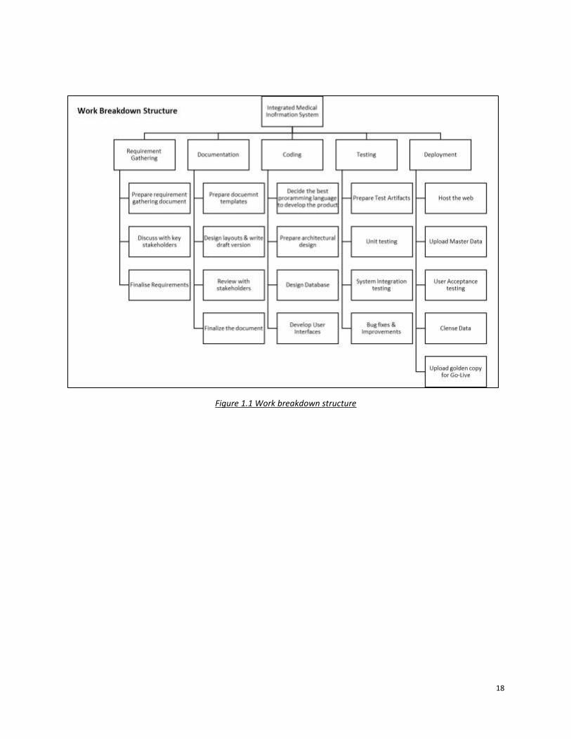
Figure 1.1 work breakdown structure displays the WBS of the hospital information system.
Requirement gathering, documentation, coding, testing, and deployment were the main
components of the work breakdown structure of the project and represents the first level of
the structure.
According to Figure 1.1, requirement gathering was subdivided into three levels namely
prepare requirement gathering document, discuss with key stakeholders and finalize
requirements. Documentation component expanded into four sublevels which comprised of
preparation of functional specification, screen designs, review and finalize with stakeholders.
Coding segment comprised of activities related to coding the system. Selection of coding
language, system architecture, design user interfaces and design of database structures
included in this section. System testing section depicted the unit testing and integration
testing related activities.
Finally, the deployment segment categorized the activities related to the deployment of the
Hospital Information System at a client site. User acceptance testing, cleanse and upload
master data and the go-live of the system were the important actives of this segment.
Thus, Figure 1.1 work breakdown structure provided a comprehensive breakdown of the
project work.
18
Figure 1.1 Work breakdown structure

19
1.7. Structure of the Dissertation
Chapter 2 discussed the evolution of health information systems, review of similar systems and
finally discussed the importance of the proposed solution.
Analysis of the problem, functional and non-functional requirements with use case diagram,
sequence diagram, database schema diagram, and entity relationship diagram were discussed in
Chapter 3. Further, it discussed the operating environment of the system.
Chapter 4 presents the evaluation techniques used to evaluate the product and it further
analyses the feedback received from evaluators. It also discussed the lessons learned during the
project and object which were unable to achieve.
Final Chapter provides the conclusion with the summary of results and expected future
enhancements of the hospital information system.

20
1.8. Summary
Introduction chapter explained the reasons for selecting the project and issues or problems
which are trying to solve by the system, objectives of the projects were also explained in this
chapter. Both functional and non-functional requirements were explained, and components
of the work breakdown structure were explained. To conclude the chapter, the remaining
chapters of the dissertation document was briefly described.

21
2. Background
Background chapter discusses the evolution of the hospital information system and then explains
existing similar information systems and the advantage of proposed systems against the existing
systems.
2.1. Evolution of Hospital Information Systems
Health information management is defined as the collection and analysis of healthcare data
to provide information for health care decisions involving patient care, institutional
management, health care policies, planning, and research.
The earliest forms of medical records were narratives written by ancient Greeks to document
successful cures, share observations about symptoms and outcomes, and teach others who
provided medical advice through these case studies.
As healthcare advanced, physicians realized that the best way to continue improving
diagnosing and treating illnesses was to carefully document observations and actions while
treating patients – and share this information as a way to teach other health professionals.
As early as 1600, physicians offered advice on how to present information in a medical record,
but it wasn’t until 1928 that the American College of Surgeons (ACOS) took steps to
standardize the growing number of medical records by establishing the American Association
of Record Librarians (AARL). “Record librarians” was the term used because early medical
records were documented on paper [2].
Standardization of medical records and growth of complete record-keeping continued from
the 1920s through the 1960s, but records were paper-based. The development of computers
presented the opportunity to maintain records electronically, but the expense of purchasing
and maintaining a mainframe, and the expense associated with storage of data, meant that
only the largest organizations could use technology to handle medical records. The 1960s also
saw the introduction of Medicare and Medicaid, which required nurses to collect data to
document care for reimbursement. While computers were increasingly used for accounting
and billing functions, the use of computers to collect and manage medical records was not
common [3].
In the 1970s, as computers became smaller, software designed to support clinical functions
for pharmacy, clinical laboratory, patient registration, and billing began to increase. The

22
disadvantage of these health information systems was their department-specific functions –
they were not accessible by other departments.
The first attempt at a total, integrated health records system was implemented in a
gynecology unit at the University Medical Center in Burlington, Vermont in 1971. Based on
the problem-oriented medical record, the system was patient-oriented – all disciplines
included in care made notes in the record to provide an overview of care to see the
relationship between conditions, treatments, costs, and outcomes.
Because personal computers and widespread health-related software applications had grown
in popularity, hospital information technology (IT) staff were tasked with the responsibility to
integrate multiple, disparate systems. As network solutions were developed, IT departments
were able to connect financial and clinical systems – for limited functions.
As competition in healthcare created a consolidation of individual hospitals to form health
systems, the need for integration grew. Technology advances gave hospitals access to
computing systems that could share information across disparate systems to set the stage for
data-sharing [4].
The importance of integrated electronic health records (EHRs) to enable providers to make
better decisions grew, and more hospitals and physicians implemented them to reduce the
incidence of medical error by improving the accuracy and clarity of medical records.
Increased focus on value-based care as opposed to fee-based care and a drive to improve
patient outcomes propel the growing accumulation of data to support clinical as well as
operational decisions in health care.
Just as clinicians in the 1920s understood the importance of previous health records as
learning tools that would improve outcomes, healthcare professionals leverage data to
enhance care on a larger scale — using tools that analyze population health data.

23
2.2. Review of Similar Hospital Information Systems
It was found that standalone hospital-section (eg: OPD, pharmacy, laboratory, etc)
management systems are available and used in some of the leading private hospitals as well
as few government hospitals of Sri Lanka. However, most of those systems were operating in
isolation and hence the users did not get the full benefits of those systems.
Following are a few examples,
• District Hospital, Dompe
Recently the e-Hospital concept was introduced to the district hospital of Dompe [5] by the
health ministry of Sri Lanka with collaboration with Information and Communication
Technology Agency of Sri Lanka (ICTA). The first hospital of its kind in Sri Lanka, this pioneering
healthcare institution has embraced the concept of digital health, which means that it now
uses information technology to improve the efficiency, competency, and quality of the
services it offers. It facilitates patient registrations, records their medical history, medicine
details, queue management, etc.
• Asiri Laboratories, Colombo
Allows patients to view their lab reports online. System generated user name and password
are provided with the laboratory bill.
• Lanka Hospitals, Colombo
Does register a few categories of patients (eg: pregnant mothers, babies born in the hospital,
etc) in their system. Bar code printed card issued however it does not record medical history
rather contain patient’s personal details.

24
There is a number of open-source and bespoke or off the shelf software solutions available
in the market to use in hospitals.
For example :
Open Source
• HospitalRun
HospitalRun is an open-source project [6], incubated and led by CURE International’s
technology team, aimed at delivering modern software for healthcare facilities in the
developing world. It utilizes modern browser-based software design and a user-friendly
interface to create an intuitive system. It is also architected to deal with the issues of Internet
reliability in a developing world context and is designed to allow records to be securely carried
outside of the hospital for mobile clinic activities.
Figure 2.1 HospitalRun System
• OpenMRS
OpenMRS is both a software and a community. As software, it serves as an electronic medical
record system (EMR) originally designed for developing countries. Through its open-source
community, it has grown into a medical informatics platform used on every continent.

25
OpenMRS is a software platform and a reference application which enables the design of a
customized medical records system with no programming knowledge (although medical and
systems analysis knowledge is required) [7].
It is a common platform upon which medical informatics efforts in developing countries can
be built. The system is based on a conceptual database structure which is not dependent on
the actual types of medical information required to be collected or on particular data
collection forms and so can be customized for different uses.
Figure 2.2 OpenMRS System
Off the Shelf Software
• VERTICAL Systems
Designed for clinics and hospitals, it is an on-premise medical billing solution that helps
manage patient records, billing, scheduling and financials on a centralized platform [8]. It
also supports document management, medical scheduling, medical workflows, medical
billing and claims, inventory management, ward management, nurse module, laboratory,
and pharmacy.

26
Figure 2.3 Vertikal System
• eHospital System
eHospital Systems is a customizable, comprehensive and integrated hospital management
system designed to manage all hospital operations [9]. Hospitals, it can be used by healthcare
facilities, multi-specialty clinics, and medical practitioners. The customizable alert system
sends the text and email reminders and improves the quality of patient care.
The software is user-friendly and with no error that is usually associated with handwriting.
Pulling up server or cloud information is now easily done with new technological computer
systems, yielding optimal performance. Patients can find doctors and book an online
appointment based on specialty, rating, fees, and availability. Organizing doctor schedules,
collating patient notes, and handling payment are effortless. It is developed based on the
best practices around the world.

27
Figure 2.4 eHospital System
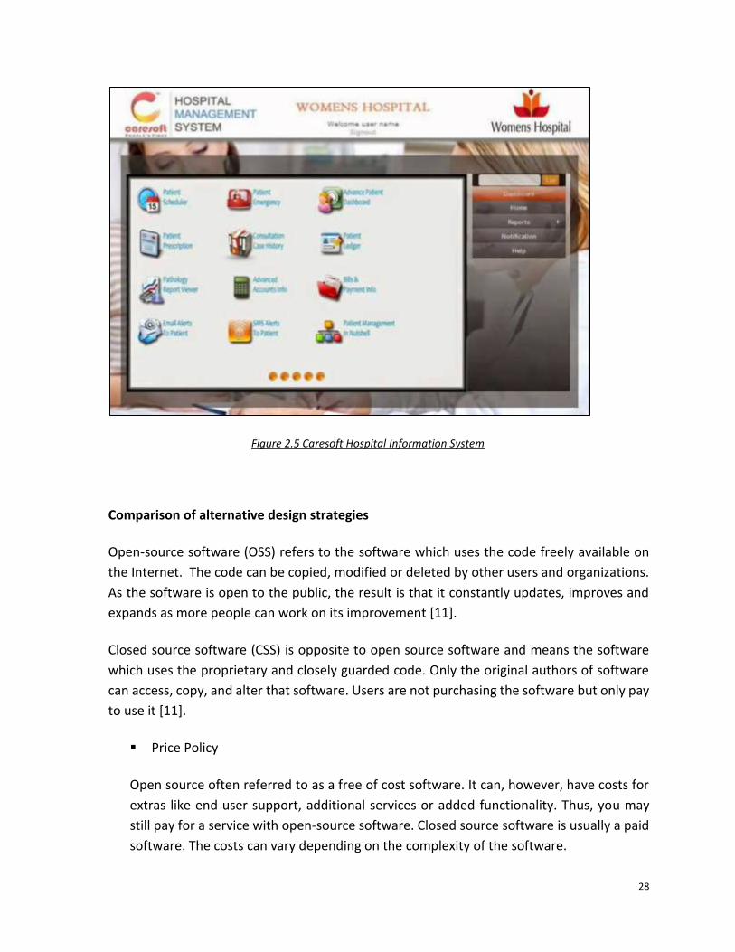
• Caresoft Hospital Information System
Caresoft – hospital information system is application software that is used for complete
automation of hospitals enabling enhancement inpatient care, resource and information
management leading to superior clinical and financial outcomes [10]. It helps health care
enterprises in delivering enhanced patient care, optimizing resource management using
Business Intelligence (BI) tools. It also helps in lowering the cost of operations and facilitates
effective decision making.
Key Features:
▪ Patient Information Management
▪ Appointment Management
▪ Electronic medical records
▪ Billing and Revenue Cycle Management
▪ Doctor Schedule and Appointments
▪ Modality (Diagnostic) Schedule and Appointments
▪ In-patient Management System
▪ Lab Information System
28
Figure 2.5 Caresoft Hospital Information System
Comparison of alternative design strategies
Open-source software (OSS) refers to the software which uses the code freely available on
the Internet. The code can be copied, modified or deleted by other users and organizations.
As the software is open to the public, the result is that it constantly updates, improves and
expands as more people can work on its improvement [11].
Closed source software (CSS) is opposite to open source software and means the software
which uses the proprietary and closely guarded code. Only the original authors of software
can access, copy, and alter that software. Users are not purchasing the software but only pay
to use it [11].
▪ Price Policy
Open source often referred to as a free of cost software. It can, however, have costs for
extras like end-user support, additional services or added functionality. Thus, you may
still pay for a service with open-source software. Closed source software is usually a paid
software. The costs can vary depending on the complexity of the software.

29
▪ Security
The code of open source software can be viewed, shared and modified by the community,
which means anyone can fix, upgrade and test the broken code. The bugs are fixed
quickly, and the code is checked thoroughly after each release. However, because of
availability, the source code is open for hackers as well.
On the contrary, closed source software can be fixed only by a vendor. If something goes
wrong with the software, Customer has to send a request and wait for the answer from
the support team. Solving the problem can take much longer than compared to Open
Source.
▪ Usability
Usability is a painful subject of open-source software. User guides are written for
developers rather than to layperson users. Also, these manuals are failing to conform to
the standards and structure.
For closed source software usability is one of the merits. Documentation is usually well-
written and contains detailed instructions.
It is apparent that each of the platform types has its own philosophy, methodology,
advantages, and disadvantages. Therefore there is no univocal option as it depends on
business needs.
When comparing both open source and off-the-shelf hospital information systems, it was
evident that open source software solutions provided a basic features such as patient
management, appointment scheduling, and pharmacy management while off-the-shelf
software’s offer more options, for instance, document management, medical scheduling,
medical workflows, medical billing and claims, inventory management, ward management,
nurse module, laboratory, and pharmacy.
Further following differences were identified among the open-source and off-the-shelf health
information systems.
• Open-source software’s were free of charge whereas the off the shelf software’s were
priced and price varies according to required modules. Further separate charges are
applicable for support services and user licenses.

30
• Open-source software provides a large amount of flexibility and freedom to change
the software without restriction. This innovation, however, may not be passed on to
all users and it is debated whether customized changes to the original source code
can limit the future support and growth of the software. Unlike open-source,
proprietary software also attracts larger amounts of research and development to
regularly offer new products and upgrades.
• Usability is often a major area of criticism for open source software because the
technology is generally not reviewed by usability experts and caters to developers
rather than the vast majority of new users. For off-the-shelf software, usability is a
high selling point due to expert usability testing for a more targeted audience. User
manuals are also provided for immediate reference and quick training, while support
services help to maximize the use of the software.
• Off-the-shelf software is generally seen as more secure because it is developed in a
controlled environment by a concentrated team with a common direction. Whereas
open source software is not always developed in a controlled environment, therefore,
those might vulnerable to security threats.
However, none of the ready-made solutions are provided an integrated solution as per the
proposed solution and none of them failed to provided reminders for upcoming vaccination
or appointments and organ donor/requester facilities. The proposed system would integrate
the information systems used in different sections of a hospital and hence it will be
convenient to users when performing their tasks and find information using a single system.
The proposed solution clearly had the upper hand compared to the existing information
systems designed for hospital management.

31
2.3. Summary
This chapter explained how the hospital information systems evolved over the years. It
explained how the necessity arose for information systems and how the systems grew
gradually. This chapter then focused on available similar information systems. It discussed
both open source and off the shelf software, their advantages and disadvantages and finally
the competitive edge of the proposed system over the existing systems.

32
3. Methodology
Methodology chapter elucidates the software development best practices used for product
development. Software development life cycle used for the project, relevant unified modeling
language (UML) diagrams and components of the operating environment of the system are
elaborated throughout the chapter.
3.1. Software Development Life Cycle
The waterfall model is a popular software development process. In “The Waterfall” approach,
the whole process of software development is divided into separate phases. The outcome of
one phase acts as the input for the next phase sequentially. That is any phase in the
development process begins only if the previous phase is completed.
The waterfall model is a sequential design process in which progress is seen as flowing
steadily downwards (like a waterfall) through the phases of requirement gathering and
analysis, system design, implementation, testing, deployment of system and maintenance.
Waterfall model is recommended to be applied if the project requirements are clearly
defined. Functional and non-functional requirements were agreed and finalized when the
project was selected and therefore the waterfall model was used as the guidance to develop
the product.
Sequential phases of the waterfall model with respect to the hospital information system
• Requirements: The first phase involved understanding what needed to be designed and
what should be its function and purpose. Here, the specifications of the input and output
or the final product are studied and marked. Therefore, a doctor, patient and a director
of a private hospital were contacted and discussed their experience, processes,
requirements, and suggestions.
• System Design: The requirement specifications from the first phase were studied and
system design was prepared. System design helped in specifying hardware and system
requirements and helped in defining overall system architecture.

33
• Implementation: With inputs from system design, the system was first developed in small
programs, which were integrated with the next phase. Each unit was developed
separately and tested for its functionality. Patient module, doctor module, lab module,
etc were developed as individual modules and unit testing was carried out.
• Integration and Testing: All the units developed in the implementation phase were
integrated into a single system after testing of each module. The designed software went
through constant integration testing to find out if there were any flaw or errors. Testing
was done so that the client does not face any problem during the installation of the
software.
• Deployment of System: Once the functional and non-functional testing was successfully
completed, the product was deployed in the customer environment.
• Maintenance: It is expected to make modifications to the system or an individual
component to alter attributes or improve performance after deployment of the product.
These modifications are expected to arise either due to change requests initiated by the
customer, or defects uncovered during live use of the system.

34
3.2. Use Case Diagram
A use case diagram is a graphic representation of the interactions between the elements of a
system [12]. That is, it is the primary form of system/software requirements for a new software
program underdeveloped. Use cases specify the expected behavior and not the exact method of
making it happen.
A key concept of use case modeling is that it helps to design a system from the end user's
perspective. It is an effective technique for communicating system behavior in the user's terms
by specifying all externally visible system behavior. It summarizes some of the relationships
between use cases, actors, and systems
Following use case diagrams display the use cases drew for each module. Six actors were
identified, and their behavior was illustrated in each diagram.
3.2.1. Patient
Figure 3.1 Patient Use Case Diagram
Patient
login
view diagnosis
view prescription
view reports
receive alerts
request organs
donate organs
add emergency details
register in the system

35
Activities of a patient-user are defined in Figure 3.1 patient use case diagram. A patient would
register in the system and then update the system with doner status. View diagnosis and
prescription details, view reports and receive alerts for different events were also activities that
permitted to a patient-user.
3.2.2. Doctor
A doctor user would be able to login to the system, view appointments and then would also be
able to write diagnosis and prescriptions for a patient. As per Figure 3.2 doctor use case diagram,
a doctor would be able to request laboratory reports and set upcoming event alerts as well.
Figure 3.2 Doctor Use Case Diagram
Doctor
login
view appointments
write prescription
write diagnosis
request reports
set alerts

36
3.2.3. Laboratory
Figure 3.3 laboratory use case diagram explained the actions of a laboratory user. The user would
be able to login to the system, view requested reports and then once the reports are ready to
collect, alert the user.
Figure 3.3 Laboratory Use Case Diagram
3.2.4. Pharmacy
Pharmacy-user acts similar to a laboratory user. As per Figure 3.4 pharmacy use case diagram, the
user would be able to login to the system, view prescriptions and then once the drugs are ready
to collect, alert the user.
Figure 3.4 Pharmacy Use Case Diagram
Lab
login
view reportrequest
ready reports
Pharmacy
login
view prescription request
ready prescription

37
3.2.5. Nurse
A nurse-user would log in to the system and would create appointments for doctors
Figure 3.5 Nurse User Case Diagram
3.2.6. Administrator
Figure 3.6 Admin Use Case Diagram
Figure 3.6 elucidates the actions permitted to the system administrator. Admin-user would
create other users in the system and would also be able to remove users including patients.
Nurse
login
Set Appointments
Admin
login
create user
remove user

38
3.3. Sequence Diagram
The sequence diagram is used primarily to show the interactions between objects in the
sequential order that those interactions occur. A sequence diagram is a good way to visualize and
validate various runtime scenarios. These can help to predict how a system will behave and to
discover responsibilities a class may need to have in the process of modeling a new system.
• Create new patient and make an appointment
Figure 3.7 Create New Patient Sequence Diagram
Above Figure 3.7 create new patient sequence diagram illustrates the time sequence diagram as
and when a new patient walks into the hospital. A patient will be registered in the system and a
system-generated bar code will be issued. An appointment to visit a doctor with date and time
will also be entered into the system.
Patient Registration Appointment
Create()
Register()
Date()
Time()

39
• Prescribed Laboratory Test
Following Figure 3.8 prescribed laboratory test sequence diagram depicts the sequence diagram
of the prescribed laboratory test report. A doctor recommends a test to be done. If the patient
decides the test to be done from the hospital’s laboratory, then it will appear in the laboratory
module. Results will be shown in the patient’s module under the doctor prescription.
Figure 3.8 Prescribed Laboratory Test Sequence Diagram
Doctor Test Report
GetTest()
GetReport()

40
3.4. Database Schema Diagram
A database schema is a visual and logical architecture of a database created on a database
management system. It provides a graphical view of the entire database architecture and
structure. It provides a means for logically grouping and displaying database objects such as
tables, fields, functions, and relations.
The system was designed with multiple database tables as shown in the Figure 3.9 database
schema diagram. Patient details are stored inpatient database table where patient_id is the
primary key. Similarly, all other database tables were created with suitable primary keys.
Relationships between each table were established.

41
Figure 3.9 Data Base Schema Diagram
appointments
appoint_id
title
date
time
doctor
patient_id
isAppointed
created_at
updated_at
pharmacies
pharm_id
is_ready
diagnose_id
created_at
updated_at
diagnoses
diagnose_id
diagnose
posted_date
doctor_id
created_at
updated_at
diagnose_value
diag_val_id
diagnose_id
hba1c
cholestrol
bp
created_at
updated_at
emergency_details
emergency_id
patient_id
contact_name
tel
created_at
updated_at
events
event_id
doctor_name
name
type
date
description
time
venue
patient_id
created_at
updated_at
patients
patient_id
full_name
address
tel_no
blood_group
patient_category
madical_condition
allergies
weight
height
dob
gender
created_at
updated_at
prescriptions
pres_id
prescription
diagnose_id
created_at
updated_at
laboratories
lab_id
title
description
report
is_ready
diagnose_id
patient_id
created_at
updated_at
users
user_id
name
password
user_type
speciality
created_at
updated_at
donations
donation_id
organ_name
description
type
posted_date
patient_id
created_at
updated_at

42
3.5. Entity Relationship Diagram
An Entity-Relationship (ER) Diagram is a type of flowchart that illustrates how “entities” such as
people, objects or concepts relate to each other within a system [13]. The entity-relationship
diagram displays the relationships of entity sets stored in a database.
An entity in this context is an object, a component of data. An entity set is a collection of similar
entities. These entities can have attributes that define its properties. By defining the entities,
their attributes, and showing the relationships between them, an ER diagram illustrates the
logical structure of databases.
Figure 3.10 Entity Relationship Diagram
VisitPatient
patient_id
name
agephone_no
address
blood_groupDoctor
doc_id name
speciality
Nurse nurse_id
name
Assists
Admin
admin_ID
name
designation
SuperviseSupervise
Supervise
Laboratory
lab_id
name
Phamacist
pharm_id name
Visit
Visit

43
3.6. Operating Environment
3.6.1. PHP
PHP (Hypertext Preprocessor) is a widely-used open source general-purpose scripting language
which is especially suited for web development and can be easily embedded into HTML code.
Therefore, PHP was used as the scripting language for the development of the product. It is
recommended to use PHP 7.0 or higher version for the application.
3.6.2. Apache
A PHP script is run on Apache HTTP web server. Apache HTTP Server is a freely-available open-
source web server software package. Apache provides a secure, efficient and extensible server
that allows HTTP services in sync with the current HTTP standards. Apache version 2.4.x required
to be used with the system.
3.6.3. The backend of the application
Database of the system uses MySQL. MySQL is an oracle-backed open-source relational database
management system (RDBMS) based on Structured Query Language (SQL). It is most often
associated with web applications and online publishing. The system was tested with MySQL
version 8.0
The system currently supports Microsoft Windows environment only.
3.6.4. Disaster Recovery and System Backup
It is recommended to place a disaster recovery plan for the system. A daily system backup is
required to be taken and stored in a separate location. The disaster recovery server is required
to be located in a separate location and it is required to be accessible in the event of failure of
the regular server.

44
Figure 3.11 operating environment diagram displays a basic operating environment of the
system. A server should be connected to the firewall which provides network security. Users of
the system such as a doctor, pharmacist, lab assistant, etc would be connected to the system via
a router.
Figure 3.11 Operating Environment

45
3.7. Summary
This chapter explained the waterfall software development life cycle used as the guidance to
develop the project and how its stages were used during the project. Use case diagram and
time sequence diagram were explained as those helped in designing the system. The
database diagram which consists of database tables and their relationships was also
discussed in the chapter. Thereafter the entity-relationship diagram of the system was
illustrated. Finally, the operating environment where the hardware and networking setup of
the system was explained.

46
4. Evaluation
Evaluation chapter discusses the criteria used to measure the success of the system. The methods
used to obtain the user feedback and the results of the responses are explained. Suggestions for
the improvement of the system and lessons learned throughout the project are also contained
in this chapter.
User evaluation was carried out mainly to identify how satisfied the users are with the system.
The decision to continued with the project or not would depend on critical evaluation. Heuristic
evaluation is an informal method of identifying the problems associated with the user interface.
Objectives of the evaluation include assessing the relevance, effectiveness, efficiency, impacts,
and sustainability of the project and its activities. Objectives also include what challenges were
faced during the implementation of the project, important lessons learned and
recommendations for the future project implementation.
4.1. Evaluation Approach
The system was demonstrated to a selected group of twenty individuals comprised of patients,
health sector personnel and a hospital administrator. Thereafter they were asked to use the
system and provide the feedback on the given questionnaire. (Refer: Appendix A).
The questionnaire was developed based on the following principles.
• Problems and Needs (Relevance)
• Achievement of Purpose (Effectiveness)
• Sound management and value for money (Efficiency)
• Achievement of wider effects (Impact)
• Likely continuation of achieved results (Sustainability)

47
4.2. Evaluation Results
Summary of feedback of the evaluators was displayed in Table 4.1 evaluation results.
No Object Extremely Satisfied
Satisfied Somewhat
satisfied Not so
satisfied Not at all satisfied
1 Look & Feel 9 7 2 2 0
2 Ease of use 8 6 1 3 2
3 Reliability 8 7 3 1 1
4 Security 5 9 3 2 1
5 Value for money 4 7 5 3 1
6 Recommend to friend 7 5 8 0 0
Table 4.1 Evaluation Results
4.3. Analysis of Results
Feedback received from the user evaluation questionnaire were counted and summarized
visually using pie charts.
A pie chart displays data, information, and statistics in an easy-to-read 'pie-slice' format with
varying slice sizes illustrates how much of one data element exists. The bigger the slice, the more
of that particular data was gathered. The evaluation helped to identify whether the developed
system had achieved the project objectives or not.

48
4.3.1. Look and Feel of the system
The pleasantness of the system is assessed with the following pie chart in Figure 4.1 look
and feel of the system.
Figure 4.1 Look and feel of the system
Results
Extremely Satisfied
Satisfied Somewhat satisfied
Not so satisfied
Not at all satisfied
Look and Feel 9 7 2 2 Table 4.2 Look and feel of the system
According to the Figure 4.1 look and feel of the system, 90% of users were satisfied with
the user interface of the system while 10% of users, that is just two users as per the Table
4.2 look and feel of the system were not so satisfied with the look and feel of the system.
Therefore, the majority of the users were satisfied with the system hence we could
conclude that the design of the system was satisfactory.

49
4.3.2. Ease of use of the System
User-friendliness of the system was measured from this question. Logical order,
navigation, and simplicity of understanding the system were the quantified. Results were
illustrated in Figure 4.2 ease of use of the system and Table 4.3 ease of use of the system.
Figure 4.2 Ease of use of the system
Results
Table 4.3 Ease of use of the system
As per Figure 4.2 ease of use of the system, 25% of users were not satisfied with the user-
friendliness of the system while the rest of the users found that the system was user-
friendly. It was found that the main reason for the unsatisfactory was some users were
using the system for the first time without proper training.
Extremely Satisfied
Satisfied Somewhat satisfied
Not so satisfied
Not at all satisfied
Ease of use 8 6 1 3 2

50
4.3.3. Reliability of the System
Assessing the trustworthiness or the consistent performance of the system was the
objective of this question and the results are graphically represented in the below Figure
4.3 reliability of the system.
Figure 4.3 Reliability of the system
Results
Table 4.4 Reliability of the system
Majority of users i.e. about 90%, felt confident about the system however Table 4.4
reliability of the system showed that two users were not satisfied with the reliability of
the system but they were not mentioned reasons for their decision.
Extremely Satisfied
Satisfied Somewhat satisfied
Not so satisfied
Not at all satisfied
Reliability 8 7 3 1 1

51
4.3.4. Security of the System
Users were explained about the security of the system. An authorization matrix was
maintained and access to the system modules will be based on the user role. For instance,
a patient will not be able to access to doctor’s dashboard. Though the authorization was
not implemented to the existing system, the user opinion was obtained for future
references. User responses were summarized in the below Figure 4.4 security of the
system and Table 4.5 security of the system.
Figure 4.4 Security of the system
Results
Table 4.5 Security of the system
According to the pie chart shown in Figure 4.4 security of the system, it was revealed that
85% of the users were satisfied with the proposed authorization and other security
measures of the system. As of the Table 4.5 security of the system, three users were
unsatisfied with the security measures. It is found that those users were satisfied with
user-based authorization roles but wanted more system-wise security measures.
Extremely Satisfied
Satisfied Somewhat satisfied
Not so satisfied
Not at all satisfied
Security 5 9 3 2 1

52
4.3.5. Recommend to friend
The objective of this question was to get an idea of whether users will encourage their
friends and family to enrol the system and results would beneficial in the event of
releasing the product to market. User feedback is illustrated in the pie chart given in the
below Figure 4.5 recommend to a friend and actual results are shown in Table 4.6
recommend to a friend.
Figure 4.5 Recommend to a friend
Results
Table 4.6 Recommend to a friend
As shown in both Figure and Table 4.6, the results were very satisfactory. All users were
responded favourably as they would recommend the system to their friends and family.
35%
25%
40%
Recommend to friend
Extremely Satisfied
Satisfied
Somewhat satisfied
Not so satisfied
Not at all satisfied
Extremely Satisfied
Satisfied Somewhat satisfied
Not so satisfied
Not at all satisfied
Recommend to friend 7 5 8 0 0

53
4.3.6. Thoughts on how to improve the system
Users were given a free space to write down their thoughts on how to improve the
system. Following were their significant suggestions.
• Integrate an appointment system or interface with existing appointment systems
eg: eChannelling, Doc990
• Facility to prepare medical bills
• Introduce ward management module
• Inventory management module for stores, pharmacy, laboratory, etc
• Tele-doctor facility. Ability to get the doctor option via online, video conferencing,
over the telephone, etc
• Deliver drugs to the door-step facility
• Facility to manage complaints
• Insert chatbot
• More reports and statistics
Further discussions and analysis of suggestions would help to identify the essential
features of the system. It is expected to gradually include those identified features to the
system with future releases.

54
4.4. Lessons Learnt and Failure to achieve objectives
This was the first-ever development of this scale performed by the developer. He had not any
previous experience of developing a complete software product. Further, the knowledge of PHP
was limited to basic commands and operations. Therefore, the biggest challenge was to develop
the system while learning PHP language.
It was tough to conduct development of this scale while learning. Was stuck on some stages and
had to seek the help of either online or friends. Yet, it was managed to get the system completed
overcoming all obstacles.
Two deliverables related to the following objectives of the project were unable to achieve.
Nevertheless, the rest of the deliverables were accomplished successfully.
• Increase electronic medical records coverage of hospitals
› Facilitate to keep patient medical history in a smart card/barcode
The system was designed to retain a patient’s medical history and it was supposed to record
medical history in a smart card or bar code. The hardware requirement (smart cards, bar code
readers and bar code printers) prevent the implementation of the objective. However, the
system is capable of recording patient history and it may be possible to deploy in a future
release.
• Improve quality and efficiency in service delivery, governance, accountability and
effective use of resources of a hospital.
› SMS Alerts
The system was supposed to send SMS alerts to remind patients about forthcoming
appointments. , The requirement of SMS gateway which was supposed to purchase was
prevented implementation of SMS alerts. Yet, email alerts were conFigured and deployed
successfully. SMS alerts could be deployed with a future commercial release of the product.

55
4.5. Summary
The chapter started with the explanation of the base of project evaluation. Results of the user
feedback were illustrated and analyzed with relevant tables and charts. Thereafter the
chapter emphasizes the system improvements suggested by the users. Finally, the lessons
learned by the developer throughout the project development and objectives which were
unable to achieve were revealed in the evaluation chapter.

56
5. Conclusion
This chapter presents a summary of the results of the project and future improvements.
5.1. Summary of Results
A web-based hospital information system was developed based on the requirements of different
stakeholders of a hospital. It comprised of six modules namely patient, doctor, laboratory,
pharmacy, nurse and administrator. Each module has its own set of features, for instance, email
alerts, reports, etc. and comprehensively integrated with each other. Evaluators of the system
confirmed that the software was up to the expected standards. Foremost of the benefits of the
system are as follows:
• Automation of the system improves the efficiency
• The user-friendly graphical user interface provided easy to use system
• Effectively overcome the delays in communication
• System security, data security, and reliability are the striking features
5.2. Future Enhancements
The system is open for future enhancements. The existing system did not facilitate financial
transactions, therefore, the immediate improvement would modify the system to connect with
payment gateway and equip with the financial module.
The system should also need to be integrated with different laboratory systems used in the
hospital to get the laboratory reports directly without manual intervention. The existing system
is capable of integration with external systems.
eChannelling & DOC990 are popular online appointment creation service providers in Sri Lanka.
Therefore, the hospital information system should be integrated with such service providers
which would be convenient to users.
The hospital management system would also provide an inventory management system for
departments like pharmacy, laboratory, etc which would eliminate the requirement of
maintaining separate software for the same.
These enhancements would provide the hospital management system a distinctive advantage
over its competitors in the market once the system is commercially launched.

57
References
1. Vladimir Zwass. Information System. [Online].
Available : https://www.britannica.com/topic/information-system
2. Morris F Collen M.D. Origins of Medical Informatics [Online]. Available:
https://www.ncbi.nlm.nih.gov/pmc/articles/PMC1307150/?page=1
3. The History of Health Information Management – from then to now. [Online]. Available:
https://liaison.opentext.com/blog/2017/05/02/history-heath-information-management-now/
4. Joshua R Vest and Larry D Gamm. Health information exchange: persistent challenges and new strategies. [Online]. Available: https://www.ncbi.nlm.nih.gov/pmc/articles/PMC2995716/
5. Digital Health Project. Information and Communication Technology Agency (ICTA) – Sri Lanka.
[Online]. Available: https://www.icta.lk/projects/digital-health/
6. HospitalRun. Free, easy-to-use software for developing world healthcare. [Online]. Available:
http://hospitalrun.io/
7. OpenMRS. A free, open-source electronic medical record platform. [Online]. Available:
https://openmrs.org/
8. VERTICAL Systems. Medical Software for Clinics and Hospitals. [Online]. Available: http://www.ehr-
medical-software.com/index.htm
9. eHospital System. [Online]. Available: https://www.adroitinfosystems.com/products/ehospital-
systems
10. Caresoft. [Online]. Available: https://caresoft.co.in/
11. Khrystyna Oliinyk. 5 Differences Between Open Source and Closed Source Software. [Online].
Available: https://api2cart.com/business/5-differences-between-open-source-and-closed-source-
software/
12. What is use case diagram. [Online]. Available: https://www.visual-paradigm.com/guide/uml-unified-
modeling-language/what-is-use-case-diagram/
13. What is an entity relationship diagram. [Online]. Available: https://www.lucidchart.com/pages/er-
diagrams

58
Appendix A: Project Evaluation Form
Project Evaluation Form
Instructions for filling out this form:
This form is an aid for the identification of strengths and weaknesses in the performance of the Integrated
Hospital Information System. Please be as objective when filling out this form. I will use this information
to reinforce the software’s strengths and to find ways to eliminate weaknesses.
1. How satisfied you are with the look and feel of this software (User Interface)?
Extremely Satisfied
Satisfied
Somewhat satisfied
Not so satisfied
Not at all satisfied
2. How satisfied you are with the software’s ease of use?
Extremely Satisfied
Satisfied
Somewhat satisfied
Not so satisfied
Not at all satisfied
3. How satisfied you are with the reliability of this software?
Extremely Satisfied
Satisfied
Somewhat satisfied
Not so satisfied
Not at all satisfied

59
4. How satisfied you are with the security of this software?
Extremely Satisfied
Satisfied
Somewhat satisfied
Not so satisfied
Not at all satisfied
5. How likely is it that you would recommend this software to a friend or family member?
Extremely likely
Likely
Somewhat likely
Not so likely
Not at all likely
6. Do you have any thoughts on how to improve this software?

60
Appendix B: Functional Specification
Integrated Hospital Information System
Functional Specification

61
1. Purpose
The purpose of this document is to present the functional specification of the Integrated Hospital
Information System. Design of the screens, navigation through screens and functions of each
screen are presented in this document.
2. System Features
Please note that screen design, content, and navigation are subjected to change during the
development of the system
2.1. Main Page
The main page of the system should be as follows
Figure 2.1 Home Page
• Click on “Login” icon should direct the user to login page

62
2.2. Login Page
A registered user should be able to enter his/her credentials and login to the system
New User
• A new patient-user should be able to register himself to the system
• Staff users should be created by the Administrator
Figure 2.2 Login Page
2.3. Sign-Up Page
• Click on Sign up icon in the login page would result below user registration screen
RUHUNU HOSPITALS (PVT) LIMITED
Health Information System
LoginUser Name
Password ***************
Forget password ? Click here
Sign up
Remember me
SIGN IN

63
Figure 2.3.1 Sign up Page
• Print bar code button will print bar code in an external material
• Click on Personal Information will open the following screen
• Click on the SAVE button will save the data
Figure 2.3.2 Personal Information
• Click on Medical Information will open the following screen
• Click on the SAVE button will save the data
Home > User > SignUp
RUHUNU HOSPITALS (PVT) LIMITED
Health Information System - User Registration
Personal Information
First Name : Middle Name : Last Name : Date of Birth : Sex :
Address :
Nearest Town:
Mobile Phone Number : E-Mail :
Medical Information
Emergency Contact
SAVE

64
Figure 2.3.3 Medical Information
• Click on Emergency Contact will open the following screen
• Click on the SAVE button will save the data
Figure 2.3.4 Emergency Contact
RUHUNU HOSPITALS (PVT) LIMITED
Health Information System - User Registration
Home > User > SignUp
Personal Information
Medical Information
Blood Type:
Allergies :
Special Concerns :
Emergency Contact
SAVE
RUHUNU HOSPITALS (PVT) LIMITED
Health Information System - User Registration
Home > User > SignUp
Personal Information
Medical Information
Emergency Contact
Name :
Relationship :
Contact Details : Mobile : Home :
SAVE

65
2.4. Home Page
Once the user successfully logged in to the system following home page will appear
Figure 2.4 Home Page
Following explanations are on the assumption of a patient logged in to the system
2.5. User Page
• Click on icon in the Home page would results screens drew under 2.3 Sign-
up page
• User Should be able to change/update data.
2.6. Medical Page
• Click on icon in the Home page would result below screen
• This will display the medical prescription details of the user
RUHUNU HOSPITALS (PVT) LIMITED
Health Information System
User Medical Lab Reminders Pharmacy Doner

66
Figure 2.6.1 Selection Screen
• User will select a date range and doctor name and press execute
• Date range - mandatory / Doctor name – Optional
• The following results screen will appear
• It will be a Display only screen
• Click on icon will pop-up any attached documents
Figure 2.6.2 Results Screen
RUHUNU HOSPITALS (PVT) LIMITED
Health Information System - Medical Records
Date To
Execute
Doctor
RUHUNU HOSPITALS (PVT) LIMITED
Health Information System - Medical Records
Date Doctor
21.10.2017 Dr. G D E S Jayawardena
Descr iption
The symptoms themselves may be difficult to identify. An occasional headache may be just a
headache, or it could be a symptom of a larger problem.

67
2.7. Lab Page
• Click on icon in the Home page will result below screen
• This will display the laboratory test report details of the user
Figure 2.7.1 Selection Screen
• User will select a date range and press execute
• The following results screen will appear
• It will be a Display only screen, but the user will be able to download if required
• Click on icon will pop-up any attached documents
• If the user wishes to get the reports done from outside, then the user should be able to
attach such reports in the system.
• There could be following types
o Reports
o X-Rays
o Scan
RUHUNU HOSPITALS (PVT) LIMITED
Health Information System - Laboratory
Date To
Execute

68
Figure 2.7.2 Results Screen
2.8. Reminders
• Click on icon in the Home page will result below screen • This screen will display the forthcoming appointments and users are also able to set
reminders
Figure 2.8.1 Reminders Screen
• Initially following appointment types will be conFigured
▪ Doctor Appointments
▪ Vaccination
▪ Medical Test appointments
RUHUNU HOSPITALS (PVT) LIMITED
Health Information System - Reminders
Future Appointment Information
Set Reminders

69
Figure 2.8.2 Future appointment information
• User will be able to set reminders themselves
• Click on the “Save” button would save data
• Upon the due date, an SMS will be delivered to the given mobile number
Figure 2.8.3 Set Reminders
RUHUNU HOSPITALS (PVT) LIMITED
Health Information System - Reminders - Future Appointments
Set Reminders
View
Future Appintment Information
Date Type Title
RUHUNU HOSPITALS (PVT) LIMITED
Health Information System - Reminders - Set Reminders
Future Appintment Information
Set Reminders
Reminder Type
Title
Date
Time
SAVE

70
2.9. Pharmacy
• Click on icon in the Home page will results pharmacy screen
Figure 2.9.1 Selection Screen
• User will enter a date range and press the “execute” button • Results screen would be as follows
• It will display whether the drugs were issued from Hospital pharmacy or not
Figure 2.9.2 Results Screen
RUHUNU HOSPITALS (PVT) LIMITED
Health Information System - Pharmacy
Date To
Execute
RUHUNU HOSPITALS (PVT) LIMITED
Health Information System - Pharmacy
Date Doctor Prescr iption Details Inhouse/Outside

71
2.10. Organ Donations /Requests
• Click on button will result the organ donations/requests screen
Figure 2.10.1 Organs donation/requests Screen
• Organ requests will list down the existing organ requirements
Figure 2.10.2 Organs requests Screen
RUHUNU HOSPITALS (PVT) LIMITED
Health Information System - Organ Donation/Requests
Organ Requests
Donate Organ
RUHUNU HOSPITALS (PVT) LIMITED
Health Information System - Organ Donation/Requests
Organ Requests
Donate Organ
Patient Details Organ DetialsType

72
• User will be able to mention the organ donation details using the “Donate organ”
option
Figure 2.10.3 Donate organ Screen
2.11. Doctor
When a doctor logged into the system his home page will be as of below
Figure 2.11 Doctor Screen
• The doctor will be able to view his personal details
• Appointments for the day
• Organ donor requests and donations
RUHUNU HOSPITALS (PVT) LIMITED
Health Information System - Organ Donation/Requests
Organ Requests
Donate Organ
Organ Type
Blood Group
Contact Details
SAVE

73
2.12. Laboratory
• Laboratory user will have following home page
• User will be able to search for laboratory requests
• New/Open, Completed, postponed statuses will be sed to segregate requests
Figure 2.12.1 Selection Screen
• Following results screen will appear according to the selection parameters
• User will able to post results when it is ready
Figure 2.12.2 Results Screen
RUHUNU HOSPITALS (PVT) LIMITED
Health Information System - Laboratory
Date To
Execute
Open Completed Postpone
RUHUNU HOSPITALS (PVT) LIMITED
Health Information System - Laboratory
Date Status Type Repor t Descr iption Patient ID

74
2.13. Pharmacy
• Pharmacy user will have following home page
• User will be able to search for drug requests
• New/Open, Completed, postponed statuses will be sed to segregate drug requests
Figure 2.13.1 Selection Screen
• Following results screen will appear according to the selection parameters
• User will able to post results when it is ready
Figure 2.13.2 Results Screen
RUHUNU HOSPITALS (PVT) LIMITED
Health Information System - Pharmacy
Date To
Execute
Open Completed Postpone
RUHUNU HOSPITALS (PVT) LIMITED
Health Information System - Pharmacy
Date Status Doctor Name Prescr iption Patient ID
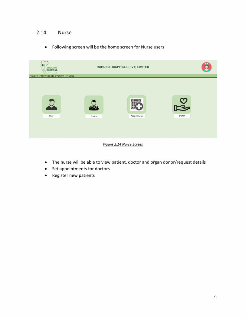
75
2.14. Nurse
• Following screen will be the home screen for Nurse users
Figure 2.14 Nurse Screen
• The nurse will be able to view patient, doctor and organ donor/request details
• Set appointments for doctors
• Register new patients
RUHUNU HOSPITALS (PVT) LIMITED
Health Information System - Nurse
Doctor Appointments Doner User

76
Appendix C: Technical Specification
Integrated Hospital Information System
Technical Specification

77
1. Purpose
The purpose of this document is to present the technical specification of the Integrated
Hospital Information System.
2. Operation Environment
2.1. Software Requirement
• ASP.Net 4.0 or higher
• EXT.Net 1.2 or higher
• SAP .NET Connector 3.0 or higher
• Office Web Components 2003 or higher
• Fusion Charts 3.2.4 or higher
• IIS 7.0 or higher
• Email Server
• Windows Server R2 (64 Bit)
2.2. Hardware Requirement
The hardware requirement is to be analyzed and implemented by the client.
2.3. Web Browser Requirement
Hospital Information system requires following web browsers for it to run:
• Google Chrome V50+
• Firefox 60+

78
3. General Development Standards
• Depending on the data type all the input fields should be validated with appropriate
messages
• Depending on the character length all input fields should be limited to hold only the
maximum characters allowed in the respective data field. Ex. A text box to input First
Name. The respective data fields type is ‘varchar(100)’. The text field that takes the First
Name as the input should not allow the user to type more than 100 characters in it.
• Invalid character validation. Ex. Want to validate special characters such as a <html>,
<script>
• Accessibility: Users who are given access to the Hospital Information System
4. Code Extractions
Important code extractions are listed below
4.1. Manage Users
• Model – User
• Controller – AdminController
/**
* Display the specified resource.
*
* @param int $id
* @return \Illuminate\Http\Response
*/
public function show()
{
$users = new User();
$filterParams = [];
if(request()->has('filter_enabled') && request('filter_enabled') === 'true'){
if(request()->has('user_name') && request('user_name') !== null){
$users = $users->where('name', 'like', '%'.request('user_name').'%');
$filterParams['user_name'] = request('user_name');
}
if(request()->has('email') && request('email') !== null){
$users = $users->where('email', request('email'));
$filterParams['email'] = request('email');
}
if(request()->has('user_type') && request('user_type') !== null){
$users = $users->where('user_type', request('user_type'));

79
$filterParams['user_type'] = request('user_type');
}
}
return view('admin.pages.admin_dashboard',[
'users'=>$users->get(),
'filterParams' => $filterParams
]);
}
/**
* Store a newly created resource in storage.
*
* @param \Illuminate\Http\Request $request
* @return \Illuminate\Http\Response
*/
public function store()
{
$data = request()->validate([
'name' => 'required|string',
'user_type'=> 'required',
'email' => 'required|email',
'password' => 'required|string|min:6',
'speciality' => ''
]);
$data['password'] = Hash::make($data['password']);
$data['email_verified_at'] = Carbon::now();
User::create($data);
return redirect()->back()->with('message','User created successfully');
}
/**
* Delete a user from storage.
*
* @param \Illuminate\Http\Request $request
* @return \Illuminate\Http\Response
*/
public function delete($id)
{
User::find($id)->delete();
return redirect()->back()->with('message','User removed successfully');
}

80
4.2. Add Diagnosis
• Model – Diagnose
• Controller – DiagnoseController
/**
* Store Diagnose and Prescription
* @param Request $request
* @return \Illuminate\Http\RedirectResponse
*/
public function store(Request $request){
$validatedData = $request->validate([
'diagnose' => 'required',
'prescription' => 'string',
]);
$diagnoseValues = [];
DB::beginTransaction();
try {
$result=Diagnose::create([
'diagnose'=>$validatedData['diagnose'],
'patient_id'=>request('patient_id'),
'posted_date'=>Carbon::now(),
'doctor_id'=>Auth::id()
]);
Prescription::create([
'prescription'=>$validatedData['prescription'],
'diagnose_id'=>$result['id']
]);
if (request('pharmacy_type') === '0' ){
Pharmacy::create([
'diagnose_id'=>$result['id'],
'is_ready'=>false,
]);
}
if(request()->has('cholesterol') && request('cholesterol') !== null){
$diagnoseValues['cholesterol'] = request('cholesterol');
}
if(request()->has('bp') && request('bp') !== null){
$diagnoseValues['bp'] = request('bp');
}
if(request()->has('hba1c') && request('hba1c') !== null){
$diagnoseValues['hba1c'] = request('hba1c');
}
if(count($diagnoseValues) > 0){
$diagnoseValues['diagnose_id'] = $result['id'];
$diagnoseValues['created_at'] = Carbon::now();
$diagnoseValues['updated_at'] = Carbon::now();
DiagnoseValue::create($diagnoseValues);
}
DB::commit();
return redirect()->back()->with('diagnose_id',$result['id'])->withSuccess('Diagnose Added Successfully !')
->with('active_tab', 'add_diagnose');

81
}catch (Exception $exception){
DB::rollback();
return redirect()->back()->withErrors('Something went wrong !');
}
4.3. Make Donations
• Model – Donations
• Controller – DonationController
/**
* Show Donation page
* @return \Illuminate\Contracts\View\Factory|\Illuminate\View\View
*/
public function show(){
return view('patient.pages.organ',[
'donations'=>Donation::where('patient_id',Patient::getPatient(Auth::id())['id'])->get()
]);
}
/**
* Store Donations
* @param Request $request
* @return mixed
*/
public function store(Request $request){
$validatedData = $request->validate([
'organ_name' => 'required|string',
'description' => 'required|string',
'type'=>'required'
]);
$validatedData['posted_date']=Carbon::now();
$validatedData['patient_id']=Patient::getPatient(Auth::id())['id'];
Donation::create($validatedData);
return Redirect::back()->withSuccess('Donation request submitted successfully !');
}
/**
* Show Donation page
* @return \Illuminate\Contracts\View\Factory|\Illuminate\View\View
*/
public function showDonations(){
return view('patient.pages.organ',[
'donations'=>Donation::where('patient_id',Patient::getPatient(Auth::id())['id'])->where('type','Donate')->get()
]);
}
/**
* Show Donation page
* @return \Illuminate\Contracts\View\Factory|\Illuminate\View\View

82
*/
public function showRequests(){
return view('patient.pages.organ',[
'donations'=>Donation::where('patient_id',Patient::getPatient(Auth::id())['id'])->where('type','Request')->get()
]);
}
4.4. Add Appointments
• Model – Appointment
• Controller – AppoinmentController
* Display the specified resource.
*
* @param int $id
* @return \Illuminate\Http\Response
*/
public function show()
{
// $unreg_appoinments = UnregisteredAppoinment::where('doctor',Auth::user()->name)
// ->where('date',Carbon::today())->get();
return view('doctor.pages.all_appoinments',[
'appoinments' => Appoinment::getAppointmentByDate(Carbon::now()),
'date'=>Carbon::now()->toDateString()
// 'unreg_appoinments'=>$unreg_appoinments
]);
}
/**
* Store a newly created resource in storage.
*
* @param \Illuminate\Http\Request $request
* @return \Illuminate\Http\Response
*/
public function store()
{
$data = request()->validate([
'title' => 'required|string',
'time' => 'required',
'date' => 'required|date',
'doctor' => 'required|string',
'patient_id' => 'required'
]);
$data['isAppointed'] = '1';
$response = Appoinment::updateOrCreate(['date'=>$data['date'],
'patient_id'=>Patient::where('id',$data['patient_id'])->value('id')],$data);
return $response->wasRecentlyCreated == true ? redirect()->back()->with('message','Appointed Successfully') :
redirect()->back()->with('message','Appointment Made Before');
}

83
/**
* Store a newly created resource in storage.
*
* @param \Illuminate\Http\Request $request
* @return \Illuminate\Http\Response
*/
public function storeUnregisterd()
{
$data = request()->validate([
'name' => 'required|string',
'title' => 'required|string',
'time' => 'required',
'date' => 'required|date',
'doctor' => 'required|string',
]);
$data['isAppointed'] = '1';
$response = UnregisteredAppoinment::updateOrCreate(['date'=>$data['date'],'name'=>$data['name']],$data);
return $response->wasRecentlyCreated == true ? redirect()->back()->with('message','Appointed Successfully') :
redirect()->back()->with('message','Appointment Made Before');
}
/**
* Update the specified resource in storage.
*
* @param \Illuminate\Http\Request $request
* @param int $id
* @return \Illuminate\Http\Response
*/
public function update(Request $request, $id)
{
//
}
/**
* Filter Appintment by Date
* @return \Illuminate\Contracts\View\Factory|\Illuminate\View\View
*/
public function filter(){
$date=request('date_picker');
return view('doctor.pages.all_appoinments',[
'appoinments' => Appoinment::getAppointmentByDate($date),
'date'=>$date
]);
}

84
4.5. Add Emergency Details
• Model – EmergencyDetail
• Controller – EmergencyDetailController
/**
* Display the specified resource.
*
* @param int $id
* @return \Illuminate\Http\Response
*/
public function show($id)
{
$data=EmergencyDetail::where('patient_id',Auth::id())->get();
return view('patient.pages.my_profile',['details'=>$data]);
}
/**
* Store a newly created resource in storage.
*
* @param \Illuminate\Http\Request $request
* @return \Illuminate\Http\Response
*/
public function store()
{
$data = request()->validate([
'contact_name' => 'required|string',
'tel' => 'required|numeric',
]);
$data['patient_id']=Auth::id();
EmergencyDetail::updateOrCreate(['patient_id'=>Auth::id()],$data);
return redirect()->route('show_patient_myprofile', ['active_tab' => 'emergency_contact']);
}
4.6. Add Event
• Model – Event
• Controller – EventController
/**
* Store a newly created resource in storage.
*
* @param \Illuminate\Http\Request $request
* @return \Illuminate\Http\Response
*/

85
public function store(Request $request)
{
$data=request()->validate([
'name' => 'required|string',
'type' => 'required|string',
'date' => 'required|date',
'description' => 'required',
'time' => 'required',
'venue' => 'required',
'patient_id' => 'required'
]);
$data['doctor_name'] = Auth::user()->name;
Event::create($data);
$user = User::find((int)request('patient_id'));
$user->notify(new NewEventAdded());
return redirect()->back()->with('active_tab', 'add_events')->withSuccess('Event Added Successfully !');
}
4.7. Request Lab Reports
• Model – Laboratory
• Controller – LabReportController
/**
* Request lab reports
* @param Request $request
* @return \Illuminate\Http\RedirectResponse
*/
public function store(Request $request){
if(request('diagnose_id') === null){
return redirect()->back()->with('active_tab', 'request_lab_report')
->withErrors('You have to add Diagnose record first !');
}
$validatedData = $request->validate([
'report-title' => 'required',
'report-description' => 'string|required',
]);
Laboratory::create([
'title'=>$validatedData['report-title'],
'description'=>$validatedData['report-description'],
'is_ready'=>(int)0,
'patient_id'=>$request->patient_id,
'diagnose_id'=>request('diagnose_id'),
]);
return redirect()->back()->with('diagnose_id',request('diagnose_id'))
->with('message',$validatedData['report-title'].' report requested successfully !')
->with('active_tab', 'add_events');
}

86
4.8. Add and Update Patients
• Model – Patient
• Controller – PatientDetailController
/**
* Show the patient detail view
* @return \Illuminate\Contracts\View\Factory|\Illuminate\View\View
*/
public function show(){
return view('patient.pages.patient_details',[
'patient_categories'=>config('constances.patient_categories'),
]);
}
/**
* Store Patient details
* @param Request $request
* @return view
*/
public function store(Request $request){
$validatedData = $request->validate([
'full_name' => 'required|max:255',
'address' => 'required|string',
'tel_no' => 'required|numeric',
'gender' => 'required|string',
'blood_group'=>'required|string',
'dob' => 'required',
'height' => 'required|string',
'weight' => 'required|string',
'patient_category' => 'required|string',
'allergies' => 'required|string',
'medical_condition' => 'required|string'
]);
$validatedData['user_id']=Auth::id();
$validatedData['patient_category']=config('constances.patient_categories')[\request('patient_category')];
$patient_detail=Patient::create($validatedData);
return Redirect::route('show_patient_myprofile');
}

87
4.9. Download Lab Reports
• Model – Laboratory
• Controller – CompletedRequestsController
/**
* show completed request view
* @param $report_id
* @return \Illuminate\Contracts\View\Factory|\Illuminate\View\View
*/
public function show($report_id){
return view('lab.pages.completed_request',[
'diagnose'=>Diagnose::getSingleReport($report_id),
'report'=>Laboratory::where('id',$report_id)->first()
]);
}
/**
* download report
* @param $report_id
* @return \Symfony\Component\HttpFoundation\BinaryFileResponse
*/
public function download($report_id){
$report=Laboratory::find($report_id);
$pathToFile = storage_path('app/public/upload/' . $report->report);
return response()->download($pathToFile);
}
4.10. Upload Lab Reports
• Model – Laboratory
• Controller – SingleRequestsController
/**
* Upload report
* @param Request $request
* @return mixed
*/
public function update(Request $request){
$validatedData = $request->validate([
'report' => 'required',
]);
$file=$validatedData['report']->getClientOriginalName();
$validatedData['report']->storeAs('public/upload',$file);

88
$validatedData['report']=$file;
$validatedData['is_ready']=(int)1;
$report=Laboratory::find(request('report_id'));
$report->update($validatedData);
return Redirect::back()->withSuccess('Report Uploaded Successfully !');
}
4.11. Upload Prescriptions
• Model – Pharmacy
• Controller – DiagnoseController
/**
* Store Diagnose and Prescription
* @param Request $request
* @return \Illuminate\Http\RedirectResponse
*/
public function store(Request $request){
$validatedData = $request->validate([
'diagnose' => 'required',
'prescription' => 'string',
]);
DB::beginTransaction();
try {
$result=Diagnose::create([
'diagnose'=>$validatedData['diagnose'],
'patient_id'=>request('patient_id'),
'posted_date'=>Carbon::now(),
'doctor_id'=>Auth::id()
]);
Prescription::create([
'prescription'=>$validatedData['prescription'],
'diagnose_id'=>$result['id']
]);
if (request('pharmacy_type') === '0' ){
Pharmacy::create([
'diagnose_id'=>$result['id'],
'is_ready'=>false,
]);
}
DB::commit();
return redirect()->back()->with('diagnose_id',$result['id'])->withSuccess('Diagnose Added Successfully
!');
}catch (Exception $exception){
DB::rollback();
return redirect()->back()->withErrors('Something went wrong !');
}

89
4.12. Download Prescriptions
• Model – Patient
• Controller – PDFController
/**
* Display a listing of the resource.
*
* @return \Illuminate\Http\Response
*/
public function getPDF($id)
{
$prescription = Diagnose::where('diagnoses.id', $id)
->join('patients', 'diagnoses.patient_id', 'patients.id')
->join('users', 'diagnoses.doctor_id', 'users.id')
->join('prescriptions', 'diagnoses.id', 'prescriptions.diagnose_id')
->select(
'diagnoses.posted_date as prescribed_date',
'diagnoses.diagnose',
'prescriptions.prescription',
'prescriptions.id as prescription_id',
'users.name as doctor_name',
'patients.full_name as patient_name',
'patients.dob as patient_dob'
)->first();
$diagnoseValues = DiagnoseValue::where('diagnose_id', $id)->first();
$pdf = PDF::loadView('patient.pages.prescription',[
'prescription' => $prescription,
'diagnoseValues' => $diagnoseValues
]);
return $pdf->download('prescription.pdf');
}

90
Appendix D: User Manual
Integrated Hospital Information System
User Manual

91
1. Purpose
The purpose of this document is to assist users to use the Hospital Information System
without difficulties.
2. Home Page
• Home page of the system

92
• Login Screen
› Click on the “Login” button will result below screen
No. Action ROC Value
(01)
Login: Email Address: Password: Remember Me
C C O
Enter registered email and password Tick if want to remember user name and password

93
3. Patient
• Register
› Click on “REGISTER” icon on the top right-hand corner of the ‘Home’ page
› The results screen will as below
› Press “Register” button – Following screen will appear
No. Action ROC Value
(01)
Patient Registration: Name: Email address: Password: Confirm Password:
C Enter suitable details

94
› Press the “Save Details” button
› User will direct to “Patient Dashboard” page
› Click on “Emergency details” tab and enter emergency contact details
No. Action ROC Value
(02)
Patient Details: Full Name: Address: Contact No: Gender: Blood Group: Date of Birth: Height(m): Weight(kg): Patient Category: Allergies: Medical Condition:
C Enter suitable details

95
› Click the “Save or Update” button
• Organ donation/request registration
› Select ‘Organ Donation/Request’ from the menu on the left-hand side of the screen.
No. Action ROC Value
(03)
Patient Details: Contact Name: Contact No:
C
Enter suitable details

96
› Click the “Save” button.
› A successful data entrance will result in the following message
› Click on “All”, “Donations”, “Requests” buttons will filter data accordingly
No. Action ROC Value
(04)
Organ Donation/Requests: Organ Name: Type: Description
C
Type: select Donation or Request

97
• Reset Password
› Select “Settings” from the menu on the left-hand side of the screen.
› Enter a new password and click on “Save Changes” button.
• Medical History
› Select “Medical History” from the menu on the left-hand side of the screen.

98
› Results screen – Patient Dashboard would be as follows
› List down the doctor channeling history in the “Diagnoses” tab.
› Click on the “More” button will display the details of the particular selected Doctor visit.
› If a user decides to get the medical reports from an external laboratory, the user will be
able to attach the same
▪ Click on “Choose File” button to search documents from the computer and
attach the report
▪ Click on “Upload Report” button will save data.

99
› Prescriptions tab → Displays the prescription history. “Download Prescription” button
will allow the user to download the prescription.

100
› Self Uploaded Reports tab → Displays the user uploaded report to the system. If
required, the user will also be able to download the report
› Lab Reports tab → Consists of laboratory reports uploaded by the hospital laboratory.
User will be able to download the report by click on the “Download Report” button.
› Events Tab → will display upcoming events set by a Doctor

101
› Static Reports Tab → This tab display reports based on the patient category
Example: A diabetic patient would be able to view two reports namely HbA1C and
Cholesterol while a heart patient would view Blood Pressure and Cholesterol report.
View report: Click on a report then select the required date range and click on the
“Search” button

102
• Logout
› A click on the user name will pop out the “Logout” button

103
4. Doctor
• Doctor Dashboard
› Log into the system with the given user name and password.
› A doctor would be able to search patients by following parameters
▪ Patient Name
▪ Gender
▪ Patient Category
› Click on the “Search” button would filter the list and “Reset Filters” button would clear
filters
› Click on the “More” button next to a patients’ name, will result below screen

104
› Add Diagnosis tab → Doctor could diagnosis and prescription. Enter values for
‘Cholesterol’ and ‘Blood Pressure ’ [Note: value fields would be changed based on patient
category]
› Select either ‘Hospital Pharmacy’ or ‘External Pharmacy’ from the drop-down.
› Click on the “Save” button will save data
› Request Lab Report tab → allows the doctor to request laboratory reports

105
› Patient Diagnosis History Tab → Displays the previous doctor visits of the patient
› Add the Events Tab section→ allows entering future events for a patient
› Fill the required details and click on the “Submit Event” button will save data

106
• Donations
› Click on ‘Donations” in the header panel, will result in the following screen
› Displays all donations and requests for Organs
No. Action ROC Value
(01)
Add Event: Event Name: Patient type: Date: Event description: Time Venue:
C O C C C O
Enter data as applicable

107
• Appointments
› Click on ‘Appointments’ in the header panel will result in the following screen
› User will be able to filter appointments for a date
› Click on the “More” button will direct to patient’s profile
• Click on the user name will pop out the “Logout” button and will enable the user to sign out
from the system

108
5. Laboratory
• A successful login to the system will result in the following dashboard screen
› Reports can be filtered by the following options
▪ Report title
▪ Patient name
▪ Doctor name
▪ Report status
▪ Date
› Click on the “More” button will result in the following screen

109
› Click on “Choose file” to browse relevant report and attach to the request
› Click on the “Ready” button will save the report and status will change to “Ready”
• Click on ‘Users’ button in the header panel will display the following screen. It allows users to
reset their password
• Click on the user name will pop out the “Logout” button to sign out from the system

110
6. Pharmacy
• A successful login to the system will result following Pharmacy Dashboard screen
• If a patient decides to take the prescribed drugs from the hospital pharmacy, such requests will
appear in the following dashboard
› Requests can be filtered by using the following options
▪ Patient name
▪ Doctor name
▪ Status
▪ Date

111
› Click on the “More” button will result in the following screen
› Once the drugs are ready to collect, click on the “Ready” button
• Click on ‘Users’ button in the header panel will display the following screen. It allows users to
reset their password
• Click on the user name will pop out the “Logout” button to sign out from the system

112
7. Nurse
• A successful login to the system will result following ‘Nurse Dashboard’ screen
• The result screen will list down all registered patients
• Patients can be filtered by the following parameters
▪ Patient name
▪ Gender
▪ Patient category

113
• Click on the “Make Appointment” button will result in the following screen
• A doctor can be searched by name or specialty.
› Click on the “Make Appointment” button will save an appointment for the selected
doctor
› The “Reset” button will clear-out the data entered
No. Action ROC Value
(01) Add New appointment: Select Doctor: Appointment Title: Time: Date:
C C C C
Select doctor from the list

114
8. Administrator
• A successful login to the system will result following ‘Admin Dashboard’ screen

115
• Create New Users
› Doctor
› Other users – Nurse, Pharmacy, Laboratory

116
› Click on the “Submit” button will save data
• All Users
› Displays all users created in the system
› Filtering can be done by User name, Email address or user type
› “Remove user” button will erase users from the system
No. Action ROC Value
(01)
Add New user: Name: User type: Specialty: Email address: Password:
C C R C C
User type: Doctor/Nurse/Lab/Pharmacy Specialty: Applicable only for user type - “Doctor”


![Integrated Hospital Management System [IHMS]](https://img.dokumen.tips/doc/110x75/5868ed2e1a28ab3d3a8b4b81/integrated-hospital-management-system-ihms.jpg)
