Embed Size (px)
Citation preview

NASA / CR-1998-208441
Integrated Airport Surface Operations
S. Koczo
Rockwell Collins Avionics and
Advanced Technology Center
Cedar Rapids, Iowa
Communications
National Aeronautics and
Space Administration
Langley Research CenterHampton, Virginia 23681-2199
Prepared for Langley Research Centerunder Contract NAS1-19704
July 1998
https://ntrs.nasa.gov/search.jsp?R=19980223080 2020-07-26T15:52:39+00:00Z

Available from the following:
NASA Center for AeroSpace Information (CASI)7121 Standard Drive
Hanover, MD 21076-1320
(301 ) 621-0390
l_:ational Technical Information Service (NTIS)
5285 Port Royal Road
Springfield, VA 22161-2171('703) 487-4650

Abstract
The current air traffic environment in airport terminal areas experiences substantial delays when
weather conditions deteriorate to Instrument Meteorological Conditions (IMC). Expected future
increases in air traffic will put additional pressures on the National Airspace System (NAS) and will
further compound the high costs associated with airport delays. To address this problem, NASA has
embarked on a program to address Terminal Area Productivity (TAP). The goals of the TAP program
are to provide increased efficiencies in air traffic during approach, landing, and surface operations in
low-visibility conditions. The ultimate goal is to achieve efficiencies of terminal area flight
operations commensurate with Visual Meteorological Conditions (VMC) at current or improved
levels of safety.
During the last year, research activity culminated in the development, flight test and demonstration of
a prototype Low-Visibility Landing and Surface Operations (LVLASO) system. A NASA led
industry team and the FAA developed the LVLASO flight test system, integrating airport surfacesurveillance, aeronautical data link, DGPS navigation, automation systems, and controller and flight
deck displays and interfaces. The LVLASO system supports both controllers and flight crews with
guidance, control and situational awareness information to achieve improved efficiencies and safetyof surface operations in IMC weather conditions. The LVLASO system was tested and demonstrated
to a wide range of aviation industry members at the Atlanta Hartsfield International Airport during
August, 1997.
This report describes the demonstration system and documents the activities pertaining to the
development of the LVLASO demonstration system as part of the ATOPS Task 16 contract. Inaddition to the development and support of the LVLASO demonstration system this task also
examined future TAP data link and to a lesser extent the avionics equipment and integrity
requirements that must be considered for future LVLASO deployment.

.
2.
.
Table of Contents
Introduction
LVLASO Flight Test / Demonstration System Description
2.1 System Overview of Integrated Surface Operations
2.2 LVLASO Demonstration System
2.2.1 LVLASO Ground System Architecture
2.2.2 Airborne Systems
2.3 LVLASO Sub-System Description and Performance Results
2.3.1 DGPS Sub-System
2.3.2 VHF Data Links
2.3.2.1 VHF DGPS Data Link Coverage Tests (van taxi tests)
2.3.2.2 VHF Traffic and AMASS Holdbar Data Link
2.3.2.3 LVLASO Flight Test VHF Data Link Performance (DGPS)
2.3.3 Mode-S Data Link
2.3.3.1 CPDLC Data Link
2.3.3.2 ADS-B
TAP Data Link
3.1 Introduction
3.2 Aeronautical Data Link Overview
3.2.1 Future CNS/ATM Data Link System
3.2.2 Aeronautical Telecommunications Network (ATN)
3.2.3 Overview of VHF Data Link (VDL)
3.2.3.1 ACARS VDL Mode 1
3.2.3.2
3.2.3.3
3.2.3.4
3.2.3.5
Summary of VDL Mode 2
Summary of VDL Mode 3
Summary of VDL Mode 4
Summary of VDL Mode Capabilities
Paze
1-1
2-1
2-1
2-3
2-3
2-5
2-7
2-7
2-7
2-7
2-12
2-15
2-24
2-24
2-25
3-1
3-1
3-2
3-2
3-3
3-3
3-3
3-8
3-8
3-9
3-11

.
3.2.4 Overview of Mode-S Data Link
3.3 Overview of Planned CNS/ATM Data Link Applications
3.3.1 CPDLC
3.3.2 ADS-A/C
3.3.3 ADS-B
3.3.3.1 ADS-B Data Link Considerations
3.3.3.2 ADS-B and ACAS (Airborne Collision Avoidance System)
3.3.3.3 Ground Interrogation of Aircraft Mode-S Registers
3.3.4 DGPS/DGNSS (LAAS)
3.3.5 FIS, FIS-B
3.3.6 TIS, TIS-B
3.3.7 AOC/AAC
3.3.8 Air-Air Crosslink
3.4 Allocation of CNS/ATM Data Link Applications to Data Link
3.5 Candidate Avionics Data Link Architectures for CNS / ATM and TAP
3.5.1 VHF Radio Resource Requirements versus Data Link Allocation Options
3.6 TAP and CNS/ATM Data Link Summary / Conclusions
Avionics Integration, Relxofit and Integrity Issues for LVLASO
3-13
3-17
3-17
3-18
3-19
3-20
3-21
3-24
3-24
3-25
3-26
3-26
3-27
3-28
3-25
3-35
3-47
4-1
Appendix A
Appendix B
Appendix C
Appendix D
Appendices
VHF DGPS Data Link Coverage Test Results
Data Link Equipment Interfaces, Schematics and Protocols
Mode-S CPDLC Data Link - Interfaces and Protocols
Terminal Area Productivity (TAP) Data Link
iii

Figure2-1
Figure2-2
Figure2-3
Figure2-4
Figure2-5
Figure2-6
Figure2-7
Figure2-8
Figure2-9
Figure2-10
Figure2-11
Figure2-12
Figure2-13
Figure2-14
Figure2-15
Figure2-16
Figure2-17
Figure2-18
Figure3-1
Figure3-2
Figure3-4
Figure3-5
Figure3-6
Figure3-7
Figure3-8
List of Figures
Integrated Surface Operations System Concept 2-2
LVLASO Ground System 2-4
NASA 757 Experimental System Architecture 2-6
Differential GPS Base Station and Data Link 2-7
Coverage Test of Runways and Taxiways (Control Tower using Vertical Polarization) 2-9
Coverage Test of Ramp Area (Control Tower using Vertical Polarization) 2-9
Control Tower Antenna Installation 2-10
Renaissance Hotel Antenna Installation 2-10
Jeppesen Chart of Atlanta Hartsfield Airport 2-16
Flight Test Scenario #1 2-18
Flight Test Scenario #2 2-19
Flight Test Scenario #3 2-20
Flight Test Scenario #4 2-21
Flight Test Scenario #5 2-22
Flight Test Scenario #6 2-23
NASA 757 ADS-B Surveillance Coverage ,_Taxi Scenario to South Half 2-25
NASA 757 ADS-B Surveillance Coverage roFlight Scenario 2-26
LVLASO Data Link and GPS Equipment l_ack on NASA 757 2-26
Planned CNS/ATM Data Link Services 3-4
CNS/ATM Data Link System 3-6
Aeronautical Telecommunications Network 3-7
VDL Mode 4 Configurations for ADS-B 3-45
VDL Mode 4 Configurations for ADS-B and AOC/AAC 3-45
VDL Mode 4 Configurations for ADS-B, AOC/AAC, FIS / FIS-B / TIS-B 3-46
VDL Mode 4 Configurations for CPDLC, ,_d)S-B, AOC/AAC, FIS / FIS-B / TIS-B 3-46
iv

Table 2-1
Table 2-2
Table 2-3
Table 2-4
Table 2-5
Table 2-6
Table 2-7
Table 2-8
Table 3-1
Table 3-2
Table 3-3
Table 3-4
Table 3-5
Table 3-6
Table 3-7
Table 3-8
Table 3-9
Table 3-10
Table 3-11
Table 3-12
Table 3-13
List of Tables
Message Reception Probability vs Number of Transmission Attempts (van tests) 2-11
Qualitative Comparison of Transmit Site Performance (van tests) 2-11
ARINC 429 Message Input Interface to VI-IF Data Links 2-13
Airport Status Message Format 2-13
Hold Bar Bit Map 2-14
Target Information Message Format 2-18
Message Reception Probability vs Number of Transmission Attempts (757 tests) 2-17
LVLASO CPDLC Messages 2-24
Planned CNS/ATM Data Link Services 3-5
ADS-B Data Link Issues for Mode-S and VDL Mode 4 3-12
Current Mode-S GICB Register Definition (Mode-S SARPs) 3-14
Data Link Applications / Data Link Cross Reference 3-16
Summary of Information Needs for Applications Supported by ADS-B 3-20
Summary of ADS-B Air-to-Air Performance Requirements for Support of 3-22
Indicated Applications
Summary of ADS-B Requirements for ATS Provider Surveillance and 3-23
Conflict Management Applications (as a function of Flight Phase)
Candidate Data Links for future CNS/ATM Data Link Applications 3-29
(Terminal Area and Airport Surface Operations)
Candidate Data Links for future CNS/ATM Data Link Applications 3-30
(Enroute Operations - non-remote areas)
Candidate Data Links for future CNS/ATM Data Link Applications 3-31
(Oceanic/Remote Area Enroute Operations)
Data Link Allocations Per Application Groups 3-32
Radio Resource Requirements as a function of Data Link Allocation Option 3-37
Radio Resource Requirements as a function of Data Link Allocation Option 3-44

1.0 Introduction
With the advent of global, satellite-based navigation and data link communications technology, the
aviation industry is now able to address air space solutions that provide for more efficient and safe air
travel. Two such areas are the Future Air Navigation System / Air Traffic Management
(FANS/ATM) system and airport terminal area capacity improvement initiatives. At present, much of
the industry's focus is on the development of the Communications, Navigation and Surveillance
(CNS) / ATM system with primary focus on enroute operations since immediate cost benefits are
expected. One of the end goals of CNS/ATM is free flight, supported by seamless aeronautical data
link communications, automatic dependent surveillance, and air traffic management by Air Traffic
Control (ATC).
NASA Langley and NASA Ames Research Centers are also working to improve airport capacities via
the Terminal Area Productivity Program (TAP). NASA's TAP Program is intended to support the
industry with the development of appropriate technologies and system solutions, and also to involve
industry in achieving improved efficiency and safety of terminal area operations, particularly during
low-visibility weather conditions.
This report is in support of NASA's TAP program, addressing Low Visibility Landing and Surface
Operations (LVLASO). Specifically, this report documents the activity related to NASA's Industry
Demonstration and Flight Tests of LVLASO Technologies this past August at the Atlanta Hartsfield
International Airport.
TAP Overview
The goal of NASA's TAP program is to achieve clear-weather capacities in terminal area operations
in instrument weather conditions. Objectives are to develop and demonstrate integrated systems
technologies and procedures that enable productivity of the airport terminal area to match that ofvisual conditions.
The four major components of TAP are 1) Low-Visibility Landing and Surface Operations
(LVLASO), 2) Reduced Separation Operations (RSO), 3) Air Traffic Management, and
4) Aircraft and ATC Systems Integration.
LVLASO objectives are to develop and demonstrate an aircraft navigation, guidance and control
system for surface operations to achieve or exceed safety and efficiency of visual operations under
non-visual operations down to Cat III B conditions, while being compatible with evolving surface
movement ground control automation. To accomplish these objectives, NASA has developed the
Taxiway Navigation and Situational Awareness (T-NASA) system, which provides the flight crew
with guidance and situational awareness information using integrated cockpit displays. In addition to
T-NASA, LVLASO also includes the development of a dynamic runway occupancy measurement
(DROM) system to determine the proper spacing of aircraft pairs during landing. LVLASO also
addresses a high-speed Roll-Out Turn-Off (ROTO) system which assists the crew to achieve or
improve upon visual condition runway occupancy under non-visual conditions.
RSO objectives are 1) to develop an Advanced (Wake)Vortex Spacing System (AVOSS) to be coupled
with appropriate ATC automation aids, allowing dynamic separation standards for aircraft pairs; 2) to
develop a capacity enhancing concept for integrating current flight management system (FMS)
capabilities with emerging ATC automation aids, and 3) to develop and demonstrate a flight-deck based
monitoring / surveillance system of aircraft on simultaneous, independent parallel approaches, allowing a
reduction in parallel runway spacings to less than 3,400 ft during non-visual conditions.
1-1
Objectives of TAP Air Traffic Management are to develop and demonstrate enhanced CenterTRACON Automation System (CTAS) automation aids to more fully utilize FMS and data link
capabilities for increased airport capacities, utilize CTAS enhancements to incorporate dynamic
separation standards and enable closely-spaced runway operations, and to allow for rapid
reconfiguration of operational runways and airspace for te_xninal area operations.
Aircraft-ATC system integration objectives are to develop systems modeling / studies as tools to
support TAP objectives and to provide guidelines for ongoing research and development, to improve
understanding of root causes of inefficiencies in operations, project cost benefits for proposed
concepts, develop procedures and technical solutions for safe and effective integration of flight deck
and ATC operations, and to provide integrated flight test capability to demonstrate TAP products.
Flight tests and demonstration are planned in each area of "rAP, with eventual integration of all TAP
components into an overall demonstration of Terminal Area Productivity. The flight test and
demonstration of the LVLASO system at Atlanta earlier this year was a major milestone for NASA in
its TAP / LVLASO program goals.
Organization of Report
The primary activity of this task contract was to provide technical and equipment support for NASA's
flight tests and subsequent industry demonstration of Low-Visibility Landing Approach and Surface
Operations (LVLASO) technologies at Atlanta's Hartsfield International Airport. Subsequently the
major portion of this report focuses on the development of the LVLASO demonstration system and
available flight test results. Section 2 provides a top-level description of the LVLASO system thatwas demonstrated. Section 2 also examines each of the individual LVLASO sub-systems that were
supported as part of the larger industry team in more detail, including description of interfaces,
protocols and test results. In addition to avionics support to NASA's LVLASO demonstration,
additional study activities were as follows:
1) Develop data link requirements for NASA's Terminal &tea Productivity (TAP) program, i.e., data
link requirements for terminal area operations in the frture CNS/ATM airspace system.
2) Examine aircraft integration and avionics integrity issues related to providing Integrated Surface
Operations capabilities to new and retrofit aircraft.
Section 3 discusses TAP data link and Section 4 addresses aircraft avionics equipment, integration
and integrity issues related to LVLASO.
1-2

2.0 LVLASO Flight Test / Demonstration System Description
This section provides a description of the LVLASO system that was tested and demonstrated atthe
Atlanta Harts field International Airport during August, 1997. The Atlanta LVLASO test system
represents a significant integration of several complex sub-systems by NASA, FAA and a number of
industry partners. The majority of these sub-systems are expected to play an important role in the
future CNS/ATM airspace system that will be used to provide benefits for both, free flight and also
airport surface operations.
Before discussing the Atlanta LVLASO system that was implemented, it is useful to briefly review
the expected components of an end-state Integrated Surface Operations system (such as the Airport
Surface Movement Guidance and Control System {ASMGCS} concept being developed by RTCA
SC-159). This allows a comparison of the generic end-state system with the one that was tested and
demonstrated at Atlanta.
2.1 System Overview of Integrated Surface Operations
An Integrated Surface Operations / ASMGCS system has a diverse set of requirements that it must
address and requires a wide range of technologies and system interactions to achieve high-traffic
density operations during low-visibility conditions. This system must be capable of providing precise
guidance and control for a range of aircraft and vehicle types throughout the airport movement and
ramp areas in all types of weather conditions. The system must provide adequate separation and
taxiway/runway incursion protection (especially in low-visibility conditions) and must provide
planning and management of traffic in high-traffic densities and for complex airport layouts. The
Surface Operations / ASMGCS system must also be compatible with the overall Air Traffic
Management system that enables gate-to-gate operations.
Figure 2-1 provides a conceptual illustration of an Integrated Surface Operations system. Top-level
system functions are surveillance, traffic routing, guidance, control, and detection and prevention of
taxiway/runway incursions. In addition, data link plays a key role in enabling communications
between end users and the various surface operations sub-systems.
Some of the technologies and systems that will likely play a role in an Integrated Surface Operations /
ASMGCS system are:
1. Satellite-based navigation (Global Navigation Satellite System, GPS)
a) Local Area Augmentation System (LAAS)
b) Wide Area Augmentation System (WAAS)2. Data link
3. Surveillance
4. Advanced information presentation displays
5. Ground automation systems
a) Surface Movement Advisor (SMA) providing traffic routing and planning
b) Airport Movement Area Safety System (AMASS) providing runway incursion alerts
c) Smart airport lighting, e.g., SMGCS
6. Airport data bases
7. Airport lighting
8. High-speed Roll-out Turn-Off (ROTO)
9. Head-up displays
10. Enhanced Vision Systems
2-1

O
r_
O
N
N
2-2

2.2 L VLASO Demonstration System
The system demonstrated at Atlanta consists of several subsystems that were integrated to
provide the intended capabilities of increased situational awareness and guidance information to
air traffic controllers and pilots in conducting efficient and safe surface operations. Both groundsub-systems and airborne sub-systems provide services to meet the overall operational goals.
2.2.1 LVLASO Ground System Architecture
The LVLASO ground system is shown in Figure 2-2 and consists of the following sub-systems:
1. Surface surveillance sub-system
a) Airborne Surface Detection Equipment (ASDE-3) surface radar (skin-paint radar,
counterpart to primary radar used in enroute surveillance).
b) Airport Traffic Identification System (ATIDS)
Multilateration surveillance on transponder transmissions
(signal received by multiple sites, position calculated from time-of-arrival of signals
at each site)
Automatic Dependent Surveillance broadcast (ADS-B)
(GPS position reports using Mode-S extended squitters)
c) Airport Movement Area Safety System (AMASS)
- Automation system that provides runway incursion warnings
- Data fusion of surveillance reports from ASDE-3, ATIDS and ARTS (Automated
Terminal Radar System)
2. VHF Traffic data link (broadcast uplink of traffic information and runway holdbars)
3. Differential GPS (DGPS) base station and VHF DGPS data link (broadcast uplink of DGPS
corrections information)
4. Controller Pilot Data Link Communications (CPDLC)
5. Data Acquisition
(data recording of all ground system data transactions, e.g., DGPS uplink information,
CPDLC messages, and Traffic Data_
The physical location of ground systems was as follows: 1) surveillance systems and VHF Traffic
data link were located at the Atlanta control tower; 2) the DGPS base station, VHF DGPS data link,
the Controller Interface, and one of the five ATIDS (or CAPTS) Receiver/Transmitters (ground
portion of Mode-S link) were located at the Renaissance Hotel located immediately to the North of
the airport.
A room in the Renaissance Hotel was set up as a pseudo ATC tower cab, with a test controller
serving to intercept actual controller voice communications to the NASA 757 research aircraft
(which served as the test vehicle) and converting them to data link messages. A remote AMASS
display was provided via modem link to provide the surface traffic display that controllers
typically see. Video telemetry of live video of NASA 757 aircraft displays (head-down taxi
display (HDD) and the head-up display (HUD)) and outside visual scenes from nose and tail-
mounted cameras on the 757 was provided for viewing in the hotel "demonstration" room.
2-3

• m
• Q
:=
c0_ 6 I..>---' _D
0 a
I
_0
m_I
I
I
==
r_.<.1
.1
dl
=.m
2-4

2.2.2 Airborne Systems
The NASA 757 experimental system architecture is shown in Figure 2-3. LVLASO aircraft sub-
systems are as follows:
1. Data Links
a) VHF Traffic broadcast data link receiver
b) VHF DGPS broadcast data link receiver
c) CPDLC via Mode-S link
d) ADS-B downlink broadcast using Mode-S extended squitters
2. Airborne GPS receiver
(provides DGPS position accuracies using DGPS corrections inputs from VHF DGPS data link)
3. Displays
a) Airport moving map LCD display (HDD)
b) Roll-out, turn-off and taxi guidance HUD
4. Pilot input device
(allows pilot to select display modes and zoom levels; also serves as data link
acknowledgment to CPDLC messages).
5. Data acquisition system
(data recording of all aircraft system data transactions, e.g., received and transmitted data
link messages, GPS sensor outputs, etc.)
The next section examines each of the LVLASO sub-systems that were supported by Collins in
more detail and includes performance results where they are available. The LVLASO sub-systems
supported by Collins are:
1) DGPS base station
2) VHF data links
a) Traffic broadcast transmitter and receiver
b) DGPS broadcast transmitter and receiver
3) Airborne GPS sensor
4) Mode-S transponder and associated Airborne Data Link Processor (ADLP)
(The ADLP provides the Mode-S Specific Services (MSSS) for ADS-B and CPDLC)
5) LCD Head Down Display (HDD) taxi display and Remote Interface Unit (RIU)
(RIU provides interface between NASA Silicon Graphics computer and the LCD HDD)
2-5

o.1
"11:)m
iiI i
• I
2
m
I
.,
'l
I
l
I
I
'l
L
w
m
O_:o,',g_
o
"_ o0_0
nor)..-,0
1
ii
c:
ofr"
_E
I
ml mmll
i -- -"i co_l) l:i...-,mm
_ _mm
_m_ _ m17=m
m
m m
l
I
m
Im
a:
ol
ma _,D_.O
-_.
r_
Zm m
e-°_
o
Q.
m
om
2-6

2.3 L VLASO Sub-System Description and Performance Results
This section describes each sub-system in more detail and, when available, provides performance
results and observations based on data collected during preliminary sub-system tests and also
during the actual LVLASO flight tests and industry demonstrations.
2.3.1 DGPS Sub-System
A Collins DGPS base station provided the DGPS corrections information, which was then broadcast
via VHF DGPS data link. Figure 2-4 shows the DGPS base station and VHF data link configuration.
A Collins GNR-4000 GPS receiver in the NASA 757 provided DGPS position reports for use by
aircraft systems. NASA used a GPS survey system on the ground and onboard the aircraft (Ashtec
GPS) to record "truth" position data for later post-processing. Initial DGPS performance results
indicate the following performance for a 30 minute flight test nm (other runs appear similar):
1) Horizontal RMS position error (mean = 0.728 m, standard deviation = 0.485 m)
2) Cross track error (mean = 0.056 m, standard deviation =0.494 m)
3) Along track error (mean = -0.142 m, standard deviation =0.706 m)
Active
TAntenna
COM 1
GPSReceiver
COM2
/Corrections
RS232 "-
I
ARINC
RS232to ] 429 I VHF I
AoRlnNveCrt4ey_ Tranimitter
I Tune II Head I
Figure 2-4 Differential GPS Base Station and VHF Data Link
2.3.2 VHF Data Links
Two identical pairs of broadcast VHF data links were utilized for 1) DGPS corrections uplink
and 2) Traffic and AMASS runway holdbar information uplink. The VHF data links are
prototype 31.5 kbps, D8PSK modulation radios similar to those planned for SCAT-I data link
(RTCA DO-217, Appendix F).
2.3.2.1 VHF DGPS Data Link Coverage Tests (Van Taxi Tests)
In preparation for the formal LVLASO flight tests and demonstrations, VHF data link coverage
tests were conducted on two separate occasions at Atlanta's Hartsfield. The purpose of the
initial test was to determine siting locations and expected airport surface coverage of the two
VI-IF data links and their respective applications. The VI-IF data link applications that are critical
to the successful demonstration of the LVLASO system are 1) DGPS corrections broadcast
uplink, and 2) Traffic / AMASS holdbar uplink (broadcast of surveillance information for use in
the cockpit, i.e., LCD HDD).
2-7

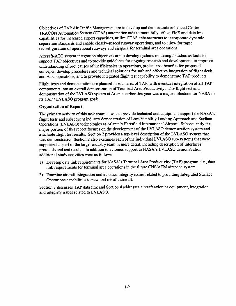
Theinitial testwasconductedOctober,1996,andutilizedtwoVHFtransmitterslocatedat two
separate sites; l) on the Hartsfield control tower, and 2) on top of the Renaissance Hotel located
directly to the North of the airport (see Figure 2-5 below J0r the location of both sites relative to the
airport layout). Using DGPS corrections inputs from separate DGPS base stations, both VIItransmitters transmitted this information at a one second rate. A van was equipped with two identical
VI-IF pallets, each containing a VHF broadcast receiver and a Collins GNR-4000 GPS receiver which
processed the DGPS correction outputs of the VHF data hnk to compute DGPS position. The GPS
receiver, in addition to providing DGPS position outputs at a one second rate, was modified to also
provide an indication of whether or not a DGPS data link message was received, and if so, whether the
CRC error correction code was successfully decoded indicating an error free message. A 24-bit CRCwas used based on an earlier version of the GPS ARINC Characteristic 743.
Taxi Routes
Airport surface coverage tests were performed by taxiing the airport surface while recording the
GPS position and data link status information. It was thus possible to plot data link status as a
function of location on the airport. Two distinct coverage routes were traversed in the coverage test:
1) ramp areas and the airport loop road surrounding the airport, and 2) all runways and taxiways. In
ramp areas, maximum line-of-sight (LOS) blockage areas were traversed to the greatest extent
possible to determine data link performance. These areas are primarily near the West walls of the
passenger terminal buildings. Figures 2-5 and 2-6 illustrate the two coverage routes. Taxi tests
were conducted during the night to gain access to the airport surface when traffic was low.
VHF Frequency Assignments
Two frequencies were assigned to the coverage test by the FAA; 118.2 MHz and 128.5 MHz. These
assignments were maintained for all tests conducted at Atlanta, with the control tower VHF
transmitter tuned to 128.5 MHz, which ultimately was used for VHF Traffic / AMASS holdbar data
link, and the Renaissance Hotel VHF transmitter tuned to 118.2 MI-Iz for VHF DGPS data link.
Antennas - Polarization and Placement
Both vertically and horizontally polarized antennas were tested to determine the effects of
polarization on surface coverage. Several types of antennas were used: 1) folded dipole
antennas that were oriented either vertically or horizontally (primarily at the control tower and
the hotel, 2) a magnet-mount whip antenna for the van, and 3) a turnstile antenna, consisting of
two crossed dipoles, for omnidirectional horizontal polari:e.ation.
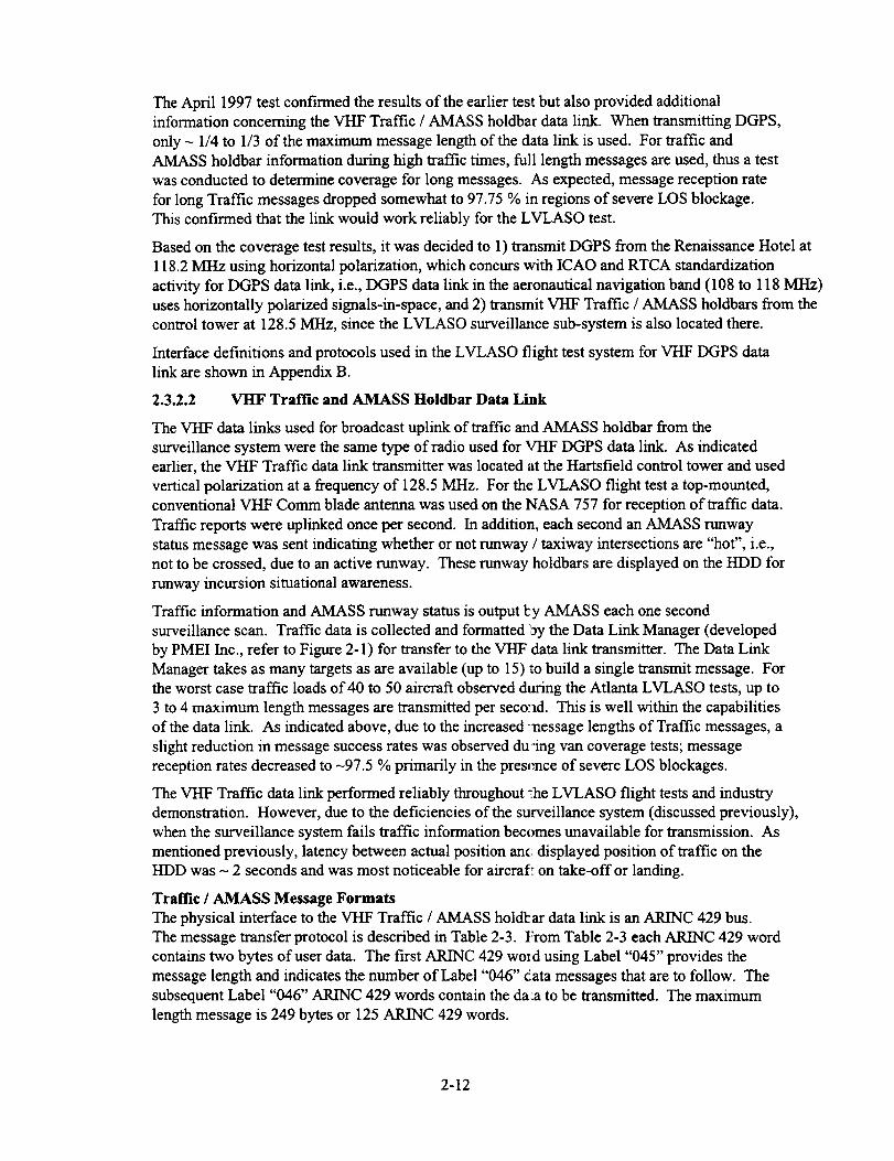
Figures 2-7 and 2-8 show antenna placement at the control tower and the Renaissance Hotel,
respectively. Since the control tower has four balconies CqW, NE, SE, SW comers), it was decided
to place a dipole antenna at each balcony to avoid any potential blockage effects to LOS by the
tower. Figure 2-7 shows one of the vertical dipole antennas pointing to the NW. The Renaissance
Hotel is visible to the North of the airport (visible just to the left of the dipole antenna). Figure 2-8
shows a vertical dipole pointed to the South from the hotel. During the actual LVLASO test withthe NASA 757, a horizontal turnstile antenna was used and was located closer to the SE comer of
the hotel roof. While antenna placement at the hotel was optimum for surface operations, it was not
ideal for terminal area operations. From Figure 2-8 it is aaparent that the additional -30 ft structure
seen to the North of the antenna on the hotel roof does provide some signal blockage, primarily
toward the NW direction. During flight tests with the NASA 757 in flight, some degradation in the
data link was observed in the NW comer of the terminal area and this is directly attributable to the
antenna siting. Flight test data link plots are shown later in this section.
2-8
Stouffer's
x
Figure 2-5 Coverage Test of Runways & Taxiways
(Control Tower using Vertical Polarization)
/
/'_."/
Tower
2-9
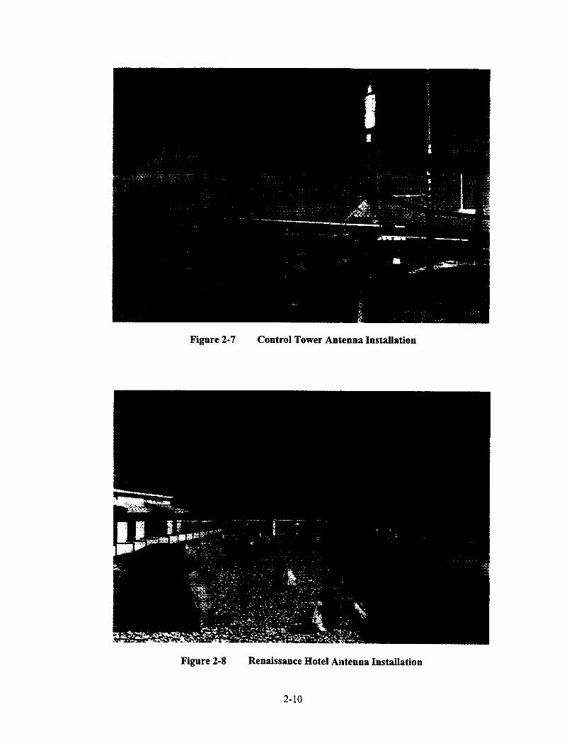
Figure 2-7 Control Tower Antenna Installation
Figure 2-8 Renaissance Hotel At, tenna Installation
2-10

DGPS Coverage Test Result Summary
The October 1996 VHF DGPS coverage test indicated that both the Control Tower and the
Renaissance Hotel each provided excellent coverage of the airport surface. Message reception rate
was excellent at - 99.75 % for all data link messages sent for all tests combined. There was no
difference in performance for vertical and horizontal polarization. The primary areas where some
messages were lost occurred along the West walls of the terminal buildings, which provide severe
LOS blockage and in the NW comer of the South half of the airport, again where terminal
buildings provide blockage. Some signals were also lost along the loop road, but these occurred in
regions where the loop road was at least 50 ft below the level of the airport surface itself. Tables
2-1 and 2-2 summarize performance results for the October coverage test. A complete description
of the coverage test results are provided in Appendix A, which contains a paper written for the
ICAO GNSS Panel describing the Atlanta DGPS coverage test.
Probability of correctly
receiving a single message Control Tower Stouffer's Hotel
per number of attempts
Single attempt 99.77% 99.73%
Two attempts 99.97% 99.94%
Three attempts 99.995% 99.968%
Four attempts 100% 99.986%
Five attempts 100% 99.995%
Six or more attempts 100% 100%
Table 2-1 Message Reception Probability vs Number of Transmission Attempts (van tests)
Control Tower Stouffer's Hotel
Vertical Polarization, 99.75 % coverage, 99.85 % coverage,
Ramp Area greatest difficulty on West side greatest difficulty betweenof Concourses C and D Concourses T, A, and B
Horizontal Polarization, 99.6 % coverage 99.5 % coverageRamp Area
Vertical Polarization,
Runways and Taxiways
Horizontal Polarization,
Runways and Taxiways
99.77 % coverage,
almost perfect coverage, a few
minor exceptions on NWcomer of South half
99.95 % coverage,
nearly perfect coverage
99.94 % coverage,
nearly perfect coverage
99.67 % coverage,
almost perfect coverage exceptNW comer of South half
Table 2-2 Qualitative Comparison of Transmit Site Performance (van tests)
2-11
The April 1997 test confirmed the results of the earlier test but also provided additional
information concerning the VHF Traffic / AMASS holdbar data link. When transmitting DGPS,
only - 1/4 to 1/3 of the maximum message length of the data link is used. For traffic and
AMASS holdbar information during high traffic times, full length messages are used, thus a test
was conducted to determine coverage for long messages. As expected, message reception rate
for long Traffic messages dropped somewhat to 97.75 % in regions of severe LOS blockage.
This confirmed that the link would work reliably for the LVLASO test.
Based on the coverage test results, it was decided to 1) transmit DGPS from the Renaissance Hotel at
118.2 MHz using horizontal polarization, which concurs with ICAO and RTCA standardization
activity for DGPS data link, i.e., DGPS data link in the aeronautical navigation band (108 to 118 MHz)
uses horizontally polarized signals-in-space, and 2) transmit VHF Traffic / AMASS holdbars from the
control tower at 128.5 MHz, since the LVLASO surveillance sub-system is also located there.
Interface definitions and protocols used in the LVLASO flight test system for VHF DGPS data
link are shown in Appendix B.
2.3.2.2 VHF Traffic and AMASS Holdbar Data Link
The VHF data links used for broadcast uplink of traffic and AMASS holdbar from the
surveillance system were the same type of radio used for VI-IF DGPS data link. As indicated
earlier, the VHF Traffic data link transmitter was located at the Hartsfield control tower and used
vertical polarization at a frequency of 128.5 MHz. For the LVLASO flight test a top-mounted,
conventional VHF Comm blade antenna was used on the NASA 757 for reception of traffic data.
Traffic reports were uplinked once per second. In addition, each second an AMASS runway
status message was sent indicating whether or not runway / taxiway intersections are "hot", i.e.,
not to be crossed, due to an active runway. These runway holdbars are displayed on the HDD for
runway incursion situational awareness.
Traffic information and AMASS runway status is output l:y AMASS each one second
surveillance scan. Traffic data is collected and formatted _y the Data Link Manager (developed
by PMEI Inc., refer to Figure 2-1) for transfer to the VHF data link transmitter. The Data Link
Manager takes as many targets as are available (up to 15) to build a single transmit message. For
the worst case traffic loads of 40 to 50 aircraft observed during the Atlanta LVLASO tests, up to
3 to 4 maximum length messages are transmitted per seco:ld. This is well within the capabilities
of the data link. As indicated above, due to the increased :nessage lengths of Traffic messages, a
slight reduction in message success rates was observed dudng van coverage tests; message
reception rates decreased to -97.5 % primarily in the preslmce of severe LOS blockages.
The VHF Traffic data link performed reliably throughout :he LVLASO flight tests and industry
demonstration. However, due to the deficiencies of the surveillance system (discussed previously),
when the surveillance system fails traffic information becomes unavailable for transmission. As
mentioned previously, latency between actual position anci displayed position of traffic on the
HDD was - 2 seconds and was most noticeable for aircrafl: on take-off or landing.
Traffic / AMASS Message Formats
The physical interface to the VHF Traffic / AMASS holdl:ar data link is an ARINC 429 bus.
The message transfer protocol is described in Table 2-3. From Table 2-3 each ARINC 429 word
contains two bytes of user data. The first ARINC 429 word using Label "045" provides the
message length and indicates the number of Label "046" data messages that are to follow. The
subsequent Label "046" ARINC 429 words contain the daia to be transmitted. The maximum
length message is 249 bytes or 125 ARINC 429 words.
2-12

Tx
Seq
N/A
32
Parity
1 Parity
2 Parity
3 Parity
4 Parity
31 30 29 ........................... 2221 ............................. 14 13..11 109
SSM Spare (3 bits) 1 Data Block Length (13 bits) SSID SDI
SSM 2 "nTransmitted Byte I a Transmitted Byte SSID SDI
SSM 40` Transmitted Byte 3 _dTransmitted Byte SSID SDI
SSM 6 th Transmitted Byte 5 tb Transmitted Byte SSID SD!
SSM 8 th Transmitted Byte 7 th Transmitted Byte SSID SDI
........ 1
Label 045
(start)
Label 046
Label 046
Label 046
Label 046
Label 046
Label 046
n Parity SSM 8 pad bits if odd # of bytes in block
or Parity SSM Last Transmitted Byten
Last Transmitted Byte SSID SD1
(n-I) Transmitted Byte SSID SDI
Table 2-3 ARINC 429 Message Input Interface to VHF Data Links
Two types of Traffic / AMASS holdbar messages are sent via VHF data link:
1. Airport Status Message
2. Target Information Message
The airport status message is shown in Table 2-4 and consists primarily of the AMASS holdbar
information. Holdbar encoding is shown in Table 2-5 and shows that there are 44 runway / taxiway
intersections at the Hartsfield airport. This message is sent during each one second surveillance scan
and was used by the NASA 757 to initiate a traffic display scan for the HDD. When a runway is
active and should not be entered, the holdbar is activated (and displayed in "red" on the NASA 757
HDD). The airport status message also has provisions for wind speed, wind direction, and runway
visual range (RVR) information, although this information was not used in the LVLASO flight test.
order of transmission: first byte _ last byte
Data Field Name Description Valid Range for Data Type Interpretation
T Message Type 4 bits ("nibble"), unsigned [1 ] Value is 1 for this message type
0 unused 4 bits ("nibble"), unsigned [0] unused, always 0
A4A3A2AI Runway 8L/26R 32 bits, bit map all (bit map) I=ON, 0=OFF (see Table 2-5)
B4B3B2B1 Runway 8R/26L 32 bits, bit map all (bit map) I=ON, 0----OFF (see Table 2-5)
C4C3C2C1 Runway 9L/27R 32 bits, bit map all (bit map) I=ON, 0=OFF (see Table 2-5)
D4D3D2DI Runway 9R/27L 32 bits, bit map all (bit map) I=ON, 0--OFF (see Table 2-5)
SS Wind Speed 1 byte, unsigned BYTE [0-254] knots
or [255] or FF Hex information unavailable
H2H1 Wind Direction 2 bytes, unsigned WORD [0-359] degrees
or [65535] or FFFF Hex information unavailable
R2R1 RVR 2 bytes, unsigned WORD [0-65534] feet
or [65535] or FFFF Hex information unavailable
Byte #
I
I
2-5
6-9
I0-13
14-17
18
19-20
21-22
Table 2-4 Airport Status Message Format
2-13

Runway 8L/26R
(11 intersections)
Bit 0:
Bit 1:
Bit 2:
Bit 3:
Bit 4: D, D
Bit 5: C, CBit 6:B5
Bit 7:A4
Bit 8:B3
Bit 9:B1
Bit 10: H, ABit 11-31: 0-filled
Runway 8R/26L
(10 intersections)
E,BEl3
Eli, B10
D, D
B15, A Bit 0:
B13 Bit 1:
B 11, A6 Bit 2:B7 Bit 3:
Bit 4: C, CBit 5:E7
Bit 6: E5, B6
Bit 7: E3, B4
Bit 8: El, B2
Bit 9: H, HBit 10-31: 0-filled
Runway 9L/27R
(15 intersections)
Bit 0: M
Bit 1:M20
Bit 2:M18
Bit 3:M16
Bit 4: J, J
Bit 5: K, D
Bit 6: D, D
Bit 7: S, SBit 8:M12
Bit 9:M10
Bit 10:M6
Bit 11:M4
Bit 12: T, TBit 13:M2
Bit 14: P, LBit 15-31: 0-filled
Runway 9R/27L
(8 intersections)
Bit 0:N12
Bit 1: J
Bit 2: K, K
Bit 3: R, N10Bit 4:N6
Bit 5:N4
Bit 6:N2
Bit 7: P
Bit 8-31: 0-filled
Table 2-5 Holdbar Bit Map (Atlanta Hartsfield Runway Layout)
The second message type consists of target information. The target information message format
is shown if Table 2-6. Message fields consist of the message type, flight number address (eight
ASCII characters), and 32-bits latitude and longitude for _ircraft position. Thus for a single
aircraft, 16 bytes of data are required. The maximum number of targets stored in one message is
therefore 15 aircraft. During peak traffic times, the data link was required to transmit as many as
3 full-length messages per second, which is well within the data link capacity. A 31.5 kbps
D8PSK VHF broadcast data link should be able to suppol7. -240 aircraft using the message
encoding used in the LVLASO flight test.
B_e#
]
1
2-9
10-13
14-17
Data Field
TO A0...A7 L0...L3 E0...E3 ... A0...A7 L0...L3 E0...E3
order of transmission: firstb
Name Description
Cte =_ last byte
Valic_ Range for Data Type Interpretation
[2] value is 2 for this message type
[0] unused, always 0
flight number
(null or spaces if unknown)
[+/- 89.99...] degrees, WGS-84, North is positive
T Message Type 4 bits ("nibble"), unsigned
0 unused 4 bits ("nibble"), unsigned
A7 - A0 1a address 8 ASCII characters
L3 - L0 I _ target latitude 32 bits, FLOAT
E3 - E0 32 bits, FLOAT1_ target longitude [0.0 - 359.99...] degrees, WGS-84, East is positive
A7 - A0 n tb address 8 ASCII characters
L3 - L0 n tb target latitude 32 bits, FLOAT
E3 - E0 n '_ target longitude 32 bits, FLOAT
Table 2-6
flight number
[+/- 89.99...] degrees, WGS-84, North is positive
[0.0 - 359.99...] degrees, WGS-84, East is positive
Target Information Message Format
2-14

Ontheaircraftside,theoutputinterfacefromtheVHFdatalink receiverto the aircraft I/O
network (Figure 2-3) is an ARINC 429 output bus. The file transfer protocol of received Traffic
/ AMASS holdbar data is the same shown in Table 2-3, using Label "045" and "046" ARINC
429 words, each carrying two bytes of data.
2.3.2.3 LVLASO Flight Test VHF Data Link Performance (DGPS)
Data link performance was characterized for the VHF DGPS data link aboard the NASA 757
aircraft by recording DGPS position and data link message status outputs from the GNR-4000
GPS sensor, and also recording received signal strength outputs based on internal receiver
Automatic Gain Control (AGC) information from the VHF DGPS data link receiver. Three states
of message status were recorded; 1) no message received, 2) message received but CRC failed,
and 3) message received and CRC passed successfully indicating a correctly received message.
To facilitate interpretation of flight test results, a Jeppesen chart of the Hartsfield airport layout
is provided in Figure 2-9. Figures 2-10 through 2-15 are six representative VHF DGPS data link
performance plots, depicting the path traversed by the NASA 757 during a particular flight test,
the signal strength (color coded) and providing an indication of message failures (indicated by
larger, color-coded squares). Color coding is as follows:
1. Red signal strength _<- 87 dBm
2. Yellow signal strength -77 dBm to -87 dBm
3. Green signal strength -67 dBm to -77 dBm
4. White signal strength > -67 dBm.
Larger "blue squares" indicate that received messages were garbled (failed CRC) and larger
"magenta squares" indicate messages were not received (recall that messages are sent at a one
per second rate).
Two items of note in examining VHF DGPS data link results from the LVLASO flight tests are
the received signal strength and message loss events. With respect to signal strength, our
primary focus was to ensure proper signal coverage for the LVLASO flight tests. Earlier van
tests provided an indication that signal coverage was excellent for surface operations and
expectations were for continued excellent terminal area coverage for the NASA 757. In terms of
signal coverage, our objectives were met exceedingly well throughout all the flight tests for both
VI-IF data links. The only significant exception occurs in the NW comer of the terminal area,
beyond 5 nmi range, where it is evident that signal blockage due to the additional building
structure atop the Renaissance Hotel plays a significant role (see Figure 2-8).
Figures 2-10 and 2-11 illustrate two flight tests where the NASA 757 performed a flight, with
takeoff on runway 26L and a loop to the NW and subsequent downwind leg, and then turning
South to intercept the Localizer for approach and landing on runway 26 R. In Figure 2-10, the
aircraft did an immediate turn toward the downwind leg, and thus the signal level remained
strong as indicated by the 'white" trace throughout the West portion of the flight path. Even
during the downwind leg that extended - 13 nmi beyond the location of the DGPS base station
and VI-IF Transmitter site (Renaissance Hotel), the signal remained quite strong and no message
failures occurred. In Figure 2-11, the NASA 757 did a more gradual climb and turn and went -8nmi to the WNW before turning downwind. The signal level dropped severely and some
messages were garbled or lost. Signal level improved substantially on the downwind leg. Some
signal degradation again occurred during the South leg and Localizer capture portion of the
flight, but not as severe. The degradation in the NW comer of the flight path is the direct result
of some signal blockage due to antenna siting of the DGPS data link indicated above.
2-15

Figure 2-9 Jeppesen Chart of Atlav ta Hartsfieid Airport
2-16

Figures 2-12 and 2-13 illustrate data link flight test results when the NASA 757 conducted takeoff
on 8R and flew a downwind leg to return on 8L. The effect of antenna blockage is very evident to
the WNW in the pattern, where numerous messages were either garbled or lost entirely beyond 5
umi range. Figure 2-12 shows the worst case results observed throughout the flight tests. Once
the antenna blockage is no longer a factor, signal strength is very good throughout the flight with
no additional messages failures. Figure 2-13 provides another perspective of a similar flight test,
with a bit more signal degradation evident in the NE corner compared to Figure 2-12.
Figures 2-14 and 2-15 provide flight test data on scenarios that did not include flight. The aircraft
was based at the Mercury Air Center to the North of the airport. In Figure 2-14 the NASA 757
taxied via taxiways Alpha, Dixie, and Echo for a simulated takeoff on 26L. The aircraft then
performed a high-speed ROTO with exit on Echo 3 and return taxi to Mercury Air via Echo,
Charlie and Alpha. As expected, the signal level was very strong throughout the scenario as
indicated by the white Irate. A few messages were actually lost and are attributed to multipath as a
result of the large Delta hangars on the SE corner of the North runway area. Figure 2-14 illustrates
a taxi scenario to the South half of the airport. Again signal levels were strong except in a few
areas along the taxiway directly South of the terminal buildings, where some signal blockages are
observed. Only a couple messages were not received correctly throughout the flight test scenario.
Table 2-7 summarizes the message reception performance of the VHF DGPS data link for flight tests
with the NASA 757. Data collected for both taxi and airborne tests resulted in -99.8 messages
reception probability. (27 errors in 15792 messages for taxi, 76 errors in 37681 messages for airborne
flight tests). Taxi message failures occurred only as single error events. For airborne flight tests one
triple error event and 3 double error events occurred, with all other message failures being single events.
Message failures in the NW corner were excluded since they are clearly due to line-of-sight blockage
effects due to the hotel. Even when counting the message failures in the NW corner (with suboptimal
antenna siting), the message reception probability is 99.2%.
The few message losses that did occur were in the vicinity of the following regions: 1) in the vicinity of
the Mercury Air (AS) / Taxiway A intersection (multipath), 2) in front of the Delta Hangar to the Southeast
of runway 8R/26L (multipath), 3) on the South half of the airport when the line-of-sight is blocked by
terminal buildings (particularly Terminal E), 4) for a brief instant at the time the NASA 757 rotated when
executing some of the takeoffs on runway 8R (multipath and/or aircraft antenna null), 5) a few occasions in
the ENE corner during flight, and 6) the NW corner due to line-of-sight blockage effects by the hotel.
Probability of correctly Taxi only tests Airborne tests Total all flight tests
receiving a single message (15792 messages) (37681 messages) (53473 messages)per number of attempts
Single attempt 99.83% 99.80% 99.81%
Two attempts 100% 99.992 99.994%
Three attempts 100% 99.997% 99.998%
Table 2-7 Message Reception Probability vs Number of Transmission Attempts (757 tests)
The VHF Traffic / AMASS holdbar data link was not characterized in detail but also provided reliable
coverage throughout all flight tests. As indicated previously, traffic messages are somewhat more
vulnerable due to increased message length (Recall that van tests indicated - 99.75 % and -97.5 %
message reception rates for DGPS and Traffic / AMASS, respectively. Refer to Sections 2.3.2.1 and
2.3.2.2). The traffic / AMASS holdbar application did not utilize a CRC for error detection. However,
reasonableness checks on message length and various message fields were made to reject erroneous
traffic reports to minimize display of misleading information to the pilot via the HDD.
2-17

Figure 2-10 Flight Test Scenario # 1 - Takeoffon 26L, Downwind Leg, Landing on 26R
2-18
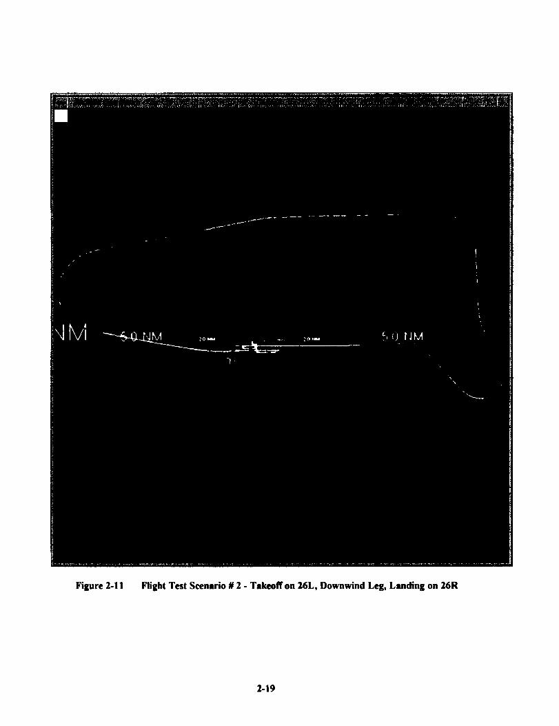
Figure2-11 FlightTestScenario# 2 - Takeoffon 26L, Downwind Leg, Landing on 26R
2-19

Figure2-12 FlightTestSceurio# 3 - Takeoff on tR, Downwind Leg, Landing on 8L
2-20

Figure2-13 FlightTestScenario# 4 - Tsdueoff on 8R, Downwind Leg, Landing on 8L
2-2!

Figure2-14 FlightTestSceurio # 5 - Taxi-Omly Scenario with High-Speed ROTO
(Leave Mercury Air; taxi via Alpha, Dixie, Echo to 26L; simulate takeoff and perform high-
speed ROTO with exit on Echo 3; taxi back to Mercury Air via Echo, Charlhie and AIpho)
2-22

Figure2-15 FlightTestScenarie#6 - Taxi-OnlyScenariowithHigh-SpeedROTO(LeaveMercuryAir; taxiviaAlpha,l)ixk, Julietto 27L; simulate takeoff and perform high-
speed ROTO with exit on November 4; taxi back to Mercury Air via November, Papa, Lima,
Dixie and Alpha)
2-23

2.3.3 Mode-SData Link
The MOde-S link was utilized for LVLASO Controller Pilot Data Link Communications (CPDLC)
and also provided ADS-B extended squitters for surveillance. The Mode-S link consists of ATIDS
R/Ts (uplink on 1030 MHz) on the ground and the Mode-S transponder and associated ADLP
onboard the NASA 757 aircraft. The Mode-S transponder / ADLP provides the Mode-S Specific
Services (MSSS) protocols needed for addressed CPDLC communications and broadcast ADS-B.
2.3.3.1 CPDLC Data Link
Controller - pilot data link communications for LVLASO were conducted as follows; 1) a test
controller repeats actual ATC communications to the NASA 757 aircraft to convert the message
into a data link message, 2) the data link message is encoded using RTCA DO-219 message
encoding, using existing messages when possible, but also required development of new messages
when not available, 3) encoded messages are sent to the ATIDS master workstation (see Figure 2-
2) via modem for further encoding to MSSS protocol and subsequent transmission via 1030 MHz,
4) the NASA 757 Mode-S transponder receives the uplink message, decodes it (sending a
transponder reply to acknowledge receipt of the interrogation) and provides it to the I/O network
and flight computer for display on the HDD to the flight crew, 5) the flight crew acknowledges
the message using the pilot interface device (PID), which encodes a downlink message via the
Mode-S transponder/ADLP using DO-219 and MSSS pro:ocols (1090 MHz downlink).
Note: Message retry protocols were implemented in the event a data link message collided with
another transmission on the MOde-S link, which is entire1/possible due to the random access
protocol used by the Mode-S link. In addition, controller messages were highlighted to the
controller when acknowledgments occurred. Failure to receive acknowledgments were thus
immediately evident to the ATC controller.
Table 2-8 summarizes the CPDLC messages used in the I VLASO flight test.
LVLASO Uplink Messages
Element ID Message
117 Contact [icaoname] [frequency]
120 Monitor [icaoname][frequer cy]
200 Hold Short [position]
212 Taxi [runway] Via [route]
219 Taxi [ramp] Via [route]
220 Cross [position] [without delay]221 Continue Taxi
223 Taxi Into Position and Hold
224 Cleared For Takeoff
LVLASO Downlink Messages
1 Roger3 Unable
202 Taxiway Deviation
203 Turned-off on Taxiway [#]
204 Taxiway Deviation Resolved
Table 2-8 LVLASO CPDLC Messages
2-24

Twomethodsof repeatingand convening ATC voice messages to data link messages were
demonstrated by the test controller: 1) Aural repetition of actual ATC messages using a Verbex
voice recognition unit to digitized the message; 2) touch screen input to enter the data link
message. In both cases, the digital message is encoded using DO-219 encoding.
The Controller Interface voice recognition system requires training to the controllers voice. After
initial adjustments to voice recognition, and reducing the vocabulary to a subset specific to the
Atlanta airport, voice recognition provided -98 % recognition of all messages. It was evident that
voice recognition is preferable over touch screen input due to controller workload. CPDLC raises
significant issues in both the ATC cab and the flight deck in terms of human factors, workload and
maintaining the man-machine interface information flow, which will require further research by
industry. The Controller Interface described above was developed by St. Cloud St. University.
The physical Mode-S data link itself worked as expected, but was at times adversely effect byATIDS master work station failures.
2.3.3.2 ADS-B
The NASA 757 aircraft reliably transmitted ADS-B extended squitters at a 0.5 second update
rate. ADS-B squitters provided aircraft position with DGPS accuracies. ATIDS surveillance of
ADS-B reports is superior to multilateration surveillance, since reception of the signal by just
one ATIDS RJT allows tracking of the aircraft (versus reception by multiple R/Ts for
multilateration).
Figures 2-16 and 2-17 illustrate sample plots for ADS-B surveillance of the NASA 757 aircraft
that were recorded. Figure 2-16 represents ADS=B surveillance for a taxi test to the South half
of the airport (similar to the Figure 2-15 scenario). From Figure 2-16, obvious LOS outages are
observed whenever the NASA 757 taxied near a terminal building (refer to Figure 2-9 for layout
of airport). The outages are simply explained by the fact that the 5 ATIDS R/Ts are deployed
only on the North half of the airport and thus did not provide LOS to the regions blocked in the
South half. The problem would be easily corrected by proper deployment of ATIDS R/Ts to
include the South half of the airport. With the exception of the blockage regions, ADS-Bsurveillance on the NASA 757 was reliable.
-7(
r_no
O0
4000
3000
2000
1000
I I t _ I i 0
-6000 -5000 -4000 -3000 -2000 -lOOqooo_
-2000
-4NNN
10 30
- - _,,_2000
INORm ]
30 feet
Figure 2-16 NASA 757 ADS-B Surveillance Coverage - Taxi Scenario
2-25
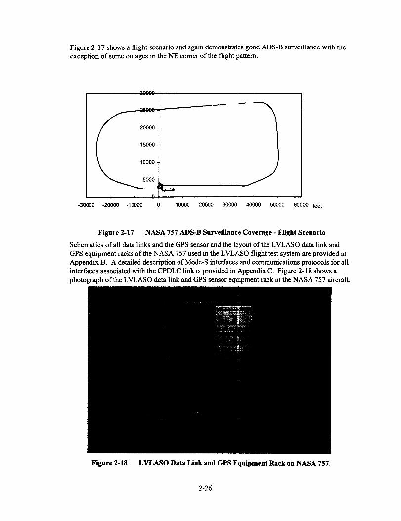
Figure2-17 shows a flight scenario and again demonstrates good ADS-B surveillance with the
exception of some outages in the NE comer of the flight pattern.
2_333-
20000
15000
._ 10000
-30000 -20000 -10000 0 10000 20000 30000 40000 50000 60000 feet
Figure 2-17 NASA 757 ADS-B Surveillance Coverage - Flight Scenario
Schematics of all data links and the GPS sensor and the l_yout of the LVLASO data link and
GPS equipment racks of the NASA 757 used in the LVLASO flight test system are provided inAppendix B. A detailed description of Mode-S interfaces and communications protocols for all
interfaces associated with the CPDLC link is provided in Appendix C. Figure 2-18 shows a
photograph of the LVLASO data link and GPS sensor equipment rack in the NASA 757 aircraft.
Figure 2-18 LVLASO Data Link and GPS Equipment Rack on NASA 757.
2-26

3. Terminal Area Productivity (TAP) Data Link
3.1 Introduction
This section of the report examines the issues concerning the future direction of aeronautical data
link communications as they pertain to TAP data link and the future Communication Navigation
Surveillance (CNS) / Air Traffic Management (ATM) system that is currently being addressed
within the industry. Since the majority of TAP data link applications are also utilized outside
terminal area airspace, the approach taken here is to examine the overall CNS/ATM data link
environment in developing candidate avionics data link architectures, and then mapping theseresults back to TAP data link.
Several data link technologies will play an important role in providing the needed capabilities for
the future CNS/ATM and TAP data link system, each providing specific services that are best
suited to that particular technology. Data link technologies are VHF, Mode-S, HF, and SATCOM
data link. While SATCOM and HF data link have clearly defined roles in the future CNS/ATM
data link system (i.e., providing data link coverage in oceanic and remote-area enroute regions,
the role of VHF and Mode-S data link is considerably less clear. It is the VHF and Mode-S data
links that have the greatest impact on future TAP data link.
At present, two distinct VI-IF data link approaches are currently being developed within the industry
that are central to the future direction of the CNS/ATM and TAP data link system. This report
provides considerable focus on these approaches and develops candidate data link architectures
(from an avionics perspective) in meeting future CNS/ATM and TAP data link requirements.
The two VHF data link approaches that affect the direction of CNS/ATM data link are as follows:
1) Transition from today's VHF ACARS data link (also referred to as VHF Data Link {VDL}
Mode 1) to a higher data rate VDL Mode 2 and subsequently to VDL Mode 3, which
provides the capability for multiple, simultaneous digital voice and data services on a single
25 KHz VHF frequency channel.
2) Self-Organizing TDMA (STDMA) also referred to as VDL Mode 4.
Both of these VHF data link approaches are vying to provide a range of data link applications
and services, some of which are in direct competition with one another, while others may be
more synergistic. The VDL Mode 1, 2, and 3 transition approach is primarily intended to
address the conventional communications services of Air Traffic Services, consisting of Air
Traffic Control (ATC) data link and Air Traffic Services (ATS) such as flight information
services, and Airline Operational Communications (AOC) and Airline Administrative
Communications (AAC). These data link applications are primarily strategic in nature, many of
which would be sent via the Aeronautical Telecommunications Network (ATN).
VDL Mode 4 (i.e., STDMA) is envisioned by its proponents to provide a wide range of data link
applications from tactical, broadcast communications such as Automatic Dependent Surveillance
(ADS-B) and Differential GPS (DGPS or DGNSS) corrections uplink, to tactical non-ATN ground-to-
air and air-to-air services, and the more strategic ATC/ATS and AOC/AAC services indicated above.
Section 3.2 provides an overview of future CNS/ATM data link applications that are currently
being planned the role of the Aeronautical Telecommunications Network (ATN) in providing
these applications, and provides summaries of the various data links candidates that will likely
implement these applications. Emphasis will be on the evolution of the two VHF data link
approaches indicated above (VDL Modes 1, 2, and 3 and VHF STDMA / VDL Mode 4) andMode-S data link.
3-1

Section 3.3 provides a brief description of each of the CNS/ATM data link applications and their role
in TAP data link. A more detailed description of VHF data link candidates is provided as an appendix
(Appendix D in Volume II of report) in support of developing data link architectures. Section 3.4
discusses candidate mappings of data link applications to data link architectures / implementation
approaches, while Section 3.5 examines viable CNS/ATM data link architectures from an avionics
equipment perspective. Section 3.6 summarizes conclusions from the viewpoint of TAP data link.
3.2 Aeronautical Data Link Overview
3.2.1 Future CNS/ATM Data Link System
While the current National Airspace System ('bIAS) relies almost entirely on analog voice
communications for Air Traffic Services (ATS) via VHF radio and uses ACARS data link for
AOC, AAC and some limited ATS data link services, it is expected that the use of data link will
greatly expand and play a vital role in the future CNS/AIM system.
The future CNS/ATM system will rely on global satellite navigation, ground-based and satellite-
based communications via the Aeronautical Telecommunications Network (ATN), and on
Automatic Dependent Surveillance (ADS and ADS-B) to bring about needed improvements in
efficiency and safety of operations to address the problems associated with increasing levels of
air traffic. Data link will be an integral part of the future CNS/ATM system and the systems thatsupport TAP for ATS/ATC communications, ADS-B sur.,eillance, augmentation to GPS for
precision approaches and enhanced navigation, support or'automation functions both ground-
based and in the aircraft to allow 4-D navigation, route nc:gotiation and reduced separation (i.e.,
free flight), and numerous other flight services and traffic services applications. While there will
always be a need for voice communication, its use is expected to decline over time for delivery
of more infrequent, non-routine messages and as backup for data link. Data link is expected to
provide the majority of routine, standard ATC communications.
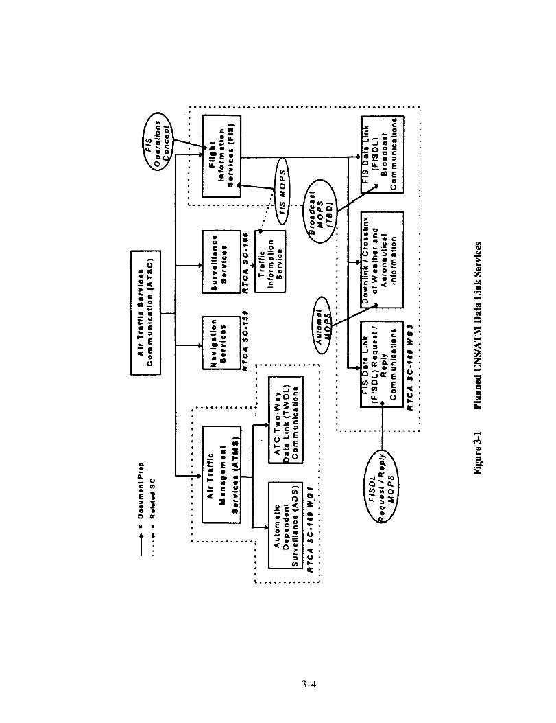
Figure 3-1 provides a breakdown of data link applicatiom (services) planned for the future
CNS/ATM system and identifies the RTCA subcommittees that are developing standards.
Individual data link applications are listed in Table 3-1. These applications pose different
communications requirements in terms of latency (strate_ ic versus tactical), addressed versus
broadcast, coverage (enroute, terminal area, surface, oceanic enroute or remote areas), capacity,
integrity, availability, and quality of service, i.e., Required Communication Performance (RCP).
A commonly accepted view of the end-state CNS/ATM data link system which addresses many
of these requirement is illustrated in Figure 3-2. Each of the data link applications shown inTable 3-1 is described in more detail in Section 3.3.
As shown in Figure 3-2 the Aeronautical Telecommunications Network plays a fundamental role
in the future CNS/ATM data link system, providing point-to-point (i.e., addressed) connectivity
between ground and airborne end-user systems. A number of physical data links and sub-
networks are interconnected by ATN. The future CNS/ATM data link system utilizes VHF,
SATCOM, I-IF and Mode-S data links to satisfy the diver:,e communications requirements (RCP)
of end-user applications. SATCOM and HF data link provide services primarily in remote and
oceanic enroute areas where terrestrial VHF and/or Mode-S cannot be employed.
Data link communications via the ATN are strategic in nature and have moderate to high latencies.
Some CNS/ATM communications require tactical commv, nications and will rely on specific (non-
ATN) communications, e.g., Mode-S Specific Services (blSSS) or VHF Specific Services (VSS). In
addition to addressed communications, broadcast services play a vital role in the future CNS/ATM
3-2

datalink system(e.g.,ADS-B, DGPS/DGNSS, FIS-B). Since the ATN does not support broadcast
communications, broadcast data link are typically provided by specific, non-networked services.
SATCOM and HF data links shown in Figure 3-2 are indicated for reference only. The focus of this
paper is on VHF data link (VDL) and the CNS/ATM data link applications that are most appropriately
allocated to VDL. Mode-S enters into the discussion for ADS-B and perhaps tactical ground-to-air
and air-to-air communications, where both Mode-S and VDL specific services are viable candidates.
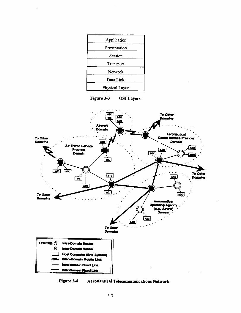
3.2.2 Aeronautical Telecommunications Network (ATN)
As indicated in the previous section, the ATN provides the interconnectivity of the various
CNS/ATM sub-networks to allow point-to-point communications among end-users. The ATN
accomplishes this intercormectivity and routing of information by using the Open Systems
Interconnect (OSI) layered communications protocols shown in Figure 3-3. The ATN routing
architecture indicating connectivity among the various end-user domains is illustrated in Figure 3-4.
Figure 3-3 shows the 70SI layers that provide various services for the end user, which is
represented by the application layer. The top four layers of the OSI stack (i.e., application,
presentation session, and transport layers) are referred to as the "upper layers" and are defined inARINC 637 and ARINC 638 for aeronautical data link communications. The actual ATN router
function is provided by the upper portion of the network layer.
The physical, data link and network layers are referred to as the "'lower layers". While the
physical and data link layers may be different for various aeronautical sub-networks, a common
sub-network interface is defined for all aeronautical data link communications, which allows
ATN interconnectivity via the router. The common subnetwork layer interface to the
aeronautical sub-networks and lower layers is specified by the ISO 8208 protocol.
It is in the lower layers where the various VDL modes utilize different techniques and protocols
(i.e., upper layers are the same, regardless of VDL mode). The differences in the "lower layers" for
the various VDL modes are described in Appendix D.
Due to the multiple protocol layers, ATN communications typically require moderate to high
transfer delays and thus are more appropriate for strategic communications. Low-latency,tactical communications should be conducted outside of the ATN. For non-ATN
communications, the upper layers are bypassed, with typically only physical layer, data link
layer and perhaps network layer services being used to provide specific services for local
coverage and tactical communications. The VDL Mode 1, 2 and 3 transition plan is intended to
address strategic communications and no VHF specific services (VSS) are currently being
defined. VDL Mode 4 and Mode-S are currently the only available candidate data links that
have VSS and Mode-S specific service (MSSS) capability.
3.2.3 Overview of VHF Data Link (VDL)
3.2.3.1 ACARS VDL Mode 1
Historically, the initial aeronautical data link capability was provided via ACARS data link (i.e.,
VDL Mode 1) over a conventional ARINC 716 AM voice radio for Out-Of-On-In (OOOI) data
link reporting of aircraft operations using a character-oriented protocol (ARINC 618). ACARS
data link use has expanded to include a range of AOC and AAC communications (e.g.,
maintenance reports, engine performance monitoring, flight data, etc.) and also includes some
limited ATS communications (e.g., predeparture clearance, oceanic clearance, and Automatic
Terminal Information Services {ATIS}).
3-3
c.v
m
ol..u<
u;E__• C
b =
_E
Uc t_
0 •
m I
°--.+°+.Q.°.°.o..oo..°°----°° ,..°.Ole.......°.°.
v m _ ,--
_b_ g m
............... 1_1.. _o_1 I_,• -- _/. I_ .
• "1_7 _J: I'._1•"- o"I-_-I . I I_-=_1_ _._1 . I-_. = E I_ _[ I."'-ol ' I I'EeOo I
=- 2 I'-_"l , I _-,=1
O* I,
ill i_ - I IIi _ II
z- i" ......... L i_ ._c "'" o _.,,,. E
..._,. El _il_ _ 0
i-c__ .......O-aE
: _ _ _1 _.E• II •---_ ..- _
, " c v, _._i i _ ,
: I'I0 i =
4D
' i
i.
i....
+im
l, ll4
,.4oi,Illil
+l,+.ll
3-4

CNS/ATM Data LinkType of Service Candidate Data Links
Application
CPDLC
(Controller Pilot Data Link
Communications)
RTCA DO-219
ADS-A (ADS-C)Automatic DependentSurveillance - Addressed or
Contract
RTCA DO-212, ARINC 745
ADS-B
(RTCA SC- 186 MASPS),
Data link for numerous
surveillance and separation
assurance end-user applications
(e.g., CDTI, parallel runway
approaches, entrail climb, etc.)
DGPS/DGNSS
(DGPS corrections uplink)
RTCA SC-159 MASPS and
ICAO GNSSP SARPS
FIS and FIS-B
(Flight Information Services)
- Predeparture clearance
- Digital ATIS,
- TWIP (terminal weather)
- ETRR (taxi ramp route)
- etc.,
Air Traffic Services (ATS) for
Air Traffic Control (ATC),addressed data link via ATN,
currently only strategic comms
(i.e., moderate latencies)
ATS/ATC addressed
communications via ATN,
strategic (i.e., moderate
latencies)
broadcast data link,
tactical (i.e., low latency
communications)
broadcast data link,
tactical (i.e., low latency
communications)
addressed and broadcast
communications
VHF, SATCOM, and HFdata links
VHF, SATCOM, and HFdata links
Mode-S or VHF data link
VHF data link,
(D8PSK or GFSK
modulation)
VHF data link
TIS and TIS-B broadcast data link Mode-S or VHF data link
(Traffic Information Services)
AOC/AAC
(airline operational andadministrative
communications)
addressed communications via
ATN
strategic (moderate latencies)
addressed communications,
primarily tactical and some
strategic communications
Air-Air Communications
- e.g., trajectory negotiation,- collision avoidance crosslink
VHF, SATCOM, and HFdata links
Mode-S crosslink (e.g.,collision avoidance
crosslink) or VHF data link
Table 3-1 Planned CNS/ATM Data Link Applications
3-5

I Aee I ! - 11
IITNIIOUIER[DIN-IIOO]
|DI,III|
imlBl.llJllPlllP-Olo!
llOIE.IDailh_l'IFl-O01]
ir,ll ROUITR
,In'SGmmutmmmll tldl-IIImwk
Figure 3-2 CNS/ATM Data Link System
To support future compatibility with ATN, the character-oriented protocol is being upgraded and
replaced with code/byte independent binary-oriented protocols (BOP). The ACARS ARINC 618
protocol is thus being upgraded to the Aviation Packet Comm_mication (AVPAC) bit-oriented
protocols (ARINC 631), which defines the lower 3 layers oft_e OSI stack (Figure 3-3) for VDL.
For VDL Mode I, the physical layer uses 2400 bps Minimum ghift Keying (MSK) modulation
which then modulates the AM carrier. The media access chanlel (MAC) layer, which is the
lower layer of the data link layer, uses Carrier Sense Multiple _,ccess (CSMA) p-persistent
protocol to determine channel access for data link message exchange.
3-6
Application
Presentation
Session
Transport
Network
Data Link
Physical Layer
Figure 3-3 OSI Layers
o
Tol_ha" ....
@ m,..ll,,,,i,i,i,n, N
_ / I.ill H
_ Fired Liill H
_ Fllld IJlli
Figure 3-4 Aeronautical Telecommunications Network
3-7

VHF Frequency Congestion Problem
The use of VHF data link is expected to increase substantially in the future CNS/ATM system.
At the same time, as air traffic levels continue to increase, some regions in the world are already
experiencing shortages in the available number of VHF communications frequencies. This
problem is expected to continue to become more severe and Europe has already mandated
implementation of 8.33 KHz channels for VHF analog voice communications to alleviate
frequency congestion.
In order to provide higher data rates and to provide more efficient use of available frequencies,
i.e., more bits per Hz of bandwidth, industry has arrived at two, distinct VDL approaches. As
indicated earlier, the FAA and Mitre have developed a transition plan from VDL Mode 1 to
Modes 2 and 3, while Sweden has developed an entirely new VDL approach based on self-
organizing TDMA (STDMA) also called VDL Mode 4.
The next sections provides summary descriptions of VDI, Modes 2, 3 and 4, which providesubstantially more system capacity than the current VHF ACARS (VDL Mode 1 system). This
information is later used in developing data link allocations between CNS/ATM and TAP data
link applications and individual data links.
3.2.3.2 Summary of VDL Mode 2
VDL Mode 2 is a data-only data link (i.e., no digital voice capability) that provides an order of
magnitude increase in channel capacity versus VDL Mod:_ 1 (ACARS). The increase in capacity
is the direct result of the 31.5 kbps D8PSK waveform (versus the 2400 bps MSK waveform used
by VDL Mode 1). DSPSK requires a DFU of 16 to 20 dB (compared to 14 dB for analog voice),
which influences frequency reuse. Like VDL Mode 1, VI)L Mode 2 uses Carrier Sense Multiple
Access (CSMA) channel access protocol. In addition, VDL Mode 2 uses the bit-oriented
protocol (versus character-oriented protocol of ACARS) that provides compatibility to the
Aeronautical Telecommunications Network (ATN).
VDL Mode 2 is the simplest of the high-rate VDL modes being developed and is well suited
when channel efficiency and access demands are not at a premium. The CSMA protocol limits
VDL Mode 2 to providing strategic data link communications and cannot be used for time-
critical, tactical communications. VDL Mode 2 is intended for addressed, air-ground
communications, and can also provide a broadcast data lhtk capability for high-rate broadcast
applications, e.g., weather information, including precipitation maps, etc..
In order to achieve a simplex broadcast data link using VDL Mode 2 will require additional
standardization activity to allow the AVLC data link subltyer to be bypassed, eliminating the need
for message ACKs (acknowledgments) that are currently _equired to maintain a link connection.
VDL Mode 2 is defined in detail in the ICAO Annex 10 [ t0] and the associated ISO standards.
3.2.3.3 Summary of VDL Mode 3
Compared to VDL Mode 2, VDL Mode 3 is considerably more complex, providing a wide range
of system configurations for digital voice, data and simultaneous, integrated voice and datacommunications via the TDMA time slots. Time slot duration is 30 to 40 ms to accommodate
vocoder frames and range guard time. VDL Mode 3 was designed to make very efficient use of
the 25 KHz channel in order to increase VHF Comm data link capacity and to help alleviate VHF
Comm frequency congestion. VDL Mode 3 data link communications are ATN-compatible.
3-8

WithinasinglefrequencychannelVDL Mode3iscapableof supportingfourdedicatedvoicesub-channelsor circuits(4Vmode)orcantradeoff oneof thevoicecircuitasashareddatacircuit(3V1Dmode).A 2V2Dmodeallowsadedicatedpairof voicecircuitsto havetheirownassociateddatacircuit. The3Tmodeallowsfor demandassignedvoiceanddata.SinceVDLMode3usesdiscreteaddressingin mostof itssystemconfigurations,thisallowsfor "callerID"and"selectivecalling"andalsoallowsagroundstationtopre-emptanairbornevoicetransmissionduetoastuckmicrophoneconditionorvoicepriority.
Digitalvoiceis accomplishedbyuseof a4800bpsvocoder.Toaccommodatefourvoicecircuitsona25KI-Iz channel requires a signalling rate of-31.5 kbps. Thus the VDL Mode 3
requires 31.5 kbps D8PSK modulation to support the intended voice and data capacity. One of
the considerations in using 31.5 kbps D8PSK in a 25 KI-Iz is its sensitivity to co-channel
interference (D/U). VDL Mode 3 has the ability to mitigate some of this interference by using a
coded squelch, which provides time windows around the time of expected signalling bursts. Any
signal detected outside of these times is considered to be interference and is ignored.
VDL Mode 3 communications are directly under ground station control, which provides centralized
timing and reservation-based access among all users, allowing priority-based access. Airborne users
gain access to the channel using polling and random access for reservation requests to downlink data.
Sufficient guard times are allocated to the TDMA slots to allow collision free communications
for all line-of-sight scenarios (e.g., 200 nmi range or greater).
With its range of system configurations, VDL Mode 3 is ideally suited for providing ATC/ATS
communications of CPDLC, FIS and FIS-B and at the same time provides voice capability. The
end-to-end transfer delay for VDL Mode 3 messaging is expected to be 3 seconds (95% of the
time). This relatively low latency (compared to VDL Mode 2) is sufficient for ATC/ATS
communications currently being planned. Any new requirements for tactical data link messaging
(latencies on the order of 1 second) may not be accommodated by VDL Mode 3.
Unlike VDL Mode 2, VDL Mode 3 will require more significant changes to protocols to allow
for a broadcast data link mode, e.g., uplink of weather information. For broadcast services VDLMode 2 is the better candidate.
Much more detail is available in the VDL Circuit Mode MASPS developed by RTCA SC- 172
[12], and Appendix A of the ICAO SP COM/OPS Divisional Meeting [11], although the later issomewhat dated.
3.2.3.4 Summary of VDL Mode 4
VDL Mode 4 is a data only (i.e., no digital voice) data link that utilizes TDMA channel access
protocols for efficient channel utilization. The signalling rate is 19.2 kbps GFSK. TDMA time
slots are - 13.33 ms long with - 10 ms of the slot available for data transfer, resulting in 192 bits
per slot.
VDL Mode 4 makes integral use of GPS/GNSS time and position information for TDMA timing
and slot selection protocols. All airspace users exchange synchronization bursts (which include
position information) to develop system timing, allowing autonomous, self-organizing network
access. Channel access can also be controlled directly by ground stations. In addition, VDL Mode
4 includes address and slot reservation information within messages to allow all users to build andmaintain a network slot reservation table. This slot reservation table serves as the mechanism for
all users to reserve future time slots for desired signal transmissions, thus minimizing slot transmit
3-9

contention/ collisions. As the network becomes more fully loaded, it may become difficult to find
available slots. VDL Mode 4 utilizes position information on all users to override slot selections
of distant users or those that will not be affected by co-channel interference due to geometry.
A VDL Mode 4 user listens to network transmissions for one superframe (1 minute) before
selecting available time slots. Time slot selections are maintained for 4 to 8 minutes before a new
reservation using different slots is made.
While VDL Mode 4 was originally intended for broadcast services, e.g., ADS-B, it also has
provisions for a range of addressed communications and slot reservation protocols and is thus
capable of providing a number of data link services. Some envision VDL Mode 4 to be a
common CNS/ATM data link for CPDLC, DGPS/DGNSS, AOC/AAC, FIS, FIS-B, TIS-B and
ADS-B data link applications. VDL Mode 4 is capable of both ATN-compatible and VHF
Specific Services (VSS) data link. VSS supports low-latency tactical communications.
While VDL Mode 4 has many attractive features and capabilities, there are also a number of
potential shortcomings. VDL Mode 4, like VDL Mode 3 is considerably more complex than
VDL Mode 2. This is primarily due to the TDMA protocol. In addition VDL Mode 4 is
dependent on precise timing from GPS/GNSS for all users and uses minimal guard times to
attain maximum channel data rate. The VDL Mode 4 network, while extremely flexible, does
not appear as robust as VDL Mode 3, which uses centralized timing control from ground
stations. "Separation of function" of communications, navigation and surveillance is an
important consideration for VDL Mode 4 ,which has a te_dency to promote integration of these
functions. CNS separation of function, i.e., independence among these functions to avoid
common failures, is an important concept in certification of airspace operations.
VDL Mode 4 is highly reliant on low D/U performance of the 19.2 kbps GFSK waveform in orderto avoid co-channel interference effects. The robustness of the waveform reduces the available
signalling rate to 19.2 kbps. The lower signalling rate along with the associated time slot structure
may be inadequate for some high data rate applications st,ch as ADS-B, requiring additional
channel resources. It is likely that a bank of VHF channel resources requiring multiple VH_
receiver and wansmitter modules may be required to satis_ the future CNS/ATM data link
requirements using VDL Mode 4. Since the VHF spectrum is already at a premium, allocation of
additional services to the VHF band (e.g., ADS-B surveil; ance) may not be possible.
ADS-B Considerations
Since VDL Mode 4 is envisioned by some to become the future data link for ADS-B data link,
two significant issues arise: 1) the ability of VDL Mode ,_ to provide the required data link
capacity and coverage for ADS-B, and 2) the interoperabi lity of VDL Mode 4 ADS-B with the
current TCAS / Mode S surveillance system. Since ADS- B is expected to support separation
assurance and collision avoidance applications, additional interfaces to TCAS are required. Dual
equipage is likely needed during any transition phase before a VHF-based ADS-B and ACAS
system can evolve. Since Mode-S is envisioned by some to be the ADS-B data link, with little
additional modifications to the current system, a VDL Mode 4 solution may not be cost effective.Table 3-2 summarizes ADS-B data link issues for MOde-S and VDL Mode 4.
Note: It is expected that four receivers and two transmitters will be required to support VDL Mode 4
ADS-B in a worst case traffic environment such as the LI_ Basin (refer to Appendix D, Section 4.3.6
for details). Since two Global Signalling Channels are required for enroute ADS-B and two channels
are required for terminal area ADS-B, four receivers are expected to be required in the transition
between enroute and terminal area operations. While the LA Basin represents an extreme traffic
3-10

scenario[4],possiblyinflatingthechannelresourcerequirements,capacitystudiesalsouseidealchannelaccess,correctmessagereceptionandimplythatADS-Breportscanbesentina singletransmission.Anydeficienciesinchannelaccess,needforretransmissionofmessagestoassureavailability,oradditionalmessagetransmissionsduetoadditionalADS-Bdatacanresultin furtherincreasein requiredVDLreceivermodulesneededto supportADS-B.Furthervalidationisrequiredtoconfirmtheestimateof fourreceiverandtwotransmittermodulesforVDLMode4ADS-B.
ATC/ATS Comm Considerations
For VHF Comm applications, VDL Mode 4 does not provide digital voice capability and thus
additional, dedicated radio resources are required to provide both voice and data link services.
The competing V'DL Mode 3 offers integrated voice and data services simultaneously over the
same frequency channel and does not require additional radio resources. In addition, the 31.5
kbps signalling rate supports four voice channels on a single 25 KHz channel and thus provides
efficient frequency use in the crowded V/IF spectntm. Use of 8.33 KHz analog voice channels
in concert with VDL Mode 4 data link may also provides more efficient channel utilization, but
requires separate radios.
VDL Mode 2 is ideally suited for simplex broadcast services. VDL Mode 4 is also capable ofbroadcast services but is less effective than VDL Mode 2.
Concluding Comments on VDL Mode 4
While VDL Mode 4 has the potential for becoming a unified data link solution for all CNS/ATM
data link applications, there are also several potentially serious issues of its use as the end-state
CNS/ATM data link for all or even some of these applications. In order to totally resolve these
issues will require significant validation activity. At the same time, the industry has been forging
ahead with definition and development ofMode-S ADS-B and VDL Mode 2 and 3 for ATC/ATS
data link, with several years of development efforts having already been committed. VDL Mode 4
is a relative newcomer to the various ICAO and RTCA industry committees that are developing
data link applications and may have a difficult time gaining acceptance since other solutions are
already well along in the development and validation phase.
3.2.3.5 Summary of VDL Mode Capabilities
All VDL candidates (Modes 2, 3 and 4) provide ATN-compatible, addressed communications
protocols and essentially use the same data link service (DLS) sublayer based on the Aviation
VHF Link Control (AVLC), which is a modified version of the High Level Data Link Control
(HDLC) protocol (ISO 3309). However, significant difference occur among VDL modes due to
the physical layer modulation waveform (D8PSK versus GFSK) and the Media Access Control
(MAC) sublayer (CSMA versus TDMA structure). Based on these differences, the followingobservations are made:
1) VDL Mode 2 is a simple data link protocol ideally suited for low capacity ATN-compatible data
link applications, where CSMA protocols provide simple and efficient channel access. In
addition, VDL Mode 2 is the best suited of the three data link modes for simplex broadcast
services (a few minor protocol changes will be required to the current VDL Mode 2 definition).
VDL Mode 3 well suited for ATC/ATS digital voice and data communications and has the
needed flexibility to accommodate a wide range of data link services that can accommodate
3 seconds (95%) end-to-end transfer delays. VDL Mode 3 likely cannot support latencies on
the order of 1 second. VDL Mode 3 is the most frequency efficient of all VDL approaches,
capable of providing up to four voice or combination voice / data sub-channels per a single 25KHz frequency channel.
2)
3-11

ADS-BRequirement / Issue Mode-S VDL Mode 4
Interference immunity Demonstrated in relatively TBD based on D/U and
high density traffic interference from other VHF
environment for ASGMCS Comm applications
Availability, integrity achievable achievable
Autonomous yes yes in low density traffic,
TBD in high density traffic
Range 100 nmi plus (to be verified) yes (200 nmi)
Traffic density single wideband, high-speed
channel provides capacity
[2][3]
requires several narrowband,
lower-rate channels [4],
potentially requires numerous
channels (to be verified)
Independence of function yes potential problem
(Comm, Nav, Surveillance)
Independent validation of yes no
position
Spectrum and spectrum
availability
Mode-S band already assignedfor surveillance
high, allowing retransmission
of ADS-B reports for
increased availability,also needed for TCAS/ACAS
Update rate
surveillance via VHF may not
be possible due to frequency
assignment policy;
availability of additional VHF
frequency resources incrowded band is TBD
low, but may not be as
important in terms of message
retry requirement due to
TDMA protocol (TBD)
likely cannot provide
sufficient capacity to support
ACAS update rates of- 1
second (if required). Requiresnumerous channel resources
in high traffic densities.
Compatibility with TCAS and fully compatible with current not compatible, likely a
SSR surveillance, legacy issue system difficult transition period
Full message content of yes not sure
ADS-B report (baro altitude, a/c call sign)?
Hidden user problem no (not for long time periods) TBD
Omnidirectional transmit TBD VHF signal more amenable,
coverage volume TBD
Error correction coding yes, sufficiency to be verified none at physical layer,
potential issue
Table 3-2 ADS-B Data Link Issues for Mode-S and VDL Mode 4
3-12

3) VDL Mode 4 is a highly flexible, ATN-compatible, addressed data link. In addition VDL
Mode 4 is capable of VHF Specific Services to provide broadcast and low-latency addressed
communications. Similar to Mode 2, VDL Mode 4 is a data only (i.e., no digital voice) data
link, requiring an additional radio resource for providing simultaneous voice and data
communications that will be required in the future CNS/ATM system.
In providing ADS-B, VDL Mode 4 requires a bank of four receiver modules and two
transmitter modules to provide the needed capacity. Additional receiver and transmitter
resources are required for other data link services, e.g., CPDLC, FIS, AOC, etc.. It is possible
to combine these applications (in low traffic density areas) on one or a few dedicated
frequency channels (thus saving receiver and transmitter resources). However, this study
assumes that in order to achieve capacities dictated by high traffic areas, separation of
function, and the likely institutional separation of services on dedicated frequencies, separate
radio resource will be required. A fully VDL Mode 4 solution to CNS/ATM data link will
likely result in a VHF data link cabinet with multiple receiver and transmitter modules.
For ADS-B, a VDL Mode 4 solution must consider interoperability with the existing TCAS /
Mode-S surveillance system. IfMode-S is capable of providing the ADS-B function, it will
likely be more cost effective to implement ADS-B via Mode-S due to the legacy of the TCAS /
Mode-S surveillance system. Separation of function, i.e., independence, between surveillance
and communications functions is also a concern for VDL Mode 4 due to the dependence on
GPS/GNSS time and position information for both communications and surveillance.
3.2.4 Overview of Mode-S Data Link
At present, the Mode-S link is used for surveillance applications, supporting ground surveillance
using Secondary Surveillance Radar (SSR) and air-air surveillance and resolution advisory
coordination for collision avoidance using TCAS. Surveillance is provided using interrogation-reply
protocols. Using interrogations and subsequent, precisely timed replies, aircraft position (slant rangeand approximate bearing) and identification information are derived. Unlike the old ATC Radar
Beacon System (ATCRBS) transponder, Mode-S provides data link capability and is capable of
broadcast and point-to-point addressed communications using Mode-S Specific Services (MSSS).
Short Mode-S interrogations and replies are 56 bits in length and are used for conventional
surveillance interrogation-reply protocol, with a 24-bit address/parity field provided for aircraft
addressing and identification. In addition, 112 bit interrogations and replies allow for an additional
56 bits of information to be exchanged, while still providing the conventional surveillance capability.
Mode-S data link capability is provided by the MSSS using the Mode-S Specific Protocol (MSP).
MSP supports both addressed and broadcast communications. Uplink and downlink message types
have been defined for ground-air and air-air communications. Uplink format (UF) and downlink
format (DF) message types 0 and 16 represent short and long Mode-S interrogation /reply messages,
respectively, for air-air data link with TCAS. UF / DF message types 4, 5 and 20, 21 are the short and
long message types used for ground-air surveillance and data link. The DF 17 message type is used for
downlink broadcast of extended squitters for ADS-B (ADS-B is discussed in Section 3.3.3). Mode-S
also has extended length messages (UF/DF message type 24) that do not utilize the typical surveillance
messages and allow transfers of as many as sixteen 80-bit message segments per transaction.
In addition to providing downlink broadcast squitter capability for ADS-B, the Mode-S MSP also
provides the capability for Ground Initiated Comm-B (GICB) data link. Mode-S maintains 255 registers,
each 56 bits long, that store a variety of important aircraft information that can be requested for downlink
transmission by ground station interrogations. This information is collected by the Mode-S and updated
3-13

atspecifiedratestomaintaintheintegrityoftheinforrnalion.Thus,usinginitiatedrequestsallows
aircrafttoreplywiththerequestedreformationusingComm-B replies(i.e.,longreplies).CurrentMode-
S registersinformationdefinitionsand updateratesareli_tcdinTable 3-3.
REGISTER N_ ASSIGNM]_" IVXINUPDATE RATE
0016
0116
0216
0316
0416
0516
06,6
07t6
08,6-0A16
0BIG
0C,6
0D,6- 0E,6
OF,6
1016
Ii16-1716
18,6-IF,6
20,6
21z6
2216
2316
2416
2516-2FI6
30,6
31 t6-3F16
401,
4116
42t6
4316
Not valid N/A
Unassigned N/A
Linked Contrn-B segment 2 N/A
Linked Comm-B segment 3 N/A
Linked Comm-B segment 4 N/A
Extended squirterairborneposition 1.0 s
Extended squirtersurfaceposition 1.0 s
Extended squirter status 1.0 s
(Reserved) extended squirter data TBD
Air/air State information 1 1.0 s
Air/air State information 2 1.0 s
(Reserved) air/air State information TBD
Reserved for ACAS TBD
Data link capability report < 4.0 s
(Reserved)Extension todata link capability 5.0 S
Mode S specific services capability report 5.0 s
Aircraft identification 5.0 s
Aircraft registration number 15.0s
Aerial Positions 15.0s
Reserved for Aerial Positior.s 15.0s
Reserved for Static Aircraft Parameters 15.0s
Unassigned NIA
ACAS active resolution advisory see ACAS SARPs
Unassigned N/A
AircraR inmmion 1.0 s
Next waypoiat identifier 1.0 s
Next waypoint position 1.0 s
Next waypoint h_ormation 0.5 s
Table 3-3 Current Mode-S GICB Register Definition (Mode-S SARPS)
3-14

4416
4516
46t6
47t6
48t6
49t6--4F16
50x6
5116
52t6
5316
54t6
5514
5614
5716-5Et4
5Ft4
60t6-1:'F14
Meteorologicalroutineair report 1.0 s
Meteorologicalhazard report 1.0 s
(Reserved)Flightmanagemen t system Mode TBD
(Reserved) Flight management system Mode TBD
VHF frequency report 5.0 s
Unassigned N/A
Ground/air referenced state vector 0.5 s
Position report coarse 0.5 s
Position report fine 0.5 s
Air referenced state vector 0.5 s
Tactical waypoint I 5.0 s
Tactical waypoint 2 5.0 s
Tactical waypoint 3 5.0 s
Unassigned N/A
Quasi-static parameter monitoring 0.5 s
Unassigned N/A
Table 3-3 Current Mode-S GICB Register Definition (Mode-S SARPS) (continued)
The reformationcontainedintheMode-S registerallowsforimproved surveillanceof aircraftby ground
stations.Inaddition,thisinformationallowsgroundautomationfunctions,suchasCTAS/FMS, toextract
aircraftstate,flightprogrcss,aircraftintent(i.c.,currentand nextwaypointsinflightplan)and
mctcorologicalinformationtoallowimprovcd mctering,aircraftvectoringand time-of-arrivalcalculations
inincreasingefficiencyofoperationsintcrminalarcaswhilemaintainingorimprovingsafety.
ADS-B and/orair-aircrosslinkcan alsocontributctoincreasedefficiencyand safctyof
operationsduringparallelapproachestoclosclyspaccdrunways,by providinga high-rate,low
latencysurvcillanccand coordinationdatalinkbctwcenaircraft,allowingforlow-visibility
operationsusingrunway spacingsthatarccloserthanthoscallowcdtoday.Currently,operations
arelimitedto3400 ftrunway spacingsiftheairportiscquippcdwithPrecisionRunway Monitor
(PRM) equipment. Itisanticipatedthatrunway spacingsof2,500ftorlowcr can bc supported
usingADS-B /crosslinksurveillancebctwecn aircrafton parallelapproachcs.
Insummary, Modc-S MSP iscapableofbothbroadcastand addresseddatalinkapplications,
supportinglow-latency,tacticalcommunications.Thc FAA and RTCA havc indicatedthat
Mode-S datalinkshallbc used forsurvcillanccapplications,i.c.,ADS-B, GICB, TCAS and
possiblyair-aircrosslink.Thus,Modc-S isnotintendedforCPDLC (whichwillbc providedby
VI_ datalink).Howcvcr, inthcterminalarea,particularlyforsurfaceoperation,where time
criticaldatalinkmay bc rcquircd,eitherModc-S orVH:F SpccificServices(VSS) may bc ncedcd
toprovidereliable,low-latencycommunications.
The nextsectionexamines eachofthcplanncdCNS/ATM datalinkapplicationsinrnorcdetail
and identifiesthe impactofeach applicationon TerminalArea Productivity(TAP) datalink.
Table 3-4providesa crossreferenceofdatalinkcapabilityinprovidingrespectivedatalink
applicationservicesand islaterused inmaking allocationdecisions(Section3.4).
3-15
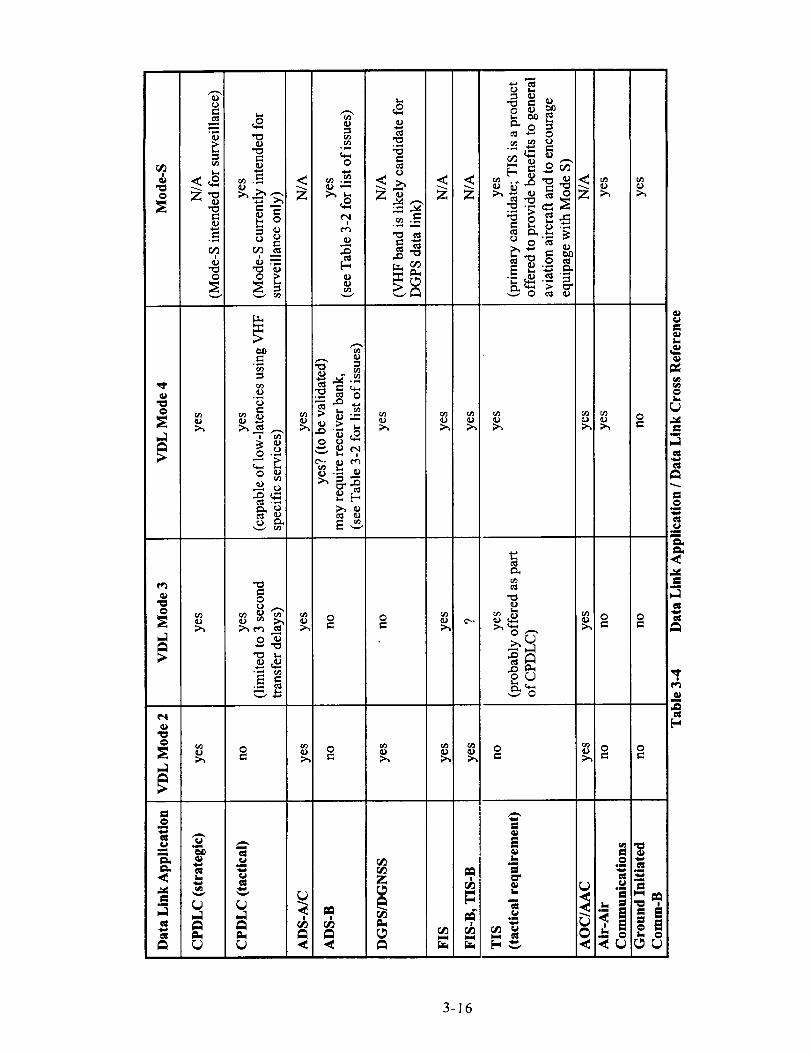
3-16
3.3 Overview of Planned CNS/A TM Data Link Applications
This section examines each of the planned CNS/ATM data link applications (shown in Table 3-
1) in terms of their communications requirements as they pertain to their possible allocation to
VDL. Among the top-level communications requirements for each application are coverage,
throughput, latency or transfer delay, addressed versus broadcast, availability, and integrity.
Required Communications Performance (RCP) for the various data link applications are
currently being developed in SARPS developments by the ICAO ATNP. RTCA SC-169 has
published draft MASPS for RCP for Safety Services [1].
3.3.1 CPDLC
Controller Pilot Data Link Communications (CPDLC) provides for routine air traffic
management communications via data link that are currently conducted via voicecommunications. These communications include air traffic control and traffic flow
management. RTCA DO-219 defines a message set and provides Minimum Operational
Performance Standards for a number of routine ATC messages.
The DO-219 message set was originally defined primarily to handle ATC communications that occur
during enroute operations. These messages are strategic in nature and can be received within relatively
modest transfer delays (- 1 to 10 sec are appropriate) via the ATN. CPDLC communications are of
high priority for flight safety and thus require high availability and integrity services from the ATN.
At present inconsistencies exist in the various definitions of the CPDLC message set (i.e.,
FANS-1 versus CNS/ATM-1) and the character-oriented and bit-oriented protocols (ARINC 622
and 623 data link layers). Hopefully, these inconsistencies will merge into a cohesive definition
of end-state CPDLC communications, otherwise ground and/or airborne data links will need to
be able to converse in multiple dialects of CPDLC, which is highly undesirable due to cost.
Candidate data links for CPDLC are VDL for enroute operations where a VHF ground network
is available, and SATCOM and HF data link in oceanic and remote enroute operations.
As aircraft approach terminal areas and particularly for surface operations, CPDLC communications
become tactical in nature (i.e., taxi instructions, hold short ofnmway, etc.,). In addition, the currently
defined message set must be upgraded to include surface and terminal area communications.
The current VDL Mode 1, 2 and 3 transition approach is focused primarily on providing strategic
CPDLC communications and is not addressing tactical CPDLC communications at this time.
Worst case VDL Mode 3 latency is expected to be - 3 see (95%). Potential candidates for
providing these tactical CPDLC messages are the VHF specific services (VSS) of VDL Mode 4
and the Mode-S specific service (MSSS).
CPDLC for TAP Data Link
As indicated above, the focus of CPDLC definition activity has been primarily on enroute
operations, with limited focus on terminal area operations. For the LVLASO flight tests, a number
of data link messages were created for surface operations CPDLC data link to supplement those
already defined in DO-219. VHF data link is expected to provide CPDLC data link in controlled
air space. However, for terminal area CPDLC, particularly surface operations CPDLC, low-
latency communications will be required. Whether current VDL Mode 3 can provide the neededlatency requirements are TBD. As indicated above, VSS of VDL Mode 4 or MSSS of Mode-S can
provide the low-latency, tactical communications needed for terminal area CPDLC.
3-17

In terms of message loading, individual aircraft require only minimal capacity (i.e., on the order
of~ 10 bps), thus 31.5 kbps and 19.2 kbps should provide sufficient data link capacity per
frequency channel.
While not categorized specifically as CPDLC, data link support for automation functions, such
as CTAS/FMS, could also be considered to fall into the category ofCPDLC. GICB using Mode-
S is a likely candidate to provide the needed, low-latency aircraft information that supports the
ground automation functions.
3.3.2 ADS-A (ADS-C)
Two forms of Automatic Dependent Surveillance (ADS) data link are being developed; 1)
addressed (also referred to as contract), ADS-A / ADS-C, and 2) broadcast ADS-B. These are
significantly different applications. ADS-A is described in this section. RTCA DO-212 MOPS
and ARINC Characteristic 745 have been developed to define ADS-A data link. ADS-B is
discussed in the next Section (3.3.3).
As indicated ADS-A are addressed, air-ground communications that provide information from
the aircraft to ground stations for air traffic control and management (ATC/ATM) and air traffic
services (ATS) purposes. ADS-A data link is primarily intended for oceanic and remote enroute
operations, allowing ATC to more closely monitor flight progress, aircraft state, meteorological
conditions, etc.. One of the key benefits of ADS-A is the ability for closer spacings between
aircraft in oceanic and remote areas compared to the large range buffers currently used for
spacing. This allows selection of preferred routes and supports higher traffic densities.
ADS-A communications are ground initiated (except for emergencies). Ground stations arrangecommunications with individual aircraft on a contract basis using three distinct contract modes: 1)
periodic, 2) event, and 3) demand driven. Typical communications are established using periodic ADS
reports as prearranged between the ground and the aircraft. ADS reports can also be transmitted by the
aircraft as a result of the occurrence of a particular event (e.g., vertical rate event, waypoint change
event, etc.), allowing ATC to track and monitor any significant changes that may impact ATC/ATM.
In addition, the ground station can request specific ADS reports from the aircraft via the demand
contract mode. ADS reports are strategic in nature and are expected to be sent via the ATN using -5
minute reporting rates (-1 minute rates in case of emergencies). ADS-A requires high availability and
integrity to enable closer separation for oceanic and remote area enroute operations.
The Basic ADS Group report contains aircraft position (latitude, longitude, altitude), time stamp
information indicating when the information is in effect, and a Figure of Merit (FOM) which
indicates the quality of the aircraft navigation source. A:ouong the numerous other ADS report
groups that have been defined are the Flight Identification Group, Predicted Route Group, EarthReference and Air Reference Groups, Meteorological Group, Intermediate Projected Intent and
Fixed Projected Intent groups, etc., and event groups indicating Lateral Deviation Change,
Vertical Rate Change, Altitude Range, and Waypoint Change events.
ADS-A is primarily intended for oceanic and remote enr)ute regions and utilizes the ATN forinter-network communications via SATCOM and HF data link. Note: ADS-A could also be
used in controlled enroute regions using VDL, although _he intent is primarily for use in oceanic
and remote areas. VDL Modes 2 through 4 will ultimately all be ATN compatible and can thus
provide the ADS-A service (Mode 1 is expected to be replaced with the higher data rates of
Modes 2, 3 and 4 and is not considered a long-term candtdate for ADS-A.
ADS-A / C for TAP Data Link
ADS-A / C is not intended for terminal area operations.
3-18
3.3.3 ADS-B
Unlike ADS-A(ddressed), Automatic Dependent Surveillance - broadcast (ADS-B) consists of
data link reports from aircraft that are broadcast to all interested ground and airborne users. In
addition, ADS-B provides tactical, low-latency communication within Radio Line of Sight
(RLOS) by using mode specific communications, i.e., non-ATN, which enables a wide range of
time-critical surveillance end user applications using the ADS-B messages set.
RTCA SC-186 recently completed the development of the ADS-B MASPS (version 6.0), which
defines the ADS-B message set in terms of information content and accuracy, specifies ADS-B
report update rates and reception success rates, service availability, and report integrity. Some of
the major surveillance-based applications envisioned to be supported by ADS-B are CockpitDisplay of Traffic Information (CDTI), Airborne Collision Avoidance System (ACAS), conflict
management, ATS surveillance, ATS conformance monitoring, and a runway occupancy and
incursion alert function. These applications impose a range of ADS-B data link requirements to
insure integrity and availability of function.
In addition to the wide range of ADS-B end user applications, a wide range of ADS-B capability
and equipage is envisioned for the various aircraft/vehicle types depending on the level of
capability desired. Low-end general aviation aircraft will likely require a minimal set of ADS-B
capability / equipage, sufficient to achieve desired benefits, while at the same time being
compatible with the overall ADS-B surveillance in the air space system. High-end air transport
aircraft will have increased ADS-B capabilities in support of more complex applications that
provide added benefits, e.g., air-air separation assurance in support of free flight.
The following tables from the ADS-B MASPS serve as a summary of the ADS-B message set
and state data link and operational requirements for several intended ADS-B end-user
applications. Table 3-5 provides a top level summary of the ADS-B message set as a function of
ADS-B applications. Most of the information elements are self-explanatory (NUC represents the
navigation uncertainty category, which indicates the quality of the aircraft's navigation system;
TCP refers to trajectory change point, providing aircraft intent information on planned changes
in the flight trajectory).
Table 3-6 identifies ADS-B performance requirements for a number of air-to-air ADS-B
applications, e.g., conflict avoidance, separation assurance, simultaneous approaches and airport
surface operations. The majority of these applications require high update rates on the order of 1
per second (update success rates). This is particularly the case for simultaneous approaches and
surface operations. Table 3-6 indicates expected acquisition ranges, aircraft / vehicle densities,
alert times, NUC and availability and integrity of ADS-B reports.
Table 3-7 provides a summary for ADS-B performance requirements in support of ground-based
ATS surveillance and conflict management as a function of flight phase. ADS-B report update
rates for enroute, terminal area, and surface operations are 12 seconds, 5 seconds, and 1 second,
respectively, with parallel runway approaches also requiring 1 second updates. Operational
ranges for ATS surveillance can be as large as 200 nmi.
While Tables 3-6 and 3-7 represent air-to-air and ground-to-air surveillance applications,
respectively, it is expected that air-to-air ADS-B applications will be the first to becomeoperational since they do not require deployment of ground infrastructure. Regardless of air or
ground-based surveillance applications, it is evident that ADS-B requires a tactical data link.
3-19

InformationElement
Aid to ConflictVisual Avoid-Acqwi- a:_tion
Szpmst- FliBht Path Simulta-ion As- Deconfliction neous Ap-
& Planning
S_ce
(AfV mA/V&A/Via
ATS)
ATSSurveillance
Identification
CallSi_'Address
Cate_or_
State VectorHorizontalPositionVer_cal PositionHorizontal
VelocityVe_calVeloci_TurnRate
.... 7"7"_. _'._
n/r rotR R
n/r n/r
R R
RR
R
R
RRR
i
R
RR
RR
n/r
R
I I
RRR
i
R
RR
RRn/r
RRR
R
RR
RRn/r
R
.- _'_._..L,
R
R
Ri
R
n/r
R
n/rn/r
R
I
_'_Z.;_,'_-:,-_ .,_-_k)_
RRR
R
RR
R
R
Rn/r n_t
Speed Change n/r n/rRateNUC, .NUCt R R
Status andIntent
R R
n/rn/r
R
I
IJ I I I I I
............. _.- ---_-.--_.,--_.:_.__-;',_--_:_........ ........ _ ....
Emergency/Priori n/r n/r n/r n/r n/r n/r RStat_s
TCP" n/r n/r R R .n/r n/r n/rTCP+ I_ n/r n/r n/r R n/r n/r n/r
R = Required
n/r = not required to support the indicated ADS-B application. The item, if provided,
may be used to improve the performance of the application.
Table 3-5 Summary of Information Needs for Applications Supported by ADS-B(from ADS, B MASPS)
3.3..3.1 ADS-B Data Link Considerations
The ADS-B MASPS defines performance requirements independent of any specific datalink
media. Thus any data link system that satisfies the most stringent ADS-B requirements in terms
of message size and corresponding update rate, availability, integrity and coverage is a potential
candidate for ADS-B data link. Several data link approaches are being considered in industry to
provide the ADS-B data link application, the two most prominent being Mode-S and VDL Mode
4 data link. Studies have been conducted that have assessed the capacity (and in the case of
Mode-S the interference effects of ADS-B on existing IC30/I090 MHz transmissions) of
providing ADS-B data link in high density traffic using the Los Angeles Basin as the worst case
traffic load (in excess of 1250 aircraft for a distribution c f airborne and surface traffic) [2] [3] [4].
3-20
These studies suggest that either of these data links can provide the necessary ADS-B data link
capacity. Mode-S uses random access protocols on the 1090 MHz frequency for broadcast of
ADS-B reports. VDL Mode 4 uses TDMA channel access protocols using several dedicated
VHF frequencies for ADS-B for the enroute global signaling channels, terminal area, precision
approach monitor and surface operations. While multiple VHF frequencies would be requiredfor ADS-B in the LA Basin area, only a subset of these will be required at any given time for
reception in the aircraft. Discussion of the numerous, and somewhat complex issues pertainingto Mode-S versus VDL Mode 4 for ADS-B data link is deferred to Section 4.3.6 and 4.3.7 in
Appendix D. Implications of the selection of either data link on the future CNS/ATM data linkarchitecture are addressed in Section 3.5.
3.3.3.2 ADS-B and ACAS (Airborne Collision Avoidance System)
This section examines the relationship between ADS-B and ACAS and its potential impact on
the selection of the ADS-B data link. As indicated above ADS-B is envisioned to support
numerous applications that require surveillance information. These can be categorized as 1)
separation assurance, 2) collision avoidance, and 3) situational awareness. Separation assurance
applications receive ADS-B surveillance information and perform conflict detection processing
to determine when loss of separation may occur. Before this occurs, aircraft can negotiate route
changes that continue to assure separation.
Collision avoidance is intended as a last resort safety function, when the separation assurance
function has failed. Thus, collision avoidance and separation assurance must be independent
functions. Situational awareness provides supplemental information to the flight crew and does
not impose any independence requirements.
Both collision avoidance and separation assurance functions can benefit from data provided by
ADS-B. The current TCAS (also referred to as ACAS II) can greatly benefit from the additional
state vector and intent ADS-B reports in reducing nuisance alarms, particularly when aircraft are
closely spaced as in simultaneous parallel runway approaches. At the same time, ADS-B can be
used to support the separation assurance function associated with closely-spaced parallel
approaches. However, the independence required between separation assurance and collisionavoidance function necessitates that the information used by these systems is also derived
independently (i.e., measured independently not just transmitted independently). TCAS can
accomplish this independence by using active interrogations to confirm the accuracy of the ADS-
B report. It is likely that any new ADS-B and ACAS system must provide this mechanism for
independence.
Another requirement for collision avoidance is that two or more aircraft which have lost
separation coordinate their intended evasive maneuvers. This requires a cross-link between the
aircraft. TCAS accomplishes this using the Mode-S link.
Any new ACAS using ADS-B via a new data link faces the following obstacles:
1) independence of ADS-B data must be assured with the separation assurance function (use of
active interrogations is the likely means), 2) requirement for a cross-link for coordination of
resolution advisories, and 3) compatibility with the current TCAS II which is Mode-S based.
The latter point requires that fielded TCAS equipment be made compatible with any new ADS-B
and ACAS function, or more likely, that a new ACAS be fully compatible with the existingTCAS.
3-21

c>,=
_ _a 0
_ .m -, [-'
_- _ _-_ _. - o _ _,
bm _
<:_-_
_-/: =N, _o-= _ _,
• "-- 00"_ i::_."-
" rd_
t',,I
0
<:
°_
o
@
It
Es_
¢',,I _
0
v e_
0 V
s_
_<
<i
!
<
o
L.
S
[-
3-22

II
Information
Initial Acqubn'tionof A/V Call Signmd AN Cmlpry
Pmition ErrorReceived
UpdateUpd_ SuccessRate
Oper_Domain Radius
(nn_)Ope_ Trte_Densities"
ServiceAvailability' {%)
En Rmae
wfm24 sec.
350 ,_ [7]
12 see. [14]
98%
2OO
12.50
99.999 [14]99.9 0ow _)
w' [141
o e.J'c.e.mnTermed A_,m S,a_:e
w/inI0 sec.
150 m. [7]
5 sec. M
98%
6O
750 [7]
99.999 D4]99.9 .,t)
!o"[14]
i
w/in10 sec.
3 m. rm_ 9 m.bias I241J'rk [151
lser.
i
98%M
5
IOOin motion;150 fixed
i
99.999D4]
io"[14!
pmneIRmw_Co_m'm M_.
n/a
9m.
1 IJec.
98%
10
'50dual; ,75 u'i#e;
w/o filter: 15099.9
i
re"[141
a) Ref_ areprm,Med whereapplicable.EI_ bes_j_onem was _ toobca_JI_/ormon_dm_
b) Receivedupdazepev_ isO_eper_ benveenreceiveds'tatevector_dates.MF CallSign and A/V Category can be received at a lowev ma_.
c) One or mulriple ground recefve_ may be uaed in the operatzbnal domain to entreacceptable performance for the intemted _ loa&
d) Serv_ availability indud_ any other O,stms providms add_nal _ of.am'_illance infomuufo_
e) dltiaule accuracy: additional ben_t$ can be gained by using 25ft., or better./) Integrity mlues are defu_ _ the probabill_ o/ two succms_ r_ts bav_
umdaec_ a_damt m'ors.
Table 3-7 Summary of ADS-B Requirements for ATS Provider Surveillance and
Conflict Management Applications (as a function of Flight Phase)
(from ADS-B MASPS)
Use of a data link that supports future ADS-B and ACAS that is incompatible with Mode-S must
deal with the legacy of TCAS using the Mode-S link. For example, assuming that ADS-B is
provided via a VHF data link such as VDL Mode 4, separation assurance applications can be
developed based on this capability. ACAS on the other hand will consist of TCAS equipment, atleast in the short term, and continues to require transponder equipage for all aircraft. Thus,
during initial deployment of VHF ADS-B, aircraft will require dual equipage with VHF ADS-Band Mode-S transponders. Not until a VHI: based ACAS is developed, which is capable of
active interrogations (for independence with separation assurance functions) and provides across-link between aircraft for coordination, can the air space system transition to a fully
ADS-B and ACAS system, eliminating the need for Mode-S transponders. During the interim, a
difficult and carefully orchestrated transition away from TCAS to ACAS would be required.
Thus while the previous section indicates that from a technical perspective, ADS-B can be
provided by either Mode-S or VDL Mode 4 data links, the selection of the appropriate data link
is _eatly influenced by the relationship of ADS-B to TCAS / ACAS.
3-23

3.3.3.3 Ground Interrogation of Aircraft Mode-S Registers
In the evolution of the development of Mode-S, 255 regi sters have been allocated within the
Mode-S transponder (also referred to as the Mode-S registers) for storage of a wide range of
useful aircraft information. A number of these registers have been set aside to contain the
extended squitters that represent the ADS-B message set. While the intent of ADS-B is to
broadcast these extended squitters periodically (per the requirements defined by the ADS-B
MASPS) for use by all other users to provide the ADS-B surveillance applications, an alternate or
supplementary approach being considered is to use ground station interrogators for control of thisinformation. Using this ground-based approach, ground-initiated interrogations using the Mode-S
Specific Protocol (MSP) defined by the ICAO Mode-S Specific Services can request read-outs of
specific registers via transponder replies (also referred to as Ground Initiated Comm-B {GICB}).
Thus, there are two distinct philosophies to surveillance, 1) air traffic control using strictly ground-
based control / surveillance, with the ground being fully responsible for all control, and 2) a shared
responsibility for air traffic management using ADS-B between ground and airborne users, with
reliance on air-to-air separation assurance, while ground stations provide conformance monitoring
of flight progress, and intervene in case of loss of separation. The second approach, where ADS-B
is at parity with the ground surveillance system in sharing responsibility for separation assurance is
the preferred approach by air space users, since it is compatible with the goals of free flight.
A mix of ADS-B and some GICB data link messaging can also be used to provide pertinent
information, such as weather reports by aircraft, and to provide 4-D surveillance for better time-
of-arrival estimation and sequencing by the CTAS (Center TRACON Automation System) to
improve terminal area operations.
ADS-B for TAP Data Link
ADS-B plays a vital role in Terminal Area Productivity (TAP) data link. ADS-B supports
surveillance of aircraft operations in the terminal area aii space, during landing and approach
(including parallel runway approaches) and for surface operations. This is particularly important
during low-visibility weather conditions, when controllers and pilots can no longer rely on visual
contact in conducting operations. For efficient, safe temlinal area operations in low-visibility
conditions, high integrity surveillance using ADS-B is a requirement.
Mode-S and VDL Mode 4 data link are the primary cand idates for ADS-B. The FAA and RTCAhave selected Mode-S as the near-term data link for AD_-B. Both Mode-S and VDL Mode 4 are
expected to provide the necessary data link capacity for t_-m'ninalarea ADS-B for worst case traffic
densities (i.e., LA Basin) [2][3][4]. The 1030 / 1090 M_3z Mode-S link is expected to provide the
required communications performance for terminal area M)S-B (5 sec update rates in terminal
area and 1 sec update rates for parallel runway approaches and surface operations). Four VHF
channels are anticipated to be needed for VDL Mode 4 to provide the necessary capacity and
performance for terminal area ADS-B (refer to Section 4 X.X in Volume II of report).
3.3.4 DGPS/DGNSS (LAAS)
The ICAO Global Navigation Satellite System Panel (GNSSP) and RTCA SC-159 are currently
developing SARPS and MASPS requirements for the Lo:al Area Augmentation System (LAAS) in
support of precision approaches (Cat I, II and III). This activity includes the definition of the
message set and data link for uplink of GPS/GNSS corre:tions and integrity information to airborne
GPS receivers. The DGPS/DGNSS data link application is a broadcast ground-to-air service and is
flight critical, requiring very high integrity, availability, .rod continuity of service. The data link
3-24
requireslowtransferdelays,i.e.,isnon-ATN,onlyusingthephysicallayerandTDMA MAC layer
services. Expected data link coverage range is a 20 to 30 nmi radius from the airport.
The data link defined in RTCA DO-217, Appendix F is the leading candidate for LAAS, using
31.5 kbps D8PSK modulation and TDMA channel access using 0.5 second frames, each
consisting of eight 62.5 ms time slots. This data link approach is being upgraded to meet LAAS
requirements. The DO-217 VHF data link physical layer modulation waveform is very similar to
the VDL Mode 2. Another candidate approach being considered is 19.2 kbps GFSK modulation,
using either the same TDMA slot structure as indicated above or a derivative of VDL Mode 4TDMA time slots. Data link selection considerations are frequency reuse (based on D/U co-
channel interference of the modulation waveform), data link capacity, and compatibility with
other VDL modes (compatibility with VDL Modes 2 and 3 or with VDL Mode 4).
DGPS / DGNSS for TAP Data Link
DGPS / DGNSS data link will be required for TAP data link for precision approach services and
for low-visibility surface operations when used for navigation guidance. VI-IF data link is the
expected broadcast data link for DGPS / DGNSS using 31.5 kbps D8PSK or possibly 19.2 kbps
GFSK signals-in-space.
3.3.5 FIS, FIS-B
The future CNS/ATM system is expected to provide a number of flight information services
(FIS) that provide for increased flight safety. Some FIS data link services are already in use
(e.g., Predeparture Clearance, D-ATIS). FIS data link uses both addressed and broadcast
communications depending on the application. The following list of FIS applications are either
currently in use or are in the planning stages:
- Predeparture clearance
- Digital Automatic Terminal Information Services (D-ATIS) consisting of latest weather
observations and specific airport data
- Windshear advisory service
- Pilot reports (PIREP) service
- Notice to Airman (NOTAM) service
- Runway Visual Range service
Precipitation mapTerminal Weather Service
1) Terminal Weather Information to Pilots (TWIP) consisting of information from Terminal
Doppler Weather Radar (TDWR) or Integrated Terminal Weather Service (ITWS)
2) Graphical Weather Service (GWS) consisting of precipitation maps and a graphicversion of TWIP
3) Textual weather products.
Some of the above services have been implemented via request-reply ACARS data link (VDL Mode
1), while GWS of precipitation maps and TWIP using image compression and subsequent transmission
via Mode-S extended length messages (ELMs) are also being developed. The motivation for these FIS
products are to utilize the existing ACARS link to provide services and also to use Mode-S to provide
benefits for general aviation aircraft that encourage them to equip with Mode-S transponders. In the
long term, the ACARS FIS data link applications are expected to transition to the higher data rate VDL
modes (VDL Modes 2 and 3 or VDL Mode 4) using ATN-compatible sub-networks.
3-25

In additionto theseaddressedFISservices,theuseof broadcastservices(FIS-B)of graphicalweatherinformationcanbeachievedbyutilizingVDL in abroadcastmode,e.g.,usingVDLMode2(CSMA)inasimplexbroadcastmode.VDL Modes3and4 couldalsoprovideFIS-Bservices.
FIS, FIS-B for TAP Data Link
The above FIS and FIS-B services are expected to be provided for both enroute and terminal area
operations using VDL Modes 2, 3 or 4.
3.3.6 TIS, TIS-B
Traffic Information Service (TIS) is intended to increase pilot situational awareness by providing
information of proximate traffic to the attention of the pilot and is particularly beneficial to
general aviation pilots. By providing the TIS service, it is hoped that general aviation pilots see
sufficient benefits to equip with Mode-S transponders, wtdch at the same time facilitates thetransition to ADS-B surveillance. The TIS service is provided by ground stations using Mode-S
sensors that are equipped with the TIS software package, which processes surveillance replies to
detect close proximity traffic to TIS equipped aircraft and uplinks this information to that aircraft
as part of a long Mode-S interrogation. In this manner, ]'IS equipped aircraft are informed of
transponder equipped aircraft even if the other aircraft is not TIS equipped. The TIS equippedaircraft initiates the TIS service by including a TIS request to the ground sensor.
TIS is intended to display traffic within 5 nmi and +/-1200 ft altitude of the requesting aircraft.
Clearly TIS is a tactical data link application and is implemented using mode specific data link
services (i.e., non-ATN).
TIS-B (TIS-broadeast) is a potential data link application for future broadcast services of traffic.
This is particularly important on the airport surface in low-visibility weather conditions, where
the ground surveillance system informs all surface aircrat: and vehicles of the other traffic. Due
to the potential for a large amount of surface traffic, a broadcast data link is more efficient than
using addressed TIS data link. On the airport service, a b-oadcast VHF data link (Modes 2, 3, or4) similar to the FIS-B data link for weather services coulzl be used to provide this service.
TIS, TIS-B for TAP Data Link
TIS is intended to be a service primarily for low-end general aviation aircraft to aid "see and avoid"
traffic operations and to alert pilots of proximate aircraft. TIS-B is expected to play a significant role
in terminal area operations for situational awareness for both controllers and pilots (Cockpit Display
of Traffic Information). TIS-B was demonstrated in the I.VLASO flight tests and demonstration and
is expected to be a requirement for low-visibility surface 3perations, providing both controllers and
pilots with a consistent view of the traffic environment. A single VHF channel is expected to
provide sufficient throughput to support broadcast uplink of traffic information for greater than 200
aircraft per second (Section 2.4.3.2). At this time, the TIS-B data link concept / application has not
been developed by industry committees. The LVLASO flight test employed an experimental TIS-B
data link to provide traffic information for display in the NASA 757 flight deck.
3.3.7 AOC/AAC
Airline Operational Communications (AOC) and Airline _dministmtive Communications
(AAC) are currently sent via ACARS VDL Mode I addressed data link. In the future CNS/ATM
system, these communications can be sent via VDL Modes 2, 3 or 4 or SATCOM and I-IF datalink in remote areas. These communications are strategic in nature and will be sent via the ATN
between aircraft, the service provider, and the airline.
3-26

AOC/AAC for TAP Data Link
No additional role for AOC/AAC is envisioned. These communications will continue to evolve
in time and are expected to transition to the higher-rate VDL modes (Modes 2, 3, or 4) for higher
update rates and capacity.
3.3.8 Air-Air Communications
Currently the only air-air data link application in use are TCAS air-to-air coordination
interrogations and replies via the Mode-S link between aircraft selecting appropriate resolutionadvisories to resolve threatening encounters. In the future the use of Airborne Collision
Avoidance System (ACAS) cross-link is expected to provide improved surveillance for
separation assurance and collision avoidance, by providing an independent cross check on ADS-
B surveillance reports and also providing high update rate, low latency information exchanges
between aircraft. In the near term the Mode-S link is expected to serve as the ACAS cross-link
data link. Another future air-to-air data link application is for route or trajectory negotiations
between aircraft conducting free flight operations.
Air-to-air addressed data link applications are tactical in nature and require use of non-ATN
mode specific service. Mode-S and VDL Mode 4 are candidate data links using MSSS and VSS,
respectively
Air-to-Air Communications for TAP Data Link
Air-to-air communications are expected to provide significant benefits for surveillance during
parallel runway approaches to closely-spaced runways in low-visibility conditions. The exact
role of active air-air crosslink between aircraft on parallel approach and passive ADS-B
surveillance is yet to be determined. However, air-air crosslink will likely be required to assure
independence between separation assurance and collision avoidance functions and to provide
coordination between aircraft as a threatening situation develops.
It is apparent that most of the CNS/ATM data link applications indicated above also play a
significant role for Terminal Area Productivity (TAP) data link. Thus the data link allocations
discussed next (Section 3.4) and the candidate data link architectures (section 3.5) directly applyto TAP data link.
3-27
3.4. Allocation of CNS/A TM Data Link Applications to Data Links
This section examines possible allocations of CNS/ATM data link applications to respective data
link candidates. From these allocations it then becomes possible to postulate data link
architectures. Tables 3-8 to 3-10 list the anticipated CNS/ATM data link applications and
indicate which of the data links (VDL Modes 1 to 4, Mode-S, SATCOM and I-IF) are likely
candidates in providing the service. Table 3-8 identifies data link allocations for terminal area
and airport surface operations, Table 3-9 addresses cnroute (non-remote area, i.e., with ATC
ground networks in place) operations, and Table 3-109 is for oceanic and remote enroute
operations. From Tables 3-8 to 3-10, it is evident that a wide range of data link mappings are
possible.
In order to compress the available options, data link applications are reduced into four distinct
groups, since it is expected that services within any one of these groups would be assigned to the
same data link. The four data link groups identified are as follows:
1) Air traffic control (ATC) group consisting of CPDLC and ADS-A
2) ADS-B group (ADS-B but may also include TIS and air-air data link)
3) Air traffic services (ATS) group consisting ofFIS, FIS-B, and TIS-B
4) AOC/AAC group for airline communications
Note that DGPS/DGNSS data link has been removed from the list of data link applications since
it is expected that it will be implemented as a separate module within a Multi-Mode Receiver
(MMR) for precision approaches, or within the GPS sensor itself. It is desirable for cost
purposes that the physical layer modulation of the VHF DGPS/DGNSS data link is the same as
that used by VDL, however this is not a requirement. DGPS/DGNSS data link will likely use
either 31.5 kbps DSPSK or 19.2 kbps GFSK modulation and will use its own specific TDMA
frames and time slot structure (i.e., similar but not the same as VDL).
TIS and air-to-air data link (for trajectory negotiation anct/or ACAS cross-link) are grouped with
the ADS-B group. These applications primarily use specific services (i.e., non-ATN) that could
be accomplished via MSSS using Mode-S or VSS on VEL Mode 4. TIS is primarily a service
intended for low-end general aviation users.
In addition, SATCOM and I-IF data links will not be con.,idered in further allocation mappings
since they are used primarily during distinct operational phases (i.e., oceanic and remote enroute)
and can easily be separated from the other more complex data link allocations. Table 3-11
shows a compressed mapping of data link services based on the allocations of Tables 3-8 to 3-10.
Since VDL Mode 4 is relatively new compared to the mere established VDL Modes 2 and 3 and
Mode-S, Table 3-11 is organized as follows. Option #1 c!escribes a data link allocation that does
not utilize any VDL Mode 4 capability (i.e., ATC, ATS _nd AOC/AAC group data links are all
allocated to VDL Mode 2 and / or VDL Mode 3 and ADt;-B is via Mode-S). Subsequent
allocation options that may be feasible allocate an increa_ing number and various combinations
of data link applications to VDL Mode 4. A total of eight allocation options were identified,
with Option #8 consisting of an all VDL Mode 4 data lint system.
3-28

3-29

3-30

3-31

Data Link Application
Option #1
ATC group
(CPDLC, ADS-A)
ATS group
(FIS, FIS-B, TIS-B)
Allocated Data LinkComments
(From perspective of
VDL Mode 4 allocation)
AOC/AAC group
(airline group)
ADS-B group
Option #2
ATC group
(CPDLC, ADS-A)
ATS group(FIS, FIS-B, TIS-B)
AOC/AAC group
(airlme group)
ADS-B group
Option #3
ATC group
(CPDLC, ADS-A)
ATS group
(FIS, FIS-B, TIS-B)
AOC/AAC group
(airline group)
ADS-B group
Option #4
ATC group
(CPDLC, ADS-A)
ATS group
(FIS, FIS-B, TIS-B)
AOC/AAC group
(airline group)
ADS-B group
VDL Mode 2 and / or VDL Mode 3
Mode-S
VDL Mode 2 and / or VDL Mode 3
VDL Mode 4
Mode-S
VDL Mode 2 and / or VDL Mode 3
VDL Mode 4
Mode-S
VDL Mode 4
Mode-S
No applications usingVDL Mode 4 in this scenario
AOC/AAC groupvia VDL Mode 4
AOC/AAC and ATS groupsvia VDL Mode 4
All groups use VDL Mode 4
except ADS-B group
Table 3-11 Data Link Allocations Per Application Groups
3-32

Data Link Application
Option #5
ATC group
(CPDLC, ADS-A)
ATS group
(FIS, FIS-B, TIS-B)
AOC/AAC group
(airline group)
ADS-B group
Option #6
ATC group
(CPDLC, ADS-A)
ATS group
(FIS, FIS-B, TIS-B)
AOC/AAC group
(airline group)
ADS-B group
Option #7
ATC group
(CPDLC, ADS-A)
ATS group(FIS, FIS-B, TIS-B)
AOC/AAC group
(airline group)
ADS-B group
Option #8
ATC group
(CPDLC, ADS-A)
ATS group
(FIS, FIS-B, TIS-B)
AOC/AAC group
(airline group)
ADS-B group
Allocated Data Link
VDL Mode 2 and / or VDL Mode 3
VDL Mode 4
VDL Mode 2 and / or VDL Mode 3
VDL Mode 4
VDL Mode 2 and / or VDL Mode 3
Comments
(From perspective of
VDL Mode 4 allocation)
ADS-B groupvia VDL Mode 4
AOC/AAC and ADS-B groupsvia VDL Mode 4
All service except ATC groupvia VDL Mode-4
All groups use VDL Mode 4in this scenario
VDL Mode 4
VDL Mode 4
Table 3-11 Data Link Allocations Per Application Groups (continued)
3-33

Therationalefortheseallocation options using incrementally more VDL Mode 4 use are as follows:
Option #1: No VDL Mode 4; MOde-S ADS-B with all other data link via VDL Modes 2/3.These data links meet the application requirements and VDL Mode 4 adds noadditional benefits.
Option #2: AOC/AAC to VDL Mode 4, i.e., a new service provider network for airlinecommunications via VDL Mode 4.
Option #3: AOC/AAC and ATS (FIS, FIS-B, TIS-B) to VDL Mode 4, i.e., all service provider
and flight services data link via VDL Mode 4.
Option #4: All data link via VDL Mode 4, except for Mode-S ADS-B.
option #5: Only ADS-B via VDL Mode 4, all other data link via VDL Modes 2/3.
option #6: All ATC/ATS services via VDL Modes 2/3 using integrated digital voice and data
capability; ADS-B and airline communications via VDL Mode 4.
Option #7: Controller data link (i.e., ATC group) via VDL Modes 2/3 using efficient, integrateddigital voice and data capability; all other data link and ADS-B via VDL Mode 4.
Option #8: All data link via VDL Mode 4.
The next section develops CNS/ATM data link architecU:re candidates based on these eight data
link allocation options.
3-34

3.5. Candidate Avionics Data Link Architectures for CNSIATM and TAP
The candidate data link architectures below are developed for CNS/ATM capable air transport
aircraft and will thus consider worst case data link requirements in terms of 1) number of
services, 2) required communications performance (RCP), and 3) high-density traffic loadings
(e.g., LA Basin being worst case loading). These candidate data link avionics architectures
therefore reflect a typical avionics data link suite required for air transport aircraft.
The following data links are assumed to be included in all of the future CNS/ATM data linkarchitectures discussed below:
1) WAAS data link (data link accomplished via GPS signal and thus included in GPS sensor).
Dual WAAS GPS receivers are expected to be required.
2) LAAS (DGPS/GNSS) data link is expected to be a VI-IF data link using either 31.5 kbps
D8PSK or 19.2 kbps GFSK. The LAAS data link is expected to be integrated in a Multi-
mode Receiver (MMR) or the GPS sensor and is not considered within the VDL modes
discussed below. Dual or triple redundant MMR or GPS sensors are expected to be required.
3) Dual SATCOM and dual I-IF data link are required for oceanic and remote-area enroute datalink.
3.5.1 VHF Radio Resource Requirements versus Data Link Allocation Options
The data link allocations from Table 3-11 are examined more closely to determine the radio
resource requirements. A number of observations are in order:
1) Conventional analog AM voice capability must be included since not all parts of the world
will have digital voice capability for a very long time.
2) ADS-B end user applications that provide Airborne Separation Assurance System (ASAS),
Airborne Collision Avoidance System (ASAS), and Situational Awareness (SA) are expected
to be functionally integrated in TCAS, FMS etc., avionics equipment.
ADS-B data link candidates are Mode-S data link or VDL Mode 4. For Mode-S ADS-B,
dual Mode-S transponder are required (on/standby).
For low-latency, tactical CPDLC, only VDL Mode 3 and VDL Mode 4 are viable candidates.
VDL Mode 2 (CSMA protocol) is not adequate for low-latency CPDLC. To achieve 1 sec
latencies may require VHF Specific Services (VSS) in place of ATN-compatible services.
Mode-S Specific Service (MSSS) are also capable of low-latency CPDLC. However, FAA
and RTCA have stated that Mode-S shall only be used for surveillance.
VHF/VDL radio tuning/retuning can be accomplished manually by the pilot via aural or data
link instructions from ATC. Tuning/retuning can also be done automatically by FMS or data
link equipment. Radio tuning is accomplished via the physical and data link layers and
should be invisible to the virtual circuit connection of the network layer. There is a potential
for a "make-before-break" requirement, where the next station is contacted ("make") before
the current station is dropped ("break"). If"make-before-break" is a requirement, an
additional radio resource will be required, at least until the new connection is made. For this
analysis, "make-before-break" is assumed not to be a requirement.
Based on VDL Mode 4 capacity studies (refer to Appendix D, Section 4.3.6), for high-traffic
densities, two receive channels are required for enroute ADS-B using the two Global Signalling
Channels (GSCs), and two receive channels are required for terminal area ADS-B. During the
3)
4)
5)
6)
3-35
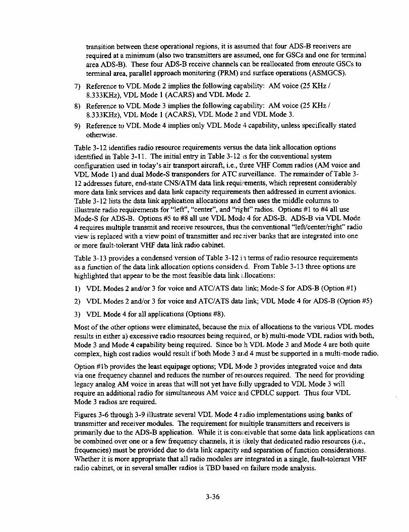
transition between these operational regions, it is assumed that four ADS-B receivers are
required at a minimum (also two transmitters are assumed, one for GSCs and one for terminal
area ADS-B). These four ADS-B receive channels can be reallocated from enroute GSCs to
terminal area, parallel approach monitoring (PRM) and surface operations (ASMGCS).
7) Reference to VDL Mode 2 implies the following capability: AM voice (25 KHz /
8.333KHz), VDL Mode 1 (ACARS) and VDL Mode 2.
8) Reference to VDL Mode 3 implies the following capability: AM voice (25 K/-Iz /
8.333KHz), VDL Mode 1 (ACARS), VDL Mode 2 and VDL Mode 3.
9) Reference to VDL Mode 4 implies only VDL Mode 4 capability, unless specifically statedotherwise.
Table 3-12 identifies radio resource requirements versus the data link allocation options
identified in Table 3-11. The initial entry in Table 3-12 is for the conventional system
configuration used in today's air transport aircraft, i.e., three VHF Comm radios (AM voice andVDL Mode 1) and dual Mode-S transponders for ATC surveillance. The remainder of Table 3-
12 addresses future, end-state CNS/ATM data link requirements, which represent considerably
more data link services and data link capacity requirements then addressed in current avionics.
Table 3-12 lists the data link application allocations and then uses the middle columns to
illustrate radio requirements for "left", "center", and "right" radios. Options #1 to #4 all use
Mode-S for ADS-B. Options #5 to #8 all use VDL Mode 4 for ADS-B. ADS-B via VDL Mode
4 requires multiple transmit and receive resources, thus the conventional "left/center/right" radio
view is replaced with a view point of transmitter and receiver banks that are integrated into oneor more fault-tolerant VI-IF data link radio cabinet.
Table 3-13 provides a condensed version of Table 3-12 i a terms of radio resource requirements
as a function of the data link allocation options consider(d. From Table 3-13 three options are
highlighted that appear to be the most feasible data link :.llocations:
1) VDL Modes 2 and/or 3 for voice and ATC/ATS dat_ link; Mode-S for ADS-B (Option #1)
2) VDL Modes 2 and/or 3 for voice and ATC/ATS da_ link; VDL Mode 4 for ADS-B (Option #5)
3) VDL Mode 4 for all applications (Options #8).
Most of the other options were eliminated, because the mix of allocations to the various VDL modes
results in either a) excessive radio resources being requiI ed, or b) multi-mode VDL radios with both,
Mode 3 and Mode 4 capability being required. Since boh VDL Mode 3 and Mode 4 are both quite
complex, high cost radios would result if both Mode 3 as_d 4 must be supported in a multi-mode radio.
Option #1b provides the least equipage options; VDL Mode 3 provides integrated voice and data
via one frequency channel and reduces the number of resources required. The need for providing
legacy analog AM voice in areas that will not yet have fitly upgraded to VDL Mode 3 will
require an additional radio for simultaneous AM voice aJld CPDLC support. Thus four VDL
Mode 3 radios are required.
Figures 3-6 through 3-9 illustrate several VDL Mode 4 radio implementations using banks of
transmitter and receiver modules. The requirement for nmltiple transmitters and receivers is
primarily due to the ADS-B application. While it is cont:eivable that some data link applications canbe combined over one or a few frequency channels, it is iikely that dedicated radio resources (i.e.,
frequencies) must be provided due to data link capacity and separation of function considerations.
Whether it is more appropriate that all radio modules are integrated in a single, fault-tolerant VHF
radio cabinet, or in several smaller radios is TBD based on failure mode analysis.
3-36

0
0
0
o
•- _
° _ _N o eL ¢) o
= _-_ _e <
-__ o• ¢._
o <<c_< N
._000
0
_,_,_ ,_
= _ _
"T
3-37

I::
o
"0
t.... _ N
•":= 0
QJ _
,._ _ E ._ .=
.._ -- .= ..= <
_._ _
_'_ _._ _ ,.,.._'_
0
::E
_o
0 _ _
<_ _0
_*-
=:o
Q.0=lo
omm
.<
I::.,==
e=
o
c_,,,_-....
o__o_<
"0o
.1 o
>._
o o o
z
_I 0 0 0
t=i ;> N
oO ..
o
* .<
o
,io
3-38

EEo
,.o_ <__ 0_ _'_
.=
_-=
" ___ _ _ _
m
°_oE
_o
o _
o
.u
o
o
0
mm
o_
_ 0 o o
"-- "L"
e_g
_-_ _ -r.
,_ "°
_ o
a8
o
o
o
0<
.£ ,-, _ .£
_-o _
._000
"-- "L"_,_ .,_
•-_ _ _ _J_
_ "--
;>_
o
.m
[..
3-39

3-40

Q;
o
m
o
Q;
o,m
0
o
om
.l,q
E--
o
o
_o
0
o
o o
o_
!
o
o 0 o
_NNN
o<<<
o
_ _ O_o
_:_.i ,_-_ _i __._ _ _
0 ,-., t_
°_ _
c_
.o
o
_.-=
o o
(J
(J©<
o
o
o._,,_
oum
*m
o
0
Q;
Q;
Q;
Q;
o
e_
3-41

-=;>
o _._. .._._
ep.
__
_ m
o
e_0
o
"_ "_ "_1o o o o
_ =_ _ i_=_ _"
.=
o
o*N
¢II
f,l
M
3-42
.__
o o
_, _ _ _-
•g _ ;-_
e_
.._ __ _ _
_'"_ 0 _ _,.
_ _ •
_ _.-.__'N'--
"" _' _ _,1
O
.__ o
,_ o
"_r_ _o6
"" N "_o<
__" 0 O_
' _ 0
o_ _._
_._ _ _
o°_
e_O
o°_
o
III
I_ 0 0 0 0 0 0 0
_ ,_
2_
o
o o
.-_
o o o
._ ,_ m
-- "2-_ _
O
.m
o
e_O
oom
o
_M
o
o
O
O
O
o
O
o
m
3-43

Allocation Option
Option #1a:
(no VDL Mode 4)
Option #1b:
(no VDL Mode 4)
Option #2a:
(AOC on Mode 4)
Option #2b:
(AOC on Mode 4)
Option #3a:(AOC/FIS on Mode 4)
Option #3b:
(AOC/FIS on Mode 4)
Option #4:
(AOC/FIS/CPDLC on
Mode 4)
Option #5a:
(ADS-B on Mode 4)
Option #5b:
(ADS'B on Mode 4)
Option #6a:
(ADS-B, AOC on
Mode 4)
Option #6b:
(ADS-B, AOC on
Mode 4)
Option #7a:
(ADS-B, AOC, FIS on
Mode 4)
Option #7b:
(ADS-B, AOC, FIS on
Mode 4)
Option #8:All on Mode 4
Table 3-13
Radio Resources Count
(single-mode VDL Mode 4 radios)
4_(5) VDLMode 2 radios, [NA2 M_Ie.S ttmlsponder
4 (3 + 1 AM void) VDL Mode 3 radios, NA2 Mode S transponder
3 (4) VDL Mode 2 radios,
1 (2) VDL Mode 4 radios,
2 Mode-S transponders
3 (2 + 1 AM voice) VDL Mode 3 radios
(possibly 4 due to increased FIS services),
1 (2) VDL Mode 4 radios,
2 Mode-S transponders
3 VDL Mode 2 radios,
2 VDL Mode 4 radios,
2 MOde-S transponders
3 (2 + 1 AM voice) VDL Mode 3 radios,2 VDL Mode 4 radios,
2 Mode-S transponders
2 VHF Comms (AM voice),3 VDL Mode 4 radios,
2 Mode-S transponders
4 (5)VDL Mode 2 _,VDLMOde4 (2to3_,Sto 6RCV) ii _(see Figure 3-5)
4 (3 + 1 AM voice)VDL Mode 3 radios,
VDL Mode 4(2 to 3 XMT, 5 to 6 RCV)
3 (4) VDL Mode 2 radios,VDL Mode 4 (3 to 4 XMT, 5 tc 6 RCV)
3 (2 + 1 AM voice) VDL Mode 3 radios
(possibly 4 due to increased FI_ services),
VDL Mode 4 (3 to 4 XMT, 5 tc 6 RCV)
3 VDL Mode 2 radios,
VDL Mode 4 (4 XMT, 6 to 8 RCV)
Radio Resource Count
(multi-mode VDL Mode 4 radios)
4 VDL Mode 4 multi-mode radios
(i.e., also capable of AM voice, VDL
Modes 1, 2, and 4), 2 Mode-S
transponders
3 (2 + 1 AM voice) VDL Mode 3 radios,
VDL Mode 4 (4 XMT, 6 to 8 RCV)
VDL Mode 4:(5 to6 _T, 8 _ 10 RCV)
4 (3 + 1 AM voice) VDL Mode 4
multi-mode radios (AM, Mode 1, 2,
3, and 4), 2 Mode-S transponders
4 VDL Mode 4 multi-mode radios
(AM, Mode 1, 2, and 4),
2 Mode-S transponders
4 VDL Mode 4 multi-mode radios
(AM, Mode 1, 2, 3 and 4),
2 MOde-S transponders
4 VDL Mode 4 multi-mode radios
(AM, Mode 4; Mode 1,2(?) for
legacy data link), 2 Mode-S
transponders
_(scc Figure 3-5)
_(see Figure 3-6)
_(see Figure 3-6)
_(see Figure 3-7)
_(see Figure 3-7)
=(see Figure 3'8)
Radio Resource Requirements as a Fu action of Data Link Allocation Option
3-44

[XMT
1
XMI RCV RCV RC_
2 1 2 3
spare ADS-B_d)S-13 spar
i
I XlVr r I X_ T RCV RCV
1 _ 1 2
lADS-13[ spa e ADS-13 M)S-I
i i
RCV
3
spare I
i
Global Signalling Channel ADS-B radio ADS-B channels for terminal area, etc.
a) Dual Radios
XMT[ )2_q" i G_fFI RC ¢ I R(:V
1 I 2 3 1 :_.
gDS-E _ ])S-B ,par_: lADS .BIAD:;-B
i ,
I
RCV t:CV i _CV I RCV I
; 4 5 6 J
_LDS-t__)S-B ,pare I spare I/ i i
b) Integrated Fault Tolerant Radio
Figure 3-5 VDL Mode 4 Configurations for ADS-B
] XMTI XMTI RC_r I RCV RCV
1 . , " ' 3
IADS-BI AOC,IADS- BIADS-I} AOC,[
, I AAC L . AACI
Global Signalling Channels ADS-B radio
XMT XVlTI R ;'¢ ] RCV RCV
2 I I 2 3
I
M3S-13 sp are IAE 34 gM)S-I: spare
i i
ADS-B channels for terminal area, etc. and AOC/AAC
a) Dual Radios
[XMTIXMTI 2 'MTI)MTIRCV3I 4 I 1 RCVIRI_[2 RCVIRC'4 5
AC[ , i I [ AA(
b) Integrated Fault Tolerant Radio
Figure 3-6
r RCV
)
spare
VDL Mode 4 Configurations for ADS-B and AOC/AAC
3-45

XMT I XMT
, , 2
ADS-E ]:IS
t_r spar
RCV RCV
1 2
_DS-E kDS-E
RCV IICV
3 4
I XM71
I !
IX/Vll RC _r { RCV] RCV
i
2 1 2 3
IADS-B AOC,/,DS.B_S, DS-B AOC
AAC AAC|
RC\
4
TIS-I',o
spare
Global Signalling Channels ADS-B radio ADS-B channels for terminal area, etc. and AOC/AAC
a) Dual Radios
XMT
I
kDS-I
Figure 3-7
XMT
2
tDS-E
IXM" I_[MT (C RCVIRC\
I3 I 4 1 : 3
I
AOC,] 1IS o_ DS-B _DS-E IADS-
AAC I[ s pare I i
RCVRCVC"IRCV['CVIADS-B AOC, l'l.¢ S-B o TIS-B o
AAC [spare I spare I
b) Integrated Fault Tolerant Radio
VDL Mode 4 Configurations for ADS-B, AOC/AAC, FIS/FIS-B/TIS-B
XM?I XMT RCVIR(VIR(IVi
1 2 1 '! I }
ADS-B AOC, [ADS-I]AD: ;-EllA( )C,AAC au _C
a
XMT[ XMTI RCV _C7 I_CVI
l _ ! 1 2 3
DS B l :ISor ADS-B IADS-13F[S-B
, pare 3"spa
a) Triple Radio Confivuration
XMT XMT RCV RCV
I 2
RCV
3
i
i CPDLC spare .'PDL 2 IiTIs-BFIS'I_spare
[ XMT
I 1
[ ADS-I_
l
[ XMT
I I
[ ADS-E
XMTI XMTI RCV RCV LCV
"_ ' 31 " '
ADS-El ADS-E M_S-E kDS-B kDS.
, spare
XMT XMT
2 3
I
l ADS-B CPDL(
i
Figure 3-8
XMTI XMI
,I 5
AOC,I FI!
AAC I
RCV
4
ADS-]
F--RCV I [ XI_ T
I,5 I
,'pare I ICPDI C J ,OC,,AC
b) Dual RadioConfig ,ration
XM" XMTI RCV
2 2 . 1I
IS ICPDL(
rsp_re I
I
XMT RCV RCVIR2_ l_C_ RC_ IRCV
" _ 3 4 5 (
spare_d)S-BADS-BIAZS-B ADS-E iCPDLC_ AOC,, ] , AAC
RCV RCV RCV I RCV
2 3 4 , 5
AOC, FIS FIS-B ] rlS-B
A.AC or sparel3r
RCV
7
FIS
RCV RCV
9
I
i FIS-B TIS-B
I or spare or spax
RCV I
10 I
VDL Mode 4 Configurations for ADS-B, CPDLC, AOC/AAC, FIS/FIS-BfflS-B
3-46

3. 6 TAP and CNS/A TM Data Link Summary / Conclusions
Since the TAP data link applications are a substantial subset of CNS/ATM data link, the data
link allocations and candidate architectures discussed in the previous sections are directly
applicable to TAP.
In order to determine the specific data link architecture to be utilized for TAP and CNS/ATM
data link, the following primary issues must be resolved by industry:
The primary issues driving the data link architectures are:
1) Should VDL Mode 4 be used to provide the ADS-B data link application?
While VDL Mode 4 may technically be able to provide the ADS-B capability, requiring
approximately four receiver and two transmitter modules, Mode-S is the likely candidate due
to the compatibility with the current airspace surveillance system. Mode-S ADS-B must still
be validated to provide the desired range, uniform coverage volume and capacity. The FAA
plans to push ahead with Mode-S ADS-B at this time with VDL Mode 4 not receiving further
consideration. VDL Mode 4 could be used as a secondary surveillance system of airport
surface vehicles for surface operations using lower-cost equipment.
2) Should VDL Mode 4 be used as an alternative to VDL Mode 3?
VDL Mode 3 provides integrated, simultaneous voice and data link communications
capability. VDL mode 4 is a data only system. While VDL Mode 3 is relatively complex, so
is VDL Mode 4. Unless VDL Mode 3 falters due to difficulties in providing digital voice
vocoders, VDL Mode 3 is the likely choice.
Thus while VDL Mode 4 is an intriguing data link concept, it may be difficult for it to find a
niche (at least in the interim) against more incumbent Mode-S ADS-B and VDL Mode 3
ATC/ATS data link. That leaves VDL Mode 4 for the remaining applications for AOC/AAC and
possibly DGPS/DGNSS. It is desirable for the DGPS data link to be compatible interms of
signal-in-space with the VDL radios to take advantage of commonality of function.
IfVDL Mode 4 is not used for any of the CNS/ATM data link applications, it is expected that 4
(perhaps as low as 3) VDL Mode 3 radios (single transceiver per LRU) will be required for cockpit
use (and 2 Mode-S transponders).
IfVDL Mode 4 provides all CNS/ATM data link applications, 5 to 6 transmitters and 8 to 10
receivers are expected to be required (Figure 3-8). Mode-S transponders would still be required
for TCAS, until a new VHF-based surveillance system evolves. If all data link applications except
ADS-B use VDL Mode 4, 4 multi-mode VDL Mode 4 radios are needed along with 2 Mode-S
transponders.
Conversely, if VDL Mode 4 is used only for ADS-B, 4 VDL Mode 3 radios are required for
ATC/ATS, and 2 to 3 transmitter and 5 to 6 receiver modules using VDL Mode 4 are needed forADS-B. Mode-S transponders are still needed in the interim until a full VHF-based surveillance
system evolves. Other combinations of data link allocations require additional equipment (as
summarized in Table 3-13).
3-47


4.0 Avionics Integration, Retrofit and Integrity Issues for LVLASO
This section briefly examines some of the key issues concerning aircraft avionics integration,
retrofit and integrity related to LVLASO. This topic is very complex and industry developmentsof operational requirements in this area are immature at this time.
LVLASO (or ASMGCS) pose complex operational problems when conducting surface
operations in low-visibility conditions and are dependent on the integration of numerous sub-
systems to provide the necessary capabilities. While providing situational awareness to pilots
and controllers in marginal visual conditions is relatively straightforward, providing low-
visibility guidance at low Runway Visual Range (RVR) is considerably more difficult.
Development of low-visibility guidance requirements is only in the early stages in industrycommittees.
Some of the key issues concerning the development of LVLASO / ASMGCS are as follows:
1) What are the various operational capabilities and modes of operation envisioned that provide
cost benefits to end users (airlines, ATC, airport operators, etc.)?
2) What are the system requirements (ground-system infrastructure and avionics capabilities)needed to meet operational goals?
3) What are the availability, continuity and integrity requirements and how will they beachieved?
4) What are the obstacles to avionics integration and retrofit to provide the needed capabilities?
5) What is the cost of providing the needed system capabilities?
While the ultimate goal of a LVLASO / ASMGCS system is simply stated, "to provide system
capabilities that provide the operational capacity and level of safety achieved in VFR operations
during low-visibility weather conditions", the above questions are difficult to answer.
Using operational requirements developed by RTCA SC-159 [ 15] as guidance inputs, [16] made
a somewhat qualitative assessment of operational modes and the ground infrastructure and
avionics requirements needed to provide the desired operational mode. The following surfaceoperations modes were considered:
1) Movement area taxiing (taxi speeds of 5,10 and 20 knots at longitudinal aircraft spacings of100 ft, 500 ft and 1500 ft were considered)
2) Ramp area taxiing (5 knot taxi speed, I00 ft spacings)3) High-speed Roll-out and Turn-off (ROTO)
4) Take-off
5) Approach and Landing.
Surface operations system functions considered were 1) surveillance, conflict detection and
conflict resolution, 2) traffic planning and routing, 3) guidance and control, 4) navigation, and 5)
communications. Based on these operational modes and system requirements, minimum
avionics capabilities were identified for a range of airport configurations (from non-tower
airports to full capability airports with advanced surveillance, DGNSS / LAAS, data link andenhanced lighting systems in place) and various RVR conditions. Minimum avionics were
identified based on the controller's ability to control (i.e., "see" all aircraft / vehicles and
maintain adequate spacings between aircraft) and the pilot's ability to taxi and also to avoidcollisions as a shared responsibility with controllers.
4-1

Summary of Minimum Avionics Capabilities as a function of Operational Mode
A summary of the minimum avionics capabilities required as identified by [16] are as follows:
Takeoff operations require a HUD for operations at an RVR of 300 ft.
High-speed ROTO requires:
1) Head-Down Display (HI)D) with GNSS augmentation using the Wide Area Augmentation
System (WAAS) for RVRs down to 1200 ft.
2) HUD/WAAS for RVRs down to 600 ft
3) HUD/LAAS for RVRs down to 300 ft.
For approach/landing operations, use of a head-up guidance system permits landings to lowerminima and reduces the cost of Cat II and III avionics arid training. However, HUD is not a
requirement, but is an option.
Taxi operations consist of traffic avoidance and guidance. Traffic avoidance for higher density
surface traffic (500 ft spacings) requires Cockpit Display of Traffic Information (CDTI), since
the controllers cannot provide proper spacings for collision avoidance and thus pilots share the
responsibility for collision avoidance. CDTI is not required for lower density surface traffic,where controllers can utilize hold points to achieve enforceable 1500 ft spacings.
Taxi operations guidance requirements require HUD/WAAS, which allows for VFR taxi speeds
(20 knots) for RVR down to 300 ft. Reduced taxi speed,_ (10 knots) at RVRs down to 300 ft are
supported by taxiway lighting.
Queuing operations (prior to takeoff) require HDD/WAAS below 600 ft RVR and a HUD/LAASbelow 300 ft RVR.
For ramp taxi operations use of HUD/WAAS and HDD/WAAS allows taxiing down to 300 ftRVR with lane lighting. The HDD is also required due to the HUD's limited field 0f view.
Without lane lighting, use of both HUD/LAAS and HDD/LAAS allow taxiing down to 300 ft
RVR. CDTI is also required at these RVRs due to the tu_structured nature of ramp traffic.
LVLASO / ASMGCS Avionics
The LVLASO flight test and demonstration system described in Section 2 provides an indication
of the type of systems capabilities (both ground systems and avionics) that are needed to supportsurface operations in low-visibility conditions. Section 3 focused specifically on the future data
link architecture needed and to support Terminal Area Productivity (including LVLASO), which
closely follows the planned CNS/ATM data link system The previous paragraphs also provided a
qualitative assessment of needed minimum avionics capabilities to support the various operational
modes of Surface Operations as a function of RVR. Cle_ly, considerable validation activities
must be conducted to demonstrate the validity of these assessments. In addition, to ensure
availability, continuity and integrity of needed system fiLnctions in support of LVLASO and
ASMGCS, fault hazard analyses are required to determi: le the level of redundancy and cross
checks needed among the various sub-systems to ensure safety of operations. Much work is
required in these areas before LVLASO / ASGMCS sys_.ems can be deployed. However, avionics
requirements can be postulated for a future LVLASO / ASGMCS system as discussed below.
4-2

Thefollowingavionicscapabilitiesarerequiredfor afull capabilityLVLASO/ ASMGCS
system:
1) Displays
- Head-Down Displays (HDD)-HUD
2) Navigation- WAAS / LAAS
- Precision approach system, e.g. Multi-Mode Receiver (integrated DGNSS, ILS, MLS)- Flight management system
3) Communications / Data Link
VHF data link (voice, CPDLC, AOC, FIS, FIS-B, TIS-B, ADS-B (possibly))
Mode-S data link (ATC surveillance, ADS-B (probable), air-air crosslink)
4) Pilot interface
5) Mass storage device for airport data base
In terms of navigation and communications avionics, no additional unique systems are
anticipated to be needed that will not already be required by the future CNS/ATM system.
WAAS and LAAS system defmitions are currently being developed by various industry
committees and are expected to evolve over the next several years. WAAS capability will be
included in future GPS sensors providing precision navigation to support Cat I approaches and
also support surface operations. LAAS is expected to be provided within Multi-Mode Receiver
(MMR) precision approach systems (i.e., DGNSS, ILS or MLS capability). Aircraft are
expected to be equipped with at least dual WAAS systems for Cat I approaches and dual or triple
redundant MMRs for Cat II and Cat III precision approaches. Thus this high integrity capabilitywill be available for LVLASO / ASGMCS.
For data link communications, the future CNS/ATM system will rely on high integrity CPDLC,
ADS-A/C, ADS-B, AOC, FIS, FIS-B and TIS-B. Again LVLASO / ASGMCS can rely on
utilizing these capabilities to obtain surface operations benefits. While there is some uncertainty
on how data link applications will be allocated to specific data links, future data link avionics
will likely consist of one of two scenarios 1) three to four multi-mode VHF data links, capable of
voice, CPDLC, AOC, FIS, FIS-B, TIS-B and possibly ADS-A; dual Mode-S providing ADS-B
and air-air crosslink or 2) one large or several smaller fault tolerant VHF data link radios
containing a bank of transmitters (total of 5 or 6) and receivers (total of 8-10) to provide the
above data link applications, including ADS-B. Mode-S would still be required for ATC groundsurveillance and TCAS for the foreseeable future.
While no impact is anticipated for data link avionics for LVLASO / ASGMCS, the ground
infrastructure will require that full coverage of the airport surface and terminal area be providedfor all the data link services. Based on the LVLASO flight test results, several observations can
be made concerning data link and surveillance:
1) VHF data link provides excellent coverage of the airport surface and should be able to
support various data link applications, i.e., TIS-B, DGPS, CPDLC and FIS, FIS-B.
2) ADS-B surveillance is required to support high integrity surveillance. While ASDE-3
provides generally good surveillance performance, it has serious multipath / false targetproblems that cannot be overcome for high integrity surveillance. For Mode-S ADS-B
surveillance, several ground stations will be required to provide line-of-sight coverage and toeliminate areas where fading nulls and multipath occur.
4-3

Themostsignificantproblemsfor incorporatingavionicscapabilitiesto supportLVLASO/
ASGMCS are in the area of the display system for older generation aircraft. Today's aircraft
fleet has a high variance in avionics equipage and capability, ranging from "classic" aircraft, that
are non-FMS equipped and use round dial flight instrurn_.-nts for VOR / DME / ILS navigation, to
FMS / EFIS equipped aircraft using CRT stroke displays, and new aircraft with LCD displays.
For new aircraft, it is anticipated that in the longer term, the navigation displays (ND) and
primary flight displays (PFD) will be capable to provide guidance information to the pilot
through all phases of flight, from enroute through approach and landing and then for surface
operations. Thus LVLASO / ASGMCS HDD taxi display capabilities as demonstrated in the T-
NASA system are most easily provided for new aircraft, where sufficient graphics processing
capabilities will be provided.
For EFIS stroke display systems, surface operations displays will be limited to simple stroke
display formats to provide some situational awareness and guidance information to obtain
benefits of operations in low-visibility conditions. The capabilities of graphics processing
among many of these aircraft may be very limited to provide additional display capability.
To provide LVLASO / ASGMCS taxi display capabilities to "classic" aircraft will require major
rework of the entire flight deck to incorporate glass cockpit displays. Unless clear cost benefits
can be demonstrated, such a retrofit seems unlikely.
At the time of writing this report, an equipage study is being conducted for the NASA Advanced
Air Transport Technologies (AATT) program. Commer-ial air transport carriers, regional
airlines, business aircraft and military aircraft are being :_urveyed to determine the levels of
avionics equipage and capabilities of the current fleet. ()rice available, results from this study
will provide important inputs for a range of cost benefit _nalyses for providing future CNS/ATM
capabilities including for LVLASO / ASMGCS.
In addition to the display system, additional processing (:apability will be required for providing
LVLASO / ASGMCS application processing for situati(_nal awareness, guidance, conformance
monitoring, separation assurance, and collision avoidance. Whether these capabilities reside inthe FMS or another avionics processor is to be determin,_'d. Future avionics equipment is being
developed with increasing use of software data loading to facilitate avionics upgrades, thus it is
expected that future LVLASO / ASGMCS capability wil I also be provided in this manner. Since
the future CNS/ATM system will also require and rely on high integrity situational awareness,
guidance, separation assurance and collision avoidance processing, LVLASO / ASGMCS can be
viewed as an additional operational mode of CNS/ATM operation.
4-4

References
[1] Draft 14 "Minimum Aviation System Performance Standards (MASPS) : Required
Communications Performance", RTCA SC-169 Working Group 2, October 1997.
[2] MIT Lincoln Laboratory, "GPS-Squitter Capacity Analysis", DOT/FAA/RD-94/8, May 20,1994.
[3] MIT Lincoln Laboratory, "GPS-Squitter Interference Analysis", DOT/FAA/RD-95/4,
February 13, 1995.
[4] "Strawman Loading Scenario for STDMA-based Services in the LA Basin", Revision 3,
Luftfartsvarket/PMEI, November 1995.
[5] 'VDL Ramp-up and Power Stabilization Time', Paper WP 162, RTCA SC-172, WG2,Warren Wilson.
[6] "GMSK Modulation for Digital Mobile Radio Telephony", K. Murota and K. Hirade, IEEE
Transactions on Communications, VOL. COM-29, NO.7, July 1981.
[7] A. Yongacoglu, D. Makrakis, and K. Feher, "Differential Detection of GMSK UsingDecision Feedback," IEEE Transactions on Communications, Vol. 36, No. 6, June 1988.
[8] I. Korn, "GMSK with Limiter Discriminator Detection in Satellite Mobile Channel", IEEE
Transactions on Communications, Vol. 39, No. 1, January 1991.
[9] J. Fonseka, "Noncoherent detection with Viterbi decoding for GMSK signals", IEE Proc.
Commun., Vol 143, No. 6, December 1996.
[10] "Aeronautical Telecommunications, ICAO Annex 10", Volume III, July 1995.
[11] ICAO SP/COM/OPS Divisional Meeting, "Report of Committee B To the Meeting
Agenda Item 6, Consideration of Improvement in VHF Spectrum Utilization, Appendix A", May1995.
[12] "VDL Circuit Mode MASPS", RTCA SC-172 WG 2, September 1997.
[13] "VDL Mode 4 Manual, Section 1.0: Overview", March 1997.
[14] "VDL Mode 4 Standards and Recommended Practices", Version 5.4, March 1997.
[ 15] "Proposed Operational Requirements for Advanced Surface Movement Guidance and Control
Systems (A-SMGCS)", Draft/6 Report, RTCA Paper No. 500-94/SC159-593, October 1994.
[16] "Integrated Surface Operations - Final Report", NASA Contract NAS1-19704 - Task 13, S.
Koczo, et. al., April 1996.
4-5

Appendix A
VHF DGPS Data Link Coverage Test Results


GNSSP/WG-D/4-WP-
GLOBAL NAVIGATION SATELLITE SYSTEM PANEL
WORKING GROUP A, B, C, D MEETING
Brisbane, Australia
February 17 - 28, 1997
Airport Surface Communications Performance
of a
VHF DGPS Data Link Using D8PSK Modulation
(presented by J. M. Wichgers)
(prepared by S. Koczo)
Summary
A VHF broadcast data link using Differential 8-ary Phase Shift Keying
(D8PSK) modulation at a 31.5 kbps signaling rate was evaluated at Atlanta'sHartsfieid International Airport to determine surface communication
coverage and message reception reliability. This paper describes the results
of our data link test at Atlanta that occurred during October, 1996.
A-1
Airport Surface CommunicationsPerformance of a VHF DGPS Data
Link using D8PSK Modulation
Steve Koczo
Rockwell Collins
Avionics and Communications Division
Cedar Rapids, Iowa.
Abstract
The future CNS/ATM National Airspace
System is expected to rely on GNSS as its
primary source for navigation. Various GNSS
augmentation system concepts are being
developed by industry to further increase the
integrity, availability, and accuracy of service
of GNSS. In working with NASA LangleyResearch Center in developing airport surface
operations technologies, including DGPS
navigation and surveillance, we had the
opportunity to evaluate airport surface data link
performance of a VHF DGPS data link that
augments GPS with differential corrections. AVII broadcast data link using Differential 8-
ary Phase Shift Keying (D8PSK) modulation at
a 31.5 kbps signaling rate was evaluated atAtlanta's Harts field International Airport to
determine surface communication coverage
and message reception reliability. This paperdescribes the results of our data link test at
Atlanta that occurred during October, 1996.
Introduction
Our association with the NASA Langley
research team, which is developing integrated
surface operations technologies for Low-
Visibility Landing and Surface Operations
(LVLASO) as part of their Terminal Area
Productivity (TAP) program, has allowed us
the opportunity to test and evaluate the
performance of CNS/ATM data links in an
airport surface operations environment such asAtlanta's Hartsfield. In preparation for
NASA's planned system demonstration of
LVLASO technologies at Atlanta later in 1997,
and with the support of the FAA, we have
evaluated the performance of a VHF D8PSKbroadcast data link that will be used for uplink
broadcast of DGPS corrections data in the
LVLASO system demonstration. The data
links used consisted of a pair of experimental
VHF transmitters and a pair of VHF receivers
that were designed to meet the performance
specifications of the VHF data link defined in
RTCA DO-217, Appendix F (change 1).
Communications coverage tests were repeated
for both vertically polarized and horizontally
polarized signals-in-space in order to
determine their relative data link performancefor the VHF D8PSK data link.
Test Configuration
In preparing for the coverage test we
antictpated that as many as two transmit sites
may be required to provide full airport
coverage. Thus, our strategy was to deploy
two independent VHF transmit stations, onelocated at the Atlanta ATC Control Tower and
the other atop the Stouffer's Hotel located just
to th,: North of the airport. Two independent
receive stations were deployed in a van
provided to us by FAA and MIT LincolnLaboratories, which was used to taxi across the
airport surface.
We were assigned two frequencies in the VHFComm band to conduct the test. The Stouffer's
site, vas tuned to 118.2 MHz, while the Control
Tower site was tuned to 128.5 MHz. Transmit
pow, :r was set to 20 Watts as specified by
RTC A DO-217, Appendix F.
Anterma installations at both the transmit and
rece: ve sites were as follows: At the Control
Tower, four balconies facing NW, NE, SE,and _W were available for installation of
ante: mas. In order to avoid line-of-sight
bloc_ge due to the tower structure itself wechose to install four low-cost antennas, one at
each balcony. Each balcony was provided
with a single folded dipole antenna that wastuned to the center of the aeronautical VHF
Conm/Nav band. All four antennas were
driv .'n by a single VHF transmitter using a
1:4 power splitter. The dipole antennas were
eith('.r oriented vertically or horizontally
depending on the desired polarization.
A-2
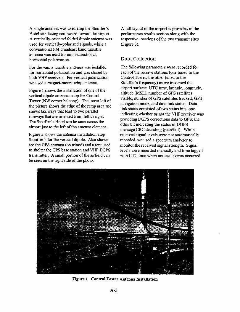
A singleantennawasusedatoptheStouffer'sHotelsitefacingsouthwardtowardtheairport.A vertically-orientedfoldeddipoleantennawasusedforvertically-polarizedsignals,whileaconventionalFM broadcastbandturnstileantennawasusedforomni-directional,horizontalpolarization.
Forthevan,aturnstileantennawasinstalledfor horizontalpolarizationandwassharedbybothVHFreceivers.Forverticalpolarizationweusedamagnet-mountwhipantenna.
Figure1showstheinstallationof oneof theverticaldipoleantennasatoptheControlTower(NWcornerbalcony).Thelowerleftofthepictureshowstheedgeof therampareaandshowstaxiwaysthatleadtotwoparaUelrunwaysthatareorientedfromlef_toright.TheStouffer'sHotelcanbeseenacrosstheairportjustto theleftof theantennaelement.
Figure2showstheantennainstallationatopStouffer'sfor theverticaldipole.AlsoshownaretheGPSantenna(ontripod)andatentusedtosheltertheGPSbasestationandVHFDGPSWansmitter. A small portion of the airfield can
be seen on the right side of the photo.
A full layout of the airport is provided in the
performance results section along with the
respective locations of the two transmit sites
(Figure 3).
Data Collection
The following parameters were recorded for
each of the receive stations (one tuned to theControl Tower, the other tuned to the
Stouffer's frequency) as we traversed the
airport surface: UTC time, latitude, longitude,
altitude (MSL), number of GPS satellites
visible, number of GPS satellites tracked, GPS
navigation mode, and data link status. Data
link status consisted of two status bits, one
indicating whether or not the VHF receiver wasproviding DGPS corrections data to GPS; the
other bit indicating the status of DGPS
message CRC decoding (pass/fail). While
received signal levels were not automatically
recorded, we used a spectrum analyzer to
monitor the received signal strength. Signal
levels were recorded manually and time taggedwith UTC time when unusual events occurred.
Figure 1 Control Tower Antenna Installation
A-3
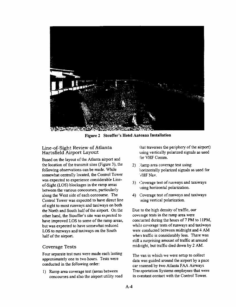
Figure 2 Stouffer's Hotel Anlenna Installation
Line-of-Sight Review of AtlantaHartsfield Airport Layout
Based on the layout of the Atlanta airport and
the location of the transmit sites (Figure 3), the
following observations can be made. While
somewhat centrally located, the Control Tower
was expected to experience considerable Line-
of-Sight (LOS) blockages in the ramp areas
between the various concourses, particularly
along the West side of each concourse. The
Control Tower was expected to have direct line
of sight to most runways and taxiways on boththe North and South half of the airport. On the
other hand, the Stouffer's site was expected to
have improved LOS to some of the ramp areas,
but was expected to have somewhat reducedLOS to runways and taxiways on the South
half of the airport.
Coverage Tests
Four separate test runs were made each lasting
approximately one to two hours. Tests were
conducted in the following order:
l) Ramp area coverage test (areas between
concourses and also the airport utility road
_:hat traverses the periphery of the airport)
using vertically polarized signals as usedfor VHF Comm.
2) i(amp area coverage test using]horizontally polarized signals as used forVHF Nav.
3) _2overage test of runways and taxiways
using horizontal polarization.
4) Coverage test of runways and taxiways
_lsing vertical polarization.
Due to the high density of traffic, our
coverage tests in the ramp area were
conducted during the hours of 7 PM to 11PM,
while coverage tests of runways and taxiways
were conducted between midnight and 4 AM
whea traffic is considerably less. There was
still a surprising amount of traffic at around
mi& light, but traffic died down by 2 AM.
The van in which we were setup to collect
data was guided around the airport by a pace
car manned by two Atlanta FAA Airways
TrarLsportation Systems employees that werein constant contact with the Control Tower.
A-4
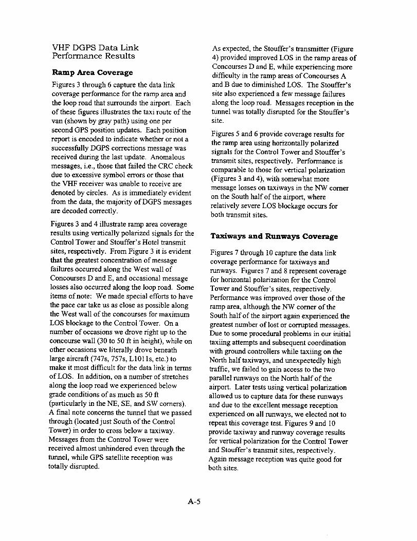
VHF DGPS Data LinkPerformance Results
Ramp Area Coverage
Figures 3 through 6 capture the data link
coverage performance for the ramp area and
the loop road that surrounds the airport. Each
of these figures illustrates the taxi route of the
van (shown by gray path) using one per
second GPS position updates. Each position
report is encoded to indicate whether or not a
successfully DGPS corrections message was
received during the last update. Anomalous
messages, i.e., those that failed the CRC check
due to excessive symbol errors or those thatthe VHF receiver was unable to receive are
denoted by circles. As is immediately evident
from the data, the majority of DGPS messages
are decoded correctly.
Figures 3 and 4 illustrate ramp area coverage
results using vertically polarized signals for theControl Tower and Stouffer's Hotel transmit
sites, respectively. From Figure 3 it is evident
that the greatest concentration of message
failures occurred along the West wall of
Concourses D and E, and occasional message
losses also occurred along the loop road. Some
items of note: We made special efforts to have
the pace car take us as close as possible alongthe West wall of the concourses for maximum
LOS blockage to the Control Tower. On a
number of occasions we drove right up to the
concourse wall (30 to 50 ft in height), while on
other occasions we literally drove beneath
large aircraft (747s, 757s, L101 ls, etc.) tomake it most difficult for the data link in terms
of LOS. In addition, on a number of stretches
along the loop road we experienced below
grade conditions of as much as 50 ft
(particularly in the NE, SE, and SW comers).
A final note concerns the tunnel that we passed
through (located just South of the Control
Tower) in order to cross below a taxiway.
Messages from the Control Tower were
received almost unhindered even through the
tunnel, while GPS satellite reception was
totally disrupted.
As expected, the Stouffer's transmitter (Figure
4) provided improved LOS in the ramp areas of
Concourses D and E, while experiencing more
difficulty in the ramp areas of Concourses Aand B due to diminished LOS. The Stouffer's
site also experienced a few message failures
along the loop road. Messages reception in the
tunnel was totally disrupted for the Stouffer'ssite.
Figures 5 and 6 provide coverage results for
the ramp area using horizontally polarized
signals for the Control Tower and Stouffer's
transmit sites, respectively. Performance is
comparable to those for vertical polarization(Figures 3 and 4), with somewhat more
message losses on taxiways in the NW comer
on the South half of the airport, where
relatively severe LOS blockage occurs forboth transmit sites.
Taxiways and Runways Coverage
Figures 7 through 10 capture the data link
coverage performance for taxiways and
runways. Figures 7 and 8 represent coveragefor horizontal polarization for the Control
Tower and Stouffer's sites, respectively.
Performance was improved over those of the
ramp area, although the NW comer of the
South half of the airport again experienced the
greatest number of lost or corrupted messages.Due to some procedural problems in our initial
taxiing attempts and subsequent coordination
with ground controllers while taxiing on the
North half taxiways, and unexpectedly hightraffic, we failed to gain access to the two
parallel runways on the North half of the
airport. Later tests using vertical polarization
allowed us to capture data for these runways
and due to the excellent message reception
experienced on all runways, we elected not to
repeat this coverage test. Figures 9 and 10
provide taxiway and runway coverage resultsfor vertical polarization for the Control Tower
and Stouffer's transmit sites, respectively.
Again message reception was quite good forboth sites.
A-5

A-6
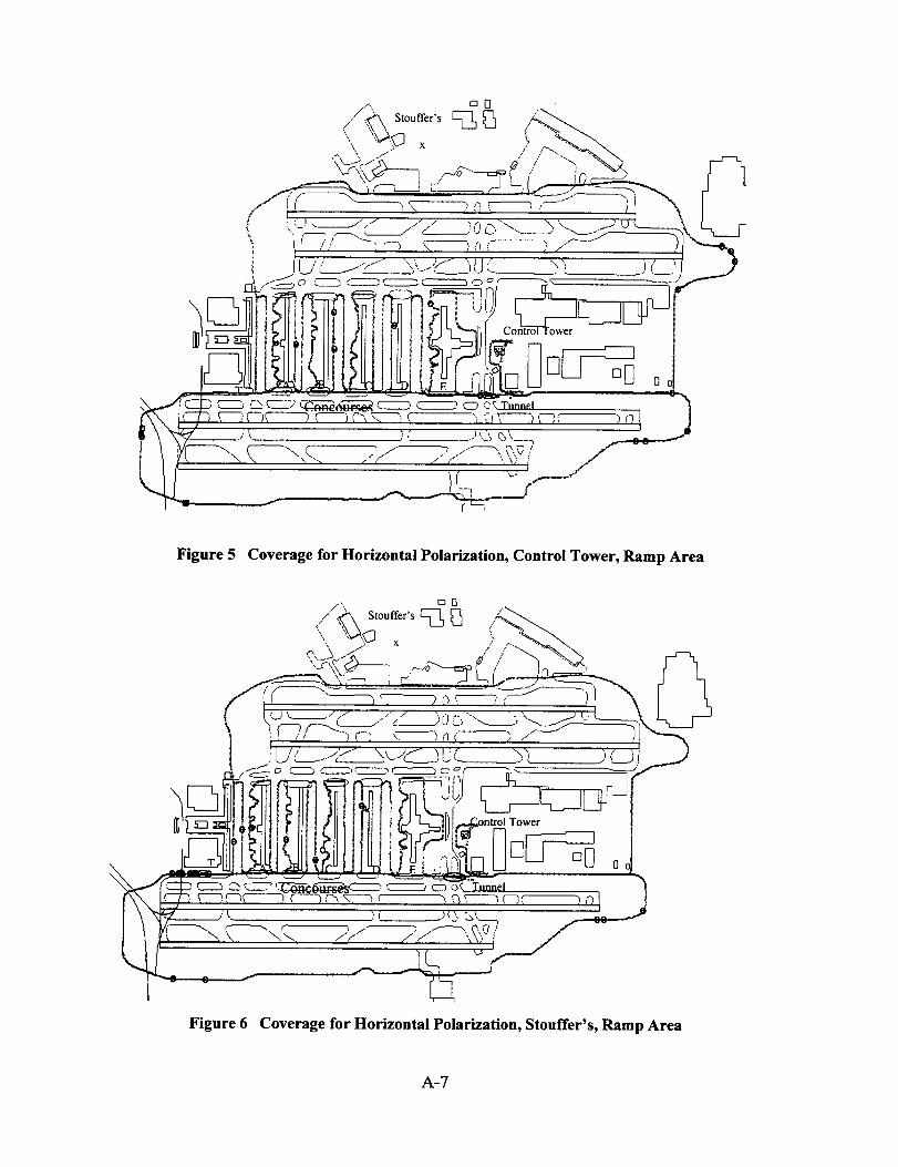
Figure 5 Coverage for Horizontal Polarization, Control Tower, Ramp Area
)\
Tower
i
Figure 6 Coverage for Horizontal Polarization, Stouffer's, Ramp Area
A-7

Stouffer's
'\, ._"+" X / I "! "_'_. _'_
_Q©,---_ .__'----=_<,,"! I__---?..jTY-_-I_L_:___-J_bt___)_'_--_
l i // -),,f-) m )_)_ .....> / - _I
Ix-, ,__._.=.__ _ _, ]!(]/ _ ._ !
t • 7 \___L_/' c._.___' C____j 7 _;-c _.'P CLO O_ Tunnel
t.+......... j=:t.............. '.............................)':{_.................'"" _G_'_ ............................
4It k '-, -,,"-_ / _" x r _i,.' "...................................................................................T"¢.................x_
Figure 7 Coverage for Horizontal Polarization, Control Tower, Runways and Taxiways
Stouffcr's
Figure 8 Coverage for Horizontal Polarization, Stouffer's, Runways and Taxiways
A-8

Stouffer's
X
Figure 9
Tower
Tunnel
Coverage for Vertical Polarization, Control Tower, Runways and Taxiways
\
Figure 10
Stouffer's
X
Tunnel
Tower
I
Coverage for Vertical Polarization, Stouffer's, Runways and Taxiways
A-9
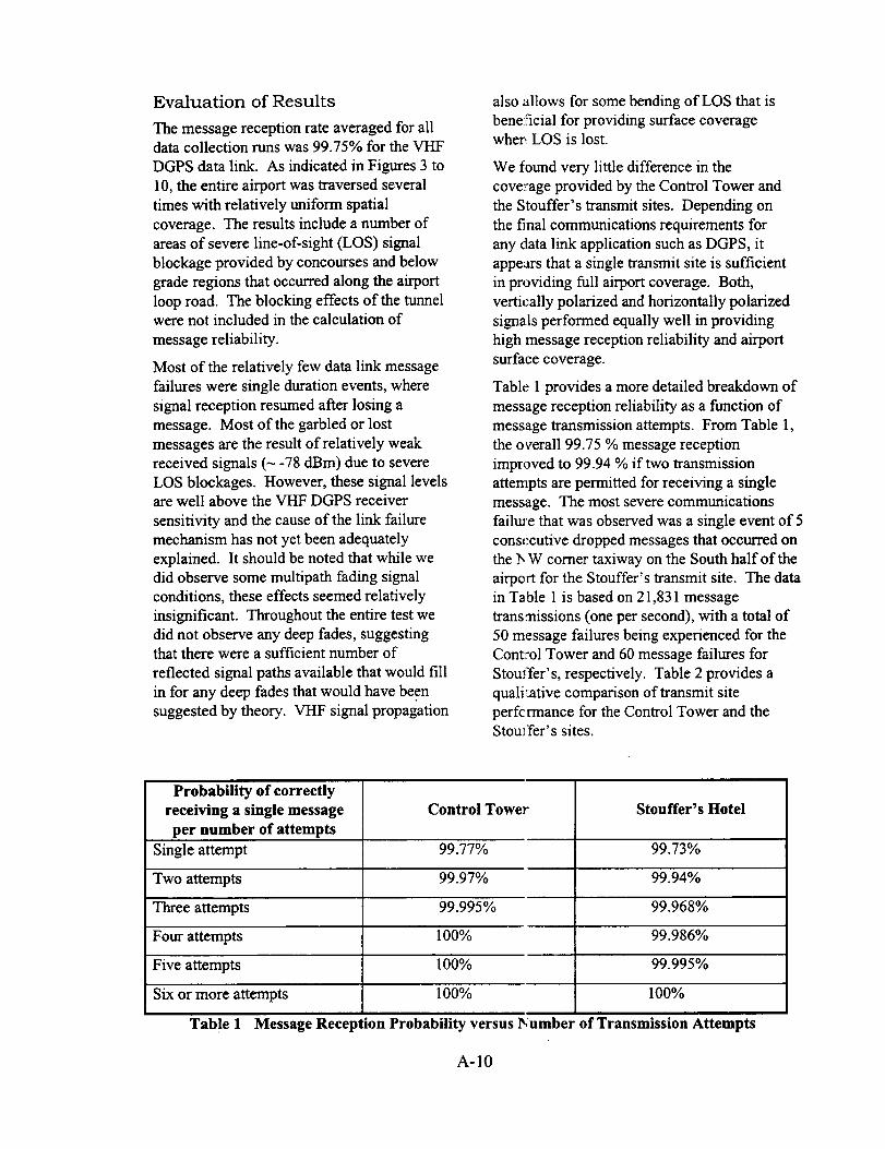
Evaluation of Results
The message reception rate averaged for alldata collection runs was 99.75% for the VHF
DGPS data link. As indicated in Figures 3 to
10, the entire airport was traversed several
times with relatively uniform spatial
coverage. The results include a number of
areas of severe line-of-sight (LOS) signal
blockage provided by concourses and below
grade regions that occurred along the airport
loop road. The blocking effects of the tunnelwere not included in the calculation of
message reliability.
Most of the relatively few data link message
failures were single duration events, where
signal reception resumed after losing a
message. Most of the garbled or lost
messages are the result of relatively weak
received signals (_ -78 dBm) due to severe
LOS blockages. However, these signal levelsare well above the VHF DGPS receiver
sensitivity and the cause of the link failure
mechanism has not yet been adequately
explained. It should be noted that while we
did observe some multipath fading signalconditions, these effects seemed relatively
insignificant. Throughout the entire test we
did not observe any deep fades, suggestingthat there were a sufficient number of
reflected signal paths available that would fill
in for any deep fades that would have beensuggested by theory. VHF signal propagation
also allows for some bending of LOS that is
beneficial for providing surface coveragewhere,LOS is lost.
We found very little difference in the
coverage provided by the Control Tower and
the Stouffer's transmit sites. Depending on
the final communications requirements for
any data link application such as DGPS, it
appears that a single transmit site is sufficient
in providing full airport coverage. Both,
vertically polarized and horizontally polarized
signals performed equally well in providing
high message reception reliability and airport
surface coverage.
Table 1 provides a more detailed breakdown of
message reception reliability as a function of
message transmission attempts. From Table 1,
the overall 99.75 % message reception
improved to 99.94 % if two transmissionattempts are permitted for receiving a single
message. The most severe communications
failure that was observed was a single event of 5
consecutive dropped messages that occurred on
the lx W comer taxiway on the South half of the
airport for the Stouffer's transmit site. The data
in Table 1 is based on 21,831 message
transmissions (one per second), with a total of
50 message failures being experienced for the
Control Tower and 60 message failures for
Stouffer's, respectively. Table 2 provides a
quali'ative comparison of transmit site
perfc rmance for the Control Tower and theStouffer's sites.
Probability of correctly
receiving a single message Control Tower Stouffer's Hotel
per number of attempts
Single attempt 99.77% 99.73%
Two attempts 99.97% 99.94%
Three attempts 99.995% 99.968%
Four attempts 100% 99.986%
Five attempts 100% 99.995%
Six or more attempts 100% 100%
Table I Message Reception Probability versus Dumber of Transmission Attempts
A-10
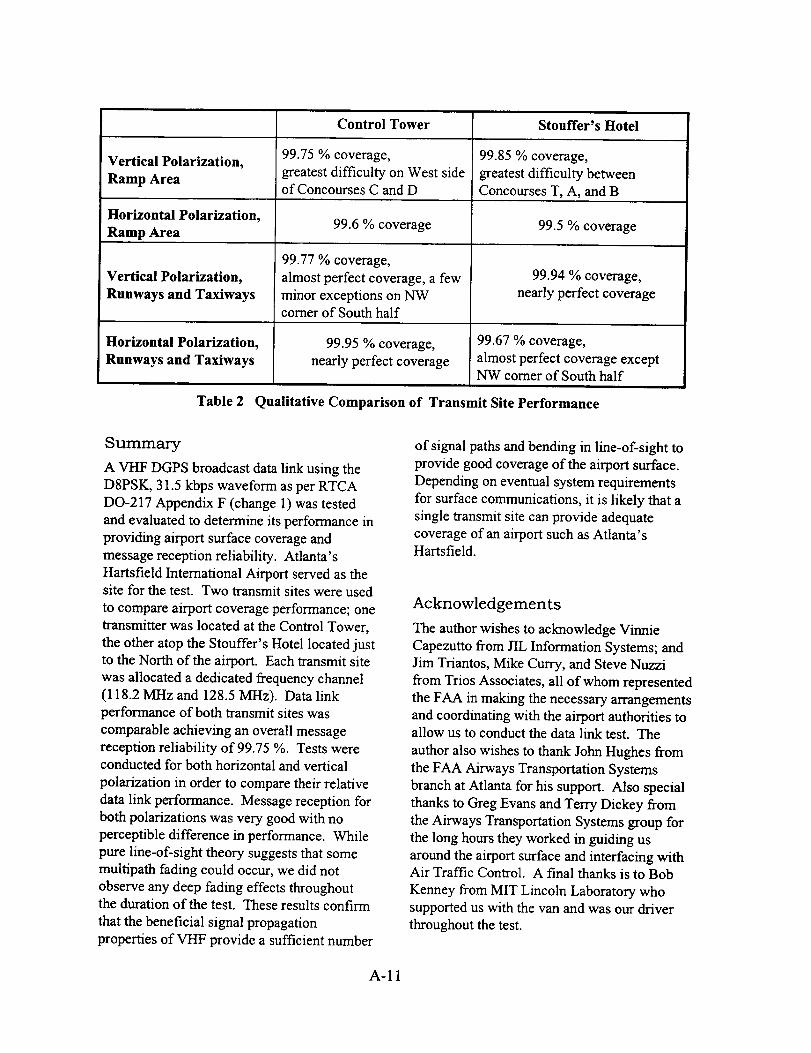
Control Tower Stouffer's Hotel
Vertical Polarization, 99.75 % coverage, 99.85 % coverage,
Ramp Area greatest difficulty on West side greatest difficulty betweenof Concourses C and D Concourses T, A, and B
Horizontal Polarization, 99.6 % coverage 99.5 % coverageRamp Area
Vertical Polarization,
Runways and Taxiways
Horizontal Polarization,
Runways and Taxiways
Table 2
99.77 % coverage,
almost perfect coverage, a few
minor exceptions on NWcomer of South half
99.95 % coverage,
nearly perfect coverage
99.94 % coverage,
nearly perfect coverage
99.67 % coverage,
almost perfect coverage exceptNW comer of South half
Qualitative Comparison of Transmit Site Performance
Summary
A VHF DGPS broadcast data link using the
D8PSK, 31.5 kbps waveform as per RTCA
DO-217 Appendix F (change 1) was tested
and evaluated to determine its performance in
providing airport surface coverage and
message reception reliability. Atlanta's
Harts field International Airport served as thesite for the test. Two transmit sites were used
to compare airport coverage performance; one
transmitter was located at the Control Tower,
the other atop the Stouffer's Hotel located just
to the North of the airport. Each transmit site
was allocated a dedicated frequency channel
(118.2 MHz and 128.5 MHz). Data linkperformance of both transmit sites was
comparable achieving an overall messagereception reliability of 99.75 %. Tests wereconducted for both horizontal and vertical
polarization in order to compare their relative
data link performance. Message reception for
both polarizations was very good with no
perceptible difference in performance. While
pure line-of-sight theory suggests that some
multipath fading could occur, we did not
observe any deep fading effects throughoutthe duration of the test. These results confirm
that the beneficial signal propagation
properties of VHF provide a sufficient number
of signal paths and bending in line-of-sight to
provide good coverage of the airport surface.
Depending on eventual system requirements
for surface communications, it is likely that a
single transmit site can provide adequatecoverage of an airport such as Atlanta'sHartsfield.
Acknowledgements
The author wishes to acknowledge Vinnie
Capezutto from JIL Information Systems; and
Jim Triantos, Mike Curry, and Steve Nuzzi
from Trios Associates, all of whom represented
the FAA in making the necessary arrangementsand coordinating with the airport authorities toallow us to conduct the data link test. The
author also wishes to thank John Hughes from
the FAA Airways Transportation Systems
branch at Atlanta for his support. Also special
thanks to Greg Evans and Terry Dickey from
the Airways Transportation Systems group for
the long hours they worked in guiding us
around the airport surface and interfacing withAir Traffic Control. A final thanks is to Bob
Kermey from MIT Lincoln Laboratory whosupported us with the van and was our driver
throughout the test.
A-11


Appendix B
LVLASO GPS I Data Link Pallet
Interfaces and Schematics

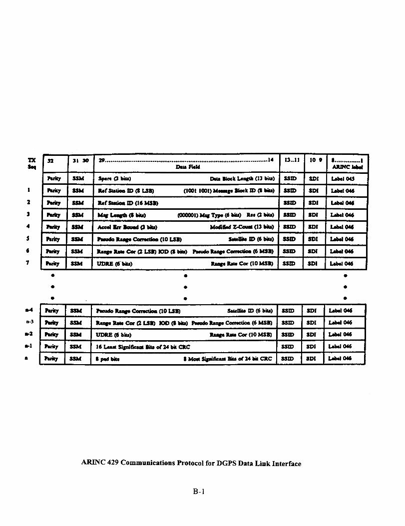
q_S,q
I
2
$
4
$
6
7
n-3
n-2
s-I
It
n :31 3O
Nlbf
SSH
SSM
SSld
SS)d
_*_**********************_********_**_**_******_***************_*********_*_*****_4
DaJ_eM13..11
_mm 0 l_u) lOummock lavish (1:3bits) SSID
l_f_ ID OBLSB) (I001IGOI)Mamp Block ID (11Id*s) UI_
i_fsmim ID (16 bISB) UZD
Jb_rtme_(stJ_u) (eoeOOl)S_s_(6_u) Jt,,(2_) ssm
Amd r_ _md 0 _i) j,_nr_odz.c.oum(13_) ssID
I_mdo _ Commim (10 [.,S_ _l_ ID (6 blu) _dD
]tm_nm, C_GLSn)JODCStl) emJdommseCommim(6MSn) SSlD
trDRE (W*bJu) hap _ Cot (I0 MSB) SS[D
Q
_ _ (10 um _ m (6b_.) _m
P._pn_Coc(2L.Sl0 X)D(Sblt,) PmdommseCms.cs_(6MStr) SSZD
UDRE (6 bit,) IbmZ* ]biteCo,' (10 M.S_ SSiD
16 _ SilpsifmJmi_ ot"24 bit CRC SSID
8 ped blm 8 MornSiipMGr.alBiw o( 24 I_t CRC SSID
10 9
SDI
$DI
$D!
SDi
SD!
SD[
SDi
SD!
SDI
SD[
SD!
SDI
SD[
8******°*****N|
_UNC IdJd
L,d_ 0t5
L,lbel 046
L,dJet046
Ldlel 0_
Ldlel 0_
L,ibel 046
l..bel 046
_bel 0_
L,d_ 046
Lsbd 046
L,llbei046
ARE_C 429 Communications Protocol for DGPS Data Link Interface
B-1

o 1 •
lJ"i "
i,
i'
"ii
IiL
i"
zi
I + Ii
i;_ i !
I I1 I, _,llllf
i -' i
ILL------_----_it i I :
'_,iiiI i.
.El!
|i
2
J
!iI I
1,iill_
I! i tti I.
g 1
i+" I +_._,-, I
I i
t ii
it !
"I'i'i!_i -'
iJii
; I 1i
i ! !
!
Ii
i$I9
1
6!
<>+--_<'-_/ I!
3,[I $ I
iii
!!!
ili'!-t-!-,l*tmt_r"<+"l ! i ,_
I ,---,t -'i'i'i'l
I
II
!i*i
I
illI
,,_;.-tel.. i_
."A'i
i ji
-I_ii,.i I-IIi. ' i
:: _il_i
ii
,i
il+!
il
I
B-2

UJl-Ul)-1/1
Vli
Ula0Z
0
_1
.J
-I
0.
!gZ
<
I
Ii
Im
!1
I
B-3

J_..
l_iiKlll' MM ItlMIfMHIl!
| .'!! :
= !II --
t i ; =
| °I --
ig
!
I+ ,'
iJii______ 1 _
! ,:lmi!i,, 1, I_.t!'t
,,.,...!' I°!
i_,iiii,','_!-i-_:'_'_'L ""_. i'h: '_,,| ,". I t:, I I1_
|- +
-I .... _-
'I_I_ +
i}| ::_ _
!
il-
+,I+m l
T ii
,,!
I i
i,
i iI' ii,
r
iii _i
I! '+1
s i s
,-........ _I ............ "_'_"............ "i........................... "_' -" I I ,
._ !! .-- , ,. -_ . _ .I. ,,, ,:_ ,I,]-_.!-,.i| i _ _ +ss -. =. t i ,;;i !_
_ :._ -_ .-' < ,_ ,.* ,t.
il,.......................................................................... +
_tus_
0-{ liii _
_,,'+--I_iiiii
I
]3-4

-t .........................|:i |=
!
44
Id
I: iii .zd
.....ii...............i
i
!
{!:J_i•
!!
|
T
I iilii _I i__ ''
v
!ii_r--
[ E
i
iiI
| iJ i
I
I ri tit
iE _r
l! 'i ,_hl
!,i!
i!,,
t
!II ' "l -'L
I_-_..._i ,,F"
]fill'. _,
_ || 1
I ,,2
I
I| -
| ' _
(
| iiil -i _[ i ",dO
|U --
i _1_ ,I
I
B-5
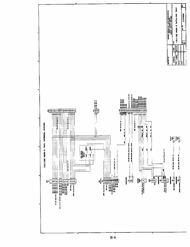
ie: _ i
_Oil
Iii
|
,Ltl!
' ii_ t!
!i
I
IB-6
Appendix C
Mode-S Pallet Interfaces and Protocols


Controller Pilot Data Link Communications (CPDLC) Data Link
for
NASA LVLASO Demonstration
Interface Control Document
C-!

1.0 _oduc_on
This document provides an overview of the CPDLC interfaces and describes the Mode-S data link message
formats and protocols that support CPDLC data link for the NASA LVLASO demonstration at Atlanta.
Figure I identifies the interfaces of the various sub-system components of the CPDLC data link system.
Sub-system components consist of the Controller Interface (CI), being developed by St. Cloud StateUniversity; the ATIDS Master Work Station (MWS) and ATIDS Receivers/Transmitters (R/Ts) that are
provided by Cardion; the Mode-S transponder and Airborne Data Link Processor (ADLP) provided by
RockweU-Collins, and the NASA I/O Network and Flight Test Computer.
From Figure l, Interface 'A' between the Control Interface and the ATIDS MWS is documented by [I].
[l ] describes the application data interface, physical layer RS-232/modem interface and associated
communication protocols. CPDLC messages used in the LVLASO demonstrdtion are listed in [1,2].
Interfaces 'B' and 'C' are internal to ATIDS (Cardion) and Mode-S/ADLP (Rockwell-CoUins),
respectively, and will thus not be specified. Section 2 of this document describes Interface A* containedwithin the ATIDS MWS (see Figure 1), and Section 3 describes Interface 'D' located between the ADLPand NASA I/O Network.
t RS232, t ATIES
Controller Modem MWS
Interface A (Interface A*)
J
B
a) Ground Sub-System
ATIDS
Rn'(s)
_ Airborne _ARINC 42_ FO Network
Mode-S _ Data Link &
Transponder Processor Flight Test
C (ADLP) J AR.[NC 429 [ Computer
b) Airborne Sub-',_ystem
Figure 1 CPDLC Data Link System
2.0 A TIDS MWS - Mode-S Interface
While not explicitly shown in Figure 1, the ATIDS MWS is responsl_ole for an additional interface(Interface A*) that maintains the Mode-S communication pro:ocols with the airborne Mode-S
transponder/ADLP. This section describes the Mode-S conm_tmications protocols that must be supported
by the AT[DS MWS and the airborne Mode-S/ADLP for CPDLC data link. CPDLC data link for the
LVLASO demonstration uses the Mode-S Specific Protocol (_ISP) which is a subset of the Mode-SSpecific Services Protocols (MSSP) [3]. Protocols for uplink and downlink CPDLC messages aredescribed.
C-2
2.1 Uplink CPDLC Messages - MSP Protocol
Uplink CPDLC messages are uansmitted using the Mode-S Specific Protocol (MSP). Depending on theoverall length of the CPDLC application message, messages are either encoded as Short Form MSP
Packets (for messages of 26 bytes or less) or as Long Form MSP Packets (for message lengths from 27
bytes to 159 bytes). For the LVLASO demonstration system, all CPDLC messages are less than 27 byteslong and thus only Short Form MSP Packets are required.
The data associated with Short Form MSP Packets is partitioned and inserted into the 56-bit MA subfield
(format shown below) of long (112-bit) Mode-S surveillance interrogations, which serve as the basic building
block for upHnk of MSP messages. The format of the 112-bit Mode-S surveillance interrogation usingUplink Formats (UF=20 or 21) is descn'bed first, followed by the encoding of Short Form MSP Packets.
2.1.1 Format of 112-bit Uplink CPDLC Mode-S Messages
Uplink CPDLC messages consist of long, 112-bit Mode-S interrogations using Uplink Formats UF=20 orUF=21. The message format of these interrogations is as follows:
I 'IPC:31R 'IO''IUF = Uplink Format (5-bit subfield);
SD: 16
PC* = ProtoCol (3-bit subfield);
RR* = Reply Request (5-bit subfield);
DI* = Designator, Identification (3-bit subfield)
SD = Special Designator (16-bit subfield)
MA:56 [ AP:24
All CPDLC uplink messages use either UF=20 (i.e.,
• I0100') for altitude requests or UF=21 (i.e., ' 10101 ") foridentity requests.
Always set to '000" for uplink messages in the LVLASO
demonstration (no change in transponder state).
Always set to '00000' for uplink messages in theLVLASO demonstration.
This subfield is used to identify the coding contained in
the SD subfield. Always set to '001' for uplink messagesin the LVLASO demonstration (indicates SD field
contains multisite information).
Coding of the SD subfield is as follows:
*Note:
SD Subfield Encoding
I
IIS:4 MBS:2 MES:3 [ LOS: 1
IIS= Interrogator Identifier (4-bit subfield)
MBS* = Multisite Comm-B Subfield (2 bits)
I RSS:2 ] TMS:4
This field is arbitrarily chosen to be
' 1000' for the ATIDS ground
interrogator in the LVLASOdemonstration.
(Note: The Atlanta groundinterrogator IIS code is '0110').
Always set to '00' for uplink
messages in LVI.ASO demonstration.
Encoding of PC, RIL DI and MBS subfields may be different for interrogations that are in response
to requests of air-initiated or multisite-directed downlink CPDLC messages by the aircraft; refer tosection 2.2 for details).
C-3

IVIES = Multisite ELM Subfield (3 bits)
LOS = Lockout Subfield (1 bit)
RSS = Reservation Status Subfield (2 bits)
Always set to '000' for LVLASO
demonstration (no ELM action).
Always set to '0' for LVLASOdemonstration
(no change in transponder all-call
reply lockout state).
Always set to '00' for uplink
messages in LVLASO demonstration
(no reservation status requests).
TMS = Tactical Message Subfield (4 bits) TMS encoding is as follows:
TMS Subfield Encoding
Spare: 1 1 LAS:3
The most significant bit of TMS is a spare bit.
LAS -- Linked Comm-A Subfield (3 bits)
LASVahie _
0 single segment
1 linked, 1'_ segment
2 linked, 2"a but not final segment
3 linked, 3cabut m,t final segment
4 linked, 4_ and final segment5 linked, 2_ and f-a3al segment
6 linked, 3"_and final segment
7 unassigned.
Note: For the LVLASO demonstration, the maximum length uplink CPDLC
message is expected to require two segments. Encoding of this message
will require two consecutive uplink UF=20 or UF--21 messages with LAS= 1 for the initial segment ard LAS = 5 for the second and final segment.
Should a longer CPDLC me:sage be required in the future, LAS encodingwill be as defined above.
Most uplink CPDLC messages require only a single segment, i.e., LAS =O.
MA = Message, Cornm-A (56-bit subfield) The MA subfield is used to transport uplink Short Form
MSP Packet clata, which contains uplink CPDLC
application data. Encoding of Short Form MSP Packetdata is descr_ bed in Section 2.1.2.
AP = Address/Parity (24-bit subfield) Contains par:ty overlaid on the 24-bit ICAO address for
the aircrafL Occurs at end of all Mode-S uplink and
downlink messages (except DF=I 1).
C-4
2.1.2 Format of Short Form MSP Packets (Uplink)
CPDLC application data is inserted into Short or Long Form MSP Packets. Since CPDLC messages used in the
LVLASO demonstration are relatively short they will always be in the form of Short Form MSP Packets. The
Short Form MSP Packet is partitioned and inserted into successive 56-bit MA subfields of UF=20 or UF=21
interrogations. The format of an uplink Short Form MSP Packet for the LVLASO demonstration is as follows:
Short Form MSP Packet Encoding (Uplink)
DP: 1 MP: I
DP = Data Packet type (l-bit subfield)
MP = MSP Packet type (l-bit subfield)
M/CH = MSP CHannel # (6-bit subfield)
Fill = Fill bits (0-bits)
UD = User Data (v-bit subfield)
Note I:
Note 2:
Always set to '0' for uplink messages in the LVLASOdemonstration.
Always set to '0' for the LVLASO demonstration
(indicates a Short Form MSP Packet).
Always set to '000110' for the CPDLC data link application in
the LVLASO demonstration (i.e., CPDLC uses MSP channel 6).
No fill bits are required for uplink CPDLC messages.
Application data for CPDLC uplink messages is inserted into this
field. The length of data is variable depending on the specific
uplink message. Since 6-bytes of application data are inserted ata time into the MA subfield for each uplink interrogation (recaU
that the fast byte of the MA subfield is a control byte containingDP:I, MP:I and M/CH:6), application data must be zero padded
to provide an integer multiple of 6-byte data blocks. The control
byte is always the fwst byte in the MA field for uplink messagesin the LVLASO demonswation.
Note: As currently defined, the Controller Interface transfers 6-
byte data segments (of a CPDLC message) at a time to the ATIDS
MWS [l]. The ATIDS MWS is then responsible for formattingthe collection of these segments into the proper sequence of Mode-
S uplink interrogations OJ'F=20 or UF=2 I).
In response to UF=20 or UF=21 uplink CPDLC interrogations, the airborne Mode-S transponderwiU automatically acknowledge receipt of an interrogation with a downlink reply. This will be
referred to as a "transponder acknowledgment" or XPDR ACIC The ATIDS MWS must monitor
successful receipt ofXPDR ACKs to any of its CPDLC uplink messages. For a two segment UF=20
or UF=21 uplink message, the ATIDS MWS must verify that two XPDR ACKs were received that
confirm transponder reception of both segments (i.e., the entire message). Alternately, the ATIDSMWS could report back to the Controller Interface the XPDR ACKs on a per segment basis, with
the Controller Interface assuming responsibility for monitoring whether messages were
acknowledged by the transponder.
Some CPDLC uplink messages require the pilot to respond with a dowulink CPDLC message. This
acknowledgment or response will be referred to as a PILOT ACK and should not be confused with a
XPDR ACK. PILOT ACKs occur at the application layer while XPDR ACKs occur at the physical /data Link layer.
When the ADLP receives a dowulink message from the pilot (in response to a previous received
uplink message), the ADLP generates either an air-initiated or a multi-site directed dowulink CPDLCmessage and transfers/t to the Mode-S wansponder for transmission. Downlink message protocols
associated with the ADLP/Mode-S transponder and the ATIDS M'WS are described in section 2.2.
C-5

2.1.3 Encoding Examples of Uplink CPDLC Messages
This section provides two examples ofuplink CPDLC messages; one requiring only a single uplink
interrogation and a second example where two uplink interrogations are needed.
2.1.3.1 Single-Segment Uplink CPDLC Message Example
"Maintain Altitude" uplink message
Encoding of this message is as follows (per RTCA DO-219):
Preamble Message ID Element ID Altitude Choice Altitude Value Pad00 001001 00010011 000 0010101 III00 00000000000000000
This application data encodes into: 09 13 05 78 00 00 in hexadecimal format. Note that the data is
zero-padded to 6 bytes. The Controller Interface provides this data
to the ATIDS MWS [I].
The 56-bit MA subfield thus encodes to: 06 09 13 05 78 00 00
where the leading byte is (DP = "0", MP = '0', and M/CH ='0001 I0' or 06 H).
The full encoding of the 112-bit uplink interrogation is as foll,_ws:
UF:5 PC:3 RR:5 DI:3 SD:I6
IIS:4 MBS:2 MES:3 LOS:I RSS:2 Spare:l LAS:3I0100 000 00000 001 1000 00 000 0 (J0 0 000
This encodes to: A0 01 80 00 06 09 13 05 78 00 00 (AP:24 must also be appended).
Note I: LAS = '000' indicates that this uplink CPDLC message is only a single segment message.
Note 2: This example assumed a UF=20, which also provides altitude data in the transponder reply.UF=21 could also be used ff an identity reply is requested.
2.1.3.2 Two-Segment Uplink CPDLC Message Example
"Contact ATL Tower 119.5" uplink message
Encoding of application message is as follows (per RTCA DO-219):
Field Name
Preamble
Message ID
Element ID
ICAOunimame
MA:56
(already in hex)(06 09 13 05 78 O0 00)
Value
)00'
'O00011'
'Olll OlOI"
'I0'
'I000001'
'lOIOIlO'
'I001100'
'0000000'
'010'
Comment
Arbitrarily selected value of message ID counter
Uplink message #117
ICAC facilitydesignation (2-bit flag)
ICACfacilitydesignation (1" character = A)
" (2 "_character = T)
" (3 '_ character = L)
" (4 _ character = 'null')
ICAC,facilityfunction ('Tower')
C-6

Frequency
Pad
'0I' Frequency Choice = 'fzequencyvhf'
'00010011I000100' FrequencyValue =' 119.500MHz'
'00 0000 0000 0000 0000 0000 0000 0000' Applicationdataispadded withzerostofillan
integermultipleof6-bytesblocks,where each 6-
byteblockrepresentsa segment ina ShortForm
MSP Packet).
Concatenating these fields and converting them into hexadecimal format results in the following encoding:
03 75 A0 D4 98 01 22 71 00 00 00 00H Note: The appLicationmessage consistsof 12
bytesofdatawhich isprovidedby theControllerInterfacetotheATIDS MWS in
two separate 6-byte data transfers [1].
The 56-bit MA subfields encodes to: 06 03 75 A0 D4 98 01 (MA subfield for segment#I)
06 22 71 00 00 00 00 (MA subfield for segment #2)
where the leading byte in each segment is 06 H
(DP = '0', NIP = '0', and M/CH --- '0001 I0').
The full encoding of the two I 12-bit uplink interrogation required for uplink of"Contact ATL Tower119.5" is as follows:
UF:5 PC:3 RR:5 DI:3 SD:16
IIS:4 MBS:2 MES:3 LOS:I RSS:2
10100 000 00000 001 1000 00 000 0 00
This encodes to: A0 01 80 01 06 03 75 A0 D4 98 01
MA:56
Spare:l LAS:3 (already in hex)
0 001 (06 03 75 A0 IM 98 01)
(AP:24 must also be appended).
Interrogation #2:
UF:5 PC:3 RR:5
I0100 000 00000
This encodes to:
DI:3 SD:16 MA:56
IIS:4 MBS:2 MES:3 LOS:I RSS:2 Spare:lLAS:3 (already in hex)
001 1000 00 000 0 00 0 101 (06 22 71 00 00 00 00)
A0 01 80 05 06 22 71 00 00 00 00 (AP:24 must also be appended).
Note 1: LAS = '001' for interrogation #1 indicates that this upLink CPDLC message is the first segment ofa series of linked segments. LAS = '101' for interrogation # 2 indicates that this is the second and
final segment of the series of linked messages.
Note 2: This example assumed a UF=20, which also provides altitude data in the transponder reply.UF=21 could also be used if an identity reply is requested.
C-7
2.2 Downlink CPDLC Messages - MSP Protocol
This section describes the MSP protocol used between the ADLP and the ATIDS MWS for downlink
CPDLC messages.
For the LVLASO demonstration, downlink CPDLC messages are actuated at the pilot interface and FlightTest Computer and are transferred to the ADLP via the NASA I/O network using an ARINC 429 bus and
using a modified Williamsburg ARJNC 429 file transfer protocol. This protocol and the format of the data
file of the downlink message are described in section 3.2. Using the downlink data provided by the I/O
network, the ADLP uses the Mode-S Specific Protocol (MSP) to downlink CPDLC messages.
2.2.1 Overview of Mode-S Downlink (Comm-B) Messaging
Before descnbmg the specific message formats for downlink messages, it is useful to review the Mode-S
downlink (Comm-B) messaging protocol as it pertains to the LVLASO demonstration. Two types of
downlink transmissions are of particular interest for the LVLASO demonstration: 1) Downlink
transponder reply that is in response to an uplink CI'DLC message interrogation, thus providing a XPDR
ACK; 2) Downlink CPDLC message initiated by the pilot (either a request or status message, or a
reply/acknowledgment message that is in response to a previous uplink CPDLC message).
If the Mode-S transponder does not require dowrtlink transmission of a pilot-initiated CPDLC message at
the time an interrogation is received, the Mode-S transponder s_mply transmits a conventional surveillance
reply. However, ffa downlink CPDLC message needs to be transmitted, the Mode-S transponder includes
in the reply a notification to the ground interrogator (i.e., ATID3 MWS) that it has a downlink messagethat needs to be transmitted.
Note: When the ADLP has a multi-segment downlink message to be transmitted, it transfers each segment
to the transponder, where the transponder then stores the f_rst 56-bit segment in the air-initiated register(register 0) and stores the remaining segments in ground-initiated registers number 2, 3, and 4,
respectively. Once the complete message has been stored in these registers, the Mode-S transponder
provides a notification to the ground interrogator that a message is available for downlmk. It does this in
one of two ways:
1) "Air-initiated Comm-B" protocol
When transmitting a DF=I 1 (All-Call reply or squitter) or .'_DF=17 (extended squitter), the
transponder sets the CA (Capability) subfield to ' 111 ', whi:h indicates to the ground interrogator thatthe transponder has a message waiting to be downlinked. Upon detecting the CA = 7 condition, the
ground station schedules a UF = 4, 5, 20 or 21 interrogation to the Mode-S transponder in order to
read the DR (Downlink Request) subfield in the DF = 4, 5, 20 or 21 transponder reply. DR indicatesthe type of downlink message (if any) that is stored in the transponder for eventual downlink.
2) "Multi-site Directed Comm-B" protocol
Independent of whether or not the wausponder has set the CA subfield in previously sent DF=I 1 or
DF=I 7 squitters, the Mode-S transponder also informs the ground interrogator of a Comm-B request
by setting the DR subfield in DF = 4, 5, 20, or 21 replies to "00001' or '00011', which indicate a'request to send Comm-B message'.
Note: DR = '00011' also indicates that TCAS information is available. However, since the Mode=S
aircraft installation will be independent of TCAS for the LX_LASO demonstration, this DR code willnotoccur.
C-8

Upon detecting a DR = '00001' or '0001 I' in the transponder reply, the ground interrogator sends a UF = 4,
5, 20 or 21 interrogation with RR = ' 1 0000' and DI = '001' to extract the fhst segment of the Comm-B
downlink message (which is stored in the air-initiated register in the transponder). DI = '001' provides the
transponder with multi-site information (i.e., the Interrogator Identifier Subfield, HS, which is located in the
SD subfield). The transponder includes the fLrSt segment of the dowulink message stored in the air-initiated
register in the MB:56 subfield of the corresponding DF=20 (if UF=4 or 20) or DF=21 (ifUF=5 or 21) reply.
The transponder continues to set the DR subfield to '00001' or '0001 I' until the interrogator closes out thedownlink message.
Contained in the MB subfield in the initial downlink segment is the two-bit LBS (Linked Comm-B) subfield
which indicates the length of the stored downlink message to be retrieved, i.e., message length ranges firoml to 4 segments. The ground interrogator uses this information to schedule the appropriate number of
additional interrogations. Encoding of the MB and LBS subfields is discussed in section 2.2.3 below.
Interrogations that solicit additional message segments for downlink consist of UF=4, S, 20 or 21
interrogations with RR set to ' I 0000', DI set to ' I 11' and RRS set to '0010', "0011 ', or '0100'. D I=' 111'
indicates that the SD subfield in the interrogation contains an extended data readout request of one of the
255 Mode-S data registers. The address of the extended data readout request consists of the 8-bit Comm-B
Definition Subfield, i.e., the BDS address. The RRS subfield, contained within the SD subfield, represents
the lower four bits of the BDS address, i.e. BDS2. The BDS1 address (upper four bits of BDS) is containedwithin the lower four bits of the RR subfield when the leading bit in RR =" 1 '. Thus RR=' I 0000' (also
DI =' 111') and RRS='0010', '0011 ', and '0100' represent BDS registers 2, 3 and 4, respectively.
Once all downlink message segments have been received, the ground interrogator closes out the downlink
message by sending a UF=4, 5, 20 or 21 with the PC (Protocol) subfield set to "100' (cancel Comm-B),
RR--'00000' and DI='001'. Alternately, the interrogator could set PC = '000' (no changes in transponder
state), RR = '00000', DI = '00i' (indicating that SD subfield contains multi-site information), with SDencoded as follows:
IIS -- '1000' (ATIDS interrogator ID), MBS = '10' (Comm-B Closeout), MES = '000', LOS -- '0'
(no lockout of All Calls), RSS -- '00", and TMS/LAS --- '0000'.
Notel: At this time, all of the CPDLC downlink messages that will be used in the LVLAS0
demonstration are sufficiently short to fit into a single dowulink message segment.
Note 2: Several references have been made regarding the encoding of the SD subfield in uplink
interrogations. SD is encoded in one of two ways, depending on whether DI='001' or' 111". SD
encoding is summarized as follows:
SD:16 for DI='O01'
SD Subfield Encoding
{ MES:3 [ gOS:l RSS:2 TMS:4IIS:4 ] MBS:2
$l_;16 for DI='I II'i
SD SubfieldEncoding
IIS:4 RRS:4 Spare:l l LOS:I _ Spare:2 TMS:4
Section 2. I. 1 discussed the encoding of SD (with DI='001') for typical interrogations. For theLVLASO demonstration, IIS is always set to '1000' for ATIDS; MBS--'00' in all cases except
"10' for a Comm-B Closeout; MES, LOS and RRS are always set to "00', "0' and '00',
respectively. TMS encoding is as descn'bed in Section 2.1.1.
C-9

For DI =' 111 ', SD encoding always uses HS =' 1000' and LOS='0 '. RRS represents the lower 4bits of the BDS address of the Mode-S registers. TM:; encoding is defined in Section 2.1.1.
Specific formats for the downlink messages (replies) issued by the Mode-S transponder are described in thenext section.
2.2.2 Format of Downlink CPDLC Mode-S Messages (Replies)
The Mode-S transponder uses a DF=4 or 5 (short 56-bit reply) or DF=20 or 21 (long 112-bit reply) in
response to uplink CPDLC interrogations. The message format of the DF=4 or 5 and DF=20 or 21 Mode-S
replies are as follows:
DF:5 FS:3 DR:5 UM:6 ID:13 (for DF--5,21)
DF = Dow_li_ Format (5-bit subfield);
MB:0 (for DF--4,5) orMB:56 (for DF=20,21) I AP:24 I
DF=4 replies are used for XPDR ACK_ to UF=20 (and UF=4)
interrogations (Le., when RR subfield = '0xxxx').
Alternately, DF=5 replies are Used for XPDR ACKs to UF=21
(and UF=5) interrogations (also when RR subfield = '0xxxx').
DF=20 or 21 are Used in response to UF = 4, 20 or 5, 21,
respectively, when the ground interrogator sets the RR
subfield to '10000', requesting downlink of a CPDLC
message segment in the MB:56 subfield. Note that the DF =
20 or 21 reply implicitly also provides a XPDR ACK. DFcoding is '00100', '00101', ' 10100' and ' 10101" for DF =
4, 5, 20, and 21, respectively.
FS = Flight Status (3-bit subfield);
DR = Downlink Request (5-bit subfield);
UM = Utility Message (6-bit subfield)
FS coding is as follows:
Code Aler'_: SPI Airborne on the _ound
0 no no yes no1 no no no yes
2 yes no yes no3 yes no no yes
4 yes yes either5 no yes either
6,7 not assigned
Set to '00006' when Mode-S transponder has no downlinkCPDLC mes:_ages that require transmission. Thus the reply
is simply a XPDR ACK to an interrogation.
When the Mode-S transponder requires a downlinktransmission ofa CPDLC message, it sets DR = '00001" or
"0001 l', whi:h is a 'request to send a Comm-B message'.
UM encodinl; is as follows:
UM Subfield Encoding
IDS:2 [ HS4
IDS (Identifier Designator Subfield_
0 = No information available
I = Comm-B reservation active
C-10

2=Comm-Creservation active
3 = Comm-D reservation active.
Due to the multi-site nature of Mode-S communications at Atlanta (i.e.,
separate ATIDS and Atlanta SSR interrogators), IDS will be set to '01' in
any reply where ATIDS is requesting downlink ofa CPDLC message..
Note:
AC = Altitude Code (13-bit subfield);
ID = Identification (I 3-bit subfield);
MB -- Message, Comm-B (56-bit subfield)
AP = Address/Parity (24-bit subfield)
IIS (Interrogator Identifier Subfield)
For LVLASO demonstration the ATIDS IriS = '1000'.
IIS for Atlanta's Secondary Surveillance Radar interrogator is '0110'.
Stores aircraft altitude information for DF--4 or DF=20
replies.
Stores aircraft ID (4096 code) in DF = 5 or DF = 21 replies.
MB is not used for DF = 4 or DF = 5 replies.
In the LVLASO demonstration, DF = 20 or DF = 21
replies use the MB subfield to transport Short Form MSP
Packet data, which contain downlink CPDLC application
data. Encoding of the MB subfield and the downlinkShort Form MSP Packet is descn_oed in Section 2.2.3.
Contains parity overlaid on the 24-bit ICAO address for
the aircraft. Occurs at end ofaU Mode-S uplink anddownlink messages (except DF--I 1).
2.2.3 Formatof MB Subfield and Short Form MSP Packets (downlink)
Encoding of the MB subfield ofDF = 20 or DF = 21 replies is as follows:
The first two bits in the initial MB subfield segment of a linked Comm-B downlink CPDLC message
consist of the LBS subfield (Linked Comm-B Subfield). LBS coding is as follows:
LBS Meaning
0 Single segment downlink message
1 initial segment of a two-segment message
2 initial segment of a three-segment message3 initial segment of a four-segement message.
The LBS subfield indicates to the ground interrogator the length of the pending CPDLC downlink message
in terms of its number of segments that must be solicited via ground interrogations. The remaining 54 bits
available in the initial MB subfield are used to store application data that is stored in the format of a ShortForm MSP Packet (described below). Subsequent MB subfields of linked Comm-B messages allow all 56
bits to be used for Short Form MSP Packet application data.
The format of the Short Form MSP Packet for downlink CPDLC messages is identical to that used foruplink CPDLC messages with the exception of the Fill bit subfield; Fill:0 is used for uplink messages while
Fill:6 is used for downlink messages, i.e., downlink messages have 6 fill bits which are set to zero.
Short Form MSP Packet Encoding (Downl_)
DP:I MP:I I M/CH:6 FiU:6 I UD:v
DP = Data Packet Type (1-bit subfield); Always set to '0' for downlink messages in LVLASOdemonstration.
C-11

MP = MSP Packet Type (l-bit subfield);
M/CH = MSP CHannel number (6-bit subfield)
Fill = Fill bits (6-bit subfield)
UD = User Data (v-bit subfield)
Always set to '0' for LVLASO demonstration (indicates a
Short Form MSP Packet).
Always set to '0001 I0' for CPDLC message application in
LVLASO demonstration (i.e., CPDLC uses MSP channel 6).
6 fill bits are required for downlink CPDLC messages inLVLASO demonstration. Fill bits are set to zero.
Application data for CPDLC downlink messages is
inserted into this field. The length of data is variable
depending on the specific downlink message.
2.2.4 Encoding Example of a Downlink CPDLC Message
This section provides an example encoding of a downlink CPDLC message and the associated Mode-S
protocols. The sample message is the "Descending to 4500 ft" downlink message.
Encoding of this message is as follows (per RTCA DO-219):
Preamble Message ID Element I]3 Altitude Choice00 000101 000111 I0 000
Altitude Value Pad
000111000010 0
This application data encodes into: 05 IE 03 84 in hexadecimal format. This is the CPDLC
application data sent Jtom the NASA FO network to the ADLP.
Note that the data is zero padded by the Flight Test Computer to
fill any spare bits in the ARINC 429 data file (to the nearestARINC 429 data word). For this example, a single '0' pad bit is
required. Section 3.2 further discusses the interface protocolsbetween the NASA I/O network and the ADLP.
Upon receiving the downlink CPDLC message from the NASA FO network, the ADLP formats thedownlink message into the appropriate set of message segments using the Short Form MSP Packet format.
The resulting message encoding is as follows:
LBS:2 DP:I MP:I M/CH:6 FILL:6 UD:v
00 0 0 000110 000000 05 1E 03 84 00
which encodes into the following hexadecimal format that is inserted into the 56-bit MB subfield:
01 08 05 1E 03 84 00
(Note that the ADLP adds additional zero padding to the message to fill the 56-bit MB subfield).The full encoding of the 112-bit downlink CPDLC message is as follows:
DF:5 FS:3 DR:5 UM:6 AC:I3 orII):13 MB:56 (already inhex) (AP:24)1010x xxx 0001x 01 1000 xxxxxxxxx,v.xxx 01 08 05 IE 03 84 00 AP:24
C-12

2.2.5 Mode-S Interrogation / Reply Scenarios for the LVLASO Demonstration
The following exchanges between the ground interrogator (ATIDS) and the airborne Mode-S transponder /
ADLP should be expected in the LVLASO demonstration. Compatibility with the Atlanta SSR
interrogator in terms of the Interrogator ID Subfield (IIS) must be ensured.
I) ATIDS may send an All-Call Interrogation, i.e., UF = I I.
The Mode-S transponder replies with a DF = 1I. Ira downlink CPDLC message has been received by
the ADLP / Mode-S transponder, the transponder sets the CA subfield = 7 (i.e., ' I l I '), indicating thata message is available for downlink.
2) ATIDS sends a UF = 4, 5, 20 or 21 surveillance interrogation. UF = 4 or 5 are used for surveillance
interrogations only. UF = 20 or 21 are used ffan uplink CPDLC message is included in the
surveillance interrogation. For UF = 20 or 21, RR = '00000', DI = '001' (indicating that the SD
subfield contains multi-site information, MA contains the uplink CPDLC message using the ShortForm MSP Packet, with SD encoded as follows:
IIS = 'I000' (ATIDS interrogator ID), MBS = '00' (no Comm-B action), IVIES = '000', LOS = "0'
(no lockout of All Calls), RSS = '00', and TMS/LAS = '0000' (single segment message) or
'000 I' (first segment of two message segments), '0101' (second of two message segments).
The Mode-S transponder replies with a typical DF = 4 or 5 surveillance reply. If an uplink CPDLC
message was included, the ADLP processes the message and transfers the complete message to the
NASA I/O network once all segments are received. In the event a downlink CPDLC message has been
received by the ADLP / Mode-S transponder from the I/O network, the transponder sets the DR
subfield = '00001' or "0001 I', indicating a request for a downlink (Comm-B) message to the groundinterrogator. If no downlink request is needed, DR is set to '00000'.
3) DF = 11 or DF =17 squirters.
The Mode-S transponder will transmit occasional squitter messages. If a downlink CPDLC message
needs to be transmitted, the transponder sets CA = 7 ('111 '). The DF = 17 squirter also provides ADS-
B position reports for ADS-B surveillance by ATIDS.
When ATIDS receives an indication of an air-initiated Comm-B (CA = 7 in a DF=I I or 17) or a multi-site
directed Comm-B request (DR = '00001' or '0001 I' in a DF = 4, 5, 20 or 21 reply) ATIDS schedules a UF
= 4, 5, 20 or 21 with the RR subfield set to' I 0000', and the DI subfield = '001', which requests the
transponder to downlink the initial segment of the CPDLC message in the reply.
The Mode-S transponder, upon receiving the UF = 4, 5, 20 or 21 interrogation replies with a DF = 20 or 21
with DR = "00001 ', IDS (in UM subfield) -- '01' and IIS (in UM subfield) = ' I000' (which is the ATIDS
Interrogator ID). The MB subfield contains the LBS subfield and the Short Form MSP Packet data stored
in air-initiated Comm-B register (register 0). LBS = '00' indicates a single downlink message segment.
ATIDS upon receiving the downlink CPDLC message, closes out the downlink message by sending a UF --
4, 5, 20 or 21 with the PC subfield = 'I00' (cancel Comm-B), RR = '00000' and DI = '000'. Alternately, the
interrogator could set PC = '000' (no changes in transponder state), RR -- "00000", DI = '001' (indicating thatSD subfield contains multi-site information), with SD encoded as follows:
IIS = '1000' (ATIDS interrogator ID), MBS = 'I0' (Comm-B Closeout), MES = '000', LOS = '0' (nolockout of All Calls), RSS = '00', and TMS/LAS = '0000'.
Note: Recall that LVLASO downlink messages are only one segment long.
C-13

3.0 Mode-S ADLP - I/0 Network Interface
Tl_ssection describesthe interface between the Airborne Data Link Processor (ADLP) and the end user
CPDLC application located in the Flight Test Computer (via the FO Network). This interface is denoted as
Interface 'D' in Figure 1. The physical interface consists of dedicated uplink and downlink AR/NC 429
buses configured in the high-speed mode (100 K/-Iz). The data link layer uses a modified WilliamsburgAR/NC 429 file transfer protocol to uplink and downlink CPDLC messages. The following sections
discuss the uplink and downlink ARINC 429 fde transfer protocols, respectively.
3.1 Uplink CPDLC Message Transfer (ADLP to I/O Network)
Upon successfully decoding an uplink CPDLC message, the ADLP builds a message file that is transferred tothe I/O Network using ARINC 429 fde transfer protocols. Section 3.1.1 descn'bes the AR/NC file transfer
protocol. Section 3.1.2 describes the encoding of file data. Section 3.1.3 provides an uplink file transfer
example.
3.1.1 ARINC 429 File Transfer Protocol
The ARINC f'de Wansfer protocol is as follows: The ADLP transmits a Request-To-Send (RTS) AXINC 429
protocol word to prepare the I/O Network for a fde transfer. This is followed by a Start of Transmission
(STX) word and subsequently by a number of ARINC 429 D_ta Words. The file transfer concludes with anEnd-of-Transmission (EOT) word. Specific formats are described below:
RTS Protocol Word
3231 30292827262524232221 20 19 18 17 16 15 14 13 12 11 109 87654321
P 1 0 0 0 0 0 1 ( Destination Code )( Word Count )( SAL )
SOT Protocol Word
32 313029282726252423 222120 19 18 17 16 15 14 13 12 II 109 87 65432 1
P I I 0 ( GFI ) (File Sequence Number) ( LDU Sequence No. ) ( SAL )
3231302928272625242322212019181716151413 1211 1098 7654321
P 0 0 0 (LoByte3)( Byte2 )( Bytel )( SAL )
EstRDma.=W=o_O__
3231 3029282726252423222120 19 18 17 16 15 14 13 12 II 109876543 2 1
P 0 0 0 ( Byte5 )( Byte4 )(Hi Byte 3)( SAL )
Partial Data Word #3
32 31 30 29 28 27 26 25 24 23 22 21 20 19 18 1716 1514131211 10987654321
P 0 0 1 1 0 ! 1 ( Byte7 )( Byte6 )( SAL )
EOT Protocol Word
323130292827262524232221 201918171_ 15 14 13 12 11 10987654321
P I I I 0 0 0 x ( Checks ma )( SAL )
C-14

The contents of the fields are defined as follows:
I) Dest/nation Code Destination code for the UO Network = '0100101 I'.
2) Word Count Represents the number of ARINC 429 Words to be transferred
following the RTS protocol word.Word Count = STX + # of Data Words + EOT.
For the example above the word count = 5.
3) GFI General Format Identifier.
GFI = '001 I' indicating use of general purpose bit=oriented protocol
4) File Sequence Number This number is 0 for the f_t file sent and is incremented (modulo FF)each time a new f'de is sent.
5) LDU Sequence Number Set to '00000000'. Not used in protocol.
6) SAL System Address Label.
The SAL for the I/O Network = '104' octal = "00100010" binary(bit 8 - bit 1)
7) Checksum Cyclic Redundancy Check of Data Words only in file, not includingthe label or parity bit.
8) Partial Data Word Encoding (as a function of remaining data nibbles).
Note: Unused data nibbles are zero padded.
32 31 30 29 28 27 2625 24 23 22 21 20 19 18 17 161514131211 10987654321
P 0 0 1 1 0 0 0 0 0 0 0 0 0 0 0 0 0 0 0 (N_blel)( SAL )
P 0 0 1 1 0 0 1 0 0 0 0 0 0 0 0 (Nibble2)(N_blel)( SAL )
P 0 0 1 1 0 1 0 0 0 0 0 (Nibble3)(Nibble2)(Nibblel)( SAL )
P 0 0 1 1 0 1 1 (Nibble4)(Nibble3)(Nibble2)(Nibblel)( SAL ).
3.1.2 Encoding of ARINC 429 File Data (uplink)
No specialcontrolinformationisincludedinan uplinkdatafile.The dataconsistssolelyofD0-219
applicationmessages asdefinedin[2].RecallthatCPDLC applicationdataiszeropadded tointeger
multiplesof6 bytessinceeach Modc-S uplinkmessage islimitedto48 bitsofCPDLC uplinkdataata
time.This zeropadding isperformedby theControllerInterface.(Forexample: A 4 bytemessage
requires2 bytesofzeropadding;a 9 bytemessage requires3 bytesofzeropaddingand istransmitted
usingtwo UF=20 interrogations).
3.1.3 Uplink CPDLC Message Examples
Section 2.1.3 provided two examples of uplink CPDLC messages as they were obtained from the
Controller Interface in the form of application data and were then converted to the proper Mode-S uplink
interrogations. This sections uses the same two examples to descn'be the file transfer from the ADLP to theNASA I/O Network.
C-15

3.1.3.1 Example of a "Maintain Altitude" Uplink CPDLC Message
From section 2.1.3.1 the uplink interrogation received by the Mode-S/ADLP for a "Maintain Altitude"
message is:
A0 01 80 00 06 09 13 05 78 00 00 (and the AP:24parity/address field).
Upon receiving this message the Mode-S transponder transmits the appropriate XPDR ACK reply to theATIDS MWS and forwards the uplink message to the ADLP. The ADLP recognizes this as a MSP
protocol message using MSP channel = 6 indicating that this is a CPDLC message. The ADLP thenformats the received CPDLC application data into an ARINC 429 data file using the modified
Williamsburg AR/NC 429 file transfer protocol.
The data transferred by the ADLP is as follows:13 06 09 13 05 78 00 00
Note: The MSP_Type code '13' is only included once at the beginning and the ChanneLID '06' isinserted for each uplink interrogation, i.e., it will occur every 7_ byte prior to the actual data). In this
example only one interrogation is received and thus only channeLID (06) occurs only once.
The subsequent ARINC 429 file transfer from the ADLP to the I/O Network is as follows (using
hexadecimal representation):
32 1
41 4B 05 22
63 EA 00 22
0 9 06 13 22
005 13 022
0 0 00 78 22
18 000022
71 57BB 22
ARINC word bit locations
RTS Protocol Word (with word count = 6, SAL = 22 H (label 104))
S'IX Protocol Word (GFI = 3, file sequence number arbitrarily selected as
EA, LDU sequence number = 00)
Full Data Word #1 (byte 1 = 13, byte 2 = 06, low byte 3 = 9)
Full Data Word #2 (hi byte 3 "--0, byte 4 = 13, byte 5 = 05)
Full Data Word #3 (byte 6 = 78, byte 7 = 00, low byte 8 = 0)
Partial Data Word #4 (hi byte 8 -- 0)
EOT Protocol Word (checkstu n = 57BB)
3.1.3.2 Example of a "Contact ATL Tower 1 19.5" Uplink CPDLC Message
From section 2.1.3.2 two uplink interrogations are required te transmit the "Contact ATL Tower 119.5"
message. The uplink interrogations received by the Mode-S/A.DLP are:
Interrogation # 1:
Interrogation #2:
A0 01 80 01 06 03 75 A0 D4 98 01 (AP:24 must also be appended).
A0 01 80 05 06 22 71 00 00 00 00 (AP:24 must also be appended).
Upon receiving each of these messages, the Mode-S transpon ier transmits the appropriate XPDR ACKs
replies to the ATIDS MWS and forwards the uplink message _egments to the ADLP. The ADLPrecognizes these uplinks as MSP protocol CPDLC message segments (MSP channel = 6). The ADLP then
rebuilds the application message and formats it into an AR/NC 429 data file.
The data transferred by the ADLP is as follows:
13 06 03 75 AOD4 98 01 06 22 71 00 00 00 00
Note: The MSP_Type code ' 13' is only included once at the aeginning and the ChanneLID '06' isinserted for each uplink interrogation, i.e., it will occur every 7_ byte prior to the actual data):
C-16

The subsequent AR.INC 429 file transfer from the ADLP to the I/O Network is as follows (usinghexadecimal representation):
32 1
41 4B 08 22
63 EA 00 22
0 3 06 13 22
0 A0 75 0 22
0 1 98 D4 22
0 22 06 0 22
0 0 00 71 22
0 00 00 0 22
71 B508 22
ARINC word bit locations
RTS Protocol Word (with word count -- 8, SAL = 22 H (label 104))
STX Protocol Word (GFI = 3, file sequence number arbitrarily selected as
EA, LDU sequence number = 00)
Full Data Word #1 (byte 1 = 13, byte 2 = 06, low byte 3 = 3)Full Data Word #2 (hi byte 3 = 0, byte 4 = 75, byte 5 = A0)
Full Data Word #3 (byte 6 = D4, byte 7 = 98, lo byte 8 = I)
Full Data Word #4 (hi byte 8 = 0, byte 9 = 06, byte 10 = 22)
Full Data Word #5 (byte 11 = 7I, byte 12 = 00, 1obyte 13 = 0)
Full Data Word #6 (hi byte 13 = 0, byte 14 = 00, byte 15 = 00)
EOT Protocol Word (checksum = B508)
3.2 Downlink CPDLC Message Transfer (1/O Network to ADLP)
Upon receiving a downlink CPDLC message from the pilot interface, the Flight Test Computer builds a
message file that is transferred via the I/O Network to the ADLP using ARINC 429 file transfer protocols.
Section 3.2.1 describes the ARINC file transfer protocol. Section 3.2.2 describes the encoding of file data for
downlink CPDLC message transfers. Section 3.2.3 provides an example of a downlink file transfer.
3.2.1 ARINC 429 File Transfer Protocol
The ARINC file transfer protocol for down/ink CPDLC messages is the same as for uplink message transfers.
The Flight Test Computer Wansmits a Request-To-Send (RTS) ARINC 429 protocol word via the I/O Network
to prepare the ADLP for a file transfer. This is followed by a Start of Transmission (STX) word andsubsequently by a number of ARINC 429 Data Words. The file transfer concludes with an End-of-
Transmission (EOT) word. Specific formats are described in section 3.1.1.
3.2.2 Encoding of ARINC 429 File Data (downlink)
Unlike the uplink file transfer of a CPDLC message, the downlink CPDLC datafile does include someadditional control data that precedes the CPDLC application data. The Flight Test Computer (via the FO
Network) includes the following control fields prior to the application data:
MSP_Type
Channel ID
DataLength
represents a 1-byte value encoded as a hexadecimal 13H or '0001 0011'
a 1-byte MSP channel ID encoded as a hexadecimal 06H or '0000 0110'
a 1-byte field that indicates the length of the application data in bytes.
This control dataisfollowed by the application datathat consists of the D0-219 encoding of downlink
CPDLC messages that are listed in [1,2]. CPDLC application data is zero padded to fill the spare bits of
any partially filled AR.INC 429 data words. This zero padding is performed by the Flight Test Computer.
C-17

3.2.3 Downlink CPDLC Message Example
Section 2.2.4 provided an example ofa downlink CPDLC message as it was received by the ADLP (fromthe I/O Network) and subsequently converted to the proper Mode-S downlink reply. This sections uses the
same example to describe the file transfer from the NASA I/O Network to the ADLP. The example is a
"Descending to 4500 ft" downlink CPDLC message.
The ARINC 429 file transfer from the FO Network to the ADLP is as follows (using hexadecimal
representation):
32 " I
41 00 05 A2
63 02 00 A2
0406 13A2
0 IE 05 0A2
1B 8403 A2
71 6A66 A2
Thus the data transferred is:
[1]
[2]
[3]
ARINC word bit locations
RTS Protocol Word (with word count = 5, SAL = A2 H (label 105))
STX Protocol Word (GFI = 3, fde sequence number arbitxarily selected as
02, LDU sequence number = 00)
Full Data Word #1 (byte 1 = 13, byte 2 = 06, low byte 3 -- 4)
Full Data Word #2 (hi byte 3 ----0, byte 4 = 05, byte 5 = 1E)
Partial Data Word #3 (byte 6 ---03, byte 7 = 84)
EOT Protocol Word (checksmn = 6A66)
13 06 04 05 1E 03 84, where 13, 06, and 04 represent control data
(message type, MSP channel, and message length, respectively).
05 1E 03 84 represents the application data of the CPDLC message.
'Controller Interface to ATIDS - Interface Control Dccument (Rev. 1.2)", Jim Rankin, St. Cloud
St. University, Dec. 4, 1996.
"Controller-Pilot Data Link Communications (CPDLC) Messages (Rev. 4)", Jim Rankin, St. Cloud
St. University, Nov. 22, 1996.
"Minimum Operational Performance Standards for the Mode-S Airborne Data Link Processor",
RTCA DO-203, June 21, 1993.
C-18

Appendix D
Terminal Area Productivity (TAP) Data Link
Description of candidate VHF data link modes


Appendix D
1. VHF Data Link Approaches
This section examines each of the V'DL approaches being considered by industry: 1) transition of
VDL Mode 1 to VDL Modes 2 and 3, and 2) VDL Mode 4. Since each of these approaches
provides a compatible sub-network interface to the overall ATN, it is only necessary to discuss
the lower sub-network layers for each of these approaches. Capabilities and potential
shortcomings of the sub-network "lower layers" for these approaches are identified in terms of
meeting the data link application requirements discussed in the Section 3.3 of Volume I. Where
applicable, VHF Specific Service (VSS) are identified that bypass the ATN to provide local, low-latency communication services.
Discussion of this section allows data link applications to be allocated to respective data links(Section 3.4 of Volume I).
2. VHF Data Link Sub-Network Layers
The aeronautical data link architecture utilizes a number of sub-networks (e.g., I-IF, VI-IF, SATCOM,
and Mode-S) that are combined into the ATN using the 7-1ayer OSI stack. For all of these sub-
networks, a common interface is developed at the sub-network layer using the ISO-8208 protocol.
Figure D-1 illustrates the V'I-IF data link sub-network architecture. The upper layers, which arecommon to all aeronautical data link communications are not shown and are not discussed here.
From Figure D-l, three distinct layers of the OSI model are indicated; the physical layer, data
link layer, and network layer. The network layer is shown in more detail consisting of threesublayers, 1) the lower portion of the network layer is the ISO-8208 protocol that is common to
all ATN data link, 2) the portion of the network layer that is dependent on the type of sub-
network layer (in this case the ISO-8208), also called the sub-network dependent convergence
facility (SNDCF), and 3) the sub-network interface to the internetwork router, which isindependent of the type of sub-network.
:i!!
Figure D-1 VE[F Data Link Sub-Network Architecture
D-1

InFigure D-1 the ground and aircraft ATN routers connect to the various aeronautical data link
end-user applications via the upper layers (not shown). Data link messages from ground
applications from the ATN are sent through the OSI layer to the ground network interface (GNI),which then uses the VHF sub-network to uplink the application message to the aircraft network
interface (ANI) via the VHF radio frequency link, i.e., the physical layer. Once received by the
aircraft, the message is sent to the aircraft ATN router, which then sends the message upward
through the OSI stack to the end-user application. The purpose of each of the layers of the VDL
sub-network, as illustrated in Figure D-2, is briefly described in the next paragraphs.
,--. ,-- ,-- Layer 3
MAC (CSMA) IAMSK-AM 12.4 kB/,)I
v_J OP_ I_ S4J]PP.A_
. ° .
MAC (CSMA)
DSPSK (31.5 kBIs)
VDI,_M O__DE2S &B Pj.
Layer 2
Layer 1
Figure D-2 VDL Sub-Network La_ ers (VDL Mode 1 and 2)
2.1 Physical Layer
The role of the physical layer in the ATN is to provides the radio frequency (P.F) signal-in-space
to transmit and receive data link messages physically between ground and airborne radios. For
Figure D-2, the physical layer for VDL Mode 1 is 2,400 bps AMSK sent via the AM VI-I:F
Comm transceiver. VDL Mode 2 is also shown which t_ses 31.5 kbps D8PSK. VDL modulation
waveform candidates and performance considerations a:-e discussed later in Section 3.
In addition to providing the RF signal-in-space connecti on, the physical layer also provides
transceiver frequency control and provides a notification service to the lower layer of the data
link layer (i.e., the MAC layer) regarding channel acces_ and status on received messages.
2.2 Data Link Layer
The data link layer as shown in Figure D-2 is split into two sublayers, the media access control(MAC) and data link service (DLS) sublayers, and also :ontains the a management function
referred to as the Link Management Entity (LME).
The MAC sublayer provides access to the physical layer using channel access protocols. For
V'DL Modes 1 and 2, the channel access protocol is Carder Sense Multiple Access (CSMA).
VDL Modes 3 and 4 both use forms of Time Division Multiple Access (TDMA), although theactual time slot structure is different for each mode.
CSMA is a simple channel access protocol but has a relatively low channel access efficiency on
the order of-18 %. TDMA provides as high as 80 % tc 100 % channel access, but is more
complex due to the need for precise slot timing among zll users.
D-2

TheDLSsublayeriscomposedoftheAviationVHFLinkControl(AVLC)derivedfromtheHighLevelDataLinkControl(HDLC)protocol(ISO3309).TheDLSfunctionsareframeexchanges,flameprocessinganderrordetection.TheLMEisresponsibleforlink establishmentbetweenpeerDLSentities.
2.3 Network Layer
The lowest layer of the network layer (Figure D-2) is the sub-network access protocol (SNAcP)
layer, which uses the ISO 8208 protocol. It provides packet exchanges over a virtual circuit,
error recovery, connection flow control, packet fragmentation, and subnetwork connection
management functions. The intemetwork sublayer provides the conversion from the IS0 8208
sublayer using the sub-network dependent convergence facility (SNDCF) and provides the
interface to the transport layer.
D-3

3. VDL Physical Layer - Modulation Waveform Candidates
Signal Waveform Selection Issues for Aeronautical VHF Data Link
Selection of the appropriate data link modulation waveform is dependent upon the fundamental
constraints of transmit power, available spectrum bandwidth and the desired data link capacity
(signalling rate) in providing an accepted level of quality 3f service (bit error rate). Other factors
that influence the design of the modulation waveform are performance of the data link in the
presence of channel impairments such as noise, fading and interference. Cost of providing the
needed data link capability/technology is of course also a factor.
Given the constraints of current VHF Comm channel spacing and transmit power (25 KI-Iz and
20 Watts, respectively) and the desire to provide as much channel capacity as possible, the
following observations are made:
1) 20 Watts of transmit power is more than enough to provide for reliable line-of-sight
communications, i.e., sufficient Eb/N o and S/N can be provided in the presence of expected
path losses and attainable receiver noise figures.
2) Available data link capacity is constrained by the available (25 KHz) bandwidth of VHFchannels.
Since data link capacity is expected to be at a premium for future CNS/ATM data link, the
aeronautical VHF data link channel is "bandwidth-limited" rather than "power-limited".
Since we have a "bandwidth-limited" communication channel it is expected that the most
effective signaling waveform will be from the family of spectrally-efficient, m-ary Phase-Shift-
Keying (PSK) modulations. These waveforms provide a aigh bits-per-second (bps) per unit
bandwidth (I/z) data rate capability. This high bps//-/z comes at the expense of requiring
additional signal power, which is readily available in the V'HF band. Conversely, it would be
expected that m-ary Frequency-Shift-Keying (FSK) modl_lation for large values of m are
unsuitable since they are intended primarily for power-liraited channels and are spectmlly
inefficient, i.e., provide low bps/Hz ratios. Thus it is not surprising that D8PSK and GMSK were
selected by the industry as suitable candidate waveforms
3.1 DSPSK Modulation
31.5 kbps D8PSK was selected to provide high data rate lbr future CNS/ATM data link and to
provide the capability of four digital voice subchannels fi,r VDL Mode 3.
In order to achieve the high data rate of 31.5 kbps within the available 25 KHz channel, PSK
modulation using an 8-ary signal constellation was required. Raised-cosine filtering of the signal
waveform provides low sidelobes of the channel spectrura to mitigate effects of adjacent channel
interference. Figure D-3 shows spectra of the D8PSK wz reform as a function of the length of
the raised cosine filter [5]. For a duration oft = +/- 2.5 s_.mabol periods or longer, sidelobe levels
approach -70 dB at 25 KHz from the center of the channc I (this occurs at FT= -2.4, where F is
the frequency offset and T is symbol period of 1/10,500., ymbols/sec).
Differential signalling was selected in order to a) increase the robustness of the signal to the ill
effects of multipath fading, b) maintain the efficiency of the signal waveform by minimizing the
length of preambles and training sequences that would otherwise be needed when using coherent
detection, and c) to simplify the design of the demodulat_,r.
D-4
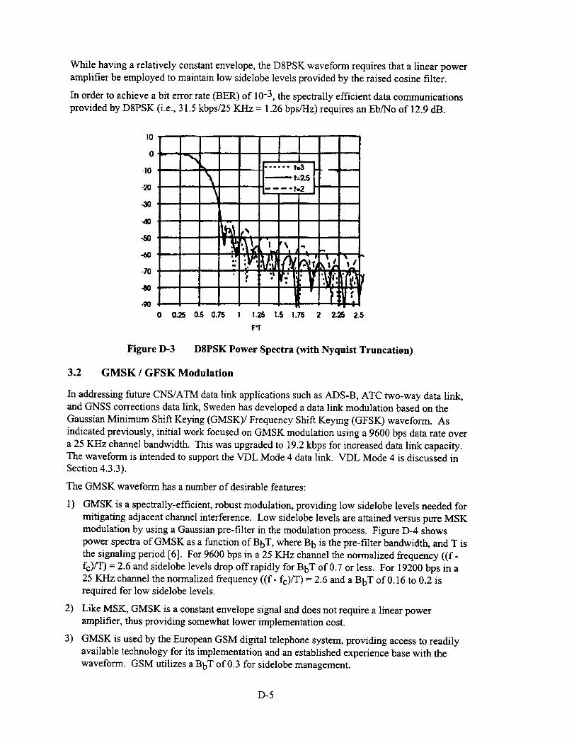
While having a relatively constant envelope, the D8PSK waveform requires that a linear power
amplifier be employed to maintain low sidelobe levels provided by the raised cosine filter.
In order to achieve a bit error rate (BER) of 10 -3, the spectrally efficient data communications
provided by D8PSK (i.e., 31.5 kbps/25 KHz = 1.26 bps/Hz) requires an Eb/No of 12.9 dB.
lO
0
-lo
-20
-40
-50
-60
-70
--8o
-90
\
o 0.25 0.5 0.75
..... t.3,,iI
.... t,.2
q% v
,
1.25
F'T
1.,5 1.75 2 2.25 2.5
Figure D-3 D8PSK Power Spectra (with Nyquist Truncation)
3.2 GMSK / GFSK Modulation
In addressing future CNS/ATM data link applications such as ADS-B, ATC two-way data link,
and GNSS corrections data link, Sweden has developed a data link modulation based on the
Gaussian Minimum Shift Keying (GMSK)/Frequency Shift Keying (GFSK) waveform. As
indicated previously, initial work focused on GMSK modulation using a 9600 bps data rate over
a 25 KHz channel bandwidth. This was upgraded to 19.2 kbps for increased data link capacity.
The waveform is intended to support the VDL Mode 4 data link. VDL Mode 4 is discussed in
Section 4.3.3).
The GMSK waveform has a number of desirable features:
1) GMSK is a spectrally-efficient, robust modulation, providing low sidelobe levels needed for
mitigating adjacent channel interference. Low sidelobe levels are attained versus pure MSK
modulation by using a Gaussian pre-filter in the modulation process. Figure D-4 shows
power spectra of GMSK as a function of BbT, where B b is the pre-filter bandwidth, and T is
the signaling period [6]. For 9600 bps in a 25 KHz channel the normalized frequency ((f-
fc)/T) = 2.6 and sidelobe levels drop offrapidly for BbT of 0.7 or tess. For 19200 bps in a
25 KHz channel the normalized frequency ((f- fc)/T) = 2.6 and a BbT of 0.16 to 0.2 is
required for low sidelobe levels.
2) Like MSK, GMSK is a constant envelope signal and does not require a linear power
amplifier, thus providing somewhat lower implementation cost.
3) GMSK is used by the European GSM digital telephone system, providing access to readily
available technology for its implementation and an established experience base with the
waveform. GSM utilizes a BbT of 0.3 for sidelobe management.
D-5

Bbt•- (.sK) i
k..................._ ..............L.........1.o.-........................_.......................-20 . 0.7 i
0.5.
i ozs.- i -
-80 i O. 3 ! ..........
i o.Z
-I00
-1200 0.5 1.0 1.5 2.0 2.5
NORMALIZED FREQUENCY _ (f-fc}T
Figure D-4 Power Spectra of GMSK
GMSK is a robust, spectrally efficient modulation that was selected for GSM. GMSK is also a
very interesting waveform since it can be viewed from a :aumber of perspectives:
1) GMSK can be viewed as a member of the m-ary PSK modulation waveforms with m=4.Demodulation is either coherent or differentially coherent (if data is encoded differentially).
2) GMSK can also be viewed as m-ary FSK modulatior_ with m=2 (thus the reference asGMSK/GFSK). FSK can be detected either coherenlty or non-coherently.
The actual implementation approach followed by GMSK rGFSK is significant since it effects the
Eb/No needed to achieve a specific bit error rate (BER). For a BER of 10"3, the following
Eb/N o ratios are required:
1) Eb/N o = 6.8 dB ifGMSK is demodulated coherently using ideal matched filterdetection.
2) Eb/No = 9.8 dB is needed if the waveform is demodulated as coherent GFSK.
3) Eb/N o = - 9.3 dB is needed if the waveform is d_modulated as differential-coherentGMSK, where the data is differentially encoded ;_rior to transmission.
The above Eb/No ratios are computed for ideal signal de:ection and represent the best attainable
performance. Clearly, the selected demodulation approa :h greatly effects the achievable Eb/No.
An additional consideration in determining Eb/No for GMSK is the effect of the Gaussian pre-
filter. While ideal MSK (BbT = oo, i.e., no pre-filter) achieves the Eb/N o computed above, the
effect of any prefiltering begins to degrade the Eb/No. Figure D-5 shows the adjacent channel
interference of GMSK as a function of BbT [6]. In ordel to achieve -60 dB of rejection for
25KHz channel spacings (fs/T = 25KHz/19.2 kbps = 1.31_,BbT must be between 0.16 and 0.2.
This represents significant bandlimiting of the signal in order to fit the 19.2 kbps data rate intothe 25 KHz channel. As shown in Figure D-6, the degradation to Eb/N o for GMSK as a function
of BbT requires an additional 1 to 2 dB of Eb/No [6].
D-6

Toavoid excessive intersymbol interference for low BbT (0.12 to 0.2), the 19.2 kbps GMSK
waveform was modified to use a BbT = 0.3 and used a lower modulation index to provide the
necessary bandlimiting (i.e., the GMSK modulation index, h = 0.5 was reduced to h = 0.25). The
waveform can no longer be considered GMSK and is instead GFSK.
v
w
w
°1
-20
-4O
-6O
-80
-100
BbT = _ (MSK)
/ 0.7
0.5
-1200
Figure D-5
0.5 1.0 1.5 2.0 2.5
NORMALIZED CHANNEL SEPARATION : fsT
Adjacent Channel Interference of GMSK
2
Figure D-6
0 0.2 0.4 0.6 0.8
LPF BANDWIOTH : BIT
Theoretical Eb/No Degradation of GMSK
D-7

3.3 Comparison of D8PSK (31.5 kbps) and GMSK/GFSK (19.2 kbps)
(in Terms of Eb/N,, S/N and D/U)
With the above background information on the two modulation candidates, this section provides
a relative performance comparison of D8PSK and GMSK/GFSK. Table D-1 summarizes the
Eb/No, S/N and D/U performance of these waveforms. A BER of 10 -3 is assumed.
Bit Error Rate = 1 E-3
Waveform Eb/N o 1 S/N = (Eb/No) * R/W D/U 32
D8PSK at 31.5 kbps 12.9 dB 17.7 dB 23 dB
(12.9 + 4.8) (16 dB + 7 dB fade margin)
GMSK/GFSK at
19.2 kbps
7.8 to 8.8 dB 10.8 to 11.8 dB 14 dB
- as coherent PSK (6.8 dB + 1 to 2 (7.8/8.8 + 3) (7 dB + 7 dB fade margin)
dB due to BbT )
10.8 to 11.8 dB 13.8 to 14.8 dB 14 dB
- as coherent FSK (9.8 dB + 1 to 2 (10.8/11.8+3) (7 dB + 7 dB fade margin)
dB due to BbT )
10.3 to 11.3 dB 13.3 to 14.3 dB 14dB- as differentially
coherent PSK (9.3 dB + 1 to 2 (10.3/11.3 + 3) (7 dB + 7 dB fade margin)
dB due to BbT )
Table D-1 Comparison of D8PSK and GMSK/GFSK in Terms of Eb/No, S/N and D/U
1 Data link system performance is typically compared in terms of Eb/No. While GMSK/GFSK
demodulated as coherent PSK has an advantage in te_ns of Eb/No, this demodulation
approach is not as robust as GMSK/GFSK using coh.'rent FSK or differential PSK. Coherent
PSK demodulation requires accurate phase tracking _nd likely will require lengthy training
and synchronization sequences to achieve phase cohc_rence. Coherent PSK is also more
vulnerable to channel impairments and self-interfere:ace (D/U) during initial signal
acquisition. The more likely method for GMSK/GFSK demodulation is either as coherent
FSK or differentially coherent PSK. When compared to D8PSK, the performance difference
between GMSK/GFSK for coherent FSK or differenzially coherent PSK demodulation is 1 to
2.5 dB. This 1 to 2.5 dB is the price paid for the higher channel data rate for DSPSK.
Signal to Noise ratios (S/N) are computed using the appropriate R/W ratios for each waveform.
For D8PSK, R = 31.5 kbps and W = 10.5 K/-Iz as the matched filter detection bandwidth. For
GMSK/GFSK, R = 19.2 kbps and W = 9.6 KHz as tie matched filter detection bandwidth.
Typically, the S/N ratio is not used for one-on-one comparison of modulation waveforms
since it includes the data rate, R, and thus no longer i3rovides an apples-to-apples
comparison. The S/N ratio is important in terms of determining that a sufficient amount of
signal power is available to achieve the desired sign_l rate.
D/U represents the 'Desired versus Undesired' signal ratio that can be tolerated in meeting the
specified BER. It is an important parameter of the I",_bustness of a waveform to self-interference
and affects frequency reuse. From Table D-l, D8PSK is clearly not as robust as GMSK/GFSK
when it comes to D/U. The impact of D/u on frequency reuse is discussed in Section 3.5.
D-8

BasedontheassumptionthatGMSK/GFSKwill usedemodulationotherthancoherent PSK
demodulation, Table D-lindicates that there is only a 1 to 2.5 dB difference between the D8PSK and
GMSK/GFSK waveforms in terms of Eb/N o. There is a considerable difference between D/U for
D8PSK versus GMSK/GFSK with GMSK being more robust. This is the unavoidable price of tryingto achieve a higher data rate using DSPSK.
3.4 GMSK Demodulation Performance
To gain a better understanding of GMSK/GFSK performance beyond the theoretical results just
stated, several demodulation approaches were evaluated based on published papers. Figures D-
7, D-8 and D-9 show typical demodulators for coherent orthogonal detection, differentiallycoherent detection, and non-coherent limiter discriminator detection of GMSK.
Figure D-7 Coherent orthogonal GMSK detection
_Lowpass Fiite_-_ FM
[(bandwidth Bi] - [M°dulat°r[
Figure D-8 Differentially coherent GMSK detection
dNatP_Za[Gaussian I I 17x__ I Limiter ' 7 I .. /
|(bandwidth B1 IM°du'at°r|
Figure D-9 Noncoherent limiter discriminator GMSK detection
D-9
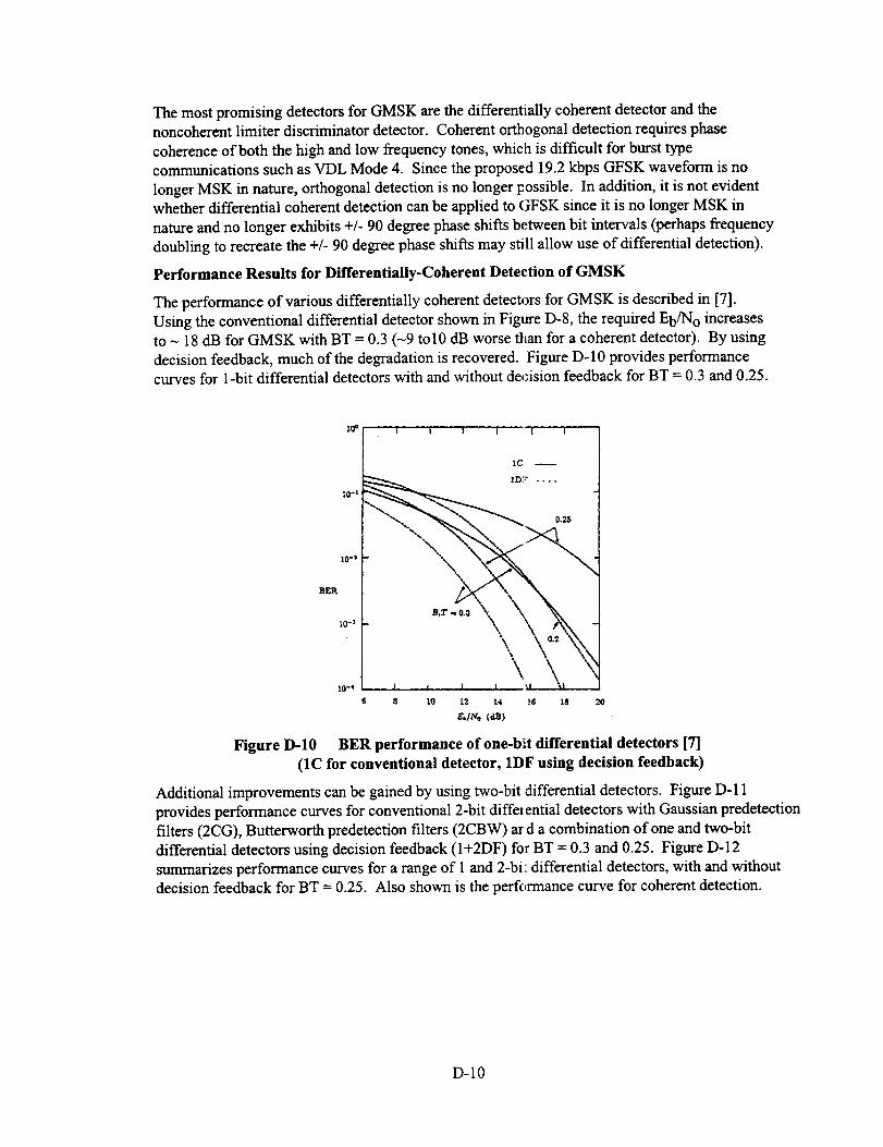
The most promising detectors for GMSK are the differentially coherent detector and thenoncoherent limiter discriminator detector. Coherent orthogonal detection requires phase
coherence of both the high and low frequency tones, which is difficult for burst type
communications such as VDL Mode 4. Since the proposed 19.2 kbps GFSK waveform is no
longer MSK in nature, orthogonal detection is no longer possible. In addition, it is not evidentwhether differential coherent detection can be applied to GFSK since it is no longer MSK in
nature and no longer exhibits +/- 90 degree phase shifts between bit intervals (perhaps frequency
doubling to recreate the +/- 90 degree phase shifts may still allow use of differential detection).
Performance ResuRs for Differentially-Coherent Detection of GMSK
The performance of various differentially coherent detectors for GMSK is described in [7].
Using the conventional differential detector shown in Figure D-8, the required Eb/N o increases
to - 18 dB for GMSK with BT = 0.3 (-9 to10 dB worse titan for a coherent detector). By using
decision feedback, much of the degradation is recovered. Figure D-10 provides performance
curves for 1-bit differential detectors with and without decision feedback for BT = 0.3 and 0.25.
lO-t
I I t I [ I
IC --
1D;_ ....
_. 0.25
S_'Rlo-, -\'X___x, N
10-4
8 lO 12 t4 16 18 20
g./t¢o (,m)
Figure D-10 BER performance of one-b_t differential detectors [7]
(1C for conventional detector, 1DF using decision feedback)
Additional improvements can be gained by using two-bit differential detectors. Figure D- 11
provides performance curves for conventional 2-bit differential detectors with Gaussian predetection
filters (2CG), Butterworth predetection filters (2CBW) ard a combination of one and two-bit
differential detectors using decision feedback (I+2DF) for BT = 0.3 and 0.25. Figure D-12
summarizes performance curves for a range of 1 and 2-bi: differential detectors, with and without
decision feedback for BT = 0.25. Also shown is the perff,rmance curve for coherent detection.
D-IO
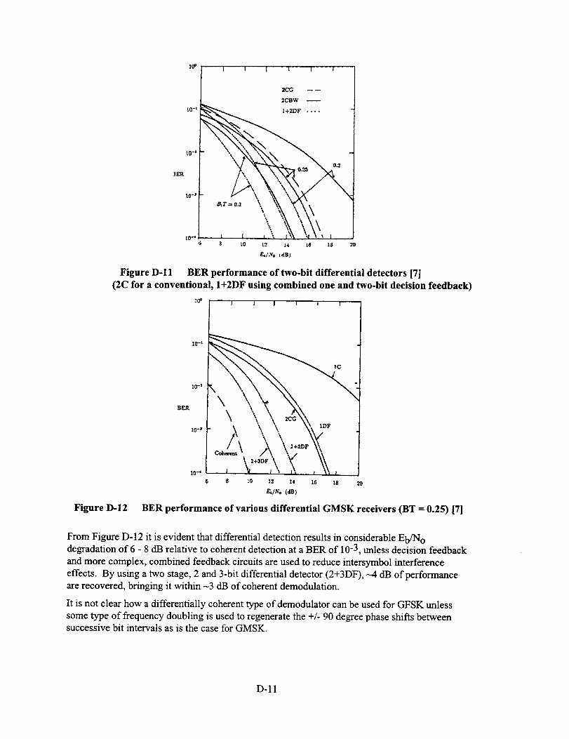
_0° J l I i i i
L0-s
3ER
1.0-_
2CG -- --
2CBW --
I+2DF ....
,.T:.._ \ '_ -w,_,'., \\ \\',•,..-,,x,\\\, , ,\ \5,,
$ LO L2 L4 ZB lS
F_/.vo (riB)
."0
Figure D- 12
Figure D-11 BER performance of two-bit differential detectors [7]
(2C for a conventional, I+2DF using combined one and two-bit decision feedback)
I J I i I I I
IO-R10-2
1O -_
I0-_ t
s s zo z2 z4 z6 _s 2o
_/N, (dB)
BER performance of various differential GMSK receivers tBT = 0.25) 171
From Figure D-12 it is evident that differential detection results in considerable Eb/N odegradation of 6 - 8 dB relative to coherent detection at a BER of 10"3, unless decision feedback
and more complex, combined feedback circuits are used to reduce intersymbol interference
effects. By using a two stage, 2 and 3-bit differential detector (2+3DF), --4 dB of performance
are recovered, bringing it within -3 dB of coherent demodulation.
It is not clear how a differentially coherent type of demodulator can be used for GFSK unless
some type of frequency doubling is used to regenerate the +/- 90 degree phase shifts betweensuccessive bit intervals as is the case for GMSK.
D-11
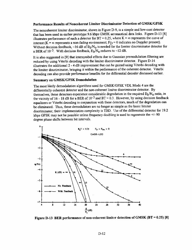
Performance Results of Noncoherent Limiter Discriminator Detection of GMSK/GFSK
The noncoherent limiter discriminator, shown in Figure D-9, is a simple and low-cost detector
that has been used in earlier prototype 9.6 kbps GMSK aeronautical data links. Figure D-13 [8]
illustrates performance of such a detector for BT = 0.25, where K = oorepresents the curve of
interest (K = oorepresents a non-fading environment; FD = 0 indicates no Doppler present).
Without decision feedback, -16 dB of Eb/No is needed for the limiter discriminator detector for
a BER of 10"3. With decision feedback, Eb/N o reduces to -12 dB.
It is also suggested in [9] that intersymbol effects due to Gaussian premodulation filtering are
reduced by using Viterbi decoding with the limiter discriminator detector. Figure D-14
illustrates the additional 2 - 4 dB improvement that can be gained using Viterbi decoding with
the limiter discriminator, bringing it within the performance of the coherent detector. Viterbi
decoding can also provide performance benefits for the differential decoder discussed earlier.
Summary on GMSK/GFSK Demodulation
The most likely demodulation algorithms used for GMSK/GFSK VDL Mode 4 are the
differentially coherent detector and the non-coherent limiter discriminator detector. By
themselves, these detectors experience considerable degradation in the required Eb/N o ratio, in
the vicinity of 16 - 18 dB for a BER of 10 -3 and BT = 0.3. However, by using decision feedback
equalizers or Viterbi decoding in conjunction with these detectors, much of the degradation can
be eliminated. Thus, these demodulators are no longer as simple as the basic limiter
discriminator; their implementation complexity is TBD. Use of the differential detector for 19.2
kbps GFSK may not be possible unless frequency doubling is used to regenerate the +/- 90
degree phase shifts between bit intervals.
Figure D-13
BIT = 0.25 FO = FOnt = 0
GMSK-LDD
K (dB) =
No Feedback
With Feedback
12 16 20 24 28 32 36 40
BER performance of non-coherent limiter detection of GMSK (BT -- 0.25) [81
D-12

Figure D-14
°• "'X-...j(.,.
-I "z._.._.x"_" " _'_:':_:"Z,_.
• _._<-2_ _r" "_" "_--_ ._ _.....
_'_ "_cQ, _ _-,, _',, "_..
- ,,"":..., "_.
•. ',
0 2 4 6 8 10 12 14 16
Eb/N0,dB
Limiter discriminator detection (LDD) with V'D, L' -- 1 Gaussian
approx.......... LDD with VD, L' = 2 Gaussian approx•
............. LDD with decision feedback (FB), Gaussian approx.
....... x ...... LDD with FB, actual
............... Coherent optimal receiver
o LDD with VD, L' = l, simulated
• LDD with VD, L' -- 2, simulated
BER performance of non-coherent limiter detection of GMSK (BT = 0.25)
with decision feedback (FB) and/or Viterbi decoding (VD) [9]
Throughout all of this discussion, it is not clear what the effect ofBT = 0.3 and using amodulation index of h = 0.25 has on the D/U performance of 19.2 kbps GFSK. Additional
simulation analysis is required to determine expected D/U performance for these detectors.
3.5 VHF Frequency Engineering for VHF Aeronautical Data Link
This section examines the frequency reuse distance as it relates to VHF aeronautical data link.
Co-channel DFLT
Figure D-15 illustrates the cylindrical coverage models that are typically used in determining the
frequency reuse distance for co-channel D/U ratios. Figure D-15a illustrates the model for two-
way data link, while Figure D- 15b illustrates the model for ground broadcast stations. In both
cases, an aircraft is shown at the edge of the coverage volume at a range of dD and is subjected
to unintended co-channel interference by another aircraft in the case of Figure D-15a, or another
ground station in the case of Figure D-15b. In either case, this unintended distance is dU. The
D/U (dB) ratio is related to range as 20 log (dU / dD). Assuming that radio line of sight (RLOS)
is not encountered first, the facility separation distance for frequency reuse is thus the sum of the
distances as follows: 1) for two-way data link facilities this distance is equal to _ dD(A) + dU
(own aircraft to interfering aircraft) + dD(B)-, and 2) for ground broadcast facilities the reusedistance - dD + dU. If this distance exceeds RLOS, then the interference distance, dU becomes
equal to R_LOS.
D-13
Airborne
Altitude stance dD_a)
Ground Station A
Coverage Volume
facility separation distance =
dD(A)+ dU + do(B)Ground Station B
Coverage Volume
Figure D-15a Facility Separation for Two-Way Data Link Communications
Airborne
Userundesired
.... distance du
distance d D
Facility separation
distance = d o + d UGround Station A Ground Station B
Coverage Volume Coverage Volume
Figure D-15b Facility Separation for Ground Broadcast Data Link Communications
Table D-2 summarizes the frequency reuse distance calculation for a number of aeronautical data
link services as a function of D/U. The service radii of both ground facilities are assumed to be
equal. D/U ratios of 14 dB and 20 dB are currently used in making frequency reuse assignmentsfor conventional aeronautical VHF voice communications in the USA and by ICAO,
respectively. Previously, D/Us used for D8PSK were 23 cB (16 dB+ 7 dB margin) and for
GFSK 14 dB (7 dB+ 7 dB margin). The 7 dB margin repJ esents additional allocation to D/U,
beyond what is provided by the actual modulation wavefo:m. This margin includes fading
effects, any imbalances in transmitter gains, transmit and i eceive antenna gains, etc.. As will be
seen, the actual margin used can greatly effect the frequency reuse distance.
Table D-2 uses 14, 18,20 and 23 dB to calculate the expected frequency separation needed in
making frequency reuse calculations.
Note 1: Radio line of sight (RLOS) calculations are based on 4/3 earth radius radio coverage.For two elevated sites the RLOS (nmi) = 1.23 (scrt (hl) + sqrt (h2)). A 100 ft antenna
height is assumed for ground broadcast stations. For two-way data link, hl and h2 are
the heights associated with the two aircraft, e.g., ial = h2 = 45,000 ft for high altitudeenroute areas, and RLOS is -522 nmi.
D-14

Note2: Frequencyreusedistanceiscomputedasfollows(refertoFigureD-15):
a) Two-waydatalinkreusedistance= dD(A)+ min(10(D/U)/20* dD(A),RLOS)+dD(B),forgroundstationsA andB.
b) Groundbroadcaststationsreusedistance= dD + min(10(D/U)/20* dD,RLOS)
In TableD-2,thecolumnsof interestareD/U= 14 dB and D/U = 23 dB, which represent GFSK
and D8PSK, respectively. The frequency reuse distance can be used to compute data link
capacity as bits-per-second per unit area (bps/nmi 2. Table D-3 lists the data link capacities for
the various VHF aeronautical data link applications.
From Table D-2, it is observed that low D/U ratios provide frequency reuse advantages for data
link applications with relatively high altitude but relatively short range coverage regions due tothe relatively large RLOS, e.g., terminal area Local Controller communications (refer to Tables
D-2 and D-3). Conversely, there is no benefit of having low D/U ratios (at least D/Us of 14 dB)
for 1) long range communications regions, since RLOS becomes the limiting interference range,
and for 2) relatively low altitude coverage regions with moderate communications ranges, which
provide low RLOS. High altitude (45,000 ft) enroute two-way data link (Table D-2) is an
example where RLOS limits the interference region for all D/Us greater than 14 dB.
Clearly, the D/U margin that is required to ensure high-integrity data link performance (in
addition to the D/U associated with the modulation waveform) has a significant effect on
whether any frequency reuse benefits can be gained. With the exception of terminal area Local
Controller two-way data link, most other aeronautical VHF data link applications show little orno frequency reuse advantage for D/Us > 18 dB.
Adjacent Channel Performance
The first adjacent channel is the most difficult off-channel interference requirement for both D8PSK
and GFSK modulations. Typical VHF Comm receivers are capable of attenuating adjacent channel
signals by -60 dB. This level of performance is also expected for D8PSK and GFSK data link
receivers. The 60 dB adjacent channel attenuation is allocated to D/U, with the remainder being
available for "near-far" protection. Typical VHF Comm receivers use a D/U of 14 dB, thus leaving 46
dB of"near-far" protection. For a 150 rimi service volume (i.e., "far" transmitter) the interferingtransmitter (i.e., "near" transmitter) can be as close as 0.75 nmi from the receiver. Thus for VHF Comm
the adjacent channel interferer (usually another airbome aircraft) can be very close to the receiver
without causing any degradation. Thus VHF Comm service volumes on adjacent channels can be
assigned to reach within 0.75 nmi (see Figure D-16). This greatly facilitates frequency reassignment.
0.75 nm i
Figure D-16
Ground Station A Ground Station B
Coverage Volume Coverage Volume
(f= x M Hz) f= (x + .025) M Hz
Adjacent channel coverage region assignment (two-way data link)
D-15

E
cJ_
¢..)
c_
L_
0o
*
(._
-x*
*
.q-
o
q-
-3(-
(._
-X*
o
(-_
-X- -X- -)[- *X-
* _ -x*
c_¢.)
c_o
c_
s.,
o,m
o
m
o
c_
os...
c_
s...
2
o
o._
g _
°._.._
• _
D-16
Facility Type
Enroute two-waydata link
(45,000 ft altitude)
Enroute two-waydata link
(25,000 ft altitude)
Terminal area
Local Controller
(25,000 fl altitude)
NABS-V
(20,000 fl altitude)20 nmi service radius
NABS-V
(20,000 fl altitude)30 nmi service radius
Weather
(AWOS/ASOS)
(10,000 fl altitude)
Departure ATIS
(100')
GFSK
Frequency ReuseDistance
(D/U = 14 dB)
822
420
210
120
180
150
35
D8PSK
Frequency ReuseDistance
(D/U _>23 dB)
822
509
449
206
216
160
35
Relative Data Link
Capacity (bps/nmi 2)
D8PSK/GFSK
1.64
(e.g., 31500/19200)
1.12
0.36
0.56
1.14
1.44
1.64
Table 1)-3 Relative Data Link Capacities of D8PSK versus GFSK for Various Data Link Applications
D-17

4. Description of VHF Data Link Modes
This section provides an overview of each of the VHF da:a link modes currently being developed
for future CNS/ATM data link applications. The expecteJ benefits and potential shortcomings of
each approach are identified.
VDL Modes 2 and 3 have been under development in RTCA SC-172 and the ICAO AMCP for
ATC/ATS data link applications for about 4 years. VDL Mode 4 is receiving more recent
consideration for ADS-B and is also capable of providing ATC/ATS services.
4.1 VDL Mode 2
VDL Mode 2 is intended to serve as an air-ground data link and is capable of both two-way,
addressed communications and can also provide broadcast services. VDL Mode 2 sub-network
layers are described below.
4.1.1 Physical Layer
The VDL Mode 2 physical layer uses 31.5 kbps D8PSK rlodulation using raised cosine filtering
(a = 0.6) for spectral shaping to maintain the signal withia the 25 KHz channel, with low
sidelobes on the adjacent channel. The VDL Mode 2 RF pulse consists of the following:
1) Transmitter power stabilization sequence - this interval allows the transmitter to ramp up its
RF power and to provide a stable signal to allow the receiver to establish an Automatic Gain
Control Setting (AGC) in preparation for acquiring message synchronization. The
transmission sequence consists of four '000' symbols
2) Synchronization and ambiguity sequence - a 16 symbol (48 bits) unique word
synchronization sequence is used to acquire precise message synchronization to allow datademodulation.
3) Message header - the header consists of a 17-bit message length word and 3 reserved bits,
yielding 20-bits of header. The 17-bit message length word indicates the number of data bits
that follow the header. A (25,20) block code for error correction yields an additional 5 bits
of coding. The 25-bit header is appended with 2-bits :.o yield a nine symbol header.
4) Data sequence - the maximum length data message that can be transmitted in a single RF
pulse is 255-bytes. The data sequence uses a Reed Solomon RS(255,249) 28-ary forwarderror correction code to ensure a 10-4 bit-error-rate. Thus a maximum of 1992 bits of data
can be sent in a single VDL Mode 2 transmission. Fc r shorter messages, the RS code can be
reduced, i.e., fewer parity symbols are used. Interleaving of data bytes is used to improve
the performance of the RS code. Prior to transmission, the bit stream is bit-scrambled using
a pseudo noise (PF0 code to aid clock recovery at the receiver and to provide a random data
sequence to create a more uniform signal spectrum.
The physical layer performs channel sensing to determine if the channel is available for signaltransmission. In addition, receive-to-transmit and transm t-to-receive turnaround time is critical
and is maintained to a minimum to support the Carrier Sease Multiple Access (CSMA) protocolused in the data link layer.
D-18

4.1.2 Data Link Layer (MAC sublayer)
The media access channel (MAC) sublayer provides transparent channel access to the DLS
sublayer. The VDL Mode 2 MAC layer uses non-adaptive p-persistent CSMA to allow equitable
access opportunity to all stations. The MAC sublayer also provides an indication of channel
congestion to the management entity, which determines the quality-of-service of the link. The
MAC layer uses a number of timers, the persistence parameter (p) and retry counter to performCSMA and to compute channel congestion.
4.1.3 Data Link Layer (DLS sublayer)
The data link services (DLS) sublayer implements the Aviation VHF Link Control (AVLC),
which is a modified version of the High Level Data Link Control (H:DLC) protocol (ISO 3309).
The DLS processes data link frames and transfers received and transmit data to / from the ISO-
8208 sub-network layer. The AVLC frame format is shown in Figure D-17.
From Figure D-17 an AVLC frame begins and ends with a '01111110' flag that provides thedemarcation between frames. Contained within the frame are the destination and source
addresses that indicate the participant DLS entities. Following the addresses is a link control
field that implements the AVLC frame message exchange and protocols. The control field is
followed by the information field, which represents the user data. The frame ends with a 16-bit
frame check sequence that is used to detect frame errors.
AV-LC DLS services consist of frame sequencing, error detection, station identification,
broadcast addressing and data transfer. The DLS determines if a frame is addressed to it, detects
whether or not the frame was received correctly, and ensures that no redundant frames are
transferred to the sub-network layer.
DESCRIPTION OCTET NO 8 I 7 ]FLAG - 0 I
1 22 L 23 I
-- Destination J --T--2 15
-- Address "1-- --T'-3 8
-- Fietd --T-- "T-4 1
5 - 22 i
-- Source i "-I-"6 15
- Address --1-- "-W"7 8
- Field "1-- --T"8 1
Link Control Fietd 9 I I
I NFORMAT ION N- 2 I I
FRA.NE N-I 9 i i- CHECK - -
SEQUENCE N
FLAG o
BIT NUMBER
first bit
transmiited
°1 '1 'l 31 2I I 1 1 I 0
24 [na 25 ' 26 ' 27 JA/G', ODest tion I 21 0
DL S-'_ress__ --I-- "-1-" -7-- 14 0
-1-- -'I-" "-I-" --I--7 O
Z4 I 2S' 26, ' 27 I C/R OSource _ i 21 O
Dk_'t-_ddress-T- "-I-- --r- 14 O
--I-- --r- "-r- --r_7 I
i i )
P/F I1 iUS :R DATA
I_t SICdlIF|_UIT OCTI_T
! I
i i 16
1 -"- "- Li r sxG.Y r -r- --r- S0 1 1 1 1 1 1 0
Figure D-17 AVLC Frame Format [10]
D-19
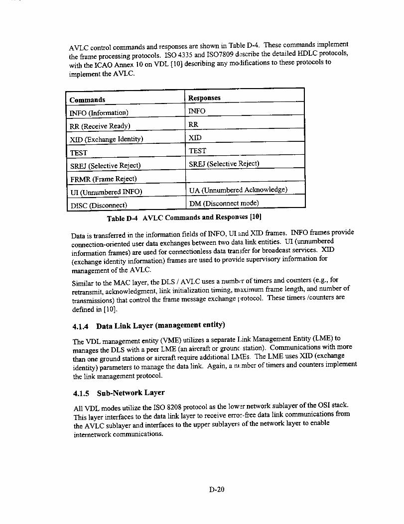
AVLCcontrolcommandsandresponsesareshowninTableD-4. Thesecommandsimplementtheframeprocessingprotocols.ISO4335andISO7809describethedetailedHDLCprotocols,withtheICAOAnnex 10 on VDL [10] describing any modifications to these protocols to
implement the AVLC.
Commands Responses
INTO (Information) INFO
RR (Receive Ready) RR
XID (Exchange Identity) XID
TEST TEST
SREJ (Selective Reject) SREJ (Selective Reject)
FRMR (Frame Reject)
UI (Unnumbered INFO) UA (Unnumbered Acknowledge)
DISC (Disconnect) DM (Disconnect mode)
Table D-4 AVLC Commands and Responses [10]
Data is transferred in the information fields of INFO, UI and XID frames. INFO frames provide
connection-oriented user data exchanges between two data link entities. UI (unnumbered
information frames) are used for connectionless data transfer for broadcast services. XID
(exchange identity information) frames are used to provide supervisory information for
management of the AVLC.
Similar to the MAC layer, the DLS / AVLC uses a numb¢:r of timers and counters (e.g., for
retransmit, acknowledgment, link initialization timing, maximum frame length, and number of
transmissions) that control the frame message exchange t_rotocol. These timers/counters are
defined in [10].
4.1.4 Data Link Layer (management entity)
The VDL management entity (VME) utilizes a separate lank Management Entity (LME) to
manages the DLS with a peer LME (an aircraft or grounci station). Communications with more
than one ground stations or aircraft require additional LMEs. The LME uses XID (exchange
identity) parameters to manage the data link. Again, a m_mber of timers and counters implement
the link management protocol.
4.1.5 Sub-Network Layer
All VDL modes utilize the ISO 8208 protocol as the lower network sublayer of the OSI stack.
This layer interfaces to the data link layer to receive error-free data link communications from
the AVLC sublayer and interfaces to the upper sublayers of the network layer to enableinternetwork communications.
D-20

4.1.6 Summary of VDL Mode 2
VDL Mode 2 is a data-only data link (i.e., no digital voice capability) that provides an order of
magnitude increase in channel capacity versus VDL Mode 1. The increase in capacity is the
direct result of the 31.5 kbps D8PSK waveform (versus the 2400 bps MSK waveform used by
VDL Mode 1). As indicated in Section 3, D8PSK requires a D/U of 16 to 20 dB which
influences frequency reuse. Like VDL Mode 1, VDL Mode 2 uses CSMA channel access
protocol. In addition, VDL Mode 2 uses the bit-oriented protocol (versus character-oriented
protocol of ACARS) that provides compatibility to the ATN.
VDL Mode 2 is the simplest of the high-rate VDL modes being developed and is well suited
when channel efficiency and access demands are not at a premium. The CSMA protocol limits
VDL Mode 2 to providing strategic data link communications and cannot be used for time-
critical, tactical communications. VDL Mode 2 is intended for addressed, air-ground
communications, and can also provide a broadcast data link capability for high-rate broadcast
applications, e.g., weather information, including precipitation maps, etc..
In order to achieve a simplex broadcast data link using VDL Mode 2 will require additional
standardization activity to allow the AVLC data link sublayer to be bypassed, eliminating the
need for message ACKs (Acknowledgements) that are currently required to maintain a link
connection. Table D-5 summarizes the performance of VDL Mode 2. VDL Mode 2 is defined
in detail in the ICAO Annex 10 [10] and the associated ISO standards.
Communications Performance
Throughput delay moderate (_ 10 sec), depends on channel
loading
Message integrity, priority yes
ATN Compatibility yes
VHF Specific Services (VSS), i.e., non-ATN not currently planned but possible
Broadcast Capability well suited for efficient high-rate broadcast link
(additional standardization work required)
Voice/Data Data only
D8PSK D/U of 16/20 dB for frequency reuse
Table D-5 VDL Mode 2 Communications Performance Summary
D-21

4.2 VDL Mode 3
Mitre, under the sponsorship of the FAA, has developed t_ e VDL Mode 3 concept as the next
generation VI-IF communications system, also called NEXCOM. VDL Mode 3 provides a flexiblearchitecture that allows a range of system configurations fi)r voice, data and integrated VI-IF digital
voice and data link simultaneously for multiple users on one channel resource. VDL Mode 3 was
designed, in part, to address the VHF frequency congestion problem by providing digital voice anddata link services with efficient use of available VI-IF Comm frequency resources. VDL Mode 3
MASPS and SARPS are currently being developed by RTCA SC-172 and the ICAO AMCP. This
section provides an overview of VDL Mode 3 and examines its communications performance.
Unlike VDL Mode 2, which provides data link services using CSMA, VDL Mode 3, using
TDMA channel access, is capable of providing a range of communications capabilities. TheVDL Mode 3 communications modes are 4V, 3V1D, 2V2D and 3T for standard range
communications and 3V, 3S, 2V1D and 3U modes when extended communications range is
desired. The 4V mode indicates that the VDL channel is configured to provide 4 independent,
dedicated digital voice sub-channels within the 25 KHz VHF Comm channel. This is
accomplished using different time slots for each voice sub-channels. For the 3V1D mode, one ofthe four voice channels is used to provide a shared data channel (1D). The 2V2D mode provides
two voice and data sub-channels. Each voice channel is paired with a dedicated data channel to
allow, for example, two separate ATC controllers providing dedicated voice and data services forvoice and CPDLC data link simultaneously on one channel The 3T mode is intended to provide
demand assigned voice and data services.
Extended range modes have fewer time slots available to them due to additional range guard time
requirements and are thus constraint to providing 3V sub-channels. The 3S mode allows adedicated voice channel to be sent via 3 ground stations, intended for providing site diversity.
2V1D is similar to 3VID but is intended for extended range communications. The 3U mode allows
voice sub-channels that are not managed by the ground station, i.e., they are unprotected (U).
4.2.1 Physical Layer
Similar to VDL Mode 2, VDL Mode 3 RF pulses use 31.5 kbps D8PSK modulation using raised
cosine filtering (_x= 0.6) to maintain the signal within the 25 KHz channel and provide lowsidelobes on the adjacent channel. The typical RF pulse is also similar to VDL Mode 2.
However, since VDL Mode 3 is a TDMA system and has a number of different modes, RF
pulses are assigned within time slots in several ways. Figltre D-18 shows a typical time slot and
the associated RF pulse transmissions for both airborne and ground transmissions.
Unlike VDL Mode 2, where one basic RF pulse is transmi_ed using CSMA, VDL Mode 3 uses
two RF pulses within a single time slot, a management (M) burst, and a voice/data (V/D) burst.Each of these bursts has the typical ramp-up (5 symbol times) and ramp-down (2 symbol times)
intervals, 16-symbol synchronization sequences, system data for the M burst, and a header anduser information in the V/D burst.
Special synchronization sequences are used to allow successful synchronization, yet distinguishbetween the different types of requests and responses that are indicated by the transmission.
Synchronization sequences are as follows:
Standard synch S 1 (for M burst downlink)
Net entry requests S 1* (for M burst downlink)
Poll responses $2. (for M burst up/downlink)
V/D burst synch S2 (for V/D burst)
D-22

30 ms slot st 31.5 kbps (10.5 K symbol/sac)
S" is iS _S is e
S ''A.,ncl, aA. cl!lI \0
ViID Subchannel Burst
192
User Information
Airborne Transmissions
Propa_o.
30m
M Subchannel Burst
5' 16 32 5 16 8
A-ol-k A'lil
V/D Sube.hannel Burst
192
Userlnfornmtlon
Ground Transmissions
Propagation
30m
Figure D-18 VDL Mode 3 Burst Transmissions - TDMA Timing Budget [11]
The M burstcontainssystemdata,consistingofmessage ID, slotID, groundstationcode,
channelconfiguration(4V,3VID, etc.),voicesignaland squelchwindow informationand a
rangcofmessage depcndcntdatathatisusedtomaintainchanneland communications
management oftheVDL sub-network.The M-channelburstformatisasfollows:
l) UplinkM-burst
For thenon-3T configuration,32 symbolsarctransmitted,i.e.,96 bits.The 96 bitsconsists
of4 Golay (24,12)codewords. For 3T, systemdataconsistsof 128 symbols,i.c.,384 bits,
consistingof 16 Golay (24,12)codcwords.The Golay countcorrectsup to3 biterrorsor
detcctsasmany asfourbiterrors.
2) Downlink M-Burst
16 symbols,i.c.,48 bits,arctransrnittcd,consistingof2 Golay (24,12)code words.
The V/D burstconsistsofheaderand userinformationdata.The hcadcrconsistsof8 symbols
(or24 bits)and isa singleGolay (24,12)codcword. User informationconsistsof 192 symbols
(or576 bits).Whcn tmnsrnittingdata,theuserinformationisencoded asasingleReed Solomon
RS(72,62)2Lary codc word capablcofcorrcctingup tofivecodeword symbol errors.For voice,
errorcorrectionisincludcdinthevocodcritsclf.The vocoderisexpectedtoprovidesatisfactory
performanceatbit-crror-ratcsof 103. The vocodcrrate(includinginternalerrorcorrection)is
4800 bps (a4000 bps vocoderisused intruncatemode, which occurswhcn systemtiminghas
degradedbelow a specifiedlevel).
Intcrlcavingisnot usedinVDL Modc 3,butbitscramblingisused.
As forVDL Mode 2,thephysicallayershallminimize _ansrnit/receivcturnaroundtirncsto
enhanceperformance.
D-23

4.2.2 Data Link Layer (MAC sublayer)
The MAC sublayer supports both voice and data operations. For data, the MAC sublayer implements
a ground station centralized, reservation-based access to the channel, which permits priority-basedaccess. In addition, the MAC sublayer implements polling and random access methods for
reservation requests. For voice, access is primarily on a "listen before talk" discipline. In order to
avoid a "stuck" microphone, the ground can preempt the airborne user who is occupying the channel.
The MAC protocol timing is as follows: A TDMA frame consists of a 120 ms time interval thatcontains either three or four time slots. The duration of the time slot was selected based on
conventional 4800 bps vocoder frames which are on the order of 20 to 30 ms. For standard range
communications, a TDMA frame consists of four 30 ms time slots with a round trip guard time
of 2.71 ms (Figure D-19). Extended range uses three 40 ms time slots, which were increased in
duration to accommodate the increased guard time. Each time slot contains an M burst for
signalling and link management and a V/D burst for user information.
120n_
IP'"+'IBurst j
000
a) Standard Range
_1_ TDMA frame120 ms
slotC [ slotA ],1
slot A / slot B/
i_, Slot40 ms
I'MI v/oIBur=I Burst
000
b) Extended Range
Figure 1)-19 VDL Mode 3 Frame Structure [12]
User Groups and System Configuration
Using the TDMA frame and time slot structure just described, and the communications modes
indicated previously (4V, 3VID, etc.), a number of user groups and system configurations are
defined for VDL niode 3. These are listed in Table D-6. Up to 4 user groups are possible per
VHF Comm channel. Time slots are identified as slots A, B, C, and D. The system
configuration is determined by the controlling ground station.
D-24
Standard
Range
Extended
Range
System
Conflg.
4V
2V2D
3T
3V
3S
2VID
3U
User GroupsSupponedr
Identifying Time Slots
4/(A, B, C, D)
3/(A. B, C)
2/(A, B)
1 to 3/(B, C, D)
3/(A,B,c)
1/(A)
2/(A,B)
3/(A, B, C)
I
Services to
Each Group
Dedicated voice ckt
Dedicated voice cklw/shared data ckt
Dedicated voice cktw/dedicated data ckt
to Each Group
1
2
2
Demand assigned 1 to 3voice and data
Dedicated voice ckt 1
Dedicated voice cimuit
with 3 station d'wersity
Dedicated voice cktw/shared data ckt
Unprotected voice
3
2
1
Table D-6 VDL Mode 3 System Configurations [12]
Logical Burst Access Channels
Media access is controlled as follows; two TDMA fimnes (120 ms each) are used to define a media
access (MAC) cycle, with individual frames denoted as odd and even. During each MAC cycle,
the VDL grants access using Logical Burst Access Channels (LBACs). LBACs are defined for the
standard configurations (4V, 3V1D, 2V2D, 3V, 2V1D, 3U), the 3T configuration, and the 3S
configuration. The LBACs provide dedicated bursts within the MAC cycle for various types of
communications; e.g., Table D-7 describes the type of channel access det'med for the standard
LBAC configurations. From Table D-7, eight LBACs are available for uplink and downlink
transfers; 1) three M burst downlink LBACs for polling responses, acknowledgements and random
access, 2) two voice and two data LBACs for odd and even frame voice and data transmissions,
and 3) an M burst uplink LBAC that also serves as the M burst that provides the timing reference
point. The timing reference M burst is generated by the ground station to provide the overall
synchronization of the MAC TDMA protocol. In addition to the eight standard LBACs, the 3T
configuration uses 18 LBACs, while the 3S configuration uses 12 LBACs (not shown). LBACs
are precisely timed within the time frames based on the timing reference point.
MAC Timing States
The VDL derives its primary timing from the "timing reference point", which is the time of the
first received symbol of the synchronization sequence of an M burst uplink from the ground
station. If the airborne VDL has not received an updated timing reference, he will eventually fall
out of the primary timing state and will attempt to obtain timing from Voice/Data (V/D) bursts.
The timing state when V/D timing is used is referred to as the Alternate Timing State (ATS). If
timing is further lost, the "free running" timing state is entered. Channel access using Logical
Burst Access Channels (LBACs) is dependent upon the timing state and the management
signalling information obtained from the M uplink burst during the previous MAC cycle.
D-25

I.BAC#*
1
2
3
4
5
A__
air only
air, ground
air only
air. ground
D_crI_on
M downlinkburst usedfor polling response or Random Access (RA)
V/D (voice) burst even frame
M downlinkburstused for ACK or RA
V/D (data) burst even frame
ground only M uplink burst and timingreference point
6 air, ground V/D (voice) bum odd framei
7 air only M downUnkburstused forACK or RA
8 air, ground VK) (data) burst odd frame
Table D-7 Logical Burst Access Channels (LBACs) for Standard Configurations [12]
Voice Access
For voice transmissions, channel access is granted based on the timing state, the voice signalling
information received in the M uplmk burst during the previous MAC cycle, and the system
configuration (4V versus 3T). The 4V, 3VID, 2V2D, 3V and 2V1D modes provide for
dedicated voice access LBACs. The 3T configuration supports voice using reservation
signalling. In the event primary timing degrades sufficimtly, voice communications will be
"truncated", where a reduced rate vocoder algorithm is used to shorten the require V/D burst
transmission (instead of using a 4800 bps vocoder, a red uced rate 4000 bps vocoder is used).
Unprotected voice access (3U) is allowed even in the "free running" timing state.
Link Management & Data Operation Support
The MAC layer at the command of the Link Management Entity (LME) in the Data Link
Services (DLS) sub-layer (Section 4.2.3) uses specific Logical Burst Access Channels (LBACs)
to send messages to support the polling, net entry, and b_aving net message protocols.
In the event the user data is longer than the V/D burst, the MAC layer segments the data into
individual bursts. The end-of message (EOM) flag is se at in the final burst transmission.
Airborne users attain channel access either using "pollirLg" or "random access". When data is
available for downlink, a Reservation Request LBAC is sent to the ground station to indicate that
data is available for downlink. The ground station then sends a Reservation Response LBAC
that signals an "access scheduled" indication along with, information of which slots should be
used in the following MAC cycle. There are no acknowledgment messages required since thoseare handled by the DLS sub-layer AVLC protocol. The protocol also allows for automated
handoff of ground stations for the 3T mode, assuming fl_e radio can be retuned within 2 ms.
4.2.3 Data Link Layer (DLS sublayer)
The DLS sub-layer is functionally identical to the DLS _ublayer of VDL Mode 2 using theAviation VHF Link Control (AVLC) protocol which is a modified version of the ISO 3309
HDLC protocol. The only differences are in the interface to the MAC layer (TDMA for VDL
Mode 3 versus CSMA for VDL Mode 2).
D-26

Theprimarydifferenceis thattheDLSusestheM burstsaspartof itslink management.Beforeanylink canbeestablishedbyaDLSLinkManagementEntity(LME)theVDLmustacquiretwoconsecutiveM uplinkburstscontainingthesameinformationin theinitial 3controlbytes(i.e.,systemconfiguration,squelchwindow,slotID andgroundstationcode).TheM burstsalsoprovidethetimingreference.Oncethenetis initialized,netentryinvolvesthefollowingsequenceof messageexchanges:1)sendingadownlinknetentrymessage,2)receivinganetentryresponsefromthegroundstation,3)sendingan'initialpoll response"downlink,and4)receivingapollingmessagefromthegroundstationthatprovideschannelaccessinformationwhendatacanbedownlinked.
M burstsarealsousedfor"link release"and"handoff"betweengroundstationsand/ or a
Ground Network Interface (GNI). All handoff activity is confined to the lower layers (MAC and
DLS). The sub-network virtual connection is undisturbed. Depending on the time duration
associated with a handoff, an issue of making and breaking connections may arise. While typical
radio communications today use a break-before-make handoff, it may be necessary to perform a
make-before-break handoff (TBD). Make-before-break requires that a new connection is made
before abandoning the previous connection. This may be necessary to avoid loss of important
messages, i.e., a controller instruction via CPDLC. The impact of make-before break may
require an additional channel / sub-channel resource.
As always, a number of timers and counters are used by the DLS to control protocol processing.
4.2.5 Sub-Network Layer
The sub-network layer is the same for all VDL modes and is not discussed here.
4.2.6 Summary of VDL Mode3
Compared to VDL Mode 2, VDL Mode 3 is considerably more complex, providing a wide range
of system configurations for digital voice, data and simultaneous, integrated voice and data
communications via the TDMA time slots (refer to Table D-6 for a list of the system
configurations). VDL Mode 3 was designed to make very efficient use of the 25 KHz channel in
order to increase VHF Comm data link capacity and to help alleviate VHF Comm frequency
congestion. VDL Mode 3 data link communications are ATN-compatible.
Within a single frequency channel VDL Mode 3 is capable of supporting 4 dedicated voice sub-
channels or circuits (4V mode) or can trade off one of the voice circuit as a shared data circuit
(3VID mode). A 2V2D mode allows a dedicated pair of voice circuits to have their own
associated data circuit. The 3T mode allows for demand assigned voice and data. Since VDL
Mode 3 uses discrete addressing in most of its system configurations, this allows for "'caller ID"
and "selective calling" and allows a ground station to pre-empt an airborne voice transmission
due to a stuck microphone condition or voice priority.
Digital voice is accomplished by use of a 4800 bps vocoder. To accommodate four voice
circuits on a 25 KHz channel requires a signalling rate of-31.5 kbps. Thus the VDL Mode 3
requires 31.5 kbps D8PSK modulation to support the intended voice and data capacity. One of
the considerations in using 31.5 kbps D8PSK in a 25 KHz is its sensitivity to co-channel
interference (D/U). VDL Mode 3 has the ability to mitigate some of this interference by using a
coded squelch, which provides time windows around the time of expected signalling bursts. Any
signal detected outside of these times is considered to be interference and is ignored.
D-27

VDLMode3 communicationsaredirectlyundergroundstationcontrol,which provides
centralized timing and reservation-based access among all users, allowing priority-based access.
Airborne users gain access to the channel'using polling and random access for reservation
requests to downlink data.
Sufficient guard times are allocated to the TDMA slots to allow collision free communications
for all line-of-sight scenarios (e.g., 200 nmi range or greater). Guard times must account for
round-trip timing since ground station "timing reference" transmissions experiences a range
delay to distant users, whose own sense of timing is thus delayed. The return trip is to account
for the range delay back to the ground station. The round-trip time is also needed to support
party-line voice for users that are at maximum range, but on opposite sides of the ground station.
With its range of system configurations, VDL Mode 3 is thus ideally suited for providing
ATC/ATS communications of CPDLC, FIS and FIS-B and at the same time provides voice
capability. The end-to-end transfer delay for VDL Mode 3 messaging is expected to be 3
seconds (95% of the time). This relatively low latency (compared to VDL Mode 2) is sufficient
for ATC/ATS communications currently being planned. __'ay new requirements for tactical data
link messaging (latencies on the order of 1 second) may not be accommodated by VDL Mode 3.
Unlike VDL Mode 2, VDL Mode 3 will require more significant changes to protocols to allow
for a broadcast data link mode, e.g., uplink of weather intormation. For broadcast services VDLMode 2 is the better candidate.
The discussion of this section was intended to provide an overview of VDL Mode 3 Much more
detail is available in the VDL Circuit Mode MASPS developed by RTCA SC-172 [ 11], and
Appendix A of the ICAO SP COM/OPS Divisional Meet:ng [ 12], although the later is somewhat
dated. Table D-8 summarizes the performance of VDL Mode 3.
Communications Performance
Throughput delay
Message integrity, priority
low (3 _econds, 95 %)
(may not accommodate tactical
communication)
yes
ATN Compatibility yes
VHF Specific Services (VSS), i.e., non-ATN not currently planned but possible
Broadcast Capability substantial standardization activity required to
provide simplex broadcast mode
Voice/Data Capable of both voice and data
31.5 kbps D8PSK D/U ot 16 to 20 dB for frequency reuse
Table D-8 VDL Mode 3 Communications Performance Summary
D-28
4.3 VDL Mode 4
The VDL Mode 4 concept was developed by Sweden to support future CNS/ATM technology
using a Cellular CNS Concept (CCC). CCC is intended to provide a single CNS system solutionfor all air space users for all phases of flight. Like VDL Mode 3, VDL Mode 4 uses TDMA
access techniques for efficient use of the channel resource, although the two approaches differ.
Unlike VDL Mode 3, VDL Mode 4 is a data-only data link, i.e., it does not support digital voice.
When combined with GPS/GNSS for position and time information, VDL Mode 4 can provide a
wide range of capabilities that are suitable for CNS/ATM data link. VDL Mode 4 supports an
autonomous, self-organizing TDMA (STDMA) protocol that allows a network of aircraft and
vehicles to participate in a communications network without the use of a ground station. VDL
Mode 4 also supports data link networks using passive ground stations used for ADS-B
surveillance, or one or more active ground stations, which direct network communications (i.e.,more centralized control by the ground).
While originally developed more for broadcast applications such as ADS-B and DGPS/DGNSS
data link, VDL Mode 4 also includes capability for addressed point-to-point communications for
a range of applications. VDL Mode 4 is ATN-compatible but also provides VHF Specific
Services (VSS) data link that are non-ATN, which are used for local area, time critical (tactical)communications.
This section provides an overview of VDL Mode 4 from the sub-network perspective (i.e., lowerlayers) and summarizes the key issues associated with using VDL Mode 4 for CNS/ATM data
link. Additional attention is given to the ADS-B application since VDL Mode 4 is being
considered as an alternative to Mode-S for the ADS-B data link (Section 4.3.3.5 discusses VDLMode 4 use for ADS-B).
4.3.1 Physical Layer
Physical layer modulation candidates for VDL Mode 4 are 31.5 kbps DSPSK and 19.2 kbpsGFSK. Both of these waveforms were discussed in detail in Section 3. The D8PSK waveform is
primarily indicated as a candidate due to the legacy of the original VDL Mode 2 and VDL Mode
3 waveform design. However, 19.2 kbps GFSK is the desired waveform for VDL Mode 4 by itsdevelopers. The GFSK waveform requires Gaussian prefiltering using a BT of 0.3 and a
modulation index of 0.25 to maintain the signal within a 25 KHz channel and provide low
sidelobes on the adjacent channel. As indicated in Section 3, GFSK is less sensitive to co-
channel interference (D/U ratio) facilitating frequency reuse for some data link applications and
coverage areas. D/U performance is especially critical for ADS-B, where it is important that
distant aircraft do not interfere excessively with ADS-B reports of close aircraft. As indicated,
GFSK provides a lower channel data rate versus D8PSK in a fixed 25 KHz channel (i.e., 19.2kbps versus 31.5 kbps). This is the direct result of the higher signalling constellation of D8PSK
compared to GFSK, but is also the reason why D8PSK is less robust to D/U. The effective link
capacity is affected by the channel signalling rate, D/U ratio and the intended coverage region(i.e., radio-line-of-sight).
As with VDL Modes 2 and 3, VDL Mode 4 uses a similar RF pulse that consists of transmitter
stabilization and synchronization segments followed by header (optional) and data segments anda transmitter power ramp-down segment. Since VDL Mode 4 intends on all users to have the
same system time (using GPS/GNSS time), the range guard times must only account for one-way
D-29
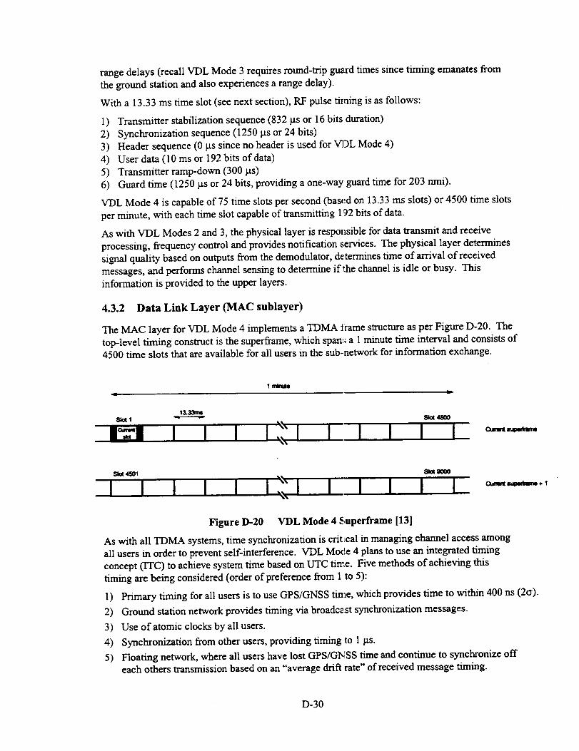
rangedelays(recallVDL Mode 3 requires round-trip guard times since timing emanates from
the ground station and also experiences a range delay).
With a 13.33 ms time slot (see next section), RF pulse timing is as follows:
1) Transmitter stabilization sequence (832 ps or 16 bits duration)
2) Synchronization sequence (1250 _ or 24 bits)
3) Header sequence (0 gs since no header is used for VDL Mode 4)
4) User data (10 ms or 192 bits of data)
5) Transmitter ramp-down (300)_s)
6) Guard time (1250)_s or 24 bits, providing a one-way guard time for 203 nmi).
VDL Mode 4 is capable of 75 time slots per second (based on 13.33 ms slots) or 4500 time slots
per minute, with each time slot capable of txansmitting 192 bits of data.
As with VDL Modes 2 and 3, the physical layer is responsible for data transmit and receive
processing, frequency control and provides notification services. The physical layer determines
signal quality based on outputs from the demodulator, determines time of arrival of received
messages, and performs channel sensing to determine if the channel is idle or busy. This
information is provided to the upper layers.
4.3.2 Data Link Layer (MAC sublayer)
The MAC layer for VDL Mode 4 implements a TDMA _rame structure as per Figure D-20. The
top-level timing construct is the superframe, which span:_ a 1 minute time interval and consists of4500 time slots that are available for all users in the sub-network for information exchange.
I mlnuto
(_Jwt m÷ I
Figure D-20 VDL Mode 4 Superframe [13l
As with all TDMA systems, time synchronization is critLcal in managing channel access among
all users in order to prevent self-interference. VDL Moire 4 plans to use an integrated timing
concept (ITC) to achieve system time based on UTC time. Five methods of achieving this
timing are being considered (order of preference from I to 5):
1) Primary timing for all users is to use GPS/GNSS tin_e, which provides time to within 400 ns (2(_).
2) Ground station network provides timing via broadc2st synchronization messages.
3) Use of atomic clocks by all users.
4) Synchronization from other users, providing timing to 1 _.s.
5) Floating network, where all users have lost GPS/GI_SS time and continue to synchronize offeach others transmission based on an "average drift rate" of received message timing.
D-30
WhileGPS/GNSStimeis themostconvenientandaccuratetimingapproach,thereisconcernthattheindependencebetweentheCNScommunicationsandthenavigationfunctionsiscompromisedby failureofGPS.
TheMAClayerdeterminesslotoccupancybasedontwofactors:1)thereservationtableindicatesthattheslotis reserved,and2) thephysicallayerindicatesthatthechannelisbusy.
TheMAClayershalltransmitin thecurrentslotif 1)areservationhasbeenmadepreviouslyfortheslot,and2) thereisnoreservation,buttheslotisunoccupied.In 2) theMAClayerusesrandomor CSMAaccesstogainchannelaccess.
TheMAC layerisalsoresponsibleforerrordetectionprocessingof theframecyclicredundancycode(CRC).In theeventof anerror,thereceivedburstisdiscarded.If acorrectlyreceivedburstcontainsreservationinformation,theMAClayerforwardsthereservationinformationandthereceivedtimeto theVHFSpecificServices(VSS)sub-layer.Receiveddataandsignalqualityandtransmissionstarttimesof framesarealsopassedto theVSSandDataLink Services(DLS)layers.
4.3.3 VHF Specific Service (VSS) Sublayer
Figure D-21 illustrates the sub-network "lower layers" used by VDL Mode 4. The physical and
MAC sublayers have already been described. This section discusses the VSS sublayer.
The VSS sublayer provides many functions:
1) Burst formatting, encoding, decoding and data error detection
2) Maintains the reservation table
3) Provides various access protocols (reserved, random and fixed access)
4) Manages the transmission queues
5) Determines slot selection in scheduling future transmissions
6) Provides notification of channel congestion.
VSS Burst Format and Access Protocols
Figure D-22 shows the structure of the VDL Mode 4 burst, which provides a flexible message
structure that allows a user to transmit messages while at the same time making future slot
reservations for upcoming data exchanges with other users. This is accomplished by allowing
each message to contain a number of key information elements: 1) reservation data, 2)
synchronization data including position, and 3) fixed and variable information fields.
The reservation field includes reservation ID and associated reservation data that support several
autonomous and controlled access protocols. The protocols supported are as follows:
a) null reservation
b) periodic broadcast
c) incremental broadcast
d) combined periodic and incremental broadcast
e) unicasted request
f) information transfer request
g) directed request
h) response.
D-31

VDL Mode 4
! ,:'_!_ii_!}_i,_ii_ _ _!_ :._iiii' _:i_:
|
Figure D-21 VDL Mode 4 Sub-Network Layers [13]
As indicated, the access protocols b) to d) above are broadcast protocols. The periodic broadcast
protocol is the most important autonomous scheme, whi.:h supports broadcast of position and
identity information by all users in the vicinity and allows the system to operate effectively
regardless of the presence of ground stations. The protocol is illustrated in Figure D-23. Each
periodic broadcast contains the station ID of the user, pc sition information, and reservation
information consisting of a periodic time out value, and a periodic offset. The time out value
indicates for how many superframes (1 minute frame) tl_e broadcast slot reservation remains in
effect (from the current frame) and the offset value from the current slot position in the frame to
which the reservation will move to once the time out co_mt expires.
D-32

In order to make future slot selections, the user must listen to the network for one superframe (-1 minute) in order to assess slot availability. Once a slot selection is made, the user maintains
the reservation for 3 to 8 minutes. The slot selection process for making these futurereservations is discussed below.
mJr_U---N/_llal .--T.--W IO
--CRC-4sad r,_
_NUl temh_l_n
wl
--_ _ re_n_m _ DmlnU_ _
I---F_b
h--_ rm_--- Dl_tod llmo-_
--melmm _m
--k_e ram (_I _ only ----i_ Omund mind
_v_ _Ikm _ .------l_o.IDmakmmocJu_km• r._ _..n_ _
I--2- o.I.
24- 127 l_nlkll:iek_ ll3)l:Itlon ule
"--'.q3pamk__ had
"-- Inlom_lm I1_1
Figure D-22 VDL Mode 4 Burst Structure [13]
D-33
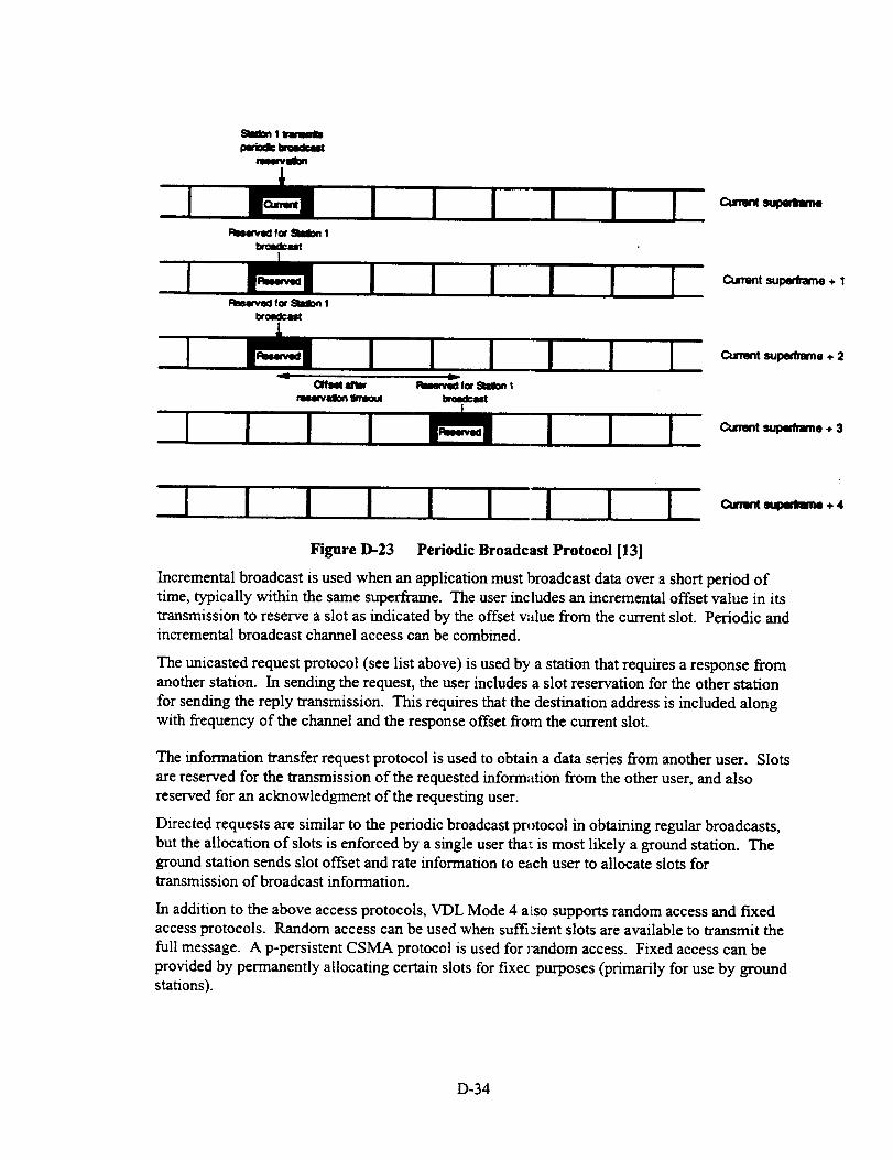
gUon 1 _
wm
FIm4tv_ for _ 1
bc_KP.,alt
Fle_tved for SIIIon 1
bnm{Icalz
(_f_ FIe_Pted f(_ Slmlon I
Czm_t superframe + 1
Cummt supedrame + 2
Cummt st.1)eC_ame + 3
Omnt _Ndmme ÷ 4
Figure D-23 Periodic Broadcast Protocol [13]
Incremental broadcast is used when an application must broadcast data over a short period oftime, typically within the same supcrframe. The user includes an incremental offset value in its
transmission to reserve a slot as indicated by the offset value from the current slot. Periodic andincremental broadcast channel access can be combined.
The unicasted request protocol (see list above) is used by a station that requires a response from
another station. In sending the request, the user includes a slot reservation for the other station
for sending the reply transmission. This requires that the destination address is included alongwith frequency of the channel and the response offset from the current slot.
The information transfer request protocol is used to obtain a data series from another user. Slots
are reserved for the transmission of the requested information from the other user, and also
reserved for an acknowledgment of the requesting user.
Directed requests are similar to the periodic broadcast protocol in obtaining regular broadcasts,
but the allocation of slots is enforced by a single user that is most likely a ground station. Theground station sends slot offset and rate information to e_ch user to allocate slots fortransmission of broadcast information.
In addition to the above access protocols, VDL Mode 4 also supports random access and fixedaccess protocols. Random access can be used when sufficient slots are available to transmit the
full message. A p-persistent CSMA protocol is used for _andom access. Fixed access can be
provided by permanently allocating certain slots for fixec purposes (primarily for use by groundstations).
D-34

ReservationTableMaintenanceandSlotSelectionProtocol
As each user receives bursts, slot reservation information is extracted and used to update the
Reservation Table. It is important that each user maintains a reservation table in order to
maintain the integrity of the slot selection process.
When preparing to make a reservation for an upcoming transmission, the user must determine
the amount of data to be transmitted (number of consecutive bursts) and then determines the
available number of slots in the reservation table. If a sufficient number of slots are available,
the user makes a selection and schedules the transmission accordingly. If there is not a sufficient
number of slots, the user can select from previously reserved slots by other users.
Two methods of borrowing slots are used: 1) slots that do not result in co-channel interference
(CCI), and 2) Robin Hood selection. CCI selection is illustrated in Figure D-24. Station I wants
to communicate with Station 2, but an insufficient number of slots are available for transmission.
In order to free up additional slots, Station 1 examines the reservation table to determine if it can
borrow slots from other reservations. It looks to find reservations between other user pairs
(Stations 3 and 4) that are more distant and would not be interfered with since the D/U of the
geometry is such that no CCI results.
Station 4
4. /a-_ Station 3
_ Station 1
Figure D-24 Slot Selection based on Co-Channel Interference Protection [131
The second method using previously reserved slots is to borrow them from aircraft that are at
long distances. This is referred to as Robin Hood and is illustrated in Figure D-25. The effect of
Robin Hood is to gracefully degrade the communications range as the channel loading increases.It is evident that a modulation waveform that is robust to co-channel interference, i.e., low D/U,
is critical for extending network capacity using CCI and Robin Hood.
Figure D-25 Slot Selection based on Robin Hood
D-35

Useof CCIandRobinHoodisacceptablefordatalink applicationssuchasADS-B.However,forCPDLCapplicationsit is importantthatthegroundcontrollermaintaincommunicationwithall aircraftwithin theintendedcoveragevolumeandthatuseof CCIandRobinHoodwouldnotbeacceptable.Qualityof serviceparametersareusedto controltheextent(if any)towhichCCIandRobinHoodareusedin theslotselectionprocess.
Observation:As thenetwork becomes more loaded, a substantial number of reservation table
calculations must be made in real time to determine future slot reservations, especially for CCI and
Robin Hood calculations. This is likely not a problem with the fast processors available today.
4.3.4 Data Link Layer (DLS sublayer) and Link Management
The data link services (DLS) sublayer used by VDL Mode 4 is similar to the one used by VDL
Modes 2 and 3. The same command and response AVLC protocol (Table D-4) is implemented.
The various access protocols described above and the slot reservation approach of the VSS
supports the DLS protocol.
The link management function of the data link layer of VDL Mode 4 uses the synchronization
bursts and the XID (exchange ID) frames to establish and maintain links between stations.
Synchronization bursts provide identity and position information of aircraft. XID frames providelink control information.
Global Signalling Channels
VDL Mode 4 plans to utilize a world-wide pair of Global Signalling Channels (GSCs) that
provide for communication control in all airspaces. These global signalling channels are used to
transmit VDL Mode 4 Directory of Service (DOS), which provides frequency channel
information on the various services that are available in _:heairspace of interest, e.g., AOC,GPS/GNSS data link, etc.. The two GSCs are also used for enroute ADS-B, where each aircraft
transmits synchronization bursts on an alternating 20 sec period on each channel for an effective
10 see update for ADS-B enroute surveillance.
4.3.5 Sub-Network Layer
The sub-network layer is the same for all VDL modes and is not discussed here.
4.3.6 VDL Mode 4 and ADS-B
The primary driver for VDL Mode 4 from a data link application perspective is ADS-B. Thus
this section examines VI)L Mode 4 use for ADS-B. As described in the previous sections, ADS-
B is inherently integrated into the VDL Mode 4 protoco'_s. GNSS time and position are key
elements in providing TDMA timing and channel / slot access. VDL Mode 4 supports periodic
broadcasts of aircraft state information (i.e., position, rate of change, aircraft identification,
trajectory change points, etc.) as part of its synchronization bursts.
Section 3.3 (Volume I report) presented ADS-B require_nents as developed in the ADS-B
MASPS. The ADS-B MASPS identifies the data link rc'quirements in terms of 1) information
content, 2) update rate, 3) coverage range, 4) and a number of required communication
performance factors such as latency, availability, integr ty, etc. needed to support ADS-B
applications. The typical ADS-B data report is -200 bis long. ADS-B report update rates for
enroute, terminal area, and surface operations are 12 seconds, 5 seconds, and 1 second,
respectively. Not all information fields must be updated at the maximum rate. Coverage range
requirements can be several miles up to 200 nmi depending on the end-user application.
D-36
An assessmentof VDL Mode4 datalink loadingandresourcerequirementsto supportADS-Bin thehigh-trafficLosAngeles(LA)Basinenvironmentis foundin [4]. TheLA Basinhasbeenidentifiedasaworstcasetrafficdensity.TrafficdensitiesfortheLA Basinusedin [4]areasfollows:1) 1000aircraftin enrouteairspace2) 750aircraftin terminalareaairspace3) 150aircraftonairportmovementareas(perairport)4) 100aircraftonclosely-spacedparallelapproaches(singleairport)5) 50airports,with10largeairportsarelocatedwithintheLA Basin.
Enroute Data Link Requirement
As indicated previously, VDL Mode 4 utilizes 4500 time slots per minute (i.e., 75 slots per see),
each slot transmitting 192 bits of information in a typical ADS-B synchronization burst.
Assuming that each synchronization burst / slot accommodates a single ADS-B report (to be
validated), a single narrowband VHF channel is capable of supporting up to 750 enroute aircraft
at a 10 second update rate. Thus two channels are required to meet the 1000 aircraft LA Basin
requirement for enroute ADS-B applications (with each aircraft transmitting on both channels at
a 20 sec rate per channel). The two VDL Mode 4 channels utilize - 66 % capacity for fixedADS-B synchronization bursts. An additional 25 % capacity is estimated for lower rate ADS-B
data (e.g., next trajectory change point, etc.). Also 10 % of capacity is anticipated for directory
of services (DOS) messages and autotuning messages. Thus both channels are fully loaded forthe worst case LA Basin enroute region.
VDL Mode 4 plans to use the two Global Signalling Channels (GSCs) to provide enroute ADS-
B, also providing DoS indicating other available services. GSCs typically utilize self-organizing
protocol, where all airspace users develop their own network timing via received synchronizationbursts, without need for ground control (i.e., directed services).
Terminal Area Data Link Requirements
With a 5 second update rate for ADS-B, - 375 (75*5) aircraft can be supported on a single
channel. Terminal area ADS-B is expected to be under ground control, i.e., a ground station
assigns time slots for user ADS-B transmissions. Autotuning commands require -3% loading.
Thus two ADS-B channels are needed for LA Basin terminal area ADS-B applications. The
same two frequencies are expected to be reused among all airports in the LA Basin due to the
relatively low D/U performance of 19.2 kbps GFSK (a low D/U waveform is absolutely essential
for VDL Mode 4 ADS-B data link). Aircraft are expected to be able to discriminate between the
desired (near) airport and undesired (more distant airports).
Surface Operations (ASMGCS) and Parallel Approaches (PRM) Data Link Requirements
[4] indicates one channel required for each application; Airport Surface Movement Guidance and
Control System (ASMGCS) and Precision Runway Monitoring (PRM). With - 1 second updaterates for moving aircraft / vehicles, some adaptive update rates for stationary or slow moving
aircraft / vehicles may be needed to achieve all ADS-B data link within a single channel for each,ASMGCS and PRM.
Summarizing VDL Mode 4 channel requirements from [4]:
1) 2 Global Signalling Channels (GSCs) for enroute ADS-B
2) 2 fi:equency channels for terminal area ADS-B
3) 1 frequency channel for the ASMGCS ADS-B application
4) 1 frequency channel for the PRM ADS-B application
D-37
Note: For VDL Mode 4 data link applications other than ADS-B, [4] estimates that four
frequencies are required for DGPS/DGNSS data link, and one frequency is required for
each, FIS-B and TIS-B. Thus a total of 10 frequencies are estimated to provide the above
services in the LA Basin (not including the two GSCs).
Due to the GSCs, the basic VDL Mode 4 radio configuration consists of two dedicated receivers
and one transmitter that tunes between the two GSC frequencies. Additional receivers and
perhaps additional transmitters are needed if additional services are included. The number of
dedicated transmitter and receiver modules required for x,rDL Mode 4 are highly dependent on
how many of the CNS/ATM data link applications are integrated within a particular radio
frequency.
The assumption in this paper is that data link application_ (e.g., CPDLC, AOC/AAC, FIS, ADS-B,
etc.) will primarily be maintained as separate services (by frequency) due to capacity constraints,
"separation of function" considerations, and institutional separation of services. Sections 3.4 and
3.5 (in Volume I report) examine CNS/ATM data link al:,plication allocation to various data links,
including VDL Mode 4, and develop data link architecture resource requirements.
In Sections 3.4 and 3.5 (Volume I), a dedicated ADS-B resource requirement of 2 transmitters
and 4 receivers is assumed, representing the worst case requirement when an aircraft transitions
between enroute and terminal area regions under ADS-B surveillance, in an LA Basin type of
environment. Both enroute and terminal area ADS-B must be maintained simultaneously in the
transition region. Two transmitters are assumed in ordel to allow independence between enroute
and terminal area ADS-B networks. It may be possible to use a single transmitter that can be
retuned to transmit on one of four frequencies as long as the occurrence of simultaneous transmit
requests to accommodate both ADS-B networks is low.
The above ADS-B loading estimates represent a worst c_tse traffic environment. Conversely, the
above estimates also assume 1) near perfect TDMA slot selection in a heavily loaded network
(self-organized and ground directed), 2) perfect message reception, i.e., no need for
retransmissions or higher update rates due to possible cerrupted messages, and 3) that a single
VDL Mode 4 slot is sufficient for sending an entire ADE:-B report. For high-density areas it is
possible that additional channels may be required to off, et any additional overhead due to
imperfect channel access (e.g., less than -90 %), messa_:e errors, and extra transmissions due to
longer message requirements. Further validation of the,, e effects is required.
Additional Considerations of VDL Mode 4 ADS-B
The following are additional factors that impact VDL Mode 4 ADS-B:
1) D/U ratio
2) Range guard time
3) Hidden user, net entry and reservation updates
4) Interoperability with TCAS
5) Frequency band.
D/U Ratio
A low D/U ratio is essential for VDL Mode 4 ADS-B olherwise the concept will not work. A
high D/U results in distant aircraft being able to interfere with the reception of ADS-B reports of
aircraft that are relatively close. In tracking an aircraft _thin 25 nmi, a D/U of 18 dB allows an
aircraft as far away as 200 nmi to interfere with signal reception. Similarly, tracking a 50 nmi
aircraft can be interfered with by an aircraft 400 nmi a_ay.
D-38

Twoaircraftlocatedeithersideof thereceivingaircraftmaynotbewithinradioline-of-sight(RLOS)andarethushidden(hiddenuser)andmayinadvertentlyselectthesameperiodictimeslotsassignmentsfor signaltransmission.Timeslotassignmentsareselectedbasedonaoneminute(onesuperframe)listeningintervalandaremaintainedfor 4to 8minutesbeforetheyarechanged.Thusanaircraftwithin25to 50nmimaybehiddenfor4 to8minutes,whichduetohighclosureratesisunacceptablefor safeoperations.A lowD/Uallowstheaircrafttodiscriminatebetweenthesetwoaircraft,andahiddenuserin thiscaseisnotaproblem.InadditionbyusingtwoGSCs,it isunlikelythatbothhiddenuserswill makethesametimeslotselectionsonbothchannels.
Fora lowD/Uof 6dB,anaircraftbeingtrackedat50nmicanbeinterferedwithbyotheraircraftwithin100nmiof thereceivingaircraft.Thetwotransmittingaircraftwill bewithinRLOSandwill makeappropriateslotreservationstoavoidselectingthesametimeslots.In hightrafficdensities,whereRobinHoodisusedto overridetimeslotassignmentsof distantusers,alowD/Uisalsobeneficial.
Anadditionalmarginin therequiredD/Umayberequiredto accountfor channeleffectsandgainimbalancesin transmittersandantennagains.TheextentofthismarginiscriticalindeterminingADS-Bperformanceandmustbeinvestigated.
RangeGuardTime
In ordertomaximizedatalinkthroughput,arangeguardtimeof-1.25msis availablein theVDLMode4timeslot,supporting-200nmirange.Forgroundstationsperforminglong-rangeADS-Bsurveillance,theguardtimemaybecomeanissue,althoughalowD/Uwill discriminatetothecloseraircraft.WhetherthisguardtimeselectionisadequateisTBD.
Hidden User, Net Entry, Reservation Updates
The hidden user was described above and becomes a problem when two aircraft are beyond
R.LOS of each other and inadvertently select the same time slots for transmitting ADS-B reports.
In addition, hidden users can occur when signals are blocked by terrain (e.g., mountains) or
buildings, etc., on the airport surface. In selecting slots, aircraft / ground vehicles maintain
reservation tables of the entire network (reservation information is included in transmitted
messages). These selections are typically made while monitoring the channel for 1 superframe
(1 minute). Reservations are maintained for 4 to 8 minutes, before a new series of periodic time
slots are selected. Thus it is possible that hidden users could stay hidden up to 8 minutes. Using
two independent channels reduces the possibility of message conflicts once users are visible,
even if the 8 minutes have not expired. Use of more frequent reservation updates (less than 4
minutes) in order to minimize the duration of possible message collisions due to hidden users
may be difficult in high traffic densities due to the excessive reservation changes by all users.
lnteroperability with TCAS
Section 3.3.2 (Volume I) discusses issues related to ADS-B surveillance and ACAS/TCAS.
Since ADS-B is also expected to support the ACAS application, interoperability with the current
TCAS is a requirement. Since TCAS currently uses the Mode-S link for surveillance and an air-
to-air resolution advisory link between aircraft, new interfaces to TCAS would likely be required
with VDL Mode 4 as the provider of ADS-B reports. Additional issues of independence of
ASAS and ACAS, and transition to a new ACAS based on VDL Mode 4 are also discussed in
Section 3.3.2 (Volume I).
D-39

Independence of Surveillance and Navigation Functions
The independence of surveillance and navigation for VDL Mode 4 is a potential concern. VDL
Mode 4 is dependent upon GPS/GNSS time and position information to maintain the data link,
while surveillance makes use of the same position information.
Frequency Band Issues
Currently, the VHF Comm band is designated for Aeronautical Mobile Route Services (AMRS) and
may not allow transmission of ADS-B surveillance information. In addition, the VHF frequency
band is already heavily congested and may not support additional requirements for ADS-B.
4.3.7 Mode-S and ADS-B
Mode-S is also a candidate for ADS-B data link and builds upon the existing Mode-S based
surveillance system (Secondary Surveillance Radar and TCAS). Mode-S utilizes a single, wide-
band high data rate channel, providing all airspace users with a seamless, global frequency
resource for transmitting ADS-B reports. Important issues with Mode-S for ADS-B are capacity,
range, and near omnidirectional coverage of a-ansmitting signals, i.e., absence of significant nulls.
Mode-S data link capacity and interference studies indicate that Mode-S is capable of meeting
ADS-B requirements for high-density traffic environments (-700 aircraft in LA Basin). In
addition, while previously the need for longer range surveillance was not a requirement for
airborne TCAS / Mode-S, additional range capabilities i_eeded for ADS-B are possible with these
systems and must be validated. Enhanced signal proces,mg of received ADS-B reports will be
needed to improve reception probability in high-density traffic areas. Omnidirectional antenna
patterns must be investigated. Upper and lower diversi_! receivers may be required for most
aircraft (current air transport aircraft already utilize diversity Mode-S systems). Table D-9
summarizes many of the key issues of ADS-B with respect to Mode-S and VDL Mode 4.
4.3.8 Summary of VDL Mode 4
VDL Mode 4 is a data only (i.e., no digital voice) data link that utilizes TDMA channel access
protocols for efficient channel utilization. The signalling rate is 19.2 kbps GFSK. TDMA time
slots are - 13.33 ms long with ~ 10 ms of the slot availa_)le for data transfer, which results in 192
bits per slot.
VDL Mode 4 makes integral use of GPS/GNSS time and position information for TDMA timing
and slot selection protocols. All airspace users exchange synchronization bursts (which include
position information) to develop system timing, allowing autonomous, self-organizing network
access. Channel access can also be controlled directly ky ground stations. In addition, VDL Mode
4 includes address and slot reservation information with in messages to allow all users to build andmaintain a network slot reservation table. This slot reservation table serves as the mechanism for
all users to reserve dedicated time slots for desired sigmd lxansmissions, thus minimizing slot
contention. As the network becomes more fully loade& it may become difficult to find available
slots. VDL Mode 4 utilizes position information on all users to override slot selection of distant
users or those that will not be affected by co-channel inlerference due to geometry.
A VDL Mode 4 user listens to network transmissions fcr one superframe (1 minute) before
selecting available time slots. Time slot selections are raaintained for 4 to 8 minutes before a new
reservation using different slots is made.
While VDL Mode 4 was originally intended for broadcast services, e.g., ADS-B, it also has
provisions for a range of addressed communications and slot reservation protocols and is thuscapable of providing a number of data link services. Sc me envision VDL Mode 4 to be a common
D-40
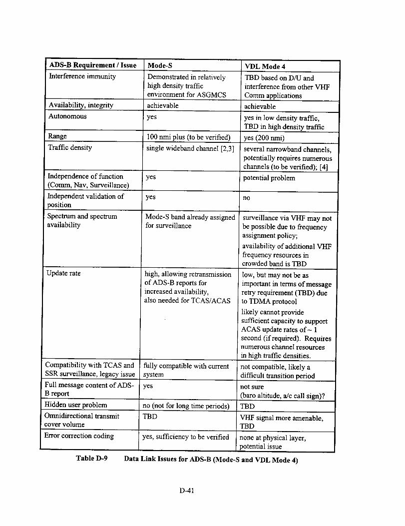
ADS-BRequirement / Issue Mode-S VDL Mode 4
Interference immunity Demonstrated in relatively TBD based on D/U and
high density traffic interference from other VHF
environment for ASGMCS Comm applications
Availability, integrity achievable achievable
Autonomous yes yes in low density traffic,
TBD in high density traffic
Range 100 nmi plus (to be verified) yes (200 nmi)
Traffic density single wideband channel [2,3] several narrowband channels,
potentially requires numerous
channels (to be verified); [4]
Independence of function yes potential problem
(Comm, Nav, Surveillance)
Independent validation of yes no
position
Spectrum and spectrum
availability
Update rate
Mode-S band already assignedfor surveillance
high, allowing retransmission
of ADS-B reports for
increased availability,also needed for TCAS/ACAS
surveillance via VHF may not
be possible due to frequency
assignment policy;
availability of additional VI-IF
frequency resources incrowded band is TBD
low, but may not be as
important in terms of message
retry requirement (TBD) due
to TDMA protocol
likely cannot provide
sufficient capacity to support
ACAS update rates of- 1
second (if required). Requiresnumerous channel resources
in high traffic densities.
Compatibility with TCAS and fully compatible with current not compatible, likely a
SSR surveillance, legacy issue system difficult transition period
Full message content of ADS- yes not sure
B report (baro altitude, a/c call sign)?
Hidden user problem no (not for long time periods) TBD
Omnidirectional transmit TBD VHF signal more amenable,cover volume TBD
Error correction coding yes, sufficiency to be verified none at physical layer,
potential issue
Table D-9 Data Link Issues for ADS-B (Mode-S and VDL Mode 4)
D-41

CNS/ATMdatalink forCPDLC,AOC/AAC,FIS,FIS-B,TIS-B and ADS-B data link
applications. VDL Mode 4 is capable of both ATN-compatible and VHF Specific Services
(VSS) data link. VSS supports low-latency tactical communications.
While VDL Mode 4 has many attractive features and capabilities, there are also a number of
potential shortcomings. VDL Mode 4, like VDL Mode 3 is considerably more complex than
VDL Mode 2. This is primarily due to the TDMA protoc.3l. In addition VDL Mode 4 is highly
dependent on precise timing from GPS/GNSS and uses minimal guard times to attain maximum
channel data rate. The VDL Mode 4 network, while extremely flexible, does not appear as
robust even as VDL Mode 3, which uses centralized timing control from ground stations.
"Separation of function" of communications, navigation and surveillance is an important
consideration for VDL Mode 4 ,which has a tendency to promote integration of these functions.
CNS separation of function, i.e., independence among these functions to avoid common failures,
is an important concept in conducting airspace operations.
VDL Mode 4 is highly reliant on low D/U performance o-'the 19.2 kbps GFSK waveform inorder to avoid co-channel interference effects. The robustness of the waveform reduces the
available signalling rate to 19.2 kbps. The lower signalling rate along with the associated time
slot structure may be inadequate for some high data rate applications such as ADS-B, requiring
additional channel resources. It is possible that a bank of VHF channel resources requiring
multiple VHF receiver and transmitter modules may be required to satisfy the future CNS/ATM
data link requirements. Since the VHF spectrum is already at a premium, allocation of additional
services to the V/IF band (e.g., ADS-B surveillance) ma3 not be possible.
Since VDL Mode 4 is envisioned by some for providing he ADS-B data link, significant issues
arise in terms of the current legacy TCAS / Mode S surveillance system. Since ADS-B is
expected to support separation assurance and collision a,, oidance applications, additional
interfaces to TCAS are required. Dual equipage is likely needed during any transition phase
before a VHF-based ADS-B and ACAS system can evolve. Since Mode-S is envisioned by
some to be the ADS-B data link, with little additional modifications to the current system, a
VDL Mode 4 solution may not be cost effective.
For VHF Comm applications, VDL Mode 4 does not provide digital voice capability and thus
additional, dedicated radio resources are required to pro', ide both voice and data link services.
The competing VDL Mode 3 offers integrated voice and data services simultaneously over the
same frequency channel and does not require additional radio resources. In addition, the 31.5
kbps signalling rate supports four voice channels on a single VHF 25 KHz channel and thus
provides efficient frequency use in the crowded VI-IF spectrum. Use of 8.33 KHz analog voice
channels in concert with VDL Mode 4 data link may als(, provides more efficient channel
utilization, but requires separate radios.
While VDL Mode 4 provides the potential for a unified data link solution for all CNS/ATM data
link applications, there are also numerous potentially ser _ous issues of its use as the end-state
CNS/ATM data link for all or even some of these applications. In order to totally resolve these
issues will require significant validation activity. At the same time, the industry has been forgingahead with definition and development of Mode-S ADS-B and VDL Mode 2 and 3 for ATC/ATS
data link, with substantial investments in time (i.e., man'., man years of effort have been spent).
VDL Mode 4 is a relative newcomer to the various ICA() and RTCA industry committees that are
developing data link applications and may have a diffic_ It time gaining acceptance since other
solutions are already well along in the development and validation phase. Table D-10 summarizes
the performance of VDL Mode 4.
D-42

Communications Performance
Throughput delay capable of very low latencies due to VHF
Specific Services
Message integrity, priority yes
ATN Compatibility yes
VHF Specific Services (VSS), i.e., non-ATN yes
Broadcast Capability yes
Voice/Data data only
19.2 kbps GFSK D/U of- 6dB for frequency reuse
Table D-10 VDL Mode 4 Communications Performance Summary
D-43

4.4 Comparison of VDL Modes 2, 3 and 4
Table D- 11 provides a summary comparison of characteristics and capabilities of the variousVDL modes.
VDL Mode 2 VDL Mode 3 VDL Mode 4
air-ground comms air-ground comms air-ground, air-air comms
ATN-compatible ATN-compatible ATN-compatible
(addressed comms) (addressed comms) (addressed comms)
currently no VHF specific currently no VHF specific VSS capability for local,
services (VSS), i.e., non-ATN, services (VSS), i.e., nor-ATN, tactical communications
capability capability
not well suited for broadcast broadcast capableideally suited for simplex
broadcast (some minormodifications to current
protocols required)
CSMA (efficient channel TDMA (high efficiency TDMA (high efficiencyaccess for low channel traffic) channel access possible J channel access possible)
simple protocols, timing complex, protocols, tim ing complex protocols, timing
high latency low to moderate latency low latency
data only simultaneous voice and data data only
31.5 kbps D8PSK 31.5 kbps D8PSK 19.2 kbps D8PSK
high D/U (16 to 20 dB) high D/U (16 to 20 dB) low D/U (-6 dB)to be verified
linear power amplifier linear power amplifier nonlinear amplifier
required required
not a candidate for ADS-B not a candidate for AD';-B ADS-B candidate, capability
requires validation
(see Table D-9).
N/A adequate range guard times range guard times marginal
frequency reuse is TBD frequency reuse is TBE frequency reuse is TBD
(function of coverage volume (function of coverage w_lume (function of coverage volume
and DFU margin) and D/U margin) and D/U margin)
can meet integrity, availability can meet integrity, availability can meet integrity, availability
Table D-11 Summary of VDL Characteristics
D-44

REPORT DOCUMENTATION PAGE Fo_A_OMB No, 0704-0188
Public reporting burden for this collection of infon_ation is estimated to average 1 hour per response, ioclucling the time for reviewing instructions, searching existing data sources,gathering and maintaining the data needed, and coml:Y,ating and rewm,/ing the collection of information. Send comments regarding this burden estimate or any other aspect of thiscollection of information, including suggestions for reducing this burden, to Washington Headquaders Sennces, Directorste for Information Operations and Reports, 1215 JeffersonDavis Highway, Suite 1204, Arlington, VA 22202-4302, and to the Office of Management and Budget, Papenvork Reduction Project (0704-0188), Washington, DC 20503.
1. AGENCY USE ONLY (Leave blank) 2. REPORT DATE
Jul_ 19984. TITLE AND SUBTITLE
Integrated Airport Surface Operations
6. AUTHOR(S)
S. Koczo
7. PERFORMINGORGANIZATIONNAME(S)ANDADDRESS(ES)Rockwell Collins Avionics and Communications
Advanced Technology Center
Cedar Rapids, IA 52498-0120
9. SPONSORING/MONITORING AGENCY NAME(S) AND ADDRESS(ES)
National Aeronautics and Space Administration
Langley Research Center
Hampton, VA 23681-2199
3. REPORTTYPEANDDATESCOVEREDContractor Report5. FUNDINGNUMBERS
NAS 1- 19704Task 16
538-04-13-02
8. PERFORMING ORGANIZATIONREPORT NUMBER
10. SPONSORING/MONITORINGAGENCY REPORT NUMBER
NASA/CR- i 998-208441
11. SUPPLEMENTARY NOTES
Langley Technical Monitor: Steven D. Young
1211. DISTRIBUTION/AVAILABILITY STATEMENT 12b. DISTRIBUTION CODE
Unclassified-Unlimited
Subject Category 04 Distribution: Nonstandard
Availability: NASA CASI (301 ) 621-039013. ABSTRACT (Maximum 200 words)
The current air traffic environment in airport terminal areas experiences substantial delays when weather
conditions deteriorate to Instrument Meteorological Conditions (IMC). Research activity at NASA has
culminated in the development, flight test and demonstration of a prototype Low Visiblity Landing and SurfaceOperations (LVLASO) system. A NASA led industry team and the FAA developed the system which integrated
airport surface surveillance systems, aeronautical data links, DGPS navigation, automation systems, and
controller and flight deck displays. The LVLASO system was demonstrated at the Hartsfield-Atlanta
International Airport using a Boeing 757-200 aircraft during August, 1997. This report documents the
contractors role in this testing particularly in the area of data link and DGPS navigation.
14. SUBJECT TERMS
Aeronautical Data Link, Surveillance, ADS-B, Air Traffic Management,
DGPS navigation.
17. SECURITY CLJlrSIRCATICIN 111.SECURITYCI..,aSSIRCATIO_I 19. SECURITY CLASSlRCATIONOF REPORT OF THIS PAGE OF ABSTRACT
Unclassified Unclassified Unclassified
NSN 7540-01-280-5500
15. NUMBER OF PAGES
17316. PRICE CODE
A0820. LIMITATION
OF ABSTRACT
Standard Form 298 (Rev. 2-89)Prescribe0 by ANSI Std. Z.39-18298-102