Embed Size (px)
Citation preview
Air Navigation Order (ANO)
For
Instrument Flight Procedure (IFP) Design Criteria
ANO (IFP Design Criteria) A.I
First Edition, June 2011
Civil Aviation Authority Bangladesh.

INSTRUMENT FLIGHT PROCEDURE (IFP) DESIGN CRITERIA-CAAB ANO A.I
JUNE 2011 Page 2 of 45
TABLE OF CONTENTS
Amendment Records 3 Foreword 4
1 DEFINITIONS 5
2 ABBREVIATIONS AND ACRONYMS 9
3 RELATED DOCUMENTS 11
4 AERODROME OPERATING MINIMA 12
5 PROCEDURE NAMING & CHARTING 13
6 PROMULGATION 13
7 SAFETY ASSESSMENT, DESIGN APPROVAL & AUTORIZATION 14
8 THE INSTRUMENT FLIGHT PROCEDURE DESIGN PROCESS 16
9 DESIGNER QUALIFICATIONS AND TRAINING 17
10 PROCEDURE DESIGN INFORMATION ACQUISITION 18
11 PROCEDURE DESIGN 18
12 NORMAL AND EMERGENCY OPERATIONS 19
13 PROCEDURE DESIGN DOCUMENTATION 19
14 REVIEW OF PROCEDURE & RETENSION OF DOCUMENTS 20
15 GROUND AND FLIGHT VALIDATION 20
16 FLIGHT VALIDATION/INSPECTION PILOT’S QUALIFICATION 22
17 PROCEDURE DESIGN AUTOMATION 22
18 GUIDANCE ON ENVIRONMENTAL ISSUES 22
19 DEPARTURE PROCEDURES 23
20 STANDARD INSTRUMENT ARRIVAL ROUTES (STARs) 27
21 INSTRUMENT APPROACH PROCEDURES 28
22 INITIAL APPROACH SEGMENT 32
23 INTERMEDIATE APPROACH SEGMENT 34
24 FINAL APPROACH SEGMENT 36
25 MISSED APPROACH SEGMENT 39
26 MINIMUM SECTOR ALTITUDES (MSA) 41
27 PRECISSION APPROACH PROCEDURE 43
28 LOCALIZER (LLZ) ONLY 45
29 GNSS RNAV, RNP & BARO-VNAV APPROACH PROCEDURE 45
30 REVISION OF THIS ANO 45

INSTRUMENT FLIGHT PROCEDURE (IFP) DESIGN CRITERIA-CAAB ANO A.I
JUNE 2011 Page 3 of 45
AMENDMENT RECORDS
The amendments listed below have been incorporated into this copy of ANO of Instrument Flight Procedure Design
Amendment
No. Version
No. Subject Source Section
affectedEntered
by (with Date)
Approved by
(with Date)
Effective Date

INSTRUMENT FLIGHT PROCEDURE (IFP) DESIGN CRITERIA-CAAB ANO A.I
FOREWORD
The Air Tratfic Services and Aerodromes (ATS/Aerodromes) Division of the Civil AviationAuthority of Bangladesh is responsible for the regulation of ATS and air navigation services inBangladesh airspace. This division also responsible for developing and promulgatingappropriate. clear and concise ATS & ANS safbty standards.
This Air Navigation Order (ANO) on Instrument Flight Procedure Design Criteria has beenissued in pursuance of Rule 4 of the preliminary part of Civil Aviation Rules 1984. It spells outthe standards and requirements to be met by the instrument flight procedure design office and
instrument flight procedure designers for the design and maintenance of instrument flightprocedures. The standards and requirements in this ANO are based mainly on ICAO Document8168, Procedures for Air Navigation Services, Aircrafi Operations: PANS-OPS. Vol-ll and
Quality Assurance Manual for Flight Procedure Design Doc. 9906 Vol. I & V, with suchmodifications as determined b-v the ATS & Aerodromes Division, to be applicable inBangladesh.
Amendments to this ANO are the responsibility of the ATS & Aerodromes Division. The ATS& Aerodromes Division may wish to supplement/amend the standards and requirements in thisANO in the fbrm of Safety Directives, Saf-ety Publications or Information Circulars or whereappropriate, such publications or circulars will be incorporated into this ANO by amendmentfrom time to time.
Users of this ANO should forward advice of errors, inconsistencies or suggestions fbrimprovement to this ANO to the addressee stipulated below.
--:t1t--"--L,tx er.----Jt.) !r.-- L- i t
Chairman-Civil Aviation Authority of Bangladesh,Headquarters,Kurmitola. Dhaha- 1 229.
INSTRUMENT FLIGHT PROCEDURE (IFP) DESIGN CRITERIA-CAAB ANO A.I
JUNE 2011 Page 5 of 45
1. DEFINITIONS When the following terms are used in this document, they have the following meanings: Aerodrome elevation. The elevation of the highest point of the landing area. Aerodrome Operating Minima : The limits of usability of an aerodrome either for take-off or landing usually expressed in terms of visibility or Runway visual range, decision altitude/height or Minimum Descent altitude/height and cloud conditions. Along-track tolerance (ATT). A fix tolerance along the nominal track resulting from the airborne and ground equipment tolerances. Altitude. The vertical distance of a level, a point or an object considered as a point, measured from mean sea level (MSL). Base turn. A turn executed by the aircraft during the initial approach between the end of the outbound track and the beginning of the intermediate or final approach track. The tracks are not reciprocal. Note.— Base turns may be designated as being made either in level flight or while descending, according to the circumstances of each individual procedure. . Circling approach. An extension of an instrument approach procedure which provides for visual circling of the aerodrome prior to landing. Cross-track tolerance (XTT). A fix tolerance measured perpendicularly to the nominal track resulting from the airborne and ground equipment tolerances and the flight technical tolerance (FTT). Decision altitude (DA) or decision height (DH). A specified altitude or height in the precision approach or approach with vertical guidance at which a missed approach must be initiated if the required visual reference to continue the approach has not been established. Elevation. The vertical distance of a point or a level, on or affixed to the surface of the earth, measured from mean sea level. Final approach segment. That segment of an instrument approach procedure in which alignment and descent for landing are accomplished. Final approach track. The flight track in the final approach segment that is normally aligned with the runway centre line. Flight procedure designer. A person responsible for flight procedure design who meets the competency requirements as laid down by the State. . Heading. The direction in which the longitudinal axis of an aircraft is pointed, usually expressed in degrees from North (true, magnetic, compass or grid).

INSTRUMENT FLIGHT PROCEDURE (IFP) DESIGN CRITERIA-CAAB ANO A.I
JUNE 2011 Page 6 of 45
Height. The vertical distance of a level, a point or an object considered as a point, measured from a specified datum. Holding procedure. A predetermined manoeuvre which keeps an aircraft within a specified airspace while awaiting further clearance. Initial approach fix (IAF). A fix that marks the beginning of the initial segment and the end of the arrival segment, if applicable. Initial approach segment. That segment of an instrument approach procedure between the initial approach fix and the intermediate approach fix or, where applicable, the final approach fix or point. Instrument approach procedure (IAP). A series of predetermined manoeuvres by reference to flight instruments with specified protection from obstacles from the initial approach fix, or where applicable, from the beginning of a defined arrival route to a point from which a landing can be completed and thereafter, if a landing is not completed, to a position at which holding or en-route obstacle clearance criteria apply. Instrument approach procedures are classified as follows:
Non-precision approach (NPA) procedure. An instrument approach procedure which utilizes lateral guidance but does not utilize vertical guidance. Approach procedure with vertical guidance (APV). An instrument procedure which utilizes lateral and vertical guidance but does not meet the requirements established for precision approach and landing operations. Precision approach (PA) procedure. An instrument approach procedure using precision lateral and vertical guidance with minima as determined by the category of operation.
Intermediate approach segment. That segment of an instrument approach procedure between either the intermediate approach fix and the final approach fix or point, or between the end of a reversal, racetrack or dead reckoning track procedure and the final approach fix or point, as appropriate. Intermediate fix (IF). A fix that marks the end of an initial segment and the beginning of the intermediate segment. Minimum descent altitude (MDA) or minimum descent height (MDH). A specified altitude or height in a nonprecision approach or circling approach below which descent must not be made without the required visual reference. . Minimum obstacle clearance altitude (MOCA). The minimum altitude for a defined segment that provides the required obstacle clearance. Minimum sector altitude (MSA). The lowest altitude which may be used which will provide a minimum clearance of 300 m (1 000 ft) above all objects located in an area contained within a sector of a circle of 46 km (25 NM) radius centred on a radio aid to navigation.

INSTRUMENT FLIGHT PROCEDURE (IFP) DESIGN CRITERIA-CAAB ANO A.I
JUNE 2011 Page 7 of 45
Missed approach point (MAPt). That point in an instrument approach procedure at or before which the prescribed missed approach procedure must be initiated in order to ensure that the minimum obstacle clearance is not infringed. Missed approach procedure. The procedure to be followed if the approach cannot be continued. Mountainous area. An area of changing terrain profile where the changes of terrain elevation exceed 900 m (3 000 ft) within a distance of 18.5 km (10.0 NM). Obstacle assessment surface (OAS). A defined surface intended for the purpose of determining those obstacles to be considered in the calculation of obstacle clearance altitude/height for a specific APV or precision approach procedure. Obstacle clearance altitude (OCA) or obstacle clearance height (OCH). The lowest altitude or the lowest height above the elevation of the relevant runway threshold or the aerodrome elevation as applicable, used in establishing compliance with appropriate obstacle clearance criteria. Precision approach procedure. An instrument approach procedure utilizing azimuth and glide path information provided by ILS or PAR. Primary area. A defined area symmetrically disposed about the nominal flight track in which full obstacle clearance is provided. (See also Secondary area.) Procedure altitude/height. A specified altitude/height flown operationally at or above the minimum altitude/height and established to accommodate a stabilized descent at a prescribed descent gradient/angle in the intermediate/final approach segment. Procedure turn. A manoeuvre in which a turn is made away from a designated track followed by a turn in the opposite direction to permit the aircraft to intercept and proceed along the reciprocal of the designated track. Racetrack procedure. A procedure designed to enable the aircraft to reduce altitude during the initial approach segment and/or establish the aircraft inbound when the entry into a reversal procedure is not practical. Reference datum height (RDH). The height of the extended glide path or a nominal vertical path at the runway threshold. Reversal procedure. A procedure designed to enable aircraft to reverse direction during the initial approach segment of an instrument approach procedure. The sequence may include procedure turns or base turns. Secondary area. A defined area on each side of the primary area located along the nominal flight track in which decreasing obstacle clearance is provided. (See also Primary area.) Significant obstacle. Any natural terrain feature or man-made fixed object, permanent or temporary, which has vertical significance in relation to adjacent and surrounding features and which is considered a potential hazard to the safe passage of aircraft in the type of operation for which the individual procedure is designed.

INSTRUMENT FLIGHT PROCEDURE (IFP) DESIGN CRITERIA-CAAB ANO A.I
JUNE 2011 Page 8 of 45
Standard instrument arrival (STAR). A designated instrument flight rule (IFR) arrival route linking a significant point, normally on an ATS route, with a point from which a published instrument approach procedure can be commenced. Standard instrument departure (SID). A designated instrument flight rule (IFR) departure route linking the aerodrome or a specified runway of the aerodrome with a specified significant point, normally on a designated ATS route, at which the en-route phase of a flight commences. Terminal arrival altitude (TAA). The lowest altitude that will provide a minimum clearance of 300 m (1 000 ft) above all objects located in an arc of a circle defined by a 46 km (25 NM) radius centred on the initial approach fix (IAF), or where there is no IAF on the intermediate approach fix (IF), delimited by straight lines joining the extremity of the arc to the IF. The combined TAAs associated with an approach procedure shall account for an area of 360 degrees around the IF. Threshold (THR). The beginning of that portion of the runway usable for landing. Track. The projection on the earth’s surface of the path of an aircraft, the direction of which path at any point is usually expressed in degrees from North (true, magnetic or grid). Visual manoeuvring (circling) area. The area in which obstacle clearance should be taken into consideration for aircraft carrying out a circling approach.
INSTRUMENT FLIGHT PROCEDURE (IFP) DESIGN CRITERIA-CAAB ANO A.I
JUNE 2011 Page 9 of 45
2. ABBREVIATIONS AND ACRONYMS
AIP Aeronautical Information Publication ALS Aeronautical Lighting System AMSL Above mean sea level ARP Aerodrome reference point APV Approach procedures with vertical guidance ATC Air traffic control ATS Air traffic services ATT Along-track tolerance BV Buffer value CAAB Civil Aviation Authority of Bangladesh. CAT Category CDI Course deviation indicator CRM Collision Risk Model DA/H Decision altitude/height DER Departure end of the runway DME Distance measuring equipment FAF Final approach fix FAP Final approach point FATO Final approach and take-off area FMC Flight management computer FMS Flight management system FTT Flight technical tolerance FL Flight level GP Glide path GPA Glide path angle HF Holding/racetrack to a fix HL Height loss IAF Initial approach fix IAP Instrument approach procedure IAS Indicated airspeed IF Intermediate approach fix IFP Instrument flight procedure IFR Instrument flight rules ILS Instrument landing system IMC Instrument meteorological conditions ISA International standard atmosphere LOC Localizer MA/H Minimum altitude/height MAHF Missed approach holding fix MAPt Missed approach point MATF Missed approach turning fix MDA/H Minimum descent altitude/height MM Middle marker MOC Minimum obstacle clearance MOCA Minimum obstacle clearance altitude MSA Minimum sector altitude MSD Minimum stabilization distance
INSTRUMENT FLIGHT PROCEDURE (IFP) DESIGN CRITERIA-CAAB ANO A.I
JUNE 2011 Page 10 of 45
MSL Mean sea level NM Nautical mile NPA Non-precision approach OAS Obstacle assessment surface OCA/H Obstacle clearance altitude/height OCS Obstacle clearance surface OJT On-the-job training OLS Obstacle limitation surface OM Outer marker PA Precision approach PANS-OPS Procedure for Air Navigation Services – Aircraft Operations PDG Procedure design gradient PinS Point-in-space approach RAIM Receiver autonomous integrity monitoring RDH Reference datum height (for APV and PA) SI International system of units SID Standard instrument departure SOC Start of climb STAR Standard instrument arrival TAA Terminal arrival altitude TA/H Turn at an altitude/height TAR Terminal area surveillance radar TAS True airspeed THR Threshold TMA Terminal control area TP Turning point VPA Vertical path angle VSS Visual segment surface WGS World geodetic system XTT Cross-track tolerance

INSTRUMENT FLIGHT PROCEDURE (IFP) DESIGN CRITERIA-CAAB ANO A.I
JUNE 2011 Page 11 of 45
3. RELATED DOCUMENTS 3.1 For the guidance in standards & recommended practices in IFP Design, which are not included in this ANO, the current versions of the following documents will be read and used in conjunction with this ANO:
(a) ICAO Doc 8168 Volumes I and II - Procedures for Air Navigation Services
– Aircraft Operations (PANS-OPS) (b) ICAO Doc 9368 IFP Construction Manual (c) ICAO Doc 9371 Template Manual (d) ICAO Doc 9724 CRM Manual (e) ICAO Doc 9365 All Weather Operations Manual (f) Doc. 9906 Vol. I & V Quality Assurance Manual for Flight Procedure
Design (g) ICAO Doc 9613 Manual of Required Navigation Performance
(RNP) (h) ICAO Doc 9573 RNAV Operations (i) ICAO Doc 9674 World Geodetic System 1984 (WGS 84) Manual (j) ICAO Doc 8697 Aeronautical Chart Manual (k) ICAO Annex 2 Rules of the Air (l) ICAO Annex 4 Aeronautical Charts (m) ICAO Annex 5 Units of Measurement (n) ICAO Annex 6 Aircraft Operations (o) ICAO Annex 11 Air Traffic Services (p) ICAO Annex 14 Vol I Aerodromes (q) ICAO Annex 14 Vol II Heliports (r) ICAO Annex 15 Aeronautical Information Services
3.2 Where there is a difference between a standard in this ANO and that of the above-mentioned ICAO documents, the standard in this ANO shall prevail. 3.3 When the IFP design office is not able to comply with any standards or recommended practices specified or referenced in ICAO documents or in this ANO, the design office shall apply to ATS/Aerodrome Division for exemption or deviation. Applications shall be supported in writing with the reasons for such exemption or deviation including any safety assessment or other studies undertaken and where appropriate, an indication of when compliance with the current standards can be expected. 3.4 Any exemption or deviation granted to the IFP design office shall also be recorded in the operations manual. The operations manual shall also contain the details of the exemption or deviation, such as the reason that the exemption or deviation was requested and any resultant limitations or conditions imposed.
INSTRUMENT FLIGHT PROCEDURE (IFP) DESIGN CRITERIA-CAAB ANO A.I
JUNE 2011 Page 12 of 45
4. AERODROME OPERATING MINIMA
4.1 Procedure designers shall establish & publish OCA/H, MSA (TAA), RDH and Procedure Altitude/Height for each instrument approach procedure and circling procedure in accordance with ICAO PANS-OPS DOC 8168, Vol-II. 4.2 Aerodrome operating minima related with MDA/H shall be established by the Aircraft Operators in accordance with their procedure. 4.3 Unless otherwise instructed by special order, circular or directives by the appropriate authority, visibility minima for all non precision instrument flight procedure shall be 2400 meters for CAT-C & CAT-D aircraft, 2000M for CAT-B and 1600M for CAT-A. 4.4 Unless otherwise instructed by special order, circular or directives by the appropriate authority, visibility minima for circling approach, if included, shall be 3000M. 4.5 Unless otherwise instructed by special order, circular or directives by the appropriate authority, the visibility minima for CAT-I ILS shall be 800M when LLZ, GP & ALS are available & operating normal. 4.6 Unless otherwise instructed by special order, circular or directives by the appropriate authority, the visibility minima for CAT-I ILS shall be 1400M when LLZ & GP are available & operating normal but ALS is out of service. 4.7 Unless otherwise instructed by special order, circular or directives by the appropriate authority, the visibility minima for CAT-I ILS shall be 2400M when LLZ & ALS are available & operating normal but GP is out of service. 4.8 Higher or Lower minima for visibility may be considered if required by the ATC or operator and if traffic situation, aircraft type involved, evaluation of obstacle/ terrain position around the airfield and/or Nav. Aids performance permits. However, consent of the appropriate authority must be taken in this regard.

INSTRUMENT FLIGHT PROCEDURE (IFP) DESIGN CRITERIA-CAAB ANO A.I
JUNE 2011 Page 13 of 45
5. PROCEDURE NAMING & CHARTING 5.1 Instrument approach, arrival & departure procedures shall be named in accordance with the naming convention contained in ICAO PANS-OPS DOC 8168, Vol.-II. 5.2 SCALE OF MAPS 5.2.1 The following scale of maps should be used for plotting instrument flight procedure segments: (a) 1:1000,000 and 1:500,000 for initial calculation of minimum sector altitudes.
(b) 1:250,000 for confirmation of minimum sector altitude, standard arrival routes, racetrack and reversal areas, initial, intermediate and missed approach segments. (c) 1:100,000 and 1:50.000 for detail checks within racetrack/reversal areas, intermediate areas, final approach area and missed approach area. (d) 1:25,000 and 1:10,000 for check of the ILS precision segment and preparation of obstacle data for CRM.
5.3 CHARTING FOR AIP
5.3.1 Publication procedure of charts to be followed is contained in: a) Standard Departure Chart — Instrument (SID) — ICAO Annex 4, Chapter 9; b) Standard Arrival Chart — Instrument (STAR) — ICAO Annex 4, Chapter 10; &
c) Instrument Approach Chart — ICAO Annex 4, Chapter 11. 5.4 CHARTING ACCURACY
5.4.1 Charting accuracy must be taken into account by applying vertical and horizontal tolerances, in accordance with ICAO PANS-OPS DOC 8168, Vol-II. “Charting accuracy”. When the application of these tolerances creates an unacceptable operational penalty, additional survey information should be used to refine the obstacle location and height data.
6. PROMULGATION 6.1 The promulgation of the instrument flight procedures in AIP Bangladesh shall be undertaken by Aeronautical Information Service (AIS) section under ATS/Aerodromes Division in accordance with relevant applicable provisions. 6.2 Procedure designers shall ensure that all important and necessary information pertaining to safety of air navigation has been depicted on the charts.
INSTRUMENT FLIGHT PROCEDURE (IFP) DESIGN CRITERIA-CAAB ANO A.I
JUNE 2011 Page 14 of 45
7. SAFETY ASSESSMENT, DESIGN APPROVAL & AUTORIZATION
7.1. SAFETY ASSESSMENT 7.1.1 The IFP design office shall carry out a safety assessment in respect of proposals for new flight procedure designs or any significant changes in a revised procedure. Proposals shall be implemented only when the assessment has shown that an acceptable level of safety will be met. 7.1.2 The safety assessment shall consider relevant factors determined to be safety-significant, including but not limited to:
(a) types of aircraft and their performance characteristics, including navigation capabilities and navigation performance; (b) traffic density and distribution; (c) airspace complexity; ATS route structure and classification of the airspace; (d) aerodrome layout (e) type and capabilities of ground navigation systems (f) any significant local or regional data (e.g. obstacles, infrastructures, operational factors, etc).
7.1.3 Safety risk control/mitigation process shall include hazard/consequence identification and safety risk assessment. Once hazards and consequences have been identified and safety risks assessed, the effectiveness and efficiency of existing aviation system defenses relative to the hazards and consequences should be evaluated. As a consequence of this evaluation, existing defenses shall be reinforced, new ones introduced, or both. 7.1.4 As part of the safety assurance, the risk control/ mitigation process shall include a system of feedback. This is to ensure integrity, efficiency and effectiveness of the defences under the new operational conditions. 7.1.5 The IFP design office shall ensure that the results and conclusions of the safety assessment and mitigation process of a new or changed procedure are specifically documented, and that this documentation is maintained throughout the life of the instrument flight procedure.

INSTRUMENT FLIGHT PROCEDURE (IFP) DESIGN CRITERIA-CAAB ANO A.I
JUNE 2011 Page 15 of 45
7.2 DESIGN APPROVAL & AUTORIZATION 7.2.1 IFP Design office shall obtain approval from the Chairman, CAAB before undertaking instrument flight procedure design. 7.2.2 IFP Design office shall ensure that adequate and competent personnel are assigned the task of construction of visual and instrument flight procedure design. 7.2.3 A person shall not act as a procedure designer unless specifically authorized by the Chairman, CAAB. The minimum qualification required for procedure designers are prescribed in Chapter-9 of this ANO.
INSTRUMENT FLIGHT PROCEDURE (IFP) DESIGN CRITERIA-CAAB ANO A.I
JUNE 2011 Page 16 of 45
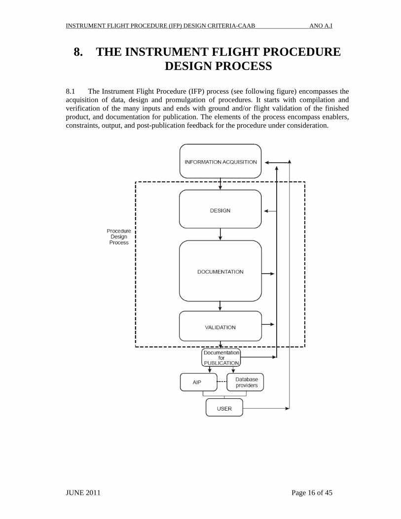
8. THE INSTRUMENT FLIGHT PROCEDURE DESIGN PROCESS
8.1 The Instrument Flight Procedure (IFP) process (see following figure) encompasses the acquisition of data, design and promulgation of procedures. It starts with compilation and verification of the many inputs and ends with ground and/or flight validation of the finished product, and documentation for publication. The elements of the process encompass enablers, constraints, output, and post-publication feedback for the procedure under consideration.

INSTRUMENT FLIGHT PROCEDURE (IFP) DESIGN CRITERIA-CAAB ANO A.I
JUNE 2011 Page 17 of 45
9. DESIGNER QUALIFICATIONS AND TRAINING
9.1 The procedure designer must have ATC or Pilot background. 9.2 Training for flight procedure designer should at least include an initial, advance and recurrent training at periodic intervals. 9.3 Initial training shall ensure that the flight procedure designer is able to demonstrate a basic level of competency that includes at least the following elements:
a) knowledge of information contained in the PANS-OPS, Doc 8168 Volumes I & II, other related ICAO provisions, ANO and related directives relevant to the flight procedure designer; (b) knowledge of general criteria in IFP designing; (c) skills in the non-precision approach design; (d) skills in the precision approach design; (e) skills in the instrument departure designs; (f) knowledge of the criteria for RNAV, GNSS and RNP; and (g) practical exercises in the design of procedures.
9.4 Recurrent training shall ensure that the flight procedure designer is able to demonstrate a basic level of competency that includes at least the following elements:
a) knowledge about updates in ICAO provisions and other provisions pertaining to procedure design; and b) maintenance and enhancement of knowledge and skills in the design of procedures.
9.5 ATS/Aerodrome Division shall ensure that flight procedure designers have acquired and maintain competency level through training and supervised on-the-job training (OJT). 9.6 Competency of the flight procedure designer shall be evaluated at regular intervals by ATS/Aerodrome Division. This is to ensure that the quality assurance in the procedure design process and its output, including the quality of aeronautical information/data, meets the requirements of Annex 15 — Aeronautical Information Services.

INSTRUMENT FLIGHT PROCEDURE (IFP) DESIGN CRITERIA-CAAB ANO A.I
JUNE 2011 Page 18 of 45
10. PROCEDURE DESIGN INFORMATION ACQUISITION
10.1 The procedure design information shall be coordinated with all relevant stakeholders. As input for the procedure design process the following aspects need to be assessed:
a) airport, navigation aid, obstacle, and terrain coordinate and elevation data, based on verified surveys and complying with ICAO Annex 11, 14 and 15 requirements; b) airspace requirements; c) user requirements, needs of Air Traffic Service provider and operators who will use the procedure; d) airport infrastructure such as runway classification, lighting, communications, runway markings, and availability of local altimeter setting; e) environmental considerations; and f) any other potential issue associated with the procedure.
11. PROCEDURE DESIGN 11.1 Taking into account all the design inputs, instrument flight procedures shall be designed by a procedure designer following to the criteria set out in ICAO Procedures for Air Navigation Services- Aircraft Operations (PANS-OPS) Doc. 8168 (Volume I & II) including the exceptions in this ANO or instructions/circulars published by the ATS/Aerodrome Division. 11.2 Coordination with all concerned parties should continue throughout the procedure design and validation process to ensure that the procedure meets the needs of the user and the aviation community. 11.3 Each new or revised procedure shall be verified by a qualified procedure designer, other than the one who designed the procedure, to ensure compliance with applicable criteria.

INSTRUMENT FLIGHT PROCEDURE (IFP) DESIGN CRITERIA-CAAB ANO A.I
JUNE 2011 Page 19 of 45
12. NORMAL AND EMERGENCY OPERATIONS
12.1 The design of procedures in shall assume normal operations and that all engines of the aircraft are operating. 12.2 It is the responsibility of the operator to conduct an examination of all relevant obstacles and to ensure that the performance requirements of Annex 6 are met by the provision of contingency procedures for abnormal and emergency operations. Where terrain and/or obstacle considerations permit, the contingency procedure routing should follow that of the departure/arrival procedure. 12.3 The obstacle information described in Annexes 4 and 6, and any additional information used in the design shall be made available in AIP.
13. PROCEDURE DESIGN DOCUMENTATION 13.1 The documentation provided by the procedure designer is divided into three categories and includes:
a) documentation required for publication in AIP in accordance with ICAO Annexes 4 and 15; b) documentation required to maintain transparency concerning the details and assumptions used by the procedure designer, which should include supporting information/data used in the design, such as:
(1) controlling obstacle for each segment of the procedure; (2) effect of environmental considerations on the design of the procedure; (3) infrastructure assessment; (4) airspace constraints; (5) for modifications or amendments to existing procedures, the reasons for any changes; and (6) for any deviation from existing standards, the reasons for such a deviation and details of the mitigations applied to assure continued safe operations.
c) additional documentation required to facilitate ground and flight validation of the procedure.
13.2 All documentation should undergo a final verification for accuracy and completeness prior to validation and publication. 13.3 Degrees true are used for track in designing the procedure, however all published procedures shall be in degrees magnetic in accordance with Annex 4.

INSTRUMENT FLIGHT PROCEDURE (IFP) DESIGN CRITERIA-CAAB ANO A.I
JUNE 2011 Page 20 of 45
14. REVIEW OF PROCEDURE & RETENSION OF DOCUMENTS
14.1 Published instrument flight procedures shall be subjected to a periodic review to ensure that they continue to comply with changing criteria, and meet user requirements. The maximum interval for this review will be 05(five) years. 14.2 All documents concerned to the instrument flight procedure design should be retained in the procedure design office to assist in recreating the procedure in the future in the case of incidents and for periodic review and maintenance. The period of retention shall not be less than the operational lifetime of the procedure.
15. GROUND AND FLIGHT VALIDATION
15.1 VALIDATION 15.1.1 Validation is the necessary final quality assurance step in the procedure design process, prior to publication. The purpose of validation is the verification of all obstacle and navigation data, and assessment of flyability of the procedure. Validation normally consists of ground validation and flight validation. Ground validation shall always be undertaken. 15.1.2 When it can be verified, by ground validation (para 15.2), the accuracy and completeness of all obstacle and navigation data considered in the procedure design, and any other factors normally considered in the flight validation, then the flight validation requirement may be dispensed with.
15.2 GROUND VALIDATION 15.2.1 Ground validation is a review of the entire instrument flight procedure package by a person(s) trained in procedure design and with appropriate knowledge of flight validation issues. It is meant to catch errors in criteria and documentation, and evaluate on the ground, to the extent possible, those elements that will be evaluated in a flight validation. 15.2.2 Issues identified in the ground validation should be addressed prior to any flight validation. The ground validation will also determine if flight validation is needed for modifications and amendments to previously published procedures.
15.3 FLIGHT VALIDATION 15.3.1 Flight validation of instrument flight procedures should be carried out as part of the initial certification and should also be included as part of the periodic quality assurance programme.
INSTRUMENT FLIGHT PROCEDURE (IFP) DESIGN CRITERIA-CAAB ANO A.I
JUNE 2011 Page 21 of 45
15.3.2 The flight validation shall be accomplished by a qualified and experienced flight inspector, certified or approved by the appropriate authority. The objectives of the flight validation of instrument flight procedures are to:
a) provide assurance that adequate obstacle clearance has been provided; b) verify that the navigation data to be published, as well as that used in the design of the procedure, is correct; c) verify that all required infrastructure, such as runway markings, lighting, and communications and navigation sources, are in place and operative; d) conduct an assessment of flyability to determine that the procedure can be safely flown; and e) evaluate the charting, required infrastructure, visibility and other operational factors.
15.3.3 Flight validation should not be confused with flight inspection. Flight inspection of instrument flight procedures is required to assure that the appropriate radio navigation aids adequately support to the procedure. This is carried out in periodic intervals as part of a formal flight inspection programme and is performed by a qualified flight inspector using an appropriately equipped aircraft. 15.3.4 The procedure designer shall be the originator of all data applicable to conducting a flight validation provided to the flight inspection operations activity. The procedure designer should be prepared to provide briefings to the flight inspection crews in those cases where flight procedures have unique application or special features. 15.3.5 The procedure designer may participate in the initial validation flight to assist in its evaluation and obtain direct knowledge of issues related to the procedure’s design from the flight inspection pilot and/or inspector. 15.3.6 ICAO Manual on Testing of Radio Navigation Aids, Volumes I, II, and III (Doc 8071) shall be followed for guidance concerning flight inspection and validation of instrument flight procedures as well as qualifications and certification of flight inspectors.

INSTRUMENT FLIGHT PROCEDURE (IFP) DESIGN CRITERIA-CAAB ANO A.I
JUNE 2011 Page 22 of 45
16. FLIGHT VALIDATION/INSPETION PILOT’S QUALIFICATION
16.1 The appropriate authority shall establish the requirement of minimum qualifications, training and competency level standards for flight validation pilots. 16.2 In order to achieve the safety and quality assurance objectives of the flight validation, appropriate authority shall ensure that flight validation pilots have acquired and maintain the required competency level through training and supervised on-the-job training.
17. PROCEDURE DESIGN AUTOMATION
17.1 Procedure design automation tools have the potential to greatly reduce errors in the procedure design process. The advantages are many, including maintaining the integrity of the source data throughout the design phase, reducing human errors, gaining the capability to develop “what-if” scenarios, and standardized application of the PANS-OPS criteria. For this reason procedure design office should use the available software packages to design their instrument flight procedures. 17.2 While software developers test their software extensively, there is no absolute guarantee as to the accuracy of any individual application of the criteria. So it must be checked carefully that the software packages used in the design of procedures have been validated.
18. GUIDANCE ON ENVIRONMENTAL ISSUES
18.1 Although procedure designers are primarily concerned with obstacle clearance criteria, but attention must be given to other important elements in procedure design, namely airspace requirements, ATS operational requirements and, in many cases, environmental requirements imposed by governmental organizations. 18.2 When planning departure routes, it is generally feasible to define the aircraft containment area and its distribution. This will allow either concentrating or spreading aircraft noise. 18.3 The decision to use spread or concentrate aircraft noise method— or to combine both methods — should always be made for each individual airport, thereby taking into account the density of population.
INSTRUMENT FLIGHT PROCEDURE (IFP) DESIGN CRITERIA-CAAB ANO A.I
JUNE 2011 Page 23 of 45
19. DEPARTURE PROCEDURES 19.1 GENERAL 19.1.1 For each runway at aerodromes where instrument departures are expected to be used, a departure procedure shall be established and promulgated. 19.1.2 A departure procedure should be designed to accommodate all aircraft categories where possible. Where departures are limited to specific categories, the departure chart shall clearly identify the applicable categories. 19.1.3 A departure procedure shall provide obstacle clearance immediately after take-off until the aircraft intercepts an en-route segment. Departure procedures include, but are not limited to, standard departure routes and associated procedures.. 13.1.4 A departure procedure may also be required for air traffic control, airspace management or other reasons (e.g. noise abatement) and the departure route or procedure may not be determined by obstacle clearance requirements alone. Departure procedures should be developed in consultation with the operators, ATC and other parties concerned. 19.1.5 In the interest of efficiency and economy, every effort should be made to ensure that departure procedures are designed, consistent with safety, to minimize both the time taken in executing a departure and the airspace required. 19.1.6 Departure procedures may be designed & published as specific routes or as omnidirectional departures. 19.2 TURN AREA CONSTRUCTION
19.2.1 Obstacle clearance areas associated with turns that apply to the phases of flight shown below, shall be constructed in accordance with the standard techniques contained in PANS-OPS Doc. 8168 Voll-II “Turn area construction”.
a) Departure. b) Missed approach. c) Final approach fix (turns > 10 degrees). d) RNAV turns at the IAF and IF (turns > 30 degrees).
All other turns are constructed by means of arc.
19.2.2 The methodologies shall be used are—
(a) wind spiral; and/or (b) bounding circles.

INSTRUMENT FLIGHT PROCEDURE (IFP) DESIGN CRITERIA-CAAB ANO A.I
JUNE 2011 Page 24 of 45
19.2.3 Parameters that shall be established for designing turns are; a) Segment Altitude. b) Indicated airspeed (IAS) by aircraft category. c) Wind. d) Bank angle. e) Flight technical tolerances (FTT). 19.2.4 Other turn factors and calculations used in turn area construction are; a) Fix tolerance, as appropriate for the type of fix.
b) Rate of turn in degrees second. If the calculated value is >3 degrees/second, the maximum value of 3 degrees/second has to be used. c) Radius of turn at a designated angle of bank in still air, in km or NM as appropriate. d) Wind effect for the time taken to change heading by degrees (convenient for the designer for highest safety) espressed in km or NM as appropriate.
d) Pilot reaction time, in second. 19.3 TYPE OF DEPARTURE 19.3.1 Departures may be designed as straight departures or turning departures. 19.3.2 At many aerodromes, a departure route is not required for ATC purposes or to avoid particular obstacles. Nevertheless, there may be obstacles in the vicinity of the aerodrome which affect departures and an omnidirectional departure procedure is a convenient and flexible method of ensuring obstacle clearance that permits a turn in any direction after reaching a specified altitude/height. 19.3.3 END OF THE DEPARTURE PROCEDURE 19.3.3.1 The departure procedure ends at the point where the PDG reaches the minimum altitude/height authorized for the next phase of flight.
19.4 OBSTACLE IDENTIFICATION SURFACE (OIS)
19.4.1 The obstacle identification surface (OIS) is a sloping surface used to identify obstacles in the departure area. The origin, construction & gradient of the OIS related to each type of departure are contained in PANS-OPS Doc. 8168, Vol-II. 19.4.2 The OIS should be surveyed at regular intervals to validate obstacle information so that the minimum obstacle clearance is assured and the integrity of departure procedures is safeguarded. The competent authority should be notified whenever an object is erected that penetrates the OIS.

INSTRUMENT FLIGHT PROCEDURE (IFP) DESIGN CRITERIA-CAAB ANO A.I
JUNE 2011 Page 25 of 45
19.5 DESIGN PRINCIPLES TO BE FOLLOWED: 19.5.1 A straight departure may permit a turn of 15° or less. 19.5.2 An aircraft will maintain the runway direction until reaching a minimum height of 120 m (394 ft) (Cat H, 90 m (295 ft) above the runway/FATO before commencing a turn. 19.5.3 A turning departure will specify a turn either at a turn point or an altitude/height. 19.5.4 The standard procedure design gradient (PDG) is 3.3 per cent (Cat H, 5.0 per cent). The PDG begins at a point 5 m (16 ft) above the departure end of the runway (DER). 19.5.5 The standard PDG provides an additional clearance of 0.8 per cent of the distance flown from the DER, above an obstacle identification surface (OIS). The OIS has a gradient of 2.5 per cent (Cat H, 4.2 per cent). 19.5.6 Where an obstacle penetrates the OIS, a steeper PDG may be promulgated to provide obstacle clearance of 0.8 per cent of the distance flown from the DER. 19.5.7 Before any turn greater than 15° may be executed, a minimum obstacle clearance of 90 m (295 ft) (Cat H, 80 m (265 ft)) must be reached. Alternatively, 0.8 per cent of the distance from the DER may be used, if this value is higher. This minimum obstacle clearance must be maintained during subsequent flight.
19.6 PUBLISHED INFORMATION FOR DEPARTURE PROCEDURES 19.6.1 The minimum information to be published for a departure procedure is as follows:
a) all tracks, points, fixes and altitudes/heights (including turn altitudes/heights) required by the procedure; b) all navigation facilities, fixes, waypoints, radials and DME distances used to define route segments; c) significant obstacles which penetrate the obstacle identification surfaces (OIS); d) the position and height of close-in obstacles penetrating the OIS. A note shall be included on the departure chart wherever close-in obstacles exist which was not considered in the determination of the published procedure design gradient (PDG) e) the highest obstacle in the departure area, and any significant obstacle outside that area controlling the design of the procedure; f) a PDG greater than 3.3 per cent and the altitude/height to which it applies; g) the altitude/height or fix at which a gradient in excess of 3.3 per cent (Cat H, 5.0 per cent) ceases to be required; h) where an increased procedure design gradient is required by airspace restrictions only, a note stating that condition e.g. “4% climb gradient required due airspace restrictions only”;

INSTRUMENT FLIGHT PROCEDURE (IFP) DESIGN CRITERIA-CAAB ANO A.I
JUNE 2011 Page 26 of 45
i) altitude/heights to be achieved at significant points in the departure, identified by navigation aids or fixes; and j) when close conformance to a track is important (e.g. noise abatement/ATC constraints) a note stating that the average flight path is designed using statistical aircraft performance data. Note.— Principles governing the identification of standard departure routes are contained in Annex 11, Appendix 3. Specifications for standard instrument departure charts are contained in Annex 4.
19.7 INSTRUMENT DEPARTURES FROM PARALLEL RUNWAYS 19.7.1 When it is intended to use two instrument departure procedures from parallel runways simultaneously, the nominal departure tracks shall diverge by at least 15 degrees immediately after take-off. 19.7.2 When it is intended to use an instrument departure procedure and an instrument approach procedure in the same direction on parallel runways simultaneously, the nominal tracks of the departure procedure and of the missed approach procedure shall diverge by at least 30 degrees as soon as practicable.

INSTRUMENT FLIGHT PROCEDURE (IFP) DESIGN CRITERIA-CAAB ANO A.I
JUNE 2011 Page 27 of 45
20. STANDARD INSTRUMENT ARRIVAL ROUTES (STARs)
20.1 When it is necessary to designate standard instrument arrival routes (STARs) from the en-route structure to the initial approach fix, which provide an operational advantage shall be established and published. These should take local air traffic flow into consideration. 20.2 The length of the arrival route shall not exceed the operational service range of the facilities which provide navigation guidance. 20.3 Standard instrument arrival routes (STARs) should be simple and easily understood and only those navigation facilities, fixes or waypoints essential to define the flight path of an aircraft and for Air Traffic Services (ATS) purposes will be included in the procedure. 20.4 A STAR should accommodate as many aircraft categories as possible. 20.5 A STAR should begin at a fix, e.g. radio navigation facility, intersection, distance measuring equipment (DME) fix or waypoint.
20.6 A STAR should permit transition from the en-route phase to the approach phase by linking a significant point normally on an ATS route with a point from which an instrument approach procedure is initiated. 20.7 A STAR should be designed to permit aircraft to navigate along the routes reducing the need for radar vectoring. 20.6 A STAR may serve one or more airports within a terminal area. 20.7 Airspeed and altitude/level restrictions, if any, should be included. These should take into account the operational capabilities of the aircraft category involved, in consultation with the operators. 20.8 Whenever possible, STARs should be designed with DME fixes or waypoints instead of intersections. 20.9 A DME arc may provide track guidance for all or a portion of an arrival route. 20.10 Omnidirectional or sector arrivals can be provided taking into account the minimum sector altitudes (MSA) or terminal arrival altitudes (TAA) in accordance with PANS-OPS Doc. 8168, Vol-II.

INSTRUMENT FLIGHT PROCEDURE (IFP) DESIGN CRITERIA-CAAB ANO A.I
JUNE 2011 Page 28 of 45
21. INSTRUMENT APPROACH PROCEDURES 21.1 SEGMENTS OF AN INSTRUMENT APPROACH PROCEDURE 21.1.1 An instrument approach procedure may have five separate segments. They are the arrival, initial, intermediate, final and missed approach segments.
(a) Arrival Approach Segment:
Connect the procedure to the enroute structure, when it is not practical to connect with an initial (Functions as a special enroute).
(b) Initial Approach Segment:
Transition the aircraft from the enroute phase of flight to the terminal phase- speed, configuration etc.
(c) Intermediate Approach Segment:
Generally a level segment, for configuration and management of the aircraft for the final descent.
(d) Final Approach Segment:
To conduct the final descent to the lowest permissible altitude/height or to the latest point from which a landing or missed approach must be initiated.
(e) Missed Approach Segment:
Provided to deliver the aircraft to holding, enroute, point from which another procedure may be initiated.
21.1.2 Only those segments that are required by local conditions need be included in a procedure. In addition, an area for circling the aerodrome under visual conditions should be considered. 21.1.3 Track guidance should normally be provided for all phases of flight through the arrival, initial, intermediate, final and missed approach segments. 1.6.2 When track guidance is not provided, the obstacle clearance area shall be expanded as prescribed in the concerned chapter of the PANS-OPS Doc. 8168, Vol-II.
21.1.4 The approach segments begin and end at designated fixes. However, under some circumstances, as stated in the concerned chapter in PANS-OPS Doc. 8168, Vol-II, certain segments may begin at specified points where no fixes are available (or necessary)
21.1.5 Generally, following fixes should be used in the procedure :
a) initial approach fix (IAF); b) intermediate approach fix (IF); c) final approach fix (FAF); and d) holding fix.

INSTRUMENT FLIGHT PROCEDURE (IFP) DESIGN CRITERIA-CAAB ANO A.I
JUNE 2011 Page 29 of 45
21.1.6 The fixes can be defined by: (a) an intersection of two navigation aids (VOR/VOR, DME/DME, VOR/DME); (b) overhead of a facility/nav. aid (VOR or NDB); (c) an RNAV waypoint (in PBN); and/or (d) other kinds of navigation aids.
21.1.7 When necessary, a fix to mark the missed approach point (MAPt), or the turning point (TP) may also be used. 21.1.8 The fixes shall be named according to the segment they precede. For example, the intermediate segment begins at the intermediate fix(IF). Where no fix is available, as mentioned above in 21.1.6, the segments may begin and end at specified points (e.g. the point where the glide path intersects the nominal intermediate altitude and the point where the glide path intersects the nominal DA/H).
21.2 PARAMETERS OF APPROACH SEGMENT
21.2.1 Each segment of approach procedure is specified by 5 parameters;
(a) Obstacle clearance Area (b) Obstacle Clearance (MOC, OCA/H) (c) Alignment (d) Length (e) Gradient
21.2.2 Different values of 5 parameters apply for each segment of a procedure design and they are different in Non Precession Approach & precession Approach procedure. The parameters are calculated & established in accordance with PANS-OPS Doc. 8168, Vol-II.
21.3 OBATACLE CLEARANCE AREA (GENERAL)
21.3.1 Each segment shall have an associated obstacle clearance area. Normally the area is symmetrical on both sides of the intended track. In principle, this area has to be subdivided into primary and secondary areas. However, in some cases, only primary areas are permitted. 21.3.2 When secondary areas are applied, the outer half of each side of the area (25 % of the total width) is designated as secondary area.
21.4 CONSTRUCTION OF OBSTACLE CLEARANCE
AREAS FOR REVERSAL AND HOLDING PROCEDURES 21.4.1 When anticipated, the construction of obstacle clearance areas for reversal procedures shall be based on the direct application of the tolerance criteria specified in PANS-OPS Doc. 8168, Vol-II. These may be applied either on an additive tolerance basis, or using statistical methods.
INSTRUMENT FLIGHT PROCEDURE (IFP) DESIGN CRITERIA-CAAB ANO A.I
JUNE 2011 Page 30 of 45
21.5 OBSTACLE CLEARANCE 21.5.1 Full obstacle clearance (applicable Minimum Obstacle Clearance-MOC according to the PANS-OPS Doc. 8168, Vol-II) for the segments concerned, is provided throughout the primary area. 21.5.2 When secondary area is used, the MOC is reduced linearly from the full clearance at the inner edge to zero at the outer edge. 21.6 CALCULATION OF MOCA/H: 21.6.1 Minimum Obstacle Clearance Altitude/Height (MOCA/H) of each segment of the procedure shall be established in accordance with the provisions of PANS-OPS Doc. 8168, Vol-II 21.7. PROCEDURE ALTITUDE/HEIGHT 21.7.1 Procedure altitudes/heights are intended to place the aircraft above any minimum altitude associated with obstacle clearance and to support a stabilized prescribed descent gradient/angle in the final segment. 21.7 Procedure altitudes/heights shall be developed/ established to place the aircraft at altitudes/heights that would normally be flown to intercept and fly the prescribed descent gradient/angle in the final approach segment to a 15 m (50 ft) threshold crossing. In no case shall a procedure altitude/height be less than any OCA/H.
21.8 GRADIENT 21.8.1 Gradient is the slope of Climb/Descent in the segment concerned with respect to the horizontal, shall expressed in terms of percentage or degrees (5%, 4%, 3º, 3.5º etc.) 21.8.2 The optimum and maximum Climb/Descent gradients of the procedure are calculated in accordance with concerned chapters of PANS-OPS Doc. 8168, Vol-II. The optimum is the operationally preferred gradient. This should only be exceeded where alternative means of satisfying obstacle clearance requirements are impracticable. The maximum gradient shall not be exceeded. 21.8.3 Optimum and maximum gradients are specified/calculated depending on the type of procedure and the segment of the approach. At least in the case of the final approach segment for non-precision approach procedures and, preferably, also for other approach segments where appropriate, the gradient(s) used in the construction of the procedure shall be published. 15.8.4 In calculating maximum descents, no descent shall be considered as having taken place during turns.

INSTRUMENT FLIGHT PROCEDURE (IFP) DESIGN CRITERIA-CAAB ANO A.I
JUNE 2011 Page 31 of 45
21.9 SEGMENT AREA WHILE TRACK GUIDANCE PROVIDED 21.9.1 In constructing obstacle clearance area of a segment, when track guidance is provided by VOR/DME/NDB, area convergence or splay (for VOR 7.8°, for NDB=10.3°) & the MOCA/H at a given distance to/from the facility shall be calculated and established in accordance with PANS-OPS Doc. 8168, Vol-II. 21.10 LENGTH
21.10.1 Length of the segment is the distance from fix to fix of a segment.
21.11 ALIGNMENT
21.11.1 Alignment is the track (in degrees magnetic) of the concerned segment
21.12 CATEGORIES OF AIRCRAFT 21.12.1 The descent/climb Gradient, bank angle & turn radius/angle for Alignment and the optimum Length for each segment are determined considering the standard conditions for specific aircraft characteristics/performance, segment altitude, atmospheric condition, terrain and position of the track guidance aids/facilities. 21.12.2 The most significant factor in aircraft performance is speed. Accordingly, 5(five) categories of typical aircraft have been established to provide a standardized basis for relating aircraft maneuverability to specific instrument approach procedures. 15.12.3 The criteria taken into consideration for the classification of aeroplanes by categories is the Indicated Air Speed (IAS) at threshold which is equal to the stall speed multiplied by 1.3 or stall speed multiplied by 1.23 in the landing configuration at the maximum certificated landing mass. If both and are available, the higher resulting IAS at threshold shall be used. 21.12.4 Aircraft categories considered in procedure designing are identified by the letter designations as follows:
Category A — less than 169 km/h (91 kt) indicated airspeed (IAS) Category B — 169 km/h (91 kt) or more but less than 224 km/h (121 kt) IAS Category C — 224 km/h (121 kt) or more but less than 261 km/h (141 kt) IAS Category D — 261 km/h (141 kt) or more but less than 307 km/h (166 kt) IAS Category E — 307 km/h (166 kt) or more but less than 391 km/h (211 kt) IAS Category H — “Helicopters” .
21.12.5 The ranges of speeds (IAS) are to be used in calculating each phase/segment of the procedures as described in PANS-OPS Doc. 8168, Vol-II. For conversion of these speeds to TAS, conversion factor shall be used from PANS-OPS Doc. 8168, Vol-II.

INSTRUMENT FLIGHT PROCEDURE (IFP) DESIGN CRITERIA-CAAB ANO A.I
JUNE 2011 Page 32 of 45
22. INITIAL APPROACH SEGMENT
22.1 The initial approach segment starts at the initial approach fix (IAF). In the initial approach the aircraft is maneuvering to enter the intermediate segment. When the intermediate fix (IF) is a part of the en-route structure, it may not be necessary to designate an initial approach segment. In this case the instrument approach procedure begins at the intermediate fix and intermediate segment criteria apply. 22.2 Reversal and racetrack procedures as well as holding pattern descents are considered as initial segments until the aircraft is established on the intermediate approach track. Where holding is required prior to entering the initial approach segment, the holding fix and initial approach fix should coincide. When this is not possible, the initial approach fix shall be located within the holding pattern on the inbound holding track. Entry into a racetrack procedure shall be similar to entry procedures for holding patterns 22.3 Normally track guidance is required except that dead reckoning tracks may be used for distances not exceeding 19 km (10 NM). Although more than one initial approach may be established for a procedure, the number should be limited to that which is justified by traffic flow or other operational requirements.
22.4 OBSTACLE CLEARANCE
22.4.1 The prescribed minimum altitudes for initial segment (including the racetrack or the reversal procedure) shall not be less than 300 m (984 ft) above all obstacles within the appropriate primary areas. In the secondary area the minimum obstacle clearance shall be 300 m (984 ft) at the inner edge, reducing linearly to zero at the outer edge. Obstacle clearance at a given point can be calculated in accordance with the guidance in PANS-OPS Doc. 8168, Vol-II. 22.4.2 If Reversal and racetrack procedures are used as initial segment, the obstacle protection area shall be established following the criteria set out in PANS-OPS Doc. 8168, Vol-II.
22.5 PROCEDURE ALTITUDE/HEIGHT
22.5.1 All initial approach segments shall have procedure altitudes/heights established. The initial segment procedure altitude/height should be established and published in accordance with PANS-OPS Doc. 8168, Vol-II to allow the aircraft to intercept the final approach segment descent gradient/angle from within the intermediate segment. 22.5.2 Procedure altitudes/heights shall not be less than the OCA/H and shall be developed in coordination with air traffic control requirements.
22.5.3 Minimum altitudes in the initial approach segment shall be established in 100-ft or 50-m increments as appropriate in accordance with PANS-OPS Doc. 8168, Vol-II. 22.5.4 When different minimum altitudes are specified for different categories of aircraft, separate procedures shall be published.

INSTRUMENT FLIGHT PROCEDURE (IFP) DESIGN CRITERIA-CAAB ANO A.I
JUNE 2011 Page 33 of 45
22.6 ALIGNMENT 22.6.1. Maximum turn 120 (90° recommended) at the IAF or within the segment. The turn shall be established carefully, because bank angle, turn radius, DTA & MSD will increase with the increment of turn angle. 22.6.2 Max. Bank angle is 25 for Initial. 22.7 DESCENT GRADIENT 22.7.1 The optimum descent gradient in the initial approach is 4.0 per cent (Cat H, 6.5 per cent). Where a higher descent gradient is necessary to avoid obstacles, the maximum permissible is 8.0 per cent (Cat H, 10 per cent) or, if the initial approach speed is restricted to 165 km/h IAS (90 kt IAS), 13.2 per cent.

INSTRUMENT FLIGHT PROCEDURE (IFP) DESIGN CRITERIA-CAAB ANO A.I
JUNE 2011 Page 34 of 45
23. INTERMEDIATE APPROACH SEGMENT
23.1 The intermediate approach segment blends the initial approach segment into the final approach segment. It is the segment in which aircraft configuration, speed, and positioning adjustments are made for entry into the final approach segment. 23.2 Two types of intermediate approach segments are available:
a) one which begins at a designated intermediate approach fix (IF); and b) one which begins upon completion of a dead reckoning (DR) track, a reversal or a racetrack procedure.
In both cases, track guidance shall be provided inbound to the final approach fix (FAF) where the intermediate approach segment ends.
23.3 AREA
23.3.1 When used with the reversal or racetrack procedure, the intermediate segment width expands uniformly from the width of the final approach segment at the navigation facility to 9.3 km (5.0 NM) on each side of the track at 28 km (15 NM) from the facility, for a total width of 18.6 km (10 NM). Beyond 28 km (15 NM) the area remains 19 km (10 NM) wide. The intermediate approach area is divided into primary and secondary areas. 23.3.2 When an IF is available the intermediate approach segment is normally 19 km (10 NM) long (Cat H, maximum length of 9.3 km (5 NM). However, the intermediate segment length may be varied from 5-15NM according to the interception angle as specified in PANS-OPS Doc. 8168, Vol-II. When no IF is available, the intermediate approach area shall extend to the far boundary of the reversal procedure primary area.
23.4 OBSTACLE CLEARANCE
23.4.1 A minimum of 150 m (492 ft) of obstacle clearance shall be provided in the primary area of the intermediate approach segment. In the secondary area, 150 m (492 ft) of obstacle clearance shall be provided at the inner edge, reducing to zero at the outer edge. Obstacle clearance at a given point can be calculated in accordance with the relevant chapter in PANS-OPS Doc. 8168, Vol-II. 23.4.2 The intermediate approach segment may be established as reversal or racetrack procedure and the obstacle protection area shall be established following the criteria set out in PANS-OPS Doc. 8168, Vol-II. 23.4.3 The minimum altitude/height in the intermediate approach segment shall be established in 100-ft increments or 50-m increments as appropriate in accordance with PANS-OPS Doc. 8168, Vol-II. 23.5 DESCENT GRADIENT
23.5.1 Because the intermediate approach segment is used to prepare the aircraft speed and configuration for entry into the final approach segment, this segment should be flat or at least have a flat section contained within the segment.

INSTRUMENT FLIGHT PROCEDURE (IFP) DESIGN CRITERIA-CAAB ANO A.I
JUNE 2011 Page 35 of 45
23.5.2 If a descent is necessary the maximum permissible gradient will be 5.2 per cent (Cat H, 10 per cent) or, if the intermediate approach speed is restricted to 165 km/h IAS (90 kt IAS), 13.2 per cent. In this case, a horizontal segment with a minimum length of 2.8 km (1.5 NM) should be provided prior to the final approach for Cat C and D aircraft. For procedures specific to Cat A and B aircraft, this minimum length may be reduced to 1.9 km (1.0 NM). This should allow sufficient distance for aircraft to decelerate and carry out any configuration changes necessary before final approach segment. 23.5.3 Procedure altitudes/heights in the intermediate segment shall be established to allow the aircraft to intercept a prescribed final approach descent. 23.6 ALIGNMENT: 23.6.1 Turn 120 at the IF (90° optimum).

INSTRUMENT FLIGHT PROCEDURE (IFP) DESIGN CRITERIA-CAAB ANO A.I
JUNE 2011 Page 36 of 45
24. FINAL APPROACH SEGMENT
24.1 ALIGNMENT
24.1.1 Turn at the FAF 30 (for all categories of aircraft) 24.1.2 Track guidance shall be provided for the instrument phase of the final approach segment. 24.1.3 IF practicable, approach procedures should have vertical guidance in final approach. 24.1.4 In the final approach segment, alignment and descent for landing are carried out. The instrument part of the final approach segment begins at the final approach fix, and ends at the missed approach point (MAPt). Track guidance shall be provided for the instrument phase of the final approach segment. Final approach may be made: a) to a runway for a straight-in landing; or b) to an aerodrome for a circling approach. 24.1.5 The final approach and its track guidance should be aligned with a runway whenever possible. All final approaches with a FAF have an optimum length of 9.3 km (5 NM). The minimum final approach segment length shall not be less than 5.6 km (3.0 NM) 24.1.6 An offset final approach increases the complexity of pilot operation. Consequently it should only be designed when siting or obstacle problems permit no other option.
24.1.7 An offset final approach track shall not be established as a noise abatement measure. 24.1.8 When runway aligned track guidance is not possible it may be offset up to 5 degrees without OCA/H penalty. Beyond these limits (or where other requirements cannot be met) a circling approach shall be used. 24.1.9 For a crossing final approach track maximum angle between the final approach track and runway center line for; CAT A/B 30 CAT C/D 15 24.1.10. Minimum Distance prior to threshold for the final approach track to cross the runway CL 1400M ( 1400M). 24.1.11 A final approach which does not intersect the extended centre line of the runway (equal to or less than 5°) may also be established, provided such track lies within 150 m laterally of the extended runway centre line at a distance of 1 400 m outward from the runway threshold.
24.2 GRADIENT
24.2.1 The minimum/optimum descent gradient is 5.2 per cent for the final approach segment of a non-precision approach with FAF (3° for a precision approach or approach with vertical guidance).

INSTRUMENT FLIGHT PROCEDURE (IFP) DESIGN CRITERIA-CAAB ANO A.I
JUNE 2011 Page 37 of 45
24.2.2 The maximum descent gradient/angle is:
a) for non-precision procedures with FAF: 6.5 per cent for a non-precision approach for Cat A and B aircraft; 6.1 per cent for Cat C, D and E aircraft; and 10 per cent for Cat H aircraft.
Where an operational need exists and the magnitude of turn at the FAF is less than or equal to 30°, a gradient of as much as 13.2 per cent may be authorized, provided the final approach speed is restricted to a maximum of 130 km/h IAS (70 kt IAS), and provided the gradient used is depicted on approach charts.
b) for a non-precision approach with no FAF, gradient shall be established in accordance with PANS-OPS Doc. 8168, Vol-II.
c) 3.5° for an approach with vertical guidance; and d) for precision approaches: 3.5° for a Cat I precision approach; and 3° for Cat II and III precision approaches.
24.3 OBSTACLE CLEARANCE
24.3.1 Minimum obstacle clearance (MOC) over the obstacles in the final approach area: a) 75 m (246 ft) with FAF; and b) 90 m (295 ft) without FAF. 24.4 CIRCLING APPROACH 24.4.1 The circling approach contains the visual phase of flight after completing an instrument approach, to bring an aircraft into position for landing on a runway that for operational reasons is not suitably located for straight-in approach. In addition, when the final approach track alignment or the descent gradient does not meet the criteria for a straight-in landing, only a circling approach shall be authorized and the track alignment should ideally be made to the centre of the landing area. When necessary, the final approach track may be aligned to pass over some portion of the usable landing surface. In exceptional cases, it may be aligned beyond the aerodrome boundary, but in no case beyond 1.9 km (1.0 NM) from the usable landing surface. 24.4.2 Obstruction protection area for circling approach shall be constructed in accordance with Circling approach PANS-OPS Doc. 8168, Vol-II. 24.5 PROMULGATION
24.5.1 Descent gradients/angles for charting shall be promulgated to the nearest one-tenth of a per cent/degree. Descent gradients/angles shall originate at a point 15 m (50 ft) above the landing runway threshold. For non-precision approaches at short runways (Code 1 and 2) the height above threshold can be as low as 12 m (40 ft). Earth curvature is not considered in determining the descent gradient/angle.For precision approaches different origination points may apply..

INSTRUMENT FLIGHT PROCEDURE (IFP) DESIGN CRITERIA-CAAB ANO A.I
JUNE 2011 Page 38 of 45
24.5.2 For database coding angles shall be published to the nearest one-hundredth of a degree. 24.5.3 The procedure altitude/height shall not be less than the OCA/H of the segment preceding the final approach segment. 24.5.4 Both the procedure altitude/height and the minimum altitude for obstacle clearance shall be published. In no case shall the procedure altitude/height be lower than the minimum altitude for obstacle clearance. 24.5.5 OCA and/or an OCH shall be published for each instrument approach and circling procedure, the value shall be expressed in 5-m or 10-ft increments by rounding up as appropriate.

INSTRUMENT FLIGHT PROCEDURE (IFP) DESIGN CRITERIA-CAAB ANO A.I
JUNE 2011 Page 39 of 45
25. MISSED APPROACH SEGMENT
25.1 A missed approach procedure shall be established for each instrument approach and shall specify a point where the procedure begins and a point where it ends. 25.2 The missed approach procedure is initiated:
a) at the decision altitude height (DA/H) in precision approach procedures or approach with vertical guidance (APV); or
b) at the missed approach point (MAPt) in non-precision approach procedures. 25.3 The missed approach procedure shall terminate at an altitude/height sufficient to permit:
a) initiation of another approach; or b) return to a designated holding pattern; or c) resumption of en-route flight.
25.4 Only one missed approach procedure shall be established for each approach procedure. 25. 5 PHASES OF MISSED APPROACH SEGMENT
25.5.1 In principle the missed approach segment starts at the MAPt and includes the following three phases:
(a) initial phase — begins at the earliest MAPt, and extends until the Start of Climb (SOC). Generally it is a level segment to accelerate and establish a climb of 2.5% gradient. MOC is same as final approach.
(b) intermediate phase — extends from the SOC to the point where 50M(164ft) obstacle clearance is first obtained and can be maintained. MOC is 30M in the primary area, and 30M(98ft) at the inner edge of secondary area reducing to zero at the outer edge ;
(c) final phase — start at the point where MOC of 50M is achieved then extends to the point at which a new approach, holding or return to en-route flight is initiated. Turns may be carried out during this phase.
25.6 Two types of missed approach can be designed:
a) straight missed approach (includes turns less than or equal to 15 degrees); or b) turning missed approach.
25.7 The optimum location of the MAPt is the runway threshold. Where necessary, the MAPt may be moved closer to the FAF provided that the OCA/H is not lower than the altitude/height at the MAPt on a nominal 5.2 per cent (3°) descent gradient or the promulgated descent gradient if steeper. An increase in OCA/H may be required to meet this condition.

INSTRUMENT FLIGHT PROCEDURE (IFP) DESIGN CRITERIA-CAAB ANO A.I
JUNE 2011 Page 40 of 45
25.8 MISSED APPROACH AREA
25.8.1 The tolerance overhead a MAPt, aircraft type & speed, atmospheric condition at the initial phase of missed approach and the pilot reaction shall carefully be considered for calculating distance from MAPt to Start of Climb (SOC) and constructing the missed approach area.
25.8.2 The area considered for the missed approach shall start at the earliest MAPt tolerance, with a width equal to that of the final approach segment at that point. The subsequent size and shape of the area will depend on the missed approach procedure, including the point at which a turn is initiated, if applicable, and the extent of the turn. 25.9 TURN AREA CONSTRUCTION
25.9.1 General criteria for the construction of turn area discussed in para 19.2 of this ANO shall apply for constructing missed approach turn area. 25.10 CLIMB GRADIENT
25.10.1 Iinitial phase: The flight track is horizontal.
25.10.2 Intermediate phase: The nominal climb gradient (tan Z) of the missed approach surface is 2.5 per cent (Cat H 4.2 per cent). A gradient of 2 per cent may be used if the necessary survey and safeguarding can be provided. Additional climb gradients of 3, 4 or 5 per cent may also be specified. These may be used by aircraft whose climb performance permits the operational advantage of the lower OCA/H associated with these gradients, with the approval of the competent authority. 25.10.3 Final phase: The criteria of the intermediate phase apply. 25.11 MOC
25.11.1 In the initial missed approach area, the minimum obstacle clearance (MOC) shall be the same as for the last part of the final approach area.
25.11.2 In the intermediate missed approach phase, the minimum obstacle clearance shall be 30 m (98 ft) in the primary area, and in the secondary area the minimum obstacle clearance shall be 30 m (98 ft) at the inner edge, reducing linearly to zero at the outer edge.
25.11.3 In the final missed approach phase of a straight missed approach the minimum obstacle clearance shall be 50 m (164 ft) (Cat H, 40 m (132 ft)) in the primary area, reducing linearly to zero at the outer edge of the secondary area. 25.12 PROMULGATION
25.12.1 The OCA/H for the nominal 2.5 per cent must always be published on the instrument approach chart. If additional gradients are specified in the construction of the missed approach procedure, they and their associated OCA/H values must be published as alternative options.

INSTRUMENT FLIGHT PROCEDURE (IFP) DESIGN CRITERIA-CAAB ANO A.I
JUNE 2011 Page 41 of 45
26. MINIMUM SECTOR ALTITUDES (MSA)
26.1 Minimum sector altitudes shall be established for each aerodrome where instrument approach procedures have been established. Each minimum sector altitude shall be calculated by:
a) taking the highest elevation in the sector concerned;
b) adding a clearance of at least 300 m (1 000 ft); and
c) rounding the resulting value up to the next higher 50-m or 100-ft increment,
as appropriate.
26.2 If the difference between sector altitudes is insignificant (i.e. in the order of 100 m or 300 ft as appropriate) a minimum altitude applicable to all sectors may be established. 26.3 A minimum altitude shall apply within a radius of 46 km (25 NM) of the homing facility on which the instrument approach is based. The minimum obstacle clearance when flying over mountainous areas should be increased by as much as 300 m (1 000 ft). 26.4 The sectors should normally coincide with the quadrants of the compass. However, when topographical or other conditions make it desirable, the boundaries of the sectors may be chosen to obtain the most favourable minimum sector altitudes. 26.5 OBSTACLES IN BUFFER AREA 26.5.1 Obstacles within a buffer zone of 9 km (5 NM) around the boundaries of any given sector shall be considered as well. If such obstacles are higher than the highest obstacle within the sector, then the minimum sector altitude shall be calculated by: a) taking the highest elevation in the buffer area concerned;
b) adding a clearance of at least 300 m (1 000 ft); and
c) rounding the resulting value up to the nearest 50 m (100 ft).
26.6 COMBINING SECTORS FOR ADJACENT FACILITIES 26.6.1 Where more than one facility provides instrument approaches to an aerodrome, and several minimum sector altitude diagrams are involved, individual diagrams shall be produced and minimum sector altitudes calculated. 26.6.2 If such facilities are located less than 9 km (5 NM) apart, the minimum sector altitude for any given sector should be the highest of all altitudes calculated for that specific sector for every facility serving the aerodrome.

INSTRUMENT FLIGHT PROCEDURE (IFP) DESIGN CRITERIA-CAAB ANO A.I
JUNE 2011 Page 42 of 45
26.7 SECTORS CENTERED ON A VOR/DME OR NDB/DME 26.8.1 In sectors centred on a VOR/DME or NDB/DME, it is possible to define an additional boundary (DME arc) within a sector, dividing the sector into two subsectors with the lower MSA in the inner area. 26.8.2 The DME arc radius (R) used should be between 19 and 28 km (10 and 15 NM) in order to avoid the use of a subsector of too small a size. The width of the buffer area between the subsectors remains 9 km (5 NM).

INSTRUMENT FLIGHT PROCEDURE (IFP) DESIGN CRITERIA-CAAB ANO A.I
JUNE 2011 Page 43 of 45
27. PRECISSION APPROACH PROCEDURE 27.1 The basic deference in construction between Precision and Non-Precision approach procedure is that precision approach contains a precision segment. The procedure from enroute to the precision segment of the approach and in the final missed approach phase conforms with the general criteria. The differences are found in the physical requirements for the precision segment which contains the final approach segment as well as the initial and intermediate phases of the missed approach segment. These requirements are related to the performance of Cat I, II and III systems. 27.2 The precision segment starts at the final approach point (FAP), which is the intersection of the nominal glide path and the minimum altitude specified for the preceding segment. 27.3 The FAP should not normally be located more than 10.0 NM before threshold, unless adequate glide path guidance beyond the minimum specified in Annex 10 is provided. 27.4 CRM software should be used in accordance with ICAO Doc. 9724 for safety assessment in the precision approach procedure 27.3 PRECISION APPROACH WITH INSTRUMENT LANDING SYSTEM (ILS) 27.3.1 INITIAL APPROACH SEGMENT
27.3.1.1 The initial approach segment must ensure that the aircraft is positioned within the operational service volume of the localizer on a heading that will facilitate localizer interception. For this reason, the general criteria which apply to the initial segment shall be modified in accordance with PANS-OPS Doc. 8168, Vol-II. 27.3.3 INTERMEDIATE APPROACH SEGMENT
27.3.3.1 The intermediate approach segment for ILS differs from the general criteria in that: a) the alignment coincides with the localizer course; b) the length may be reduced; and c) in certain cases the secondary areas may be eliminated. 27.3.4 PRECISION SEGMENT
27.3.4.1 The precision segment is aligned with the localizer course and contains the final descent for landing as well as the initial and intermediate phases of the missed approach segment.
27.3.4.2 The precision segment starts at the final approach point (FAP), that is, the intersection of the nominal glide path and the minimum altitude specified for the preceding segment. The FAP should not normally be located more than 18.5 km (10.0 NM) before threshold, unless adequate glide path guidance beyond the minimum specified in Annex 10 is provided.
27.3.4.3 The precision segment normally terminates at the point where the final phase of the missed approach commences or where the missed approach climb surface (starting 900 m past threshold) reaches a height of 300 m (984 ft) above threshold, whichever is lower.

INSTRUMENT FLIGHT PROCEDURE (IFP) DESIGN CRITERIA-CAAB ANO A.I
JUNE 2011 Page 44 of 45
27.3.5 OBSTACLE CLEARANCE OF THE PRECISION SEGMENT USING OBSTACLE ASSESSMENT SURFACE (OAS) CRITERIA
27.3.5.1 The OAS consist of six sloping plane surfaces (denoted by letters W, X, Y, and Z) arranged symmetrically about the precision segment track, together with the horizontal plane which contains the. The geometry of the sloping surfaces is defined by four linear equations of the form z = Ax + By + C. In these equations x and y are position coordinates and z is the height of the surface at that position. 27.3.5.2 The OAS dimensions are related to:
a) the ILS geometry (localizer-threshold distance, glide path angle, ILS RDH,
localizer sector width);
b) the category of ILS operation; and
c) other factors, including aircraft geometry, missed approach climb gradient. A
table of OCA/H values for each aircraft category may be calculated for Cat I
and II ILS operations at the particular airfield.
27.3.5.3 OAS are not intended to replace Annex 14 surfaces as planning surfaces for unrestricted obstacle growth. The obstacle density between the basic ILS surfaces and the OAS must be accounted for the effect of obstacle density on OCA/H. 27.3.5.4 For calculating & establishing OCA/H and for the other relevant criteria, the steps & procedure contained in PANS-OPS Doc. 8168, Vol-II shall be followed. 27.4 MISSED APPROACH SEGMENT 27.4.1 The criteria for the final missed approach are based on those for the general criteria. Certain modifications may made following PANS-OPS Doc. 8168, Vol-II to allow for the different phases and surfaces associated with the precision segment and for the possible variation in OCA/H for that segment with aircraft category. 27.4.2 Area shall be constructed according to the navigation system specified for the missed approach.
INSTRUMENT FLIGHT PROCEDURE (IFP) DESIGN CRITERIA-CAAB ANO A.I
JUNE 2011 Page 45 of 45
28. LOCALIZER (LLZ) ONLY
28.1 The localizer only procedure is a non-precision approach procedure. The general criteria apply with the in exceptions in intermediate & final approach segment.. 28.2 The intermediate approach segment shall terminate at the FAF (outer marker or any fix meeting the FAF requirements). The width of the primary and secondary areas shall meet the criteria specified in PANS-OPS Doc. 8168, Vol-II. 28.3 The final approach segment shall start at the FAF. It shall terminate at the MAPt, which shall not be beyond the threshold. 28.4 The alignment of the final approach track with the runway centre line determines whether a straight-in or circling approach may be established.
29. GNSS RNAV, RNP & BARO-VNAV APPROACH PROCEDURE
29.1 Concerned chapters of PANS-OPS Doc. 8168, Vol-II shall be followed for constructing the approach procedure when required.
30. REVISION OF THIS ANO
30.1 All or any of the chapter of this ANO will be revised time to time as an when the appropriate authority feels it necessary.
-END-