1
a Research School of Astronomy and Astrophysics Mt Stromlo Observatory Instrument Control Software Requirement Specification for Extremely Large Telescopes P.J. Young a , M.J. Kiekebusch b and G. Chiozzi b Engineers in several observatories are now designing the next generation of optical telescopes, the Extremely Large Telescopes (ELT). These are very complex machines that will host sophisticated astronomical instruments to be used for a wide range of scientific studies. In order to carry out scientific observations, a software infrastructure is required to orchestrate the control of the multiple subsystems and functions. This paper will focus on describing the considerations, strategies and main issues related to the definition and analysis of the software requirements for the ELT’s Instrument Control System using modern development processes and modelling tools like SysML.. Introduction This poster describes work underway at ESO on the development of a software infrastructure for the planned European ELT (E-ELT). There has been much discussion in the telescope software domain (both inside ESO and at other institutions) about the usefulness of software infrastructures developed for the 8m-telescope era. Many of these discussions have focused on technologies used, processes adopted, software development and maintenance costs and strategies followed. In other words, there has been much introspection. Some of the issues identified with current software systems include high development and maintenance costs, with the amount of in-house development often blamed as a significant contributing factor; and inflexibility, with attempts at extending functionality or integrating new generation capability proving to be costly and difficult. Hence, much focus has been directed toward determining how to reduce in-house development and build in flexibility. With these considerations in mind ESO have started work on the control software for the E-ELT. The E-ELT is planned to have up to ten complex scientific instruments (including two post-focal adaptive optics systems) that will be built by external consortia (usually made up of institutions located in ESO member countries). The E-ELT TCS is planned to have many of its subsystems built externally under sub-contract. For all of these endeavours it is considered that there is much advantage to be gained by ensuring a level of commonality in operation software is enforced by design. ESO will need to develop the infrastructure that achieves this. To achieve an unbiased view, ESO have decided to involve external collaborators and contractors in the process undertaken for analysing and building this infrastructure and described in this paper. Software Frameworks A software framework as discussed in this paper refers specifically to both the E-ELT Instrument Software Framework (INS-FW) and the E-ELT TCS Core Infrastructure Framework (CIF). More generally, a software framework is “a re-usable design for a software system (or subsystem). A software framework may include support programs, code libraries, a scripting language, or other software to help develop and glue together the different components of a software project. Various parts of the framework may be exposed through an API” Examples of software frameworks used previously in the telescope software domain include the VLT Software (VLT SW), the Gemini Core Instrument Control System (Gemini CICS) and the ALMA Common Software (ACS). Measuring Effectiveness of Software Frameworks In order to evaluate the potential usefulness of an INS-FW, ESO considered it important to determine the positive impact (if any) of the current VLT CCS on the development of first and second-generation instruments for the VLT. This would provide a basis for determining the scope of any common software framework for the E-ELT project. Comparing development costs of different instruments is not easy. Development effort, developer skill and instrument complexity all need to be taken into account. Subsequent maintenance effort also needs considering. ESO have started to work on such an analysis, but until now no conclusive estimates have been produced, due to the inherent difficulties mentioned and because neither complexity nor developer skill can easily be measured. For the time being, ESO have, instead, relied on their experience of instruments operating on the VLT both with and without infrastructure software to be confident that the development of a suitable infrastructure for the E-ELT is important, noting the following: Frameworks offer the potential for maximising software reuse. They also afford the opportunity for applying a well-understood design pattern to common software in a consistent fashion. Not using a framework could mean that common problems for different instruments or sub-systems are solved with different efficiencies, have potentially costly errors (e.g., leading to a system crash) and require different developers to ‘reinvent the wheel’. On the other hand – using a framework could mean: that a developer has to learn about services that are not needed; innovation can be stifled; code bloat can occur (support for specific systems provided in a generic way can be expensive) Frameworks for the ELT Era - Requirements Analysis The E-ELT Instrument Control Software Framework (INS-FW), combined with specific extensions to support each instrument, includes all the software components and communication infrastructure required for Observatory level control of each instrument’s configuration, control and data acquisition. The INS-FW will provide the mechanism for the coordination of scientific observations under different instrument operating modes. All E-ELT instruments currently being studied are unique, though all have some common functional attributes involving configuration, coordination and operation that provide for the possibility of a level of standardisation. From the E-ELT observatory point of view, a software framework should address these commonalities in a general way so that instruments are handled in a consistent, efficient and also flexible manner. The INS-FW will provide a facility that both ESO development, maintenance and operations staff and external instrument developers can use to maximise the efficient development and operation of E-ELT instruments. It will provide the operational interface between the Observatory and the instrument but will not prevent the instrument from operating in stand-alone mode when necessary. Also recognising the complexity and individuality of each of the E-ELT instruments, the INS-FW will not attempt to provide a complete generic facility for operating each instrument, as this will mean a resulting system that will be overly complex and inflexible. Instead, the INS-FW will provide the minimal set of functionality that assists developers in integrating their instrument for operation in the E-ELT environment (a strategy also recently adopted by Gemini) It is assumed that ultimate responsibility for maintaining software for instrumentation and TCS sub-systems will reside with ESO after the development of this software by instrument consortia and sub-contractors, hence guidelines and tools for building this software to required standards will be provided as part of the supplied frameworks. Developing the vision and scope for the framework The first step in any requirements analysis phase is to define the scope of the software to be built. This is developed from the basic understanding of what is to be provided and is informed by previous experience. The highest level goal is to: Provide a software infrastructure that can be used to configure, control and acquire data from E-ELT instruments It is envisioned that this will be done by: A set of generic reusable building blocks (components) for controlling the individual instrument elements A graphical tool for developers to piece together these components to form a system in an arbitrary but controlled structure and that can be distributed on a network An interface and communication infrastructure necessary for binding components of the system together A mechanism for the configuration of components A facility for extending a configuration for the integration of ‘specialist’ components built to support unique instrument characteristics A mechanism for the independent command and control of individual components A mechanism for the interoperation of components and sequencing of operations between different components in the system A mechanism for the setting, inspection, monitoring and recording of individual and collective data items (attributes) belonging to components of the system A mechanism for the display of images from scientific and wave front sensor detectors A mechanism for the storage of both scientific and wave front sensor image data using the ESO E-ELT Data Products Specification which incorporates the FITS standard A mechanism for the logging of data item values and system events for eventual storage in a data base management system A mechanism to handle exceptional system events including the notification, acknowledgment, logging and clearing of alarms A mechanism for handling system errors and exceptions A set of tools for real-time monitoring of telemetry data A mechanism to interface with the Telescope Control System A mechanism to interface with the Observatory Astronomical Site Monitor to allow instruments access to prevailing astronomical and meteorological conditions High level requirements - business rules and system context It is normal software-engineering practice for any business rules applying to a system be identified and stated at the outset. It is also important that all requirements stem from the product vision and scope and are constrained by these business rules. Business rules are derived from the specifics of the business task that the system (the INS-FW) is supposed to address. These rules have been sourced from the E-ELT top-level requirements documents. Determining the product breakdown Table 1 shows the proposed preliminary product breakdown for the INS-FW. These separate software products combine together to form the INS-FW and have been specified as sub-systems that meet the high-level functional goals of the framework as specified in the previous section. A context diagram (Figure 1) shows how the INS-FW fits within the E-ELT environment. External sub-systems identified include the Telescope Control System (TCS), Adaptive Optics System (AOSystem), Time Reference System (TRS), Observatory Data Archive (ODA), Observatory Control System (OCS), Interlock System (ILS) and Astronomical Site Monitor (ASM). Interfaces (both internal and external) will have to be developed for each of the systems identified. Use-Case Analysis - extracting the functional requirements High-level system scenarios envisioned for the INS-FW have been developed. These scenarios describe how the system interacts with the identified users and the external E- ELT systems. They provide the basis for specifying system behavioural requirements. A complete set of scenarios, corresponding to each primary and alternative path for each use case, are needed to completely specify the requirements. The use cases described here have been derived keeping in mind the following: “Important use-cases are those in which the user derives the most benefit. To build a software architecture one needs the smallest set of use cases necessary to cover the important aspects of the system” (Armour & Miller 2001). Primary scenarios identified for the INS-FW include: Infrastructure (engineering) use cases: Constructing a component and adding it to the INS-FW Component Library Building an instrument configuration from INS-FW components Building/generating instrument operation and engineering GUIs Starting the INS-FW to support an instrument configuration Shutting down the INS-FW Directly access/control an instrument component Observation use cases: Set the instrument operating mode Selecting an available observation block Readying (setting up) an instrument for an observation Acquire the scientific object of interest Taking an observation Interrupting an observation (aborting, ending or pausing) Some of these primary scenarios can be further specialised, for example the 'Taking an Observation' scenario can be further detailed into particular observation categories – modelled using the UML generalisation relationship: Taking a simple CCD observation Taking an infra-red observation In addition, to illustrate the requirement to support more complex scenarios, the 'Simple CCD Observation' can be extended to include more complex observation types likely to need supporting. We cannot hope to detail all possible extensions here, but the two examples presented should indicate the basic extensibility requirement of the framework when dealing with observations, modelled using the UML extension relationship: Taking nod & shuffle exposure (typically used to minimise sky background noise for faint objects) Taking a compound observation (e.g., an un-equal length exposure for an instrument with more than one camera) Each of these scenarios has been described in more detail using UML use-case diagrams and descriptions. We include example use case diagrams (Figures 2 & 3). Elaborating the functional requirements for sub-systems The high-level system scenarios identified in the previous section are next described in more detail and are referred to as the base use case descriptions. The base use case description identifies the specific behaviours and interactions that take place between actor and system within the scope of the use case’s flow of events. The flow of events is a description of these activities and order in which they happen when the event that triggers the use case occurs. The objectives in developing the base use cases are: Understand the primary interactions between the system and user and the system behaviours that occur as part of the use case Document the scope of the use case Start to determine non-functional requirements and use-case assumptions Document the priority of the use case An example use-case elaboration is shown in Table 2. Enumerating the functional requirements for sub-systems Functional requirements specify the operation or behaviour that the INS-FW, or part of it, must perform. These requirements have been derived from the set of use-cases and from the set of associated (higher-level) documents. The detailed functional requirements associated with each feature of the INS-FW have been itemised. These are the capabilities of the INS-FW that must be present in order for the user to carry out the services provided by the feature. Included is how the INS-FW should respond to anticipated error conditions or invalid inputs. It is important to ensure that these requirements are concise, complete, unambiguous, verifiable, and necessary. As an example of this process, the functional requirements associated with monitoring and control of an instrument are listed in Table 3. At time of writing, we have identified 178 functional and non-functional requirements for the INS-FW (this excludes common CIF requirements – see below). It has to be noted that CIF requirements are, for the most part, a subset of the INS-FW requirements (covering Messaging, Error Handling, Alarms, Logging and Configuration). The goal is to use the corresponding CIF subsystems below the INS-FW. The analysis of specific INS-FW requirements will influence CIF development in order to satisfy requirements that are not part of the set already identified for the E-ELT TCS For a more complete understanding of each of the instruments proposed for the E-ELT from a software framework development point of view, ESO have undertaken to model each of the instruments using the System Modelling Language (SysML). These models will ultimately form part of the overall E-ELT model being developed at ESO and well advanced for the TCS. This modelling has included developing structure diagrams for the instruments, internal block diagrams detailing the information flows, activity diagrams that model component behaviour, parametric diagrams that detail operating constraints and allocation of requirements to model objects for requirements traceability. An important goal of this process has been to extract common elements out of the models for each of the instruments and then to implement these common parts by constructing a catalogue containing reusable elements. The top-level structure diagram for the E-ELT instrument SysML model is shown in Figure 4. It has to be emphasised that the process of requirements elicitation, use-case analysis and system modelling is an iterative one and refinements will need to be made over a large part of the development life cycle. Modelling Instruments - Verifying and Tracing Requirements Contact Details: Peter Young Email: [email protected] Web: http://www.mso.anu.edu.au The Australian National University, Research School of Astronomy and Astrophysics, Cotter Road, Weston, Canberra ACT 2611 Australia The next step in developing the infrastructure software for the E-ELT is deriving the overall architectural design – i.e., (quoting from Bass et al, 2003) "something that distils away details of implementation, algorithm, and data representation and concentrates on the behaviour, and interaction of black-box elements". Though, from one set of requirements a bunch of different architectures can emerge given different environments - we have to be careful of current influences that may dictate a particular architectural pattern, which may not be optimal. Bass et al suggest that the following principles should be followed when proceeding with this step Choosing an architectural pattern is one of the architects first design choices Is there a reference model for our domain? And is there a reference architecture, (i.e., a reference model mapped onto software elements) for our domain that we would like to use? This is where our experience of current software frameworks will be of advantage. Prototyping is also an important part of the process of developing a software architecture and ultimately a design for the INS-FW. To that end ESO have been looking at promising technologies and developing prototype solutions. This has been well described in their E- ELT Technology demonstrator work (TDem). ESO have also sub-contracted to external groups for initial designs of the CIF hoping ideas will emerge that can be carried through for subsequent work. In conclusion, we expect that by following the processes described here and drawing on our previous experience, the next generation of software frameworks for the E-ELT will prove to be cost-effective, flexible and successful. Next Steps - Architecture and Prototyping b European Southern Observatory Figure 4. Example SysML model element - E-ELT Instrument Stations block diagram Figure 1. INS-FW Product Tree and referenced E-ELT Sub-Systems. Figure 3. INS-FW Observation Use Cases Figure 2. INS-FW Infrastructure Use Cases Table 1. INS-FW Product Breakdown Table 3. Example list of requirements elaborated for a functional category - in this case "Monitoring and Control" Table 2. Use-case elaboration for "Ready Instrument for an Observation"

Instrument Control Software Requirement Specification for Extremely …€¦ ·  · 2010-06-25Instrument Control Software Requirement Specification for Extremely Large Telescopes

Embed Size (px)

Citation preview

a Research School of Astronomy and AstrophysicsMt Stromlo Observatory

Instrument Control Software Requirement Specification for Extremely Large Telescopes

P.J. Younga, M.J. Kiekebuschb and G. Chiozzib

Engineers in several observatories are now designing the next generation of optical telescopes, the Extremely Large Telescopes (ELT). These are very complex machines that will host sophisticated astronomical instruments to be used for a wide range of scientific studies.

In order to carry out scientific observations, a software infrastructure is required to orchestrate the control of the multiple subsystems and functions. This paper will focus on describing the considerations, strategies and main issues related to the definition and analysis of the software requirements for the ELT’s Instrument Control System using modern development processes and modelling tools like SysML..

IntroductionThis poster describes work underway at ESO on the development of a software infrastructure for the planned European ELT (E-ELT). There has been much discussion in the telescope software domain (both inside ESO and at other institutions) about the usefulness of software infrastructures developed for the 8m-telescope era. Many of these discussions have focused on technologies used, processes adopted, software development and maintenance costs and strategies followed. In other words, there has been much introspection.

Some of the issues identified with current software systems include high development and maintenance costs, with the amount of in-house development often blamed as a significant contributing factor; and inflexibility, with attempts at extending functionality or integrating new generation capability proving to be costly and difficult. Hence, much focus has been directed toward determining how to reduce in-house development and build in flexibility.

With these considerations in mind ESO have started work on the control software for the E-ELT. The E-ELT is planned to have up to ten complex scientific instruments (including two post-focal adaptive optics systems) that will be built by external consortia (usually made up of institutions located in ESO member countries). The E-ELT TCS is planned to have many of its subsystems built externally under sub-contract. For all of these endeavours it is considered that there is much advantage to be gained by ensuring a level of commonality in operation software is enforced by design. ESO will need to develop the infrastructure that achieves this. To achieve an unbiased view, ESO have decided to involve external collaborators and contractors in the process undertaken for analysing and building this infrastructure and described in this paper.

Software FrameworksA software framework as discussed in this paper refers specifically to both the E-ELT Instrument Software Framework (INS-FW) and the E-ELT TCS Core Infrastructure Framework (CIF). More generally, a software framework is “a re-usable design for a software system (or subsystem). A software framework may include support programs, code libraries, a scripting language, or other software to help develop and glue together the different components of a software project. Various parts of the framework may be exposed through an API”

Examples of software frameworks used previously in the telescope software domain include the VLT Software (VLT SW), the Gemini Core Instrument Control System (Gemini CICS) and the ALMA Common Software (ACS).

Measuring Effectiveness of Software FrameworksIn order to evaluate the potential usefulness of an INS-FW, ESO considered it important to determine the positive impact (if any) of the current VLT CCS on the development of first and second-generation instruments for the VLT. This would provide a basis for determining the scope of any common software framework for the E-ELT project.

Comparing development costs of different instruments is not easy. Development effort, developer skill and instrument complexity all need to be taken into account. Subsequent maintenance effort also needs considering. ESO have started to work on such an analysis, but until now no conclusive estimates have been produced, due to the inherent difficulties mentioned and because neither complexity nor developer skill can easily be measured.

For the time being, ESO have, instead, relied on their experience of instruments operating on the VLT both with and without infrastructure software to be confident that the development of a suitable infrastructure for the E-ELT is important, noting the following:

• Frameworks offer the potential for maximising software reuse. They also afford the opportunity for applying a well-understood design pattern to common software in a consistent fashion. Not using a framework could mean that common problems for different instruments or sub-systems are solved with different efficiencies, have potentially costly errors (e.g., leading to a system crash) and require different developers to ‘reinvent the wheel’.

• On the other hand – using a framework could mean: that a developer has to learn about services that are not needed; innovation can be stifled; code bloat can occur (support for specific systems provided in a generic way can be expensive)

Frameworks for the ELT Era - Requirements AnalysisThe E-ELT Instrument Control Software Framework (INS-FW), combined with specific extensions to support each instrument, includes all the software components and communication infrastructure required for Observatory level control of each instrument’s configuration, control and data acquisition. The INS-FW will provide the mechanism for the coordination of scientific observations under different instrument operating modes.

All E-ELT instruments currently being studied are unique, though all have some common functional attributes involving configuration, coordination and operation that provide for the possibility of a level of standardisation. From the E-ELT observatory point of view, a software framework should address these commonalities in a general way so that instruments are handled in a consistent, efficient and also flexible manner.

The INS-FW will provide a facility that both ESO development, maintenance and operations staff and external instrument developers can use to maximise the efficient development and operation of E-ELT instruments. It will provide the operational interface between the Observatory and the instrument but will not prevent the instrument from operating in stand-alone mode when necessary.

Also recognising the complexity and individuality of each of the E-ELT instruments, the INS-FW will not attempt to provide a complete generic facility for operating each instrument, as this will mean a resulting system that will be overly complex and inflexible. Instead, the INS-FW will provide the minimal set of functionality that assists developers in integrating their instrument for operation in the E-ELT environment (a strategy also recently adopted by Gemini)

It is assumed that ultimate responsibility for maintaining software for instrumentation and TCS sub-systems will reside with ESO after the development of this software by instrument consortia and sub-contractors, hence guidelines and tools for building this software to required standards will be provided as part of the supplied frameworks.

Developing the vision and scope for the frameworkThe first step in any requirements analysis phase is to define the scope of the software to be built. This is developed from the basic understanding of what is to be provided and is informed by previous experience.

The highest level goal is to:

• Provide a software infrastructure that can be used to configure, control and acquire data from E-ELT instruments

It is envisioned that this will be done by:

• A set of generic reusable building blocks (components) for controlling the individual instrument elements

• A graphical tool for developers to piece together these components to form a system in an arbitrary but controlled structure and that can be distributed on a network

• An interface and communication infrastructure necessary for binding components of the system together

• A mechanism for the configuration of components• A facility for extending a configuration for the integration of ‘specialist’ components

built to support unique instrument characteristics• A mechanism for the independent command and control of individual components• A mechanism for the interoperation of components and sequencing of operations

between different components in the system• A mechanism for the setting, inspection, monitoring and recording of individual and

collective data items (attributes) belonging to components of the system• A mechanism for the display of images from scientific and wave front sensor detectors• A mechanism for the storage of both scientific and wave front sensor image data

using the ESO E-ELT Data Products Specification which incorporates the FITS standard

• A mechanism for the logging of data item values and system events for eventual storage in a data base management system

• A mechanism to handle exceptional system events including the notification, acknowledgment, logging and clearing of alarms

• A mechanism for handling system errors and exceptions• A set of tools for real-time monitoring of telemetry data• A mechanism to interface with the Telescope Control System• A mechanism to interface with the Observatory Astronomical Site Monitor to allow

instruments access to prevailing astronomical and meteorological conditions

High level requirements - business rules and system contextIt is normal software-engineering practice for any business rules applying to a system be identified and stated at the outset. It is also important that all requirements stem from the product vision and scope and are constrained by these business rules. Business rules are derived from the specifics of the business task that the system (the INS-FW) is supposed to address. These rules have been sourced from the E-ELT top-level requirements documents.

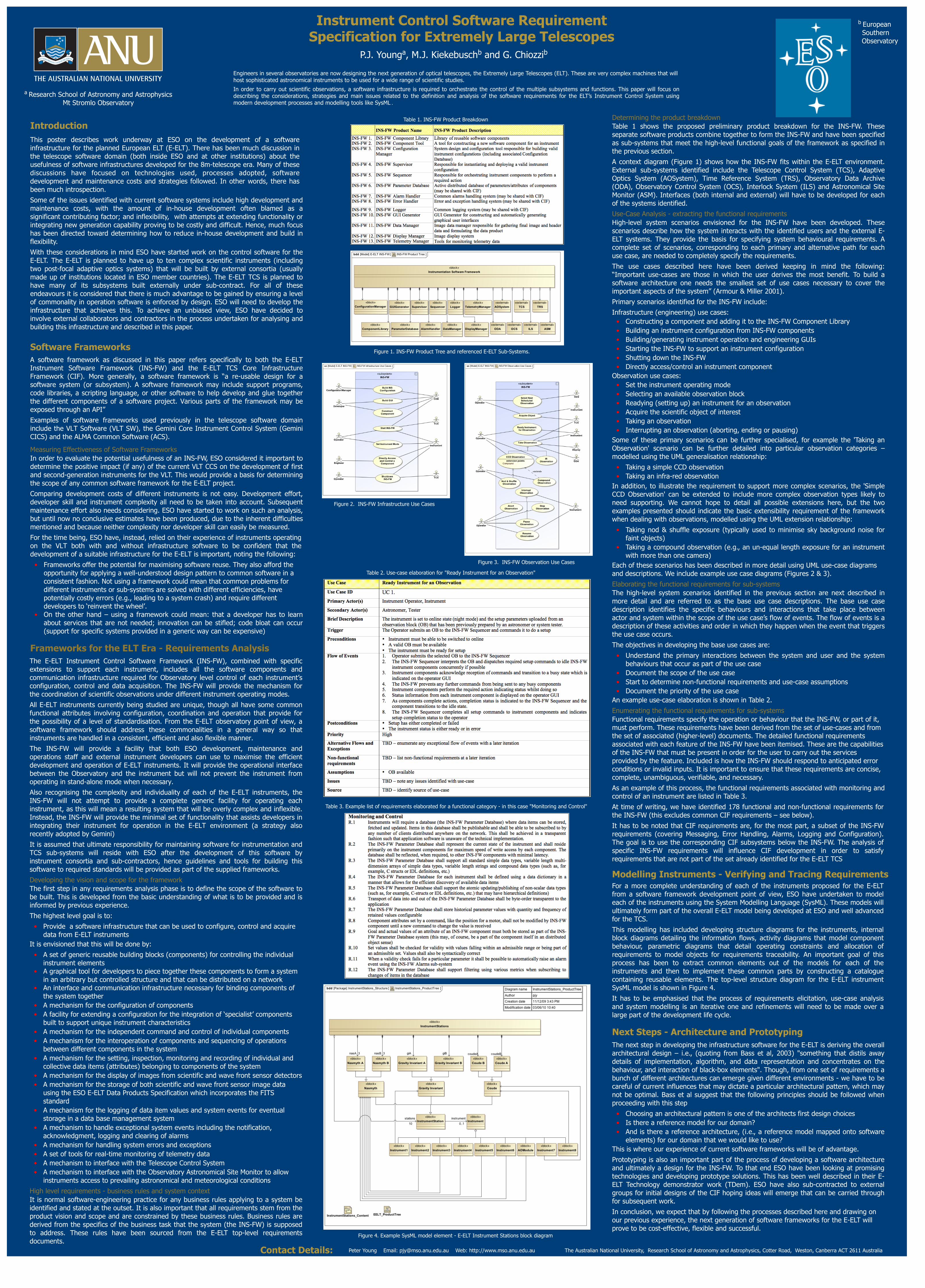
Determining the product breakdownTable 1 shows the proposed preliminary product breakdown for the INS-FW. These separate software products combine together to form the INS-FW and have been specified as sub-systems that meet the high-level functional goals of the framework as specified in the previous section.

A context diagram (Figure 1) shows how the INS-FW fits within the E-ELT environment. External sub-systems identified include the Telescope Control System (TCS), Adaptive Optics System (AOSystem), Time Reference System (TRS), Observatory Data Archive (ODA), Observatory Control System (OCS), Interlock System (ILS) and Astronomical Site Monitor (ASM). Interfaces (both internal and external) will have to be developed for each of the systems identified.

Use-Case Analysis - extracting the functional requirementsHigh-level system scenarios envisioned for the INS-FW have been developed. These scenarios describe how the system interacts with the identified users and the external E-ELT systems. They provide the basis for specifying system behavioural requirements. A complete set of scenarios, corresponding to each primary and alternative path for each use case, are needed to completely specify the requirements.

The use cases described here have been derived keeping in mind the following: “Important use-cases are those in which the user derives the most benefit. To build a software architecture one needs the smallest set of use cases necessary to cover the important aspects of the system” (Armour & Miller 2001).

Primary scenarios identified for the INS-FW include:

Infrastructure (engineering) use cases:• Constructing a component and adding it to the INS-FW Component Library• Building an instrument configuration from INS-FW components• Building/generating instrument operation and engineering GUIs• Starting the INS-FW to support an instrument configuration• Shutting down the INS-FW• Directly access/control an instrument component

Observation use cases:• Set the instrument operating mode• Selecting an available observation block• Readying (setting up) an instrument for an observation• Acquire the scientific object of interest• Taking an observation• Interrupting an observation (aborting, ending or pausing)

Some of these primary scenarios can be further specialised, for example the 'Taking an Observation' scenario can be further detailed into particular observation categories – modelled using the UML generalisation relationship:

• Taking a simple CCD observation• Taking an infra-red observation

In addition, to illustrate the requirement to support more complex scenarios, the 'Simple CCD Observation' can be extended to include more complex observation types likely to need supporting. We cannot hope to detail all possible extensions here, but the two examples presented should indicate the basic extensibility requirement of the framework when dealing with observations, modelled using the UML extension relationship:

• Taking nod & shuffle exposure (typically used to minimise sky background noise for faint objects)

• Taking a compound observation (e.g., an un-equal length exposure for an instrument with more than one camera)

Each of these scenarios has been described in more detail using UML use-case diagrams and descriptions. We include example use case diagrams (Figures 2 & 3).

Elaborating the functional requirements for sub-systemsThe high-level system scenarios identified in the previous section are next described in more detail and are referred to as the base use case descriptions. The base use case description identifies the specific behaviours and interactions that take place between actor and system within the scope of the use case’s flow of events. The flow of events is a description of these activities and order in which they happen when the event that triggers the use case occurs.

The objectives in developing the base use cases are:

• Understand the primary interactions between the system and user and the system behaviours that occur as part of the use case

• Document the scope of the use case• Start to determine non-functional requirements and use-case assumptions• Document the priority of the use case

An example use-case elaboration is shown in Table 2.

Enumerating the functional requirements for sub-systemsFunctional requirements specify the operation or behaviour that the INS-FW, or part of it, must perform. These requirements have been derived from the set of use-cases and from the set of associated (higher-level) documents. The detailed functional requirements associated with each feature of the INS-FW have been itemised. These are the capabilities of the INS-FW that must be present in order for the user to carry out the services provided by the feature. Included is how the INS-FW should respond to anticipated error conditions or invalid inputs. It is important to ensure that these requirements are concise, complete, unambiguous, verifiable, and necessary.

As an example of this process, the functional requirements associated with monitoring and control of an instrument are listed in Table 3.

At time of writing, we have identified 178 functional and non-functional requirements for the INS-FW (this excludes common CIF requirements – see below).

It has to be noted that CIF requirements are, for the most part, a subset of the INS-FW requirements (covering Messaging, Error Handling, Alarms, Logging and Configuration). The goal is to use the corresponding CIF subsystems below the INS-FW. The analysis of specific INS-FW requirements will influence CIF development in order to satisfy requirements that are not part of the set already identified for the E-ELT TCS

For a more complete understanding of each of the instruments proposed for the E-ELT from a software framework development point of view, ESO have undertaken to model each of the instruments using the System Modelling Language (SysML). These models will ultimately form part of the overall E-ELT model being developed at ESO and well advanced for the TCS.

This modelling has included developing structure diagrams for the instruments, internal block diagrams detailing the information flows, activity diagrams that model component behaviour, parametric diagrams that detail operating constraints and allocation of requirements to model objects for requirements traceability. An important goal of this process has been to extract common elements out of the models for each of the instruments and then to implement these common parts by constructing a catalogue containing reusable elements. The top-level structure diagram for the E-ELT instrument SysML model is shown in Figure 4.

It has to be emphasised that the process of requirements elicitation, use-case analysis and system modelling is an iterative one and refinements will need to be made over a large part of the development life cycle.

Modelling Instruments - Verifying and Tracing Requirements

Contact Details: Peter Young Email: [email protected] Web: http://www.mso.anu.edu.au The Australian National University, Research School of Astronomy and Astrophysics, Cotter Road, Weston, Canberra ACT 2611 Australia

The next step in developing the infrastructure software for the E-ELT is deriving the overall architectural design – i.e., (quoting from Bass et al, 2003) "something that distils away details of implementation, algorithm, and data representation and concentrates on the behaviour, and interaction of black-box elements". Though, from one set of requirements a bunch of different architectures can emerge given different environments - we have to be careful of current influences that may dictate a particular architectural pattern, which may not be optimal. Bass et al suggest that the following principles should be followed when proceeding with this step

• Choosing an architectural pattern is one of the architects first design choices• Is there a reference model for our domain?• And is there a reference architecture, (i.e., a reference model mapped onto software

elements) for our domain that we would like to use?This is where our experience of current software frameworks will be of advantage.

Prototyping is also an important part of the process of developing a software architecture and ultimately a design for the INS-FW. To that end ESO have been looking at promising technologies and developing prototype solutions. This has been well described in their E-ELT Technology demonstrator work (TDem). ESO have also sub-contracted to external groups for initial designs of the CIF hoping ideas will emerge that can be carried through for subsequent work.

In conclusion, we expect that by following the processes described here and drawing on our previous experience, the next generation of software frameworks for the E-ELT will prove to be cost-effective, flexible and successful.

Next Steps - Architecture and Prototyping

b European Southern

Observatory

Figure 4. Example SysML model element - E-ELT Instrument Stations block diagram

Figure 1. INS-FW Product Tree and referenced E-ELT Sub-Systems.

Figure 3. INS-FW Observation Use Cases

Figure 2. INS-FW Infrastructure Use Cases

Table 1. INS-FW Product Breakdown

Table 3. Example list of requirements elaborated for a functional category - in this case "Monitoring and Control"

Table 2. Use-case elaboration for "Ready Instrument for an Observation"