Embed Size (px)
Citation preview
2nd Floor Terminal Building A-02/PK Halim Perdana Kusuma International AirportJakarta (13610) INDONESIAPhone : 62-21-808 80028, 62-21-912 600238Fax : 62-21-8097242Website : http://www.indoavis.co.id - www.indoavis.netEmail : [email protected] / [email protected]
PT. INDOAVIS NUSANTARAGeo-informatics and Aeronautical Navigation Services
These charts are for training purposes only
and not to be use for flight
INTRODUCTION TOINDOAVIS
AERONAUTICAL NAVIGATIONCHARTS USER’S GUIDE
INSTRUMENT APPROACH
CHART LEGEND
6
DOC NO: INDOAVIS.UG.0I/III/2009
INTRODUCTION TO INDOAVIS AERONAUTICAL CHART USER’S GUIDE English Version
© INDOAVIS NUSANTARA

PT. INDOAVIS NUSANTARA Geo-informatics and Aeronautical Information Supports.
INSTRUMENT APP. CHART LEGEND [22 Oct 2009] II-10 6.1
5.1 INSTRUMENT APPROACH | INTRODUCTION TO INDOAVIS AERONAUTICAL NAVIGATION CHARTS USERS GUIDE
INSTRUMENT APPROACH CHART LEGEND
FUNCTION This chart shall provide flight crews with information which will enable them to perform an approved instrument approach procedure to the runway of intended landing including the missed approach procedure and where applicable, associated holding patterns.
Note.— Detailed criteria for the establishment of instrument approach procedures and the resolutions of associated altitudes/heights are contained in the Procedures for Air Navigation Services — Aircraft Operations (PANS-OPS,Doc 8168).
Anatomy of Instrument Approaches In Indonesia, instrument approaches are developed by Directorate General of Civil Aviation (DGCA) in accordance with the publication AIP, and are published in the government publication. There are two broad categories of instrument approaches
1) Precision approaches and 2) Non-precision approaches.
The Four Instrument Approach Segments

PT. INDOAVIS NUSANTARA Geo-informatics and Aeronautical Information Supports.
INSTRUMENT APP. CHART LEGEND [22 Oct 2009] II-10 6.2
5.2 INSTRUMENT APPROACH | INTRODUCTION TO INDOAVIS AERONAUTICAL NAVIGATION CHARTS USERS GUIDE
GENERAL CHART FORMAT The four step of Indoavis chart layout

PT. INDOAVIS NUSANTARA Geo-informatics and Aeronautical Information Supports.
INSTRUMENT APP. CHART LEGEND [22 Oct 2009] II-10 6.3
5.3 INSTRUMENT APPROACH | INTRODUCTION TO INDOAVIS AERONAUTICAL NAVIGATION CHARTS USERS GUIDE
H E A D I N G
OVERVIEW OF HEADING FEATURES
1) ICAO Airport code identifier 2) IATA Airport code identifier 3) Airport name 4) AIRAC Date publication 5) Index number, Chart are sequenced by type 6) Chart color code, Individual INDOAVIS charts are identified on both the top color of the
page by their procedure name (based on the NAVAIDs (Green is NDB, Blue is VOR or VOR/DME, ILS is Magenta and brown is GPS/GNSS)
7) Location City-Country name 8) Procedure Identification 9) Communication frequencies, Pilots typically refer to the next rows from top to bottom to
set up and brief the approach. The communications section of the format is arranged horizontally in the top row.
a. ATIS : ATIS Arrival Frequency b. DIRECTOR : Director Call and Frequency c. APPROACH : Approach Control Call and Frequency d. (R) : Radar available e. TOWER : Tower Call and Frequency f. GROUND : Ground Call and Frequency
10) Missed Approach instruction 11) Notes application to the approach procedure. 12) Aerodrome Elevation 13) Transition Level (FL) (QNE) and Transition Altitude (FT) (QNH), Transition Level and
Transition Altitude are provided for all areas in Indonesia. 14) Minimum Safe altitude (MSA) Altitudes are protected to a 25 Nautical mile radius unless
special otherwise. Altitude depicted on (IAP, SID and STAR Chart) and identified as the minimum altitude which provide a 1.000ft obstacle clearance
a. Arrows on distance circle identify sector b. Facility identifier

PT. INDOAVIS NUSANTARA Geo-informatics and Aeronautical Information Supports.
INSTRUMENT APP. CHART LEGEND [22 Oct 2009] II-10 6.4
5.4 INSTRUMENT APPROACH | INTRODUCTION TO INDOAVIS AERONAUTICAL NAVIGATION CHARTS USERS GUIDE
PLAN VIEW Briefing Sequence
OVERVIEW OF HEADING FEATURES
1) Scale Bar (inch / kilometers to Nautical miles)
2) Entry holding with fix point, altitude and time
3) Highest reference point with the plan view show in box
4) Drainage River and water features
5) Holding pattern, Holding pattern not part of the approach procedure.
6) Final approach course bearing is enlarged and made bold.
7) Primary navaid information enlarged and made bold and bold type and a shadow box for easy recognition.
8) Secondary navaid information
9) Missed approach track
10) Nearby Civil or joint Military airport
11) Airport
12) Restricted airspace The accompanying label indicated it as prohibited, restricted, danger, etc

PT. INDOAVIS NUSANTARA Geo-informatics and Aeronautical Information Supports.
INSTRUMENT APP. CHART LEGEND [22 Oct 2009] II-10 6.5
5.5 INSTRUMENT APPROACH | INTRODUCTION TO INDOAVIS AERONAUTICAL NAVIGATION CHARTS USERS GUIDE
APPROACH CHART LEGEND PLAN VIEW SYMBOLS
1. PROCEDURE TRACKS
Approach procedure track
Missed approach procedure track
Holding track including bearing direction value.
2. BEARING TRACKS
Magnetic course
True course
Magnetic heading
Magnetic radial
3. RADIO NAVIGATION AIDS
LOC/LDA/SDF/MLS
Transmitter (Shown when installation is offset from its normal position off the end of the runway)
LOC/DME Collocated LOC and DME radio navigation aids
VOR VHF omnidirectional radio range
NDB Non-directional radio beacon
TACAN
UHF tactical air navigation aid
DME Distance measuring equipment
VOR/DME
Collocated VOR and DME radio navigation aids
VORTAC
Collocated VOR and TACAN radio navigation aids
ILS Instrument landing system
ILS, LOC. LDA, SDF, MLS or KRM
LOC
Elliptical Radio marker beacon
MM (Middle Marker) OM (Outer Marker
Bone Shape
Compass rose
4. Compass rose To be orientated on the chart in accordance with the alignment of the station (normally Magnetic North),
5. Compass rose to be used as appropriate in combination with the following symbols: (VOR, VOR/DME, TACAN, VORTAC)
PT. INDOAVIS NUSANTARA Geo-informatics and Aeronautical Information Supports.
INSTRUMENT APP. CHART LEGEND [22 Oct 2009] II-10 6.6
5.6 INSTRUMENT APPROACH | INTRODUCTION TO INDOAVIS AERONAUTICAL NAVIGATION CHARTS USERS GUIDE
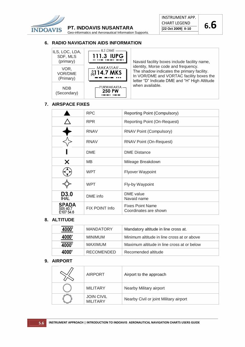
6. RADIO NAVIGATION AIDS INFORMATION
ILS, LOC, LDA, SDF, MLS (primary)
Navaid facility boxes include facility name, identity, Morse code and frequency. The shadow indicates the primary facility. In VOR/DME and VORTAC facility boxes the letter “D” Indicate DME and “H” High Altitude when available.
VOR, VOR/DME (Primary)
NDB (Secondary)
7. AIRSPACE FIXES
RPC Reporting Point (Compulsory)
RPR Reporting Point (On-Request)
RNAV RNAV Point (Compulsory)
RNAV RNAV Point (On-Request)
DME DME Distance
MB Mileage Breakdown
WPT Flyover Waypoint
WPT Fly-by Waypoint
DME info
DME value Navaid name
FIX POINT Info
Fixes Point Name Coordinates are shown
8. ALTITUDE
MANDATORY Mandatory altitude in line cross at.
MINIMUM Minimum altitude in line cross at or above
MAXIMUM Maximum altitude in line cross at or below
RECOMENDED Recomended altitude
9. AIRPORT
AIRPORT Airport to the approach
MILITARY Nearby Military airport
JOIN CIVIL MILITARY
Nearby Civil or joint Military airport

PT. INDOAVIS NUSANTARA Geo-informatics and Aeronautical Information Supports.
INSTRUMENT APP. CHART LEGEND [22 Oct 2009] II-10 6.7
5.7 INSTRUMENT APPROACH | INTRODUCTION TO INDOAVIS AERONAUTICAL NAVIGATION CHARTS USERS GUIDE
HELIPORT
Heli Landing site A white letter H indicates an area reserved for take-off and landing helicopters.
SEAPLANE Military and Civil Seaplane Base
10. OBSTACLE
10.1 MAN-MADE STRUCTURES
Tower Unlighted Man-made structure.
Tower Lighted Man-made structure.
Obstacle Structure
Unidentified man-made structure
10.2 TERRAIN HIGH POINTS
Spot Elevation
Mean Sea Level (MSL) elevation at top of terrain high point/man-made structure.
Spot Elevation unsurveyed accuracy
Spot highest elevation
Box indicates only the highest of portrayed terrain high point and man-made structures may exist which have not been portrayed.
Generalized terrain contour information. The Gradient tints indicate the elevation change between contour intervals
11. RESTRICTED AIRSPACE
Restricted airspace. The accompanying label indicates it as prohibited, restricted, danger, etc. (T) Training, (A) Alert, (C) Caution, and Military Operations Areas.
WI Country identifier
WI : Indonesia, WS : Singapore WM : Malaysia YB : Australia (R) Restricted ________ 121 designation number UNL Unlimited (Upper Limit) GND Ground (Lower Limit) 0800-2200 Hours active MON-SAT Day active IND-ARTC Controling Agency
(A) Alert (T) Training (C) Caution (W) Warning (D) Danger (P) Prohibited (R) Restricted (TRA) Temporary Reserved Airspace (TSA) Temporary Segregated Area
(MOA) Military Operations Area

PT. INDOAVIS NUSANTARA Geo-informatics and Aeronautical Information Supports.
INSTRUMENT APP. CHART LEGEND [22 Oct 2009] II-10 6.8
5.8 INSTRUMENT APPROACH | INTRODUCTION TO INDOAVIS AERONAUTICAL NAVIGATION CHARTS USERS GUIDE
12. MAGNETIC BEARING
Bearing magnetic variation Magnetic declination is the angle between magnetic north (the direction the north end of a compass needle points) and true north. The declination is positive when the magnetic north is east of true north. The term magnetic variation is a synonym
13. HOLDING ENTRY
Type entry holding
Notes :
Holding Patterns are generally not charted to scale
Holding Pattern not part of the approach procedure.
14. ORIENTATION DETAIL
Lake or large water areas
River
APPROACH CHART LEGEND PROFILE VIEW
PRECISION APPROACH PROFILE (ILS with LOC (GP out), or with NDB Approach
Type procedure for Precision approaches systems
ILS Instrument Landing System
MLS Microwave Landing System
PAR Precision Approach Radar (Military)
GPS (with vertical navigation via WAAS or EGNOS) - Global Positioning System
LAAS Ground Based Augmentation System (GBAS) for (GNSS)
JPALS Joint Precision Approach and Landing System
GCA Ground-Controlled Approach (mostly military)

PT. INDOAVIS NUSANTARA Geo-informatics and Aeronautical Information Supports.
INSTRUMENT APP. CHART LEGEND [22 Oct 2009] II-10 6.9
5.9 INSTRUMENT APPROACH | INTRODUCTION TO INDOAVIS AERONAUTICAL NAVIGATION CHARTS USERS GUIDE
NON - PRECISION APPROACH PROFILE (LOC, VOR, VORTAC, NDB)
Type of Non-precision approaches systems
Localizer (LOC)
VOR / VORDME
NDB, Non-Directional Beacon
Localizer Type Directional Aid or LDA
Simplified Directional Facility or SDF
GPS - Global Positioning System
TACAN
SRA - Surveillance Radar Approach
NON - PRECISION APPROACH PROFILE (VISUAL APPROACH)

PT. INDOAVIS NUSANTARA Geo-informatics and Aeronautical Information Supports.
INSTRUMENT APP. CHART LEGEND [22 Oct 2009] II-10 6.10
5.10 INSTRUMENT APPROACH | INTRODUCTION TO INDOAVIS AERONAUTICAL NAVIGATION CHARTS USERS GUIDE
APPROACH CHART LEGEND PROFILE SYMBOLS
1. MARKER BAECON
Radio navigation aid (type of aid and its use in the procedure to be annotated on top of the symbol)
Radio marker beacon (type of beacon to be annotated on top of the symbol)
DME fix (distance from DME and the fix use in the procedure to be annotated on bottom of the symbol)
Collocated DME fix and marker beacon (distance from DME and the type of beacon to be annotated on top of the symbol)
2. TRACK SYMBOL
Approach procedure flight track
Visual procedure flight track
Missed approach track
Distance fixed
Missed approach fix
Airport profile
Final Approach Fix (FAP) (for non-precision approaches)
Visual Descent Point (VDP)
Racetrack used in lieu of procedure turn with holding limit, outbound and inbound bearing.

PT. INDOAVIS NUSANTARA Geo-informatics and Aeronautical Information Supports.
INSTRUMENT APP. CHART LEGEND [22 Oct 2009] II-10 6.11
5.11 INSTRUMENT APPROACH | INTRODUCTION TO INDOAVIS AERONAUTICAL NAVIGATION CHARTS USERS GUIDE
APPROACH CHART LEGEND LANDING MINIMUMS
PRECISION APPROACH PROFILE (ILS with LOC / GP out)
NON - PRECISION APPROACH PROFILE (LOC, VOR, VORTAC, NDB)
* Maximum speed for reversal and racetrack procedures. Vat - Speed at threshold base on 1.3 time stall speed Vso or 1.23 time stall speed Vs1g in the landing confoguration maxximum certificated landing mass.

PT. INDOAVIS NUSANTARA Geo-informatics and Aeronautical Information Supports.
INSTRUMENT APP. CHART LEGEND [22 Oct 2009] II-10 6.12
5.12 INSTRUMENT APPROACH | INTRODUCTION TO INDOAVIS AERONAUTICAL NAVIGATION CHARTS USERS GUIDE
RVR (RUNWAY VISUAL RANGE)
RVR (Metres)
RVR (Feet)
Visibility (Miles)
Comparable Values of RVR and Visibility
400 800
1000 1200 1400 1600 2000
1600 2400 3200 4000 4500 5000 6000
¼ 1/2 5/8 3/4 7/8 1
1 1/4
The following table shall be used for converting RVR to ground or flight visibility. For converting RVR values that fall between listed, use the next higher RVR value: do not interpolate. For example, when converting 1800 RVR, use 2400 RVR with the resultant visibility of 1/2 mile.
APPROACH LIGHTING SYSTEM
HIAL CAT-1 High Intensity Approach Lighting Category-1
HIAL CAT-2 High Intensity Approach Lighting Category -2
SHIAL Simple High Intensity Approach Lighting
LIAL Low Intensity Approach Lighting
For a 3.00° glideslope the nominal eye height over the runway threshold is 49’ (15m) Fan increase in eye height over the runway threshold is required to provide adequate wheel clearance, then the approach nay be flown with one more fly down lights visible.
PAPI Precision Approach Path Indicator
PAPI is normally installed on the LEFT side of the runway
T-VASI
Visual Approach Slope Indicator
VASI is normally installed on the LEFT side of the runway. VASI may be installed on the RIGHT side or BOTH sides of the runway
TDZL Runway touchdown Zone
CL Runway centerline light

PT. INDOAVIS NUSANTARA Geo-informatics and Aeronautical Information Supports.
INSTRUMENT APP. CHART LEGEND [22 Oct 2009] II-10 6.13
5.13 INSTRUMENT APPROACH | INTRODUCTION TO INDOAVIS AERONAUTICAL NAVIGATION CHARTS USERS GUIDE
INSTRUMENT APPROACH CHART
ILS RWY-25 PROCEDURE
WBGG- KUCHING, MALAYSIA
SAMPLE ONLY NOT FOR NAVIGATION USE.!

PT. INDOAVIS NUSANTARA Geo-informatics and Aeronautical Information Supports.
INSTRUMENT APP. CHART LEGEND [22 Oct 2009] II-10 6.14
5.14 INSTRUMENT APPROACH | INTRODUCTION TO INDOAVIS AERONAUTICAL NAVIGATION CHARTS USERS GUIDE
INSTRUMENT APPROACH CHART
VOR/DME RWY-29 PROCEDURE
WICC - BANDUNG, INDONESIA
SAMPLE ONLY NOT FOR NAVIGATION USE.!

PT. INDOAVIS NUSANTARA Geo-informatics and Aeronautical Information Supports.
INSTRUMENT APP. CHART LEGEND [22 Oct 2009] II-10 6.15
5.15 INSTRUMENT APPROACH | INTRODUCTION TO INDOAVIS AERONAUTICAL NAVIGATION CHARTS USERS GUIDE
INSTRUMENT APPROACH CHART
NDB RWY-36 PROCEDURE
WAMM- MANADO, INDONESIA
SAMPLE ONLY NOT FOR NAVIGATION USE.!


![VFR AERONAUTICAL NAVIGATION CHART LEGEND AE… · AERONAUTICAL PT. INDOAVIS NUSANTARA Geo-informatics and Aeronautical Information Services. CHART LEGEND [25 Oct 2009] II-10 4.1 4.1](https://img.dokumen.tips/doc/110x75/60bd09c472c56d5ffc214633/vfr-aeronautical-navigation-chart-legend-ae-aeronautical-pt-indoavis-nusantara.jpg)