Embed Size (px)
Citation preview

Instructions for use
Infinity Acute Care System
Babylog VN500Ventilation unitSW 2.n
WARNING To properly use this medical device, read and comply with these instructions for use.

2 Instructions for use Infinity Acute Care System – Babylog VN500 SW 2.n
Typographical conventions
Any text shown on the screen and any labeling on the device are printed in bold and italics, for example, PEEP, Air or Alarms.
The "greater than" symbol > indicates the navigation path in a dialog window, for example, System setup > Ventilation > Modes.
In this example, System setup represents the dialog window title, Ventilation represents a horizontally aligned tab, and Modes a vertically aligned tab.
Screen images
Schematic renderings of screen images are used, which may differ in appearance or in configuration from the actual screen images.
Use of terms
Dräger uses the term "Accessory" not only for accessories in the context of IEC 60601-1, but also for consumable parts, removable parts, and attached parts.
Trademarks
1 Consecutive numbers indicate steps of action, with the numbering restarting with "1" for each new sequence of actions.
Bullet points indicate individual actions or different options for action.
– Dashes indicate the listing of data, options, or objects.
(A) Letters in parentheses refer to elements in the related illustration.
A Letters in illustrations denote elements referred to in the text.
Trademark Trademark owner
Babylog® Dräger
Infinity®
QuickSet®
ATC®
Acute Care System®
Medical CockpitTM
DrägerService®
MEDIBUS™
MEDIBUS.X®
Sekusept® Ecolab
Actichlor®
Oxycide® Ecolab USA
Klorsept® Medentech
BruTab 6S® Brulin
Descogen® Antiseptica
Dismozon® BODE Chemie
Mikrobac®
Virkon® DuPont
Perform® Schülke & Mayr
Mikrozid®
Buraton®
Trademark Trademark owner
Instructions for use Infinity Acute Care System – Babylog VN500 SW 2.n 3
Safety information definitions
Definition of the target groups
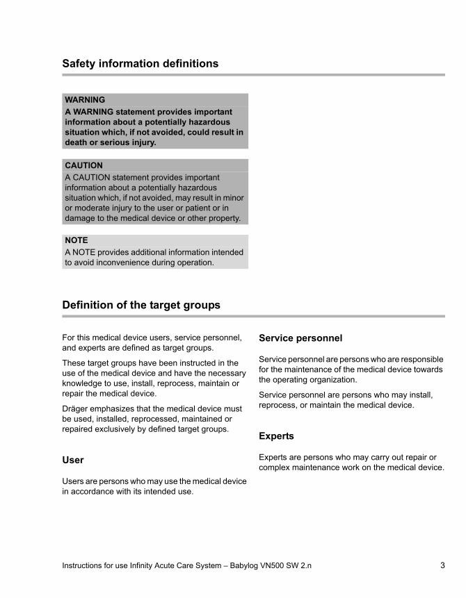
For this medical device users, service personnel, and experts are defined as target groups.
These target groups have been instructed in the use of the medical device and have the necessary knowledge to use, install, reprocess, maintain or repair the medical device.
Dräger emphasizes that the medical device must be used, installed, reprocessed, maintained or repaired exclusively by defined target groups.
User
Users are persons who may use the medical device in accordance with its intended use.
Service personnel
Service personnel are persons who are responsible for the maintenance of the medical device towards the operating organization.
Service personnel are persons who may install, reprocess, or maintain the medical device.
Experts
Experts are persons who may carry out repair or complex maintenance work on the medical device.
WARNING
A WARNING statement provides important information about a potentially hazardous situation which, if not avoided, could result in death or serious injury.
CAUTION
A CAUTION statement provides important information about a potentially hazardous situation which, if not avoided, may result in minor or moderate injury to the user or patient or in damage to the medical device or other property.
NOTE
A NOTE provides additional information intended to avoid inconvenience during operation.

4 Instructions for use Infinity Acute Care System – Babylog VN500 SW 2.n
Abbreviations and symbols
For explanations refer to sections "Abbreviations" and "Symbols" in chapter "System overview".

Instructions for use Infinity Acute Care System – Babylog VN500 SW 2.n 5
Contents
Contents
Typographical conventions. . . . . . . . . . . . . . . . 2Trademarks . . . . . . . . . . . . . . . . . . . . . . . . . . . 2Safety information definitions . . . . . . . . . . . . . . 3Definition of the target groups . . . . . . . . . . . . . 3Abbreviations and symbols. . . . . . . . . . . . . . . . 4
For your safety and that of your patients. . . 7
General safety information . . . . . . . . . . . . . . . . 8Product-specific safety information. . . . . . . . . . 12
Application . . . . . . . . . . . . . . . . . . . . . . . . . . . 17
Intended use. . . . . . . . . . . . . . . . . . . . . . . . . . . 18Indications for use and contraindications . . . . . 18Environment of use. . . . . . . . . . . . . . . . . . . . . . 18
System overview . . . . . . . . . . . . . . . . . . . . . . 19
Infinity Acute Care System – Workstation Neonatal Care . . . . . . . . . . . . . . . . . . . . . . . . . 20Babylog VN500 ventilation unit. . . . . . . . . . . . . 21Trolley 2 - 90 cm . . . . . . . . . . . . . . . . . . . . . . . 23GS500 gas supply unit . . . . . . . . . . . . . . . . . . 24Range of functions . . . . . . . . . . . . . . . . . . . . . . 25Abbreviations . . . . . . . . . . . . . . . . . . . . . . . . . . 27Symbols . . . . . . . . . . . . . . . . . . . . . . . . . . . . . . 32
Operating concept . . . . . . . . . . . . . . . . . . . . . 35
Operating concept for Infinity C500 . . . . . . . . . 36Operating concept for Babylog VN500 . . . . . . 36
Assembly and preparation . . . . . . . . . . . . . . 41
Safety information for assembly and preparation . . . . . . . . . . . . . . . . . . . . . . . . . . . . 42Preparing the trolley . . . . . . . . . . . . . . . . . . . . 42Preparing the Medical Cockpit . . . . . . . . . . . . . 46Preparing the ventilation unit . . . . . . . . . . . . . . 50Intrahospital transport. . . . . . . . . . . . . . . . . . . . 62
Getting started . . . . . . . . . . . . . . . . . . . . . . . . 63
Safety information on getting started . . . . . . . . 64Switching on Babylog VN500 and Infinity C500 . . . . . . . . . . . . . . . . . . . . . . . . . . . 64Selecting a patient . . . . . . . . . . . . . . . . . . . . . . 65
Selecting the breathing circuit and the breathing gas humidifier . . . . . . . . . . . . . . . . . 68Checking readiness for operation . . . . . . . . . . 70Selecting the Tube or NIV application mode . 78Selecting the therapy type . . . . . . . . . . . . . . . 79Starting therapy . . . . . . . . . . . . . . . . . . . . . . . . 80Displaying the status of accessories . . . . . . . . 81
Operation . . . . . . . . . . . . . . . . . . . . . . . . . . . 83
Setting ventilation . . . . . . . . . . . . . . . . . . . . . . 84NIV – Non-invasive ventilation . . . . . . . . . . . . 92Displaying curves and measured values . . . . 95Help . . . . . . . . . . . . . . . . . . . . . . . . . . . . . . . . 99Maneuvers. . . . . . . . . . . . . . . . . . . . . . . . . . . . 100Medication nebulization . . . . . . . . . . . . . . . . . 103GS500 gas supply unit . . . . . . . . . . . . . . . . . . 110O2 therapy . . . . . . . . . . . . . . . . . . . . . . . . . . . 111Standby mode . . . . . . . . . . . . . . . . . . . . . . . . . 114Ending operation . . . . . . . . . . . . . . . . . . . . . . . 116Disconnecting the device from the mains voltage. . . . . . . . . . . . . . . . . . . . . . . . . . . . . . . 117Storing Babylog VN500 . . . . . . . . . . . . . . . . . . 117Mains power supply / DC power supply . . . . . 118Intrahospital patient transport . . . . . . . . . . . . . 121
Alarms . . . . . . . . . . . . . . . . . . . . . . . . . . . . . . 123
Overview . . . . . . . . . . . . . . . . . . . . . . . . . . . . . 124Display of alarms. . . . . . . . . . . . . . . . . . . . . . . 124Displaying information on alarms . . . . . . . . . . 126Alarm history . . . . . . . . . . . . . . . . . . . . . . . . . . 127Setting alarm limits . . . . . . . . . . . . . . . . . . . . . 128Setting the volume of the alarm tone . . . . . . . 130Suppressing the alarm tone . . . . . . . . . . . . . . 131Position of the user to the alarm system . . . . . 131Failure of the acoustic alarm . . . . . . . . . . . . . 132
Trends and data . . . . . . . . . . . . . . . . . . . . . . . 133
Overview . . . . . . . . . . . . . . . . . . . . . . . . . . . . . 134Displaying trends . . . . . . . . . . . . . . . . . . . . . . 134Displaying data . . . . . . . . . . . . . . . . . . . . . . . . 138Displaying the logbook . . . . . . . . . . . . . . . . . . 139Data export . . . . . . . . . . . . . . . . . . . . . . . . . . . 140
Contents
6 Instructions for use Infinity Acute Care System – Babylog VN500 SW 2.n
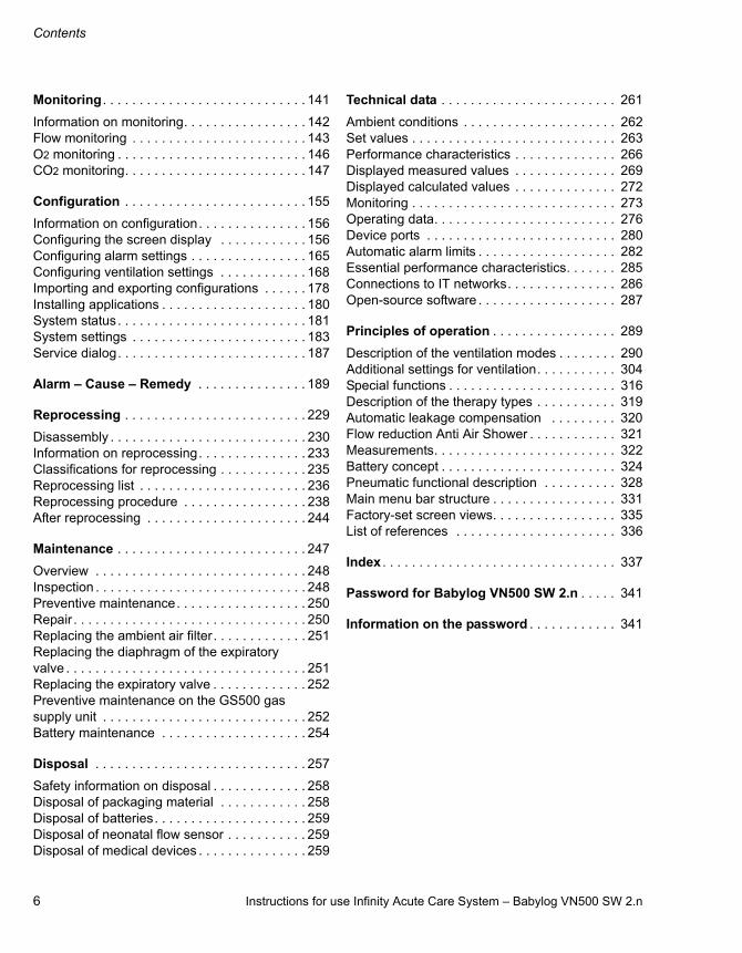
Monitoring . . . . . . . . . . . . . . . . . . . . . . . . . . . . 141
Information on monitoring. . . . . . . . . . . . . . . . . 142Flow monitoring . . . . . . . . . . . . . . . . . . . . . . . . 143O2 monitoring . . . . . . . . . . . . . . . . . . . . . . . . . . 146CO2 monitoring. . . . . . . . . . . . . . . . . . . . . . . . . 147
Configuration . . . . . . . . . . . . . . . . . . . . . . . . . 155
Information on configuration. . . . . . . . . . . . . . . 156Configuring the screen display . . . . . . . . . . . . 156Configuring alarm settings . . . . . . . . . . . . . . . . 165Configuring ventilation settings . . . . . . . . . . . . 168Importing and exporting configurations . . . . . . 178Installing applications . . . . . . . . . . . . . . . . . . . . 180System status. . . . . . . . . . . . . . . . . . . . . . . . . . 181System settings . . . . . . . . . . . . . . . . . . . . . . . . 183Service dialog. . . . . . . . . . . . . . . . . . . . . . . . . . 187
Alarm – Cause – Remedy . . . . . . . . . . . . . . . 189
Reprocessing . . . . . . . . . . . . . . . . . . . . . . . . . 229
Disassembly . . . . . . . . . . . . . . . . . . . . . . . . . . . 230Information on reprocessing. . . . . . . . . . . . . . . 233Classifications for reprocessing . . . . . . . . . . . . 235Reprocessing list . . . . . . . . . . . . . . . . . . . . . . . 236Reprocessing procedure . . . . . . . . . . . . . . . . . 238After reprocessing . . . . . . . . . . . . . . . . . . . . . . 244
Maintenance . . . . . . . . . . . . . . . . . . . . . . . . . . 247
Overview . . . . . . . . . . . . . . . . . . . . . . . . . . . . . 248Inspection . . . . . . . . . . . . . . . . . . . . . . . . . . . . . 248Preventive maintenance. . . . . . . . . . . . . . . . . . 250Repair . . . . . . . . . . . . . . . . . . . . . . . . . . . . . . . . 250Replacing the ambient air filter. . . . . . . . . . . . . 251Replacing the diaphragm of the expiratory valve . . . . . . . . . . . . . . . . . . . . . . . . . . . . . . . . . 251Replacing the expiratory valve . . . . . . . . . . . . . 252Preventive maintenance on the GS500 gas supply unit . . . . . . . . . . . . . . . . . . . . . . . . . . . . 252Battery maintenance . . . . . . . . . . . . . . . . . . . . 254
Disposal . . . . . . . . . . . . . . . . . . . . . . . . . . . . . 257
Safety information on disposal . . . . . . . . . . . . . 258Disposal of packaging material . . . . . . . . . . . . 258Disposal of batteries. . . . . . . . . . . . . . . . . . . . . 259Disposal of neonatal flow sensor . . . . . . . . . . . 259Disposal of medical devices . . . . . . . . . . . . . . . 259
Technical data . . . . . . . . . . . . . . . . . . . . . . . . 261
Ambient conditions . . . . . . . . . . . . . . . . . . . . . 262Set values . . . . . . . . . . . . . . . . . . . . . . . . . . . . 263Performance characteristics . . . . . . . . . . . . . . 266Displayed measured values . . . . . . . . . . . . . . 269Displayed calculated values . . . . . . . . . . . . . . 272Monitoring . . . . . . . . . . . . . . . . . . . . . . . . . . . . 273Operating data. . . . . . . . . . . . . . . . . . . . . . . . . 276Device ports . . . . . . . . . . . . . . . . . . . . . . . . . . 280Automatic alarm limits . . . . . . . . . . . . . . . . . . . 282Essential performance characteristics. . . . . . . 285Connections to IT networks. . . . . . . . . . . . . . . 286Open-source software . . . . . . . . . . . . . . . . . . . 287
Principles of operation . . . . . . . . . . . . . . . . . 289
Description of the ventilation modes . . . . . . . . 290Additional settings for ventilation. . . . . . . . . . . 304Special functions . . . . . . . . . . . . . . . . . . . . . . . 316Description of the therapy types . . . . . . . . . . . 319Automatic leakage compensation . . . . . . . . . 320Flow reduction Anti Air Shower . . . . . . . . . . . . 321Measurements. . . . . . . . . . . . . . . . . . . . . . . . . 322Battery concept . . . . . . . . . . . . . . . . . . . . . . . . 324Pneumatic functional description . . . . . . . . . . 328Main menu bar structure . . . . . . . . . . . . . . . . . 331Factory-set screen views. . . . . . . . . . . . . . . . . 335List of references . . . . . . . . . . . . . . . . . . . . . . 336
Index . . . . . . . . . . . . . . . . . . . . . . . . . . . . . . . . 337
Password for Babylog VN500 SW 2.n . . . . . 341
Information on the password . . . . . . . . . . . . 341

Instructions for use Infinity Acute Care System – Babylog VN500 SW 2.n 7
For your safety and that of your patients
For your safety and that of your patients
General safety information . . . . . . . . . . . . . . 8
Strictly follow these instructions for use . . . . . . 8Maintenance. . . . . . . . . . . . . . . . . . . . . . . . . . . 8Safety checks . . . . . . . . . . . . . . . . . . . . . . . . . . 8Accessories . . . . . . . . . . . . . . . . . . . . . . . . . . . 8Not for use in areas of explosion hazard . . . . . 9Safe connection to other electrical equipment. . . . . . . . . . . . . . . . . . . . . . . . . . . . . 9Connected devices. . . . . . . . . . . . . . . . . . . . . . 9Device combinations . . . . . . . . . . . . . . . . . . . . 9Connection to IT network . . . . . . . . . . . . . . . . . 10Patient safety . . . . . . . . . . . . . . . . . . . . . . . . . . 10Patient monitoring. . . . . . . . . . . . . . . . . . . . . . . 10Information on electromagnetic compatibility . . 11Disposable articles . . . . . . . . . . . . . . . . . . . . . . 11Sterile accessories . . . . . . . . . . . . . . . . . . . . . . 11Installing accessories . . . . . . . . . . . . . . . . . . . . 11Storing the instructions for use . . . . . . . . . . . . . 11Training. . . . . . . . . . . . . . . . . . . . . . . . . . . . . . . 11
Product-specific safety information . . . . . . . 12
Monitoring ventilation . . . . . . . . . . . . . . . . . . . . 14Back-up ventilation with an independent manual ventilation device . . . . . . . . . . . . . . . . . 14Handling Infinity ID components. . . . . . . . . . . . 15

For your safety and that of your patients
8 Instructions for use Infinity Acute Care System – Babylog VN500 SW 2.n
General safety information
The following WARNING and CAUTION statements apply to general operation of the medical device. WARNING and CAUTION statements specific to subsystems or particular features of the medical device appear in the respective sections of these instructions for use or in the instructions for use of another product being used with this device.
Strictly follow these instructions for use
Maintenance
Safety checks
The medical device must be subject to regular safety checks. See chapter "Maintenance".
Accessories
WARNING
Any use of the medical device requires full understanding and strict observation of all sections of these instructions for use. The medical device must only be used for the purpose specified under "Intended use" on page 18 and in conjunction with appropriate patient monitoring (see page 10). Strictly observe all WARNING and CAUTION statements throughout these instructions for use and all statements on medical device labels. Failure to observe these safety information statements constitutes a use of the medical device that is inconsistent with its intended use.
WARNING
The medical device must be inspected and serviced regularly by service personnel. Repairs or complex maintenance work carried out on the medical device must be performed by experts.Dräger recommends that a service contract is taken out with DrägerService and that all repairs are performed by DrägerService. Dräger recommends that only genuine Dräger parts are used for maintenance. If the above are not complied with, the correct functioning of the medical device may be compromised. Observe chapter "Maintenance".
WARNING
Only the accessories shown in the list of accessories 9039002 (2nd edition or later) have been tested and approved for use with the medical device. Therefore, it is strongly recommended that only these accessories are used in conjunction with the medical device. Otherwise, the correct functioning of the medical device may be compromised.
Instructions for use Infinity Acute Care System – Babylog VN500 SW 2.n 9
For your safety and that of your patients
Not for use in areas of explosion hazard
Safe connection to other electrical equipment
Connected devices
Device combinations
This device can be operated in combination with other Dräger devices or with devices from other manufacturers. Observe the accompanying documents of the individual devices.
If a device combination is not approved by Dräger, the safety and the correct functioning of the individual devices can be compromised. The operating organization must ensure that the device combination complies with the applicable editions of the relevant standards for medical devices.
Device combinations approved by Dräger meet the requirements of the following standards:– IEC˽60601-1, 3rd˽edition (general
requirements for safety, device combinations, software-controlled functions)– IEC˽60601-1-2 (electromagnetic
compatibility)– IEC˽60601-1-8 (alarm systems)
Or:– IEC˽60601-1, 2nd˽edition (general
requirements for safety)– IEC˽60601-1-1 (device combinations)– IEC˽60601-1-2 (electromagnetic
compatibility)– IEC˽60601-1-4 (software-controlled
functions)– IEC˽60601-1-8 (alarm systems)
WARNING
This medical device is neither approved nor certified for use in areas where combustible or explosive gas mixtures are likely to occur.
WARNING
Risk of patient injury
Electrical connections to equipment not listed in these instructions for use or these assembly instructions must only be made when approved by each respective manufacturer.
WARNING
Risk of electric shock and of device malfunction
Any connected devices or device combinations not complying with the requirements mentioned in these instructions for use may compromise the correct functioning of the medical device. Before operating the medical device, strictly comply with the instructions for use of all connected devices or device combinations.

For your safety and that of your patients
10 Instructions for use Infinity Acute Care System – Babylog VN500 SW 2.n
Connection to IT network
The connection of the medical device to a network or later changes in the network can result in previously unidentified risks for patients, users and third parties. These risks must be identified and controlled before putting the medical device into operation.Relevant changes to the network include:– Configuration changes– Adding or removing additional equipment– Update or upgrade of connected devices
Risks
Overloading of the medical device as a result of very high network traffic (e.g., due to "denial of service" attacks) could lead to deactivation of the interfaces. The service functionality would not then be available until the medical device has been restarted. In rare cases, a warm boot may take place and may occur repeatedly.
Patient safety
The design of the medical device, the accompanying documentation, and the labeling on the medical device are based on the assumption that the purchase and the use of the medical device are restricted to persons familiar with the most important inherent characteristics of the medical device. Instructions and WARNING and CAUTION statements are therefore largely limited to the specifics of the Dräger medical device.These instructions for use do not contain references to various hazards which are obvious to users or references to the consequences of medical device misuse, or to potentially adverse effects in patients with different underlying diseases. Medical device modification or misuse can be dangerous.
Patient monitoring
The user of the medical device is responsible for choosing suitable monitoring that provides appropriate information about medical device performance and the patient's condition.
Patient safety may be achieved by a wide variety of means ranging from electronic surveillance of medical device performance and patient condition to simple, direct observation of clinical signs.
The responsibility for selecting the best level of patient monitoring lies solely with the user of the medical device.
CAUTION
Risk of patient injury
Do not make therapeutic decisions based solely on individual measured values and monitoring parameters.
Instructions for use Infinity Acute Care System – Babylog VN500 SW 2.n 11
For your safety and that of your patients
Information on electromagnetic compatibility
General information on electromagnetic compatibility (EMC) according to international EMC standard IEC 60601-1-2:
Electromedical devices are subject to special precautionary measures concerning electromagnetic compatibility (EMC) and must be installed and put into operation in accordance with the EMC information provided in the separate instructions for use "Workstation Critical Care and Workstation Neonatal Care".
Portable and mobile RF communications equipment can affect medical electrical equipment.
Disposable articles
Sterile accessories
Installing accessories
Strictly observe instructions for use and assembly instructions.
Storing the instructions for use
Training
Training for users is available via the Dräger organization responsible (see www.draeger.com).
WARNING
Do not connect connectors with an ESD warning symbol and do not touch the pins of such connectors without implementing ESD protective measures. Such protective measures may include antistatic clothing and shoes, touching a ground stud before and during connection of the pins, or using electrically insulating and antistatic gloves. All relevant personnel must be instructed in these ESD protective measures.
WARNING
Do not use portable and mobile HF communications equipment, e.g., mobile phones, in the vicinity of the medical device. Maintain separation distances; see EMC information in the separate instructions for use, "Workstation Critical Care and Workstation Neonatal Care".
WARNING
Risk of patient injury as a result of failure of the accessories
Disposable articles were developed, tested and manufactured for single use only. Reuse, reprocessing or sterilization can lead to a failure of the accessories and cause injuries to the patient.
Do not reuse, reprocess, or sterilize disposable articles.
CAUTION
Do not use sterile-packaged accessories if the packaging has been opened, is damaged, or if there are other signs of non-sterility.
CAUTION
Install accessories to the basic device in accordance with the instructions for use of the basic device. Make sure that there is a safe connection to the basic device system.
CAUTION
The instructions for use must be kept in an accessible location for users.

For your safety and that of your patients
12 Instructions for use Infinity Acute Care System – Babylog VN500 SW 2.n
Product-specific safety information
WARNING
This medical device is intended to be used only by trained users.
WARNING
Risk of fire
The flow sensor can ignite medications or other substances based on highly flammable substances.– Do not nebulize medications or other
substances that are easily flammable or spray them into the device.
– Do not use substances containing alcohol.– Do not allow flammable or explosive
substances to enter the breathing system or the breathing circuit.
WARNING
Risk of fire
Do not use the medical device in conjunction with flammable gases or flammable solutions that can mix with air, oxygen or nitrous oxide, or other sources of ignition since the medical device could ignite. Do not allow the medical device to come into contact with sources of ignition.
WARNING
Do not use the medical device during magnetic resonance imaging (MRI, NMR, NMI)! This may impair correct functioning of the medical device and endanger the patient.
WARNING
Do not use the medical device in hyperbaric chambers! This may impair correct functioning of the medical device and endanger the patient.
WARNING
Correct functioning of the medical device may be impaired by operation of high-frequency electrosurgery units, defibrillators or short-wave therapy equipment and endanger the patient.
WARNING
Risk of malfunction
Unauthorized modifications to the medical device lead to malfunctions.
This medical device must not be modified unless authorized by the manufacturer.
WARNING
Risk of electric shock
Live components are located under the cover.Do not open the housing of the medical device.
WARNING
Risk of fire
Do not use the medical device in oxygen-enriched rooms since the medical device could ignite.Medical device malfunctions can increase the O2 concentration in the ambient air. The medical device is only suitable for use in rooms with sufficient ventilation.
WARNING
Do not obstruct the gas inlet for the safety valve. Otherwise, spontaneous breathing via the emergency breathing valve is not possible in the event of a device failure.

Instructions for use Infinity Acute Care System – Babylog VN500 SW 2.n 13
For your safety and that of your patients
WARNING
With neonates, the administration of increased O2 concentrations can lead to retinopathy of prematurity.Use additional monitoring, e.g., external SpO2.
WARNING
Risk of fire
The use of unapproved O2 pressure reducers can lead to excess pressure which can cause a fire.
When supplying the ventilator with oxygen from a compressed gas cylinder, only use pressure reducers compliant with ISO 10524. Slowly open the pressure reducer manually. Do not use tools.
WARNING
Risk of unnoticed change in inspiratory O2 concentration
If an additional flow is delivered by an external flow source, the actual O2 concentration delivered may deviate from the displayed values.
Use additional monitoring, e.g., external SpO2 monitoring, if necessary.
WARNING
Risk of patient injury
If leakages are present, e.g., with non-invasive ventilation, the actual tidal volume may deviate from the measured values for VTe and VTi.
Activate leakage compensation and monitor the measured value for VT. Minimize or remedy all leakages.
WARNING
During HFO, the disconnection detection and MV monitoring are only possible to a limited extent. For this reason, use external monitoring for MV and disconnection during HFO.
WARNING
If a device for nitric oxide (NO) delivery without internal NO monitoring is used, the NO concentration must be monitored separately.
WARNING
To ensure the accuracy of the pressure measurements during HFO, it is necessary to perform a breathing circuit check to determine the resistance and compliance values. Otherwise the mean airway pressure could deviate from the set values.
WARNING
Risk of failure of flow measurement
Deposits that were not removed during reprocessing can damage the measuring wires in the flow sensor or cause a fire.– Before inserting the flow sensor check for
visible damage, soiling, and particles. Repeat this check regularly.
– Replace flow sensors when damaged, soiled, or not particle-free.
CAUTION
Keep away from sources of heat such as direct sunlight, heat radiators or spotlights! Otherwise the medical device may become too hot.
CAUTION
Do not obstruct or close off the vents on the medical device. Air must be able to enter freely. Otherwise the medical device may become too hot. An alarm is triggered if the medical device overheats during operation.
CAUTION
Positive-pressure ventilation can lead to negative effects, such as barotrauma or strain on the circulatory system.

For your safety and that of your patients
14 Instructions for use Infinity Acute Care System – Babylog VN500 SW 2.n
Monitoring ventilation
The following parameters are monitored by the built-in monitoring facilities of Babylog VN500:– Airway pressure– Expiratory minute volume– Respiratory rate– Apnea alarm time– Inspiratory O2 concentration– End-expiratory CO2 concentration
Changes in these parameters may be caused by:– Acute changes in the patient's condition– Incorrect settings and faulty handling– Device malfunctions– Failure of power and gas supplies
If a fault occurs in this equipment, separate measuring instruments must be used.
During O2 therapy, the monitoring functions of the medical device are restricted. See chapter "O2 therapy" on page 111.
Back-up ventilation with an independent manual ventilation device
CAUTION
Risk of patient injury
An additional flow delivered by an external flow source can affect the measured values for airway pressure and flow.
CAUTION
Risk of malfunction
The touch screen has a sensitive surface. Damage to the surface may cause the touch-sensitive controls not to work properly.
Do not operate the screen with sharp objects.
WARNING
If a fault is detected in the medical device, its life-support functions may no longer be assured. Ventilation of the patient using an independent ventilation device must be started without delay, if necessary with PEEP and/or an increased inspiratory O2 concentration (e.g., with a manual resuscitator).
Instructions for use Infinity Acute Care System – Babylog VN500 SW 2.n 15
For your safety and that of your patients
Handling Infinity ID components
Through ownership or purchase of this medical device equipped with RFID technology, you have only acquired the right to use the medical device and RFID technology in conjunction with products approved by Dräger and in strict compliance with these instructions for use. No intellectual property rights or any rights to the use of the medical device or RFID technology are hereby granted, either explicitly or implicitly, which are contrary to the above-mentioned conditions.
Emission of high-frequency energy
This medical device is equipped with an RFID (Radio Frequency Identification) system to enable wireless communication with Infinity ID accessories. Any changes or modifications to the RFID system may only be carried out by experts. Otherwise this may compromise patient safety.
This medical device has been designed and manufactured to comply with emission limit values for high-frequency energy. These limiting values are incorporated in international safety standards such as IEC 60601-1-2 (EN 60601-1-2) which have been defined by regulation authorities, such as the Federal Communications Commission (FCC Rules), Industry Canada (Radio Standards Specifications) and the European Telecommunications Standards Institute (ETSI standards).
The RFID system of this medical device complies with Part 15 of the FCC regulations, and its operation is subject to the following conditions:
1 This medical device does not cause any dangerous interference.
2 The medical device is not liable to damage caused by the reception of interference, including interference causing undesired operating conditions.
Dräger hereby declares that the RFID system in the ventilation unit is in compliance with the basic requirements and the other pertinent regulations of Directive 1999/5/EC.WARNING
Risk of patient injury
Although Babylog VN500 does not exceed the applicable limiting values for electromagnetic fields, radiation can interfere with the functioning of pacemakers. Wearers of pacemakers must keep a distance of at least 25 cm (10 in) between the pacemaker and Babylog VN500.

16 Instructions for use Infinity Acute Care System – Babylog VN500 SW 2.n
This page has been left blank intentionally.

Instructions for use Infinity Acute Care System – Babylog VN500 SW 2.n 17
Application
Application
Intended use . . . . . . . . . . . . . . . . . . . . . . . . . . 18
Indications for use and contraindications . . 18
Environment of use . . . . . . . . . . . . . . . . . . . . 18

Application
18 Instructions for use Infinity Acute Care System – Babylog VN500 SW 2.n
Intended use
The Babylog VN500 ventilation unit of the Infinity Acute Care System is intended for the ventilation of pediatric patients and neonates. Babylog VN500 provides mandatory ventilation modes and ventilation modes for supporting
spontaneous breathing and also airway monitoring. The Babylog VN500 ventilation unit is used with Dräger Infinity C Series Medical Cockpits. The Babylog VN500 ventilation unit is intended for use in different medical care areas.
Indications for use and contraindications
Indications
The Babylog VN500 ventilation unit is used in combination with Dräger Infinity C Series Medical Cockpits. Babylog VN500 is used for treating patients who require temporary or longer term respiratory support for different medical reasons.
Contraindications
There are no additional contraindications apart from the contraindications contained in chapter "For your safety and that of your patients".
It is the responsibility of the user to select the appropriate respiratory mode for the underlying disease of the patient. For all ventilator settings, the user needs to consider the respiratory status and the general state of health of the patient in order to optimally adapt the ventilation settings to the patient's condition. Any changes to the patient's state need to be monitored continuously.
Environment of use
Babylog VN500 is intended for stationary use in hospitals and medical rooms or for patient transportation within the hospital.
Do not use the device in the following environments:– In hyperbaric chambers– For magnetic resonance imaging (MRI, NMR,
NMI)– In conjunction with flammable gases or
flammable solutions that can mix with air, oxygen or nitrous oxide
– In areas of explosion hazard– In areas with combustible or explosive
substances
– In rooms without sufficient ventilation
Do not operate the device with helium or helium mixtures.
Instructions for use Infinity Acute Care System – Babylog VN500 SW 2.n 19
System overview
System overview
Infinity Acute Care System – Workstation Neonatal Care . . . . . . . . . . . . . . . . . . . . . . . . . 20
How to use the Workstation Neonatal Care . . . 20
Babylog VN500 ventilation unit. . . . . . . . . . . 21
Front panel . . . . . . . . . . . . . . . . . . . . . . . . . . . . 21Rear view . . . . . . . . . . . . . . . . . . . . . . . . . . . . . 22Left side view . . . . . . . . . . . . . . . . . . . . . . . . . . 22Right side view . . . . . . . . . . . . . . . . . . . . . . . . . 23
Trolley 2 - 90 cm . . . . . . . . . . . . . . . . . . . . . . . 23
GS500 gas supply unit . . . . . . . . . . . . . . . . . . 24
Back panel . . . . . . . . . . . . . . . . . . . . . . . . . . . . 24
Range of functions . . . . . . . . . . . . . . . . . . . . . 25
Ventilation functions of Babylog VN500 . . . . . . 25Monitoring. . . . . . . . . . . . . . . . . . . . . . . . . . . . . 25Power supply . . . . . . . . . . . . . . . . . . . . . . . . . . 26Gas supply . . . . . . . . . . . . . . . . . . . . . . . . . . . . 26Data transfer. . . . . . . . . . . . . . . . . . . . . . . . . . . 26Medication nebulizer. . . . . . . . . . . . . . . . . . . . . 26Attaching accessories. . . . . . . . . . . . . . . . . . . . 26
Abbreviations . . . . . . . . . . . . . . . . . . . . . . . . . 27
Symbols. . . . . . . . . . . . . . . . . . . . . . . . . . . . . . 32

System overview
20 Instructions for use Infinity Acute Care System – Babylog VN500 SW 2.n
Infinity Acute Care System – Workstation Neonatal Care
A Infinity C500 – Control and display unit (Medical Cockpit). Strictly follow the instructions for use for "Infinity Medical Cockpits".
B Babylog VN500 – Ventilation unit
C GS500 – Gas supply unit
D PS500 – Power supply unit
E Trolley 2 - 90 cm – Trolley
How to use the Workstation Neonatal Care
The Workstation Neonatal Care can consist of the following units:– Infinity C500 (Medical Cockpit)– Babylog VN500 (ventilation unit)– Trolley 2 - 90 cm (trolley)– GS500 (gas supply unit)– PS500 (power supply unit)– Transport Supply Unit (transport supply unit)
Before using the Workstation Neonatal Care, carefully read the following instructions for use:– Instructions for use for "Workstation Critical
Care and Workstation Neonatal Care"– Instructions for use for "Infinity Medical
Cockpits"– Instructions for use for "Babylog VN500"– Instructions for use for "Transport Supply Unit"
The Workstation Neonatal Care may include additional accessories, see separate list of accessories.
00
1_
VN
50
0
D
B
A
E
C
Instructions for use Infinity Acute Care System – Babylog VN500 SW 2.n 21
System overview
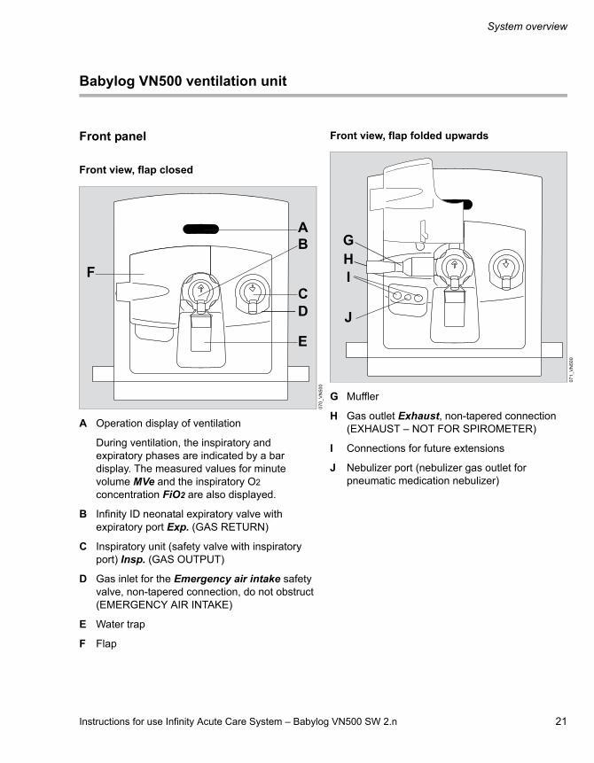
Babylog VN500 ventilation unit
Front panel
Front view, flap closed
A Operation display of ventilation
During ventilation, the inspiratory and expiratory phases are indicated by a bar display. The measured values for minute volume MVe and the inspiratory O2 concentration FiO2 are also displayed.
B Infinity ID neonatal expiratory valve with expiratory port Exp. (GAS RETURN)
C Inspiratory unit (safety valve with inspiratory port) Insp. (GAS OUTPUT)
D Gas inlet for the Emergency air intake safety valve, non-tapered connection, do not obstruct (EMERGENCY AIR INTAKE)
E Water trap
F Flap
Front view, flap folded upwards
G Muffler
H Gas outlet Exhaust, non-tapered connection (EXHAUST – NOT FOR SPIROMETER)
I Connections for future extensions
J Nebulizer port (nebulizer gas outlet for pneumatic medication nebulizer)
07
0_
VN
50
0
AB
C
E
F
D
07
1_
VN
50
0
GH
J
I

System overview
22 Instructions for use Infinity Acute Care System – Babylog VN500 SW 2.n
Rear view
A Fuse for the batteries
B Connection for the neonatal flow sensor V5
C Connections for future extensions V6, V8
D Connection for CO2 sensor V7
E Potential equalization pin
F Fuse for mains power supply F1, F2
G Connection for mains power supply
Left side view
A Connection for system cable to Infinity C500 V1
B Connections for future extensions V2, V3
C Connection for nurse call V4
D Toggle switch
E Ambient air filter with cover
F Strain relief for cable
G Left device flap
00
4
AB
FE
G
DC
00
5_
VN
50
0
AB
DE
G
C
F

Instructions for use Infinity Acute Care System – Babylog VN500 SW 2.n 23
System overview
Right side view A Connection for data cable to the GS500 gas supply unit V9
B Connection for gas connection to the GS500 gas supply unit
C Connection for Air compressed gas hose Air (FRESH GAS)
D Connection for O2 compressed gas hose O2 (FRESH GAS)
E Right device flap
Trolley 2 - 90 cm
A Mount for Infinity C500
B Handle
C Trolley column
D Hose hooks
E Alignment aid
F Humidifier holder, can be swiveled
G Universal holder with standard rail
H Double castors with locking brake, set of 4
01
4_
VN
50
0
C
D
E
A
B
03
8
A
B
F
H
DC
G
E
D
System overview
24 Instructions for use Infinity Acute Care System – Babylog VN500 SW 2.n
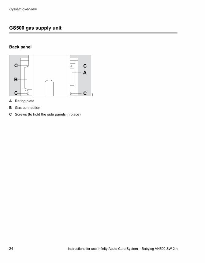
GS500 gas supply unit
Back panel
A Rating plate
B Gas connection
C Screws (to hold the side panels in place)
33
0
A
B
C
CC
C
Instructions for use Infinity Acute Care System – Babylog VN500 SW 2.n 25
System overview
Range of functions
The functions described correspond to the overall functionality of Babylog VN500. Some functions are only optional and may not be included in the individual device configuration. Optional functions are shown in the separate list of accessories.
Ventilation functions of Babylog VN500
Ventilation modes:– Pressure-controlled ventilation:
– PC-SIMV– PC-AC– PC-CMV– PC-APRV– PC-PSV– PC-HFO– PC-MMV
– Support of spontaneous breathing:– SPN-CPAP/PS– SPN-CPAP/VS– SPN-PPS
Additional settings for ventilation:– Apnea Ventilation– Flow trigger– Sigh– Volume Guarantee– ATC– AutoRelease– HFO-Sigh– Volume Guarantee (HFO)
Special functions:– Maneuvers
– Manual inspiration/hold– Suction maneuver
– Medication nebulization
Therapy types:– Invasive ventilation (Tube)– O2 Therapy– Non-invasive ventilation (NIV)
Additional information
For a detailed description of the ventilation modes and the additional settings see page 290. Abbreviations see page 27.
Monitoring
Patient monitoring is supported by the following alarm limit settings:– Maximum airway pressure Paw– Expiratory minute volume MVe– Apnea alarm time Tapn– Respiratory rate RR– End-expiratory CO2 concentration etCO2
The inspiratory O2 concentration is monitored by automatically set limits.
Babylog VN500 offers the following displays:– Curves– Graphic trends– Numeric trends– Loops– Alarm history– Logbook– Numeric parameters– Preconfigured lists for measured values and set
values– Customized lists for measured values and set
values– Smart Pulmonary View
During non-invasive ventilation and O2 therapy, certain monitoring functions are switched off or can be switched off.
System overview
26 Instructions for use Infinity Acute Care System – Babylog VN500 SW 2.n
Power supply
Babylog VN500 is designed for connection to the hospital's mains power supply of 100 to 240 V at 50/60 Hz.
If mains power fails, operation is maintained either via the internal battery of Babylog VN500 or via the PS500 power supply unit.
Gas supply
Babylog VN500 features country-specific connections for the gas supply with oxygen and medical compressed air.
The Workstation Neonatal Care may also be equipped with the GS500 external gas supply unit. GS500 supplies Babylog VN500 with compressed air.
Data transfer
A variety of interfaces can be used for transferring data:– USB port for data export and configuration
exchange using a USB storage medium– USB port for installation of optional applications
via a SIM card reader and a SIM card– RS232 port on Infinity C500 for data transfer
using the MEDIBUS or MEDIBUS.X protocol
Medication nebulizer
For medication nebulization a pneumatic medication nebulizer can be connected.
Attaching accessories
Accessories can be attached to the following holders:– Universal holder with standard rail (G93140)– Humidifier holder, can be swiveled (G93111)– Humidifier holder for the lateral standard rail
(8416325)
Observe the permitted maximum distance to the trolley and the permitted maximum load, see "Maximum loads of holders" on page 44.

Instructions for use Infinity Acute Care System – Babylog VN500 SW 2.n 27
System overview
Abbreviations
Abbreviation Explanation
% leak Leakage in percent
%MVspon Spontaneous breathing portion of minute volume in percent
%PEF Percentage of the peak expiratory flow
%PIF Percentage of the peak inspiratory flow
Ah Ampere hours (output specification for batteries)
Air Connection for Air compressed gas hose (FRESH GAS)
ALARM RESET
Acknowledging an alarm message that is no longer active ("Reset")
Ampl hf Pressure amplitude for HFO (set value)
Ampl hf max Maximum pressure amplitude for HFO (VG)
Apnea Vent. Apnea ventilation
APRV Airway Pressure Release Ventilation
ATC Automatic Tube Compensation, compensation of the tube resistance
Audio paused Suppress acoustic alarm for 2 minutes:– Infinity C500 (MK31500):
with the key – Infinity C500 (MS18746):
with the key
BF Insulation class Body Floating
BTPS Body Temperature Pressure Saturated, measured values based on the condition of the patient's lungs, body temperature 37 °C (98.6 °F), water vapor-saturated gas, ambient pressure and mean airway pressure
Audio paused
C Compliance
C20/Cdyn Index of the last 20 % of compliance in relation to the dynamic total compliance
Cdyn Dynamic compliance
cmH2O Unit of measurement for pressure1 cmH2O = approx. 1 mbar
Compens. Degree of tube compensation
COPD Chronic Obstructive Pulmonary Disease
Cycles sigh Number of cycles during a sigh phase (set value)
DCO2 Dissociation coefficient for CO2 with HFO
Device flow Delivered inspiratory flow with PC-HFO
DHCP Dynamic Host Configuration Protocol
intPEEP Additional intermittent PEEP for sigh (set value)
Phf Maximum pressure difference of amplitude with HFO
Psupp Pressure support relative (above PEEP) (set value)
E Elastance
EIP End Inspiratory Pressure
EMC Electromagnetic compatibility
Emergency air intake
Safety air inlet, inspiratory relief valve (EMERGENCY AIR INTAKE)
ESD Electrostatic Discharge
ET Endotracheal tube
etCO2 End-expiratory CO2 concentration
ETSI European Telecommunications Standards Institute
Abbreviation Explanation
System overview
28 Instructions for use Infinity Acute Care System – Babylog VN500 SW 2.n
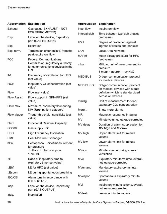
Exhaust Gas outlet (EXHAUST – NOT FOR SPIROMETER)
Exp. Label on the device, Expiratory port (GAS RETURN)
Exp. Expiration
Exp. term. Termination criterion in % from the peak expiratory flow
FCC Federal Communications Commission, regulatory authority for communications devices in the U.S.
fhf Frequency of oscillation for HFO (set value)
FiO2 Inspiratory O2 concentration (set value)
Flow Flow (set value)
Flow Assist Flow support in SPN-PPS (set value)
Flow max Maximum inspiratory flow during NIV (Neo. patient category)
Flow trigger Trigger threshold, sensitivity (set value)
FRC Functional Residual Capacity
GS500 Gas supply unit
HFO High Frequency Oscillation
HME Heat Moisture Exchanger
hPa Hectopascal, unit of measurement for pressure1 hPa = 1 mbar = approx. 1 cmH2O
I:E Ratio of inspiratory time to expiratory time (set value)
I:Ehf I:E for HFO (set value)
I:Espon I:E during spontaneous breathing
IEC/CEI Alarm tone in accordance with IEC 60601-1-8
Insp. Label on the device, Inspiratory port (GAS OUTPUT)
Insp. Inspiration
Abbreviation Explanation
Insp. flow Inspiratory flow
Interval sigh Time between two sigh phases (set value)
IP21 Degree of protection against ingress of liquids and particles
LAN Local Area Network
MAPhf Mean airway pressure for HFO (set value)
mbar Millibar, unit of measurement for pressure1 mbar = approx. 1 cmH2O
MEDIBUS Dräger communication protocol for medical devices
MEDIBUS.X Dräger communication protocol for medical devices with a data definition which is standardized across all devices
mmHg Unit of measurement for end-expiratory CO2 concentration
More... Show more alarms
MRI Magnetic resonance imaging
MV Minute volume, leakage-corrected
MV delay Duration of alarm suppression for MV high and MV low
MV high Upper alarm limit for minute volume
MV low Lower alarm limit for minute volume
MVapn Minute volume during apnea ventilation
MVe Expiratory minute volume, overall, not leakage-corrected
MVemand Mandatory expiratory minute volume
MVespon Spontaneous expiratory minute volume
MVi Inspiratory minute volume, overall, not leakage-corrected
MVleak Leakage minute volume
Abbreviation Explanation
Instructions for use Infinity Acute Care System – Babylog VN500 SW 2.n 29
System overview
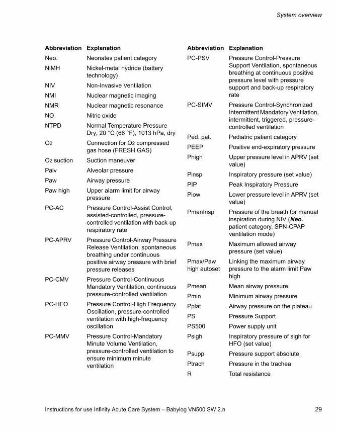
Neo. Neonates patient category
NiMH Nickel-metal hydride (battery technology)
NIV Non-Invasive Ventilation
NMI Nuclear magnetic imaging
NMR Nuclear magnetic resonance
NO Nitric oxide
NTPD Normal Temperature Pressure Dry, 20 °C (68 °F), 1013 hPa, dry
O2 Connection for O2 compressed gas hose (FRESH GAS)
O2 suction Suction maneuver
Palv Alveolar pressure
Paw Airway pressure
Paw high Upper alarm limit for airway pressure
PC-AC Pressure Control-Assist Control, assisted-controlled, pressure-controlled ventilation with back-up respiratory rate
PC-APRV Pressure Control-Airway Pressure Release Ventilation, spontaneous breathing under continuous positive airway pressure with brief pressure releases
PC-CMV Pressure Control-Continuous Mandatory Ventilation, continuous pressure-controlled ventilation
PC-HFO Pressure Control-High Frequency Oscillation, pressure-controlled ventilation with high-frequency oscillation
PC-MMV Pressure Control-Mandatory Minute Volume Ventilation, pressure-controlled ventilation to ensure minimum minute ventilation
Abbreviation Explanation
PC-PSV Pressure Control-Pressure Support Ventilation, spontaneous breathing at continuous positive pressure level with pressure support and back-up respiratory rate
PC-SIMV Pressure Control-Synchronized Intermittent Mandatory Ventilation, intermittent, triggered, pressure-controlled ventilation
Ped. pat. Pediatric patient category
PEEP Positive end-expiratory pressure
Phigh Upper pressure level in APRV (set value)
Pinsp Inspiratory pressure (set value)
PIP Peak Inspiratory Pressure
Plow Lower pressure level in APRV (set value)
PmanInsp Pressure of the breath for manual inspiration during NIV (Neo. patient category, SPN-CPAP ventilation mode)
Pmax Maximum allowed airway pressure (set value)
Pmax/Paw high autoset
Linking the maximum airway pressure to the alarm limit Paw high
Pmean Mean airway pressure
Pmin Minimum airway pressure
Pplat Airway pressure on the plateau
PS Pressure Support
PS500 Power supply unit
Psigh Inspiratory pressure of sigh for HFO (set value)
Psupp Pressure support absolute
Ptrach Pressure in the trachea
R Total resistance
Abbreviation Explanation

System overview
30 Instructions for use Infinity Acute Care System – Babylog VN500 SW 2.n
r² Correlation coefficient for the calculation method "Least Mean Square" for R, C and TC
REF Material and revision number of the medical device
RF Radio Frequency
RFID Radio Frequency Identification
Rpat Patient resistance, patient airway resistance
RR Respiratory rate (set value)
RR high Upper alarm limit for respiratory rate
RRapn Respiratory rate of apnea ventilation (set value)
RRmand Mandatory portion of respiratory rate
RRsigh Respiratory rate of the sighs during HFO (set value)
RRspon Spontaneous breathing portion of respiratory rate
RRtrig Portion of mandatory triggered breaths
RSB Rapid Shallow Breathing, quotient of spontaneous respiratory rate and tidal volume
SIM Subscriber Identity Module, participant identification
Slope Pressure rise time (set value)
Slopesigh Pressure rise time of the sighs during HFO
Smart Pulmonary View
Graphic display of lung characteristics (Lung display)
SN Device serial number
SPN-CPAP Spontaneous-Continuous Positive Airway Pressure, spontaneous breathing with continuous positive pressure level
Abbreviation Explanation
SPN-CPAP/PS
Spontaneous-Continuous Positive Airway Pressure/Pressure Support, spontaneous breathing with continuous positive pressure level with or without pressure support
SPN-CPAP/VS
Spontaneous-Continuous Positive Airway Pressure/Volume Support, spontaneous breathing with continuous positive pressure level with or without volume support
SPN-PPS Spontaneous-Proportional Pressure Support, spontaneous breathing with flow-proportional and volume-proportional pressure support
SpO2 Partial O2 saturation
STPD Standard Temperature Pressure Dry, 0 °C (32 °F), 1013 hPa, dry
Tapn Apnea alarm time (set value)
TC Time constant tau
TCe Time constant calculated from VTe and peak expiratory flow
Tdisconnect Time for disconnection alarm (set value)
Te Expiratory time (set value)
TGI Tracheal Gas Insufflation,tracheal gas insufflation
Thigh Time of upper pressure level in APRV (set value)
Ti Inspiratory time (set value)
Timax Maximum inspiratory time for flow during pressure or volume support (set value)
Tisigh Inspiratory time of sigh for HFO (set value)
Tispon Inspiratory time during spontaneous breathing
Tisupp Inspiratory time during pressure support
Abbreviation Explanation

Instructions for use Infinity Acute Care System – Babylog VN500 SW 2.n 31
System overview
Tlow Time of lower pressure level in APRV
Tlow max Maximum expiratory time during APRV (set value)
TmanInsp Duration of the breath for manual inspiration during NIV (patient category Neo., ventilation mode SPN-CPAP)
Tplat Time of inspiratory plateau
Trach. Tracheostomy tube
Tube Ø Inner diameter of tube (set value)
UMDNS Universal Medical Device Nomenclature System, nomenclature for medical devices
UN Rated voltage
USB Universal Serial Bus, serial bus system
VG Volume Guarantee, Volume Guarantee
VG (HF) Volume Guarantee for HFO
Vol. Assist Volume support in SPN-PPS (set value)
VRLA Valve-regulated lead-acid (battery technology)
VS Volume Support
VT Tidal volume, leakage-corrected
VTapn Tidal volume of apnea ventilation (set value)
VTe Expiratory tidal volume, not leakage-corrected
VTemand Expiratory tidal volume during a mandatory breath
VTespon Expiratory tidal volume during a spontaneous breath
VThf Tidal volume for HFO (set value for VG (HF))
VTi Inspiratory tidal volume, not leakage-corrected
Abbreviation Explanation
VTimand Inspiratory tidal volume during a mandatory breath
VTispon Inspiratory tidal volume during a spontaneous breath
VTmand Tidal volume during a mandatory breath
VTmax Maximum tidal volume in SPN-PPS (set value)
VTspon Tidal volume during a spontaneous breath
Abbreviation Explanation

System overview
32 Instructions for use Infinity Acute Care System – Babylog VN500 SW 2.n
Symbols
Symbol Explanation
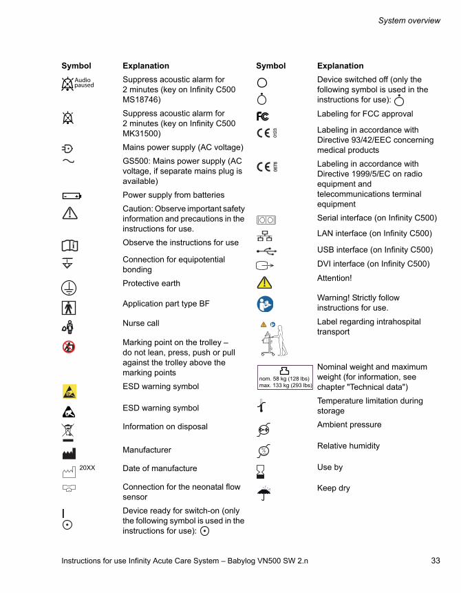
Acoustic alarm suppressed for 2 minutes
Group Views, screen displays
Group Trends/Data, information on the course of ventilation
Group Special maneuvers
Group Alarms
Group Therapy, ventilation parameter settings
Group configuration, system settings, and settings for sensors
Group Start/Standby
Switch system on or off (with the key on Infinity C500)
Alarm limit off
Configure trends
Save screen display
View 1
View 2
View 3
Medication nebulizer
Charge state of batteries 90 to 100 %
Charge state of batteries 60 to <90 %
Charge state of batteries 40 to <60 %
Charge state of batteries 20 to <40 %
Charge state of batteries <20 %
1 2 3
1 2 3
1 2 3
Batteries defective or no information available on their charge state
Lower alarm limit
Upper alarm limit
Setting or access locked
Expiratory valve locked
Setting or access unlocked
Expiratory valve unlocked
Gas outlet (EXHAUST – NOT FOR SPIROMETER)
Pediatric patient category (Ped. pat.)
Neonates patient category (Neo.)
Display additional information or open Help
Hide additional information or close Help
Scroll back in tables or lists
Scroll forward in tables or lists
Scroll forward in Help
Scroll backward in Help
Close dialog window
Active test in the device check
Spontaneous breathing activity by the patient
NIV, Non-invasive ventilation
Symbol Explanation
Exhaust
Instructions for use Infinity Acute Care System – Babylog VN500 SW 2.n 33
System overview
Suppress acoustic alarm for 2 minutes (key on Infinity C500 MS18746)
Suppress acoustic alarm for 2 minutes (key on Infinity C500 MK31500)
Mains power supply (AC voltage)
GS500: Mains power supply (AC voltage, if separate mains plug is available)
Power supply from batteries
Caution: Observe important safety information and precautions in the instructions for use.
Observe the instructions for use
Connection for equipotential bonding
Protective earth
Application part type BF
Nurse call
Marking point on the trolley – do not lean, press, push or pull against the trolley above the marking points
ESD warning symbol
ESD warning symbol
Information on disposal
Manufacturer
20XX Date of manufacture
Connection for the neonatal flow sensor
Device ready for switch-on (only the following symbol is used in the instructions for use):
Symbol Explanation
Audio paused
Device switched off (only the following symbol is used in the instructions for use):
Labeling for FCC approval
Labeling in accordance with Directive 93/42/EEC concerning medical products
Labeling in accordance with Directive 1999/5/EC on radio equipment and telecommunications terminal equipment
Serial interface (on Infinity C500)
LAN interface (on Infinity C500)
USB interface (on Infinity C500)
DVI interface (on Infinity C500)
Attention!
Warning! Strictly follow instructions for use.
Label regarding intrahospital transport
Nominal weight and maximum weight (for information, see chapter "Technical data")
Temperature limitation during storage
Ambient pressure
Relative humidity
Use by
Keep dry
Symbol Explanation
nom. 58 kg (128 lbs)max. 133 kg (293 lbs)

34 Instructions for use Infinity Acute Care System – Babylog VN500 SW 2.n
This page has been left blank intentionally.

Instructions for use Infinity Acute Care System – Babylog VN500 SW 2.n 35
Operating concept
Operating concept
Operating concept for Infinity C500 . . . . . . . 36
Operating concept for Babylog VN500. . . . . 36
Main screen . . . . . . . . . . . . . . . . . . . . . . . . . . . 36Main menu bar . . . . . . . . . . . . . . . . . . . . . . . . . 37Dialog windows. . . . . . . . . . . . . . . . . . . . . . . . . 38Therapy bar . . . . . . . . . . . . . . . . . . . . . . . . . . . 38Therapy controls. . . . . . . . . . . . . . . . . . . . . . . . 38Setting ventilation parameters . . . . . . . . . . . . . 39Exceeding the set limit of a ventilation parameter . . . . . . . . . . . . . . . . . . . . . . . . . . . . . 39Direct setting of ventilation parameters (QuickSet). . . . . . . . . . . . . . . . . . . . . . . . . . . . . 39Linked setting of ventilation parameters . . . . . . 40
Operating concept
36 Instructions for use Infinity Acute Care System – Babylog VN500 SW 2.n
Operating concept for Infinity C500
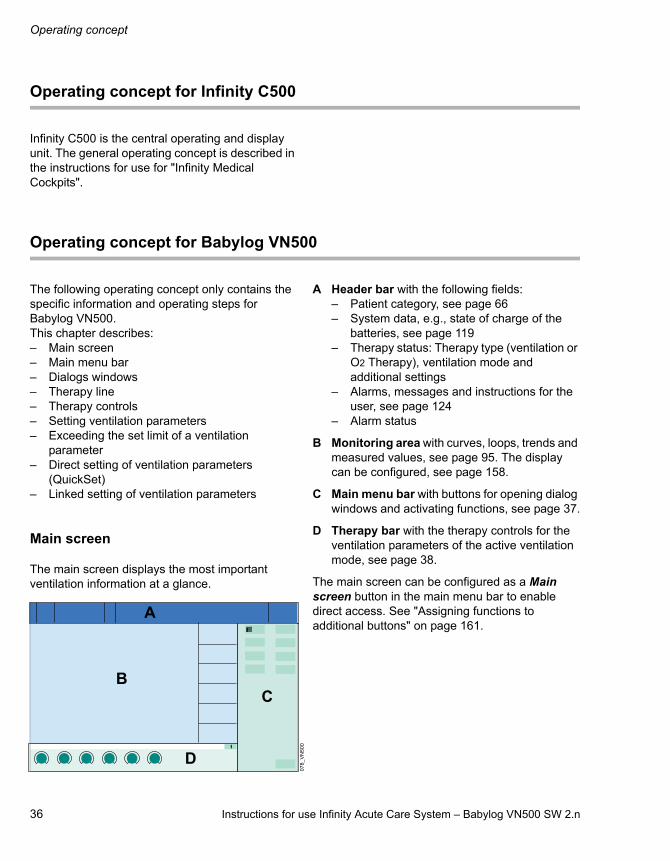
Infinity C500 is the central operating and display unit. The general operating concept is described in the instructions for use for "Infinity Medical Cockpits".
Operating concept for Babylog VN500
The following operating concept only contains the specific information and operating steps for Babylog VN500.This chapter describes:– Main screen– Main menu bar– Dialogs windows– Therapy line– Therapy controls– Setting ventilation parameters– Exceeding the set limit of a ventilation
parameter– Direct setting of ventilation parameters
(QuickSet)– Linked setting of ventilation parameters
Main screen
The main screen displays the most important ventilation information at a glance.
A Header bar with the following fields:– Patient category, see page 66– System data, e.g., state of charge of the
batteries, see page 119– Therapy status: Therapy type (ventilation or
O2 Therapy), ventilation mode and additional settings
– Alarms, messages and instructions for the user, see page 124
– Alarm status
B Monitoring area with curves, loops, trends and measured values, see page 95. The display can be configured, see page 158.
C Main menu bar with buttons for opening dialog windows and activating functions, see page 37.
D Therapy bar with the therapy controls for the ventilation parameters of the active ventilation mode, see page 38.
The main screen can be configured as a Main screen button in the main menu bar to enable direct access. See "Assigning functions to additional buttons" on page 161.
07
8_
VN
50
0
1 2 3
A
BC
D

Instructions for use Infinity Acute Care System – Babylog VN500 SW 2.n 37
Operating concept
Main menu bar
The main menu bar contains fixed assigned and configurable buttons. The buttons are assigned to various groups. Touching a button opens the corresponding dialog window or activates the corresponding function.
Fixed assigned buttons
A Alarms... for setting the alarm limits, displaying the alarm logbook and listing all active alarms, see page 124.
B Ventilation settings... for setting the ventilation mode and the ventilation parameters, see page 84.
C Sensors/ Parameters... for calibrating the sensors and activating or deactivating monitoring, see page 141.
D System setup... for configuring the device functions, see page 155.
E Start/ Standby... for selecting standby mode or starting therapy, see page 114.
F Views... for switching to other configured monitoring area views, see page 95.
G Trends/Data... for displaying all the measured and set values, logbook, trends and for exporting data, see page 133.
H Special maneuvers... for selecting additional functions, e.g. suction maneuver, see page 101, or medication nebulization, see page 103.
Configurable buttons
Additional buttons for directly accessing functions or dialogs can be configured. These buttons are spatially assigned to the corresponding group. See "Assigning functions to additional buttons" on page 161.
10
0
A
B
C
D
E
H
G
F
Operating concept
38 Instructions for use Infinity Acute Care System – Babylog VN500 SW 2.n
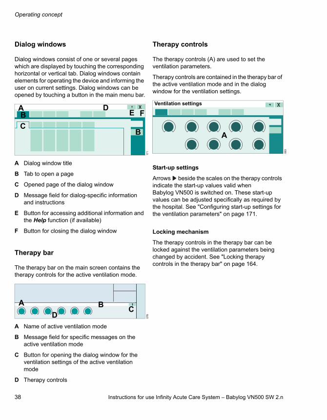
Dialog windows
Dialog windows consist of one or several pages which are displayed by touching the corresponding horizontal or vertical tab. Dialog windows contain elements for operating the device and informing the user on current settings. Dialog windows can be opened by touching a button in the main menu bar.
A Dialog window title
B Tab to open a page
C Opened page of the dialog window
D Message field for dialog-specific information and instructions
E Button for accessing additional information and the Help function (if available)
F Button for closing the dialog window
Therapy bar
The therapy bar on the main screen contains the therapy controls for the active ventilation mode.
A Name of active ventilation mode
B Message field for specific messages on the active ventilation mode
C Button for opening the dialog window for the ventilation settings of the active ventilation mode
D Therapy controls
Therapy controls
The therapy controls (A) are used to set the ventilation parameters.
Therapy controls are contained in the therapy bar of the active ventilation mode and in the dialog window for the ventilation settings.
Start-up settings
Arrows beside the scales on the therapy controls indicate the start-up values valid when Babylog VN500 is switched on. These start-up values can be adjusted specifically as required by the hospital. See "Configuring start-up settings for the ventilation parameters" on page 171.
Locking mechanism
The therapy controls in the therapy bar can be locked against the ventilation parameters being changed by accident. See "Locking therapy controls in the therapy bar" on page 164.
17
10
78
B
CB
DE F
A
A BC
D
08
3
A
Ventilation settings

Instructions for use Infinity Acute Care System – Babylog VN500 SW 2.n 39
Operating concept
Setting ventilation parameters
1 Touch the therapy control. The color turns yellow. The unit of the parameter to be adjusted is displayed in parentheses.
2 Turn the rotary knob to set the value.
3 Press the rotary knob to confirm the value. The color of the therapy control turns dark green.
The following chapters of the instructions for use provide a simplified explanation of these steps: "Use the rotary knob to set and confirm the value."
Exceeding the set limit of a ventilation parameter
When a set limit of a parameter has been reached, Babylog VN500 displays a message.
Press the rotary knob to exceed the set limit.
The set limit can be exceeded.
If the maximum set limit for a parameter has been reached, e.g., when it is dependent on other parameters, it is not possible to exceed the set limit.
Press the rotary knob. Babylog VN500 adopts the maximum possible set value.
Direct setting of ventilation parameters (QuickSet)
When a ventilation parameter is set directly, the changes to a setting become immediately effective for the patient. The user can immediately see the effect the changed setting has on the patient. The finally chosen setting does not have to be confirmed again.
Ventilation parameters can be set directly in all ventilation modes and can be carried out in the dialog window for the ventilation settings. Direct settings are only possible in the therapy bar when the therapy controls are not locked.
O2 and Flow cannot be set directly.
Setting ventilation parameters directly
1 Touch the corresponding therapy control.
2 Press the rotary knob and hold for approximately 3 seconds.
The therapy control changes to dark green with a yellow edge. The direct setting function is now active.
3 Press and hold the rotary knob and turn to set the value.
The set value is immediately effective.
Exceeding the set limit of a parameter with direct setting
When a set limit of a parameter has been reached, Babylog VN500 displays a message.
4 Release rotary knob for a short moment.
5 Press the rotary knob again and turn it.
The set limit can be exceeded.
12
8
08
7
Operating concept
40 Instructions for use Infinity Acute Care System – Babylog VN500 SW 2.n
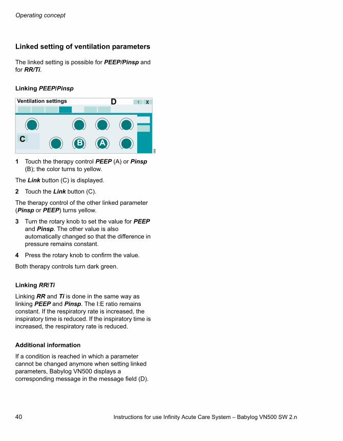
Linked setting of ventilation parameters
The linked setting is possible for PEEP/Pinsp and for RR/Ti.
Linking PEEP/Pinsp
1 Touch the therapy control PEEP (A) or Pinsp (B); the color turns to yellow.
The Link button (C) is displayed.
2 Touch the Link button (C).
The therapy control of the other linked parameter (Pinsp or PEEP) turns yellow.
3 Turn the rotary knob to set the value for PEEP and Pinsp. The other value is also automatically changed so that the difference in pressure remains constant.
4 Press the rotary knob to confirm the value.
Both therapy controls turn dark green.
Linking RR/Ti
Linking RR and Ti is done in the same way as linking PEEP and Pinsp. The I:E ratio remains constant. If the respiratory rate is increased, the inspiratory time is reduced. If the inspiratory time is increased, the respiratory rate is reduced.
Additional information
If a condition is reached in which a parameter cannot be changed anymore when setting linked parameters, Babylog VN500 displays a corresponding message in the message field (D).
08
5
B AC
DVentilation settings

Instructions for use Infinity Acute Care System – Babylog VN500 SW 2.n 41
Assembly and preparation
Assembly and preparation
Safety information for assembly and preparation . . . . . . . . . . . . . . . . . . . . . . . . . . . 42
Preparing the trolley. . . . . . . . . . . . . . . . . . . . 42
Safety information on the trolley . . . . . . . . . . . . 42Connecting the universal holder with standard rail to the trolley . . . . . . . . . . . . . . . . . 43Connecting the humidifier holder to the trolley . . . . . . . . . . . . . . . . . . . . . . . . . . . . . . . . 43Securing accessories to the standard rail. . . . . 44Securing the compressed gas cylinders to the trolley . . . . . . . . . . . . . . . . . . . . . . . . . . . . . 44
Preparing the Medical Cockpit . . . . . . . . . . . 46
Positioning Infinity C500. . . . . . . . . . . . . . . . . . 46Positioning Infinity C500. . . . . . . . . . . . . . . . . . 46Connecting the system cable . . . . . . . . . . . . . . 47Using the MEDIBUS or the MEDIBUS.X protocol. . . . . . . . . . . . . . . . . . . . . . . . . . . . . . . 48LAN and USB interfaces of Infinity C500 . . . . . 49
Preparing the ventilation unit . . . . . . . . . . . . 50
Preparing the Infinity ID neonatal expiratory valve . . . . . . . . . . . . . . . . . . . . . . . . . . . . . . . . . 50Safety information for the use of HMEs, bacterial filters, and breathing circuits . . . . . . . 52Preparing the breathing gas humidifier. . . . . . . 53Connecting the breathing circuit . . . . . . . . . . . . 54Installing a neonatal flow sensor . . . . . . . . . . . 55Replacing the neonatal flow sensor insert . . . . 56Installing a CO2 cuvette and CO2 sensor . . . . . 57Connecting the mains power supply to Babylog VN500. . . . . . . . . . . . . . . . . . . . . . . . . 58Connecting the mains power supply to the GS500 gas supply unit . . . . . . . . . . . . . . . . . . . 59Power supply from batteries . . . . . . . . . . . . . . . 59Failure of the power supply . . . . . . . . . . . . . . . 59Potential equalization . . . . . . . . . . . . . . . . . . . . 59Connecting the gas supply . . . . . . . . . . . . . . . . 60Connecting the nurse call . . . . . . . . . . . . . . . . . 61Closing the flaps at the side of the device . . . . 62
Intrahospital transport . . . . . . . . . . . . . . . . . . 62

Assembly and preparation
42 Instructions for use Infinity Acute Care System – Babylog VN500 SW 2.n
Safety information for assembly and preparation
Preparing the trolley
Safety information on the trolley
WARNING
Before each use, reprocess the device and all accessories in accordance with the instructions for use, see "Reprocessing list" on page 236. Observe the hospital hygiene regulations!
WARNING
Securely mount Babylog VN500. Check for secure fit. Danger of damage to device or personal injury!
WARNING
Risk of tipping over
Do not tilt the device by more than 5°.
WARNING
Do not place any containers with liquid on or above the device! Penetrating liquid may cause malfunction of or damage to the device, which may endanger the patient.
WARNING
Failure to observe the permitted maximum load and weight distribution may result in the device toppling over. Danger of damage to device or personal injury! Observe the permitted maximum load and weight distribution, see "Maximum load" on page 279.
CAUTION
When parking the device, lock all the double castors of the trolley and check that the brakes are working properly.
WARNING
Do not use the trolley in the event of visible damage, e.g., damaged double castors! Contact DrägerService.
WARNING
Do not lean, press, push or pull against the trolley above the marking points on the trolley. The trolley could topple over.
CAUTION
Connect all devices securely to the trolley. Check for secure fit. Danger of damage to device or personal injury!

Instructions for use Infinity Acute Care System – Babylog VN500 SW 2.n 43
Assembly and preparation
Connecting the universal holder with standard rail to the trolley
Attach the universal holder with standard rail to the front of the trolley.
1 Unscrew the adjusting screw (A) completely.
2 Attach the right-hand side of the universal holder to the right-hand side of the rail (B). Make sure that the catch of the universal holder is completely behind the alignment aid.
3 Align the universal holder (C) horizontally and press the left-hand side of the universal holder onto the left-hand side of the column.
4 Tighten the adjusting screw (A). Make sure that the catch of the universal holder is completely behind the alignment aid.
5 Check that the universal holder is fixed securely.
Adjusting the height of the universal holder
1 Unscrew the adjusting screw (A).
2 Adjust the height of the universal holder (C).
3 Align the universal holder horizontally.
4 Retighten the adjusting screw (A).
Connecting the humidifier holder to the trolley
The humidifier holder is attached to the front of the trolley. The humidifier holder can be fastened on the left or right-hand side of the trolley column. The attachment of the humidifier holder on the right-hand side is shown.
1 Hold the humidifier holder at the desired height on the guide (A) of the trolley column.
2 Turn the clamping screw (B) to the left until the base (C) fits into the guide of the trolley column.
3 Turn the clamping screw (B) to the right until the humidifier holder is secured firmly in the guide.
4 Move the standard rail (D) to the desired position.
04
9
A
BC
Front of the trolley
19
2
B
C
D
AFront of the trolley
Assembly and preparation
44 Instructions for use Infinity Acute Care System – Babylog VN500 SW 2.n
Securing accessories to the standard rail
Maximum loads of holders
The following information applies to the holders:
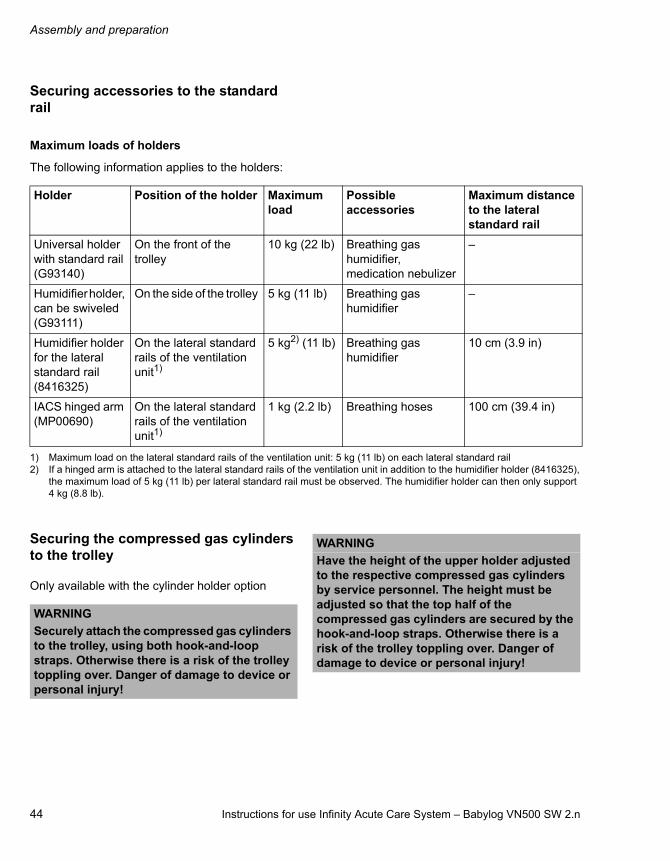
Securing the compressed gas cylinders to the trolley
Only available with the cylinder holder option
Holder Position of the holder Maximum load
Possible accessories
Maximum distance to the lateral standard rail
Universal holder with standard rail (G93140)
On the front of the trolley
10 kg (22 lb) Breathing gas humidifier, medication nebulizer
–
Humidifier holder, can be swiveled (G93111)
On the side of the trolley 5 kg (11 lb) Breathing gas humidifier
–
Humidifier holder for the lateral standard rail (8416325)
On the lateral standard rails of the ventilation unit1)
1) Maximum load on the lateral standard rails of the ventilation unit: 5 kg (11 lb) on each lateral standard rail
5 kg2) (11 lb)
2) If a hinged arm is attached to the lateral standard rails of the ventilation unit in addition to the humidifier holder (8416325), the maximum load of 5 kg (11 lb) per lateral standard rail must be observed. The humidifier holder can then only support 4 kg (8.8 lb).
Breathing gas humidifier
10 cm (3.9 in)
IACS hinged arm (MP00690)
On the lateral standard rails of the ventilation unit1)
1 kg (2.2 lb) Breathing hoses 100 cm (39.4 in)
WARNING
Securely attach the compressed gas cylinders to the trolley, using both hook-and-loop straps. Otherwise there is a risk of the trolley toppling over. Danger of damage to device or personal injury!
WARNING
Have the height of the upper holder adjusted to the respective compressed gas cylinders by service personnel. The height must be adjusted so that the top half of the compressed gas cylinders are secured by the hook-and-loop straps. Otherwise there is a risk of the trolley toppling over. Danger of damage to device or personal injury!

Instructions for use Infinity Acute Care System – Babylog VN500 SW 2.n 45
Assembly and preparation
Compressed gas cylinders with the following dimensions can be secured:
1 Place the cylinders into the mountings on the trolley.
2 Secure each cylinder with 2 hook-and-loop straps (A).
3 Secure the compressed gas hoses by hanging them over the hose hooks (B).
WARNING
The length of the hook-and-loop straps must match the diameter of the compressed gas cylinders to ensure that the hook-and-loop straps can hold the cylinders securely. If necessary have an appropriate hook-and-loop strap fitted by service personnel. This is essential to ensure that the compressed gas cylinders are properly secured.
Diameter: 80 to 176 mm (3.15 to 6.93 in)
Length: 420 to 760 mm (16.54 to 29.92 in)
WARNING
Not every combination of compressed gas cylinder diameter and length can be secured. When used in combination with a pressure reducer, the compressed gas cylinder must not come into contact with the console of the trolley. The maximum diameter is 176 mm (6.93 in) when the base of the compressed gas cylinder is resting completely on the base plate of the lower holder or is semi-spherical in shape.
19
3
WARNING
Position the compressed gas cylinders fitted with pressure reducers in such a way to prevent the pressure reducers from being damaged during transport. The lower part of the trolley is designed to protect against collisions. Take particular care when the compressed gas cylinders being used extend beyond this collision protection.
A
AA
A
B
B
Assembly and preparation
46 Instructions for use Infinity Acute Care System – Babylog VN500 SW 2.n
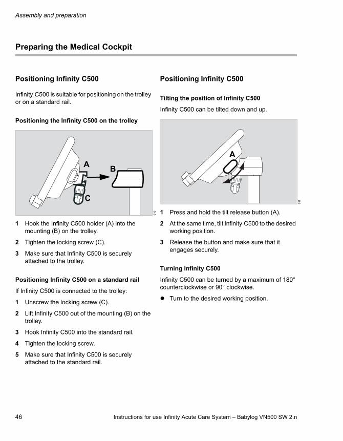
Preparing the Medical Cockpit
Positioning Infinity C500
Infinity C500 is suitable for positioning on the trolley or on a standard rail.
Positioning the Infinity C500 on the trolley
1 Hook the Infinity C500 holder (A) into the mounting (B) on the trolley.
2 Tighten the locking screw (C).
3 Make sure that Infinity C500 is securely attached to the trolley.
Positioning Infinity C500 on a standard rail
If Infinity C500 is connected to the trolley:
1 Unscrew the locking screw (C).
2 Lift Infinity C500 out of the mounting (B) on the trolley.
3 Hook Infinity C500 into the standard rail.
4 Tighten the locking screw.
5 Make sure that Infinity C500 is securely attached to the standard rail.
Positioning Infinity C500
Tilting the position of Infinity C500
Infinity C500 can be tilted down and up.
1 Press and hold the tilt release button (A).
2 At the same time, tilt Infinity C500 to the desired working position.
3 Release the button and make sure that it engages securely.
Turning Infinity C500
Infinity C500 can be turned by a maximum of 180° counterclockwise or 90° clockwise.
Turn to the desired working position.
01
0
B
C
A
011
A

Instructions for use Infinity Acute Care System – Babylog VN500 SW 2.n 47
Assembly and preparation
Connecting the system cable
The system cable is connected to Infinity C500 and to Babylog VN500. The system cable is fixed in a clamp.
Connecting the system cable to Infinity C500
On Infinity C500 (MS18746):
On Infinity C500 (MK31500):
1 Unscrew the cover from the socket (A).
2 Insert the system cable connector (B) into the socket (A). Ensure that the connector is inserted with the correct orientation.
3 Screw the cover back on.
Connecting the system cable to Babylog VN500
1 Open the flap on the left-hand side of Babylog VN500.
2 Run the system cable between Babylog VN500 and the handle.
3 Clip the protective sleeve (C) immediately after the connector (E) onto the system cable (D). Align the protective sleeve so that the slots of the protective sleeve are facing downwards and upwards.
4 Insert the system cable connector (E) into the socket until the connector audibly clicks into place.
5 Insert the protective sleeve (C) into the protective plate (F) at the same time.
6 Turn the protective sleeve (C) by approximately 90° until it clicks into place. The cable is secured.
7 Close the left-hand flap.
Disconnecting the system cable from Babylog VN500
1 Push the locking mechanism on the connector (E) backwards and pull out the connector.
2 Turn the protective sleeve (C) by approximately 90° and withdraw it from the protective plate (F).
01
83
57
A
B
A
B
00
3
C
F
D E
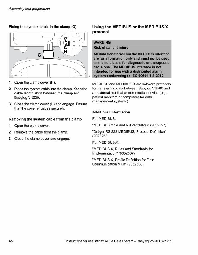
Assembly and preparation
48 Instructions for use Infinity Acute Care System – Babylog VN500 SW 2.n
Fixing the system cable in the clamp (G)
1 Open the clamp cover (H).
2 Place the system cable into the clamp. Keep the cable length short between the clamp and Babylog VN500.
3 Close the clamp cover (H) and engage. Ensure that the cover engages securely.
Removing the system cable from the clamp
1 Open the clamp cover.
2 Remove the cable from the clamp.
3 Close the clamp cover and engage.
Using the MEDIBUS or the MEDIBUS.X protocol
MEDIBUS and MEDIBUS.X are software protocols for transferring data between Babylog VN500 and an external medical or non-medical device (e.g., patient monitors or computers for data management systems).
Additional information
For MEDIBUS:
"MEDIBUS for V and VN ventilators" (9039527)
"Dräger RS 232 MEDIBUS, Protocol Definition" (9028258)
For MEDIBUS.X:
"MEDIBUS.X, Rules and Standards for Implementation" (9052607)
"MEDIBUS.X, Profile Definition for Data Communication V1.n" (9052608)
18
8
GH
WARNING
Risk of patient injury
All data transferred via the MEDIBUS interface are for information only and must not be used as the sole basis for diagnostic or therapeutic decisions. The MEDIBUS interface is not intended for use with a distributed alarm system conforming to IEC 60601-1-8:2012.

Instructions for use Infinity Acute Care System – Babylog VN500 SW 2.n 49
Assembly and preparation
Connecting an external device for using MEDIBUS or MEDIBUS.X
On Infinity C500 (MS18746):
On Infinity C500 (MK31500):
Connect an external device to the COM 1, COM 2 or COM 3 (A) interface of Infinity C500. Use MEDIBUS cable 8416326.
Configuring the interface
A description is given in chapter "Configuring interfaces" on page 185.
LAN and USB interfaces of Infinity C500
On Infinity C500 (MS18746):
On Infinity C500 (MK31500):
Use of LAN interfaces (A) of Infinity C500 is permitted exclusively for service purposes.
Only connect the following to the USB port (B):– USB storage medium– USB SIM card reader– Aerogen nebulizer
00
73
59
A
A
19
53
60
WARNING
Do not simultaneously touch the connectors of the interfaces and the patient. Risk of electric shock.
WARNING
Risk of voltage surges and device malfunctionDo not connect a device that has its own power supply to the USB port, e.g., a printer or external hard drive.
AB B
B
AB B
B

Assembly and preparation
50 Instructions for use Infinity Acute Care System – Babylog VN500 SW 2.n
Preparing the ventilation unit
Preparing the Infinity ID neonatal expiratory valve
The expiratory valve is mounted and then inserted into the ventilation unit.
Fitting the Infinity ID neonatal expiratory valve
1 Fit the diaphragm (A) onto the edge of the expiratory valve housing. Make sure that the diaphragm is fitted properly.
2 If the muffler (B) has been removed, fit the muffler.
3 Fit the water trap container (C).
Open the flap
Open the flap (D) before inserting the expiratory valve.
Open the flap (D) by lifting the lower edge upwards.
WARNING
Only use properly reprocessed expiratory valves which have been sufficiently dried. Otherwise the proper functioning of the device may be impaired and the patient endangered.
32
9
A
B
04
0_
VN
50
00
06
_V
N5
00
C
D
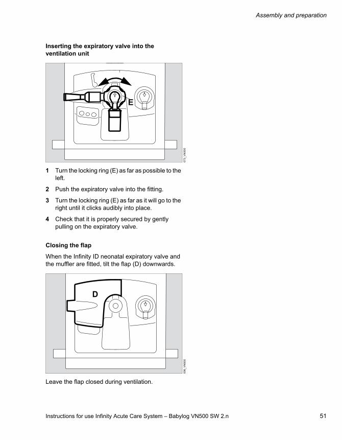
Instructions for use Infinity Acute Care System – Babylog VN500 SW 2.n 51
Assembly and preparation
Inserting the expiratory valve into the ventilation unit
1 Turn the locking ring (E) as far as possible to the left.
2 Push the expiratory valve into the fitting.
3 Turn the locking ring (E) as far as it will go to the right until it clicks audibly into place.
4 Check that it is properly secured by gently pulling on the expiratory valve.
Closing the flap
When the Infinity ID neonatal expiratory valve and the muffler are fitted, tilt the flap (D) downwards.
Leave the flap closed during ventilation.
07
3_
VN
50
00
06
_V
N5
00
E
D

Assembly and preparation
52 Instructions for use Infinity Acute Care System – Babylog VN500 SW 2.n
Safety information for the use of HMEs, bacterial filters, and breathing circuits
Additional components in the breathing circuit can increase the inspiratory and expiratory breathing resistance and exceed standard requirements. Examples: Inspiratory and expiratory bacterial filters, HMEs.
Babylog VN500 is designed to minimize the patient's work of breathing. Operation does therefore not require inspiratory or expiratory bacterial filters. The use of bacterial filters or HMEs requires particular care and monitoring by the user. Especially during medication nebulization and humidification, the resistance of the expiratory bacterial filter may increase gradually.
A higher breathing resistance leads to a greater work of breathing and trigger effort. Under unfavorable conditions, this can lead to an intrinsic PEEP, which can be recognized by the fact that the expiratory flow does not return to "baseline" at the end of expiration. If the PEEP is unacceptably high, this is indicated by an alarm. For additional information, see "Automatic alarm limits" on page 282.
The breathing resistance in the patient connector cannot be monitored directly by Babylog VN500. For this reason:
Before starting ventilation, determine in standby mode inspiratory and expiratory breathing resistance in the breathing circuit by means of the breathing circuit check.
Check the condition of the patient and the device's measured values for volume and resistance more frequently.
Observe the instructions for use for the HMEs, bacterial filters and breathing circuits in use.
WARNING
Increased resistance
Medication nebulization and active humidification may increase the resistance of additional components.
Check the breathing circuit regularly for signs of increased resistance and replace additional components if necessary.
CAUTION
Additional components in the breathing circuit such as bacterial filters, HME or CO2 cuvettes may increase the dead space, compressible volume, and resistance.
Particular care and monitoring are required when using additional components.
Before checking the breathing circuit (see chapter "Getting started"), attach all necessary additional components up to the patient connector.
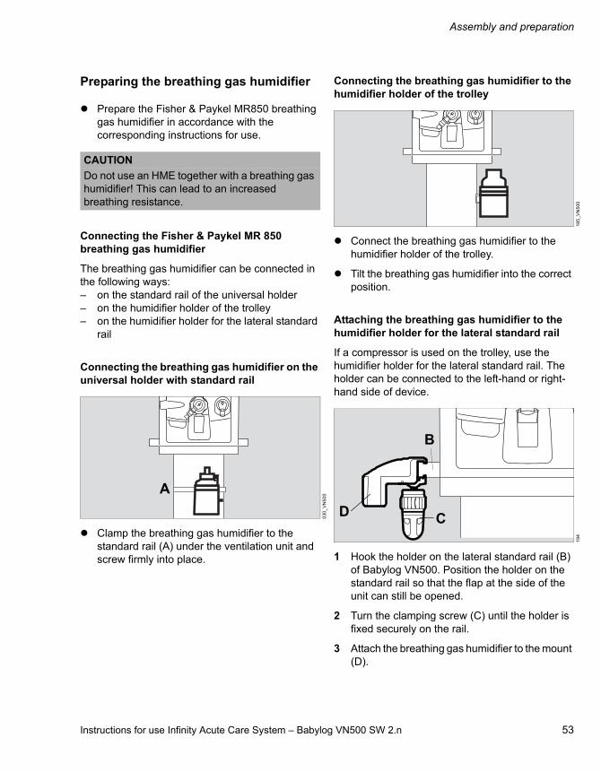
Instructions for use Infinity Acute Care System – Babylog VN500 SW 2.n 53
Assembly and preparation
Preparing the breathing gas humidifier
Prepare the Fisher & Paykel MR850 breathing gas humidifier in accordance with the corresponding instructions for use.
Connecting the Fisher & Paykel MR 850 breathing gas humidifier
The breathing gas humidifier can be connected in the following ways:– on the standard rail of the universal holder– on the humidifier holder of the trolley– on the humidifier holder for the lateral standard
rail
Connecting the breathing gas humidifier on the universal holder with standard rail
Clamp the breathing gas humidifier to the standard rail (A) under the ventilation unit and screw firmly into place.
Connecting the breathing gas humidifier to the humidifier holder of the trolley
Connect the breathing gas humidifier to the humidifier holder of the trolley.
Tilt the breathing gas humidifier into the correct position.
Attaching the breathing gas humidifier to the humidifier holder for the lateral standard rail
If a compressor is used on the trolley, use the humidifier holder for the lateral standard rail. The holder can be connected to the left-hand or right-hand side of device.
1 Hook the holder on the lateral standard rail (B) of Babylog VN500. Position the holder on the standard rail so that the flap at the side of the unit can still be opened.
2 Turn the clamping screw (C) until the holder is fixed securely on the rail.
3 Attach the breathing gas humidifier to the mount (D).
CAUTION
Do not use an HME together with a breathing gas humidifier! This can lead to an increased breathing resistance.
03
0_
VN
50
0
A
18
5_
VN
50
01
94
D C
B

Assembly and preparation
54 Instructions for use Infinity Acute Care System – Babylog VN500 SW 2.n
Additional information
For the order numbers of the holder for the breathing gas humidifier, see the list of accessories.
Connecting the breathing circuit
1 Hang the hinged arm (A) on the lateral standard rail of Babylog VN500 and tighten the screws. Depending on the desired position of the device in relation to the bed, the hinged arm can be fitted to either side of Babylog VN500.
2 Connect breathing hoses to the inspiratory port (B) and to the expiratory port (C).
3 Turn the inspiratory port and expiratory port in the direction of hoses.
A water trap is required for the Fisher & Paykel MR 850 breathing gas humidifier depending on the breathing circuit used.
4 If a water trap is required, install the water trap (D) in a vertical position.
5 Connect the Y-piece (E) to the breathing hoses.
6 Insert the Y-piece or the breathing hoses in the opening of the hinged arm.
Using the Infinity ID breathing circuit
Babylog VN500 recognizes the use of an Infinity ID breathing circuit. The message Infinity ID breathing circuit detected. is displayed in the header bar.
The following Infinity ID functions are supported:– Detection of reversed hoses– Detection of non-compliance with the settings
for the breathing circuit, patient category or humidification type
– Automatic configuration of breathing circuit and humidifier
Automatic configuration of the breathing circuit and the humidifier is only supported in standby mode.
Fit the Infinity ID breathing hoses in standby mode.
If accessories without RFID functionality are combined with Infinity ID accessories, Infinity ID functions may be restricted or unavailable.
WARNING
Do not use antistatic or conductive breathing hoses. The use of these materials increases the risk of electric shock to the patient and of fire in an oxygen-enriched environment.
CAUTION
The sterile packaging of disposable articles must only be opened immediately before use. Otherwise there is a risk of infection.
05
7_
VN
50
0
DE
BCA
CAUTION
Do not reverse the connections for inspiration (B) and expiration (C). Humidification is ineffective if the connections are reversed.
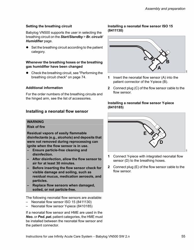
Instructions for use Infinity Acute Care System – Babylog VN500 SW 2.n 55
Assembly and preparation
Setting the breathing circuit
Babylog VN500 supports the user in selecting the breathing circuit on the Start/Standby > Br. circuit/ Humidifier page.
Set the breathing circuit according to the patient category.
Whenever the breathing hoses or the breathing gas humidifier have been changed
Check the breathing circuit, see "Performing the breathing circuit check" on page 74.
Additional information
For the order numbers of the breathing circuits and the hinged arm, see the list of accessories.
Installing a neonatal flow sensor
The following neonatal flow sensors are available:– Neonatal flow sensor ISO 15 (8411130)– Neonatal flow sensor Y-piece (8410185)
If a neonatal flow sensor and HME are used in the Neo. or Ped. pat. patient categories, the HME must be installed between the neonatal flow sensor and the patient connector.
Installing a neonatal flow sensor ISO 15 (8411130)
1 Insert the neonatal flow sensor (A) into the patient connector of the Y-piece (B).
2 Connect plug (C) of the flow sensor cable to the flow sensor.
Installing a neonatal flow sensor Y-piece (8410185)
1 Connect Y-piece with integrated neonatal flow sensor (D) to the breathing hoses.
2 Connect plug (E) of the flow sensor cable to the flow sensor.
WARNING
Risk of fire
Residual vapors of easily flammable disinfectants (e.g., alcohols) and deposits that were not removed during reprocessing can ignite when the flow sensor is in use.– Ensure particle-free cleaning and
disinfection.– After disinfection, allow the flow sensor to
air for at least 30 minutes.– Before inserting the flow sensor check for
visible damage and soiling, such as residual mucus, medication aerosols, and particles.
– Replace flow sensors when damaged, soiled, or not particle-free.
30
03
01
BA
C
D
E

Assembly and preparation
56 Instructions for use Infinity Acute Care System – Babylog VN500 SW 2.n
Further procedure for both neonatal flow sensors
3 Position patient connector of the Y-piece to point approx. 45° downwards to prevent condensation from forming on the neonatal flow sensor.
4 Run the cables along the breathing hoses to the device.
5 Insert the connector (F) of the flow sensor cable into the socket (G) at the rear of Babylog VN500.
Additional information
For the order numbers of the neonatal flow sensor, see the list of accessories.
Replacing the neonatal flow sensor insert
If Babylog VN500 displays the alarm message Neonatal flow sensor?, the insert of the neonatal flow sensor must be replaced.
1 Disconnect plug (A) of the flow sensor cable from the neonatal flow sensor.
2 Gently press the knobs (B) on both sides while pulling the insert (C) out of the flow sensor housing.
3 Push in new insert (C) until it engages.
4 Connect plug (A) of the flow sensor cable to the neonatal flow sensor.
5 Calibrate the neonatal flow sensor, see page 143.
30
2
FG
30
3
A
B
C
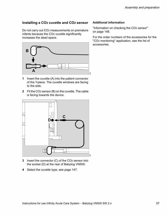
Instructions for use Infinity Acute Care System – Babylog VN500 SW 2.n 57
Assembly and preparation
Installing a CO2 cuvette and CO2 sensor
Do not carry out CO2 measurements on premature infants because the CO2 cuvette significantly increases the dead space.
1 Insert the cuvette (A) into the patient connector of the Y-piece. The cuvette windows are facing to the side.
2 Fit the CO2 sensor (B) on the cuvette. The cable is facing towards the device.
3 Insert the connector (C) of the CO2 sensor into the socket (D) at the rear of Babylog VN500.
4 Select the cuvette type, see page 147.
Additional information
"Information on checking the CO2 sensor" on page 148.
For the order numbers of the accessories for the "CO2 monitoring" application, see the list of accessories.
05
41
80
A
B
DC

Assembly and preparation
58 Instructions for use Infinity Acute Care System – Babylog VN500 SW 2.n
Connecting the mains power supply to Babylog VN500
The mains voltage must conform to the voltage range specified on the rating plate (100 V to 240 V, 50/60 Hz).
1 Plug the appliance socket (A) onto the appliance connector (B).
2 Position the power cable (C) in the clamp (D). Fit the clamp into the housing (E). Tighten the screw (F) (stress relief).
Insert the mains plug into the mains power socket.
The LED on Infinity C500 lights up green.
Checking the toggle switch on Babylog VN500
Prerequisite: The flap on the left-hand side of the device is opened.
Check whether the toggle switch (G) is set to (on).
If the toggle switch is set to (off), set it to (on).
WARNING
Risk of electric shock and of device failure
If the device is connected to a power socket with incorrect mains voltage or without a protective ground, the user can be injured and the device damaged.
Only connect the power cable to power sockets with a protective ground and the correct mains voltage. Observe the technical data.
NOTE
The mains power socket in use must be freely accessible during operation.
00
2
A
B
18
6
CAUTION
Do not press the toggle switch during ventilation.
18
2_
VN
50
0
WARNING
Do not simultaneously touch the connectors of the interfaces (H) and the patient. Risk of electric shock.
D
F
C
E
G
H
Instructions for use Infinity Acute Care System – Babylog VN500 SW 2.n 59
Assembly and preparation
Connecting the mains power supply to the GS500 gas supply unit
If Babylog VN500 is not equipped with the PS500 power supply unit, and the GS500 gas supply unit features a separate mains plug:
Plug the mains plug of the gas supply unit into the mains socket.
The LED on GS500 lights up green.
Power supply from batteries
Charge the batteries completely before initial use.
If the mains power fails, operation is maintained either via the internal battery of Babylog VN500 or via the PS500 power supply unit.
Additional information
For additional information, see "Mains power supply / DC power supply" on page 118.
Failure of the power supply
If the mains power fails, operation is maintained via batteries.
If the mains power fails and the batteries are discharged, Babylog VN500 issues a power failure alarm.
The following data are retained even in the event of a power supply failure:– Set values for ventilation– Alarm limits– Set values for monitoring
When the power supply is restored, the device starts automatically with the previous values.
Potential equalization
Differences in electrical potential between devices can be reduced by potential equalization. Potential equalization does not replace the protective ground connection. During operation, the potential equalization connections must be readily accessible and must be removable without tools.
Connecting the potential equalization cable
1 Plug one end of the potential equalization cable fully on to the potential equalization pin on Babylog VN500.
2 Connect the other end of the potential equalization cable to the hospital potential equalization socket.

Assembly and preparation
60 Instructions for use Infinity Acute Care System – Babylog VN500 SW 2.n
Connecting the gas supply
Central gas supply
Prerequisite: The flap on the right-hand side of the device is opened.
1 Screw the Air compressed gas hose to the Air (A) connection and the O2 compressed gas hose to the O2 connection (B) of Babylog VN500.
2 Plug the probes into the wall terminal units of the central gas supply system.
3 Position the compressed gas hoses over the hose hooks (C).
The gas delivered through compressed gas hoses is used as fresh gas (FRESH GAS).
Additional information
For the order numbers of the compressed gas hoses, see the list of accessories.
Gas supply from cylinders
If the central gas supply system fails or is not available, the gas can be supplied from cylinders.
Additional information
Air supply from a gas supply unit (GS500), see "GS500 gas supply unit" on page 110.
WARNING
Do not bring any oxygen supply components into contact with oil and grease. Danger of explosion through spontaneous ignition!
WARNING
Only use compressed gases approved for medical use. The compressed gases must be free of dust and oil particles and dry. Otherwise the proper functioning of the device cannot be ensured.
02
1_
VN
50
0
C
A
B
C

Instructions for use Infinity Acute Care System – Babylog VN500 SW 2.n 61
Assembly and preparation
Connecting the nurse call
The nurse call is used for transmitting high-priority alarm messages (warning) to a central hospital alarm system.
Safety information for using the nurse call
Connecting the nurse call to the central hospital alarm system
The nurse call cable must be connected to the lead to the central hospital alarm system by service personnel.
As soon as Babylog VN500 signals an alarm, the connection between the white cable and the brown cable (NO and COM) is closed and the nurse call is activated.
Connecting the nurse call to the ventilation unit
Prerequisite: The flap on the left-hand side of the device is opened.
1 Plug the nurse call connector (A) into the socket (B) until it engages audibly.
WARNING
Risk of patient injury
All data transferred via the nurse call are for information only and must not be used as the sole basis for diagnostic or therapeutic decisions. The nurse call is not intended for use with a distributed alarm system conforming to IEC 60601-1-8:2012.
CAUTION
A fault in any of the components in the link between the nurse call and the central hospital alarm system (e.g., in the unit's electronics for nurse call, in the unit's power supply or in the alarm generator of the central hospital alarm system) can result in failure of the nurse call.
CAUTION
Connection of a nurse call does not relieve staff of their duty to check the monitoring on the device screen at regular intervals. Screen displays must be checked regularly.
CAUTION
All alarms on Babylog VN500 must be checked regularly even when the nurse call is connected. Do not use nurse call as the sole source of alarm information!
02
90
22
_V
N5
00
NOTE
The connector must engage audibly into the socket to ensure all alarm messages are transmitted properly.
White (NO)
Brown (COM)
Green (NC)
A
B

Assembly and preparation
62 Instructions for use Infinity Acute Care System – Babylog VN500 SW 2.n
2 Check the correct operation of connected nurse call system.
Information on the nurse call
High-priority alarm messages (warning) are transmitted to a central hospital alarm system. Medium-priority (caution) and low-priority (note) alarm messages are not transmitted.
The nurse call is also activated when the internal acoustic alarm generator in the device is defective.
If, in the event of an alarm, the key (Audio paused) is pressed, the acoustic alarm on the device and the nurse call are suppressed for 2 minutes.
Additional information
For the order number of the nurse call cable, see the list of accessories.
Closing the flaps at the side of the device
Close the lateral flaps of the device after preparation.
Intrahospital transport
Transport refers to any movement of the medical device without the patient that does not serve to position the medical device.
Increasing the tipping stability
Swivel the control and display unit (Medical Cockpit) until it is centrally aligned with the ventilation unit.
Set the hinged arms to minimum extension.
Drain the water container of the breathing gas humidifier.
Secure the breathing gas humidifier to the trolley, not to the lateral standard rails of the ventilation unit.
Do not attach any additional parts to the lateral standard rails of the ventilation unit.
If fitted, slide the bed coupling into its retracted position.
Grasp the trolley handle firmly and push the device in longitudinal direction.
The safety information regarding intrahospital patient transport also applies, see chapter "Intrahospital patient transport" on page 121.
02
3_
VN
50
0
CAUTION
Keep both lateral flaps on the device closed during operation to prevent accidental actuation of the toggle switch or connections becoming loose.
Instructions for use Infinity Acute Care System – Babylog VN500 SW 2.n 63
Getting started
Getting started
Safety information on getting started. . . . . . 64
Switching on Babylog VN500 and Infinity C500 . . . . . . . . . . . . . . . . . . . . . . . . . . 64
Selecting a patient . . . . . . . . . . . . . . . . . . . . . 65
Using the settings of the previous patient. . . . . 65Admitting a new patient . . . . . . . . . . . . . . . . . . 65
Selecting the breathing circuit and the breathing gas humidifier . . . . . . . . . . . . . . . . 68
Checking readiness for operation . . . . . . . . 70
Safety information on the system check. . . . . . 70Starting the system check. . . . . . . . . . . . . . . . . 70Performing the device check . . . . . . . . . . . . . . 71Performing the breathing circuit check . . . . . . . 74Checking the switch-over to battery operation. . . . . . . . . . . . . . . . . . . . . . . . . . . . . . 77Checking the alarm signaling . . . . . . . . . . . . . . 77Checking alarm limits . . . . . . . . . . . . . . . . . . . . 77Test of the acoustic alarm system . . . . . . . . . . 77
Selecting the Tube or NIV application mode . . . . . . . . . . . . . . . . . . . . . . . . . . . . . . . . 78
Setting parameters for the tube . . . . . . . . . . . . 78
Selecting the therapy type. . . . . . . . . . . . . . . 79
Starting therapy . . . . . . . . . . . . . . . . . . . . . . . 80
Displaying the status of accessories . . . . . . 81

Getting started
64 Instructions for use Infinity Acute Care System – Babylog VN500 SW 2.n
Safety information on getting started
Switching on Babylog VN500 and Infinity C500
Prerequisites:– Babylog VN500, Infinity C500, PS500 and
GS500 are reprocessed and assembled ready for operation.
– The mains power supply and the gas supply are connected.
– The Babylog VN500 toggle switch is set to (on).
Press the key (A) on Infinity C500.
The system is started. The Start dialog is displayed.
Babylog VN500 provides you with two options:– Using the settings of the previous patient (B)– Admitting a new patient (C)
If the Start dialog is closed using the X button (D), Babylog VN500 adopts the settings of the previous patient.
If a data loss occurs, the previous settings cannot be recovered. The Current patient button (B) is not displayed.
WARNING
Ventilation does not take place in standby mode! The device must only be set to standby mode when no patient is connected to the device. The patient may otherwise be jeopardized.
CAUTION
Condensation may form when the device is moved from a cold storage location to a warm environment. Do not switch on the device as otherwise its proper functioning may be adversely affected. Wait until the condensation has dried.
36
1A
116
_V
N5
00
Start
BC
D

Instructions for use Infinity Acute Care System – Babylog VN500 SW 2.n 65
Getting started
Selecting a patient
Using the settings of the previous patient
Prerequisite: The Start dialog is opened.
Touch the Current patient button (A).
The last used patient-related settings including the alarm limits, application mode and device status are restored. O2 monitoring and flow monitoring are switched on, see "Information on monitoring" on page 142.
The Start/Standby page (B) is displayed. Babylog VN500 is in standby mode.
Babylog VN500 displays the ventilation parameter start-up settings. The Start ventilation button (D) can be used to start the therapy. When the therapy is started, the settings become effective.
Admitting a new patient
For a new patient, Babylog VN500 determines the ventilation parameters’ start-up settings based on the patient category (factory setting) or the body weight. The factory settings for the settings dependent on patient category and weight can be changed in the System setup dialog window.
The patient category or the body weight can only be changed when a new patient is admitted. In the Ped. pat. patient category, the body height is entered and the ideal body weight is determined from this. In the Neo. patient category, the body weight is entered directly. The weight-dependent setting for a new patient is only possible after selecting Weight in the System setup dialog window.
The alarm limit start-up settings are recalculated according to the customized system configuration.
When a new patient is admitted, the settings and trend data of the previous patient are deleted.
Prerequisite: The Start dialog is opened.
1 Touch the following button for a new patient:– New Ped. pat. (A) for new pediatric patients– New Neo. (B) for new neonatal patients
The respective button turns yellow.
2 Confirm with the rotary knob.
The Start/Standby page is displayed. Babylog VN500 is in standby mode.
116
_V
N5
00
09
2_
VN
50
0
Start
A
Start/Standby
B
C
D
116
_V
N5
00
Start
A B
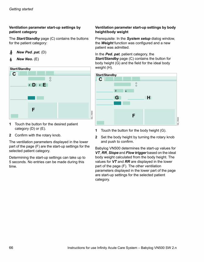
Getting started
66 Instructions for use Infinity Acute Care System – Babylog VN500 SW 2.n
Ventilation parameter start-up settings by patient category
The Start/Standby page (C) contains the buttons for the patient category:
1 Touch the button for the desired patient category (D) or (E).
2 Confirm with the rotary knob.
The ventilation parameters displayed in the lower part of the page (F) are the start-up settings for the selected patient category.
Determining the start-up settings can take up to 5 seconds. No entries can be made during this time.
Ventilation parameter start-up settings by body height/body weight
Prerequisite: In the System setup dialog window, the Weight function was configured and a new patient was admitted.
In the Ped. pat. patient category, the Start/Standby page (C) contains the button for body height (G) and the field for the ideal body weight (H).
1 Touch the button for the body height (G).
2 Set the body height by turning the rotary knob and push to confirm.
Babylog VN500 determines the start-up values for VT, RR, Slope and Flow trigger based on the ideal body weight calculated from the body height. The values for VT and RR are displayed in the lower part of the page (F). The other ventilation parameters displayed in the lower part of the page are start-up settings for the selected patient category.
New Ped. pat. (D)
New Neo. (E)
09
2_
VN
50
0
Start/Standby
C
F
D E
10
6_
VN
50
0
G
F
C
H
Start/Standby

Instructions for use Infinity Acute Care System – Babylog VN500 SW 2.n 67
Getting started
In the Neo. patient category, the patient's body weight is set directly. The Start/Standby page (C) contains the button for this start-up body weight (I).
1 Touch the button for the start-up body weight (I).
2 Using the rotary knob, set the start-up body weight and confirm the value.
The button for the current body weight (J) is displayed. After the patient has been admitted, the current body weight corresponds to the start-up body weight.
Babylog VN500 determines the start-up values for VT, RR, Slope and Flow trigger based on the start-up body weight. The values for VT and RR are displayed in the lower part of the page (F). The other ventilation parameters displayed in the lower part of the page are start-up settings for the selected patient category.
Determining the start-up settings can take up to 5 seconds. No entries can be made during this time.
Setting the body weight during ventilation
As a result of setting the ideal body weight in the Ped. pat. patient category or the current body weight in the Neo. patient category, measurements are displayed relative to the body weight, e.g. VT/kg BW.
Setting the body weight is only possible on the Start/Standby page during ventilation.
In the Ped. pat. patient category:
1 Touch the button for the ideal body weight.
2 Using the rotary knob, set the ideal body weight and confirm the value.
In the Neo. patient category:
1 Touch the button for the current body weight.
2 Using the rotary knob, set the current body weight and confirm the value.
Whenever the patient category has been changed
Check the breathing circuit, see chapter "Performing the breathing circuit check" on page 74.
Additional information
The configuration for the ventilation parameter start-up values by body height/body weight or by patient category is entered on the System setup >Ventilation > Start settings page. See chapter "Configuring start-up settings for the ventilation parameters" on page 171.
For information on configuring customized alarm limits, see chapter "Setting start-up values for alarm limits" on page 165.
For information on starting the therapy, see chapter "Starting therapy" on page 80.
31
9_
VN
50
0
Start/Standby
F
I J
C

Getting started
68 Instructions for use Infinity Acute Care System – Babylog VN500 SW 2.n
Selecting the breathing circuit and the breathing gas humidifier
The breathing circuit and the breathing gas humidifier can only be selected in standby mode.
1 Touch the Start/ Standby... button in the main menu bar.
2 Touch the Br. circuit/ Humidifier tab (A).
The page for selecting the breathing circuit and the breathing gas humidifier is displayed.
Selecting the breathing circuit from the selection list
3 Touch the button (B).
4 Select the breathing circuit used from the selection list.
5 Confirm with the rotary knob.
To help with the selection, the selected breathing circuit is displayed as a detailed representation (C) and also described as text (D).
Babylog VN500 automatically selects the appropriate humidification type based on the breathing circuit (E) selected. Some breathing circuits provide the selection of HME/Filter and None.
If the breathing circuit used is not included in the selection list
1 Touch the button (B).
2 Select Other from the selection list.
3 Confirm with the rotary knob.
4 Select the humidification type (E):– Active humid., exp. unheated – Active humid., exp. heated – HME/Filter – None
Touch the corresponding button.
Using the user-defined breathing circuit
Prerequisite: The User-defined hose settings function is enabled, see page 169.
1 Touch the button (B).
2 Select User-defined breathing circuit from the selection list.
3 Confirm with the rotary knob.
4 Select the humidification type (E).
5 Perform the breathing circuit check, see page 74.
6 Save the measured values for hose compliance and hose resistance, see page 76.
08
0
AB
CD
E
Start/Standby

Instructions for use Infinity Acute Care System – Babylog VN500 SW 2.n 69
Getting started
Infinity ID breathing circuits
When using Infinity ID breathing circuits, the connected hose type as well as the corresponding humidification type are set automatically.
If the message Infinity ID breathing circuit detected. is not displayed when an Infinity ID breathing circuit is connected, use a different Infinity ID breathing circuit. If the message is still not displayed, replace the Infinity ID neonatal expiratory valve or inspiratory valve.
Whenever the breathing circuit or the breathing gas humidifier have been changed
Check the breathing circuit, see "Performing the breathing circuit check" on page 74.

Getting started
70 Instructions for use Infinity Acute Care System – Babylog VN500 SW 2.n
Checking readiness for operation
The system check consists of the following elements:– Device check– Breathing circuit check– Battery check
The battery check must be performed during initial commissioning of the device. For further information on the battery check, see page 250 and page 254.
Safety information on the system check
Starting the system check
The system check is only possible in standby mode.
1 Touch the Start/ Standby... button in the main menu bar.
2 Touch the System check tab (A).
Babylog VN500 displays the following on the Overview page (B):– Last device check with date, time, and result (C)– Last breathing circuit check with date, time, and
the amount of leakage determined (D)– Battery check, result of the last battery check,
and date for the next battery check (E)
WARNING
Before using on the patient– Perform the device check. If a malfunction
is detected, do not operate the device! Patient hazard!
– Perform the breathing circuit check to ensure the pressure measurement accuracy. Otherwise the airway pressure may deviate from the set values.
10
1
AStart/Standby
BCD
E

Instructions for use Infinity Acute Care System – Babylog VN500 SW 2.n 71
Getting started
Performing the device check
The device check is only possible in standby mode.
Keeping the test lung ready
– Pediatric test lung (8409742) for the pediatric and neonatal breathing circuit
The test lung must only be inserted into the patient connector of the Y-piece after instruction by Babylog VN500.
Starting the device check
Prerequisites: The medication nebulizer is not connected. The System check page (A) is opened.
1 Touch the Device check tab (B).
Babylog VN500 displays the individual test steps in a list (C). The size of the list depends on the available applications.
2 Touch the Start button (D).
3 Confirm with the rotary knob.
Test steps in the device check
In the device check the following test steps are performed:– Auxiliary acoustical alarm (Check of the
auxiliary alarm/power failure alarm)There is no need for the user to test other parts of the alarm system, as they are tested in the self-test.
– Breathing circuit connection (visual inspection of breathing circuit)
– Inspect humidifier (visual inspection of breathing gas humidifier)
– CO2 sensor: Zero calibration– Neonatal flow sensor: Calibration– Neonatal flow sensor: Measurement– Test lung connection– Gas supply sensors: Calibration– O2 supply– Air supply– Gas supply unit (if the gas supply unit function
is activated)– Pressure sensor calibration valve– Expiratory valve (expiratory valve check)– Safety valve (safety function check)– O2 sensor: Calibration– Nebulizer (medication nebulizer control check)– Ejector (functional check)
10
2
C
BD
AStart/Standby

Getting started
72 Instructions for use Infinity Acute Care System – Babylog VN500 SW 2.n
Device check procedure
Babylog VN500 guides the user in the form of a question/answer dialog through the respective test step. The instruction field (E) displays the questions or instructions how to carry out the test steps.
The questions must be answered by touching the Yes (F) or No (G) buttons.
The Next test button (H) can be used to skip the test steps.
A test step is also skipped if the necessary prerequisites have not been met.
The test steps in the device check are displayed with the following symbols:
Repeating test steps in the device check
1 Touch the Repeat button (I).
2 Confirm with the rotary knob.
All test steps that have not yet been performed or that were unsuccessful are repeated.
Aborting the device check
1 Touch the Cancel button (J).
2 Confirm with the rotary knob.
The device check is also canceled when the Device check page is closed. The device check can be continued when the Device check page is opened again.
1 Touch the Repeat button (I).
2 Confirm with the rotary knob.
Test results
The test results obtained from the device check and the calibration and zero-checking values of the sensors remain stored until the next calibration, even if the device is switched off.
Incorrect test steps and remedies
Errors in the following safety-relevant test steps generate the medium-priority alarm message Device check failed:– Pressure sensor calibration valve– Expiratory valve– Safety valve
The alarm cannot be acknowledged. Do not start ventilation!
Errors in non-safety-relevant test steps or test steps that are not performed due to a prerequisite generate the low-priority alarm message Device check incomplete.
The alarm causes and their remedies are displayed on the Current alarms page.
10
2
Rotating symbol
Active test step
Green dot Correct result
Red dot Incorrect result
Colorless dot Test step not performed
GFE
Start/Standby
H
J I

Instructions for use Infinity Acute Care System – Babylog VN500 SW 2.n 73
Getting started
The following table shows the remedies for eliminating the errors during the device check:
Eliminate the causes of the error and repeat the test step.
If the test step still fails, contact DrägerService.
Test step Remedy
Auxiliary acoustical alarm
Contact DrägerService.
CO2 sensor: Zero calibration
Check whether the CO2 sensor is connected.Wait for the CO2 sensor to complete its three-minute warm-up phase.Check whether the CO2 sensor or the cuvette is soiled.
Neonatal flow sensor: Calibration
Clean the flow sensor.Seal the flow sensor during calibration.Check whether the flow sensor cable is connected.
Gas supply unit Check whether the gas connection to the device is kinked.Check whether the data cable is connected.If GS500 is running continuously, shut down and switch off Babylog VN500 (toggle switch to ).
Gas supply sensors: Calibration
Check whether the compressed gas hoses are connected.Shut down Babylog VN500 and switch it off (toggle switch to ).
O2 supply Check whether the O2 compressed gas hose is connected.
Air supply Check whether the Air compressed gas hose is connected.
Pressure sensor calibration valve
Connect the test lung. Check the breathing circuit for leaks.Check whether the compressed gas hoses are connected.Check whether the expiratory valve is properly engaged.
Expiratory valve Check whether the water trap is connected.Check whether the expiratory valve is properly engaged.
Safety valve Connect the test lung. Check the breathing circuit for leaks.Check whether the compressed gas hoses are connected.Check whether the expiratory valve is properly engaged.
O2 sensor: Calibration Check whether the compressed gas hoses are connected.
Nebulizer Prerequisite: The medication nebulizer is not connected.Check whether the compressed gas hoses are connected.
Ejector Check whether the compressed gas hoses are connected.

Getting started
74 Instructions for use Infinity Acute Care System – Babylog VN500 SW 2.n
Calibrating the gas supply sensors
The calibration of the gas supply sensors takes approximately 2 minutes. This test step must be performed every 3 months. If a test step does not need to be performed, it can be skipped by pressing No. The test step is still displayed as "successfully completed" (green dot).
If the test step is skipped with Next test, the test step is displayed as "not performed" (colorless dot).
If a complete calibration is necessary after 3 months and the test step is skipped with Next test, the test step is displayed as "failed" (red dot).
Calibrating the O2 sensor
The O2 sensor is calibrated during each device check. Regular calibration of the O2 sensor ensures the specified accuracy.
If the test step is skipped with Next test and the O2 sensor is not calibrated for 3 months, the accuracy of the O2 sensor will be reduced. In the parameter field for FiO2, a question mark will be displayed next to the measurement.
After calibration during the device check the sensor will work again with full accuracy. The measured value is displayed in the parameter field.
If the test step is skipped with Next test, the test step is displayed as "not performed" (colorless dot).
If Babylog VN500 requires the O2 sensor to be calibrated and the test step is still skipped with Next test, the test step is displayed as failed (red dot).
After the device check
The user is requested in field (E) to perform the check of the breathing circuit.
Confirm with Yes (F).
The page for the breathing circuit check is opened.
Performing the breathing circuit check
The check is only possible in standby mode.
The breathing circuit check must be performed after:– Device check– Changing the breathing circuit– Changing the breathing gas humidifier– Changing the patient category
Test steps during the breathing circuit check
The following test steps are performed:– Leakage of the breathing circuit– Compliance of the breathing circuit– Insp. Resistance– Exp. Resistance
CAUTION
If the quality of the oxygen from the central gas supply system is inadequate, calibrate the O2 sensor with an appropriate calibration gas (100 % O2). Otherwise this may result in an incorrect calibration.
10
2
GFE
Start/Standby
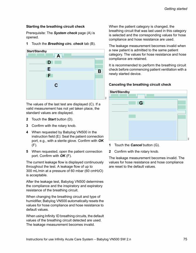
Instructions for use Infinity Acute Care System – Babylog VN500 SW 2.n 75
Getting started
Starting the breathing circuit check
Prerequisite: The System check page (A) is opened.
1 Touch the Breathing circ. check tab (B).
The values of the last test are displayed (C). If a valid measurement has not yet taken place, the standard values are displayed.
2 Touch the Start button (D).
3 Confirm with the rotary knob.
4 When requested by Babylog VN500 in the instruction field (E): Seal the patient connection port, e.g., with a sterile glove. Confirm with OK (F).
5 When requested, open the patient connection port. Confirm with OK (F).
The current leakage flow is displayed continuously throughout the test. A leakage flow of up to 300 mL/min at a pressure of 60 mbar (60 cmH2O) is acceptable.
After the leakage test, Babylog VN500 determines the compliance and the inspiratory and expiratory resistance of the breathing circuit.
When changing the breathing circuit and type of humidifier, Babylog VN500 automatically resets the values for hose compliance and hose resistance to default values.
When using Infinity ID breathing circuits, the default values of the breathing circuit detected are used. The leakage measurement becomes invalid.
When the patient category is changed, the breathing circuit that was last used in this category is selected and the corresponding values for hose compliance and hose resistance are used.
The leakage measurement becomes invalid when a new patient is admitted to the same patient category. The values for hose resistance and hose compliance are retained.
It is recommended to perform the breathing circuit check before commencing patient ventilation with a newly started device.
Canceling the breathing circuit check
1 Touch the Cancel button (G).
2 Confirm with the rotary knob.
The leakage measurement becomes invalid. The values for hose resistance and hose compliance are reset to the default values.
10
3
B
A
C
D
EF
Start/Standby
10
3
G
Start/Standby

Getting started
76 Instructions for use Infinity Acute Care System – Babylog VN500 SW 2.n
Repeating the breathing circuit check
If the breathing circuit is changed after the breathing circuit check, the humidification type or the patient category is changed, the breathing circuit check will have to be repeated.
The breathing circuit check is also necessary when using Infinity ID breathing circuits.
User-defined breathing circuit
Prerequisite: The user-defined breathing circuit has been selected, see "Using the user-defined breathing circuit" on page 68.
The values for hose resistance and hose compliance can be saved and are then available when that breathing circuit is selected again.
Touch the Save button (H).
Display of results of the breathing circuit check
Prerequisite: The System check page (A) is opened.
Touch the Check results tab (I).
The detailed results of the check are displayed:– Compliance [mL/mbar] (J)– Flow [L/min] (K)– Inspiratory resistance [mbar/L/s] (L)– Expiratory resistance [mbar/L/s] (M)
Display of the results of the system check on the Start/Standby page
After the system check, the results are displayed on the Start/Standby > Start/ Standby page.
– Result of device check (N)– Result of breathing circuit check (O)
36
9
H
Start/Standby
10
43
66
_V
N5
00
Start/Standby
J
A
I
KLM
Start/Standby
NO
Instructions for use Infinity Acute Care System – Babylog VN500 SW 2.n 77
Getting started
Checking the switch-over to battery operation
1 Unplug the power plug.
If there is a PS500 power supply unit present, the device switches over to the PS500 without interruption. If there is no PS500 present or the PS500 is discharged, the device switches over to the internal battery without interruption. The Battery activated alarm is displayed.
2 Plug the power plug back in.
The device switches back to mains operation. The Battery activated alarm message goes out.
Checking the alarm signaling
When the system check has been successfully completed, the device is ready for operation. The alarm signaling can be checked additionally.
The description of alarm signaling can be found in chapter "Alarms." Additional information on alarm criteria can be found in chapter "Alarm – Cause – Remedy."
High-priority alarm message
1 Start ventilation.
2 After 2 minutes set the upper alarm limit for MVe to a value below the measured value of MVe.
The MV high alarm is triggered.
Medium-priority alarm message
1 Start ventilation.
2 Switch on the additional setting Volume Guarantee.
3 Reduce the upper alarm limit for Paw until the VT not reached, Pmax active alarm is triggered.
Low-priority alarm message
1 Start ventilation.
2 In the Special maneuvers > Maneuvers dialog window, touch and hold the Man. insp./hold button until the Inspiratory hold interrupted alarm is triggered.
Checking alarm limits
The alarm limits for a settable alarm can be checked by setting the alarm limits appropriately. When the alarm limit is exceeded, the corresponding alarm is triggered.
Additional information on setting alarm limits can be found in chapter "Setting alarm limits" on page 128.
Test of the acoustic alarm system
The acoustic alarm system need not be tested by the user. The device tests the functions of the acoustic alarm system automatically during the device check.

Getting started
78 Instructions for use Infinity Acute Care System – Babylog VN500 SW 2.n
Selecting the Tube or NIV application mode
Babylog VN500 can switch between non-invasive ventilation and tube ventilation.
The application mode can only be selected in standby mode.
1 Touch the Start/ Standby... button in the main menu bar.
2 Touch the Tube/NIV tab (A).
3 Touch the Tube (B) or NIV button (C).
4 Confirm with the rotary knob.
Observe the information on changing the application mode!
Additional information
For information on using the NIV application mode for non-invasive ventilation, see "NIV – Non-invasive ventilation" on page 92.
Setting parameters for the tube
The inner diameter of the tube and the tube type can be entered for the following functions:– Display of Ptrach, independent of ATC– Measurement of patient resistance Rpat and
the index C20/Cdyn
If the inner diameter of the tube and the tube type are entered, the measured value Rpat corresponds to the patient resistance. Rpat and C20/Cdyn are only displayed correctly if the inner diameter of the tube and the tube type are entered correctly. The measured value R always corresponds to the total resistance.
Prerequisite: The Tube/NIV page (A) is opened. The Tube application mode has been selected.
Activating or deactivating the calculation of tracheal pressure
1 Touch the appropriate button (B).
2 Confirm with the rotary knob.
If ATC is switched off, the calculation of tracheal pressure is always deactivated when a new patient is admitted.
113
CAUTION
Application mode NIV must not be activated with intubated patients.
WARNING
Alarm limits and ventilation settings must be checked or set again in order to ensure complete monitoring of ventilation after changing from NIV application mode to Tube application mode.
AB C
Start/Standby
113
A
CD
Start/Standby
B
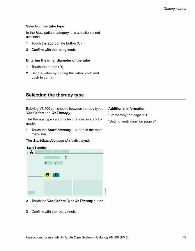
Instructions for use Infinity Acute Care System – Babylog VN500 SW 2.n 79
Getting started
Selecting the tube type
In the Neo. patient category, this selection is not available.
1 Touch the appropriate button (C).
2 Confirm with the rotary knob.
Entering the inner diameter of the tube
1 Touch the button (D).
2 Set the value by turning the rotary knob and push to confirm.
Selecting the therapy type
Babylog VN500 can choose between therapy types Ventilation and O2 Therapy.
The therapy type can only be changed in standby mode.
1 Touch the Start/ Standby... button in the main menu bar.
The Start/Standby page (A) is displayed.
2 Touch the Ventilation (B) or O2 Therapy button (C).
3 Confirm with the rotary knob.
Additional information
"O2 therapy" on page 111.
"Setting ventilation" on page 84.
12
6_
VN
50
0
A
B C
Start/Standby

Getting started
80 Instructions for use Infinity Acute Care System – Babylog VN500 SW 2.n
Starting therapy
Before using on the patient
Carry out a system check to ensure that Babylog VN500 is operating correctly, see page 70.
Check the therapy settings: Set the alarm limits, see page 128. Set the ventilation modes and ventilation parameters, see "Setting ventilation" on page 84.
Starting ventilation or O2 therapy
1 Touch the Start/ Standby... button in the main menu bar.
The Start/Standby page (A) is displayed.
2 Touch the Start ventilation button (B) and confirm with the rotary knob.
Babylog VN500 starts the therapy with the set ventilation parameters. The main page for ventilation or O2 therapy is displayed.
Additional information
The page for the ventilation settings can be opened with the Ventilation settings... button (C).
36
7_
VN
50
0
Start/Standby
C
BA

Instructions for use Infinity Acute Care System – Babylog VN500 SW 2.n 81
Getting started
Displaying the status of accessories
1 Touch the Start/ Standby... button in the main menu bar.
2 Touch the Accessory status tab (A).
In field (B) Babylog VN500 displays the time until it is recommended to exchange the accessories.
Sterilization of the expiratory valve or inspiratory valve may gradually impair the operation of RFID transmission. This may mean that Infinity ID breathing circuit functions may not work or may no longer work reliably. The status of the Infinity ID accessories is not displayed.
Additional information
The time for the exchange interval can be configured on the System setup > System status > Exchange intervals page. See "System status" on page 181.
36
8
Start/Standby
B
A

82 Instructions for use Infinity Acute Care System – Babylog VN500 SW 2.n
This page has been left blank intentionally.

Instructions for use Infinity Acute Care System – Babylog VN500 SW 2.n 83
Operation
Operation
Setting ventilation . . . . . . . . . . . . . . . . . . . . . 84
Overview. . . . . . . . . . . . . . . . . . . . . . . . . . . . . . 84Opening the Ventilation settings dialog window . . . . . . . . . . . . . . . . . . . . . . . . . . . . . . . 84Selecting ventilation modes . . . . . . . . . . . . . . . 84Setting ventilation parameters . . . . . . . . . . . . . 85General settings for ventilation . . . . . . . . . . . . . 86Additional settings for ventilation . . . . . . . . . . . 89
NIV – Non-invasive ventilation . . . . . . . . . . . 92
Overview. . . . . . . . . . . . . . . . . . . . . . . . . . . . . . 92Safety information when using NIV . . . . . . . . . 92Selecting NIV application mode . . . . . . . . . . . . 93Starting NIV ventilation . . . . . . . . . . . . . . . . . . . 94Setting ventilation parameters for NIV . . . . . . . 94Monitoring during NIV. . . . . . . . . . . . . . . . . . . . 94
Displaying curves and measured values . . . 95
Overview. . . . . . . . . . . . . . . . . . . . . . . . . . . . . . 95Changing the screen view . . . . . . . . . . . . . . . . 95Changing the display of monitoring fields. . . . . 95Evaluating loops . . . . . . . . . . . . . . . . . . . . . . . . 97Freezing waveforms . . . . . . . . . . . . . . . . . . . . . 97Smart Pulmonary View . . . . . . . . . . . . . . . . . . . 98
Help . . . . . . . . . . . . . . . . . . . . . . . . . . . . . . . . . 99
Maneuvers. . . . . . . . . . . . . . . . . . . . . . . . . . . . 100
Overview. . . . . . . . . . . . . . . . . . . . . . . . . . . . . . 100Manual inspiration – Manual inspiration/hold . . 100Oxygen enrichment for suction maneuver . . . . 101
Medication nebulization. . . . . . . . . . . . . . . . . 103
Safety information on medication nebulization . . . . . . . . . . . . . . . . . . . . . . . . . . . 103Preparing the pneumatic medication nebulizer . . . . . . . . . . . . . . . . . . . . . . . . . . . . . . 104Installing the medication nebulizer into the breathing circuit . . . . . . . . . . . . . . . . . . . . . . . . 104Switching on medication nebulization. . . . . . . . 106Aborting medication nebulization . . . . . . . . . . . 108Required steps after medication nebulization. . 108Fitting the Aeroneb nebulizer . . . . . . . . . . . . . . 109
GS500 gas supply unit . . . . . . . . . . . . . . . . . 110
Installing the bacterial filter . . . . . . . . . . . . . . . 110Using the gas supply unit . . . . . . . . . . . . . . . . 110
O2 therapy . . . . . . . . . . . . . . . . . . . . . . . . . . . 111
Safety information for O2 therapy . . . . . . . . . . 111Preparing O2 therapy . . . . . . . . . . . . . . . . . . . 111Switching on O2 therapy . . . . . . . . . . . . . . . . . 112Setting FiO2 and flow for O2 therapy. . . . . . . . 113Switching off O2 therapy . . . . . . . . . . . . . . . . . 113
Standby mode . . . . . . . . . . . . . . . . . . . . . . . . 114
Activating standby mode . . . . . . . . . . . . . . . . . 114Continuing the therapy . . . . . . . . . . . . . . . . . . 115
Ending operation . . . . . . . . . . . . . . . . . . . . . . 116
Disconnecting the device from the mains voltage . . . . . . . . . . . . . . . . . . . . . . . . . . . . . . 117
Storing Babylog VN500. . . . . . . . . . . . . . . . . 117
Mains power supply / DC power supply . . . 118
Components and terms . . . . . . . . . . . . . . . . . . 118Use of power supplies . . . . . . . . . . . . . . . . . . . 118Battery operation . . . . . . . . . . . . . . . . . . . . . . . 119Battery charging . . . . . . . . . . . . . . . . . . . . . . . 119Care and maintenance of the batteries . . . . . . 120
Intrahospital patient transport . . . . . . . . . . . 121
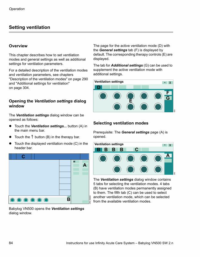
Operation
84 Instructions for use Infinity Acute Care System – Babylog VN500 SW 2.n
Setting ventilation
Overview
This chapter describes how to set ventilation modes and general settings as well as additional settings for ventilation parameters.
For a detailed description of the ventilation modes and ventilation parameters, see chapters "Description of the ventilation modes" on page 290 and "Additional settings for ventilation" on page 304.
Opening the Ventilation settings dialog window
The Ventilation settings dialog window can be opened as follows:
Touch the Ventilation settings... button (A) in the main menu bar.
Touch the button (B) in the therapy bar.
Touch the displayed ventilation mode (C) in the header bar.
Babylog VN500 opens the Ventilation settings dialog window.
The page for the active ventilation mode (D) with the General settings tab (F) is displayed by default. The corresponding therapy controls (E) are displayed.
The tab for Additional settings (G) can be used to supplement the active ventilation mode with additional settings.
Selecting ventilation modes
Prerequisite: The General settings page (A) is opened.
The Ventilation settings dialog window contains 5 tabs for selecting the ventilation modes. 4 tabs (B) have ventilation modes permanently assigned to them. The fifth tab (C) can be used to select another ventilation mode, which can be selected from the available ventilation modes.
07
8_
VN
50
0
1 2 3
B
C
A
08
30
83
EG
DF
Ventilation settings
BVentilation settings
CA
B B B

Instructions for use Infinity Acute Care System – Babylog VN500 SW 2.n 85
Operation
The following 4 ventilation modes are preset at the factory:– PC-CMV– PC-AC– PC-SIMV– PC-PSV
For information on changing the assignment of ventilation modes, see "Configuring start-up settings for the ventilation modes" on page 170.
Selecting an additional ventilation mode in the dialog window
1 Touch the Other modes tab (D).
All the available ventilation modes (E) are displayed.
2 Touch the button for the corresponding ventilation mode. The color of the tab (D) turns yellow.
3 Confirm with the rotary knob.
The additional ventilation mode is displayed in the fifth tab (C). The ventilation mode is active.
Changing the ventilation mode
1 Touch the corresponding tab, e.g., (F). The color of the tab turns yellow.
2 Preset the ventilation parameters if necessary.
3 Confirm with the rotary knob. The color of the tab turns dark green.
The ventilation mode is active. The settings are applied to the patient.
Setting ventilation parameters
Prerequisite: The General settings page (A) is opened.
1 Touch the corresponding therapy control, e.g., (B).
2 Set the value by turning the rotary knob and push to confirm.
The additional ventilation parameters derived from the ventilation parameter are calculated by Babylog VN500 and displayed in the setting assistance field (C).
Information is displayed in the message field (D), e.g., when the setting limit of a parameter has been reached.
Setting ventilation parameters in the therapy bar
The ventilation parameters of the active ventilation mode can also be set with the therapy controls in the therapy bar (E).
17
00
77
Ventilation settings
DC
E
FVentilation settings
13
10
78
B
C
DVentilation settings
A
E

Operation
86 Instructions for use Infinity Acute Care System – Babylog VN500 SW 2.n
Additional information
"Exceeding the set limit of a ventilation parameter" on page 39.
"Direct setting of ventilation parameters (QuickSet)" on page 39.
"Linked setting of ventilation parameters" on page 40.
General settings for ventilation
The general settings for the ventilation parameters are listed in the following tables:– Pressure-controlled ventilation modes– Spontaneous breathing support
WARNING
If flow measurement is deactivated for SPN-CPAP, use a separate monitoring device.
CAUTION
Only remove the water trap of the expiratory valve briefly during ventilation. Otherwise, ventilation will be impaired.

Instructions for use Infinity Acute Care System – Babylog VN500 SW 2.n 87
Operation
Pressure-controlled ventilation modes
Ventilation parameters
Ventilation mode
PC-SIMV PC-AC PC-CMV PC-APRV PC-MMV PC-PSV PC-HFO
FiO2 X X X X X X X
VT X1)
1) if VG is switched on
X1) X1) X X1)
Ti X X X X
RR X X X X X
Slope or Insp. flow2)
2) depending on the configuration of Slope adjustment
X X X X X X
Pmax X3)
3) if Pmax/Paw high autoset is activated and ATC or Apnea Ventilation or VG is switched on
X3) X3) X3) X3) X3)
Pinsp X4)
4) if VG is switched off
X4) X4) X4)
PEEP X X X X X
Psupp X X
Timax X5)
5) in the Neo. patient category in the Tube application mode, or in the Ped. pat. patient category in the NIV application mode
Thigh X
Tlow X6)
6) if AutoRelease is switched off
Phigh X
Plow X
Tlow max X7)
7) If AutoRelease is switched on
Exp. term. X7)
I:Ehf X
fhf X
Ampl hf X
MAPhf X
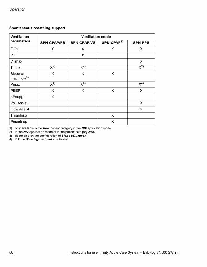
Operation
88 Instructions for use Infinity Acute Care System – Babylog VN500 SW 2.n
Spontaneous breathing support
Ventilation parameters
Ventilation mode
SPN-CPAP/PS SPN-CPAP/VS SPN-CPAP1)
1) only available in the Neo. patient category in the NIV application mode
SPN-PPS
FiO2 X X X X
VT X
VTmax X
Timax X2)
2) in the NIV application mode or in the patient category Neo.
X2) X2)
Slope or Insp. flow3)
3) depending on the configuration of Slope adjustment
X X X
Pmax X4)
4) if Pmax/Paw high autoset is activated
X4) X4)
PEEP X X X X
Psupp X
Vol. Assist X
Flow Assist X
TmanInsp X
PmanInsp X

Instructions for use Infinity Acute Care System – Babylog VN500 SW 2.n 89
Operation
Additional settings for ventilation
Overview of possible supplementary settings
The ventilation modes can be combined with additional settings to optimize ventilation. The table shows the possible additional settings for the respective ventilation mode.
Setting the supplementary settings
Prerequisite: The page with the active ventilation mode is open.
1 Touch the Additional settings tab (A).
The additional settings of the active ventilation mode are displayed.
2 Touch the tab of the respective additional setting (B).
The page for setting the corresponding parameters is opened.
3 Use the buttons (C) to activate or deactivate the additional setting.
4 Touch the corresponding therapy control (D).
5 Set the value by turning the rotary knob and push to confirm.
Ventilation mode
Additional settings
Apnea Ventilation
Trigger Sigh ATC Volume Guarantee
Auto Release
HFO-Sigh
Volume Guarantee
(HFO)
PC-CMV X X X
PC-AC X X X X
PC-SIMV X X X X X
PC-PSV X X X X
PC-MMV X X X X
PC-APRV X X X
SPN-CPAP/PS X X X
SPN-CPAP/VS X X X
SPN-PPS X X X
PC-HFO X X
08
4
AB
Ventilation settings
09
8
C
D
Ventilation settings
C
D D
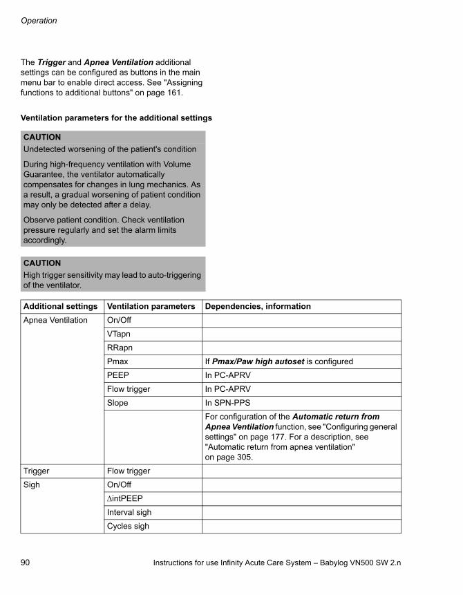
Operation
90 Instructions for use Infinity Acute Care System – Babylog VN500 SW 2.n
The Trigger and Apnea Ventilation additional settings can be configured as buttons in the main menu bar to enable direct access. See "Assigning functions to additional buttons" on page 161.
Ventilation parameters for the additional settings
CAUTION
Undetected worsening of the patient's condition
During high-frequency ventilation with Volume Guarantee, the ventilator automatically compensates for changes in lung mechanics. As a result, a gradual worsening of patient condition may only be detected after a delay.
Observe patient condition. Check ventilation pressure regularly and set the alarm limits accordingly.
CAUTION
High trigger sensitivity may lead to auto-triggering of the ventilator.
Additional settings Ventilation parameters Dependencies, information
Apnea Ventilation On/Off
VTapn
RRapn
Pmax If Pmax/Paw high autoset is configured
PEEP In PC-APRV
Flow trigger In PC-APRV
Slope In SPN-PPS
For configuration of the Automatic return from Apnea Ventilation function, see "Configuring general settings" on page 177. For a description, see "Automatic return from apnea ventilation" on page 305.
Trigger Flow trigger
Sigh On/Off
intPEEP
Interval sigh
Cycles sigh

Instructions for use Infinity Acute Care System – Babylog VN500 SW 2.n 91
Operation
Additional information
For a detailed description of the additional settings, see chapter "Additional settings for ventilation" on page 304.
ATC On/Off See chapter "Configuration" on page 155.
Tube type (ET/Trach.) Only available in the Ped. pat. patient category
Tube Ø Inner diameter of the tube
Compens. Degree of compensation:Compens. = 100 % – airway pressure regulation to trachea level
Pmax If Pmax/Paw high autoset is configured
Volume Guarantee On/Off See chapter "Configuration" on page 155.
VT
Pmax If Pmax/Paw high autoset is configured
Pinsp If VG is switched off
AutoRelease On/Off
Exp. term.
Tlow If AutoRelease is switched off
Tlow max If AutoRelease is switched on
HFO-Sigh Psigh
RRsigh
Tisigh
Slopesigh If Slope is configured, see page 177
Volume Guarantee (HFO)
On/Off
VThf
Ampl hf Set the amplitude before switching off the Volume Guarantee (HFO)
Ampl hf max
Additional settings Ventilation parameters Dependencies, information

Operation
92 Instructions for use Infinity Acute Care System – Babylog VN500 SW 2.n
NIV – Non-invasive ventilation
Overview
Babylog VN500 can be used for the ventilation of intubated patients (application mode Tube) and for non-invasive ventilation (application mode NIV).
This chapter describes the use of non-invasive ventilation in the NIV application mode.
The following ventilation modes can be selected in the NIV application mode:
When the PC-HFO ventilation mode is set and the NIV application mode is activated, Babylog VN500 automatically switches the ventilation mode:– in the Ped. pat. patient category to the SPN-
CPAP/PS ventilation mode– in the Neo. patient category to the SPN-CPAP
ventilation mode
Safety information when using NIV
If automatic tube compensation (ATC) is activated in Tube application mode, it becomes ineffective when switching to NIV application mode.
Ventilation mode Patient category
Ped. pat. Neo.
PC-CMV X X
PC-AC X
PC-SIMV X
PC-PSV X
PC-MMV X
PC-APRV X
SPN-CPAP X
SPN-CPAP/PS X
SPN-CPAP/VS X
SPN-PPS X
CAUTION
Application mode NIV must not be activated with intubated patients.
CAUTION
Use of masks increases the dead space. Observe the mask manufacturer's instructions!
NOTE
Use suitable masks and prongs. Otherwise excessive leakages may occur.
WARNING
Avoid high airway pressures. Danger of aspiration!
WARNING
Alarm limits and ventilation settings must be checked or set again in order to ensure complete monitoring of ventilation after changing from NIV application mode to Tube application mode.

Instructions for use Infinity Acute Care System – Babylog VN500 SW 2.n 93
Operation
Selecting NIV application mode
The application mode can only be selected in standby mode.
1 Touch the Start/ Standby... button in the main menu bar.
Babylog VN500 opens the Start/Standby dialog window. The Start/Standby page is displayed by default.
2 Touch the Standby button and confirm with the rotary knob.
Babylog VN500 is in standby mode.
3 Touch the Tube/NIV tab (A).
4 Touch the NIV button (B) and confirm with the rotary knob.
Babylog VN500 is in the NIV application mode. Babylog VN500 displays the symbol in the header bar
In the Neo. patient category, flow monitoring is deactivated.
Limiting the inspiratory flow in the Neo. patient category
In the Neo. patient category the inspiratory flow can be limited with the Flow max setting. The base flow and the nebulizer flow (if active) are not affected by this setting. If the NIV application mode is selected, the setting is reset to the maximum value.
To limit the maximum flow:
Touch the Flow max button (C). Set the value by turning the rotary knob and push to confirm.
36
5
Start/Standby
AB
C

Operation
94 Instructions for use Infinity Acute Care System – Babylog VN500 SW 2.n
Starting NIV ventilation
Prerequisite: The Start/Standby dialog window is opened.
1 Touch the Start/Standby tab (A).
2 Touch the Start ventilation button (B) and confirm with the rotary knob.
Babylog VN500 starts the therapy with the set ventilation parameters. The main screen for ventilation is displayed.
Setting ventilation parameters for NIV
Set the ventilation parameters as described under "Setting ventilation parameters" on page 85.
Therapy control Timax
The therapy control Timax (A) limits the maximum duration of supported breaths (Pressure Support, Volume Support, PPS) because the inspiratory termination criterion may be ineffective with very high leakages.
Set the value for Timax by turning the rotary knob and push to confirm.
Therapy control TmanInsp and PmanInsp
Prerequisite: The Neo. patient category and the SPN-CPAP ventilation mode are set.
During manual inspiration, the duration of the mandatory breath is determined by the TmanInsp therapy control (B).
During manual inspiration, the pressure of the mandatory breath is determined by the PmanInsp therapy control (C).
Set and confirm the relevant values using the rotary knob.
Monitoring during NIV
Use additional monitoring, e.g., external SpO2, if necessary.
A delay time Tdisconnect between 0 and 60 seconds can be set for the lower alarm limit for the airway pressure.
Additional information
"Setting alarm limits" on page 128.
36
7_
VN
50
01
05
Start/Standby
AB
A
Ventilation settings
33
9
Ventilation settings
B
C

Instructions for use Infinity Acute Care System – Babylog VN500 SW 2.n 95
Operation
Displaying curves and measured values
Overview
This chapter describes how curves and measured values are displayed on the main screen as well as how to change the screen views during operation.
Changing the screen view
Babylog VN500 displays a preconfigured view on the main screen.Three hospital-defined views can be created in the System setup dialog window.
Displaying other views
Touch the Views... button in the main menu bar.
The screen displays the second view .
Touch the Views... button.
The screen displays the third view .
Changing the display of monitoring fields
The parameters can be displayed in parameter fields (A) and in the curve field (B).
The fields can be standard or double in size. The information that can be displayed depends on the size of the fields:
Parameter fields
Curve fields
115
_V
N5
00
1 2 3
1 2 3
1 2 3
1 2 3
1 2 3
B
A
Standard size Single parameter
Two parameters
Short trend for measured values
Short trend for set values
Double size Single parameter
Parameter group
Loop
Short trend for measured values
Short trend for set values
Standard size Single curve
Trend for measured values
Trend for set values
Tabular trend
Multi-trend
Alarm history
Double size Single curve
Single loop
Double loops
Trend for measured values
Trend for set values
Tabular trend
Multi-trend
Alarm history
Lung display (Smart Pulmonary View)

Operation
96 Instructions for use Infinity Acute Care System – Babylog VN500 SW 2.n
Selecting the display of parameter fields
1 Touch the parameter field.
The selected parameter field is highlighted. Babylog VN500 opens the dialog for the contents of the parameter field.
Selecting the field size
2 Touch the 1x button (C) for standard size or 2x (D) for double size.
Selecting the display format
3 Touch the button (E).
The selection list for the display of parameters is displayed according to the selected size of the parameter field.
4 Select the display format and confirm with the rotary knob.
Selecting the parameter
5 Touch the button (F).
The selection list for the displayable parameters is displayed.
6 Select the parameter and confirm it with the rotary knob.
Closing the dialog
7 Touch the button X. The dialog is closed.
Selecting the display of curve fields
1 Touch the curve field.
The selected curve field is highlighted. Babylog VN500 opens the dialog for the contents of the curve field.
2 Proceed as described under "Selecting the display of parameter fields".
Additional information
"Configuring the screen view" on page 158.
"Factory-set screen views" on page 335.
10
7
E
F
C D
Content

Instructions for use Infinity Acute Care System – Babylog VN500 SW 2.n 97
Operation
Evaluating loops
Displaying a reference loop
Touch the Ref. button (A).
A loop is recorded and displayed as a reference loop.
The date and the time of the loop appear beside the button (A). The reference loop is drawn in black. The reference loop remains displayed until the Ref. button (A) is touched again.
Recording the current loop in order to freeze, display and save it afterwards
Touch the Capture loop button (B).
The current loop is frozen. The loops are drawn in blue. After "freezing", a cursor (C) is displayed which can be moved with the rotary knob. The respective values are displayed (D).
Recording up to 10 loops of mandatory or spontaneous breaths
1 Touch the Draw button (E).
2 Set how many loops should be recorded with the rotary knob and push to confirm.
The set number is displayed in the button.
Additional information
A grid only appears if loops are displayed in the complete curve field.
Freezing waveforms
The Freeze waveforms function can be configured as a button in the main menu bar to enable direct access. See "Assigning functions to additional buttons" on page 161.
Touch the Freeze waveforms button in the main menu bar.
The current curves are immediately frozen. The cursor (A) displays the time of "freezing" and the value at the cursor position.
To display a measured value at a certain moment in time:
Position the cursor on the time with the rotary knob.
The measured value or the measured value pair are displayed above the curve.
To cancel the freezing waveforms function:
Touch the Freeze waveforms button again in the main menu bar.
112
500.0
450.0
400.0
350.0
300.0
250.0
200.0
150.0
100.0
50.0
0.0-5.0 0.0 5.0 10.0 15.0 20.0 25.0 30.0
E
C
D
A
B
14
5
A
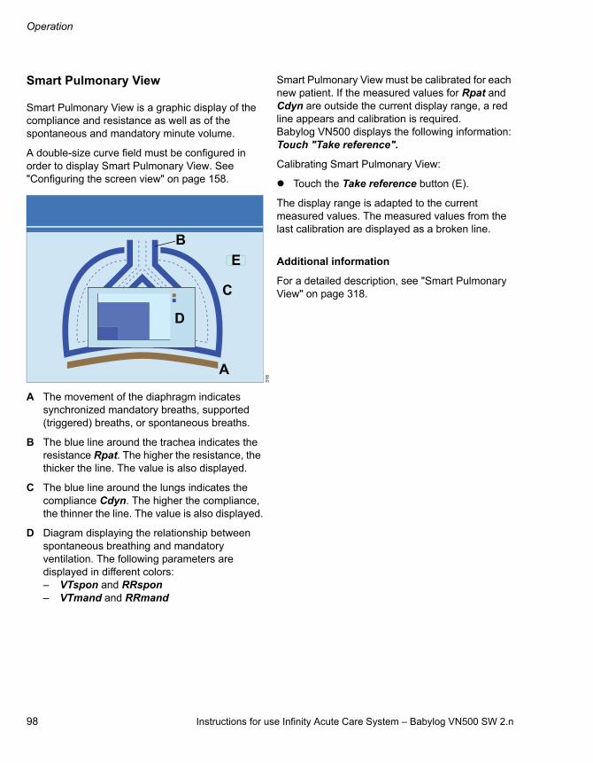
Operation
98 Instructions for use Infinity Acute Care System – Babylog VN500 SW 2.n
Smart Pulmonary View
Smart Pulmonary View is a graphic display of the compliance and resistance as well as of the spontaneous and mandatory minute volume.
A double-size curve field must be configured in order to display Smart Pulmonary View. See "Configuring the screen view" on page 158.
A The movement of the diaphragm indicates synchronized mandatory breaths, supported (triggered) breaths, or spontaneous breaths.
B The blue line around the trachea indicates the resistance Rpat. The higher the resistance, the thicker the line. The value is also displayed.
C The blue line around the lungs indicates the compliance Cdyn. The higher the compliance, the thinner the line. The value is also displayed.
D Diagram displaying the relationship between spontaneous breathing and mandatory ventilation. The following parameters are displayed in different colors:– VTspon and RRspon– VTmand and RRmand
Smart Pulmonary View must be calibrated for each new patient. If the measured values for Rpat and Cdyn are outside the current display range, a red line appears and calibration is required. Babylog VN500 displays the following information:Touch "Take reference".
Calibrating Smart Pulmonary View:
Touch the Take reference button (E).
The display range is adapted to the current measured values. The measured values from the last calibration are displayed as a broken line.
Additional information
For a detailed description, see "Smart Pulmonary View" on page 318.
31
6
D
A
B
C
E

Instructions for use Infinity Acute Care System – Babylog VN500 SW 2.n 99
Operation
Help
The Help function can be configured as a button in the main menu bar to enable direct access. See "Assigning functions to additional buttons" on page 161.
Opening Help
Touch the Help... button in the main menu bar.
The following buttons are available in the Help dialog window:– Home (A) to open the start page– (B) to scroll back– (C) to scroll forward– Content (D) to open the table of contents– Index (E) to open the index
Touch the appropriate button.
Closing Help
Touch the button (F).
Opening Help in the dialog window
The Help function can also be opened in the following dialog windows:– Ventilation settings – Special maneuvers > Nebulization – Special maneuvers > Maneuvers
Touch the button (G) in the dialog window.
The appropriate section of the Help is displayed.
Closing Help
Touch the buttons (G) or (H) in the dialog window.
WARNING
Risk of operating error
The Help function is not a substitute for the instructions for use. The instructions for use must be observed to ensure safe operation.
31
8
FHelp
A B C D E
17
1
G HVentilation settings
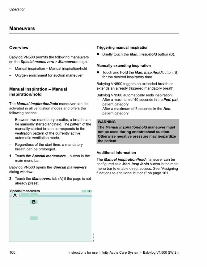
Operation
100 Instructions for use Infinity Acute Care System – Babylog VN500 SW 2.n
Maneuvers
Overview
Babylog VN500 permits the following maneuvers on the Special maneuvers > Maneuvers page:
– Manual inspiration – Manual inspiration/hold
– Oxygen enrichment for suction maneuver
Manual inspiration – Manual inspiration/hold
The Manual inspiration/hold maneuver can be activated in all ventilation modes and offers the following options:
– Between two mandatory breaths, a breath can be manually started and held. The pattern of the manually started breath corresponds to the ventilation pattern of the currently active automatic ventilation mode.
– Regardless of the start time, a mandatory breath can be prolonged.
1 Touch the Special maneuvers... button in the main menu bar.
Babylog VN500 opens the Special maneuvers dialog window.
2 Touch the Maneuvers tab (A) if the page is not already preset.
Triggering manual inspiration
Briefly touch the Man. insp./hold button (B).
Manually extending inspiration
Touch and hold the Man. insp./hold button (B) for the desired inspiratory time.
Babylog VN500 triggers an extended breath or extends an already triggered mandatory breath.
Babylog VN500 automatically ends inspiration:– After a maximum of 40 seconds in the Ped. pat.
patient category– After a maximum of 5 seconds in the Neo.
patient category
Additional information
The Manual inspiration/hold maneuver can be configured as a Man. insp./hold button in the main menu bar to enable direct access. See "Assigning functions to additional buttons" on page 161.
08
1_
VN
50
0
BA
Special maneuvers
WARNING
The Manual inspiration/hold maneuver must not be used during endotracheal suction. Otherwise negative pressure may jeopardize the patient.

Instructions for use Infinity Acute Care System – Babylog VN500 SW 2.n 101
Operation
Oxygen enrichment for suction maneuver
Overview
To avoid hypoxia during endotracheal suction, Babylog VN500 offers a function for oxygen enrichment.
The O2 concentration is increased to the current inspiratory O2 concentration, multiplied by a factor. The factor can be configured, see page 177.
After oxygen enrichment is started, Babylog VN500 ventilates the patient with an increased O2 concentration for an initial oxygen enrichment phase of 180 seconds max. During this time, Babylog VN500 waits for a disconnection.
When the device is disconnected for suction, Babylog VN500 interrupts ventilation. During the suction phase, the acoustic alarms are suppressed so that the suction maneuver is not disturbed.
After suction and automatically recognized reconnection, Babylog VN500 delivers an increased O2 concentration for the final oxygen enrichment phase of 120 seconds.
During suction and for 120 seconds afterwards, the lower alarm limit for the minute volume is switched off.
Initial and final oxygen enrichment are only possible with a fully functioning flow sensor and if flow monitoring is switched on!
Before suction
1 Touch the Special maneuvers... button in the main menu bar.
Babylog VN500 opens the Special maneuvers dialog window.
2 Touch the Maneuvers tab (A) if the page is not already preset.
3 Touch the O2 suction button (B) and confirm with the rotary knob.
The oxygen enrichment program is started.
Babylog VN500 ventilates in the set ventilation mode with an increased O2 concentration:1 to 2 times the current FiO2 concentration.
If PEEP is not set to more than 4 mbar (4 cmH2O), a PEEP of 4 mbar (4 cmH2O) will be applied automatically. This PEEP allows Babylog VN500 to detect disconnection. The other ventilation parameters remain unaffected.
WARNING
Select an appropriate suction catheter for suction. Otherwise this may result in a too high negative pressure.
WARNING
Risk of patient injury during suction in a closed breathing circuit
Using closed suction systems produces negative pressure in the patient's airways. This leads to impaired ventilation and therefore to impaired gas exchange.
Observe patient condition.
08
1_
VN
50
0
B
ASpecial maneuvers

Operation
102 Instructions for use Infinity Acute Care System – Babylog VN500 SW 2.n
Screen display:
The field (C) in the header bar continuously displays the initial oxygen enrichment phase with the remaining time in seconds.
Initial oxygen enrichment lasts for a maximum of 180 seconds. During this time Babylog VN500 waits for a disconnection for suction. Babylog VN500 terminates the oxygen enrichment if there is no disconnection after the 180 seconds have elapsed.
After disconnection for suction, Babylog VN500 delivers a minimal flow for the duration of disconnection in order to detect automatically the end of the disconnection phase. 120 seconds are available for suctioning. In the header bar, the disconnection phase with the remaining time available for suction is displayed continuously in seconds (C).
Automatic termination of oxygen enrichment
If there is no reconnection when the time available (120 seconds) has elapsed, the oxygen enrichment is terminated. All alarms are immediately active again. Babylog VN500 continues to ventilate immediately in the set ventilation mode.
After reconnection
After reconnection, Babylog VN500 continues ventilating in the set ventilation mode, except that for 120 seconds an increased O2 concentration will continue to be delivered for final oxygen enrichment.
In the header bar, the remaining time available for the final oxygen enrichment phase is displayed continuously in seconds.
Terminating oxygen enrichment prematurely
Touch the O2 suction button again and confirm with the rotary knob.
Additional information
The suction maneuver can be configured as a O2 suction button in the main menu bar to enable direct access. See "Assigning functions to additional buttons" on page 161.
07
8_
VN
50
0
1 2 3
C

Instructions for use Infinity Acute Care System – Babylog VN500 SW 2.n 103
Operation
Medication nebulization
Safety information on medication nebulization
Failure of the Air supply
If the Air supply fails during medication nebulization, the medication nebulizer will continue to operate with 100 Vol% O2. In this case, deviations in the inspiratory O2 concentration are possible.
WARNING
Risk of fire
The flow sensor can ignite medications or other substances based on highly flammable substances.– Do not nebulize medications or other
substances that are easily flammable or spray them into the device.
– Do not use substances containing alcohol.– Do not allow flammable or explosive
substances to enter the breathing system or the breathing circuit.
CAUTION
During medication nebulization, do not use a heat and moisture exchanger (HME) at the Y-piece. The medication will not be appropriately administered to the patient.
CAUTION
Do not place a bacterial filter on the nebulizer outlet during nebulization! Bacterial filters may increase the flow resistance and impair ventilation.
CAUTION
Remove the medication nebulizer after use. Accidental medication nebulization may impair ventilation.
CAUTION
Surplus nebulized medication can affect the ambient air.
CAUTION
If no pneumatic medication nebulizer is connected, switch off the nebulization function. Otherwise, Babylog VN500 will deliver a tidal volume that is too low.
CAUTION
Ventilation impaired
If unapproved pneumatic medication nebulizers are used, the tidal volume and O2 concentration actually delivered may deviate from the displayed values.
Only use the medication nebulizers listed in the current list of accessories.
CAUTION
Ventilation impaired
Aerosols may impair the functional integrity of the expiratory valve.
When using medication nebulization, shorten the reprocessing cycles for the expiratory valve.

Operation
104 Instructions for use Infinity Acute Care System – Babylog VN500 SW 2.n
Air supply from the GS500 gas supply unit
If Babylog VN500 is supplied with Air from the GS500 gas supply unit and O2 is supplied from the central gas supply system, the medication nebulizer operates with O2 only.
The measured value FiO2 indicates the O2 concentration of the gas supplied at the inspiratory port and not the O2 concentration reaching the patient. For deviations, see page 317.
Using a pneumatic medication nebulizer
When the Insp. flow parameter has been configured instead of the Slope parameter, 30 % of the set inspiratory time Ti is automatically used during nebulization as the pressure rise time. Configure the Slope parameter for a direct setting, see page 177. When a ventilation mode is active for which the inspiratory time Ti cannot be set, 0.1 s is used as the slope.
The medication nebulizer nebulizes continuously. The aerosol generated during expiration does not reach the lungs, however.
If Babylog VN500 is supplied with Air and O2 from the central gas supply system, the medication nebulizer is operated with mixed gas at the set O2 concentration. Small deviations in the inspiratory O2 concentration of up to ±4 Vol% are possible. For respiratory rates above 12/min, refer to the graph on page 316.
In order to avoid false alarms and ensure monitoring:
Use additional monitoring, e.g., external SpO2, if necessary.
Preparing the pneumatic medication nebulizer
Prepare the medication nebulizer in accordance with the corresponding instructions for use.
Installing the medication nebulizer into the breathing circuit
1 Remove the corrugated hose for the breathing circuit (A) from the inspiratory port of the Y-piece and connect it to the inlet port of the medication nebulizer.
2 Fit the corrugated hose (B), length 0.13 m (5.1 in), to the outlet port of the medication nebulizer.
3 Connect the free end of the corrugated hose (B) to the inspiratory port of the Y-piece.
Additional information
Depending on the Dräger breathing circuit used, an adapter is required for the medication nebulizer connection.
CAUTION
In order to ensure limitation of the nebulizer flow, only use pneumatic medication nebulizer 8411030.
02
4_
VN
50
00
25
_V
N5
00
BA
B

Instructions for use Infinity Acute Care System – Babylog VN500 SW 2.n 105
Operation
When using on the incubator
Push the inlet port or the outlet port of the medication nebulizer into the upper hose guide of the incubator.
When using without incubator
1 Press the inlet port or the outlet port of the medication nebulizer into one side of the clip and the expiratory hose into the other.
2 Place the medication nebulizer in the vertical position.
Connecting the nebulizer hose
Connect the nebulizer hose (G) to the nebulizer port (F).
Fill the medication nebulizer in accordance with the corresponding instructions for use.
32
1_
VN
50
03
22
_V
N5
00
WARNING
The nebulizer port (F) must be used for nebulization only! Otherwise the proper functioning of the device may be disrupted and the patient endangered.
06
4_
VN
50
0
CAUTION
Check the correct functioning of the medication nebulizer. Check whether aerosol is generated. A medication nebulizer fault is not detected by Babylog VN500.
G
F

Operation
106 Instructions for use Infinity Acute Care System – Babylog VN500 SW 2.n
Switching on medication nebulization
1 Touch the Special maneuvers... button in the main menu bar.
2 Touch the Nebulization tab (A).
3 Touch the button for the desired nebulization time (B).
Nebulization can be set to 5, 10, 15, or 30 minutes or to continuous nebulization.
Deactivating flow monitoring
In the instruction field (C) Babylog VN500 requests that the user switches off flow monitoring.
Touch the Off button (D) and confirm with the rotary knob.
Removing the neonatal flow sensor from the breathing circuit
In the instruction field (E) Babylog VN500 requests the user to remove the neonatal flow sensor from the breathing circuit.
08
6_
VN
50
03
23
_V
N5
00
∞AB
Special maneuvers
D
Special maneuvers
C
A
32
7_
VN
50
0
WARNING
Risk of fire
The measuring wires of the neonatal flow sensor are very hot and may ignite deposits of medication aerosols during nebulization.– Before medication nebulization, remove
the complete ISO 15 neonatal flow sensor, or remove the sensor insert from the neonatal flow sensor Y-piece and insert a sealing plug.
– Use additional monitoring since otherwise the minute volume is not monitored and apnea monitoring is limited.
E
Special maneuvers
A

Instructions for use Infinity Acute Care System – Babylog VN500 SW 2.n 107
Operation
When using the neonatal flow sensor Y-piece (8410185):
1 Disconnect plug (F) of the flow sensor cable from the neonatal flow sensor (G).
2 Remove the insert (H).
3 Insert the sealing plug (I) (8411024). The sealing plug is a component of the medication nebulizer.
When using the neonatal flow sensor ISO 15 (8411130):
1 Remove the flow sensor (J) from the tube and the Y-piece.
2 Connect the tube (K) to the Y-piece.
Replace or clean the neonatal flow sensor if there is visible soiling. See "Dismantling the expiratory valve" on page 230.
After removing the neonatal flow sensor
Touch the Done button (L).
During medication nebulization
Babylog VN500 starts nebulization. The symbol and the remaining nebulization time is
displayed in the screen header bar.
Babylog VN500 automatically switches off the medication nebulizer after the set nebulization time has elapsed.
A message indicating that nebulization has been ended appears in the screen header bar.
During continuous medication nebulization
The Continuous nebulization in progress. message is displayed in the screen header bar.
If the parameter field for continuous nebulization Cont. neb. has been configured for display, the duration of medication nebulization is displayed.
30
63
05
30
4
F
G
H
I
J
K
32
7_
VN
50
0
L
Special maneuvers
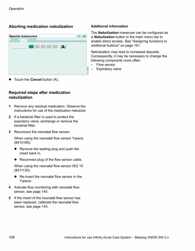
Operation
108 Instructions for use Infinity Acute Care System – Babylog VN500 SW 2.n
Aborting medication nebulization
Touch the Cancel button (A).
Required steps after medication nebulization
1 Remove any residual medication. Observe the instructions for use of the medication nebulizer.
2 If a bacterial filter is used to protect the expiratory valve, exchange or remove the bacterial filter.
3 Reconnect the neonatal flow sensor.
When using the neonatal flow sensor Y-piece (8410185):
Remove the sealing plug and push the insert back in.
Reconnect plug of the flow sensor cable.
When using the neonatal flow sensor ISO 15 (8411130):
Re-insert the neonatal flow sensor in the Y-piece.
4 Activate flow monitoring with neonatal flow sensor, see page 145.
5 If the insert of the neonatal flow sensor has been replaced, calibrate the neonatal flow sensor, see page 143.
Additional information
The Nebulization maneuver can be configured as a Nebulization button in the main menu bar to enable direct access. See "Assigning functions to additional buttons" on page 161.
Nebulization may lead to increased deposits. Consequently, it may be necessary to change the following compnents more often:– Flow sensor– Expiratory valve
34
3_
VN
50
0
Special maneuvers
A

Instructions for use Infinity Acute Care System – Babylog VN500 SW 2.n 109
Operation
Fitting the Aeroneb nebulizer
Observe the instructions for use of the Aeroneb nebulizer.
Observe the "Safety information for the use of HMEs, bacterial filters, and breathing circuits" on page 52.
Observe the "Safety information on medication nebulization" on page 103.
Do not switch on the Nebulization maneuver on Babylog VN500 as the Aeroneb nebulizer does not require a nebulizer flow from Babylog VN500.
Before nebulization with Aeroneb
1 Deactivate flow monitoring with neonatal flow sensor, see page 145.
2 Remove the neonatal flow sensor from the breathing circuit, see page 106.
After nebulization with Aeroneb
1 If a bacterial filter is used to protect the expiratory valve, exchange or remove the bacterial filter.
2 Reconnect the neonatal flow sensor.
When using the neonatal flow sensor Y-piece (8410185):
Remove the sealing plug and push the insert back in.
Reconnect plug of the flow sensor cable.
When using the neonatal flow sensor ISO 15 (8411130):
Re-insert the neonatal flow sensor in the Y-piece.
3 Activate flow monitoring with neonatal flow sensor, see page 145.
4 Calibrate the neonatal flow sensor, see page 143.
Additional information
For the order number of the Aeroneb nebulizer, see the list of accessories.
WARNING
Risk of fire
The measuring wires of the neonatal flow sensor are very hot and may ignite deposits of medication aerosols during nebulization.– Before medication nebulization, remove
the complete ISO 15 neonatal flow sensor, or remove the sensor insert from the neonatal flow sensor Y-piece and insert a sealing plug.
– Use additional monitoring since otherwise the minute volume is not monitored and apnea monitoring is limited.

Operation
110 Instructions for use Infinity Acute Care System – Babylog VN500 SW 2.n
GS500 gas supply unit
In order to ensure continuous Air supply, Babylog VN500 can be equipped with the GS500 gas supply unit. If Babylog VN500 is connected to the central gas supply system, GS500 ensures the supply of Air to the device in the case of failure of the central gas supply system and during intrahospital patient transport.
When Babylog VN500 is in the PC-HFO ventilation mode and is supplied from the gas supply unit GS500, it must be connected to an O2 compressed gas cylinder. The ejector is then operated using O2 instead of Air. This leads to a significantly increased O2 consumption which must be observed particularly during the transportation of patients within the hospital.
Installing the bacterial filter
Fit the bacterial filter (A) onto the inspiratory port.
Using the gas supply unit
Prerequisite: Functionality of the gas supply unit is activated, see "Configuring supply units" on page 186.
If Babylog VN500 is not connected to the central gas supply system, GS500 starts the supply of Air automatically.
In the event of failure of the central Air supply, or if the probe of the Air compressed gas hose becomes detached from the wall terminal unit of the central gas supply system, Babylog VN500 displays an alarm message. The gas supply unit starts the supply of Air using GS500 after 4 seconds at the latest.
Switching on the gas supply unit for intrahospital patient transport
1 Touch the Special maneuvers... button in the main menu bar.
2 Touch the Transport tab (A).
3 Touch the On button (B).
4 Pull out the probe of the Air compressed gas hose from the wall terminal unit of the central gas supply system.
34
2_
VN
50
0
A
32
5_
VN
50
0
Special maneuvers
ACB
Instructions for use Infinity Acute Care System – Babylog VN500 SW 2.n 111
Operation
If the probe of the Air compressed gas hose has not been pulled out within 5 minutes of the gas supply unit being switched on, Babylog VN500 switches off the gas supply unit.
5 Pull the probe of the O2 compressed gas hose out from the wall terminal unit of the central gas supply system and provide a replacement O2 supply if necessary.
Switching off the gas supply unit
Touch the Off button (C).
Additional information
Deactivating functionality of the gas supply unit, see "Configuring supply units" on page 186.
O2 therapy
Safety information for O2 therapy
During O2 therapy, only the O2 concentration and the inspiratory pressure are monitored.
Oxygen masks, hoods, or nasal cannulas can be used for O2 therapy.
Preparing O2 therapy
Attaching breathing hoses
CAUTION
Only use oxygen masks for the O2 therapy. Do not use masks for non-invasive ventilation (NIV). Use of unsuitable masks may jeopardize the patient.
CAUTION
Internal monitoring is deactivated. Airway pressure and ventilation parameters, e.g., flow, minute volume or apnea are not monitored. Use external SpO2 monitoring for patients who are dependent on an increased defined O2 concentration. Otherwise a worsening of the patient's condition cannot be detected.
NOTE
If the pressure needed for the set flow exceeds 30 mbar (30 cmH2O), the device issues an alarm and the safety valve is opened. The cause may be a kinked breathing hose or a blocked mask or nasal cannula.
Observe the specified flows and sizes of the particular accessories.
WARNING
Do not use antistatic or conductive breathing hoses. The use of these materials increases the risk of electric shock to the patient and of fire in an oxygen-enriched environment.
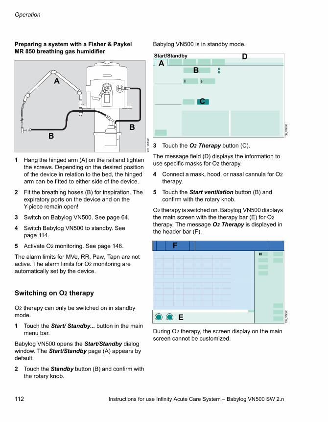
Operation
112 Instructions for use Infinity Acute Care System – Babylog VN500 SW 2.n
Preparing a system with a Fisher & Paykel MR 850 breathing gas humidifier
1 Hang the hinged arm (A) on the rail and tighten the screws. Depending on the desired position of the device in relation to the bed, the hinged arm can be fitted to either side of the device.
2 Fit the breathing hoses (B) for inspiration. The expiratory ports on the device and on the Y-piece remain open!
3 Switch on Babylog VN500. See page 64.
4 Switch Babylog VN500 to standby. See page 114.
5 Activate O2 monitoring. See page 146.
The alarm limits for MVe, RR, Paw, Tapn are not active. The alarm limits for O2 monitoring are automatically set by the device.
Switching on O2 therapy
O2 therapy can only be switched on in standby mode.
1 Touch the Start/ Standby... button in the main menu bar.
Babylog VN500 opens the Start/Standby dialog window. The Start/Standby page (A) appears by default.
2 Touch the Standby button (B) and confirm with the rotary knob.
Babylog VN500 is in standby mode.
3 Touch the O2 Therapy button (C).
The message field (D) displays the information to use specific masks for O2 therapy.
4 Connect a mask, hood, or nasal cannula for O2 therapy.
5 Touch the Start ventilation button (B) and confirm with the rotary knob.
O2 therapy is switched on. Babylog VN500 displays the main screen with the therapy bar (E) for O2 therapy. The message O2 Therapy is displayed in the header bar (F).
During O2 therapy, the screen display on the main screen cannot be customized.
03
7_
VN
50
0
A
BB
10
8_
VN
50
01
09
_V
N5
00
ADStart/Standby
C
B
1 2 3
F
E
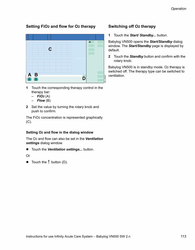
Instructions for use Infinity Acute Care System – Babylog VN500 SW 2.n 113
Operation
Setting FiO2 and flow for O2 therapy
1 Touch the corresponding therapy control in the therapy bar:– FiO2 (A)– Flow (B)
2 Set the value by turning the rotary knob and push to confirm.
The FiO2 concentration is represented graphically (C).
Setting O2 and flow in the dialog window
The O2 and flow can also be set in the Ventilation settings dialog window.
Touch the Ventilation settings... button.
Or
Touch the button (D).
Switching off O2 therapy
1 Touch the Start/ Standby... button.
Babylog VN500 opens the Start/Standby dialog window. The Start/Standby page is displayed by default.
2 Touch the Standby button and confirm with the rotary knob.
Babylog VN500 is in standby mode. O2 therapy is switched off. The therapy type can be switched to ventilation.
10
9_
VN
50
0
1 2 3
A B
C
D

Operation
114 Instructions for use Infinity Acute Care System – Babylog VN500 SW 2.n
Standby mode
Switch to standby mode for the following actions:– Keep Babylog VN500 ready for operation while
the patient is absent– Change the therapy type between ventilation
and O2 therapy– Change the patient category– Change the application mode– Perform the device and breathing circuit check– Query the status of accessories– Switch off Babylog VN500
Activating standby mode
1 Touch the Start/ Standby... button in the main menu bar.
Babylog VN500 opens the Start/Standby dialog window. The Start/Standby page (A) appears by default.
2 Touch the Standby button (B) and confirm with the rotary knob.
The message Standby mode activated is displayed in the header bar.
3 Touch the ALARM RESET button in the header bar and confirm with the rotary knob.
Babylog VN500 is in standby mode. Standby is displayed in the screen header bar.
WARNING
Ventilation does not take place in standby mode! The device must only be set to standby mode when no patient is connected to the device. The patient may otherwise be jeopardized.
36
7_
VN
50
0
Start/Standby
AB

Instructions for use Infinity Acute Care System – Babylog VN500 SW 2.n 115
Operation
Continuing the therapy
1 Check the ventilation settings (A) of the current patient.
Change the ventilation settings if necessary. Touch the Ventilation settings button (B). Babylog VN500 opens the corresponding page.
2 Touch the Start ventilation button (C) and confirm with the rotary knob.
The main screen is displayed; Babylog VN500 continues ventilating.
Additional information
If the patient category or the body weight is changed, Babylog VN500 determines new start-up values for ventilation. See "Admitting a new patient" on page 65.
For information on changing ventilation settings, see "Setting ventilation" on page 84.
36
7_
VN
50
0
Start/Standby
AB
A
C

Operation
116 Instructions for use Infinity Acute Care System – Babylog VN500 SW 2.n
Ending operation
1 Switch Babylog VN500 to standby mode: Touch the Start/ Standby... button in the main menu bar. Touch the Standby button and confirm with the rotary knob.
2 Press the key (A) on Infinity C500.
Babylog VN500 opens the Shut down device dialog.
3 Touch the OK button (B) and confirm with the rotary knob.
Babylog VN500 ends operation.
To return to standby mode:
Touch the Cancel button (C).
When Babylog VN500 is not in standby mode and the button (A) is pressed, the Start/Standby page is opened.
As soon as the screen is completely dark
Disconnect the mains plug from the mains power socket.
Pull the probe of the Air compressed gas hose and the probe of the O2 compressed gas hose out from the wall terminal units of the central gas supply system.
If Babylog VN500 cannot be switched off on account of a device malfunction
1 Open the device flap on the left side of Babylog VN500.
2 Set the toggle switch to (off).
Once the toggle switch has been pressed and the mains plug is disconnected, Babylog VN500 cannot be switched on.
Placing back into operation
1 Insert the mains plug into the mains power socket.
2 Open the device flap on the left side of Babylog VN500.
3 Set the toggle switch to (on).
4 Switch on Babylog VN500: Press the key on Infinity C500.
36
111
4
A
B C
Shut down device
CAUTION
Disconnect the compressed gas hoses from the central gas supply system. Otherwise minute internal leaks could contaminate the central gas supply system through the reverse flow of supply gases.

Instructions for use Infinity Acute Care System – Babylog VN500 SW 2.n 117
Operation
Disconnecting the device from the mains voltage
In the event of device malfunctions or other hazards, the device must be completely disconnected from the mains voltage.
When the toggle switch is at (off), only parts of the device are disconnected from the mains voltage. The batteries continue to be charged. To completely disconnect the device from the mains voltage, unplug the mains plug.
Storing Babylog VN500
Switch Babylog VN500 to energy-saving mode if storing for longer periods.
1 End operation. See "Ending operation" on page 116.
2 Set the toggle switch on the left side of Babylog VN500 to (off) immediately after switching off the device.
3 Disconnect the mains plug from the mains power socket.

Operation
118 Instructions for use Infinity Acute Care System – Babylog VN500 SW 2.n
Mains power supply / DC power supply
Components and terms
Mains power supply
The device is supplied with mains power via the power cable. Information on voltage ranges and mains power characteristic values can be found in chapter Technical Data, Operating data.
Internal battery
The internal battery is supplied with the device.
PS500 power supply unit
In addition to the internal battery, the device can optionally be equipped with the PS500 power supply unit.
Use of power supplies
The device is supplied with electric power from the following sources in the order stated:– Mains power– Batteries in the PS500 (if present)– Internal battery
The switch-over between these sources takes place without interruption to operation according to the following rules:– If the mains voltage is sufficient, the power is
supplied from the mains.– If the mains voltage is not sufficient or during a
battery check, the power is supplied from the batteries.
Display of power supplies
The power supply is displayed on the Infinity C500 operating and display unit.
On Infinity C500 (MS18746):
On Infinity C500 (MK31500):
A LED for mains power:– Lights green when mains power is applied
and the toggle switch is in the position.– If the LED does not light up, the device is
disconnected from the mains power.
B LED for the internal battery:– Lights green when the battery charge is
greater than approx. 90 %.– Lights yellow when the battery charge is
between approx. 10 % and 90 %.– Does not light if the internal battery is faulty,
discharged or device is switched off with the toggle switch (energy-saving mode).
01
73
58
A B
A B

Instructions for use Infinity Acute Care System – Babylog VN500 SW 2.n 119
Operation
Battery operation
Alarm messages during battery operation
Switch-over to the batteries is indicated with the alarm message Battery activated. The alarm priority can be configured, see "Setting the priority of the battery alarms" on page 167.
Alarm messages are displayed corresponding to the remaining battery capacity in order to warn against the complete discharge of the battery. Alarm messages, see chapter "Alarm – Cause – Remedy."
Reestablish the mains power supply immediately to avoid interruption of the ventilation functions.
When battery supply is no longer needed, recharge the batteries, see chapter "Battery charging".
Operating time during battery operation
The operating time depends on the following battery factors:– Age– Utilization (frequency, duration, and power
consumption)– Battery charge– Ambient temperature
For operating times when batteries are fully charged and new, and ventilation is typical, see chapters "Battery ageing" on page 324 and "Batteries" on page 276.
Observe the maintenance intervals.
Battery charging
The batteries are charged when the device is supplied with mains voltage. The symbol (A) is displayed in the screen header bar.
The batteries are charged in the following order:– Internal battery– Batteries in the PS500 (if present)
Charging times
For information on the charging times, see page 277.
Battery charge indication on the screen
The battery charge is indicated by the symbol (B) in the header bar on the screen. The battery charge indication applies to both charging and discharging. When the batteries are being charged, the last segment in the battery symbol flashes white.
The battery charge indication applies to both charging and discharging.
The battery charge indication always shows the total battery charge that is available. If there is a PS500 present, the battery charge available from the internal battery and the PS500 will be displayed.
NOTE
The LED indicates only the battery charge of the internal battery, even when the PS500 is present.
37
3
Symbol Battery charge
90 to 100 %
60 to <90 %
40 to <60 %
20 to <40 %
<20 %, flashes light and dark red in 1-second pulses
Batteries faulty or no information available on the battery charge
A B C

Operation
120 Instructions for use Infinity Acute Care System – Babylog VN500 SW 2.n
A flashing symbol (C) indicates the following:– The battery check is running.– The interval for the battery check has expired.– The last battery check failed.– Battery replacement is recommended.
Parameter field Battery
In addition to the battery charge indication, the Battery parameter field can be configured.
The Battery parameter field contains the following information:– PS500 (if present)
– Operating time in minutes (value corresponds to the operating time when the battery is used at the present power consumption) (A)
– Battery charge in percent (B)– Internal (internal battery)
– Operating time in minutes (value corresponds to the operating time when the battery is used at the present power consumption) (C)
– Battery charge in percent (D)
Care and maintenance of the batteries
Take note of the following points to limit premature ageing of the battery:– Operate the device under the stated ambient
conditions– Avoid storing the device with discharged or
partially discharged batteries– Connect the device to the mains power supply
after battery operation– Avoid shocks and vibrations– Perform the recommended battery checks
37
5
NOTE
Ageing and use of the batteries can result in a shorter operating time compared with new batteries.
Depending on the battery used, the battery charge is indicated to the nearest 5 or 10 minutes.
It is always the minimum calculated operating time that is displayed.
Battery
PS500
Internal
A
B
C
D
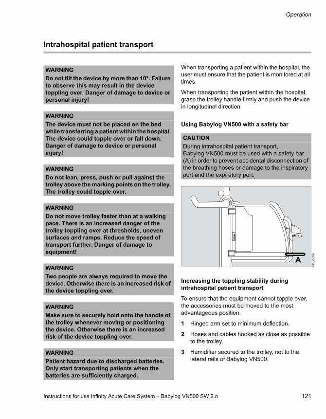
Instructions for use Infinity Acute Care System – Babylog VN500 SW 2.n 121
Operation
Intrahospital patient transport
When transporting a patient within the hospital, the user must ensure that the patient is monitored at all times.
When transporting the patient within the hospital, grasp the trolley handle firmly and push the device in longitudinal direction.
Using Babylog VN500 with a safety bar
Increasing the toppling stability during intrahospital patient transport
To ensure that the equipment cannot topple over, the accessories must be moved to the most advantageous position:
1 Hinged arm set to minimum deflection.
2 Hoses and cables hooked as close as possible to the trolley.
3 Humidifier secured to the trolley, not to the lateral rails of Babylog VN500.
WARNING
Do not tilt the device by more than 10°. Failure to observe this may result in the device toppling over. Danger of damage to device or personal injury!
WARNING
The device must not be placed on the bed while transferring a patient within the hospital. The device could topple over or fall down. Danger of damage to device or personal injury!
WARNING
Do not lean, press, push or pull against the trolley above the marking points on the trolley. The trolley could topple over.
WARNING
Do not move trolley faster than at a walking pace. There is an increased danger of the trolley toppling over at thresholds, uneven surfaces and ramps. Reduce the speed of transport further. Danger of damage to equipment!
WARNING
Two people are always required to move the device. Otherwise there is an increased risk of the device toppling over.
WARNING
Make sure to securely hold onto the handle of the trolley whenever moving or positioning the device. Otherwise there is an increased risk of the device toppling over.
WARNING
Patient hazard due to discharged batteries.Only start transporting patients when the batteries are sufficiently charged.
CAUTION
During intrahospital patient transport, Babylog VN500 must be used with a safety bar (A) in order to prevent accidental disconnection of the breathing hoses or damage to the inspiratory port and the expiratory port.
02
0_
VN
50
0
A

Operation
122 Instructions for use Infinity Acute Care System – Babylog VN500 SW 2.n
Additional information
Air supply from the GS500 gas supply unit, see "GS500 gas supply unit" on page 110.
Power supply, see "Mains power supply / DC power supply" on page 118.
For the order number of the safety bar, see the list of accessories.

Instructions for use Infinity Acute Care System – Babylog VN500 SW 2.n 123
Alarms
Alarms
Overview . . . . . . . . . . . . . . . . . . . . . . . . . . . . . 124
Display of alarms . . . . . . . . . . . . . . . . . . . . . . 124
Alarm priorities . . . . . . . . . . . . . . . . . . . . . . . . . 125Optical alarm signals . . . . . . . . . . . . . . . . . . . . 125Acoustic alarm signals . . . . . . . . . . . . . . . . . . . 125
Displaying information on alarms. . . . . . . . . 126
Displaying current alarms. . . . . . . . . . . . . . . . . 126Displaying the cause and remedy for an alarm. . . . . . . . . . . . . . . . . . . . . . . . . . . . . . . . . 126Acknowledging an alarm message that is no longer active . . . . . . . . . . . . . . . . . . . . . . . . . . . 126Acknowledging all alarm messages that are no longer active . . . . . . . . . . . . . . . . . . . . . . . . 126
Alarm history . . . . . . . . . . . . . . . . . . . . . . . . . 127
Setting alarm limits . . . . . . . . . . . . . . . . . . . . 128
How to set an alarm limit . . . . . . . . . . . . . . . . . 128Deactivating alarm limits. . . . . . . . . . . . . . . . . . 128Response to power failure . . . . . . . . . . . . . . . . 129Display of alarm limits in the parameter field . . 129
Setting the volume of the alarm tone . . . . . . 130
Suppressing the alarm tone . . . . . . . . . . . . . 131
Position of the user to the alarm system . . . 131
Failure of the acoustic alarm. . . . . . . . . . . . . 132

Alarms
124 Instructions for use Infinity Acute Care System – Babylog VN500 SW 2.n
Overview
Alarms are issued acoustically and visually. The alarm tone can be suppressed for 2 minutes.
The Alarms dialog window provides the following functions for selection:– Setting alarm limits– Displaying current alarms– Alarm history– Alarm settings
Display of alarms
In the event of an alarm, the system displays the relevant alarm message in the alarm message field (A). If the parameter field (B) is configured to display an individual parameter, the parameter field (B) of the parameter triggering the alarm flashes.The alarm bar (D) flashes in the color of the corresponding alarm priority.
If the alarm message field (A) contains more alarms than can be displayed, the More... button (C) appears in the header bar. Touching this button opens the page containing all the active alarms.
37
6_
VN
50
0
1 2 3
A
B
C
D
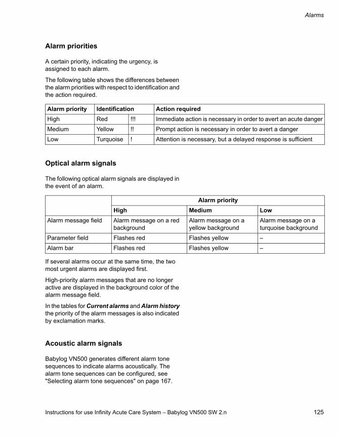
Instructions for use Infinity Acute Care System – Babylog VN500 SW 2.n 125
Alarms
Alarm priorities
A certain priority, indicating the urgency, is assigned to each alarm.
The following table shows the differences between the alarm priorities with respect to identification and the action required.
Optical alarm signals
The following optical alarm signals are displayed in the event of an alarm.
If several alarms occur at the same time, the two most urgent alarms are displayed first.
High-priority alarm messages that are no longer active are displayed in the background color of the alarm message field.
In the tables for Current alarms and Alarm history the priority of the alarm messages is also indicated by exclamation marks.
Acoustic alarm signals
Babylog VN500 generates different alarm tone sequences to indicate alarms acoustically. The alarm tone sequences can be configured, see "Selecting alarm tone sequences" on page 167.
Alarm priority Identification Action required
High Red !!! Immediate action is necessary in order to avert an acute danger
Medium Yellow !! Prompt action is necessary in order to avert a danger
Low Turquoise ! Attention is necessary, but a delayed response is sufficient
Alarm priority
High Medium Low
Alarm message field Alarm message on a red background
Alarm message on a yellow background
Alarm message on a turquoise background
Parameter field Flashes red Flashes yellow –
Alarm bar Flashes red Flashes yellow –

Alarms
126 Instructions for use Infinity Acute Care System – Babylog VN500 SW 2.n
Displaying information on alarms
Displaying current alarms
To display the current alarms, proceed as follows:
1 Touch the alarm message in the header bar.
Or
1 Touch the Alarms... button in the main menu bar.
2 Touch the Current alarms tab (A).
All the current alarm messages are displayed chronologically with the corresponding duration, priority and alarm message text in the list (B).
Displaying the cause and remedy for an alarm
1 Touch the alarm message or select it in the list (B) with the rotary knob.
2 Touch the button(C).
This displays the cause and remedy for the alarm message selected.
3 Eliminate the fault.
Additional information
For a list of causes and remedies, see chapter "Alarm – Cause – Remedy" on page 189.
Acknowledging an alarm message that is no longer active
After the fault has been eliminated, the alarm tone is silenced. Medium- and low-priority alarm messages expire automatically. High-priority alarm messages continue to be displayed for information after the cause of the alarm has been eliminated and need to be acknowledged.
1 Touch the ALARM RESET button (A) in the header bar.
2 Confirm with the rotary knob.
Acknowledging all alarm messages that are no longer active
Prerequisite: The Current alarms page (A) is opened.
1 Touch the Reset all button (B).
2 Confirm with the rotary knob.
The acknowledgeable messages are deleted in the header bar and in the list containing the current alarms. However, Babylog VN500 records all alarm messages in the alarm history.
08
2
A
B
Alarms C
07
8_
VN
50
00
82
1 2 3
A
AB
Alarms

Instructions for use Infinity Acute Care System – Babylog VN500 SW 2.n 127
Alarms
Alarm history
The alarm history records all alarm messages in chronological order.
The entries in the alarm history are also retained after the device has been switched off and on again or following a power supply failure.
The alarm history is part of the logbook. The length of the alarm history depends on the number of logbook entries.
When the logbook reaches its maximum size, the oldest entry in the logbook is deleted as each new entry is logged.
Switching the device off and on are not recorded in the logbook.
1 Touch the Alarms... button in the main menu bar.
2 Touch the Alarm history tab (A).
3 Use the buttons (B) to scroll in the alarm history.
09
4
AAlarms
B
B

Alarms
128 Instructions for use Infinity Acute Care System – Babylog VN500 SW 2.n
Setting alarm limits
Touch the Alarms... button in the main menu bar.
The Limits page (A) appears by default.
The alarm limit settings and the current measured value are displayed.
How to set an alarm limit
Prerequisite: The Limits page (A) is opened.
1 Touch the corresponding button for the alarm limit.
2 Set the value by turning the rotary knob and push to confirm.
Additional information
The start-up values for the alarm limits can be configured specifically as required by the hospital concerned, see page 165.
The alarm limits are displayed depending on the ventilation parameter in the parameter field.
Deactivating alarm limits
The following alarm limits can be deactivated:
How to deactivate an alarm limit
1 Touch the corresponding button for the alarm limit.
2 Continue turning the rotary knob until Off is displayed instead of the value.
3 Confirm with the rotary knob.
The alarm limit is deactivated. Babylog VN500 displays the symbol in the header bar and the deactivated alarm limit. The header bar can display up to 5 deactivated alarm limits.
09
6
(B) : Upper alarm limit
(C) Current value : Current measured value
(D) : Lower alarm limit
WARNING
The alarm limits must be set to meet the needs of the therapy required by the current patient. The patient may otherwise be jeopardized.Setting extreme alarm limits can render the alarm system useless.
BCD
Alarms
A
WARNING
Alarms must only be deactivated if the safety of the patient is not jeopardized by the absence of an alarm!
Patient category
Invasive ventilation
Non-invasive ventilation
Ped. pat. RR high MV low
– RR high
– Tapn
Neo. MV low –
RR high RR high
Tapn Tapn

Instructions for use Infinity Acute Care System – Babylog VN500 SW 2.n 129
Alarms
Response to power failure
Alarm limits are also retained in the event of a power failure, e.g., caused by a defective internal battery.
Display of alarm limits in the parameter field
If the alarm limits are assigned to a ventilation parameter, the alarm limits are displayed in the parameter fields for single parameters (standard and double size).
The following assignments have been defined:
Alarm limits Measured values
MV high, MV low MVe
Paw high PIP
RR high RR

Alarms
130 Instructions for use Infinity Acute Care System – Babylog VN500 SW 2.n
Setting the volume of the alarm tone
1 Touch the Alarms... button in the main menu bar.
2 Touch the Settings tab (A).
3 Touch the button (B).
4 Set the volume of the alarm tone by turning the rotary knob and push to confirm.
During the automatic switch-over between day and night modes, the alarm tone volume setting is overwritten by the volumes defined for these times. An automatic increase in volume can be activated. See "Setting the alarm tone" on page 167.
The lower value for the volume of the alarm tone is limited by the configured minimum volume of the alarm tone. The minimum volume can be configured on the System setup > Alarms > Alarm vol./tone page, see "Setting the alarm tone" on page 167.
Additional information
The Settings page can be configured for direct access into the main menu bar as the Alarm volume button. See "Assigning functions to additional buttons" on page 161.
WARNING
Unnoticed alarms in loud environments
Alarm situations are not recognized.
Set the volume of the alarm tone so that alarms can be heard.
09
5
Alarms
AB

Instructions for use Infinity Acute Care System – Babylog VN500 SW 2.n 131
Alarms
Suppressing the alarm tone
The alarm tone can be suppressed for a maximum of 2 minutes.
Press the (Audio paused) key (A).
This suppresses the acoustic alarm for 2 minutes.
Babylog VN500 displays the symbol in the header bar and the remaining time for the suppressed alarm tone.
If an alarm with a higher priority appears during this time, the alarm tone sounds once.
If the fault triggering the alarm is not eliminated after 2 minutes, the alarm tone sounds again.
Reactivate the alarm tone before the suppression time has elapsed:
Press the (Audio paused) key (A) again.
Position of the user to the alarm system
The optical alarm signals are designed as follows:
– At a distance of 4 m (157 in) it is possible to recognize which device is generating an alarm.
– At a distance of 1 m (39 in) the alarm message can be read clearly.
The alarm volume can be set so that the acoustic alarm signals can be heard in the vicinity of the device, see "Setting the alarm tone" on page 167.
36
2A

Alarms
132 Instructions for use Infinity Acute Care System – Babylog VN500 SW 2.n
Failure of the acoustic alarm
If the loudspeaker for acoustic alarm signaling (main alarm) fails on account of a defect, an intermittent tone will be generated by the loudspeaker for the auxiliary alarm.
This intermittent tone is also used for the power failure alarm.
Additional information on the power failure alarm
See "Failure of the power supply" on page 59.

Instructions for use Infinity Acute Care System – Babylog VN500 SW 2.n 133
Trends and data
Trends and data
Overview . . . . . . . . . . . . . . . . . . . . . . . . . . . . . 134
Displaying trends . . . . . . . . . . . . . . . . . . . . . . 134
Graphic trends . . . . . . . . . . . . . . . . . . . . . . . . . 134Apnea trend, apnea ventilation trend . . . . . . . . 136Tabular trend. . . . . . . . . . . . . . . . . . . . . . . . . . . 137
Displaying data . . . . . . . . . . . . . . . . . . . . . . . . 138
Displaying hospital-specific data . . . . . . . . . . . 138Displaying all measured values . . . . . . . . . . . . 138Displaying set values . . . . . . . . . . . . . . . . . . . . 138
Displaying the logbook . . . . . . . . . . . . . . . . . 139
Data export . . . . . . . . . . . . . . . . . . . . . . . . . . . 140

Trends and data
134 Instructions for use Infinity Acute Care System – Babylog VN500 SW 2.n
Overview
Babylog VN500 saves measured value and trend data. Trends are displayed in the form of a graphic or a table. The following can be displayed: current measured values, settings and hospital-specific combinations of measured and set values. The logbook can save up to a maximum of 5000 entries. Data can be exported with a USB storage medium.
The Trends/Data dialog window provides the following functions for selection:– Display trends– Display data– Logbook– Data export
Displaying trends
Trends are displayed as a graphic or a table. Trends are recorded for up to 7 days.
In graphic trends, measured values are displayed in blue and set values in green. In the apnea trend, the number of the apneic events that occurred per minute is represented as a histogram.In tabular trends, measured values are displayed in blue lettering and set values in green lettering.
Graphic trends
1 Touch the Trends/Data... button in the main menu bar.
Babylog VN500 opens the Trends page (A) with the Graphics 1 page (B).
Displaying an additional graphic trend
Prerequisite: The Trends page (A) is opened.
Touch the Graphics 2 tab (C).
Each page contains 2 graphic trend displays (D).
07
6
BA
Trends/Data
CE
D
D E

Instructions for use Infinity Acute Care System – Babylog VN500 SW 2.n 135
Trends and data
Selecting parameters for the graphic trend display
Prerequisite: The Graphics 1 or Graphics 2 page is open.
1 Touch the button (E).
The Setup dialog is displayed with the buttons for Meas. (F) and Settings (G).
The measurements (F) are divided into the following parameter types:– Pressures– Minute vol.– Volume/Flow– Gases– Timing/Cycl.– Others– Events
The settings (G) are divided into the following parameter types:– Pressures– Volume/Flow– Gases– Timing/Cycl.– Others
2 Touch the appropriate button for measurements or settings.
Another dialog containing all the parameters of the selected parameter type is displayed.
3 Touch the desired parameter.
4 Confirm with the OK button (H).
The dialog for the group selected is closed.
A maximum of 3 parameters can be selected for each graphic trend display. If 3 parameters are already selected, one parameter must be deselected before selecting a new parameter.
5 Select further parameters according to step 2 to 4.
6 Confirm the parameter selection with the OK button (H).
The selected parameters are displayed in the trend display. The Setup dialog is closed.
The selection can be canceled with Cancel (I). The previous selection is displayed in the graphic trend.
Clear (J) can be used to delete all parameter selections made.
Deselecting a parameter in the trend display
Touch the parameter to be deselected in the parameter type dialog. The button turns pale green.
13
8
SetupF G
HIJ

Trends and data
136 Instructions for use Infinity Acute Care System – Babylog VN500 SW 2.n
Selecting a time interval for the graphic trend display
Prerequisite: The Graphics 1 or Graphics 2 page is open.
1 Touch the button for the time interval (K).
2 Select the time interval from the selection list (2, 4, 8, 12 hours; 1 day, 7 days).
Displaying the value of a parameter at a certain moment in time
Position the cursor (L) on the time by turning the rotary knob or touching the time.
The parameter value and the marked time are displayed (M).
The marked time in the trend display also corresponds with the marked row of this time in the logbook.
Changing the displayed time period
Touch the buttons in the scrollbar (N) or turn the rotary knob.
Apnea trend, apnea ventilation trend
In the apnea trend, the number of the apneic events that occurred per minute is represented as a histogram. The number per minute is represented as a bar height. If an apnea lasts longer than one minute, the apnea is only counted once in the period of occurrence.
In the apnea ventilation trend, the system displays whether or not apnea ventilation is activated.
Prerequisite: The Graphics 1 or Graphics 2 page is open.
1 Touch the button.
2 In the Setup dialog window under Meas., touch the Events parameter type.
3 Select the Apnea or Apnea Vent. event.
A Apnea trend
B Apnea ventilation trend
Additional information
The apnea trend is only recorded when apnea ventilation is switched off.
The duration of an apnea is displayed only in the alarm history.
07
6
Trends/Data
K
LM
N
31
5
Trends/Data
A
B

Instructions for use Infinity Acute Care System – Babylog VN500 SW 2.n 137
Trends and data
Tabular trend
Babylog VN500 displays the trends of all parameters in a table. The parameters that are first displayed correspond with the parameters configured specifically for the hospital. These are followed by all measured values, and then all set values.
1 Touch the Trends/Data... button in the main menu bar.
2 Touch the Table tab (A).
The trend values for the parameters (B) with the units are displayed in 7 to 8 time columns (C). Use the buttons (F) to scroll in the trend table.
Selecting a time interval for the tabular trend display
1 Touch the button for the time interval (D).
2 Select the time interval from the selection list (5, 10, 30 minutes; 1, 2, 6, 12 hours; 1 day).
The tabular trends are available for the following times according to the selected time interval:
Displaying the value of a parameter at a certain moment in time
Position the cursor (E) on the time by turning the rotary knob or touching the time.
Additional information
"Configuring the display of hospital-specific measured values and settings" on page 160.
The Table page can be configured as the Trends table button in the main menu bar to enable direct access. See "Assigning functions to additional buttons" on page 161.
09
7
Time interval Availability
5, 10, 30 minutes 1 day
1 hour 2 days
2, 6, 12 hours, 1 day 7 days
A
ED
Trends/Data
B C F
F

Trends and data
138 Instructions for use Infinity Acute Care System – Babylog VN500 SW 2.n
Displaying data
The following data can be displayed:– Hospital-specific data– Measured values 1– Measured values 2– Set values
Measured values are displayed on a blue background and set values on a green background.
Displaying hospital-specific data
1 Touch the Trends/Data... button in the main menu bar.
2 Touch the Values tab (A).
Babylog VN500 opens the page containing the current, hospital-specific measured and set values (B).
Babylog VN500 displays the hospital-specific measured and set values (C) selected in the system setup.
Additional information
"Configuring the display of hospital-specific measured values and settings" on page 160.
Displaying all measured values
Prerequisite: The Values page (A) is opened.
Touch the Values 1 (B) or Values 2 (C) tab.
Displaying set values
Prerequisite: The Values page (A) is opened.
Touch the Settings tab (B).
Additional information
The Values page can be configured as the Values button in the main menu bar to enable direct access. See "Assigning functions to additional buttons" on page 161.
09
9
A
C
Trends/Data
C
B
13
91
40
A
CB
Trends/Data
B
Trends/Data
A

Instructions for use Infinity Acute Care System – Babylog VN500 SW 2.n 139
Trends and data
Displaying the logbook
The logbook records changes, events and alarms in chronological order. A maximum of 5000 logbook entries is possible. Events include, for example, use of the medication nebulizer or flow calibration. For alarms only the occurrence of the alarm condition is recorded, not its termination.
The entries in the logbook are also retained after the device has been switched off and on again or following a power supply failure.
1 Touch the Trends/Data... button in the main menu bar.
2 Touch the Logbook tab (A).
Babylog VN500 opens the logbook. The cursor (B) marks a row in the logbook. The marked row corresponds with the cursor position in the trend display.
For the marked row Babylog VN500 displays all the set values of the ventilation mode effective at this time in the field (C).
Displaying the setting parameters at another moment in time
Select the row by turning the rotary knob or touching the row.
With the button (D) the cursor will be moved backwards or forwards by at least 24 hours.
Additional information
The Logbook page can be configured as the Logbook button in the main menu bar to enable direct access. See "Assigning functions to additional buttons" on page 161.
09
0
Trends/Data
A
B
C
D
C

Trends and data
140 Instructions for use Infinity Acute Care System – Babylog VN500 SW 2.n
Data export
The data export takes place via a USB storage medium. A maximum of 5000 logbook entries from the last 7 days can be exported.
1 Insert the USB storage medium into a USB port on Infinity C500.
2 Touch the Trends/Data... button in the main menu bar.
3 Touch the Export data tab (A).
The following data can be exported:– Current settings and measured values (B)– Results obtained from the device check (C)– Results obtained from the breathing circuit
check (D)– Logbook 1 day or 7 days (E)– Alarm history 1 day or 7 days (F)– Trends 1 day or 7 days (G)
4 Touch the appropriate button for the export of the related data.
5 Touch the All data button (I) for the export of all the data.
The data is exported to the USB storage medium. After the successful completion of the data export, Babylog VN500 displays a message in the message field (H).
After the data export
Remove the USB storage medium from the USB port after waiting at least 2 seconds.
If data export was not successful
If data export fails owing to the USB storage medium being full, the buttons are deactivated.
Remove the USB storage medium from the USB port and use a different USB storage medium.
Additional information
The buttons are deactivated when a USB storage medium is not connected.
The exported files can only be viewed with a Unicode-enabled editor and a Unicode font.
An import into word processors or spreadsheets is possible.
12
7
Trends/Data
ABCDEFG
H
I

Instructions for use Infinity Acute Care System – Babylog VN500 SW 2.n 141
Monitoring
Monitoring
Information on monitoring. . . . . . . . . . . . . . . 142
Possible displays for measured values . . . . . . 142Information on the sensors used . . . . . . . . . . . 142
Flow monitoring . . . . . . . . . . . . . . . . . . . . . . . 143
Information on flow monitoring . . . . . . . . . . . . . 143Calibrating the neonatal flow sensor . . . . . . . . 143Deactivating or activating flow monitoring . . . . 145
O2 monitoring . . . . . . . . . . . . . . . . . . . . . . . . . 146
Calibrating the O2 sensor . . . . . . . . . . . . . . . . . 146Deactivating or activating O2 monitoring . . . . . 146
CO2 monitoring. . . . . . . . . . . . . . . . . . . . . . . . 147
Information on CO2 monitoring. . . . . . . . . . . . . 147Selecting the cuvette type . . . . . . . . . . . . . . . . 147Information on checking the CO2 sensor . . . . . 148Information on the alarm messages issued during CO2 monitoring . . . . . . . . . . . . . . . . . . . 148Checking the CO2 zero indication . . . . . . . . . . 149Performing a CO2 zero calibration . . . . . . . . . . 149Checking the calibration of the CO2 sensor with a test filter . . . . . . . . . . . . . . . . . . . . . . . . . 150Checking the calibration of the CO2 sensor with test gas . . . . . . . . . . . . . . . . . . . . . . . . . . . 151Performing the calibration of the CO2 sensor. . 152Deactivating or activating CO2 monitoring . . . . 153
Monitoring
142 Instructions for use Infinity Acute Care System – Babylog VN500 SW 2.n
Information on monitoring
Monitoring is activated at the factory. Each monitoring function can be deactivated separately.
O2 monitoring and flow monitoring are switched on after the device is switched on.
Possible displays for measured values
Instead of a measured value, the following displays are possible in the parameter fields or tables:
Display of etCO2 measurements
The measured value for etCO2 can be displayed in Vol%, kPa or mmHg. The display is configurable, see "Configuring units" on page 184.
Information on the sensors used
Babylog VN500 uses the following sensors for measurement and monitoring purposes:– Neonatal flow sensor– O2 sensor– Pressure sensor– CO2 sensor
Automatic calibration of the pressure sensors takes place immediately and an hour after the device has been switched on, afterwards every 12 hours.
For calibrating or checking the other sensors, see:– "Calibrating the neonatal flow sensor"
on page 143– "Calibrating the O2 sensor" on page 146– "Information on checking the CO2 sensor"
on page 148
The calibration or zero-checking values of the sensors that were last determined remain stored until the next calibration or zero check, even if the device is switched off.
Display Cause
Off Monitoring deactivated by user
ERR Sensor error
CAL Calibration active, no measured value display possible
Measured value?
Reduced sensor accuracy
No measured value
Prerequisites for measurement or calculation currently not met
+++ Measured value above specified measurement range
--- Measured value below specified measurement range
CAUTION
Regular calibration is essential to ensure that the sensors deliver reliable and accurate results. Otherwise the proper functioning of the device may be impaired.
Instructions for use Infinity Acute Care System – Babylog VN500 SW 2.n 143
Monitoring
Flow monitoring
Information on flow monitoring
The measured values for MVe and VTe are not leakage-corrected and are therefore lower than the actual minute and tidal volumes applied to the patient if a leakage occurs. When leakage compensation is activated, the measured volume and flow values as well as the curves for flow and volume are displayed with leakage correction.
Babylog VN500 compensates for leakages up to 100 % of the set tidal volume VT. Pressure-controlled ventilation is recommended in the case of larger leakages.
In order to avoid false alarms and assure proper monitoring, the following settings are required:
Adjust both alarm limits for MVe in line with the current value.
Use additional monitoring, e.g., external SpO2, if necessary.
Calibrating the neonatal flow sensor
Calibration of the neonatal flow sensor corresponds to a zero calibration.
Manual calibration of the neonatal flow sensor is necessary:– During the device check and before use– At least once a day– After replacing the neonatal flow sensor– After medication nebulization
Recalibration is not necessary if the neonatal flow sensor has been unplugged only briefly.
Before each manual calibration, whether started from the device check or from the Sensors/Parameters dialog window, Babylog VN500 automatically cleans the neonatal flow sensor by heating.
CAUTION
Patient hazard!
Use additional external monitoring during ventilation with very low tidal volumes.
WARNING
Risk of fire
Residual vapors of easily flammable disinfectants (e.g., alcohols) and deposits that were not removed during reprocessing can ignite when the flow sensor is in use.– Ensure particle-free cleaning and
disinfection.– After disinfection, allow the flow sensor to
air for at least 30 minutes.– Before inserting the flow sensor check for
visible damage and soiling, such as residual mucus, medication aerosols, and particles.
– Replace flow sensors when damaged, soiled, or not particle-free.

Monitoring
144 Instructions for use Infinity Acute Care System – Babylog VN500 SW 2.n
Starting calibration of the neonatal flow sensor
1 Touch the Sensors/ Parameters... button in the main menu bar.
Babylog VN500 opens the Sensors/Parameters dialog window. The Neonatal flow sensor page (A) appears by default.
Select the sensor type being used:
2 Touch the Y flow sensor (E) or ISO 15 flow sensor button (F).
3 Touch the Start button (B).
The instruction field (G) displays the instructions for performing calibration. Button (H) is preselected.
Removing the neonatal flow sensor
4 Remove the tube connector.
5 Put on a sterile glove.
6 Seal the neonatal flow sensor ISO 15 (I) or neonatal flow sensor Y-piece (J).
This ensures that the requirement for calibration (flow = 0) is met.
Performing calibration
7 Press the rotary knob.
Babylog VN500 calibrates the neonatal flow sensor.
Babylog VN500 displays calibration information in the message field (C).
Once calibration is complete, the Start button (B) turns pale green.
Canceling calibration of the neonatal flow sensor
Touch the Cancel button (D).
After calibration of the neonatal flow sensor
8 Connect the tube connector.
Setting the flow trigger
Touch the Trigger button (K).
Babylog VN500 opens the page for setting the flow trigger. For additional information, see "Additional settings for ventilation" on page 89.
Additional information
The Neonatal flow sensor page can be configured as the Neonatal flow sensor button in the main menu bar to enable direct access. See "Assigning functions to additional buttons" on page 161.
30
8_
VN
50
03
07
Sensors/Parameters
AB D
C
E
G
KF
H
I J

Instructions for use Infinity Acute Care System – Babylog VN500 SW 2.n 145
Monitoring
Deactivating or activating flow monitoring
The ventilation functions and ventilation monitoring are limited when flow monitoring is deactivated.
Flow monitoring can be deactivated, e.g.:– If medication nebulization is being performed– To permit ventilation in the event of major tube
leakage– If the flow sensor has failed but cannot be
replaced immediately.A defective or disconnected flow sensor can lead to deviations in the minute and tidal volumes or to auto-triggering.
In the Neo. patient category, Babylog VN500 deactivates flow monitoring when changing to the NIV application mode.
Deactivating flow monitoring with neonatal flow sensor
1 Touch the Sensors/ Parameters... button in the main menu bar.
2 Touch the Neonatal flow sensor tab (A).
3 Touch the Off button (B) and confirm with the rotary knob.
Babylog VN500 displays the following information in the message field (C): External monitoring must be used!
Flow monitoring with the neonatal flow sensor is deactivated. Babylog VN500 displays the symbol
Flow in the header bar. The measured values are no longer displayed. The alarm function is deactivated.
Activating flow monitoring with neonatal flow sensor
Reactivate flow monitoring after exchanging the neonatal flow sensor or as soon as possible.
Prerequisite: The Neonatal flow sensor page (A) is opened.
Touch the On button (D) and confirm with the rotary knob.
Flow monitoring is activated.
WARNING
If flow and volume monitoring is deactivated, ensure that appropriate substitute monitoring is available immediately. The patient may otherwise be jeopardized.
WARNING
No apnea monitoring takes place when flow monitoring is deactivated. Use an independent apnea monitoring.
CAUTION
Patient-triggered ventilation is not possible when flow monitoring with the neonatal flow sensor is deactivated.
30
8_
VN
50
0
Sensors/Parameters
A
BD
C

Monitoring
146 Instructions for use Infinity Acute Care System – Babylog VN500 SW 2.n
O2 monitoring
Calibrating the O2 sensor
The O2 sensor is calibrated during the device check. Regular calibration during the device check ensures the specified accuracy. If the O2 sensor is not calibrated for 3 months, the accuracy of the O2 sensor will be reduced. The parameter field for the O2 concentration displays a question mark in addition to the measured value.
After calibration during the device check the sensor will work again with full accuracy.
Additional information
"Performing the device check" on page 71.
The O2 sensor page can be configured as the O2 sensor button in the main menu bar to enable direct access. See "Assigning functions to additional buttons" on page 161.
The O2 sensor is deactivated in standby mode. When the therapy is started, the O2 concentration is not displayed until after about 5 seconds.
Deactivating or activating O2 monitoring
O2 monitoring can be replaced by appropriate substitute monitoring. Set the O2 alarm limits for the substitute monitoring according to the set value for FiO2:
Deactivating O2 monitoring
1 Touch the Sensors/ Parameters... button in the main menu bar.
2 Touch the O2 sensor tab (A).
3 Touch the Off button (B) and confirm with the rotary knob.
Babylog VN500 displays the following information in the message field (C): External monitoring must be used!
O2 monitoring is deactivated. Babylog VN500 displays the symbol FiO2 in the header bar. The measured values are no longer displayed. The corresponding alarm function is deactivated.
14
1
CAUTION
If the quality of the oxygen from the central gas supply system is inadequate, calibrate the O2 sensor with calibration gas (100 % O2). Otherwise this may result in an incorrect calibration.
FiO2 Vol%
22?
WARNING
If O2 monitoring is deactivated, ensure that appropriate substitute monitoring is available immediately. The patient may otherwise be jeopardized.
FiO2 <60 Vol% –> O2 ±4 Vol%
FiO2 60 Vol% –> O2 ±6 Vol%
111
_V
N5
00
A
B
Sensors/Parameters C
D

Instructions for use Infinity Acute Care System – Babylog VN500 SW 2.n 147
Monitoring
Activating O2 monitoring
Reactivate O2 monitoring as soon as possible.
Prerequisite: The O2 sensor page (A) is opened.
Touch the On button (D) and confirm with the rotary knob.
O2 monitoring is activated.
CO2 monitoring
Information on CO2 monitoring
The CO2 sensor page can be configured for direct access into the main menu bar as the CO2 sensor button. See "Assigning functions to additional buttons" on page 161.
Selecting the cuvette type
The following cuvettes can be used:– Reusable cuvettes– Disposable cuvettes
The cuvette type used must be selected on the Zero calib. on/off page.
1 Touch the Sensors/ Parameters... button in the main menu bar.
2 Touch the CO2 sensor tab (A).
The Zero calib. on/off page (B) appears by default.
3 Touch the Reusable (C) or Disposable button(D).
If the selected cuvette does not correspond to the cuvette used, the alarm message Check CO2 cuvette is displayed.
CAUTION
The cuvette windows of the reusable cuvette have different optical properties to the cuvette windows of the disposable cuvette. The cuvette type used must therefore be selected correctly on the Zero calib. on/off page. Otherwise the zero point will be shifted by up to 8 mmHg CO2.
14
2_
VN
50
0
Sensors/Parameters
AB
C D

Monitoring
148 Instructions for use Infinity Acute Care System – Babylog VN500 SW 2.n
Information on checking the CO2 sensor
The CO2 sensor is factory-calibrated and can be used on any Babylog VN500.
Information on checking the zero indication and zero calibration
When checking the zero indication or performing zero calibration, the CO2 concentration in the cuvette or in the cuvette slot of the sensor must not be higher than the background concentration in rooms of approximately 0.4 mmHg or 0.05 Vol%. For this reason, do not breathe on or into the cuvettes or into the cuvette slot.
The following checks are required for the CO2 sensor:
Zero calibration in ambient air, calibration check with test filter or test gas and calibration of the CO2 sensor can be performed during ventilation.
Information on the alarm messages issued during CO2 monitoring
This information refers to the alarm messages which are generated due to a soiled cuvette or sensor.
Alarm message Clean CO2 cuvette
If the Clean CO2 cuvette message is displayed, the following panes may be soiled:– Cuvette (disposable or reusable cuvette)– CO2 sensor
1 Clean the cuvette or use another cuvette.– When using reusable cuvettes, insert a
clean reusable cuvette.– When using disposable cuvettes, insert a
new disposable cuvette.
2 Clean the CO2 sensor.
Alarm message CO2 zero calibration?
If the CO2 zero calibration? message is displayed or if incorrect measured values are suspected, e.g., etCO2 values too low or inspiratory values too high, then proceed as follows:
1 Check whether the cuvette windows are soiled.
2 Clean the soiled windows. Or, if a reusable cuvette was used previously, use a clean reusable cuvette. If a disposable cuvette was used previously, use a new disposable cuvette.
If the cuvette windows are extremely soiled, e.g., from deposits due to medication nebulization, this may result in a zero shift. The CO2 measured values may be incorrect even before insufficient measuring light causes the Clean CO2 cuvette message to appear.
If the CO2 zero calibration? message does not disappear or if the measured CO2 values remain suspect, a zero calibration must be performed.
Check When required?
Check CO2 zero indication in ambient air
Required before measurement and when changing the CO2 sensor to another ventilation unit.
Perform a CO2 zero calibration
If the CO2 zero indication in ambient air is not between 0 and 1 mmHg (or 0 and 0.1 Vol%, or 0 and 0.1 kPa).
Check calibration of the CO2 sensor with a test filter
Required in intervals of one month.
Check calibration of the CO2 sensor with test gas
When the test values are not adhered to during the calibration check with test filter.
Perform calibration of the CO2 sensor
When the test values are not adhered to during the calibration check with test gas.

Instructions for use Infinity Acute Care System – Babylog VN500 SW 2.n 149
Monitoring
Checking the CO2 zero indication
The check of the CO2 zero indication in ambient air is performed with a clean CO2 sensor that is placed on the cuvette used for measurement.
Prerequisite: Babylog VN500 is switched on and at least the three-minute warm-up phase for the CO2 sensor has elapsed. After 3 minutes, the measured CO2 values will be inside the specified tolerance range.
1 Fit the CO2 sensor on the cuvette.
2 Select the cuvette type, see page 147.
3 To display CO2 measured values as a curve, see "Changing the display of monitoring fields" on page 95.
4 Remove the CO2 sensor with the cuvette from the breathing circuit and hold it in ambient air. Do not breathe on or into the cuvette.
Instead of the cuvette from the breathing circuit, another clean cuvette of the selected type (disposable or reusable) can be used.
5 Observe the measured CO2 value. If 0 to 1 mmHg (or 0 to 0.1 Vol% or 0 to 0.1 kPa) is not displayed in the ambient air, perform a zero calibration.
Performing a CO2 zero calibration
Zero calibration is performed in ambient air and with a clean CO2 sensor which is removed from the cuvette.
Prerequisite: Babylog VN500 is switched on and at least the three-minute warm-up phase for the CO2 sensor has elapsed. After 3 minutes, the measured CO2 values will be inside the specified tolerance range.
Starting zero calibration
1 Touch the Sensors/ Parameters... button in the main menu bar.
2 Touch the CO2 sensor tab (A).
The Zero calib. on/off page (B) appears by default.
3 Touch the Start button (C).
When requested by Babylog VN500:
4 Remove the CO2 sensor (D) from the cuvette (E).
5 Confirm with the rotary knob.
Babylog VN500 performs the zero calibration and displays the message Calibration in progress.
14
2_
VN
50
01
79
_V
N5
00
Sensors/Parameters
AB
C
D
E

Monitoring
150 Instructions for use Infinity Acute Care System – Babylog VN500 SW 2.n
If zero calibration was successful
After approximately 5 seconds, Babylog VN500 reports Zero calibration successful.
Fit the CO2 sensor (D) back on the cuvette (E).
If zero calibration was not successful
Babylog VN500 reports Zero calibration failed.
Repeat zero calibration.
If zero calibration is still impossible
1 Check whether the sensor is soiled and clean it if necessary. If the sensor is faulty, replace it.
2 Repeat zero calibration.
Checking the calibration of the CO2 sensor with a test filter
Perform the calibration check of the CO2 sensor with a test filter at intervals of one month.
Before the check
Prerequisite: Babylog VN500 is switched on and at least the three-minute warm-up phase for the CO2 sensor has elapsed.
Perform CO2 zero calibration in ambient air.
Starting the calibration check of the CO2 sensor with a test filter
Prerequisite: The CO2 sensor page (A) is opened.
1 Touch the Check sensor tab (B).
2 Remove the sensor from the cuvette and connect it to the test filter (E) on the sensor cable.
3 Touch the Filter check button (C) and confirm with the rotary knob.
Babylog VN500 starts the check and displays the progress and result of the check in the message field (D).
If the check was successful
Babylog VN500 displays the message Filter check successful.. The test value is within the permissible tolerance.
Fit the CO2 sensor back on the cuvette.
If the check was not successful
Babylog VN500 displays the message Filter check failed.. The test value is outside the permissible tolerance.
Check the CO2 calibration with test gas.
14
3
Sensors/Parameters
A
BC
D
17
7
E

Instructions for use Infinity Acute Care System – Babylog VN500 SW 2.n 151
Monitoring
Checking the calibration of the CO2 sensor with test gas
Perform the check when the test values are not within the permitted tolerance during the calibration check of the CO2 sensor with test filter.
Before the check
Prerequisite: Babylog VN500 is switched on and at least the three-minute warm-up phase for the CO2 sensor has elapsed.
Perform CO2 zero calibration in ambient air.
Connecting the test gas supply
The test gas must consist only of CO2 and N2!
1 Use the reusable cuvette from the calibration set!
At the start of the check with test gas, Babylog VN500 automatically sets the cuvette type to Reusable.
2 Connect the test gas cylinder (A) and the cuvette (B) of the calibration set to the hose (C).
3 Fit the CO2 sensor (D) on the cuvette (B) from the calibration set.
4 Read the CO2 concentration of the test gas from the test gas cylinder (A).
5 Open the test gas cylinder (E) and set the test gas flow to 0.1 L/min.
Starting the calibration check of the CO2 sensor with test gas
Prerequisite: The CO2 sensor page (F) is opened.
1 Touch the Check sensor tab (G).
2 Touch the Gas check button (H).
Babylog VN500 displays the measured CO2 concentration (I).
About 1 minute after the test gas flow has been set, the measured CO2 value must match the CO2 content of the test gas read from the test gas cylinder with a tolerance of ±0.2 Vol%.
Babylog VN500 terminates the check with test gas approx. 1 minute after the start.
3 Close the test gas cylinder again.
If the test value is outside the permitted tolerance, the CO2 sensor must be recalibrated with test gas.
CAUTION
For the check and calibration only use a test gas which consists of CO2 and N2! Otherwise display deviations of ±0.5 Vol% CO2 may occur.
17
6
A
B
C
D
E
14
3_
VN
50
0
Sensors/Parameters
F
G
H I
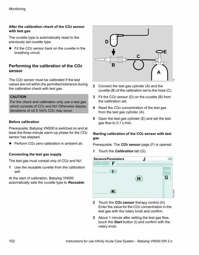
Monitoring
152 Instructions for use Infinity Acute Care System – Babylog VN500 SW 2.n
After the calibration check of the CO2 sensor with test gas
The cuvette type is automatically reset to the previously set cuvette type.
Fit the CO2 sensor back on the cuvette in the breathing circuit.
Performing the calibration of the CO2 sensor
The CO2 sensor must be calibrated if the test values are not within the permitted tolerance during the calibration check with test gas.
Before calibration
Prerequisite: Babylog VN500 is switched on and at least the three-minute warm-up phase for the CO2 sensor has elapsed.
Perform CO2 zero calibration in ambient air.
Connecting the test gas supply
The test gas must consist only of CO2 and N2!
1 Use the reusable cuvette from the calibration set!
At the start of calibration, Babylog VN500 automatically sets the cuvette type to Reusable.
2 Connect the test gas cylinder (A) and the cuvette (B) of the calibration set to the hose (C).
3 Fit the CO2 sensor (D) on the cuvette (B) from the calibration set.
4 Read the CO2 concentration of the test gas from the test gas cylinder (A).
5 Open the test gas cylinder (E) and set the test gas flow to 0.1 L/min.
Starting calibration of the CO2 sensor with test gas
Prerequisite: The CO2 sensor page (F) is opened.
1 Touch the Calibration tab (G).
2 Touch the CO2 sensor therapy control (H). Enter the value for the CO2 concentration in the test gas with the rotary knob and confirm.
3 About 1 minute after setting the test gas flow, touch the Start button (I) and confirm with the rotary knob.
CAUTION
For the check and calibration only use a test gas which consists of CO2 and N2! Otherwise display deviations of ±0.5 Vol% CO2 may occur.
17
61
44
_V
N5
00
A
B
C
D
E
Sensors/Parameters
F
GI
H
K
J
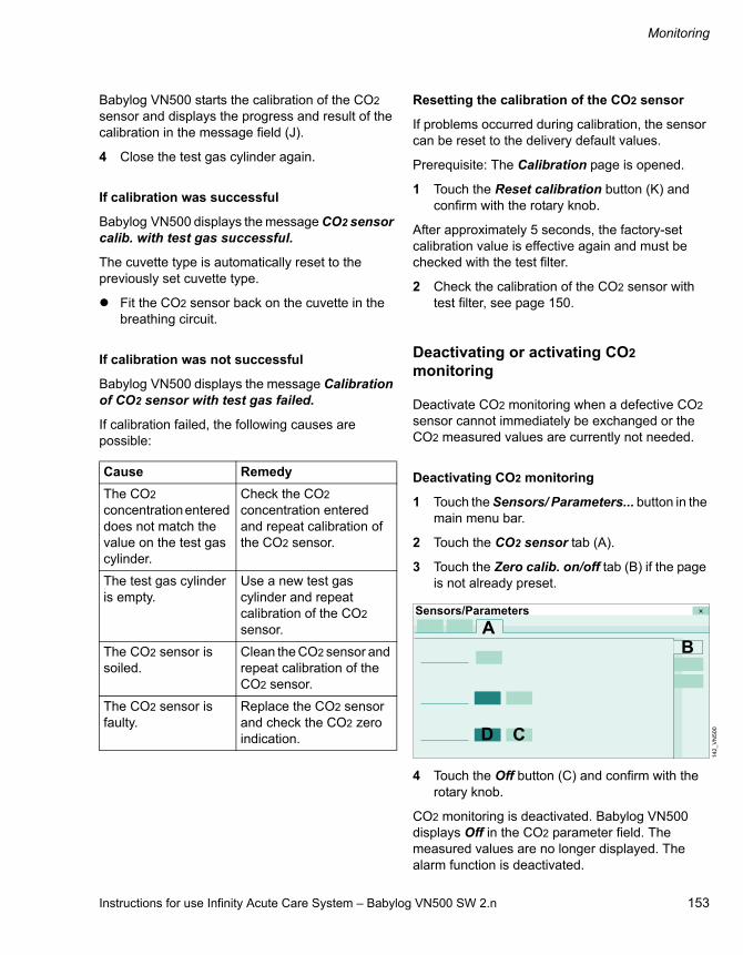
Instructions for use Infinity Acute Care System – Babylog VN500 SW 2.n 153
Monitoring
Babylog VN500 starts the calibration of the CO2 sensor and displays the progress and result of the calibration in the message field (J).
4 Close the test gas cylinder again.
If calibration was successful
Babylog VN500 displays the message CO2 sensor calib. with test gas successful.
The cuvette type is automatically reset to the previously set cuvette type.
Fit the CO2 sensor back on the cuvette in the breathing circuit.
If calibration was not successful
Babylog VN500 displays the message Calibration of CO2 sensor with test gas failed.
If calibration failed, the following causes are possible:
Resetting the calibration of the CO2 sensor
If problems occurred during calibration, the sensor can be reset to the delivery default values.
Prerequisite: The Calibration page is opened.
1 Touch the Reset calibration button (K) and confirm with the rotary knob.
After approximately 5 seconds, the factory-set calibration value is effective again and must be checked with the test filter.
2 Check the calibration of the CO2 sensor with test filter, see page 150.
Deactivating or activating CO2 monitoring
Deactivate CO2 monitoring when a defective CO2 sensor cannot immediately be exchanged or the CO2 measured values are currently not needed.
Deactivating CO2 monitoring
1 Touch the Sensors/ Parameters... button in the main menu bar.
2 Touch the CO2 sensor tab (A).
3 Touch the Zero calib. on/off tab (B) if the page is not already preset.
4 Touch the Off button (C) and confirm with the rotary knob.
CO2 monitoring is deactivated. Babylog VN500 displays Off in the CO2 parameter field. The measured values are no longer displayed. The alarm function is deactivated.
Cause Remedy
The CO2 concentration entered does not match the value on the test gas cylinder.
Check the CO2 concentration entered and repeat calibration of the CO2 sensor.
The test gas cylinder is empty.
Use a new test gas cylinder and repeat calibration of the CO2 sensor.
The CO2 sensor is soiled.
Clean the CO2 sensor and repeat calibration of the CO2 sensor.
The CO2 sensor is faulty.
Replace the CO2 sensor and check the CO2 zero indication.
14
2_
VN
50
0
Sensors/Parameters
AB
CD

Monitoring
154 Instructions for use Infinity Acute Care System – Babylog VN500 SW 2.n
Activating CO2 monitoring
Prerequisite: The Zero calib. on/off page (B) is opened.
Touch the On button (D) and confirm with the rotary knob.
CO2 monitoring is activated.
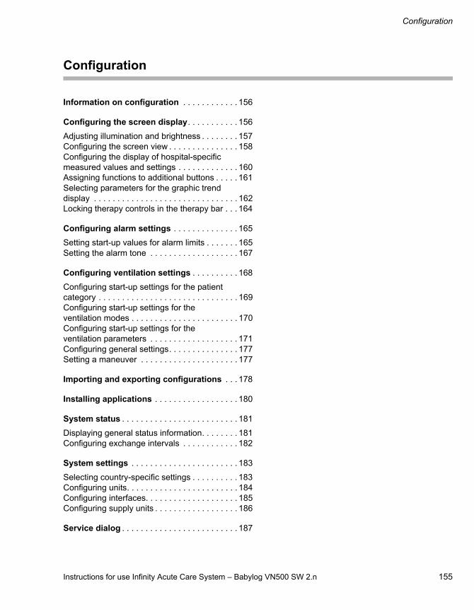
Instructions for use Infinity Acute Care System – Babylog VN500 SW 2.n 155
Configuration
Configuration
Information on configuration . . . . . . . . . . . . 156
Configuring the screen display. . . . . . . . . . . 156
Adjusting illumination and brightness . . . . . . . . 157Configuring the screen view . . . . . . . . . . . . . . . 158Configuring the display of hospital-specific measured values and settings . . . . . . . . . . . . . 160Assigning functions to additional buttons . . . . . 161Selecting parameters for the graphic trend display . . . . . . . . . . . . . . . . . . . . . . . . . . . . . . . 162Locking therapy controls in the therapy bar . . . 164
Configuring alarm settings . . . . . . . . . . . . . . 165
Setting start-up values for alarm limits . . . . . . . 165Setting the alarm tone . . . . . . . . . . . . . . . . . . . 167
Configuring ventilation settings . . . . . . . . . . 168
Configuring start-up settings for the patient category . . . . . . . . . . . . . . . . . . . . . . . . . . . . . . 169Configuring start-up settings for the ventilation modes . . . . . . . . . . . . . . . . . . . . . . . 170Configuring start-up settings for the ventilation parameters . . . . . . . . . . . . . . . . . . . 171Configuring general settings. . . . . . . . . . . . . . . 177Setting a maneuver . . . . . . . . . . . . . . . . . . . . . 177
Importing and exporting configurations . . . 178
Installing applications . . . . . . . . . . . . . . . . . . 180
System status . . . . . . . . . . . . . . . . . . . . . . . . . 181
Displaying general status information. . . . . . . . 181Configuring exchange intervals . . . . . . . . . . . . 182
System settings . . . . . . . . . . . . . . . . . . . . . . . 183
Selecting country-specific settings . . . . . . . . . . 183Configuring units. . . . . . . . . . . . . . . . . . . . . . . . 184Configuring interfaces. . . . . . . . . . . . . . . . . . . . 185Configuring supply units . . . . . . . . . . . . . . . . . . 186
Service dialog . . . . . . . . . . . . . . . . . . . . . . . . . 187
Configuration
156 Instructions for use Infinity Acute Care System – Babylog VN500 SW 2.n
Information on configuration
The System setup dialog window provides the user with the following configuration options:– Screen layout– Alarms– Ventilation– Config. exchange (Importing and exporting
configurations)– Applications– System status– Exchange intervals– System
To prevent unauthorized adjustments, the following pages are password-protected:– Screen layout > Views– Alarms– Ventilation– Config. exchange– Applications– Exchange intervals
The password only needs to be entered once as long as the System setup dialog window remains open.
For additional information on the password, see page 341.
Configuring the screen display
The following settings can be configured on the System setup > Screen layout page:– General settings (General settings)– Views– Customized data (Customized data)– Config. buttons (Configurable buttons)– Trends graphic 1– Trends graphic 2– Therapy bar
The customized settings for Trends graphic 1 and Trends graphic 2 become effective with the admission of a new patient. The other customized screen display settings are immediately effective.
Touch the System setup... button.
Babylog VN500 opens the System setup dialog window. The Screen layout page is displayed by default.

Instructions for use Infinity Acute Care System – Babylog VN500 SW 2.n 157
Configuration
Adjusting illumination and brightness
Prerequisite: The Screen layout page (A) is opened.
1 Touch the General settings tab (B).
Automatic changeover of day and night mode
If the automatic changeover of day and night mode is switched on, the system will automatically change over the following settings:– Illumination of the screen– Volume of the alarm tone– Automatic increase of the alarm tone volume
Touch button On (C) or Off (D).
Selecting the time period for screen illumination at night
The illumination of the screen is reduced with a dark background color for the time period entered.
Hours (E) : minutes (F) to hours (G) : minutes (H).
1 Touch the appropriate button.
2 Set the time by turning the rotary knob and push to confirm.
If the automatic changeover for the illumination of the screen is switched on, the system will change over at the times entered.
The Day/Night button in the main menu bar can be configured to enable direct access to the reduced screen illumination mode that uses a dark background color, see page 161.
Adjusting screen brightness
The screen brightness can be adjusted automatically or manually.
Activating automatic brightness adjustment:
Touch the Automatic button (I).
Adjusting brightness manually:
1 Touch the Manual button (J).
2 Touch the button (K).
3 Set the value by turning the rotary knob and push to confirm.
Adjusting automatic screen dimming
Automatic dimming of the screen can be set for standby mode and battery operation.
1 Touch the On button (L).
2 Touch the button (N).
3 Set the value by turning the rotary knob and push to confirm.
Switching off automatic screen dimming:
Touch the Off button (M).
13
2
: :B
System setup
A
F GE H
I
C D
M NLJ K

Configuration
158 Instructions for use Infinity Acute Care System – Babylog VN500 SW 2.n
Configuring the screen view
Prerequisite: The Screen layout page (A) is opened.
1 Touch the Views tab (B).
2 Enter password and confirm with Enter.
The Views page is displayed.
Selecting the view
3 Touch the button (C).
Babylog VN500 opens the selection list for the views. Three views can be configured (View 1 to View 3).
4 Select the respective view by turning the rotary knob and push to confirm.
Selecting the format template
The format templates can only be selected if the selected view is not locked. The button (G) is dark green.
5 Touch the button (D).
Babylog VN500 opens the selection list containing the existing format templates.
6 Select the desired template by turning the rotary knob and push to confirm.
The selected format template is displayed (E).
Adjusting the selected view
7 Touch a field in the view (E).
The dialog for the field contents is displayed.
8 Select the parameter, display format and display size for curves and parameter fields. See "Changing the display of monitoring fields" on page 95.
Locking the view against overwriting
Touch the button (F).
The selected view is locked and cannot be changed. The display of the monitoring fields cannot be changed on the main page.
Deactivating the lock
Touch the button (G).
Saving the view
1 Touch the button (H).
2 Confirm with the rotary knob.
The current view for the selected view (View 1 to View 3) is saved.
Reset current view
Each view can be reset individually, either to factory or saved settings. The view must not be locked.
Loading factory settings
1 Touch the Dräger default button (I).
2 Confirm with the rotary knob.
For information on the factory settings for the views, see chapter "Factory-set screen views" on page 335.
Loading saved settings
1 Touch the Load button (J).
2 Confirm with the rotary knob.
13
3
System setup
B
CD EG F
H
J
A
I

Instructions for use Infinity Acute Care System – Babylog VN500 SW 2.n 159
Configuration
Overview of format templates
The following format templates are available for selection:
The (K), (L) and (M) fields can be configured with customized settings. All fields can also be configured without contents. The following settings are possible:
08
9
K K
K K
K
L L L
LLL
L L LM
K L M
Field size 1x Field size 2x Field size 1x Field size 2x
Waveform
Trends (meas.)
Trends (settings)
Trends table
Multi Trend
Alarm history
Waveform
Loop
Double loop
Trends (meas.)
Trends (settings)
Trends table
Multi Trend
Alarm history
Lung display (Smart Pulmonary View)
Single parameter
Double parameter
Trends (meas.)
Trends (settings)
Single parameter
Parameter groups
Loop
Trends (meas.)
Trends (settings)
Single parameter
Double parameter
Parameter groups
Waveform
Loop
Double loop
Trends (meas.)
Trends (settings)
Trends table
Multi Trend
Alarm history
Lung display (Smart Pulmonary View)
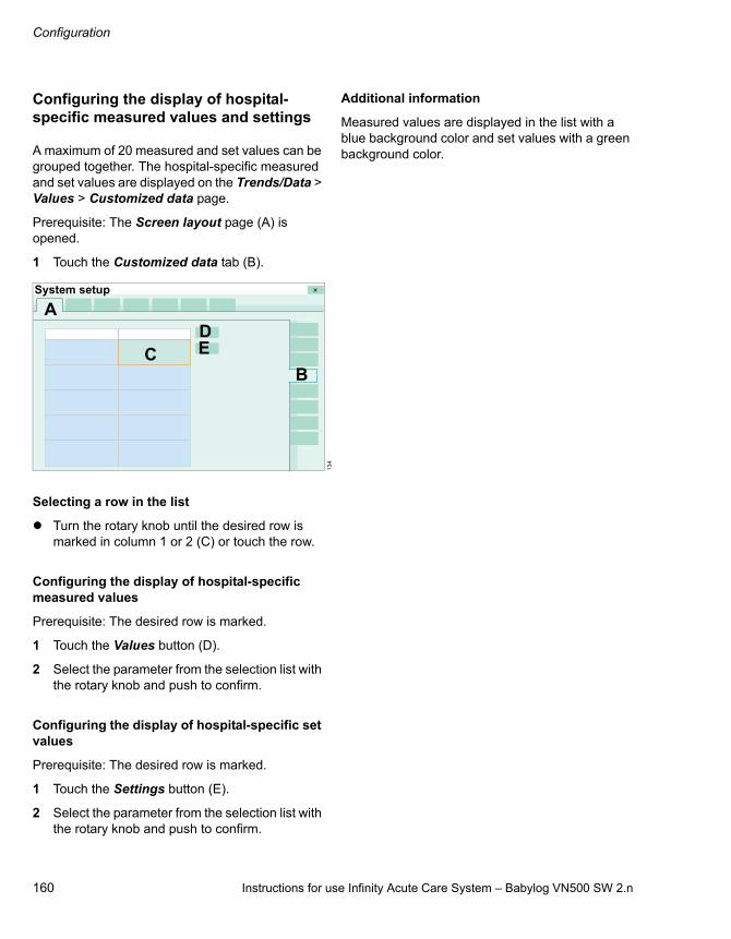
Configuration
160 Instructions for use Infinity Acute Care System – Babylog VN500 SW 2.n
Configuring the display of hospital-specific measured values and settings
A maximum of 20 measured and set values can be grouped together. The hospital-specific measured and set values are displayed on the Trends/Data > Values > Customized data page.
Prerequisite: The Screen layout page (A) is opened.
1 Touch the Customized data tab (B).
Selecting a row in the list
Turn the rotary knob until the desired row is marked in column 1 or 2 (C) or touch the row.
Configuring the display of hospital-specific measured values
Prerequisite: The desired row is marked.
1 Touch the Values button (D).
2 Select the parameter from the selection list with the rotary knob and push to confirm.
Configuring the display of hospital-specific set values
Prerequisite: The desired row is marked.
1 Touch the Settings button (E).
2 Select the parameter from the selection list with the rotary knob and push to confirm.
Additional information
Measured values are displayed in the list with a blue background color and set values with a green background color.
13
4
System setup
B
DC E
A

Instructions for use Infinity Acute Care System – Babylog VN500 SW 2.n 161
Configuration
Assigning functions to additional buttons
Additional buttons can be assigned in the main menu bar to enable direct access to a function or to directly open a page. The buttons are spatially assigned to the corresponding group.
Prerequisite: The Screen layout page (A) is opened.
1 Touch the Config. buttons tab (B).
In the first column (C), the buttons can be selected for the left column of the main menu bar. In the second column (D), the buttons can be selected for the right column of the main menu bar.
2 Touch the button.
3 Select the desired button from the selection list with the rotary knob and push to confirm.
Babylog VN500 displays the selected button in the main menu bar.
Additional information
For information on the display of additional buttons and their location in the main menu bar, see "Main menu bar structure" on page 331.
13
5
System setup
BC D
A

Configuration
162 Instructions for use Infinity Acute Care System – Babylog VN500 SW 2.n
Selecting parameters for the graphic trend display
The graphic trend display for the Trends/Data > Trends > Graphics 1 and Graphics 2 pages can be configured. The settings become effective with the admission of a new patient.
Prerequisite: The Screen layout page (A) is opened.
1 Touch the Trends graphic 1 (B) or Trends graphic 2 (C) tab.
Each page contains 2 graphic trend displays (D). A maximum of 3 parameters can be configured for each trend display.
Configuring the trend display
1 Touch the button (E).
Babylog VN500 opens the Setup dialog with the buttons for Meas. (F) and Settings (G).
The measured values (F) are divided into the following parameter types:– Pressures– Minute vol.– Volume/Flow– Gases– Timing/Cycl.– Others– Events
The settings (G) are divided into the following parameter types:– Pressures– Volume/Flow– Gases– Timing/Cycl.– Others
2 Touch the appropriate button for measured values or set values.
13
7
System setup
B
D
D
E
E
A
C
13
8
SetupF G
HIJ
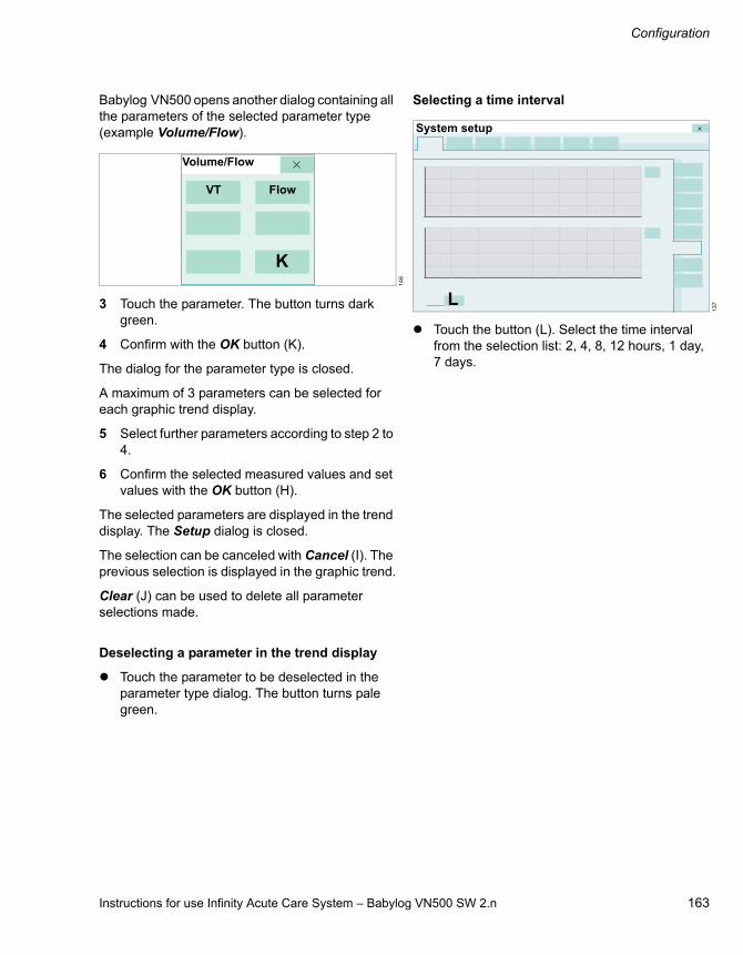
Instructions for use Infinity Acute Care System – Babylog VN500 SW 2.n 163
Configuration
Babylog VN500 opens another dialog containing all the parameters of the selected parameter type (example Volume/Flow).
3 Touch the parameter. The button turns dark green.
4 Confirm with the OK button (K).
The dialog for the parameter type is closed.
A maximum of 3 parameters can be selected for each graphic trend display.
5 Select further parameters according to step 2 to 4.
6 Confirm the selected measured values and set values with the OK button (H).
The selected parameters are displayed in the trend display. The Setup dialog is closed.
The selection can be canceled with Cancel (I). The previous selection is displayed in the graphic trend.
Clear (J) can be used to delete all parameter selections made.
Deselecting a parameter in the trend display
Touch the parameter to be deselected in the parameter type dialog. The button turns pale green.
Selecting a time interval
Touch the button (L). Select the time interval from the selection list: 2, 4, 8, 12 hours, 1 day, 7 days.
14
6
Volume/Flow
VT
K
Flow
13
7
System setup
L

Configuration
164 Instructions for use Infinity Acute Care System – Babylog VN500 SW 2.n
Locking therapy controls in the therapy bar
The therapy controls in the therapy bar can be locked to prevent accidental changes from being made to the ventilation parameters.
Prerequisite: The Screen layout page (A) is opened.
1 Touch the Therapy bar tab (B).
2 Touch the On button (C).
The therapy controls in the therapy bar are locked.The ventilation parameters can only be changed in the Ventilation settings dialog window.
Canceling the lock
On the Therapy bar page, touch the Off button (D).
13
6
System setup
B
DCA

Instructions for use Infinity Acute Care System – Babylog VN500 SW 2.n 165
Configuration
Configuring alarm settings
The customized settings for the start-up values of the alarm limits become effective with the admission of a new patient. The customized alarm tone settings are effective immediately depending on the time of day. The selection of the alarm tone sequence is effective immediately.
1 Touch the System setup... button in the main menu bar.
2 Touch the Alarms tab.
3 Enter password and confirm with Enter.
Babylog VN500 displays the following configurable alarm settings in the overview:– Start-up values for alarm limits– Alarm volume and alarm tone
Setting start-up values for alarm limits
Prerequisite: The Alarms page (A) is opened.
1 Touch the Preset limits tab (B).
Babylog VN500 displays the start-up values used for the alarm limits.
2 Touch the relevant button for the alarm limit.
3 Set the value by turning the rotary knob and push to confirm.
Selecting the factory settings
Touch the Dräger default button (E) and confirm with the rotary knob.
The Dräger default button also resets other start-up settings on the Ventilation page and the Alarms page to the factory settings.
CAUTION
If several devices of the same type are used on a ward, the alarm defaults must be configured identically on all devices. The patient may otherwise be jeopardized.
14
8
ASystem setup
BC
D
E
(C) upper alarm limit
(D) lower alarm limit

Configuration
166 Instructions for use Infinity Acute Care System – Babylog VN500 SW 2.n
Table of alarm limits
The following table lists the alarm limits with the setting range and the factory-set start-up values (Dräger default).
Additional information
The alarm limits for the minute volume are set as a percentage of the start-up value (VT x RR). To configure RR, see "Configuring start-up settings for the ventilation parameters" on page 171.
For an overview of the device's internal alarm limits, see chapter "Automatic alarm limits" on page 282.
Parameter Setting range Factory-set start-up value (Dräger default)
MVe 1 to 100 % (VT x RR) +50 %
MVe Off, 1 to 100 % (VT x RR) –20 %
MV delay 0 to 20 seconds 0 seconds
MV delay 0 to 20 seconds 0 seconds
Paw 7 to 105 mbar(7 to 105 cmH2O)
30 mbar (30 cmH2O)
RR 1 to 100 %, Off RR +20 %
Tapn 5 to 60 seconds 15 seconds
etCO2 0.1 to 13.1 Vol% 8.0 Vol%
1 to 98 mmHg 60 mmHg
0.1 to 13.3 kPa –
etCO2 0 to 13.0 Vol% 4.0 Vol%
0 to 97 mmHg 30 mmHg
0 to 13.2 kPa –

Instructions for use Infinity Acute Care System – Babylog VN500 SW 2.n 167
Configuration
Setting the alarm tone
Prerequisite: The Alarms page (A) is opened.
1 Touch the Alarm vol./tone tab (B).
Setting the minimum alarm volume
Configuring the minimum alarm volume sets the lower limit of the factory setting for the volume of the alarm tone (10 to 100 %). This allows the setting range to be adjusted to the acoustical situation at operation site.
2 Touch the button (C).
3 Set the value for the minimum volume by turning the rotary knob and push to confirm.
Setting the volume for day or night
4 For the day setting, touch the button (D).
5 Set the value for the sound level by day by turning the rotary knob and push to confirm.
6 For the night setting, touch the button (E).
7 Set the value for the sound level by night by turning the rotary knob and push to confirm.
Activating the automatic sound level increase
The Auto increase function can be set separately for day and night.
Touch the appropriate button Auto increase (F).
Selecting alarm tone sequences
Babylog VN500 offers the following alarm tone sequences:
Touch the appropriate button.
Setting the priority of the battery alarms
The device offers the following priorities for battery alarms:
The Battery activated alarm message indicating the changeover to battery operation can be configured as a high or medium priority alarm when Dräger ventilation is selected.
Touch the Medium (K) or High (L) button and confirm.
WARNING
Unnoticed alarms in loud environments
Alarm situations are not recognized.
Set the volume of the alarm tone so that alarms can be heard.
14
9
ASystem setup
B
H
J
CD F
F
G
I
E
LKNM
(G) IEC/CEI as per IEC 60601-1-8
(H) Dräger ventilation
usual alarm tone sequences of Dräger ventilators
(I) IEC/CEI Priority of the battery alarm in accordance with IEC 60601-2-12, ISO 80601-2-12
(J) Dräger ventilation
Priority of the battery alarm according to Dräger
Configuration
168 Instructions for use Infinity Acute Care System – Babylog VN500 SW 2.n
Depending on the setting (IEC/CEI or Dräger ventilation), alarm messages have the following priority:
Configuring the confirmation prompt
The display of messages and alarms requesting confirmation of ventilation settings can be switched on (M) or off (N).
Touch the appropriate button and confirm.
Configuring ventilation settings
The following ventilation configurations are possible:– Configuration of patient category for start-up– Configuration of main ventilation modes– Configuration of start-up ventilation settings– Configuration of general settings for ventilation– Configuration of settings for maneuvers
The customized ventilation settings become effective with the admission of a new patient.
1 Touch the System setup... button in the main menu bar.
2 Touch the Ventilation tab.
3 Enter password and confirm with Enter.
Alarm message Priority IEC/CEI Priority Dräger ventilation
Battery activated Low-priority alarm message High-priority or medium-priority alarm message
Battery low Medium-priority alarm message High-priority alarm message
Battery discharged High-priority alarm message High-priority alarm message

Instructions for use Infinity Acute Care System – Babylog VN500 SW 2.n 169
Configuration
Configuring start-up settings for the patient category
Prerequisite: The Ventilation page (A) is opened.
1 Touch the Patient category tab (B).
2 Touch the button (C).
Babylog VN500 opens the selection list. The following patient categories are available for selection:– Pediatric patients only – Pediatric patients, neonates – Neonates only
3 Select the patient category with the rotary knob and push to confirm.
Babylog VN500 displays the buttons for the selected patient category on the Start and Start/Standby pages.
Configuring a user-defined breathing circuit
When the User-defined hose settings function is activated, a user-defined breathing circuit can be selected on the Start/ Standby... > Br. circuit/ Humidifier page.
Activating a user-defined breathing circuit:
Touch the On button (D).
Deactivating a user-defined breathing circuit:
Touch the Off button (E).
Additional information
Using the user-defined breathing circuit, see page 68.
15
0_
VN
50
0
System setup
A
BC
D E

Configuration
170 Instructions for use Infinity Acute Care System – Babylog VN500 SW 2.n
Configuring start-up settings for the ventilation modes
Prerequisite: The Ventilation page (A) is opened.
1 Touch the Modes tab (B).
Babylog VN500 displays the start mode (C) and 3 ventilation modes (D). These ventilation modes are displayed in the Ventilation settings dialog window after Babylog VN500 has been started.
The ventilation mode (E) configured under Other modes is displayed as an additional mode for information purposes and can be changed in the Ventilation settings dialog window.
2 Touch the appropriate button.
Babylog VN500 opens the ventilation mode selection list.
3 Select the mode with the rotary knob and push to confirm.
If --- is configured for a ventilation mode, the corresponding page is not available in the Ventilation settings dialog window.
The same ventilation mode cannot be configured on 2 buttons.
The button with the active ventilation mode is highlighted in gray and cannot be changed. The button assignment can only be changed when another ventilation mode is activated in the Ventilation settings dialog window.
Depending on configuration, the number of displayed ventilation modes can vary between 1 and 4.
CAUTION
If the ventilation start-up values are configured differently to the Dräger standard values, this configuration must be identical on all Babylog VN500 belonging to a ward. The patient may otherwise be jeopardized.
15
1System setup
A
B
C
D
D
D
E

Instructions for use Infinity Acute Care System – Babylog VN500 SW 2.n 171
Configuration
Configuring start-up settings for the ventilation parameters
Prerequisite: The Ventilation page (A) is opened.
1 Touch the Start settings tab (B).
Babylog VN500 displays the following pages for the ventilation start-up settings:– VT, RR, Trigger– Pressures, O2, I:E– Other settings– ATC– HFO
The VT, RR, Trigger page (C) appears by default.
Setting start-up values for VT, RR, Slope, and Flow trigger
Depending on the patient category or the patient's weight, these start-up values can be set:– VT– RR– Slope– Flow trigger
Setting start-up values depending on the patient category
1 If not yet preset, touch the Patient button (D) and confirm with the rotary knob.
Babylog VN500 displays the start-up values for the different patient categories (E).
2 Touch the appropriate button (E).
3 Set the value by turning the rotary knob and push to confirm.
After the start of ventilation, Babylog VN500 begins ventilation with the start-up values depending on the patient category set on the Start/Standby page.
Setting start-up values depending on the body height/weight
Prerequisite: The VT, RR, Trigger page (C) is opened.
1 Touch the Weight button (F) and confirm with the rotary knob.
Babylog VN500 displays the start-up values for the different body weights (G).
2 Touch the appropriate button (G).
3 Set the value by turning the rotary knob and push to confirm.
After the start of ventilation, Babylog VN500 begins ventilation with the start-up values depending on the body height set on the Start/Standby page and the ideal body weight derived from that, or with the set start-up body weight in the Neo. patient category.
14
7_
VN
50
0
System setup
A
B
CD
E
16
3_
VN
50
0
F
G
C
H
System setup

Configuration
172 Instructions for use Infinity Acute Care System – Babylog VN500 SW 2.n
Selecting the factory settings
Touch the Dräger default button (H) and confirm with the rotary knob.
The Dräger default button also resets other start-up settings on the Ventilation page and the Alarms page to the factory settings.
Tables for start-up values
The following tables show the factory-set start-up values (Dräger default) for VT, RR, Slope and Flow trigger.
The following table applies to the selection of start-up values depending on the patient category:
The following table applies to the selection of start-up values depending on the body weight according to the Radford nomogram:
Factory-set start-up value
Patient category VT
(mL)
RR
(1/min)
Slope
(s)
Flow trigger
(L/min)
Neo. 5.0 60 0.1 0.3
Ped. pat. 50 29 0.2 1.0
Factory-set start-up value
Weight
(kg)
VT
(mL)
RR
(1/min)
Slope
(s)
Flow trigger
(L/min)
0.5 3.0 100 0.05 0.2
5 36 32 0.2 1.0
15 110 26 0.2 1.0
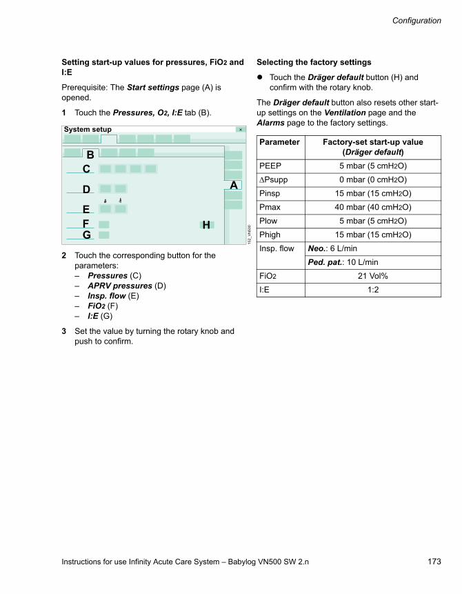
Instructions for use Infinity Acute Care System – Babylog VN500 SW 2.n 173
Configuration
Setting start-up values for pressures, FiO2 and I:E
Prerequisite: The Start settings page (A) is opened.
1 Touch the Pressures, O2, I:E tab (B).
2 Touch the corresponding button for the parameters:– Pressures (C)– APRV pressures (D)– Insp. flow (E)– FiO2 (F)– I:E (G)
3 Set the value by turning the rotary knob and push to confirm.
Selecting the factory settings
Touch the Dräger default button (H) and confirm with the rotary knob.
The Dräger default button also resets other start-up settings on the Ventilation page and the Alarms page to the factory settings.
15
2_
VN
50
0
System setup
A
B
H
C
D
FG
E
Parameter Factory-set start-up value(Dräger default)
PEEP 5 mbar (5 cmH2O)
Psupp 0 mbar (0 cmH2O)
Pinsp 15 mbar (15 cmH2O)
Pmax 40 mbar (40 cmH2O)
Plow 5 mbar (5 cmH2O)
Phigh 15 mbar (15 cmH2O)
Insp. flow Neo.: 6 L/min
Ped. pat.: 10 L/min
FiO2 21 Vol%
I:E 1:2
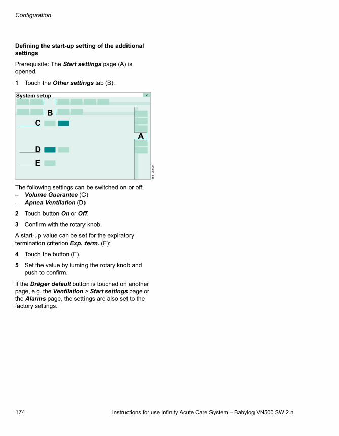
Configuration
174 Instructions for use Infinity Acute Care System – Babylog VN500 SW 2.n
Defining the start-up setting of the additional settings
Prerequisite: The Start settings page (A) is opened.
1 Touch the Other settings tab (B).
The following settings can be switched on or off:– Volume Guarantee (C) – Apnea Ventilation (D)
2 Touch button On or Off.
3 Confirm with the rotary knob.
A start-up value can be set for the expiratory termination criterion Exp. term. (E):
4 Touch the button (E).
5 Set the value by turning the rotary knob and push to confirm.
If the Dräger default button is touched on another page, e.g. the Ventilation > Start settings page or the Alarms page, the settings are also set to the factory settings.
15
3_
VN
50
0
System setup
A
BC
D
E
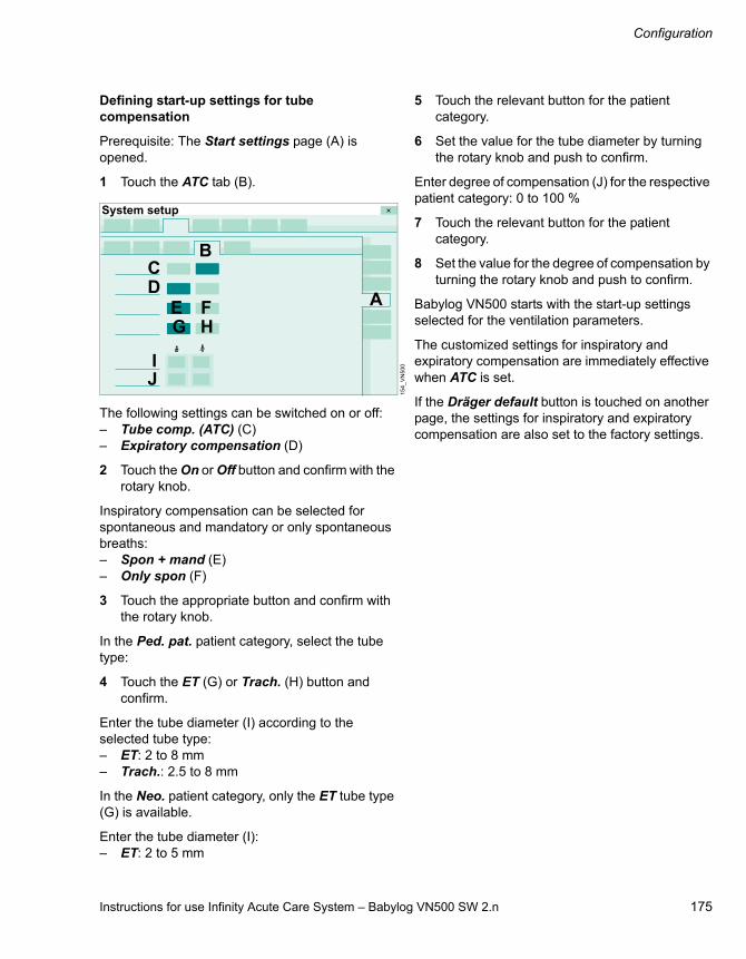
Instructions for use Infinity Acute Care System – Babylog VN500 SW 2.n 175
Configuration
Defining start-up settings for tube compensation
Prerequisite: The Start settings page (A) is opened.
1 Touch the ATC tab (B).
The following settings can be switched on or off:– Tube comp. (ATC) (C) – Expiratory compensation (D)
2 Touch the On or Off button and confirm with the rotary knob.
Inspiratory compensation can be selected for spontaneous and mandatory or only spontaneous breaths:– Spon + mand (E)– Only spon (F)
3 Touch the appropriate button and confirm with the rotary knob.
In the Ped. pat. patient category, select the tube type:
4 Touch the ET (G) or Trach. (H) button and confirm.
Enter the tube diameter (I) according to the selected tube type:– ET: 2 to 8 mm– Trach.: 2.5 to 8 mm
In the Neo. patient category, only the ET tube type (G) is available.
Enter the tube diameter (I):– ET: 2 to 5 mm
5 Touch the relevant button for the patient category.
6 Set the value for the tube diameter by turning the rotary knob and push to confirm.
Enter degree of compensation (J) for the respective patient category: 0 to 100 %
7 Touch the relevant button for the patient category.
8 Set the value for the degree of compensation by turning the rotary knob and push to confirm.
Babylog VN500 starts with the start-up settings selected for the ventilation parameters.
The customized settings for inspiratory and expiratory compensation are immediately effective when ATC is set.
If the Dräger default button is touched on another page, the settings for inspiratory and expiratory compensation are also set to the factory settings.
15
4_
VN
50
0
System setup
A
BCD
H
IJ
E FG

Configuration
176 Instructions for use Infinity Acute Care System – Babylog VN500 SW 2.n
Defining start-up settings for high-frequency oscillation (HFO)
Prerequisite: The Start settings page (A) is opened.
1 Touch the HFO tab (B).
2 Touch the corresponding button for the parameters:– VThf (C)– fhf (D)– I:Ehf (E)– Ampl hf (F)
3 Set the value by turning the rotary knob and push to confirm.
31
4_
VN
50
0
System setup
A
BC
D
E
F

Instructions for use Infinity Acute Care System – Babylog VN500 SW 2.n 177
Configuration
Configuring general settings
Prerequisite: The Ventilation page (A) is opened.
1 Touch the General settings tab (B).
The following settings can be switched on or off:– Leakage Compensation (C) – Automatic return from Apnea Ventilation (D)– Apnea Ventilation alarm (E)– Pmax/Paw high autoset (F)– Anti Air Shower (G)
2 Touch the On or Off button as appropriate and confirm with the rotary knob.
Select Slope adjustment (H): – Slope (I)– Insp. flow (J)
3 Touch the appropriate button and confirm with the rotary knob.
Babylog VN500 starts with the selected settings.
For further information on the Anti Air Shower function, see page 321.
Setting a maneuver
Prerequisite: The Ventilation page (A) is opened.
1 Touch the Maneuver tab (B).
Setting the FiO2 concentration for the suction maneuver
For the suction maneuver, FiO2 is set based on the current FiO2 concentration using a factor between 1.0 and 2.0.
2 Touch button (C) or (D).
3 Set the factor by turning the rotary knob and push to confirm.
Babylog VN500 starts with the selected start-up settings.
15
6_
VN
50
0
System setup
A
B
CHDE
I J
G
F
15
5_
VN
50
0
System setup
A
B
C D
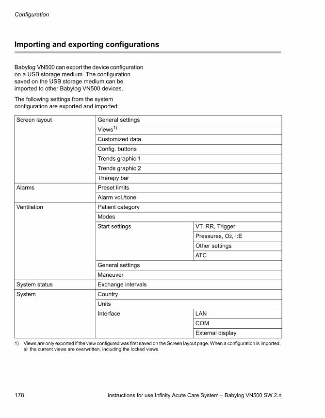
Configuration
178 Instructions for use Infinity Acute Care System – Babylog VN500 SW 2.n
Importing and exporting configurations
Babylog VN500 can export the device configuration on a USB storage medium. The configuration saved on the USB storage medium can be imported to other Babylog VN500 devices.
The following settings from the system configuration are exported and imported:
Screen layout General settings
Views1)
1) Views are only exported if the view configured was first saved on the Screen layout page. When a configuration is imported, all the current views are overwritten, including the locked views.
Customized data
Config. buttons
Trends graphic 1
Trends graphic 2
Therapy bar
Alarms Preset limits
Alarm vol./tone
Ventilation Patient category
Modes
Start settings VT, RR, Trigger
Pressures, O2, I:E
Other settings
ATC
General settings
Maneuver
System status Exchange intervals
System Country
Units
Interface LAN
COM
External display

Instructions for use Infinity Acute Care System – Babylog VN500 SW 2.n 179
Configuration
Preparing the configuration exchange
Insert the USB storage medium into a USB port on Infinity C500.
1 Touch the System setup... button in the main menu bar.
2 Touch the Config. exchange tab (A).
Importing a configuration from a USB storage medium to the device
A configuration can only be imported in standby mode.
1 Switch Babylog VN500 to standby mode.
2 Select a configuration from the USB storage medium (C).
3 Touch the Import button (E).
4 Confirm with the rotary knob.
If there is no valid configuration saved on the USB storage medium, the system issues a message.
After the import, Babylog VN500 is switched off automatically.
5 Switch Babylog VN500 on again.
Babylog VN500 reports the completion of the configuration with a low-priority alarm.
6 Check the settings of the imported configuration.
Exporting a configuration from the device to a USB storage medium
1 Touch the Export button (F).
2 Confirm with the rotary knob.
If the USB storage medium already contains a configuration, a message appears stating that this configuration will be overwritten.
No export is possible onto the USB storage medium if it is full. The Export button (F) is grayed out and cannot be activated.
15
7
B Configuration on the device with the date of export
C Existing configurations on the USB storage medium
D Selected configuration on the USB storage medium with the date of export
System setup
A
B DFE
C
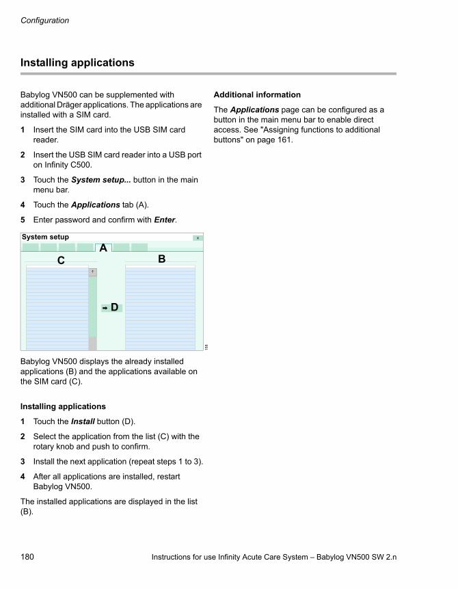
Configuration
180 Instructions for use Infinity Acute Care System – Babylog VN500 SW 2.n
Installing applications
Babylog VN500 can be supplemented with additional Dräger applications. The applications are installed with a SIM card.
1 Insert the SIM card into the USB SIM card reader.
2 Insert the USB SIM card reader into a USB port on Infinity C500.
3 Touch the System setup... button in the main menu bar.
4 Touch the Applications tab (A).
5 Enter password and confirm with Enter.
Babylog VN500 displays the already installed applications (B) and the applications available on the SIM card (C).
Installing applications
1 Touch the Install button (D).
2 Select the application from the list (C) with the rotary knob and push to confirm.
3 Install the next application (repeat steps 1 to 3).
4 After all applications are installed, restart Babylog VN500.
The installed applications are displayed in the list (B).
Additional information
The Applications page can be configured as a button in the main menu bar to enable direct access. See "Assigning functions to additional buttons" on page 161.
15
8
AC B
System setup
D
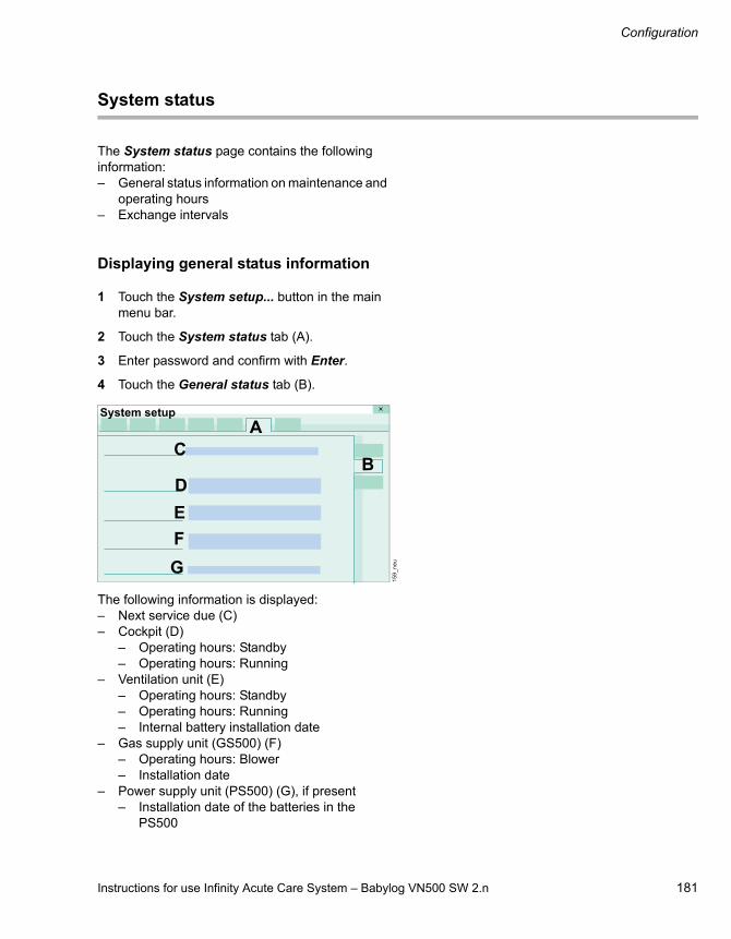
Instructions for use Infinity Acute Care System – Babylog VN500 SW 2.n 181
Configuration
System status
The System status page contains the following information:– General status information on maintenance and
operating hours– Exchange intervals
Displaying general status information
1 Touch the System setup... button in the main menu bar.
2 Touch the System status tab (A).
3 Enter password and confirm with Enter.
4 Touch the General status tab (B).
The following information is displayed:– Next service due (C)– Cockpit (D)
– Operating hours: Standby– Operating hours: Running
– Ventilation unit (E)– Operating hours: Standby– Operating hours: Running– Internal battery installation date
– Gas supply unit (GS500) (F)– Operating hours: Blower– Installation date
– Power supply unit (PS500) (G), if present– Installation date of the batteries in the
PS500
15
9_
ne
u
System setup
A
BC
D
E
F
G

Configuration
182 Instructions for use Infinity Acute Care System – Babylog VN500 SW 2.n
Configuring exchange intervals
The user can configure how much of the period of use elapses before Babylog VN500 displays a message indicating that the next exchange of an accessory is due. This depends on the device type and software version.
The exchange interval must be defined in accordance with the applicable hygiene guidelines or in accordance with the specifications of the corresponding accessory's instructions for use.
Opening the exchange interval page
1 Touch the System setup... button in the main menu bar.
2 Touch the System status tab (A).
3 Enter password and confirm with Enter.
4 Touch the Exchange intervals tab (B).
The exchange interval and the service life already elapsed for the accessory (C) are displayed.
Setting the exchange intervals
5 Touch the button (D).
6 Set the value by turning the rotary knob and push to confirm.
The settings are effective immediately.
No display of exchange intervals
Touch the button (D). Set Off by turning the rotary knob and push to confirm.
Additional information
Babylog VN500 displays the remaining period of use for the accessories on the Start/Standby > Accessory status page.
Sterilization of the expiratory valve or inspiratory valve may gradually impair the operation of RFID transmission. This may mean that Infinity ID breathing circuit functions may not work or may no longer work reliably. The period of use for the Infinity ID accessories is displayed with ---.
WARNING
Risk of inappropriate operating life
Exchange monitoring only considers the actual period of use and not the current status of the Infinity ID accessory and therefore does not release the user from the responsibility of periodically checking the accessory.
The exchange interval set for exchange monitoring does not guarantee that the accessory will last until the exchange interval has expired.
15
9_
VN
50
0
System setup
A
B
C D

Instructions for use Infinity Acute Care System – Babylog VN500 SW 2.n 183
Configuration
System settings
The following system settings can be configured:– Country– Units– Interface (interfaces)– Supply units (supply units)– Service
The customized settings are immediately effective.
1 Touch the System setup... button.
2 Touch the System tab.
Babylog VN500 displays the following configurable settings in an overview:– Language, date and time– Units for measured values and settings– Network and serial interfaces– GS500– Service information
Selecting country-specific settings
Prerequisite: The System page (A) is opened.
1 Touch the Country tab (B).
Selecting the screen text language
Babylog VN500 is factory set to the customer's own language. The current language is displayed in the field (C).
Selecting a different language:
2 Touch the button (D).
Babylog VN500 opens the selection list containing the available languages.
3 Select the language with the rotary knob and push to confirm.
Setting the date and time
Babylog VN500 does not change over automatically between daylight saving time and standard time. The user must change the time manually. Otherwise the times will be incorrect on the screen and for saved values and actions (e.g., in the logbook).
Changing the system time changes the time displayed in trends, logbook, alarm history, maneuver measured values and reference loops. The data saved up to the change is displayed with the system time up till then.
1 Touch the appropriate button:– Day (E)– Month (F)– Year (G)– Hours (H)– Minutes (I)
The order of the buttons (E) and (F) varies depending on language.
2 Set the value by turning the rotary knob and push to confirm.
3 After completing all the settings for the date and time, touch the Apply button (J).
16
0
:
System setup
A
BC D
H
K
JE F G
I

Configuration
184 Instructions for use Infinity Acute Care System – Babylog VN500 SW 2.n
Entering the height above sea level
The ambient pressure is considered in the calculation of measured values. The ambient pressure sensor is checked for plausibility using the entered height above sea level. Incorrect entries can mean that the ambient pressure sensor is recognized as incorrect.
1 Touch the button (K).
2 Set the height by turning the rotary knob and push to confirm.
Configuring units
Prerequisite: The System page (A) is opened.
1 Touch the Units tab (B).
The units for the following parameters can be selected.– Airway pressure (C) in mbar or cmH2O– Height (D) in m, cm or feet, inch– CO2 (E) in Vol% or mmHg or kPa
The unit selected for the CO2 measured value is adopted for the alarm limit.
2 Touch the relevant button for the unit.
16
1
System setup
A
B
C
D
E
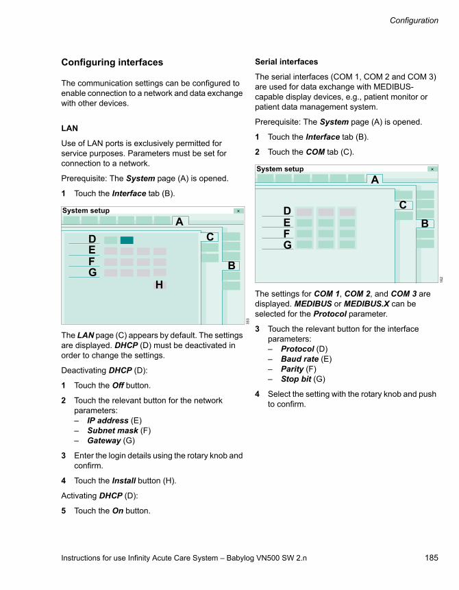
Instructions for use Infinity Acute Care System – Babylog VN500 SW 2.n 185
Configuration
Configuring interfaces
The communication settings can be configured to enable connection to a network and data exchange with other devices.
LAN
Use of LAN ports is exclusively permitted for service purposes. Parameters must be set for connection to a network.
Prerequisite: The System page (A) is opened.
1 Touch the Interface tab (B).
The LAN page (C) appears by default. The settings are displayed. DHCP (D) must be deactivated in order to change the settings.
Deactivating DHCP (D):
1 Touch the Off button.
2 Touch the relevant button for the network parameters:– IP address (E)– Subnet mask (F)– Gateway (G)
3 Enter the login details using the rotary knob and confirm.
4 Touch the Install button (H).
Activating DHCP (D):
5 Touch the On button.
Serial interfaces
The serial interfaces (COM 1, COM 2 and COM 3) are used for data exchange with MEDIBUS-capable display devices, e.g., patient monitor or patient data management system.
Prerequisite: The System page (A) is opened.
1 Touch the Interface tab (B).
2 Touch the COM tab (C).
The settings for COM 1, COM 2, and COM 3 are displayed. MEDIBUS or MEDIBUS.X can be selected for the Protocol parameter.
3 Touch the relevant button for the interface parameters:– Protocol (D)– Baud rate (E)– Parity (F)– Stop bit (G)
4 Select the setting with the rotary knob and push to confirm.
35
3
System setup
A
B
CDEFG
H 16
2
System setup
A
B
CDEFG

Configuration
186 Instructions for use Infinity Acute Care System – Babylog VN500 SW 2.n
External screen
If a second screen is connected to Infinity C500, the user has to define whether the screen is analog or digital.
Prerequisite: The System page (A) is opened.
1 Touch the Interface tab (B).
2 Touch the External display tab (C).
3 Touch the Digital (D) or Analog (E) button.
Additional information
The serial interface connectors are located on the rear of Infinity C500.
Configuring supply units
Functionality of the GS500 gas supply unit
The functionality of the gas supply unit can be deactivated if Babylog VN500 is equipped with a gas supply unit that is currently not supposed to be used.
Prerequisite: The System page (A) is opened.
Touch the Supply units tab (B).
Touch the Off button (C).
The gas supply unit is no longer available. In the device check, the system does not display the Gas supply unit test step.
Activating the functionality of the gas supply unit:
1 Touch the On button (D).
Babylog VN500 displays in the message field (E) that the device check has to be carried out.
2 Perform device check.
Additional information
For information on using the gas supply unit, see "GS500 gas supply unit" on page 110.
32
0
System setup
A
BC
D E
32
6
System setup
A
B
D C
E

Instructions for use Infinity Acute Care System – Babylog VN500 SW 2.n 187
Configuration
Service dialog
The service dialog is password-protected and reserved for DrägerService or experts.
For further information on Remote Service, see chapter "Remote Service" on page 249.

188 Instructions for use Infinity Acute Care System – Babylog VN500 SW 2.n
This page has been left blank intentionally.

Instructions for use Infinity Acute Care System – Babylog VN500 SW 2.n 189
Alarm – Cause – Remedy
Alarm – Cause – Remedy
The alarm messages are displayed in the message field of the header bar in hierarchical order. See "Display of alarms" on page 124.
In order to classify the alarms within an alarm category, internal priority numbers are given after the exclamation marks in the table below. The most critical alarm is awarded the number 255. The priority of the alarm decreases the lower the number is.
In the following table, the alarm messages are listed in alphabetical order. If an alarm occurs, the table helps to identify causes and remedies. The different causes and remedies should be worked through in the order listed until the alarm has been resolved.
The acknowledgeable alarm messages can be found in the chapter "Alarm – Cause – Remedy". For alarm messages that can be acknowledged, the "Remedy" column in the table contains information stating that the alarm message can be acknowledged by pressing the ALARM RESET button and confirming with the rotary knob.
The following alarm messages that can be acknowledged are not listed:
– Suction maneuver overused?
– PEEP high (!!)

Alarm – Cause – Remedy
190 Instructions for use Infinity Acute Care System – Babylog VN500 SW 2.n
Alarm priority
Alarm message Cause Remedy
! 060 Accessory ID detection failed
Accessory ID detection malfunction.
Ventilation can be started without ID functions.
Call DrägerService.
!! 110 Air and O2 supply insufficient
Air and O2 supply insufficient to deliver required flow and pressure for HFO.
Check connections to Air and O2 supply.
Make sure supply pressures are greater than 3 bar (43.5 psi).
Downgrade alarm priority by touching "ALARM RESET" button and confirm with rotary knob.
!! 110 Air pressure regulation failed
Internal Air supply pressure too high.
Air pressure regulator failure.
No HFO possible.
Call DrägerService.
!! 110 Air supply insufficient
Air supply insufficient to deliver required flow and pressure for HFO.
Driver gas for active expiration during HFO is O2 only.
Check connection to Air supply.
Make sure that the supply pressure is greater than 3 bar (43.5 psi).
Acknowledge message by touching "ALARM RESET" and confirm.
Use external O2 monitoring.
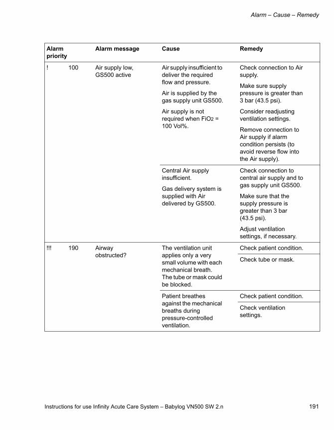
Instructions for use Infinity Acute Care System – Babylog VN500 SW 2.n 191
Alarm – Cause – Remedy
! 100 Air supply low, GS500 active
Air supply insufficient to deliver the required flow and pressure.
Air is supplied by the gas supply unit GS500.
Air supply is not required when FiO2 = 100 Vol%.
Check connection to Air supply.
Make sure supply pressure is greater than 3 bar (43.5 psi).
Consider readjusting ventilation settings.
Remove connection to Air supply if alarm condition persists (to avoid reverse flow into the Air supply).
Central Air supply insufficient.
Gas delivery system is supplied with Air delivered by GS500.
Check connection to central air supply and to gas supply unit GS500.
Make sure that the supply pressure is greater than 3 bar (43.5 psi).
Adjust ventilation settings, if necessary.
!!! 190 Airway obstructed?
The ventilation unit applies only a very small volume with each mechanical breath. The tube or mask could be blocked.
Check patient condition.
Check tube or mask.
Patient breathes against the mechanical breaths during pressure-controlled ventilation.
Check patient condition.
Check ventilation settings.
Alarm priority
Alarm message Cause Remedy

Alarm – Cause – Remedy
192 Instructions for use Infinity Acute Care System – Babylog VN500 SW 2.n
!!! 205 Airway pressure high
Breathing hose kinked. Check breathing circuit.
Check tube or mask.
The upper alarm limit for the airway pressure has been exceeded. The patient is breathing against the ventilation unit or coughing.
Check patient condition.
Check ventilation settings.
Adjust alarm limit if necessary.
!!! 200 Airway pressure low
Leakage or disconnection.
Check breathing circuit for tight connections.
Check whether the expiratory valve is properly engaged.
Make sure that the tube or mask is connected correctly.
!!! 140 Airway pressure negative
Airway pressure has fallen below –10 mbar (–10 cmH2O).
Disconnect tube for suctioning.
Check patient condition.
Check ventilation settings.
The breathing hose is connected to the expiratory valve during O2 therapy.
Connect breathing hose to the inspiratory valve.
!!! 140 Airway pressure negative (averaged)
Average airway pressure has fallen below –2 mbar (–2 cmH2O).
Disconnect tube for suctioning.
Check patient condition.
Check ventilation settings.
!! 140 Airway pressure negative (averaged)
Average airway pressure has fallen below –2 mbar (–2 cmH2O).
Disconnect tube for suctioning.
Check patient condition.
Check ventilation settings.
Alarm priority
Alarm message Cause Remedy

Instructions for use Infinity Acute Care System – Babylog VN500 SW 2.n 193
Alarm – Cause – Remedy
! 200 Alarm limit not confirmed
One or more alarm limits have been changed but not confirmed.
If necessary, change these alarm limits and confirm the change with the rotary knob.
! 120 Alarm system failure
Failure of primary alarm speaker.
In case of an alarm situation, the auxiliary acoustical alarm will sound.
To continue ventilation with this device, continuously monitor the device functions.
Call DrägerService.
!! 100 Ambient pressure sensor?
Altitude setting deviates too much from measured ambient pressure.
Check altitude setting and adjust if necessary.
If the setting has been adjusted, the device check must be repeated.
Ambient pressure sensor failure.
Accuracy of measured values depending on the atmospheric pressure could be impaired (e.g., MV, O2 concentration).
Call DrägerService.
!!! 181 Apnea The patient has stopped breathing.
Check patient condition.
Apply controlled ventilation if necessary.
Obstruction. Check patient condition.
Check breathing circuit.
Check tube or mask.
Flow sensor is not calibrated or faulty.
Calibrate flow sensor and replace it if necessary.
Alarm priority
Alarm message Cause Remedy

Alarm – Cause – Remedy
194 Instructions for use Infinity Acute Care System – Babylog VN500 SW 2.n
!! 230 Apnea Ventilation Due to detected apnea, the ventilation unit has automatically switched to Apnea Ventilation.
Check patient condition.
Check tube or mask.
Check ventilation settings and patient condition. Return to the original ventilation mode by touching the "Apn. Vent. reset" button and confirm with rotary knob.
! 020 Application already installed
Application is already installed.
Acknowledge message by touching "ALARM RESET" button and confirm with rotary knob.
! 020 Application transfer failed
Invalid application. Acknowledge message by touching "ALARM RESET" button and confirm with rotary knob.
Call DrägerService.
Application installation failed.
Acknowledge message by touching "ALARM RESET" button and confirm with rotary knob.
Call DrägerService.
!! 050 "Audio paused" key used too often
The "Audio paused" key is either faulty or was pressed more than 80 times per hour.
The function of the "Audio paused" key is not available while the defect exists.
If the defect cannot be remedied, call DrägerService.
!! 050 "Audio paused" overused or stuck
The "Audio paused" button is either stuck or faulty or was pressed for more than 6 seconds.
Ventilation functions are not affected.
Do not press the "Audio paused" button longer than 6 seconds.
If the error persists, call DrägerService.
Alarm priority
Alarm message Cause Remedy
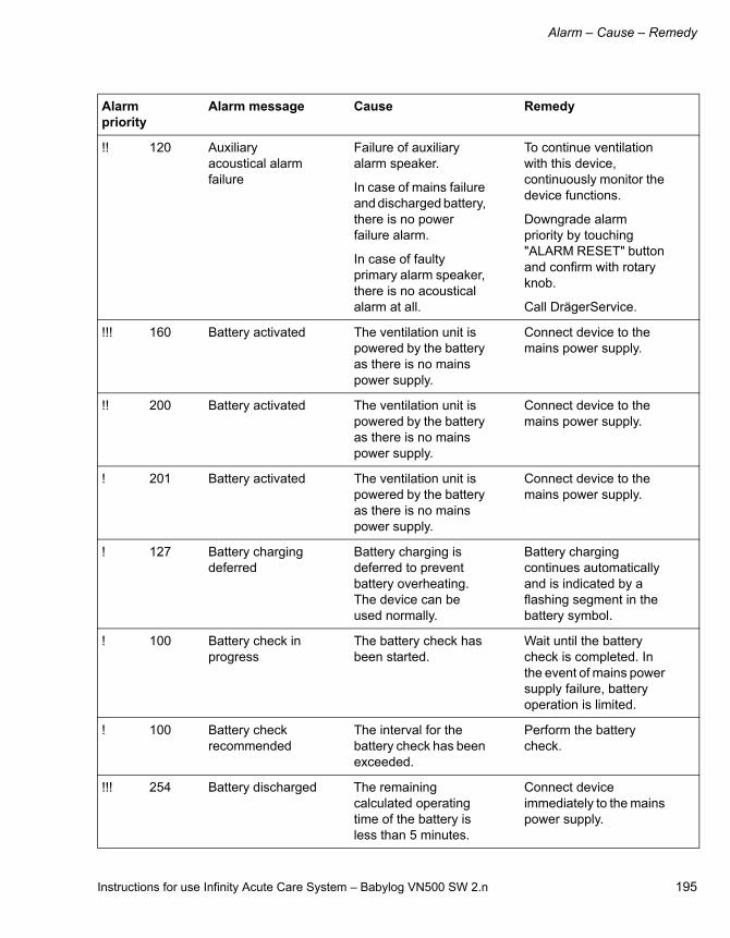
Instructions for use Infinity Acute Care System – Babylog VN500 SW 2.n 195
Alarm – Cause – Remedy
!! 120 Auxiliary acoustical alarm failure
Failure of auxiliary alarm speaker.
In case of mains failure and discharged battery, there is no power failure alarm.
In case of faulty primary alarm speaker, there is no acoustical alarm at all.
To continue ventilation with this device, continuously monitor the device functions.
Downgrade alarm priority by touching "ALARM RESET" button and confirm with rotary knob.
Call DrägerService.
!!! 160 Battery activated The ventilation unit is powered by the battery as there is no mains power supply.
Connect device to the mains power supply.
!! 200 Battery activated The ventilation unit is powered by the battery as there is no mains power supply.
Connect device to the mains power supply.
! 201 Battery activated The ventilation unit is powered by the battery as there is no mains power supply.
Connect device to the mains power supply.
! 127 Battery charging deferred
Battery charging is deferred to prevent battery overheating. The device can be used normally.
Battery charging continues automatically and is indicated by a flashing segment in the battery symbol.
! 100 Battery check in progress
The battery check has been started.
Wait until the battery check is completed. In the event of mains power supply failure, battery operation is limited.
! 100 Battery check recommended
The interval for the battery check has been exceeded.
Perform the battery check.
!!! 254 Battery discharged The remaining calculated operating time of the battery is less than 5 minutes.
Connect device immediately to the mains power supply.
Alarm priority
Alarm message Cause Remedy

Alarm – Cause – Remedy
196 Instructions for use Infinity Acute Care System – Babylog VN500 SW 2.n
!! 120 Battery failure Battery operation is not available in the event of mains power supply failure.
To continue ventilation with this device, continuously monitor the device functions.
Call DrägerService.
!!! 250 Battery low The remaining calculated operating time of the battery is less than 10 minutes.
Connect device to the mains power supply.
!! 251 Battery low The remaining calculated operating time of the battery is less than 10 minutes.
Connect device to the mains power supply.
!! 105 Breath. circ. does not fit to patient category
Connected breathing circuit does not fit to selected patient category.
Use suitable breathing circuit or select correct patient category.
!! 100 Breathing circuit does not match config.
Breathing circuit has been exchanged. The new breathing circuit does not match the one that was used before.
Check breathing circuit.
Acknowledge message by pressing "ALARM RESET" and confirm.
! 060 Breathing circuit ID invalid
Accessory ID detection failed.
No automatic adjustment of breathing circuit properties.
Replace ID Breathing Circuit or perform breathing circuit check.
Acknowledge message by touching "ALARM RESET" button and confirm with rotary knob.
Accessory ID detection failed.
Breathing circuit exchange interval cannot be monitored.
Replace Infinity ID Breathing Circuit
or
acknowledge message by touching "ALARM RESET" button and confirm with rotary knob.
Alarm priority
Alarm message Cause Remedy

Instructions for use Infinity Acute Care System – Babylog VN500 SW 2.n 197
Alarm – Cause – Remedy
!! 205 Breathing hose kinked
The pressure at the inspiratory port is greater than 30 mbar (30 cmH2O), e.g., due to a kinked or blocked hose, or a blocked mask.
Check breathing circuit.
Check mask.
!! 105 Breathing hoses interchanged
Inspiratory and expiratory limbs of the breathing circuit are connected reversely to the ventilation unit.
Connect inspiratory and expiratory limbs of the breathing circuit correctly.
!!! 240 Calibration of gas delivery system required
Technical malfunction detected during operation.
Calibration of gas delivery system failed.
Recalibration necessary.
Ventilation not possible.
Disconnect patient from the device and continue ventilation without delay using another independent ventilator.
Perform device check.
Alarm priority
Alarm message Cause Remedy
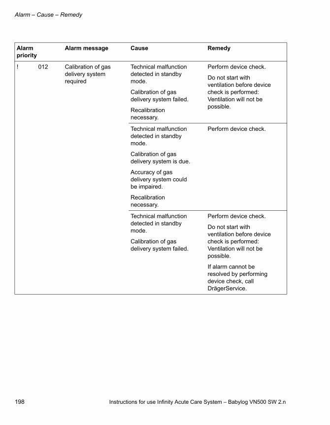
Alarm – Cause – Remedy
198 Instructions for use Infinity Acute Care System – Babylog VN500 SW 2.n
! 012 Calibration of gas delivery system required
Technical malfunction detected in standby mode.
Calibration of gas delivery system failed.
Recalibration necessary.
Perform device check.
Do not start with ventilation before device check is performed: Ventilation will not be possible.
Technical malfunction detected in standby mode.
Calibration of gas delivery system is due.
Accuracy of gas delivery system could be impaired.
Recalibration necessary.
Perform device check.
Technical malfunction detected in standby mode.
Calibration of gas delivery system failed.
Perform device check.
Do not start with ventilation before device check is performed: Ventilation will not be possible.
If alarm cannot be resolved by performing device check, call DrägerService.
Alarm priority
Alarm message Cause Remedy
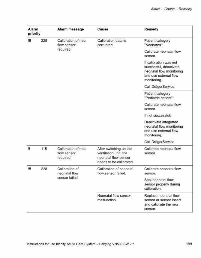
Instructions for use Infinity Acute Care System – Babylog VN500 SW 2.n 199
Alarm – Cause – Remedy
!!! 228 Calibration of neo. flow sensor required
Calibration data is corrupted.
Patient category "Neonates":
Calibrate neonatal flow sensor.
If calibration was not successful, deactivate neonatal flow monitoring and use external flow monitoring.
Call DrägerService.
Patient category "Pediatric patient":
Calibrate neonatal flow sensor.
If not successful:
Deactivate integrated neonatal flow monitoring and use external flow monitoring.
Call DrägerService.
!! 115 Calibration of neo. flow sensor required
After switching on the ventilation unit, the neonatal flow sensor needs to be calibrated.
Calibrate neonatal flow sensor.
!!! 228 Calibration of neonatal flow sensor failed
Calibration of neonatal flow sensor failed.
Calibrate neonatal flow sensor.
Seal neonatal flow sensor properly during calibration.
Neonatal flow sensor malfunction.
Replace neonatal flow sensor or sensor insert and calibrate the new sensor.
Alarm priority
Alarm message Cause Remedy
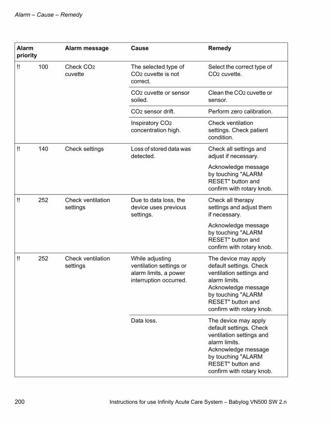
Alarm – Cause – Remedy
200 Instructions for use Infinity Acute Care System – Babylog VN500 SW 2.n
!! 100 Check CO2 cuvette
The selected type of CO2 cuvette is not correct.
Select the correct type of CO2 cuvette.
CO2 cuvette or sensor soiled.
Clean the CO2 cuvette or sensor.
CO2 sensor drift. Perform zero calibration.
Inspiratory CO2 concentration high.
Check ventilation settings. Check patient condition.
!! 140 Check settings Loss of stored data was detected.
Check all settings and adjust if necessary.
Acknowledge message by touching "ALARM RESET" button and confirm with rotary knob.
!! 252 Check ventilation settings
Due to data loss, the device uses previous settings.
Check all therapy settings and adjust them if necessary.
Acknowledge message by touching "ALARM RESET" button and confirm with rotary knob.
!! 252 Check ventilation settings
While adjusting ventilation settings or alarm limits, a power interruption occurred.
The device may apply default settings. Check ventilation settings and alarm limits. Acknowledge message by touching "ALARM RESET" button and confirm with rotary knob.
Data loss. The device may apply default settings. Check ventilation settings and alarm limits. Acknowledge message by touching "ALARM RESET" button and confirm with rotary knob.
Alarm priority
Alarm message Cause Remedy

Instructions for use Infinity Acute Care System – Babylog VN500 SW 2.n 201
Alarm – Cause – Remedy
!!! 144 Clean CO2 cuvette Cuvette or sensor window is soiled, e.g. with deposits due to nebulization.
Use clean cuvette and/or clean CO2 sensor.
!!! 145 CO2 measurement failed
CO2 sensor faulty. Replace faulty CO2 sensor.
CO2 measurement incorrect.
Use external CO2 monitoring and deactivate integrated CO2 monitoring.
Call DrägerService.
!!! 146 CO2 sensor? Plug of CO2 sensor was removed during operation.
Reinsert plug.
CO2 sensor not positioned on cuvette.
Place CO2 sensor on cuvette.
CO2 sensor faulty. Replace faulty CO2 sensor.
!!! 142 CO2 zero calibration?
Zero point of the CO2 sensor is outside of the tolerance range.
Perform zero calibration.
Cuvette or sensor window is soiled, e.g. with deposits due to nebulization.
Use clean cuvette and/or clean CO2 sensor.
! 100 Cockpit restarted Internal communication error caused restart of the cockpit.
Check all therapy settings and adjust them if necessary.
Acknowledge message by touching "ALARM RESET" button and confirm with rotary knob.
! 100 Continuous nebulization activated
Continuous nebulization was activated by the user.
To end continuous nebulization, press the "Cancel" button if required.
Alarm priority
Alarm message Cause Remedy

Alarm – Cause – Remedy
202 Instructions for use Infinity Acute Care System – Babylog VN500 SW 2.n
!!! 252 Data loss Loss of stored data was detected.
To continue ventilation with this device, continuously monitor the device functions.
Downgrade alarm priority by touching "ALARM RESET" button and confirm with rotary knob.
Call DrägerService.
!! 252 Data loss Loss of stored data was detected.
To continue ventilation with this device, continuously monitor the device functions.
Downgrade alarm priority by touching "ALARM RESET" button and confirm with rotary knob.
Call DrägerService.
!! 240 Device check failed
A safety-related failure was detected during device check.
Do not use this device for ventilation therapy.
Call DrägerService.
Check assembly and position of expiratory valve.
Replace expiratory valve if required.
Do not use this device for ventilation therapy unless the device check was repeated successfully.
! 100 Device check incomplete
Device check not completely performed or partially unsuccessful.
Perform device check.
Acknowledge message by touching "ALARM RESET" button and confirm with rotary knob.
Alarm priority
Alarm message Cause Remedy
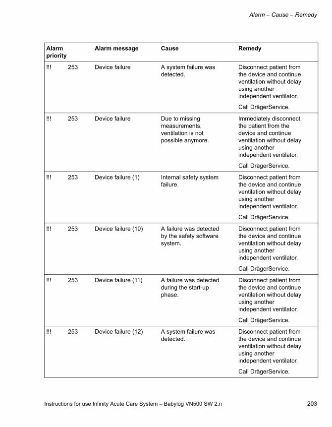
Instructions for use Infinity Acute Care System – Babylog VN500 SW 2.n 203
Alarm – Cause – Remedy
!!! 253 Device failure A system failure was detected.
Disconnect patient from the device and continue ventilation without delay using another independent ventilator.
Call DrägerService.
!!! 253 Device failure Due to missing measurements, ventilation is not possible anymore.
Immediately disconnect the patient from the device and continue ventilation without delay using another independent ventilator.
Call DrägerService.
!!! 253 Device failure (1) Internal safety system failure.
Disconnect patient from the device and continue ventilation without delay using another independent ventilator.
Call DrägerService.
!!! 253 Device failure (10) A failure was detected by the safety software system.
Disconnect patient from the device and continue ventilation without delay using another independent ventilator.
Call DrägerService.
!!! 253 Device failure (11) A failure was detected during the start-up phase.
Disconnect patient from the device and continue ventilation without delay using another independent ventilator.
Call DrägerService.
!!! 253 Device failure (12) A system failure was detected.
Disconnect patient from the device and continue ventilation without delay using another independent ventilator.
Call DrägerService.
Alarm priority
Alarm message Cause Remedy

Alarm – Cause – Remedy
204 Instructions for use Infinity Acute Care System – Babylog VN500 SW 2.n
!! 090 Device failure (13) The broken wire detection for the flow sensor is faulty.
Ventilation functions are not affected.
Call DrägerService.
!!! 253 Device failure (2) Internal safety system failure.
Do not use this device for ventilation therapy.
Call DrägerService.
!!! 253 Device failure (3) Internal communication failure.
Disconnect patient from the device and continue ventilation without delay using another independent ventilator.
Call DrägerService.
!!! 253 Device failure (4) Defective system data storage media detected.
Disconnect patient from the device and continue ventilation without delay using another independent ventilator.
Switch off the device.
Call DrägerService.
!!! 253 Device failure (5) Gas delivery system faulty.
Disconnect patient from the device and continue ventilation without delay using another independent ventilator.
Call DrägerService.
!!! 253 Device failure (6) Gas delivery system faulty.
Disconnect patient from the device and continue ventilation without delay using another independent ventilator.
Call DrägerService.
!!! 253 Device failure (7) Gas delivery system faulty.
Disconnect patient from the device and continue ventilation without delay using another independent ventilator.
Call DrägerService.
Alarm priority
Alarm message Cause Remedy

Instructions for use Infinity Acute Care System – Babylog VN500 SW 2.n 205
Alarm – Cause – Remedy
!!! 253 Device failure (8) Test alarm which should only be triggered during maintenance.
Disconnect patient from the device and continue ventilation without delay using another independent ventilator.
Call DrägerService.
!! 100 Device failure (9) No mass storage device found.
Acknowledge message by touching "ALARM RESET" button and confirm with rotary knob.
Call DrägerService.
!!! 200 Device temperature high
The internal device temperature is too high.
Disconnect patient from the device and continue ventilation without delay using another independent ventilator.
Switch off the device.
Call DrägerService.
!! 141 Device temperature measurement failed
Failure of the internal breathing-gas temperature measurement.
In case of a too high breathing-gas temperature, there is no alarm.
To continue ventilation with this device, use external breathing gas temperature monitoring.
Call DrägerService.
Failure of the internal temperature measurement.
No alarm in case of a too high device temperature.
To continue ventilation with this device, continuously monitor the device functions.
Call DrägerService.
Alarm priority
Alarm message Cause Remedy

Alarm – Cause – Remedy
206 Instructions for use Infinity Acute Care System – Babylog VN500 SW 2.n
!!! 200 Disconnection? Leakage or disconnection.
Check breathing circuit for tight connections.
Check whether the expiratory valve is properly engaged.
Make sure that the tube or mask is connected correctly.
!!! 138 etCO2 high Upper alarm limit for end-expiratory CO2 concentration has been exceeded.
Check patient condition.
Check ventilation settings.
Adjust alarm limit if necessary.
Perform CO2 zero calibration if necessary.
Check whether the cuvette windows are soiled.
!!! 138 etCO2 low Lower alarm limit for end-expiratory CO2 concentration has been exceeded.
Check patient condition.
Check ventilation settings.
Adjust alarm limit if necessary.
Perform CO2 zero calibration if necessary.
Check whether the cuvette windows are soiled.
!!! 220 Expiratory valve faulty
Expiratory valve is not properly connected to the socket.
Insert expiratory valve correctly.
Expiratory valve faulty. Replace expiratory valve.
!!! 105 Expiratory valve incompatible
Incompatible expiratory valve connected to the socket.
Replace expiratory valve.
Alarm priority
Alarm message Cause Remedy

Instructions for use Infinity Acute Care System – Babylog VN500 SW 2.n 207
Alarm – Cause – Remedy
!! 100 Expiratory valve incompatible
Incompatible expiratory valve connected to the socket.
Replace expiratory valve.
!!! 130 FiO2 high O2 sensor is not calibrated.
Calibrate O2 sensor.
Mixer function faulty. Call DrägerService.
!!! 130 FiO2 low O2 sensor is not calibrated.
Calibrate O2 sensor.
Mixer function faulty. Call DrägerService.
!! 100 Flow measurement inaccurate
Flow sensor is not calibrated or faulty.
Calibrate flow sensor and replace it if necessary.
Water in flow sensor. Drain water trap of breathing circuit. Dry flow sensor.
Flow measurement is not reliable. Expiratory minute volume exceeds minute volume delivered by the ventilation unit.
To continue ventilation with this device, use external flow monitoring and deactivate integrated flow monitoring.
This could impair the quality of ventilation.
Call DrägerService.
!!! 110 GS500 communication failure
Communication to gas supply unit GS500 lost.
Check communication connection to gas supply unit GS500.
Acknowledge message by pressing "ALARM RESET" and confirm.
Call DrägerService.
Alarm priority
Alarm message Cause Remedy
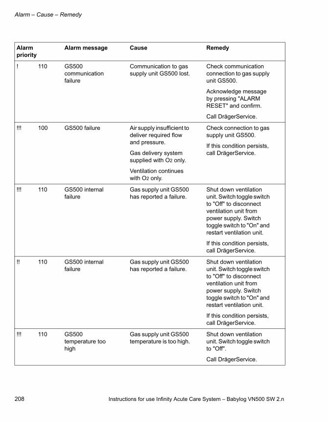
Alarm – Cause – Remedy
208 Instructions for use Infinity Acute Care System – Babylog VN500 SW 2.n
! 110 GS500 communication failure
Communication to gas supply unit GS500 lost.
Check communication connection to gas supply unit GS500.
Acknowledge message by pressing "ALARM RESET" and confirm.
Call DrägerService.
!!! 100 GS500 failure Air supply insufficient to deliver required flow and pressure.
Gas delivery system supplied with O2 only.
Ventilation continues with O2 only.
Check connection to gas supply unit GS500.
If this condition persists, call DrägerService.
!!! 110 GS500 internal failure
Gas supply unit GS500 has reported a failure.
Shut down ventilation unit. Switch toggle switch to "Off" to disconnect ventilation unit from power supply. Switch toggle switch to "On" and restart ventilation unit.
If this condition persists, call DrägerService.
!! 110 GS500 internal failure
Gas supply unit GS500 has reported a failure.
Shut down ventilation unit. Switch toggle switch to "Off" to disconnect ventilation unit from power supply. Switch toggle switch to "On" and restart ventilation unit.
If this condition persists, call DrägerService.
!!! 110 GS500 temperature too high
Gas supply unit GS500 temperature is too high.
Shut down ventilation unit. Switch toggle switch to "Off".
Call DrägerService.
Alarm priority
Alarm message Cause Remedy

Instructions for use Infinity Acute Care System – Babylog VN500 SW 2.n 209
Alarm – Cause – Remedy
!!! 249 HFO not possible Gas supply unable to deliver required flow and pressure for active expiration during HFO.
Check connections to Air and O2 supply.
Make sure supply pressures are greater than 3 bar (43.5 psi).
If supply pressures are correct: Call DrägerService.
When the gas supply unit is active, change to a different ventilation mode.
! 060 ID tag of expiratory valve faulty
Accessory ID detection failed.
Expiratory valve exchange interval cannot be monitored.
Replace Infinity ID Expiratory Valve
or
acknowledge message by touching "ALARM RESET" button and confirm with rotary knob.
! 020 Import failed, check settings
Configuration import failed.
Check all settings and adjust if necessary.
Acknowledge message by touching "ALARM RESET" button and confirm with rotary knob.
! 020 Import successful, check settings
Configuration import was successful.
Check all settings and adjust if necessary.
Acknowledge message by touching "ALARM RESET" button and confirm with rotary knob.
! 150 Inspiratory hold interrupted
The "Man. insp./hold" button was pressed too long.
Release "Man. insp./hold" button.
!! 210 Internal battery activated
The batteries of PS500 are depleted. Power supply is provided by the internal battery.
Connect device to the mains power supply.
Alarm priority
Alarm message Cause Remedy

Alarm – Cause – Remedy
210 Instructions for use Infinity Acute Care System – Babylog VN500 SW 2.n
!! 120 Internal power supply failure
Technical failure detected.
To continue ventilation with this device, continuously monitor the device functions.
Call DrägerService.
! 140 Leakage Only monitored for intubated patients!
The measured relative leakage exceeds 55 %.
Check for leakages in breathing circuit.
Make sure that the tube is connected correctly.
!!! 205 Mean airway pressure high
Mean airway pressure exceeds the set value by more than 5 mbar (5 cmH2O).
Check patient condition.
Check ventilation settings.
!!! 200 Mean airway pressure low
Measured Pmean is 7 mbar (7 cmH2O) lower than set Pmean.
Check breathing circuit for tight connections.
Check whether the expiratory valve is properly engaged.
Make sure that the tube is connected correctly.
! 008 MEDIBUS communication failed
MEDIBUS communication failure.
Ventilation functions are not affected.
Check MEDIBUS connection.
Check MEDIBUS settings.
Alarm priority
Alarm message Cause Remedy

Instructions for use Infinity Acute Care System – Babylog VN500 SW 2.n 211
Alarm – Cause – Remedy
!!! 160 MV high The minute volume exceeds the upper alarm limit.
Check patient condition.
Check ventilation settings.
Adjust alarm limit if necessary.
Water in flow sensor. Drain water trap of breathing circuit. Dry flow sensor.
Flow sensor is not calibrated or faulty.
Calibrate flow sensor and replace it if necessary.
Alarm priority
Alarm message Cause Remedy

Alarm – Cause – Remedy
212 Instructions for use Infinity Acute Care System – Babylog VN500 SW 2.n
!!! 160 MV low The minute volume has fallen below the lower alarm limit.
Check patient condition.
Check ventilation settings.
Adjust alarm limit if necessary.
Obstruction. Check patient condition.
Check breathing circuit.
Check tube or mask.
Flow sensor is not calibrated or faulty.
Calibrate flow sensor and replace it if necessary.
Leakage or disconnection.
Check breathing circuit for tight connections.
Check whether the expiratory valve is properly engaged.
Make sure that the tube or mask is connected correctly.
Device failure. Disconnect patient from the device and continue ventilation without delay using another independent ventilator.
Call DrägerService.
Alarm priority
Alarm message Cause Remedy

Instructions for use Infinity Acute Care System – Babylog VN500 SW 2.n 213
Alarm – Cause – Remedy
!! 110 Nebulization canceled
Air and O2 supply insufficient to deliver required flow and pressure for nebulization.
Nebulization canceled.
Check connections to Air and O2 supply.
Make sure supply pressures are greater than 3 bar (43.5 psi).
Acknowledge message by touching "ALARM RESET" button and confirm with rotary knob.
Inspiratory flow insufficient for nebulization.
Increase inspiratory flow to more than 6 L/min for neonates and pediatric patients.
Acknowledge message by touching "ALARM RESET" button and confirm with rotary knob.
Air supply insufficient to deliver required flow and pressure for nebulization.
Check connection to Air supply.
Make sure supply pressure is greater than 3 bar (43.5 psi).
Acknowledge message by touching "ALARM RESET" button and confirm with rotary knob.
O2 supply insufficient to deliver required flow and pressure for nebulization.
Check connection to O2 supply.
Make sure supply pressure is greater than 3 bar (43.5 psi).
Acknowledge message by touching "ALARM RESET" button and confirm with rotary knob.
Alarm priority
Alarm message Cause Remedy
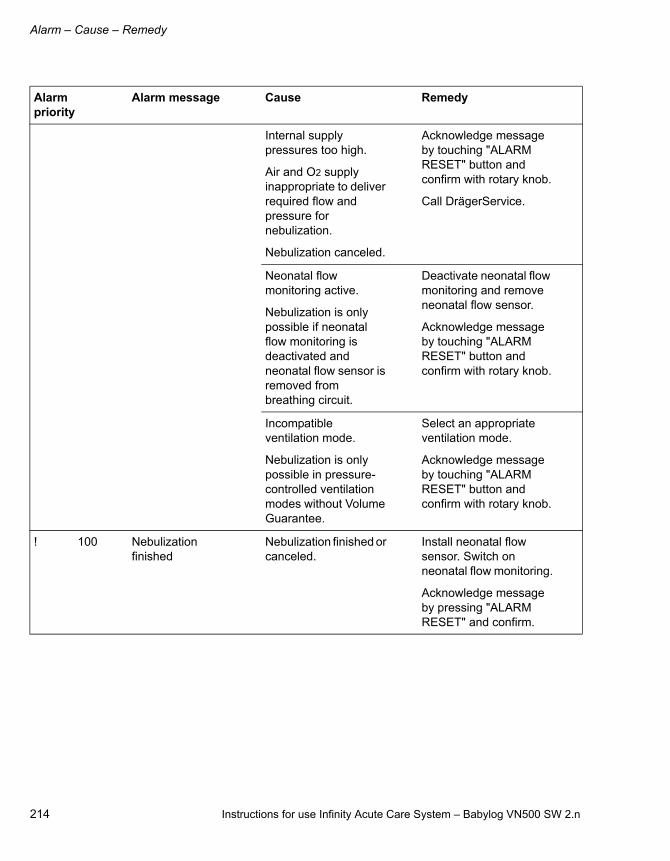
Alarm – Cause – Remedy
214 Instructions for use Infinity Acute Care System – Babylog VN500 SW 2.n
Internal supply pressures too high.
Air and O2 supply inappropriate to deliver required flow and pressure for nebulization.
Nebulization canceled.
Acknowledge message by touching "ALARM RESET" button and confirm with rotary knob.
Call DrägerService.
Neonatal flow monitoring active.
Nebulization is only possible if neonatal flow monitoring is deactivated and neonatal flow sensor is removed from breathing circuit.
Deactivate neonatal flow monitoring and remove neonatal flow sensor.
Acknowledge message by touching "ALARM RESET" button and confirm with rotary knob.
Incompatible ventilation mode.
Nebulization is only possible in pressure-controlled ventilation modes without Volume Guarantee.
Select an appropriate ventilation mode.
Acknowledge message by touching "ALARM RESET" button and confirm with rotary knob.
! 100 Nebulization finished
Nebulization finished or canceled.
Install neonatal flow sensor. Switch on neonatal flow monitoring.
Acknowledge message by pressing "ALARM RESET" and confirm.
Alarm priority
Alarm message Cause Remedy

Instructions for use Infinity Acute Care System – Babylog VN500 SW 2.n 215
Alarm – Cause – Remedy
!! 100 Nebulizer uses Air only
O2 supply insufficient to deliver required flow and pressure for nebulization.
Nebulizer is supplied with Air only.
Increased deviation from the set FiO2.
Check connection to O2 supply.
Make sure supply pressure is greater than 3 bar (43.5 psi).
Downgrade alarm priority by touching "ALARM RESET" button and confirm with rotary knob.
!! 100 Nebulizer uses O2 only
Air supply insufficient to deliver required flow and pressure for nebulization.
Nebulizer is supplied with O2 only.
Increased deviation from the set FiO2.
Check connection to Air supply.
Make sure supply pressure is greater than 3 bar (43.5 psi).
Downgrade alarm priority by touching "ALARM RESET" button and confirm with rotary knob.
Alarm priority
Alarm message Cause Remedy

Alarm – Cause – Remedy
216 Instructions for use Infinity Acute Care System – Babylog VN500 SW 2.n
!!! 228 Neonatal flow measurement failed
Neonatal flow measurement malfunction.
In case of modes with tidal volume or trigger setting:
Check ventilation settings.
Change ventilation mode if required.
Use external flow monitoring and deactivate the integrated flow monitoring.
Call DrägerService.
In case of modes without tidal volume or trigger setting:
Ventilation functions are not affected.
To continue ventilation with this device, use external flow monitoring and deactivate the integrated neonatal flow monitoring.
Call DrägerService.
Alarm priority
Alarm message Cause Remedy
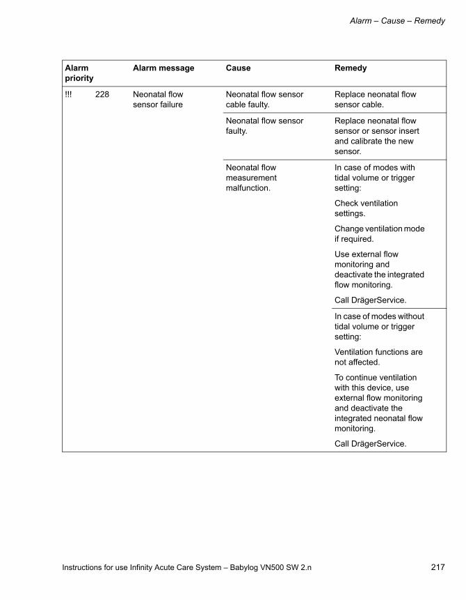
Instructions for use Infinity Acute Care System – Babylog VN500 SW 2.n 217
Alarm – Cause – Remedy
!!! 228 Neonatal flow sensor failure
Neonatal flow sensor cable faulty.
Replace neonatal flow sensor cable.
Neonatal flow sensor faulty.
Replace neonatal flow sensor or sensor insert and calibrate the new sensor.
Neonatal flow measurement malfunction.
In case of modes with tidal volume or trigger setting:
Check ventilation settings.
Change ventilation mode if required.
Use external flow monitoring and deactivate the integrated flow monitoring.
Call DrägerService.
In case of modes without tidal volume or trigger setting:
Ventilation functions are not affected.
To continue ventilation with this device, use external flow monitoring and deactivate the integrated neonatal flow monitoring.
Call DrägerService.
Alarm priority
Alarm message Cause Remedy

Alarm – Cause – Remedy
218 Instructions for use Infinity Acute Care System – Babylog VN500 SW 2.n
! 100 Neonatal flow sensor replaced?
Reconnection of the neonatal flow sensor detected.
Confirm message if calibrated neonatal flow sensor is still used.
Otherwise calibrate neonatal flow sensor.
Neonatal flow monitoring was temporarily deactivated.
Confirm message if calibrated neonatal flow sensor is still used.
Otherwise calibrate neonatal flow sensor.
!! 115 Neonatal flow sensor soiled
Water or secretion in the neonatal flow sensor.
Replace neonatal flow sensor or sensor insert and calibrate the new sensor.
!!! 229 Neonatal flow sensor?
Neonatal flow sensor is not connected.
Check connections of the neonatal flow sensor and cable.
Neonatal flow sensor malfunction.
Replace neonatal flow sensor or sensor insert and calibrate the new sensor.
!!! 140 Neonatal flow sensor?
Neonatal flow sensor not installed in the breathing circuit.
Check whether the neonatal flow sensor is fitted correctly.
Replace neonatal flow sensor if necessary.
!!! 250 No Air supply Air supply insufficient to deliver required flow and pressure.
Gas delivery system supplied with O2 only.
Ventilation continues with O2 only.
Check connection to Air supply.
Make sure supply pressure is greater than 3 bar (43.5 psi).
Consider readjusting ventilation settings.
Remove connection to Air supply if alarm condition persists (to avoid reverse flow into the Air supply).
Alarm priority
Alarm message Cause Remedy

Instructions for use Infinity Acute Care System – Babylog VN500 SW 2.n 219
Alarm – Cause – Remedy
! 100 No Air supply Air supply insufficient.
If FiO2 = 100 Vol%, Air supply is not required.
Check connection to Air supply.
Make sure supply pressure is greater than 3 bar (43.5 psi).
Consider readjusting ventilation settings.
Remove connection to Air supply if alarm condition persists (to avoid reverse flow into the Air supply).
!!! 250 No O2 supply O2 supply insufficient to deliver required flow and pressure.
Gas delivery system supplied with Air only.
Ventilation continues with Air only.
Check connection to O2 supply.
Make sure supply pressure is greater than 3 bar (43.5 psi).
Consider readjusting ventilation settings.
Remove connection to O2 supply if alarm condition persists (to avoid reverse flow into the O2 supply).
! 100 No O2 supply O2 supply insufficient.
If FiO2 = 21 Vol%, O2 supply is not required.
Check connection to O2 supply.
Make sure supply pressure is greater than 3 bar (43.5 psi).
Consider readjusting ventilation settings.
Remove connection to O2 supply if alarm condition persists (to avoid reverse flow into the O2 supply).
Alarm priority
Alarm message Cause Remedy

Alarm – Cause – Remedy
220 Instructions for use Infinity Acute Care System – Babylog VN500 SW 2.n
!! 119 Nurse call failure Technical failure detected.
To continue ventilation with this device, continuously monitor the device functions.
Call DrägerService.
!! 110 O2 and Air supply pressures differ too much
The difference between O2 supply pressure and Air supply pressure can lead to an incorrect O2 concentration during nebulization.
Check connections to Air and O2 supply.
Make sure supply pressures are greater than 3 bar (43.5 psi).
Acknowledge message by touching "ALARM RESET" button and confirm with rotary knob.
!!! 132 O2 measurement failed
O2 measurement failed.
To calibrate the O2 sensor, perform the device check.
Ventilation can be continued also if the alarm does not disappear. Use external O2 monitoring and deactivate the integrated O2 monitoring.
Call DrägerService.
!! 110 O2 pressure regulation failed
Internal O2 supply pressure too high.
O2 pressure regulator failure.
No HFO possible.
Call DrägerService.
!! 040 Oxygenation maneuver failed
Internal error during oxygenation maneuver.
Do not perform suction maneuver until the device was checked.
Call DrägerService.
Alarm priority
Alarm message Cause Remedy

Instructions for use Infinity Acute Care System – Babylog VN500 SW 2.n 221
Alarm – Cause – Remedy
!!! 140 PEEP high Expiratory valve or breathing circuit obstructed.
Check breathing circuit and expiratory valve.
Check for condensate.
Expiratory resistance increased.
Check viral/bacterial filter. Replace it if necessary.
Device failure. Disconnect patient from the device and continue ventilation without delay using another independent ventilator.
Call DrägerService.
!! 140 PEEP high Expiratory valve or breathing circuit obstructed.
Check breathing circuit and expiratory valve.
Check for condensate.
Expiratory resistance increased.
Check viral/bacterial filter. Replace it if necessary.
Device failure. Disconnect patient from the device and continue ventilation without delay using another independent ventilator.
Call DrägerService.
!!! 140 PEEP low Measured PEEP is 3 mbar (3 cmH2O) less than set PEEP.
Check breathing circuit for tight connections.
Check whether the expiratory valve is properly engaged.
Make sure that the tube or mask is connected correctly.
!! 210 Perform device and breathing circuit check
Device check and breathing circuit check must be performed before operation.
Perform device check.
Acknowledge message by touching "ALARM RESET" button and confirm with rotary knob.
Alarm priority
Alarm message Cause Remedy
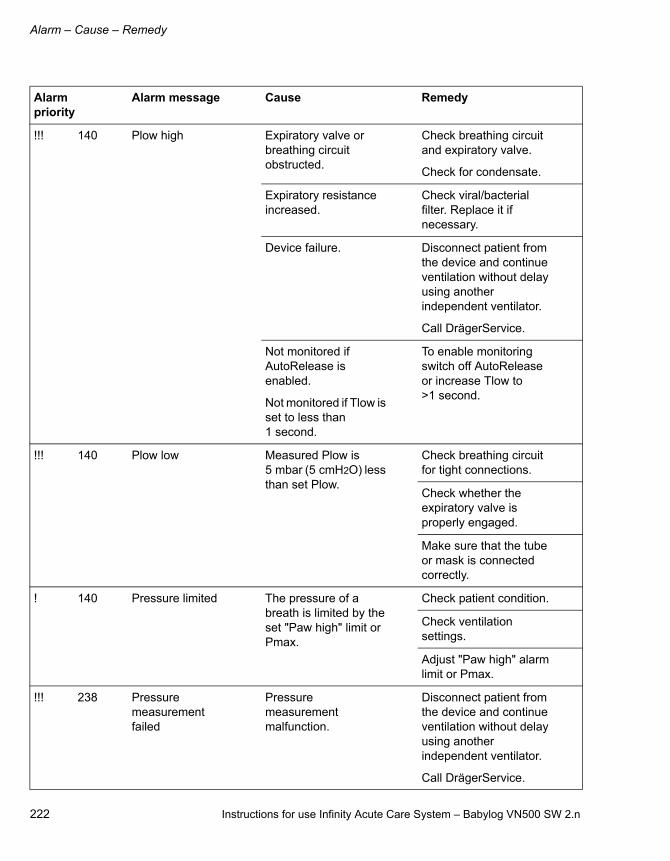
Alarm – Cause – Remedy
222 Instructions for use Infinity Acute Care System – Babylog VN500 SW 2.n
!!! 140 Plow high Expiratory valve or breathing circuit obstructed.
Check breathing circuit and expiratory valve.
Check for condensate.
Expiratory resistance increased.
Check viral/bacterial filter. Replace it if necessary.
Device failure. Disconnect patient from the device and continue ventilation without delay using another independent ventilator.
Call DrägerService.
Not monitored if AutoRelease is enabled.
Not monitored if Tlow is set to less than 1 second.
To enable monitoring switch off AutoRelease or increase Tlow to >1 second.
!!! 140 Plow low Measured Plow is 5 mbar (5 cmH2O) less than set Plow.
Check breathing circuit for tight connections.
Check whether the expiratory valve is properly engaged.
Make sure that the tube or mask is connected correctly.
! 140 Pressure limited The pressure of a breath is limited by the set "Paw high" limit or Pmax.
Check patient condition.
Check ventilation settings.
Adjust "Paw high" alarm limit or Pmax.
!!! 238 Pressure measurement failed
Pressure measurement malfunction.
Disconnect patient from the device and continue ventilation without delay using another independent ventilator.
Call DrägerService.
Alarm priority
Alarm message Cause Remedy

Instructions for use Infinity Acute Care System – Babylog VN500 SW 2.n 223
Alarm – Cause – Remedy
!! 140 Pressure measurement impaired
Pressure measurement malfunction.
Accuracy of measured values based on pressure could be impaired.
To continue ventilation with this device, continuously monitor the device functions.
Call DrägerService.
!! 100 Pressure measurement inaccurate
Fluid in expiratory valve.
Replace expiratory valve. Clean and dry used one.
Breathing circuit check has not been performed.
Perform or repeat breathing circuit check.
The inspiratory or expiratory hose is obstructed.
Check breathing circuit.
Pressure measurement failure.
Disconnect patient from the device and continue ventilation without delay using another independent ventilator.
Call DrägerService.
!! 140 Pressure sensor? Ventilation impaired
Ventilation patterns for which a pressure sensor is necessary cannot be performed. The ventilation unit applies back-up ventilation.
To continue ventilation with this device, use external pressure monitoring.
Call DrägerService.
! 100 Product test: Not for clinical use
License for product test is installed.
Call DrägerService.
Alarm priority
Alarm message Cause Remedy

Alarm – Cause – Remedy
224 Instructions for use Infinity Acute Care System – Babylog VN500 SW 2.n
!!! 150 Respiratory rate high
The patient is breathing at a high respiratory rate.
Check patient condition.
Check ventilation settings or spontaneous respiratory rate.
Adjust alarm limit if necessary.
The set respiratory rate exceeds upper alarm limit.
Adjust the respiratory rate or the upper alarm limit for the respiratory rate.
Auto triggering caused by water in the breathing circuit.
Drain water trap of breathing circuit. Dry flow sensor.
Check breathing circuit.
! 100 Restart of ventilation unit delayed
Technical failure detected. Last restart was delayed.
Downgrade alarm priority by touching "ALARM RESET" button and confirm with rotary knob.
To continue ventilation with this device, continuously monitor the device functions.
Call DrägerService.
!! 050 Rotary knob stuck or pressed too long
The rotary knob is either faulty or was pressed for more than 20 seconds without turning.
If you are still pressing the rotary knob, release it. Otherwise press and turn rotary knob repeatedly. If alarm condition persists, settings cannot be adjusted anymore.
Disconnect patient from the device and continue ventilation without delay using another independent ventilator. Call DrägerService.
Alarm priority
Alarm message Cause Remedy

Instructions for use Infinity Acute Care System – Babylog VN500 SW 2.n 225
Alarm – Cause – Remedy
!! 050 Rotary knob used too often
The rotary knob is either faulty or was pressed more than 5 times per second.
Press and turn rotary knob repeatedly.
If alarm condition persists, settings cannot be adjusted anymore.
Disconnect patient from the device and continue ventilation without delay using another independent ventilator.
Call DrägerService.
! 100 Service date approaching
Service date is almost reached.
Acknowledge message by touching "ALARM RESET" button and confirm with rotary knob.
Call DrägerService.
! 100 Service date reached
Service is due. Acknowledge message by touching "ALARM RESET" button and confirm with rotary knob.
Call DrägerService.
! 200 Setting not confirmed
One or more settings have been changed but not confirmed.
If necessary, change these settings and confirm the change with the rotary knob.
!!! 255 Standby mode activated
Device has been switched to standby mode.
Acknowledge standby mode by touching "ALARM RESET" button and confirm with rotary knob.
!! 040 Suction maneuver failed
Internal error during suction maneuver.
Do not perform suction maneuver until the device was checked.
Call DrägerService.
! 140 Suction maneuver overused?
The suction maneuver has been performed more than 5 times within an hour.
Perform suction maneuver less frequently.
Alarm priority
Alarm message Cause Remedy
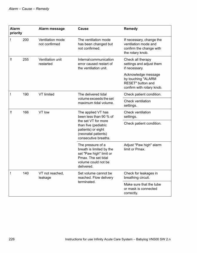
Alarm – Cause – Remedy
226 Instructions for use Infinity Acute Care System – Babylog VN500 SW 2.n
! 200 Ventilation mode not confirmed
The ventilation mode has been changed but not confirmed.
If necessary, change the ventilation mode and confirm the change with the rotary knob.
!! 255 Ventilation unit restarted
Internal communication error caused restart of the ventilation unit.
Check all therapy settings and adjust them if necessary.
Acknowledge message by touching "ALARM RESET" button and confirm with rotary knob.
! 190 VT limited The delivered tidal volume exceeds the set maximum tidal volume.
Check patient condition.
Check ventilation settings.
!! 166 VT low The applied VT has been less than 90 % of the set VT for more than five (pediatric patients) or eight (neonatal patients) consecutive breaths.
Check ventilation settings.
Check patient condition.
The pressure of a breath is limited by the set "Paw high" limit or Pmax. The set tidal volume could not be delivered.
Adjust "Paw high" alarm limit or Pmax.
! 140 VT not reached, leakage
Set volume cannot be reached. Flow delivery terminated.
Check for leakages in breathing circuit.
Make sure that the tube or mask is connected correctly.
Alarm priority
Alarm message Cause Remedy

Instructions for use Infinity Acute Care System – Babylog VN500 SW 2.n 227
Alarm – Cause – Remedy
!! 140 VThf not reached Tidal volume could not be reached due to increased resistance.
Check patient condition.
Check ventilation settings.
Tidal volume could not be reached due to pressure limitation of the device.
Reduce fhf or increase I:Ehf to 1:1.
! 100 Wrong or invalid applications found
Wrong or defective application card.
Call DrägerService.
Alarm priority
Alarm message Cause Remedy

228 Instructions for use Infinity Acute Care System – Babylog VN500 SW 2.n
This page has been left blank intentionally.

Instructions for use Infinity Acute Care System – Babylog VN500 SW 2.n 229
Reprocessing
Reprocessing
Disassembly . . . . . . . . . . . . . . . . . . . . . . . . . . 230
Observe before disassembly . . . . . . . . . . . . . . 230Disconnecting the breathing circuit. . . . . . . . . . 230Dismantling the expiratory valve. . . . . . . . . . . . 230Dismantling the CO2 sensor . . . . . . . . . . . . . . . 231Dismantling the neonatal flow sensor. . . . . . . . 231Dismantling the inspiratory unit . . . . . . . . . . . . 231Dismantling the pneumatic medication nebulizer . . . . . . . . . . . . . . . . . . . . . . . . . . . . . . 232Dismantling other accessories . . . . . . . . . . . . . 232
Information on reprocessing. . . . . . . . . . . . . 233
Safety information. . . . . . . . . . . . . . . . . . . . . . . 233
Classifications for reprocessing. . . . . . . . . . 235
Classification of medical devices . . . . . . . . . . . 235Classification of device-specific components . . 235
Reprocessing list . . . . . . . . . . . . . . . . . . . . . . 236
Reprocessing procedure . . . . . . . . . . . . . . . . 238
Validated reprocessing procedures . . . . . . . . . 238Disinfectants . . . . . . . . . . . . . . . . . . . . . . . . . . . 239Surface disinfection with cleaning . . . . . . . . . . 240Manual cleaning followed by disinfection by immersion. . . . . . . . . . . . . . . . . . . . . . . . . . . . . 240Machine cleaning with thermal disinfection . . . 241Steam sterilization . . . . . . . . . . . . . . . . . . . . . . 241Special reprocessing measures . . . . . . . . . . . . 242
After reprocessing . . . . . . . . . . . . . . . . . . . . . 244
Assembling the components . . . . . . . . . . . . . . 244Preparations before reuse . . . . . . . . . . . . . . . . 245

Reprocessing
230 Instructions for use Infinity Acute Care System – Babylog VN500 SW 2.n
Disassembly
Observe before disassembly
1 Switch off the device and all devices connected to it.
2 Disconnect the mains plugs.
3 Drain the water traps and the breathing hoses.
4 Drain the water reservoir of the breathing gas humidifier.
Disconnecting the breathing circuit
1 Pull the breathing hoses from the inspiratory port and the expiratory port (A).
2 If fitted: Remove the water trap (B) from the breathing hose.
3 Remove the water trap container from the water trap. Empty the water trap container.
Dismantling the expiratory valve
Removing the expiratory valve
1 Turn the locking ring (A) as far as possible to the left.
2 Remove the expiratory valve from the fitting.
Dismantling the expiratory valve
1 Remove the muffler (B) from the expiratory valve.
2 Remove the diaphragm (C). Do not dismantle the diaphragm any further.
3 Remove the water trap container (D). Empty the water trap container.
05
7_
VN
50
0
A A
B
07
3_
VN
50
00
31
_V
N5
00
A
B
C D
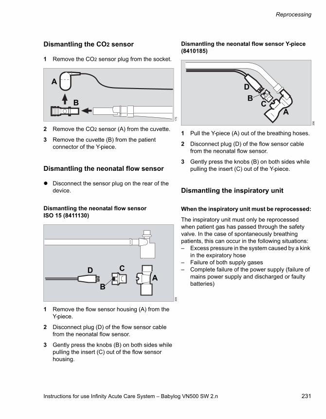
Instructions for use Infinity Acute Care System – Babylog VN500 SW 2.n 231
Reprocessing
Dismantling the CO2 sensor
1 Remove the CO2 sensor plug from the socket.
2 Remove the CO2 sensor (A) from the cuvette.
3 Remove the cuvette (B) from the patient connector of the Y-piece.
Dismantling the neonatal flow sensor
Disconnect the sensor plug on the rear of the device.
Dismantling the neonatal flow sensor ISO 15 (8411130)
1 Remove the flow sensor housing (A) from the Y-piece.
2 Disconnect plug (D) of the flow sensor cable from the neonatal flow sensor.
3 Gently press the knobs (B) on both sides while pulling the insert (C) out of the flow sensor housing.
Dismantling the neonatal flow sensor Y-piece (8410185)
1 Pull the Y-piece (A) out of the breathing hoses.
2 Disconnect plug (D) of the flow sensor cable from the neonatal flow sensor.
3 Gently press the knobs (B) on both sides while pulling the insert (C) out of the Y-piece.
Dismantling the inspiratory unit
When the inspiratory unit must be reprocessed:
The inspiratory unit must only be reprocessed when patient gas has passed through the safety valve. In the case of spontaneously breathing patients, this can occur in the following situations:– Excess pressure in the system caused by a kink
in the expiratory hose– Failure of both supply gases– Complete failure of the power supply (failure of
mains power supply and discharged or faulty batteries)
17
53
09
A
B
D
B
CA
35
6
D
BC
A

Reprocessing
232 Instructions for use Infinity Acute Care System – Babylog VN500 SW 2.n
Removing the inspiratory unit
The inspiratory unit must only be removed when the device is switched off.
1 Press and hold the locking lever (A) on the underside of the inspiratory unit.
2 Simultaneously turn the inspiratory unit (B) approx. 20° counterclockwise.
3 Remove the inspiratory unit from the fitting.
Dismantling the inspiratory unit
1 Remove the diaphragm with adapter (C) from the fitting of the inspiratory unit.
2 Do not dismantle the inspiratory unit any further.
Dismantling the pneumatic medication nebulizer
1 Remove the nebulizer hose (A) from the medication nebulizer (B) and from the nebulizer port on the device.
2 Remove the medication nebulizer (B) from the breathing circuit.
3 Remove the corrugated hose for the breathing circuit (C) from the inlet port.
4 Remove the corrugated hose (D) from the outlet port.
5 Dismantle the medication nebulizer in accordance with the corresponding instructions for use.
Dismantling other accessories
Dismantle the breathing gas humidifier, the Aeroneb nebulizer and the bacterial filter in accordance with the corresponding instructions for use.
03
6_
VN
50
01
97
_V
N5
00
A B
C
04
4_
VN
50
0
AB
C D
Instructions for use Infinity Acute Care System – Babylog VN500 SW 2.n 233
Reprocessing
Information on reprocessing
Instructions for reprocessing are based on internationally accepted guidelines, e.g., standard ISO 17664.
The components through which contaminated breathing gas passes during normal operation and in the event of a fault must be reprocessed. In normal operation breathing gas passes through the expiratory valve or the expiratory valve with ejector and muffler and other accessories in the expiratory path. In the event of a fault, the inspiratory unit and other accessories in the inspiratory path can become contaminated.
Safety information
WARNING
Risk due to inappropriately reprocessed products
Reusable products must be reprocessed, otherwise there is an increased risk of infection and the products may no longer function correctly.– Observe the hygiene regulations and
reprocessing regulations of the healthcare facility.
– Observe national hygiene regulations and reprocessing regulations.
– Use validated procedures for reprocessing.
– Reprocess reusable products after every use.
– Observe the manufacturer's instructions for cleaning agents, disinfectants, and reprocessing devices.
CAUTION
Risk due to faulty products
Signs of wear, e.g., cracks, deformation, discoloration, or peeling, may occur with reprocessed products.
Check the products for signs of wear and replace them if necessary.
CAUTION
Health hazard
Do not sterilize parts in ethylene oxide. Ethylene oxide may diffuse into the parts.
CAUTION
For infectious patients, all parts that come into contact with breathing gas also have to be sterilized after disinfection and cleaning.
Reprocessing
234 Instructions for use Infinity Acute Care System – Babylog VN500 SW 2.n
Safety information on disposable articles
Safety information on the neonatal flow sensor
WARNING
Risk of patient injury as a result of failure of the accessories
Disposable articles were developed, tested and manufactured for single use only. Reuse, reprocessing or sterilization can lead to a failure of the accessories and cause injuries to the patient.
Do not reuse, reprocess, or sterilize disposable articles.
WARNING
Risk of fire
Residual vapors of easily flammable disinfectants (e.g., alcohols) and deposits that were not removed during reprocessing can ignite when the flow sensor is in use.– Ensure particle-free cleaning and
disinfection.– After disinfection, allow the flow sensor to
air for at least 30 minutes.– Before inserting the flow sensor check for
visible damage and soiling, such as residual mucus, medication aerosols, and particles.
– Replace flow sensors when damaged, soiled, or not particle-free.
CAUTION
Risk of failure of flow measurement
Improper reprocessing and soiling, such as deposits or particles, can damage the flow sensor:– No machine cleaning or disinfection of the
sensor insert– No plasma sterilization or radiation
sterilization– No compressed air– No water jets, compressed air, brushes or the
like when cleaning the sensor insert– No ultrasonic bath– Clean and disinfect the flow sensor in
accordance with the corresponding instructions for use.
– For disinfecting the flow sensor use only clean disinfectant solutions.
NOTE
– Do not use brushes for reprocessing the sensor insert and do not use a syringe on the sensor insert.
– For reprocessing the housing use lint-free brushes only.

Instructions for use Infinity Acute Care System – Babylog VN500 SW 2.n 235
Reprocessing
Classifications for reprocessing
Classification of medical devices
Medical devices and their components are classified according to the way they are used and the resulting risk.
Classification of device-specific components
Observe the instructions for use for the components.
The following classification is a recommendation from Dräger.
Non-critical
– Babylog VN500 ventilation unit
– Medical Cockpit display unit
– GS500 gas supply unit
– PS500 power supply unit
– Trolley with accessory mounts
– System cable
– Compressed gas hoses
– CO2 sensor
– Connection cable for the neonatal flow sensor
– Data link cable
Semi-critical A
– Reusable cuvette for the CO2 sensor
– Neonatal flow sensor Y-piece or ISO 15, including individual parts
Semi-critical B
– Infinity ID neonatal expiratory valve, including individual parts
– Inspiratory unit, including individual parts
Classification Definition
Non-critical Components that come only into contact with skin that is intact
Semi-critical (A, B) Components that carry breathing gas or come into contact with mucous membranes or pathologically altered skin
Critical (A, B, C) Components that penetrate skin or mucous membranes or come into contact with blood

Reprocessing
236 Instructions for use Infinity Acute Care System – Babylog VN500 SW 2.n
Reprocessing list
Components Surface disinfec-tion with cleaning
Manual clean-ing followed by disinfec-tion by immersion
Machine cleaning with thermal disin-fection
Steam steril-ization
Special reprocessing measures
Babylog VN500 ventilation unit
Yes No No No No
Medical Cockpitdisplay unit
Yes No No No Do not spray cleaning agent and disinfectant directly on the touch screen.
GS500 gas supply unit
Yes No No No No
PS500 power supply unit
Yes No No No No
Trolley with accessory mounts
Yes No No No No
System cable Yes No No No No
Compressed gas hoses
Yes No No No No
CO2 sensor Yes No No No Avoid residues on the test filter.
Connection cable for the neonatal flow sensor
Yes No No No No
Data link cable Yes No No No No
Reusable cuvette for the CO2 sensor
No Possible Yes Yes Wipe off any contamination, particularly inside and outside the windows, using a soft disposable tissue and cotton swabs, under running water if necessary. Only cleaning agent, and no rinse aid, must be used for automatic cleaning of the cuvette. Otherwise, there is a risk of cracks developing.

Instructions for use Infinity Acute Care System – Babylog VN500 SW 2.n 237
Reprocessing
Neonatal flow sensor Y-piece or ISO 15
No Yes No No See "Neonatal flow sensors" on page 242.
Infinity ID neonatal expiratory valve
No Possible Yes Yes1) See "Infinity ID neonatal expiratory valve" on page 242.
Inspiratory unit No Possible Yes Yes1) Only reprocess the inspiratory unit if breathing gas has passed through the safety valve.
1) For further information on sterilizing, see page 241.
Components Surface disinfec-tion with cleaning
Manual clean-ing followed by disinfec-tion by immersion
Machine cleaning with thermal disin-fection
Steam steril-ization
Special reprocessing measures
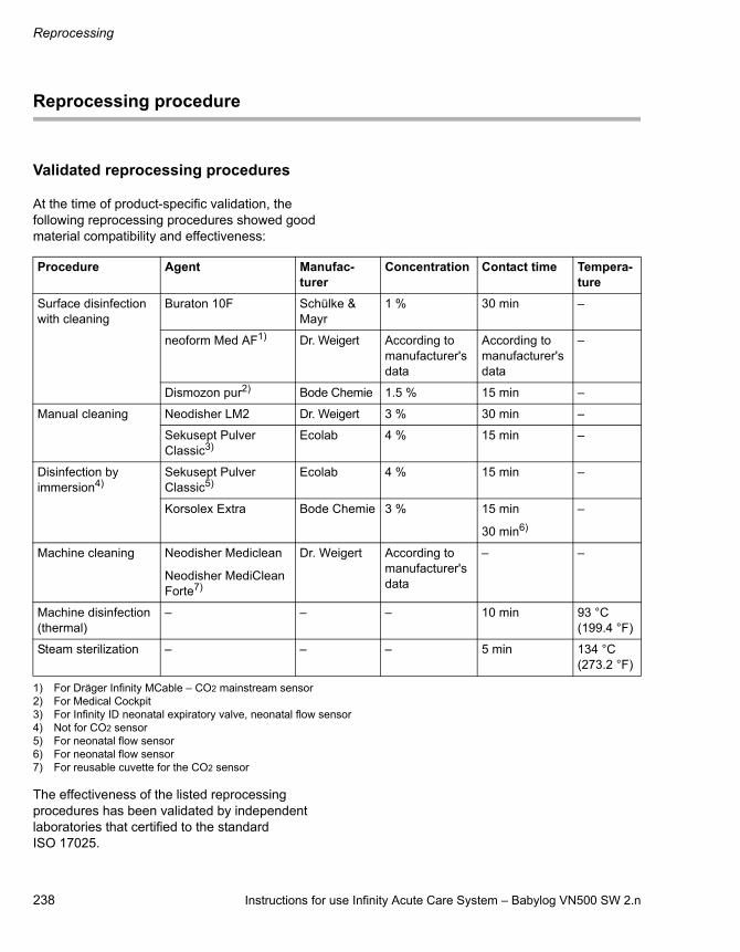
Reprocessing
238 Instructions for use Infinity Acute Care System – Babylog VN500 SW 2.n
Reprocessing procedure
Validated reprocessing procedures
At the time of product-specific validation, the following reprocessing procedures showed good material compatibility and effectiveness:
The effectiveness of the listed reprocessing procedures has been validated by independent laboratories that certified to the standard ISO 17025.
Procedure Agent Manufac-turer
Concentration Contact time Tempera-ture
Surface disinfection with cleaning
Buraton 10F Schülke & Mayr
1 % 30 min –
neoform Med AF1)
1) For Dräger Infinity MCable – CO2 mainstream sensor
Dr. Weigert According to manufacturer's data
According to manufacturer's data
–
Dismozon pur2)
2) For Medical Cockpit
Bode Chemie 1.5 % 15 min –
Manual cleaning Neodisher LM2 Dr. Weigert 3 % 30 min –
Sekusept Pulver Classic3)
3) For Infinity ID neonatal expiratory valve, neonatal flow sensor
Ecolab 4 % 15 min –
Disinfection by immersion4)
4) Not for CO2 sensor
Sekusept Pulver Classic5)
5) For neonatal flow sensor
Ecolab 4 % 15 min –
Korsolex Extra Bode Chemie 3 % 15 min
30 min6)
6) For neonatal flow sensor
–
Machine cleaning Neodisher Mediclean
Neodisher MediClean Forte7)
7) For reusable cuvette for the CO2 sensor
Dr. Weigert According to manufacturer's data
– –
Machine disinfection (thermal)
– – – 10 min 93 °C (199.4 °F)
Steam sterilization – – – 5 min 134 °C (273.2 °F)

Instructions for use Infinity Acute Care System – Babylog VN500 SW 2.n 239
Reprocessing
Disinfectants
Use disinfectants that are nationally approved and are suitable for the particular reprocessing procedure.
Surface disinfectants
At the time of the test, the surface disinfectants listed in the following table showed good material compatibility. They can be used in addition to the surface disinfectants listed in the section "Validated reprocessing procedures".
The manufacturers of the surface disinfectants have verified at least the following spectra of activity:– Bactericidal– Yeasticidal– Virucidal or virucidal against enveloped viruses
Observe the specifications of the surface disinfectant manufacturers.
Other surface disinfectants are used at one's own risk.
Dräger points out that oxygen-releasing agents and chlorine-releasing agents may cause color change in some materials. Color change does not indicate that the product is not functioning correctly.
Class of active ingredient Surface disinfectant Manufacturer
Chlorine-releasing agents Actichlor plus Ecolab
BruTab 6S Brulin
Clorox Professional Disinfecting Bleach Cleaner
Clorox
Dispatch Hospital Cleaner Disinfectant Towels with Bleach
Klorsept 17 Medentech
Oxygen-releasing agents Descogen Liquid Antiseptica
Descogen Liquid r.f.u.
Dismozon plus Bode Chemie
Dismozon pur
Oxycide Ecolab USA
Perform Schülke & Mayr
Virkon DuPont
Quaternary ammonium compounds
Mikrozid sensitive liquid1)
1) Virucidal against enveloped viruses
Schülke & Mayr
Mikrozid sensitive wipes1)
Mikrozid alcohol free liquid1)
Mikrozid alcohol free wipes1)
acryl-des1)
Aldehydes Buraton 10 F Schülke & Mayr

Reprocessing
240 Instructions for use Infinity Acute Care System – Babylog VN500 SW 2.n
Surface disinfection with cleaning
1 Remove soiling immediately. Use a cloth dampened with disinfectant to remove soiling.
2 Perform surface disinfection.
3 After the product has been exposed to the disinfectant for the specified contact time, remove residual disinfectant.
4 Wipe with a cloth dampened with water (preferably drinking-water quality). Allow the product to dry.
5 Check the product for visible soiling. Repeat steps 1 to 5 if necessary.
6 Check the product for visible damage and replace if necessary.
Manual cleaning followed by disinfection by immersion
Manual cleaning
The cleaning agent that is used must have a pH of between 9 and 12.
1 Wash off superficial soiling under running water.
2 Prepare the cleaning solution in accordance with the manufacturer's instructions.
3 Swirl the product backwards and forwards several times in the solution. Make sure that the solution reaches all surfaces and interior spaces.
4 Rinse the product under running water until residual cleaning agent is no longer discernible.
5 Check the product for visible soiling. Repeat steps 1 to 5 if necessary.
6 Check the product for visible damage and replace if necessary.
Disinfection by immersion
1 Prepare the disinfectant solution in accordance with the manufacturer's instructions.
2 Swirl the product backwards and forwards several times in the solution. Make sure that the solution reaches all surfaces and interior spaces.
3 After the contact time has elapsed, rinse the product under running water until residual disinfectant is no longer discernible.
4 Check the product for visible damage and replace if necessary.
5 Thoroughly shake out residual water. Allow the product to dry completely.
WARNING
Risk due to penetrating liquid
Penetrating liquid may cause the following:– Damage to the device– Electric shock– Device malfunction
Ensure that no liquid penetrates the device.

Instructions for use Infinity Acute Care System – Babylog VN500 SW 2.n 241
Reprocessing
Machine cleaning with thermal disinfection
Use a washer-disinfector that meets the requirements of the standard ISO 15883. Dräger recommends the use of a cart for anesthesia accessories and ventilation accessories.
1 Securely position the product in the basket. Ensure the following:– All surfaces and interior spaces can be
flushed completely.– The water can drain off freely.
2 Use a suitable cleaning agent.
3 Select a suitable cycle.
4 Use demineralized water for the final rinsing.
5 After the cycle has ended, check the product for visible soiling. If necessary, repeat the cycle or perform manual cleaning and disinfection by immersion.
6 Check the product for visible damage and replace if necessary.
7 Allow the product to dry completely.
Steam sterilization
Use a steam sterilizer that meets the requirements of the standard ISO 17665. Dräger recommends steam sterilization with fractionated vacuum.
Prerequisite: The product has been cleaned and disinfected.
1 Sterilize the product.
2 Check the product for visible damage and replace if necessary.
Additional information
Sterilization of the expiratory valve or inspiratory valve may gradually impair the operation of RFID transmission. This may mean that Infinity ID breathing circuit functions may not work or may no longer work reliably. If the message Infinity ID breathing circuit detected. is not displayed when an Infinity ID breathing circuit is connected, use a different Infinity ID breathing circuit. If the message is still not displayed, replace the expiratory valve or inspiratory valve.

Reprocessing
242 Instructions for use Infinity Acute Care System – Babylog VN500 SW 2.n
Special reprocessing measures
Infinity ID neonatal expiratory valve
Carry out manual cleaning:
1 Immerse the neonatal expiratory valve in the solution and agitate it slightly so that the air can escape.
2 Before the contact time begins and after it has elapsed, fit a syringe (A) containing 20 mL of solution to the ejector channel (B). Inject and extract the solution several times with the syringe.
Perform manual disinfection in the same manner.
Before assembling the neonatal expiratory valve:
Neonatal flow sensors
Manual cleaning followed by disinfection by immersion must be carried out for complete reprocessing of the flow sensor.
Remove the sensor insert of the neonatal flow sensor from the housing.
Manual cleaning:
The cleaning agent that is used must have a pH of between 9 and 12.
1 Prepare the cleaning agent in accordance with the manufacturer's data in a container with a cover.
2 Place the housing and sensor insert in the solution, ensuring there are no bubbles. Swirl the parts back and forth for approx. 1 minute at the beginning and end of the contact time. Make sure that the solution reaches all surfaces and interior spaces.
3 At the beginning and end of the contact time, spray through each opening in the housing 3 times using a 20 mL syringe (D).
35
2
NOTE
To ensure the functional integrity of the device, check the ejector (A) for visible residues.If soiled, repeat manual cleaning.
37
7_
VN
50
0
AB
A
35
5
NOTE
– Do not use brushes for reprocessing the sensor insert and do not use a syringe on the sensor insert.
– For reprocessing the housing use lint-free brushes only.
A
D
BC
Instructions for use Infinity Acute Care System – Babylog VN500 SW 2.n 243
Reprocessing
4 Clean the housing and the Y-piece (B) with a lint-free brush (A): Insert and remove it vertically ten times in each of the two connection openings of the Y-piece (B) and then, at an angle, insert and remove it ten times in both corners of the opening for the sensor insert (C).
5 Rinse the housing and sensor insert in a water bath (preferably drinking-water quality) until cleaning agent residues are no longer discernible.
Disinfection by immersion:
1 Prepare the disinfectant solution in accordance with the manufacturer's data in a container with a cover.
2 Place the housing and sensor insert in the solution, ensuring there are no bubbles. Swirl the parts back and forth for approx. 1 minute at the beginning and end of the contact time. Make sure that the solution reaches all surfaces and interior spaces.
3 At the beginning and end of the contact time, spray through each opening in the housing 3 times using a 20 mL syringe (D).
4 Clean the housing and the Y-piece (B) with a lint-free brush (A): Insert and remove it vertically ten times in each of the two connection openings of the Y-piece (B) and then, at an angle, insert and remove it ten times in both corners of the opening for the sensor insert (C).
5 Rinse the housing and sensor insert in a water bath (preferably drinking-water quality) until disinfectant residues are no longer discernible.
6 Check parts for visible soiling or damage. Check the sensor insert for damage to the measuring wires and their pegs.
7 Thoroughly shake out residual water. Allow the parts to dry completely.
Machine cleaning with thermal disinfection:
Sterilization:
Only sterilize the flow sensor when it is assembled.
CAUTION
Only carry out machine cleaning and disinfection on the housing.
CAUTION
Risk of patient injury due to failure of the flow measurement
Improper sterilization may damage the flow sensor. Only use the specified sterilization procedures.

Reprocessing
244 Instructions for use Infinity Acute Care System – Babylog VN500 SW 2.n
After reprocessing
Assembling the components
Assembling expiratory valve
1 Make sure all parts of the expiratory valve are completely dry, otherwise this may impair proper functioning.
2 Fit the muffler (B) to the expiratory valve.
3 Fit the diaphragm (A) onto the edge of the expiratory valve housing.
4 Fit the water trap container (C).
Inserting the expiratory valve into Babylog VN500
Prerequisite: The flap on the front is pivoted upwards.
1 Turn the locking ring (D) as far as possible to the left.
2 Push the expiratory valve into the fitting.
3 Turn the locking ring (D) as far as it will go to the right until it clicks audibly into place.
4 Check that it is properly secured by gently pulling on the expiratory valve.
5 Close the flap.
Further information on the expiratory valve:The expiratory valve can be reused as long as the test point in the device check is passed. Exchange the expiratory valve if signs of wear become visible, such as cracks in the plastic parts, deformation and hardening of the rubber parts. Discolorations of the metal insert do not impair its function.
07
2_
VN
50
00
40
_V
N5
00
A
B
C
07
3_
VN
50
0
D
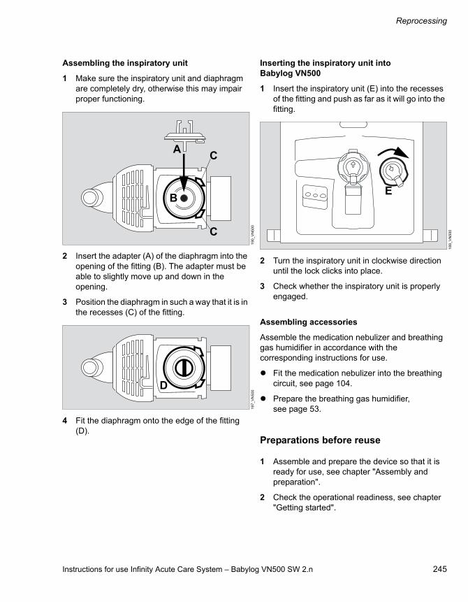
Instructions for use Infinity Acute Care System – Babylog VN500 SW 2.n 245
Reprocessing
Assembling the inspiratory unit
1 Make sure the inspiratory unit and diaphragm are completely dry, otherwise this may impair proper functioning.
2 Insert the adapter (A) of the diaphragm into the opening of the fitting (B). The adapter must be able to slightly move up and down in the opening.
3 Position the diaphragm in such a way that it is in the recesses (C) of the fitting.
4 Fit the diaphragm onto the edge of the fitting (D).
Inserting the inspiratory unit into Babylog VN500
1 Insert the inspiratory unit (E) into the recesses of the fitting and push as far as it will go into the fitting.
2 Turn the inspiratory unit in clockwise direction until the lock clicks into place.
3 Check whether the inspiratory unit is properly engaged.
Assembling accessories
Assemble the medication nebulizer and breathing gas humidifier in accordance with the corresponding instructions for use.
Fit the medication nebulizer into the breathing circuit, see page 104.
Prepare the breathing gas humidifier, see page 53.
Preparations before reuse
1 Assemble and prepare the device so that it is ready for use, see chapter "Assembly and preparation".
2 Check the operational readiness, see chapter "Getting started".
19
0_
VN
50
01
97
_V
N5
00
A
B
C
C
D
18
9_
VN
50
0
E

246 Instructions for use Infinity Acute Care System – Babylog VN500 SW 2.n
This page has been left blank intentionally.

Instructions for use Infinity Acute Care System – Babylog VN500 SW 2.n 247
Maintenance
Maintenance
Overview . . . . . . . . . . . . . . . . . . . . . . . . . . . . . 248
Definition of maintenance concepts . . . . . . . . . 248
Inspection . . . . . . . . . . . . . . . . . . . . . . . . . . . . 248
Safety checks . . . . . . . . . . . . . . . . . . . . . . . . . . 249Remote Service . . . . . . . . . . . . . . . . . . . . . . . . 249
Preventive maintenance . . . . . . . . . . . . . . . . 250
Repair . . . . . . . . . . . . . . . . . . . . . . . . . . . . . . . 250
Replacing the ambient air filter . . . . . . . . . . . 251
Replacing the diaphragm of the expiratory valve . . . . . . . . . . . . . . . . . . . . . . . 251
Replacing the expiratory valve . . . . . . . . . . . 252
Preventive maintenance on the GS500 gas supply unit . . . . . . . . . . . . . . . . . . . . . . . . 252
Replacing the breathing gas filter in the blower unit . . . . . . . . . . . . . . . . . . . . . . . . . . . . 252Replacing the filter mat. . . . . . . . . . . . . . . . . . . 253
Battery maintenance . . . . . . . . . . . . . . . . . . . 254
Information on battery maintenance. . . . . . . . . 254Battery check . . . . . . . . . . . . . . . . . . . . . . . . . . 254Battery check page. . . . . . . . . . . . . . . . . . . . . . 256

Maintenance
248 Instructions for use Infinity Acute Care System – Babylog VN500 SW 2.n
Overview
This chapter describes all maintenance steps necessary to maintain the proper functioning of the device. These measures must be performed by the personnel responsible.
Only perform maintenance work when no patient is connected to the device.
Definition of maintenance concepts
Inspection
Inspections must be carried out regularly according to the following specifications and in the specified intervals..
CAUTION
Disinfect and clean device or device parts before any maintenance measures and also before returning the medical device for repair.
WARNING
Risk of electric shock
Current-carrying components are located under the cover. Do not remove the cover. Maintenance work must be performed by service personnel or by experts. Dräger recommends that DrägerService performs these tasks.
Concept Definition
Maintenance Appropriate measures intended to retain the specified condition of a medical device
Inspection Measures intended to determine and assess the actual state of a medical device
Preventive maintenance
Repeated indicated measures intended to retain the specified condition of a medical device
Repair Measures intended to restore the functional condition of a medical device after the failure of a device function
Checks Interval Personnel responsible
Inspection and safety checks1)
1) Designation applies to the Federal Republic of Germany; corresponds to the “Recurring safety inspection” in the Republic of Austria
Every 12 months Service personnel

Instructions for use Infinity Acute Care System – Babylog VN500 SW 2.n 249
Maintenance
Safety checks
The safety checks are no substitute for the preventive maintenance measures (including preventive replacement of wear parts) indicated by the manufacturer.
1 Check accompanying documents:– Instructions for use are available.
2 Perform a functional test of the following features:– Perform a device check and a breathing
circuit check according to the instructions for use.
– Perform a functional test of the airway pressure measurement.
– Perform a functional test of the flow measurement.
– Perform a functional test of the batteries (Babylog VN500 or PS500).
3 Verify that the device combination is in good condition:– Labels complete and legible.– No visible damage.– Fuses which are accessible from the
outside are in compliance with the specified values.
4 Check that the equipment of the medical device is complete according to the instructions for use.
5 Check the electrical safety according to IEC 62353.
6 Check safety features:– Correct functioning of the emergency
expiratory valve: Pressure rise 1.9 to 4.4 mbar (1.9 to 4.4 cmH2O) at a flow of 4.5 to 5.5 L/min.
– Correct functioning of the non-return valve in the expiratory valve.
– Correct functioning of the emergency breathing valve: Maximum pressure drop of 6.5 mbar (6.5 cmH2O) at a suction flow of 60 to 65 L/min.
– Correct functioning of the alarm generator– Correct functioning of the non-return valves
in the gas inlet for O2 and Air
Remote Service
From software release SW 2.20, Babylog VN500 supports the following Remote Service functionalities:– Help Ticket– Remote Device Check
Contact the responsible DrägerService representative for further information on the Remote Service function.
CAUTION
Perform safety checks at the indicated intervals. Otherwise, the correct functioning of the medical device can be impaired.

Maintenance
250 Instructions for use Infinity Acute Care System – Babylog VN500 SW 2.n
Preventive maintenance
Maintenance intervals
Repair
Dräger recommends that all repairs are carried out by DrägerService and that only original Dräger parts are used.
WARNING
Risk due to defective components
Device failure is possible due to wear or material fatigue of the components. To maintain the function of all components, this device must be inspected and serviced at the intervals specified by the manufacturer.
Component Interval Measure Personnel responsible
Ambient air filter Every 4 weeks Cleaning, replace if necessary, see page 251
User
Every 12 months Replace, see page 251 User
Diaphragm of the expiratory valve
Every 12 months Replace, see page 251 User
Expiratory valve Every 2 years Replace, see page 252 User
GS500: Breathing gas filter in the blower unit
Every 12 months Replace, see page 254 Service personnel
GS500: Filter mat Every 12 months Replace, see page 253 Service personnel
Batteries Every 3 months Check capacity, see page 254 Service personnel
Replace if necessary Experts
Every 2 years Replace Experts
Air filter (in the Air gas inlet)
Every 2 years Replace Experts
O2 filter (in the O2 gas inlet)
Every 6 years Replace Experts

Instructions for use Infinity Acute Care System – Babylog VN500 SW 2.n 251
Maintenance
Replacing the ambient air filter
Visually inspect the ambient air filter for contamination after 4 weeks; clean or replace if necessary. Replace after 12 months at the latest.
1 Unscrew the screw (A) on the cover of the ambient air filter.
2 Open the cover (B).
3 Remove the filter from the mount.
4 Fit a new filter or clean the old filter in warm soapy water and dry thoroughly.
5 Insert the filter into the mount without creasing.
6 Close the cover (B) and retighten the screw (A).
7 Dispose of used filter with domestic waste.
Replacing the diaphragm of the expiratory valve
Prerequisite: The expiratory valve has been removed, see "Removing the expiratory valve" on page 230.
1 Remove the diaphragm (A).
2 Fit the new diaphragm onto the edge of the expiratory valve housing. Make sure that the diaphragm is fitted properly.
3 Dispose of used diaphragm with domestic waste.
4 Fit the expiratory valve, see "Inserting the expiratory valve into the ventilation unit" on page 51.
CAUTION
Replace the ambient air filter at regular intervals. Otherwise operation of the device may be impaired.
03
5_
VN
50
0
BA
18
7_
VN
50
0
A

Maintenance
252 Instructions for use Infinity Acute Care System – Babylog VN500 SW 2.n
Replacing the expiratory valve
1 Remove the expiratory valve, see page 230. Dispose of the expiratory valve in accordance with local waste disposal regulations.
2 Fit the expiratory valve, see page 244.
3 Insert the expiratory valve into the ventilation unit, see page 244.
Preventive maintenance on the GS500 gas supply unit
Replacing the breathing gas filter in the blower unit
The breathing gas filter is located behind the left-hand side panel of the GS500 gas supply unit.
1 Loosen the screws on the rear of the device sufficiently for the side panel to be removed. Remove the side panel.Ensure that the filter fleece attached to the side section is not loosened.
2 Take hold of the breathing gas filter by the handle and withdraw it from the GS500 gas supply unit. Dispose of the used breathing gas filter in accordance with local waste disposal regulations.
3 Insert the new breathing gas filter into the GS500 gas supply unit as far as it will go.
4 Fit the side panel and tighten the screws.
37
0
A
C
B

Instructions for use Infinity Acute Care System – Babylog VN500 SW 2.n 253
Maintenance
Replacing the filter mat
The filter mat is fastened to the inside of the left-hand side panel of the GS500 gas supply unit.
1 Loosen the screws on the rear of the device sufficiently for the side panel to be removed. Remove the side panel.
2 Remove the filter mat and dispose of it in accordance with local waste disposal regulations.
3 Fit the new filter mat with its side to the boundary. Carefully press the filter mat on to the pointed retaining elements. Check that the filter mat is secured.
4 Fit the side panel and tighten the screws.
37
1
A
B
C
Maintenance
254 Instructions for use Infinity Acute Care System – Babylog VN500 SW 2.n
Battery maintenance
Information on battery maintenance
The following actions are required to achieve the maximum life span of the batteries:
Always fully charge the batteries.
Connect the device to the mains power supply at the latest after 5 days to charge the batteries. Observe the required charging time.
If recharging is not possible after 5 days at the latest, do the following:
Set the toggle switch to the position and then disconnect the power plug.
The device is then in the energy-saving mode and the discharge is reduced to the self-discharge of the batteries. Check that the capacity of the batteries is sufficient before use on a patient. The batteries may be exhausted or faulty as a result of excessively long storage.
Batteries are wear parts. The replacement intervals depend on the utilization. Observe the test intervals.
Storage at an increased ambient temperature reduces the life span of the batteries. The storage duration must not be exceeded. See chapter "Ambient conditions" on page 262.
The capacity of the batteries used must be checked regularly.
The batteries must have sufficient capacity. Replace the batteries if necessary.
Battery check
A battery check is required at regular intervals to determine the current state of the batteries. The battery check determines the approximate operating time.
The battery check consists of a charge-discharge-charge cycle. After the batteries have been fully charged, the device is operated in test mode with power supply from the batteries. The determined operating time is the approximate operating time to be expected in the next period of battery operation with typical ventilation without GS500.
Dräger recommends the following test intervals:
Prerequisites for the battery check
– The device is connected to the central gas supply.
– The device is connected to the mains power supply.
– The device is prepared and ready for use.– The test lung is connected.– A ventilation pattern is set, e.g.:
– PC-AC– FiO2 = 21 %– RR = 60/min– Pinsp = 20 mbar (or hPa or cmH2O)– PEEP = 5 mbar (or hPa or cmH2O)
Internal battery (NiMH) Every 3 months
PS500 power supply unit (VRLA)
Every 3 months
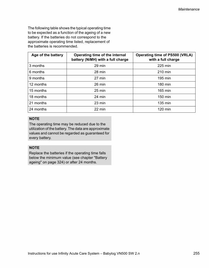
Instructions for use Infinity Acute Care System – Babylog VN500 SW 2.n 255
Maintenance
The following table shows the typical operating time to be expected as a function of the ageing of a new battery. If the batteries do not correspond to the approximate operating time listed, replacement of the batteries is recommended.
Age of the battery Operating time of the internal battery (NiMH) with a full charge
Operating time of PS500 (VRLA) with a full charge
3 months 29 min 225 min
6 months 28 min 210 min
9 months 27 min 195 min
12 months 26 min 180 min
15 months 25 min 165 min
18 months 24 min 150 min
21 months 23 min 135 min
24 months 22 min 120 min
NOTE
The operating time may be reduced due to the utilization of the battery. The data are approximate values and cannot be regarded as guaranteed for every battery.
NOTE
Replace the batteries if the operating time falls below the minimum value (see chapter "Battery ageing" on page 324) or after 24 months.

Maintenance
256 Instructions for use Infinity Acute Care System – Babylog VN500 SW 2.n
Battery check page
Prerequisite: The Start/Standby > System check dialog (A) window is opened.
1 Touch the Battery check tab (B).
The Battery check page contains the following:– Battery check complete (C)– Battery check PS500 (D)– Battery check internal battery (E)
Information displayed in the (I) field for each battery:
– Date of the last battery check– Determined operating time (value
determined in the battery check during typical ventilation without GS500). See chapter "Battery check" on page 254.
– Next battery check due in xx days– Battery replacement in xx months– Current operating time
This value is indicated to the nearest 5 or 10 minutes depending on the battery used and based on the present power consumption of the device.
Starting the battery check
The battery check can only be started if the device is connected to the mains power supply.
Touch the Start button (F) and confirm. The appropriate battery check will be started. The result of the battery check is displayed after completion.
The duration of the battery check is decremented in hours and displayed in field (H).
If a battery check fails, the device will cancel the check. The canceled check is shown as a colorless dot.
Canceling the battery check
Touch the Cancel button (G) and confirm. The appropriate battery check will be canceled. The canceled check is shown as a colorless dot.3
72
Start/Standby
A
B
C
D
E
F
F
F
G
G
G
H
H
H
I
I
Instructions for use Infinity Acute Care System – Babylog VN500 SW 2.n 257
Disposal
Disposal
Safety information on disposal . . . . . . . . . . . 258
Disposal of packaging material. . . . . . . . . . . 258
Disposal of batteries . . . . . . . . . . . . . . . . . . . 259
Disposal of neonatal flow sensor . . . . . . . . . 259
Disposal of medical devices . . . . . . . . . . . . . 259

Disposal
258 Instructions for use Infinity Acute Care System – Babylog VN500 SW 2.n
Safety information on disposal
For countries subject to EU Directive 2002/96/EC
This device is subject to EU Directive 2002/96/EC (WEEE). In order to comply with its registration according to this directive, this device may not be disposed of at municipal collection points for waste electrical equipment. Dräger has authorized a company to collect and dispose of this device. To initiate collection or for further information, visit Dräger on the Internet at www.draeger.com. Use the Search function with the keyword "WEEE" to find the relevant information. If access to Dräger's website is not possible, contact the local Dräger Organization.
Disposal of packaging material
Dispose of the packaging material of the device and the accessories listed in the list of accessories in accordance with the applicable laws and regulations.
CAUTION
The device and its components must be disinfected and cleaned before disposal!

Instructions for use Infinity Acute Care System – Babylog VN500 SW 2.n 259
Disposal
Disposal of batteries
The medical device contains batteries with toxic substances.In the Federal Republic of Germany: The user is obliged by the ordinance on the return and disposal of used batteries to return batteries which contain toxic substances either to the manufacturer/sales outlet or to a collection center operated by public waste disposal corporations. The battery installed in the device must therefore be removed by experts before the device can be disposed of. Observe the applicable laws and regulations for battery disposal.
Disposal of neonatal flow sensor
The flow sensor must be disposed of as infectious waste. Low-emission combustion at over 800 °C (1472 °F).
Disposal of medical devices
At the end of its service life:
Consult the relevant waste disposal company for appropriate disposal.
Observe the applicable laws and regulations.

260 Instructions for use Infinity Acute Care System – Babylog VN500 SW 2.n
This page has been left blank intentionally.

Instructions for use Infinity Acute Care System – Babylog VN500 SW 2.n 261
Technical data
Technical data
Ambient conditions . . . . . . . . . . . . . . . . . . . . 262
Set values . . . . . . . . . . . . . . . . . . . . . . . . . . . . 263
Performance characteristics . . . . . . . . . . . . . 266
Displayed measured values . . . . . . . . . . . . . 269
Displayed calculated values . . . . . . . . . . . . . 272
Monitoring . . . . . . . . . . . . . . . . . . . . . . . . . . . . 273
Operating data . . . . . . . . . . . . . . . . . . . . . . . . 276
Device ports . . . . . . . . . . . . . . . . . . . . . . . . . . 280
Automatic alarm limits . . . . . . . . . . . . . . . . . . 282
Essential performance characteristics. . . . . 285
Connections to IT networks . . . . . . . . . . . . . 286
Information on connecting to the network. . . . . 286
Open-source software . . . . . . . . . . . . . . . . . . 287

Technical data
262 Instructions for use Infinity Acute Care System – Babylog VN500 SW 2.n
Ambient conditions
During operation
Temperature 10 to 40 °C (50 to 104 °F)
Pressure range 700 to 1060 hPa
Altitude up to 3000 m (9842 ft)
Relative humidity 10 to 90 %, without condensation
During storage and transportation
Pressure range 500 to 1060 hPa
Relative humidity 5 to 95 %, non-condensing
Temperature
The technical specifications of the battery manufacturer regarding storage duration refer to a relative humidity of 45 to 85 %. Storage outside this range is possible. In this case, perform a battery test before using the device. Charging every 6 months at the latest is recommended. Several charge and discharge cycles may be required as a battery test in order to completely reactivate the electrochemical composition after long term storage.
Device without PS500 batteries for charging subsequent to storage
For storage up to 6 months –20 to <45 °C (–4 to <113 °F)
For storage up to 1 month –20 to <55 °C (–4 to <131 °F)
For storage up to 1 week –20 to 60 °C (–4 to 140 °F)
Device with PS500 batteries for charging subsequent to storage
For storage up to 6 months –15 to 25 °C (5 to 77 °F)
For storage up to 3 months –15 to 40 °C (5 to 104 °F)
Depending on the accessories used, more stringent ambient conditions can apply. Observe corresponding instructions for use.

Instructions for use Infinity Acute Care System – Babylog VN500 SW 2.n 263
Technical data
Set values
The required parameters can be adjusted with the therapy controls of Babylog VN500 without any loss of accuracy. The controlled parameters pressure, flow, volume, and O2 concentration can only be applied with the accuracy of the associated measured values.
The accuracies indicated apply only under the following conditions:– The device is ready for operation, see chapter
"Getting started".– Any accessories being used are approved for
the device, see the list of accessories.– The type of humidification is selected correctly
in the Start/Standby > Br. circuit/ Humidifier dialog window.
The tolerances do not include the measurement uncertainty of external test equipment. This information is available on request.
Respiratory rate RR 0.5 to 150/min
Inspiratory time Ti 0.1 to 3 s
Maximum inspiratory time for flow cycled breaths Timax
Pediatric patients 0.1 to 4 s
Neonates 0.1 to 1.5 s
Tidal volume VT
Pediatric patients 20 to 300 mL
Neonates 2 to 100 mL
Tidal volume for pressure support VT
Pediatric patients 20 to 300 mL
Neonates 2 to 100 mL
Upper limit of tidal volume for PPS VTmax
Pediatric patients 20 to 300 mL
Neonates 2 to 100 mL
Activation state of Apnea Ventilation on, off
Status of the Automatic return from Apnea Ventilation function
on, off

Technical data
264 Instructions for use Infinity Acute Care System – Babylog VN500 SW 2.n
Tidal volume during Apnea Ventilation VTapn
Pediatric patients 20 to 300 mL
Neonates 2 to 100 mL
Respiratory rate during apnea ventilation RRapn 2 to 150/min
Inspiratory flow Flow
Pediatric patients 2 to 30 L/min
Neonates 2 to 30 L/min
Maximum inspiratory flow in NIV mode for neonates Flow max
0 to 30 L/min
Inspiratory pressure Pinsp 1 to 80 mbar (or hPa or cmH2O)
Inspiratory pressure limit Pmax 2 to 100 mbar (or hPa or cmH2O)
O2 concentration FiO2 21 to 100 Vol%
T0...90 test conditions in accordance with ISO 80601-2-12:2011, Sec. 201.12.1.104
Time until the adjusted O2 value reaches the patient connection
taking account of the airway-conducting accessories with the greatest internal volume; with flow monitoring switched on
Pediatric patients and neonates <20 s
Positive end-expiratory pressure PEEP 0 to 35 mbar (or hPa or cmH2O)
Trigger sensitivity Flow trigger 0.2 to 5 L/min
Pressure support Psupp 0 to 80 mbar (or hPa or cmH2O)
Rise time for pressure support Slope
Pediatric patients 0 to 2 s
Neonates 0 to 1.5 s
Airway Pressure Release Ventilation APRV
Inspiratory time Thigh 0.1 to 30 s
Expiratory time Tlow 0.05 to 30 s
Maximum time of low pressure level in APRV/PEF Tlow max
0.05 to 30 s
Inspiratory pressure Phigh 1 to 80 mbar (or hPa or cmH2O)
Expiratory pressure Plow 0 to 35 mbar (or hPa or cmH2O)
Termination criterion (peak expiratory flow) Exp. term.
1 to 80 %PEF
Set values (cont.)

Instructions for use Infinity Acute Care System – Babylog VN500 SW 2.n 265
Technical data
Automatic Tube Compensation ATC
Inner diameter of the tube Tube Ø
Endotracheal tube ET
Pediatric patients 2 to 8 mm (0.08 to 0.31 in)
Neonates 2 to 5 mm (0.08 to 0.2 in)
Tracheostomy tube Trach.
Pediatric patients 2.5 to 8 mm (0.1 to 0.31 in)
Degree of tube compensation Compens. 0 to 100 %
Status of ATC during mandatory inspiration Inspiratory compensation
on/off
Status of ATC during expiratory phase Expiratory compensation
on/off
Proportional Pressure Support PPS
Flow Assist Flow Assist
Pediatric patients 0 to 100 mbar/L/s (or hPa/L/s or cmH2O/L/s)
Neonates 0 to 300 mbar/L/s (or hPa/L/s or cmH2O/L/s)
Volume Assist Flow Assist
Pediatric patients 0 to 1000 mbar/L (or hPa/L or cmH2O/L)
corresponds to compliance compensation 10000 to 1 mL/mbar (or mL/hPa or mL/cmH2O)
Neonates 0 to 4000 mbar/L (or hPa/L or cmH2O/L)
corresponds to compliance compensation 1000 to 0.3 mL/mbar (or mL/hPa or mL/cmH2O)
O2 Therapy
Continuous Flow Flow (BTPS) 2 to 50 L/min
O2 concentration FiO2 21 to 100 Vol%
High Frequency Oscillation HFO
Mean airway pressure during HFO MAPhf 5 to 50 mbar (or hPa or cmH2O)
Frequency of oscillation in HFO fhf 5 to 20 Hz
I to E in HFO I:Ehf 1:1 to 1:3
Pressure amplitude in HFO Ampl hf 5 to 90 mbar (or hPa or cmH2O)
Maximum pressure amplitude in HFO (VG) Ampl hf max
5 to 90 mbar (or hPa or cmH2O)
Tidal volume in HFO VThf 0.2 to 40 mL
Sigh pressure in HFO Psigh 6 to 80 mbar (or hPa or cmH2O)
Respiratory rate of sigh in HFO RRsigh 0 to 30/min
Set values (cont.)

Technical data
266 Instructions for use Infinity Acute Care System – Babylog VN500 SW 2.n
Sigh pressure rise time Slopesigh
Pediatric patients 0 to 2 s
Neonates 0 to 1.5 s
Sigh inspiratory time in HFO Tisigh
0.1 to 3 s
Leakage compensation on/offon: full compensation activeoff: only trigger compensation active
Maneuver settings
Sigh pressure intPEEP 0 to 20 mbar (or hPa or cmH2O)
Time interval between sighs Interval sigh 20 s to 180 min
Number of cycles for a sigh Cycles sigh 1 to 20 exhalations
Oxygen enrichment for suction maneuver
Factor for neonates 1 to 2
Factor for pediatric patients 1 to 2
Performance characteristics
Control principle time-cycled, volume-constant, pressure-controlled
Intermittent PEEP duration 1 to 20 expiratory cycles
Medication nebulization For 5, 10, 15, 30 minutes, continuously ()
Endotracheal suction
Disconnection detection automatic
Reconnection detection automatic
Initial oxygen enrichment max. 3 minutes
Active suction phase max. 2 minutes
Final oxygen enrichment max. 2 minutes
Set values (cont.)

Instructions for use Infinity Acute Care System – Babylog VN500 SW 2.n 267
Technical data
Supply system for spontaneous breathing and Psupp
adaptive CPAP system with high initial flow
Inspiratory flow (BTPS) for pediatric patients (if proximal flow measurement is used, the measuring range is restricted, see section on displayed flow values, page 270)
max. 60 L/min
Inspiratory flow (BTPS) for neonates max. 30 L/min
Base flow, neonates 6 L/min
Base flow, pediatric patients 3 L/min
Base flow, pediatric patients, with active pneumatic nebulization
6 L/min
Supply system for HFO
Inspiratory flow (BTPS) max. 120 L/min
Base flow 25 L/min
Minimum short-term negative pressure during HFO
–40 mbar (or hPa or cmH2O)
In a combination of proximal flow sensor with filters, HME, Ergostar and CO2 cuvette, the airway resistance of the system can be more than 6 mbar (or hPa or cmH2O) if there is a failure of the device and a flow of 15 L/min.
Inspiratory resistance on device failure
Pediatric patients, maximum value <6 mbar at 15 L/min<6 hPa at 15 L/min<6 cmH2O at 15 L/min
Neonates, maximum value <1.5 mbar at 2.5 L/min<1.5 hPa at 2.5 L/min<1.5 cmH2O at 2.5 L/min
Expiratory resistance on device failure
Pediatric patients, maximum value <6.0 mbar at 15 L/min<6.0 hPa at 15 L/min<6.0 cmH2O at 15 L/min
Neonates, maximum value <1.0 mbar at 2.5 L/min<1.0 hPa at 2.5 L/min<1.0 cmH2O at 2.5 L/min
Performance characteristics (cont.)
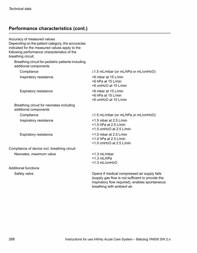
Technical data
268 Instructions for use Infinity Acute Care System – Babylog VN500 SW 2.n
Accuracy of measured valuesDepending on the patient category, the accuracies indicated for the measured values apply to the following performance characteristics of the breathing circuit.
Breathing circuit for pediatric patients including additional components
Compliance 1.5 mL/mbar (or mL/hPa or mL/cmH2O)
Inspiratory resistance <6 mbar at 15 L/min<6 hPa at 15 L/min<6 cmH2O at 15 L/min
Expiratory resistance <6 mbar at 15 L/min<6 hPa at 15 L/min<6 cmH2O at 15 L/min
Breathing circuit for neonates including additional components
Compliance 1.5 mL/mbar (or mL/hPa or mL/cmH2O)
Inspiratory resistance <1.5 mbar at 2.5 L/min<1.5 hPa at 2.5 L/min<1.5 cmH2O at 2.5 L/min
Expiratory resistance <1.0 mbar at 2.5 L/min<1.0 hPa at 2.5 L/min<1.0 cmH2O at 2.5 L/min
Compliance of device incl. breathing circuit
Neonates, maximum value <1.3 mL/mbar<1.3 mL/hPa<1.3 mL/cmH2O
Additional functions
Safety valve Opens if medical compressed air supply fails (supply gas flow is not sufficient to provide the inspiratory flow required), enables spontaneous breathing with ambient air.
Performance characteristics (cont.)
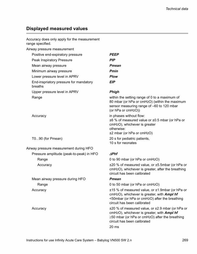
Instructions for use Infinity Acute Care System – Babylog VN500 SW 2.n 269
Technical data
Displayed measured values
Accuracy does only apply for the measurement range specified.
Airway pressure measurement
Positive end-expiratory pressure PEEP
Peak Inspiratory Pressure PIP
Mean airway pressure Pmean
Minimum airway pressure Pmin
Lower pressure level in APRV Plow
End-inspriatory pressure for mandatory breaths
EIP
Upper pressure level in APRV Phigh
Range within the setting range of 0 to a maximum of 80 mbar (or hPa or cmH2O) (within the maximum sensor measuring range of –60 to 120 mbar (or hPa or cmH2O))
Accuracy in phases without flow: ±6 % of measured value or ±0.5 mbar (or hPa or cmH2O), whichever is greaterotherwise:±2 mbar (or hPa or cmH2O)
T0...90 (for Pmean) 20 s for pediatric patients, 10 s for neonates
Airway pressure measurement during HFO
Pressure amplitude (peak-to-peak) in HFO Phf
Range 0 to 90 mbar (or hPa or cmH2O)
Accuracy ±20 % of measured value, or ±5.5mbar (or hPa or cmH2O), whichever is greater, after the breathing circuit has been calibrated
Mean airway pressure during HFO Pmean
Range 0 to 50 mbar (or hPa or cmH2O)
Accuracy ±15 % of measured value, or ±1.9mbar (or hPa or cmH2O), whichever is greater, with Ampl hf <50mbar (or hPa or cmH2O) after the breathing circuit has been calibrated
Accuracy ±20 % of measured value, or ±2.9 mbar (or hPa or cmH2O), whichever is greater, with Ampl hf50 mbar (or hPa or cmH2O) after the breathing circuit has been calibrated
20 ms
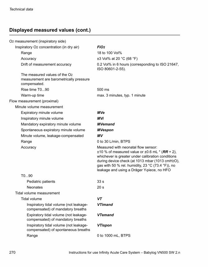
Technical data
270 Instructions for use Infinity Acute Care System – Babylog VN500 SW 2.n
O2 measurement (inspiratory side)
Inspiratory O2 concentration (in dry air) FiO2
Range 18 to 100 Vol%
Accuracy ±3 Vol% at 20 °C (68 °F)
Drift of measurement accuracy 0.2 Vol% in 6 hours (corresponding to ISO 21647, ISO 80601-2-55).
The measured values of the O2 measurement are barometrically pressure compensated.
Rise time T0...90 500 ms
Warm-up time max. 3 minutes, typ. 1 minute
Flow measurement (proximal)
Minute volume measurement
Expiratory minute volume MVe
Inspiratory minute volume MVi
Mandatory expiratory minute volume MVemand
Spontaneous expiratory minute volume MVespon
Minute volume, leakage-compensated MV
Range 0 to 30 L/min, BTPS
Accuracy Measured with neonatal flow sensor:±10 % of measured value or ±0.6 mL * (RR + 2), whichever is greater under calibration conditions during device check (at 1013 mbar (1013 cmH2O), gas with 50 % rel. humidity, 23 °C (73.4 °F)), no leakage and using a Dräger Y-piece, no HFO
T0...90
Pediatric patients 33 s
Neonates 20 s
Tidal volume measurement
Tidal volume VT
Inspiratory tidal volume (not leakage-compensated) of mandatory breaths
VTimand
Expiratory tidal volume (not leakage-compensated) of mandatory breaths
VTemand
Inspiratory tidal volume (not leakage-compensated) of spontaneous breaths
VTispon
Range 0 to 1000 mL, BTPS
Displayed measured values (cont.)

Instructions for use Infinity Acute Care System – Babylog VN500 SW 2.n 271
Technical data
Accuracy Measured with neonatal flow sensor:±10 % of measured value or ±0.6 mL, whichever is greater, under calibration conditions during device check (at 1013 mbar (1013 cmH2O), gas with 50 % rel. humidity, 23 °C (73.4 °F)), no leakage and using a Dräger Y-piece, no HFO
Device Flow (inspiratory, only with HFO)
Range 20 to 40 L/min, BTPS
Accuracy ±10 %
Respiratory rate measurement
Respiratory rate RR
Mandatory respiratory rate RRmand
Portion of mandatory triggered breaths RRtrig
Spontaneous respiratory rate RRspon
Range 0 to 300/min
Accuracy ±1/min for respiratory rates 2/min and±2/min for respiratory rates <2/min
T0...90 33 s
Effective inspiratory time during spontaneous breathing Tispon
0 to 20 s
Effective expiratory time, only if additional setting AutoRelease is active Tlow
0 to 20 s
Inspiratory time to expiratory time ratio for mandatory ventilation I:E
1:300 to 600:1
Inspiratory time to expiratory time ratio for spontaneous breathing I:Espon
1:300 to 600:1
CO2 measurement in mainstream
End-expiratory CO2 concentration etCO2
Range 0 to 100 mmHg or 0 to 13.2 Vol% (at 1013 mbar (1013 cmH2O)) or 0 to 13.3 kPa
Accuracy ±2.0 mmHg in the range 0 to 40 mmHg, ±5 % of the measured value in the range 41 to 100 mmHg±0.27 kPa in the range 0 to 5.33 kPa, ±5 % of the measured value in the range 5.34 to 13.3 kPa±0.26 Vol% in the range 0 to 5.26 Vol%, ±5 % of the measured value in the range 5.27 to 13.2 Vol%
Displayed measured values (cont.)

Technical data
272 Instructions for use Infinity Acute Care System – Babylog VN500 SW 2.n
Measurement conditions Respiratory rate (pediatric patients): 40 to 100/minInspiratory time: >250 msExpiratory time: >250 ms
Drift of measurement accuracy <0.03 Vol% (at 5.00 Vol%) for 6 h
The measured values of the CO2 measurement are barometrically pressure compensated.
T10...90 35 ms
Total response time <200 ms
Warm-up time, typical <3 min (at 23 °C)
With reference to the displayed measured values, the following dead space volumes must be taken into account
CO2 cuvette, pediatric patients (6870280, MP01063)
1.9 mL
Neonatal flow sensor ISO 15 (8411130) 0.9 mL
Neonatal flow sensor Y-piece (8410185) 1.7 mL
Displayed calculated values
Dynamic compliance Cdyn
Range 0 to 650 mL/mbar (mL/cmH2O)
Resistance R
Range 0 to 1000 mbar/(L/s) (or hPa/(L/s) or cmH2O/(L/s))
Patient resistance Rpat
Range 0 to 1000 mbar/(L/s) (or hPa/(L/s) or cmH2O/(L/s))
Leakage minute volume MVleak
Range 0 to 30 L/min, BTPS
Accuracy ±10 % from measured value
T0...90 20 s for pediatric patients, 10 s for neonates
Leakage in % % leak 0 to 100 %
Spontaneous breathing portion of minute volumein percent %MVspon
0 to 100 %
Displayed measured values (cont.)
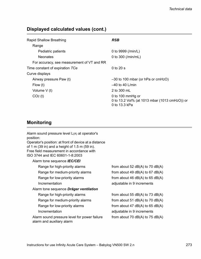
Instructions for use Infinity Acute Care System – Babylog VN500 SW 2.n 273
Technical data
Rapid Shallow Breathing RSB
Range
Pediatric patients 0 to 9999 (/min/L)
Neonates 0 to 300 (/min/mL)
For accuracy, see measurement of VT and RR
Time constant of expiration TCe 0 to 20 s
Curve displays
Airway pressure Paw (t) –30 to 100 mbar (or hPa or cmH2O)
Flow (t) –40 to 40 L/min
Volume V (t) 2 to 300 mL
CO2 (t) 0 to 100 mmHg or 0 to 13.2 Vol% (at 1013 mbar (1013 cmH2O)) or 0 to 13.3 kPa
Monitoring
Alarm sound pressure level L(A) at operator's position:Operator's position: at front of device at a distance of 1 m (39 in) and a height of 1.5 m (59 in).Free field measurement in accordance with ISO 3744 and IEC 60601-1-8:2003
Alarm tone sequence IEC/CEI
Range for high-priority alarms from about 52 dB(A) to 70 dB(A)
Range for medium-priority alarms from about 49 dB(A) to 67 dB(A)
Range for low-priority alarms from about 46 dB(A) to 65 dB(A)
Incrementation adjustable in 9 increments
Alarm tone sequence Dräger ventilation
Range for high-priority alarms from about 55 dB(A) to 73 dB(A)
Range for medium-priority alarms from about 51 dB(A) to 70 dB(A)
Range for low-priority alarms from about 47 dB(A) to 65 dB(A)
Incrementation adjustable in 9 increments
Alarm sound pressure level for power failure alarm and auxiliary alarm
from about 70 dB(A) to 75 dB(A)
Displayed calculated values (cont.)

Technical data
274 Instructions for use Infinity Acute Care System – Babylog VN500 SW 2.n
Sound pressure level LPA of alarm signals measured in accordance with IEC 60601-1-8 and A1:2012:
Alarm tone sequence IEC/CEI
Range for high-priority alarms according to volume setting
approx. 55 dB(A) to 72 dB(A)
Range for medium-priority alarms according to volume setting
approx. 52 dB(A) to 69 dB(A)
Range for low-priority alarms according to volume setting
approx. 49 dB(A) to 67 dB(A)
Incrementation adjustable in 9 increments
Alarm tone sequence Dräger ventilation
Range for high-priority alarms according to volume setting
approx. 55 dB(A) to 72 dB(A)
Range for medium-priority alarms according to volume setting
approx. 53 dB(A) to 70 dB(A)
Range for medium-priority alarms according to volume setting
approx. 45 dB(A) to 62 dB(A)
Incrementation adjustable in 9 increments
Range for power supply failure alarm and auxiliary alarm
approx. 70 dB(A) to 75 dB(A)
Delay time to sounding of auxiliary alarm if main alarm has failed
max. 18 s
Expiratory minute volume MVe
Upper alarm limit alarm if the upper alarm limit has been exceeded
Setting range in invasive ventilation 0.03 to 41 L/min
Setting range in non-invasive ventilation 0.03 to 60 L/min
Alarm delay MV delay
Pediatric patients 0 to 20 s
Neonates 0 to 15 s
Lower alarm limit alarm if the value has fallen below the lower alarm limit
Setting range 0.02 to 40 L/min, Off (with NIV or neonates)
Alarm suppression 2 minutes after leaving standby
during and 2 minutes after suction maneuver
2 minutes after switching on flow monitoring
Alarm delay MV delay
Pediatric patients 0 to 20 s
Neonates 0 to 15 s
Monitoring (cont.)

Instructions for use Infinity Acute Care System – Babylog VN500 SW 2.n 275
Technical data
Airway pressure Paw
Upper alarm limit alarm if the upper alarm limit has been exceeded
Setting range 7 to 105 mbar (or hPa or cmH2O)
Maximum airway pressure 120 mbar (or hPa or cmH2O)
Inspiratory O2 concentration FiO2
Upper alarm limit alarm after 30 seconds at the latest, if the upper alarm limit has been continuously exceeded
Lower alarm limit alarm after 30 seconds at the latest, if the lower alarm limit has been continuously undershot
Setting range both alarm limits are automatically assigned to the set value: under 60 Vol% with ±4 Vol%, from 60 Vol% with ±6 Vol%(lower alarm limit 18 Vol% at 21 Vol%)
End-expiratory CO2 concentration etCO2
Upper alarm limit alarm if the upper alarm limit has been exceeded
Setting range 1 to 98 mmHg (or 0.1 to 13.1 Vol% or 0.1 to 13.3 kPa)
Lower alarm limit alarm if the value has fallen below the lower alarm limit
Setting range 0 to 97 mmHg (or 0 to 13.0 Vol% or 0 to 13.2 kPa)
Respiratory rate RR
Upper alarm limit alarm if the respiratory rate (mandatory and spontaneous breaths) has been exceeded
Setting range 5 to 200/min, Off
Volume monitoring VT
Lower alarm limit alarm if the set tidal volume has not been supplied
Setting range 90 % of VT set (only for modes with VG)
Alarm suppression
Pediatric patients during the first five consecutive breaths where the applied inspiratory tidal volume has fallen below the lower alarm limit
Neonates during the first eight consecutive breaths where the applied inspiratory tidal volume has fallen below the lower alarm limit
Apnea alarm time Tapn
Alarm if no breathing activity is detected
Setting range 5 to 60 seconds, Off
Disconnect alarm delay time Tdisconnect
Setting range 0 to 60 seconds
Monitoring (cont.)

Technical data
276 Instructions for use Infinity Acute Care System – Babylog VN500 SW 2.n
Operating data
Protection class
Ventilation unit Babylog VN500Medical Cockpit Infinity C500Gas supply unit GS500Power supply unit PS500
Class I
CO2 sensor (sensor connected) Type BF
Proximal flow sensor (sensor connected) Type BF
Degree of protection against ingress of liquids and particles
IP21Protection against particles with a diameter of more than 12.5 mm (0.47 in)Protection against vertically dripping water
Mains power supply
Mains power connection 100 V to 240 V 50/60 Hz
Current consumption
at 230 V max. 1.4 A
at 100 V max. 3.0 A
Inrush current approx. 8 to 24 A peakapprox. 6 to 17 A quasi RMS
Power consumption
maximum 300 W
during ventilation, without charging the battery
approx. 100 W ventilation unit with Medical Cockpitapprox. 180 W with GS500
Device fuses
Range 100 V to 240 V F6.3H 250V IEC 60127-2/V (2 pcs.) Ventilation unit
Batteries
The operating time applies when the batteries are fully charged and new and ventilation is typical.
Low temperatures may reduce the operating time.
The charging time applies to new and completely discharged batteries when ventilation is typical and GS500 is not used. The actual charging time depends on the battery charge.
If GS500 is operating or the ambient temperature is high, the battery charging process may be restricted or interrupted.

Instructions for use Infinity Acute Care System – Babylog VN500 SW 2.n 277
Technical data
Typical ventilation
Ventilation mode PC-AC
FiO2 21 Vol%
PEEP 5 mbar (or hPa or cmH2O)
Pinsp 20 mbar (or hPa or cmH2O)
RR 60/min
Measured MV 400 mL/min
Ambient temperature 22 °C (71.6 °F)
Internal battery of ventilation unit (without PS500)
Type NiMH battery, sealed
Fuse F15A 80V UL248
Capacity 2.5 Ah
Voltage 24 V
Current 0 to 15 A
Operating time if mains power supply is not available
without GS500 30 minutes
with GS500 15 minutes
Charging
Charging time (to charge battery fully) <4 hours (<2 hours for 80 % charge)
Batteries of power supply unit PS500
Type VRLA batteries
Fuse triple F15A 80V UL248
Capacity 24 Ah
Voltage 24 V
Current 0 to 15 A
Operating time if mains power supply is not available
without GS500 240 minutes
with GS500 120 minutes
Charging
Charging time (to charge battery fully) <24 hours (<20 hours for 80 % charge)
Operating data (cont.)
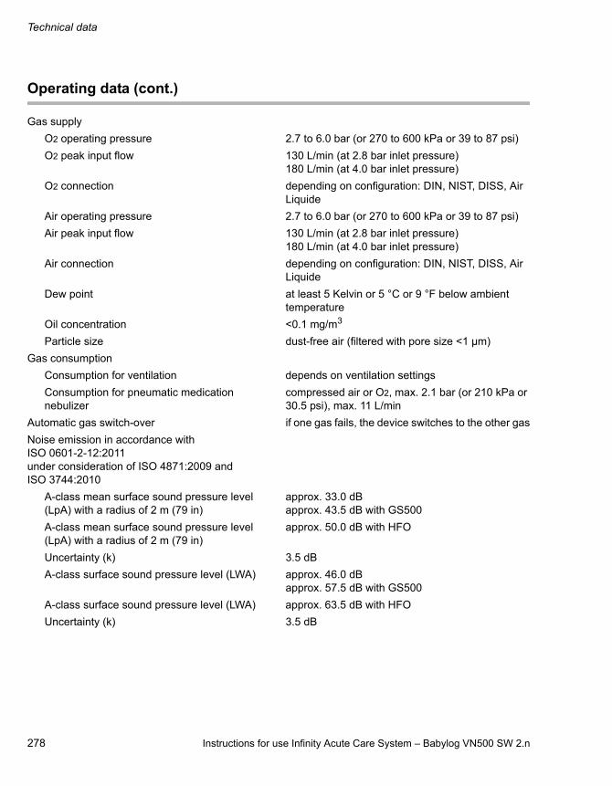
Technical data
278 Instructions for use Infinity Acute Care System – Babylog VN500 SW 2.n
Gas supply
O2 operating pressure 2.7 to 6.0 bar (or 270 to 600 kPa or 39 to 87 psi)
O2 peak input flow 130 L/min (at 2.8 bar inlet pressure)180 L/min (at 4.0 bar inlet pressure)
O2 connection depending on configuration: DIN, NIST, DISS, Air Liquide
Air operating pressure 2.7 to 6.0 bar (or 270 to 600 kPa or 39 to 87 psi)
Air peak input flow 130 L/min (at 2.8 bar inlet pressure)180 L/min (at 4.0 bar inlet pressure)
Air connection depending on configuration: DIN, NIST, DISS, Air Liquide
Dew point at least 5 Kelvin or 5 °C or 9 °F below ambient temperature
Oil concentration <0.1 mg/m3
Particle size dust-free air (filtered with pore size <1 µm)
Gas consumption
Consumption for ventilation depends on ventilation settings
Consumption for pneumatic medication nebulizer
compressed air or O2, max. 2.1 bar (or 210 kPa or 30.5 psi), max. 11 L/min
Automatic gas switch-over if one gas fails, the device switches to the other gas
Noise emission in accordance with ISO 0601-2-12:2011under consideration of ISO 4871:2009 and ISO 3744:2010
A-class mean surface sound pressure level(LpA) with a radius of 2 m (79 in)
approx. 33.0 dBapprox. 43.5 dB with GS500
A-class mean surface sound pressure level (LpA) with a radius of 2 m (79 in)
approx. 50.0 dB with HFO
Uncertainty (k) 3.5 dB
A-class surface sound pressure level (LWA) approx. 46.0 dBapprox. 57.5 dB with GS500
A-class surface sound pressure level (LWA) approx. 63.5 dB with HFO
Uncertainty (k) 3.5 dB
Operating data (cont.)

Instructions for use Infinity Acute Care System – Babylog VN500 SW 2.n 279
Technical data
Dimensions (W x H x D)
Babylog VN500 with lateral standard rail (without Infinity C500)
361 mm x 320 mm x 410 mm (14.3 in x 12.6 in x 16.1 in)
Babylog VN500 and Infinity C500 on the trolley, carrier frame without bar
577 mm x 1420 mm x 687 mm (22.7 in x 55.9 in x 27.1 in)
Babylog VN500 and Infinity C500 on the trolley, carrier frame with bar
577 mm x 1420 mm x 700 mm (22.7 in x 55.9 in x 27.6 in)
Weight
Ventilation unit approx. 17 kg (37.5 lb)
Medical Cockpit with holder approx. 8 kg (17.6 lb)
Trolley approx. 33 kg (72.8 lb)
Babylog VN500 and Infinity C500 approx. 25 kg (55.1 lb)
Babylog VN500 and Infinity C500 on trolley approx. 59 kg (130 lb)
PS500 approx. 27 kg (59.5 lb)
GS500 approx. 10.5 kg (23 lb)
Nominal weight (weight of ventilation unit and Medical Cockpit on trolley)
58 g (128 lb)
Maximum weight (permitted maximum total weight)
133 kg (293 lb)
Maximum load
Trolley 100 kg (220.5 lb)
Universal holder with standard rail (G93140) 10 kg (22 lb)
Humidifier holder (8416325) 5 kg (11 lb)
Humidifier holder (G93111) 5 kg (11 lb)
If a hinged arm is attached to the lateral standard rails of the ventilation unit in addition to the humidifier holder (8416325), the maximum load of 5 kg (11 lb) per lateral standard rail must be observed. The humidifier holder can then only support 4 kg (8.8 lb).
Electromagnetic compatibility EMC tested in accordance with IEC 60601-1-2
Classification according to Directive 93/42/EEC, Annex IX
II b
UMDNS code Universal Medical Device Nomenclature System – Nomenclature for medical devices
17-429
Operating data (cont.)
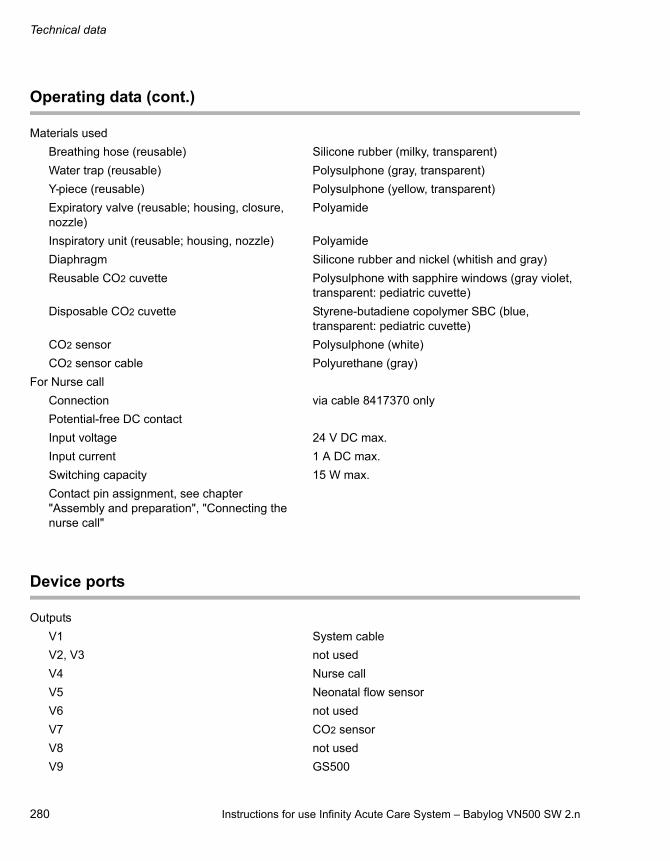
Technical data
280 Instructions for use Infinity Acute Care System – Babylog VN500 SW 2.n
Materials used
Breathing hose (reusable) Silicone rubber (milky, transparent)
Water trap (reusable) Polysulphone (gray, transparent)
Y-piece (reusable) Polysulphone (yellow, transparent)
Expiratory valve (reusable; housing, closure, nozzle)
Polyamide
Inspiratory unit (reusable; housing, nozzle) Polyamide
Diaphragm Silicone rubber and nickel (whitish and gray)
Reusable CO2 cuvette Polysulphone with sapphire windows (gray violet, transparent: pediatric cuvette)
Disposable CO2 cuvette Styrene-butadiene copolymer SBC (blue, transparent: pediatric cuvette)
CO2 sensor Polysulphone (white)
CO2 sensor cable Polyurethane (gray)
For Nurse call
Connection via cable 8417370 only
Potential-free DC contact
Input voltage 24 V DC max.
Input current 1 A DC max.
Switching capacity 15 W max.
Contact pin assignment, see chapter "Assembly and preparation", "Connecting the nurse call"
Device ports
Outputs
V1 System cable
V2, V3 not used
V4 Nurse call
V5 Neonatal flow sensor
V6 not used
V7 CO2 sensor
V8 not used
V9 GS500
Operating data (cont.)
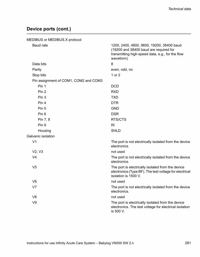
Instructions for use Infinity Acute Care System – Babylog VN500 SW 2.n 281
Technical data
MEDIBUS or MEDIBUS.X protocol
Baud rate 1200, 2400, 4800, 9600, 19200, 38400 baud (19200 and 38400 baud are required for transmitting high-speed data, e.g., for the flow waveform)
Data bits 8
Parity even, odd, no
Stop bits 1 or 2
Pin assignment of COM1, COM2 and COM3
Pin 1 DCD
Pin 2 RXD
Pin 3 TXD
Pin 4 DTR
Pin 5 GND
Pin 6 DSR
Pin 7, 8 RTS/CTS
Pin 9 RI
Housing SHLD
Galvanic isolation
V1 The port is not electrically isolated from the device electronics.
V2, V3 not used
V4 The port is not electrically isolated from the device electronics.
V5 The port is electrically isolated from the device electronics (Type BF). The test voltage for electrical isolation is 1500 V.
V6 not used
V7 The port is not electrically isolated from the device electronics.
V8 not used
V9 The port is electrically isolated from the device electronics. The test voltage for electrical isolation is 500 V.
Device ports (cont.)
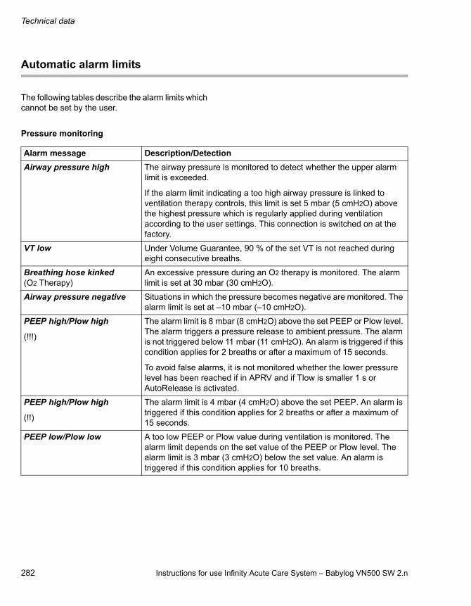
Technical data
282 Instructions for use Infinity Acute Care System – Babylog VN500 SW 2.n
Automatic alarm limits
The following tables describe the alarm limits which cannot be set by the user.
Pressure monitoring
Alarm message Description/Detection
Airway pressure high The airway pressure is monitored to detect whether the upper alarm limit is exceeded.
If the alarm limit indicating a too high airway pressure is linked to ventilation therapy controls, this limit is set 5 mbar (5 cmH2O) above the highest pressure which is regularly applied during ventilation according to the user settings. This connection is switched on at the factory.
VT low Under Volume Guarantee, 90 % of the set VT is not reached during eight consecutive breaths.
Breathing hose kinked(O2 Therapy)
An excessive pressure during an O2 therapy is monitored. The alarm limit is set at 30 mbar (30 cmH2O).
Airway pressure negative Situations in which the pressure becomes negative are monitored. The alarm limit is set at –10 mbar (–10 cmH2O).
PEEP high/Plow high
(!!!)
The alarm limit is 8 mbar (8 cmH2O) above the set PEEP or Plow level. The alarm triggers a pressure release to ambient pressure. The alarm is not triggered below 11 mbar (11 cmH2O). An alarm is triggered if this condition applies for 2 breaths or after a maximum of 15 seconds.
To avoid false alarms, it is not monitored whether the lower pressure level has been reached if in APRV and if Tlow is smaller 1 s or AutoRelease is activated.
PEEP high/Plow high
(!!)
The alarm limit is 4 mbar (4 cmH2O) above the set PEEP. An alarm is triggered if this condition applies for 2 breaths or after a maximum of 15 seconds.
PEEP low/Plow low A too low PEEP or Plow value during ventilation is monitored. The alarm limit depends on the set value of the PEEP or Plow level. The alarm limit is 3 mbar (3 cmH2O) below the set value. An alarm is triggered if this condition applies for 10 breaths.
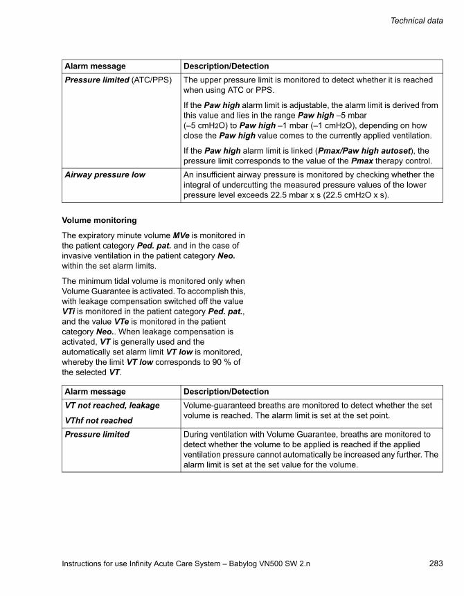
Instructions for use Infinity Acute Care System – Babylog VN500 SW 2.n 283
Technical data
Volume monitoring
The expiratory minute volume MVe is monitored in the patient category Ped. pat. and in the case of invasive ventilation in the patient category Neo. within the set alarm limits.
The minimum tidal volume is monitored only when Volume Guarantee is activated. To accomplish this, with leakage compensation switched off the value VTi is monitored in the patient category Ped. pat., and the value VTe is monitored in the patient category Neo.. When leakage compensation is activated, VT is generally used and the automatically set alarm limit VT low is monitored, whereby the limit VT low corresponds to 90 % of the selected VT.
Pressure limited (ATC/PPS) The upper pressure limit is monitored to detect whether it is reached when using ATC or PPS.
If the Paw high alarm limit is adjustable, the alarm limit is derived from this value and lies in the range Paw high –5 mbar (–5 cmH2O) to Paw high –1 mbar (–1 cmH2O), depending on how close the Paw high value comes to the currently applied ventilation.
If the Paw high alarm limit is linked (Pmax/Paw high autoset), the pressure limit corresponds to the value of the Pmax therapy control.
Airway pressure low An insufficient airway pressure is monitored by checking whether the integral of undercutting the measured pressure values of the lower pressure level exceeds 22.5 mbar x s (22.5 cmH2O x s).
Alarm message Description/Detection
Alarm message Description/Detection
VT not reached, leakage
VThf not reached
Volume-guaranteed breaths are monitored to detect whether the set volume is reached. The alarm limit is set at the set point.
Pressure limited During ventilation with Volume Guarantee, breaths are monitored to detect whether the volume to be applied is reached if the applied ventilation pressure cannot automatically be increased any further. The alarm limit is set at the set value for the volume.

Technical data
284 Instructions for use Infinity Acute Care System – Babylog VN500 SW 2.n
Monitoring of the breathing circuit and the patient connection
Alarm message Description/Detection
Disconnection? Disconnection is monitored by checking that the mandatory breaths reach a minimum pressure level. The alarm limit is derived from the set points for ventilation.
During pressure-controlled ventilation, the alarm is triggered when the airway pressure is lower than the lower pressure level plus 50 % of the pressure difference between the upper and lower pressure levels.
During pressure-supported ventilation, the alarm is triggered when the airway pressure is lower than the lower pressure level plus 30 % of the pressure difference between the upper and lower pressure levels.
During ventilation with Volume Guarantee and volume support, the limit is 50 % of the pressure difference between the upper pressure level and the lower pressure level currently calculated by Babylog VN500.
During volume-controlled ventilation, the pressure level is 5 mbar (5 cmH2O) above PEEP.
All pressure criteria become ineffective if a sufficient expiration has been detected.
In the event of an excessive inspiratory flow at the current airway pressure, a disconnection due to excessive inspiratory volume is detected. This volume depends on the patient category:– 1.5 L in the Ped. pat. patient category– 0.5 L in the Neo. patient category
Leakage Leakages are monitored in the Ped. pat. patient category. The alarm limit is set at 55 % of relative Leakage. Leakages during NIV are not monitored.
Airway obstructed? Obstructions in the breathing circuit are monitored by observing the flow delivered to the patient during a defined period.

Instructions for use Infinity Acute Care System – Babylog VN500 SW 2.n 285
Technical data
FiO2 monitoring
CO2 monitoring
Essential performance characteristics
The essential performance consists in a controlled and monitored patient ventilation with user-defined settings for the monitoring functions– minimum and maximum tidal volume,– maximum airway pressure,– minimum and maximum O2 concentration in the
breathing gas,
or, if a set limit is exceeded, an appropriate alarm.
Additionally, the integrated monitoring alarms in the following situations:– Failure of the external power supply– Battery discharge– Failure of the gas supply
Alarm message Description/Detection
FiO2 high An excessive O2 concentration of the applied gas is monitored.
The alarm limit is 4 Vol% above the set value if this is less than or equal to 60 Vol%.
The alarm limit is 6 Vol% above the set value if this is greater than 60 Vol%.
FiO2 low An insufficient O2 concentration of the applied gas is monitored.
For an FiO2 concentration of 21 Vol% the alarm limit is 18 Vol%.
The alarm limit is 4 Vol% below the set value if this is greater than 21 Vol% and less than or equal to 60 Vol%.
The alarm limit is 6 Vol% below the set value if this is greater than 60 Vol%.
Alarm message Description/Detection
CO2 sensor? The correct functioning of the CO2 sensor is monitored. An alarm is immediately generated in the event of a technical defect or if a sensor is not connected.
An alarm is generated after 60 s if the sensor is removed from the cuvette or the sensor does not detect any breathing activity.

Technical data
286 Instructions for use Infinity Acute Care System – Babylog VN500 SW 2.n
Connections to IT networks
In an IT network, data can be exchanged by means of wired or wireless technologies. An IT network can be any data interface (e.g., RS232, LAN, USB, printer interface) that is described in standards and conventions.
During operation, this device can exchange information with other devices by means of IT networks and supports the following functions:
– Display of waveforms and parameter data
– Signaling of alarms
– Transfer of device settings and patient data
– Service mode, access to logbooks
Connecting this device to a network that incorporates other devices or making subsequent changes to that network can lead to new risks for patients, users, and third parties. Before the device is connected to the network or the network is changed, these risks must be identified, analyzed, and evaluated, and appropriate measures taken.
Examples of subsequent changes to the network:
– Changing the network configuration
– Removing devices from the network
– Adding new devices to the network
– Performing upgrades or updates on devices that are connected to the network
Information on connecting to the network
Prerequisites
This device must only be connected to the network by service personnel. The IT representative of the hospital must be consulted in advance.
The following documents must be observed:
– Accompanying documents of this device
– Description of the network interface
– Description of the network-based alarm systems
Dräger recommends complying with IEC 80001-1 (risk management for IT networks with medical devices).
Serial interfaces
The following interfaces are supported:
– RS232 interfaces conforming to EIA RS232 (CCITT V.24/V.28) for the following applications:– MEDIBUS, MEDIBUS.X– Connection to medical devices from other
manufacturers

Instructions for use Infinity Acute Care System – Babylog VN500 SW 2.n 287
Technical data
Consequences of using an unsuitable network
If the network does not meet the requirements, dangerous situations can result. The following situations can occur with this device:
– Due to an insecure decentralized alarm system:– Alarms or data are transmitted at the wrong
time.– Alarms are not transmitted.
– During an interruption of the network connection:
– Suppressed alarms or alarm tones are not reactivated, but remain suppressed.
– Alarms are not transmitted.
– Without firewall and antivirus software:– Data are not protected.– Device settings are changed.– The device generates false alarms or no
alarms.
– Data are sent incomplete, sent to the wrong device, or not sent at all.
– Patient data are intercepted, falsified, or damaged.
– Data have incorrect time stamps.
Requirements for the electrical characteristics of connected devices and networks
The analog and digital ports are only appropriate for connecting devices or networks that have a nominal voltage on the network side of max. 24 V DC and meet the requirements of one of the following standards:
– IEC 60950-1: Ungrounded SELV circuits
– IEC 60601-1 (as of 2nd edition): Touchable secondary circuits
Open-source software
Dräger devices that use software may use open-source software, depending on their setup. Open-source software may be subject to different terms of license. Additional information regarding the open-source software used in this device is available at the following web page:
www.draeger.com/opensource

288 Instructions for use Infinity Acute Care System – Babylog VN500 SW 2.n
This page has been left blank intentionally.

Instructions for use Infinity Acute Care System – Babylog VN500 SW 2.n 289
Principles of operation
Principles of operation
Description of the ventilation modes . . . . . . 290
PC-CMV . . . . . . . . . . . . . . . . . . . . . . . . . . . . . . 290PC-SIMV. . . . . . . . . . . . . . . . . . . . . . . . . . . . . . 291PC-AC . . . . . . . . . . . . . . . . . . . . . . . . . . . . . . . 293PC-PSV . . . . . . . . . . . . . . . . . . . . . . . . . . . . . . 294PC-MMV. . . . . . . . . . . . . . . . . . . . . . . . . . . . . . 295PC-HFO . . . . . . . . . . . . . . . . . . . . . . . . . . . . . . 296PC-APRV . . . . . . . . . . . . . . . . . . . . . . . . . . . . . 298SPN-CPAP/PS . . . . . . . . . . . . . . . . . . . . . . . . . 299SPN-CPAP/VS . . . . . . . . . . . . . . . . . . . . . . . . . 300SPN-CPAP . . . . . . . . . . . . . . . . . . . . . . . . . . . . 301SPN-PPS . . . . . . . . . . . . . . . . . . . . . . . . . . . . . 302
Additional settings for ventilation . . . . . . . . 304
Apnea Ventilation . . . . . . . . . . . . . . . . . . . . . . . 304Flow trigger. . . . . . . . . . . . . . . . . . . . . . . . . . . . 306Inspiratory termination . . . . . . . . . . . . . . . . . . . 307Sigh . . . . . . . . . . . . . . . . . . . . . . . . . . . . . . . . . 308HFO sigh . . . . . . . . . . . . . . . . . . . . . . . . . . . . . 309Volume Guarantee . . . . . . . . . . . . . . . . . . . . . . 310Volume Guarantee (HFO). . . . . . . . . . . . . . . . . 312ATC. . . . . . . . . . . . . . . . . . . . . . . . . . . . . . . . . . 312AutoRelease. . . . . . . . . . . . . . . . . . . . . . . . . . . 315
Special functions . . . . . . . . . . . . . . . . . . . . . . 316
Medication nebulization . . . . . . . . . . . . . . . . . . 316C20/C . . . . . . . . . . . . . . . . . . . . . . . . . . . . . . . . 317Smart Pulmonary View . . . . . . . . . . . . . . . . . . . 318
Description of the therapy types. . . . . . . . . . 319
O2 therapy . . . . . . . . . . . . . . . . . . . . . . . . . . . . 319NIV – Non-invasive ventilation . . . . . . . . . . . . . 319
Automatic leakage compensation . . . . . . . . 320
Flow reduction Anti Air Shower . . . . . . . . . . 321
Measurements . . . . . . . . . . . . . . . . . . . . . . . . 322
Measurement principles . . . . . . . . . . . . . . . . . . 322Airway pressure measurement. . . . . . . . . . . . . 323
Battery concept . . . . . . . . . . . . . . . . . . . . . . . 324
General information. . . . . . . . . . . . . . . . . . . . . 324Display of battery charge. . . . . . . . . . . . . . . . . 324Battery ageing . . . . . . . . . . . . . . . . . . . . . . . . . 324Alarm behavior in battery operation . . . . . . . . 325
Pneumatic functional description . . . . . . . . 328
Main menu bar structure . . . . . . . . . . . . . . . 331
Factory-set screen views . . . . . . . . . . . . . . . 335
List of references . . . . . . . . . . . . . . . . . . . . . 336
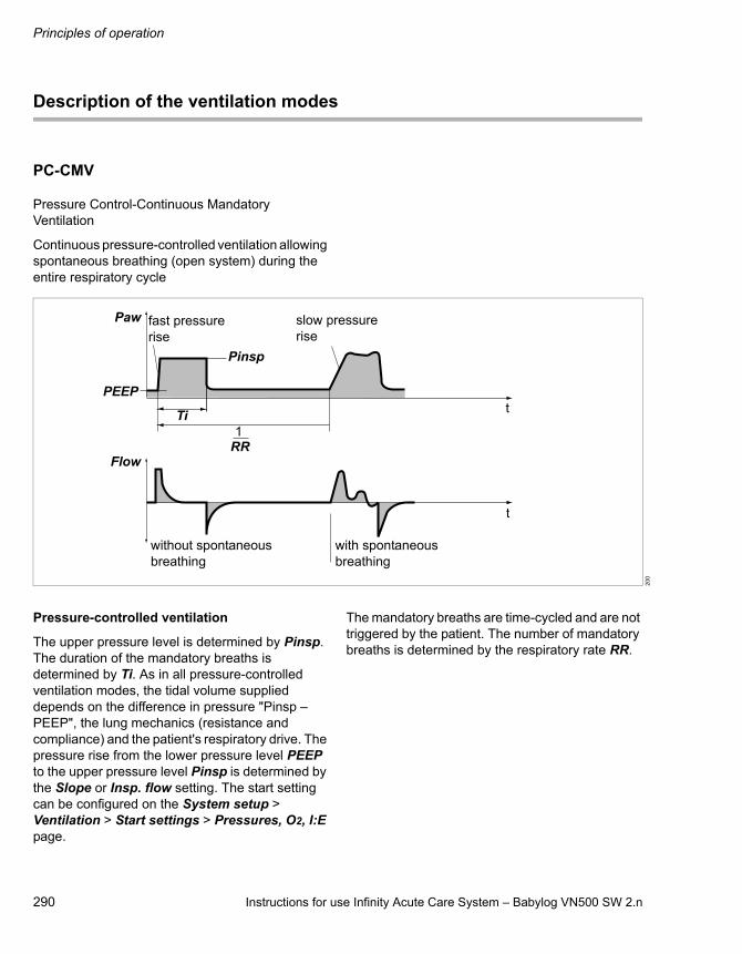
Principles of operation
290 Instructions for use Infinity Acute Care System – Babylog VN500 SW 2.n
Description of the ventilation modes
PC-CMV
Pressure Control-Continuous Mandatory Ventilation
Continuous pressure-controlled ventilation allowing spontaneous breathing (open system) during the entire respiratory cycle
Pressure-controlled ventilation
The upper pressure level is determined by Pinsp. The duration of the mandatory breaths is determined by Ti. As in all pressure-controlled ventilation modes, the tidal volume supplied depends on the difference in pressure "Pinsp – PEEP", the lung mechanics (resistance and compliance) and the patient's respiratory drive. The pressure rise from the lower pressure level PEEP to the upper pressure level Pinsp is determined by the Slope or Insp. flow setting. The start setting can be configured on the System setup > Ventilation > Start settings > Pressures, O2, I:E page.
The mandatory breaths are time-cycled and are not triggered by the patient. The number of mandatory breaths is determined by the respiratory rate RR.
20
0
without spontaneous breathing
fast pressure rise
slow pressure rise
with spontaneous breathing
PEEP
Paw
Flow
Pinsp
Ti
RR1
t
t

Instructions for use Infinity Acute Care System – Babylog VN500 SW 2.n 291
Principles of operation
PC-SIMV
Pressure Control-Synchronized Intermittent Mandatory Ventilation
Intermittent, triggered, pressure-controlled ventilation allowing spontaneous breathing (open system) during the entire respiratory cycle
Pressure-controlled ventilation
The upper pressure level is determined by Pinsp. The duration of the mandatory breaths is determined by Ti. As in all pressure-controlled ventilation modes, the tidal volume supplied depends on the difference in pressure "Pinsp –PEEP", the lung mechanics (resistance and
compliance) and the patient's respiratory drive. The pressure rise from the lower pressure level PEEP to the upper pressure level Pinsp is determined by the Slope or Insp. flow setting. The start setting can be configured on the System setup > Ventilation > Start settings > Pressures, O2, I:E page.
In the Neo. patient category, this mode is not available with non-invasive ventilation.
Synchronization
The mandatory breaths can be triggered by the patient's inspiratory effort from the PEEP level. By setting the trigger level, the mandatory breaths can be synchronized with the patient's inspiratory efforts.
A mandatory breath can only be triggered within a "trigger window" by the flow trigger in synchrony with the patient's spontaneous inspiratory effort. This prevents the mandatory breath being applied during expiration.
The trigger window is 1.5 seconds long. For expiratory times shorter than 1.5 seconds, the trigger window covers the entire expiratory time minus a refractory period for the previous expiration.
20
1
Pressure support PS
with spontaneous breathing
without spontaneous breathing
Trigger window for insp. synchronization
fast pressure rise
slow pressure rise fast pressure
riseslow pressure rise
PEEP
Paw
Pinsp
Flow
Ti
RR1
t
t

Principles of operation
292 Instructions for use Infinity Acute Care System – Babylog VN500 SW 2.n
Synchronization of mandatory breaths reduces the expiratory time. Babylog VN500 extends the subsequent expiratory time or spontaneous breathing time by the missing time. This prevents an increase of the mandatory respiratory rate.
The number of mandatory breaths is determined by the respiratory rate RR.
Pressure support
During spontaneous breathing from the PEEP level, the patient can be supported with PS. Every inspiratory effort of the patient that meets the trigger criteria triggers a pressure-supported breath. By setting the trigger level, the patient's inspiratory efforts are synchronized. The time, number, and duration of pressure-supported breaths is determined by the patient's spontaneous breathing.
As in all pressure-controlled ventilation modes, the tidal volume supplied depends on the difference in pressure "Psupp – PEEP", the lung mechanics (resistance and compliance) and the patient's respiratory drive. The pressure rise from the lower pressure level PEEP to the upper pressure level Psupp is determined by the Slope or Insp. flow setting. The start setting can be configured on the System setup > Ventilation > Start settings > Pressures, O2, I:E page.
The pressure support is terminated as soon as the inspiratory flow falls below 15 % of the maximum inspiratory flow.
The pressure support is also terminated as soon as the duration of the support has reached the maximum inspiratory time. For intubated patients, the maximum inspiratory time in the Ped. pat. patient category is limited to 1.5 seconds. In the Neo. patient category, the maximum inspiratory time is limited to 130 % of Ti, maximum of 1.5 seconds.

Instructions for use Infinity Acute Care System – Babylog VN500 SW 2.n 293
Principles of operation
PC-AC
Pressure Control-Assist Control
Assist-controlled, pressure-controlled ventilation allowing spontaneous breathing during the entire respiratory cycle and backup respiratory rate
Pressure-controlled ventilation
The upper pressure level is determined by Pinsp. The duration of the mandatory breaths is determined by Ti. As in all pressure-controlled ventilation modes, the tidal volume supplied depends on the difference in pressure "Pinsp – PEEP", the lung mechanics (resistance and compliance) and the patient's respiratory drive. The pressure rise from the lower pressure level PEEP to the upper pressure level Pinsp is determined by the Slope or Insp. flow setting. The start setting can be configured on the System setup > Ventilation > Start settings > Pressures, O2, I:E page.
In the Neo. patient category, this mode is not available with non-invasive ventilation.
Assisted-controlled ventilation
Every inspiratory effort of the patient from the PEEP level triggers a synchronized mandatory breath. Thus, the time and number of mandatory breaths are determined by the patient. The trigger window covers the expiratory time minus a refractory period for the previous expiration. The expiratory time is determined by the respiratory rate RR and the inspiratory time Ti. A non-synchronized mandatory breath is triggered at the latest at the end of the expiratory time (back-up respiratory rate).
The minimum number of mandatory breaths is determined by the respiratory rate RR.
20
2
with spontaneous breathing
without spontaneous breathing
fast pressure rise
slow pressure rise
Trigger window for insp. synchronization
PEEP
Paw
Flow
Pinsp
Ti
RR1
t
t

Principles of operation
294 Instructions for use Infinity Acute Care System – Babylog VN500 SW 2.n
PC-PSV
Pressure Control-Pressure Support Ventilation
Pressure-controlled ventilation with guaranteed minimum respiratory rate (backup respiratory rate)
Pressure support
During spontaneous breathing from the PEEP level, the patient can be supported with PS. The level of pressure support is determined by Pinsp. Every inspiratory effort of the patient that meets the trigger criteria triggers a pressure-supported breath. By setting the trigger level, the patient's inspiratory efforts are synchronized. The time, number, and duration of pressure-supported breaths is determined by the patient's spontaneous breathing. If the patient's respiratory rate is less than the set back-up respiratory rate RR or there is no spontaneous breathing present, the device administers pressure-supported breaths with the respiratory rate RR.
As in all pressure-controlled ventilation modes, the tidal volume supplied depends on the difference in pressure "Pinsp – PEEP", the lung mechanics (resistance and compliance) and the patient's respiratory drive. The pressure rise from the lower pressure level PEEP to the upper pressure level Pinsp is determined by the Slope or Insp. flow
setting. The start setting can be configured on the System setup > Ventilation > Start settings > Pressures, O2, I:E page.
The pressure support is terminated as soon as the inspiratory flow falls below 15 % of the maximum inspiratory flow, see "Inspiratory termination" on page 307.
The pressure support is also terminated as soon as the duration of the support has reached the maximum inspiratory time.
For intubated patients, the maximum inspiratory time in the Ped. pat. patient category is limited to 1.5 seconds. For the Neo. patient category, the maximum inspiratory time can be set with Timax to a maximum of 1.5 seconds.
In the case of non-invasive ventilation, the maximum duration of a breath for the Ped. pat. patient category can be set with Timax. In the Neo. patient category, this mode is not available with non-invasive ventilation.
31
0
fast pressure rise
slow pressure rise
Spontaneous breathing with pressure support PS
Paw
Flow
PEEP
Inspiratory termination criterion
t
t
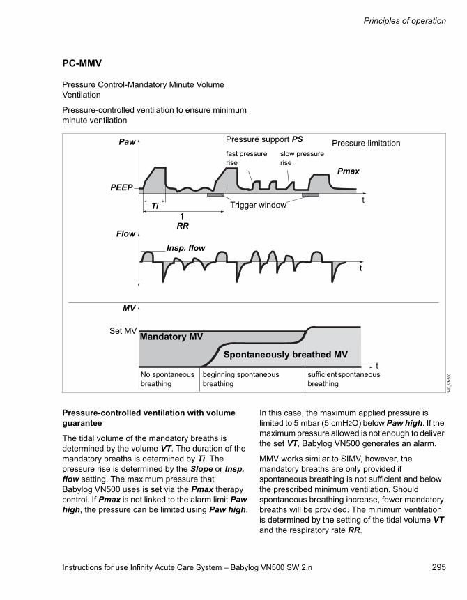
Instructions for use Infinity Acute Care System – Babylog VN500 SW 2.n 295
Principles of operation
PC-MMV
Pressure Control-Mandatory Minute Volume Ventilation
Pressure-controlled ventilation to ensure minimum minute ventilation
Pressure-controlled ventilation with volume guarantee
The tidal volume of the mandatory breaths is determined by the volume VT. The duration of the mandatory breaths is determined by Ti. The pressure rise is determined by the Slope or Insp. flow setting. The maximum pressure that Babylog VN500 uses is set via the Pmax therapy control. If Pmax is not linked to the alarm limit Paw high, the pressure can be limited using Paw high.
In this case, the maximum applied pressure is limited to 5 mbar (5 cmH2O) below Paw high. If the maximum pressure allowed is not enough to deliver the set VT, Babylog VN500 generates an alarm.
MMV works similar to SIMV, however, the mandatory breaths are only provided if spontaneous breathing is not sufficient and below the prescribed minimum ventilation. Should spontaneous breathing increase, fewer mandatory breaths will be provided. The minimum ventilation is determined by the setting of the tidal volume VT and the respiratory rate RR.
34
0_
VN
50
0No spontaneous breathing
beginning spontaneous breathing
sufficient spontaneous breathing
fast pressure rise
Pressure support PS
Insp. flow
PEEP
Paw
Pmax
Flow
slow pressure rise
Pressure limitation
MV
Ti
Set MV
Trigger window
Mandatory MV
Spontaneously breathed MV
RR1
t
t
t

Principles of operation
296 Instructions for use Infinity Acute Care System – Babylog VN500 SW 2.n
The maximum number of mandatory breaths is determined by the respiratory rate RR. However, this number is only provided when there is insufficient spontaneous breathing or an apnea is present.
Pressure support
During spontaneous breathing from the PEEP level, the patient can be supported with PS. Every inspiratory effort of the patient that meets the trigger criteria triggers a pressure-supported breath. By setting the trigger level, the patient's inspiratory efforts are synchronized. The time, number, and duration of pressure-supported breaths is determined by the patient's spontaneous breathing.
As in all pressure-controlled ventilation modes, the tidal volume supplied depends on the difference in pressure "Psupp – PEEP", the lung mechanics (resistance and compliance) and the patient's
respiratory drive. The pressure rise from the lower pressure level PEEP to the upper pressure level Psupp is determined by the Slope or Insp. flow setting. The start setting can be configured on the System setup > Ventilation > Start settings > Pressures, O2, I:E page.
The pressure support is terminated as soon as the inspiratory flow falls below 15 % of the maximum inspiratory flow.
The pressure support is also terminated as soon as the duration of the support has reached the maximum inspiratory time. For intubated patients, the maximum inspiratory time in the Ped. pat. patient category is limited to 1.5 seconds. In the Neo. patient category, the maximum inspiratory time is limited to 130 % of Ti, maximum of 1.5 seconds.
In the Neo. patient category, this mode is not available with non-invasive ventilation.
PC-HFO
Pressure Control-High Frequency Oscillation
Continuous pressure-controlled ventilation with high-frequency oscillations at the mean pressure level
Ventilation with high-frequency pressure oscillations enables gas to be exchanged in the lungs despite very small tidal volumes (often in the
dead space volume range). While pressure amplitudes may be considerable in the breathing circuit, only small fluctuations occur around the
311
_V
N5
00
Flow
Paw
t
t
MAPhf
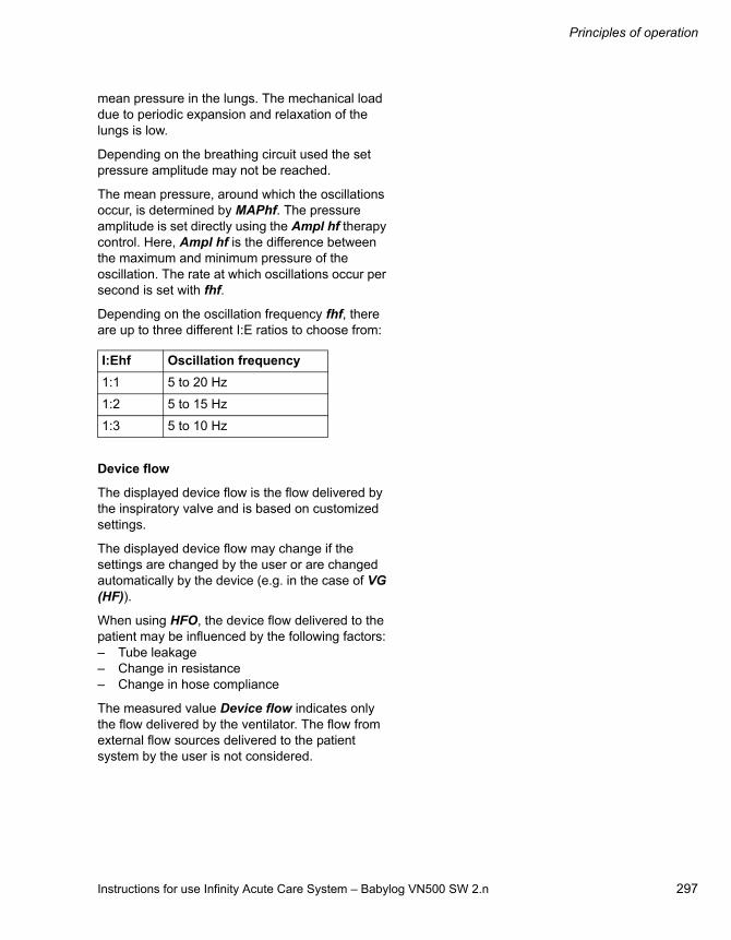
Instructions for use Infinity Acute Care System – Babylog VN500 SW 2.n 297
Principles of operation
mean pressure in the lungs. The mechanical load due to periodic expansion and relaxation of the lungs is low.
Depending on the breathing circuit used the set pressure amplitude may not be reached.
The mean pressure, around which the oscillations occur, is determined by MAPhf. The pressure amplitude is set directly using the Ampl hf therapy control. Here, Ampl hf is the difference between the maximum and minimum pressure of the oscillation. The rate at which oscillations occur per second is set with fhf.
Depending on the oscillation frequency fhf, there are up to three different I:E ratios to choose from:
Device flow
The displayed device flow is the flow delivered by the inspiratory valve and is based on customized settings.
The displayed device flow may change if the settings are changed by the user or are changed automatically by the device (e.g. in the case of VG (HF)).
When using HFO, the device flow delivered to the patient may be influenced by the following factors:– Tube leakage– Change in resistance– Change in hose compliance
The measured value Device flow indicates only the flow delivered by the ventilator. The flow from external flow sources delivered to the patient system by the user is not considered.
I:Ehf Oscillation frequency
1:1 5 to 20 Hz
1:2 5 to 15 Hz
1:3 5 to 10 Hz

Principles of operation
298 Instructions for use Infinity Acute Care System – Babylog VN500 SW 2.n
PC-APRV
Pressure Control-Airway Pressure Release Ventilation
Spontaneous breathing under continuous positive airway pressure with brief pressure releases
The patient breathes spontaneously at a high pressure level Phigh for an adjustable length of time Thigh. For very short expiratory times Tlow, Babylog VN500 switches to a low pressure level Plow. The normal lung areas are emptied, but the "slow" lung areas only change volume to a lesser extent*.
The number of pressure releases is determined by the Thigh and Tlow settings. The releases are time-cycled and are not triggered by the patient. The duration is determined by Tlow. The tidal volume exchanged during the release phases depends on the difference in pressure Phigh – Plow, the lung mechanics (resistance and compliance) and the length of pressure release Tlow. The pressure rise from the lower pressure level Plow to the upper pressure level Phigh is determined by the Slope or Insp. flow setting.
The start setting can be configured on the System setup > Ventilation > Start settings > Pressures, O2, I:E page.
When AutoRelease is activated, the duration of pressure releases is determined by the expiratory flow trace. The Exp. term. setting determines the percentage by which the expiratory flow must fall short in relation to the peak flow for the ventilation to return to the high pressure level.
When AutoRelease is switched on, the change-over from the upper pressure level Phigh to the lower pressure level Plow is synchronized with the patient's spontaneous breathing.
Synchronization of the mandatory breath reduces the time on the upper pressure level. Babylog VN500 prolongs the subsequent ventilation time on the upper pressure level by the missing time. This prevents an increase in respiratory rate.
In the Neo. patient category, this mode is not available with non-invasive ventilation.
20
3
Paw
Flow
Phigh
Plow
Thigh
Tlow
t
t
* References [1], [2], [3], [4], see page 336.

Instructions for use Infinity Acute Care System – Babylog VN500 SW 2.n 299
Principles of operation
SPN-CPAP/PS
Spontaneous-Continuous Positive Airway Pressure/Pressure Support
Spontaneous breathing with continuous positive pressure level with or without pressure support
When the pressure support is not switched on, the patient's spontaneous breathing is merely supported by an increased PEEP.
During spontaneous breathing from the PEEP level, the patient can be supported with PS. Every inspiratory effort of the patient that meets the trigger criteria triggers a pressure-supported breath. The time, number, and duration of pressure-supported breaths is determined by the patient's spontaneous breathing.
As in all pressure-controlled ventilation modes, the tidal volume supplied depends on the difference in pressure "Psupp – PEEP", the lung mechanics (resistance and compliance) and the patient's respiratory drive. The pressure rise from the lower pressure level PEEP to the upper pressure level Psupp is determined by the Slope or Insp. flow setting. The start setting can be configured on the System setup > Ventilation > Start settings > Pressures, O2, I:E page.
The pressure support is terminated as soon as the inspiratory flow falls below 15 % of the maximum inspiratory flow.
The pressure support is also terminated as soon as the duration of the support has reached the maximum inspiratory time. For intubated patients, the maximum inspiratory time in the Ped. pat. patient category is limited to 1.5 seconds. For the Neo. patient category, the maximum inspiratory time can be set with Timax to a maximum of 1.5 seconds. In the case of non-invasive ventilation, the maximum duration of support for the Ped. pat. patient category can be set with Timax.
In the Neo. patient category, this mode is not available with non-invasive ventilation.
20
9
fast pressure rise
slow pressure rise
Spontaneous breathing with pressure support PS
Paw
Flow
PEEP
Inspiratory termination criterion
t
t

Principles of operation
300 Instructions for use Infinity Acute Care System – Babylog VN500 SW 2.n
SPN-CPAP/VS
Spontaneous-Continuous Positive Airway Pressure/Volume Support
Spontaneous breathing with continuous positive pressure level with or without volume support
For volume support VS, every inspiratory effort by the patient on the PEEP level that meets the trigger criteria triggers a volume-supported breath. By setting the trigger level, the patient's inspiratory efforts are synchronized. The time, number and duration of volume-supported breaths is determined by the patient's spontaneous breathing. The pressure rise is determined by the Slope or Insp. flow setting. The start setting can be configured on the System setup > Ventilation > Start settings > Pressures, O2, I:E page.
The volume support is terminated as soon as the inspiratory flow falls below 15 % of the maximum inspiratory flow.
The volume support is also terminated as soon as the duration of the support has reached the maximum inspiratory time. For intubated patients, the maximum inspiratory time in the Ped. pat. patient category is limited to 1.5 seconds. For the Neo. patient category, the maximum inspiratory time can be set with Timax to a maximum of 1.5 seconds. In the case of non-invasive ventilation, the maximum duration of support for the Ped. pat. patient category can be set with Timax.
In the Neo. patient category, this mode is not available with non-invasive ventilation.
The set tidal volume of the supported breaths is reached through the automatically controlled pressure level of the volume support. With volume support, the support pressure is automatically adjusted to changes in lung conditions (resistance and compliance) and to the spontaneous breathing demand of the patient.
If Paw high is linked to the Pmax therapy control, set the maximum pressure that can be applied with the Pmax setting!
If Paw high is not linked to the Pmax therapy control, always set the Paw high alarm limit so that Babylog VN500 generates an alarm in the event of an increase in airway pressure due to reduced compliance. The maximum pressure that can be applied is limited to 5 mbar (5 cmH2O) below the upper alarm limit.
21
0
Inspiratory termination criterion
PEEP
Paw
Flow
t
t

Instructions for use Infinity Acute Care System – Babylog VN500 SW 2.n 301
Principles of operation
SPN-CPAP
Spontaneous-Continuous Positive Airway Pressure
Spontaneous breathing with continuous positive pressure level in the application mode NIV
The SPN-CPAP ventilation mode is only available with non-invasive ventilation in the Neo. patient category.
The patient's spontaneous breathing is supported with an increased PEEP.
For the Manual inspiration/hold maneuver, the pressure of the breath is set with the PmanInsp therapy control and the duration of the breath is set with the TmanInsp therapy control.
35
4
Paw
Flow
PEEP
t
t
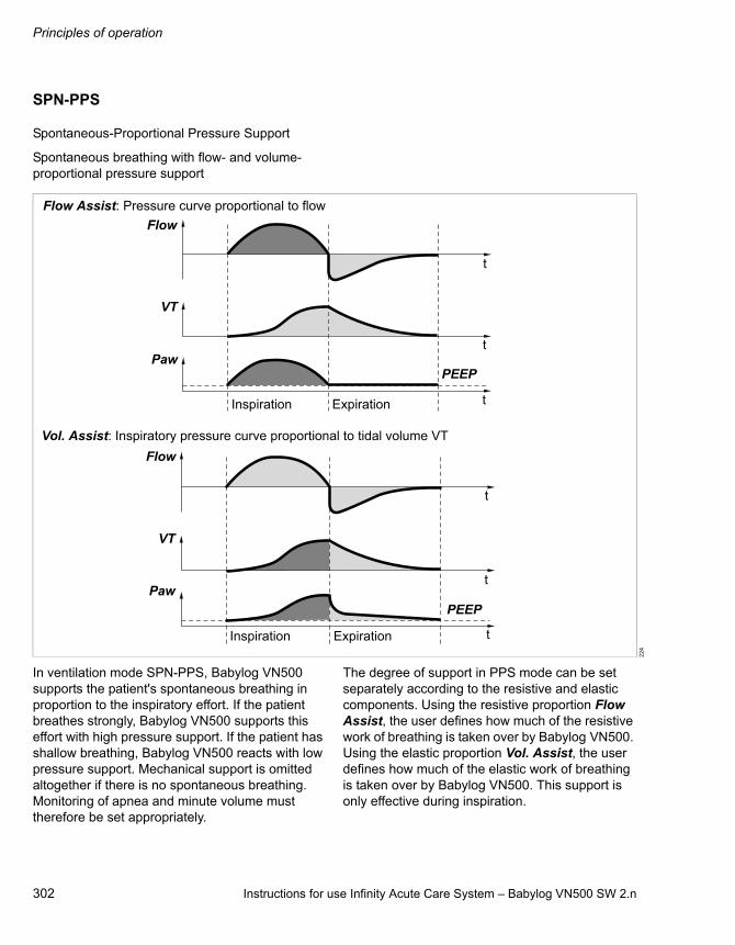
Principles of operation
302 Instructions for use Infinity Acute Care System – Babylog VN500 SW 2.n
SPN-PPS
Spontaneous-Proportional Pressure Support
Spontaneous breathing with flow- and volume-proportional pressure support
In ventilation mode SPN-PPS, Babylog VN500 supports the patient's spontaneous breathing in proportion to the inspiratory effort. If the patient breathes strongly, Babylog VN500 supports this effort with high pressure support. If the patient has shallow breathing, Babylog VN500 reacts with low pressure support. Mechanical support is omitted altogether if there is no spontaneous breathing. Monitoring of apnea and minute volume must therefore be set appropriately.
The degree of support in PPS mode can be set separately according to the resistive and elastic components. Using the resistive proportion Flow Assist, the user defines how much of the resistive work of breathing is taken over by Babylog VN500. Using the elastic proportion Vol. Assist, the user defines how much of the elastic work of breathing is taken over by Babylog VN500. This support is only effective during inspiration.
22
4
Paw
Paw
Flow
Flow
VT
VT
PEEP
PEEP
Flow Assist: Pressure curve proportional to flow
Vol. Assist: Inspiratory pressure curve proportional to tidal volume VT
Inspiration Expiration
Inspiration Expiration
t
t
t
t
t
t

Instructions for use Infinity Acute Care System – Babylog VN500 SW 2.n 303
Principles of operation
The tidal volume is limited by the VTmax setting in order to protect the patient from excessive tidal volumes in case of sudden leakages or incorrectly set PPS. If VTmax is reached, the breath is stopped and an expiration is started. Babylog VN500 displays the alarm message VT limited. If leakage compensation is activated, the leakage-compensated tidal volume is used. If leakage compensation is deactivated, the tidal volume measured on the inspiratory side is used. The start-up value for VTmax corresponds to 130 % of the preconfigured tidal volume.
The pressure support is terminated as soon as the inspiratory flow falls below 15 % of the maximum inspiratory flow.
The pressure support is also terminated as soon as the duration of the support has reached the maximum inspiratory time. For intubated patients, the maximum inspiratory time in the Ped. pat. patient category is limited to 1.5 seconds. For the Neo. patient category, the maximum inspiratory time can be set with Timax to a maximum of 1.5 seconds. In the case of non-invasive ventilation, the maximum duration of support for the Ped. pat. patient category can be set with Timax.
In the Neo. patient category, this mode is not available with non-invasive ventilation.
If Paw high is linked to the Pmax therapy control, set the maximum pressure that can be applied with the Pmax setting!
If Paw high is not linked to the Pmax therapy control, always set the Paw high alarm limit so that Babylog VN500 generates an alarm in the event of an increase in airway pressure due to reduced compliance. The maximum pressure that can be applied is limited to 5 mbar (5 cmH2O) below the upper alarm limit.

Principles of operation
304 Instructions for use Infinity Acute Care System – Babylog VN500 SW 2.n
Additional settings for ventilation
Apnea Ventilation
For switching over automatically to volume-guaranteed mandatory ventilation in case of apnea.
For Babylog VN500 to be able to detect an apnea, flow measurement with the neonatal flow sensor must function and flow monitoring with the neonatal flow sensor must be activated.
Babylog VN500 detects an apnea when no expiratory flow is measured or insufficient inspiratory gas is delivered during the set apnea alarm time Tapn. If apnea ventilation is activated, the device starts volume-guaranteed ventilation with the ventilation parameters RRapn and VTapn. The inspiratory time for apnea ventilation is determined from the set apnea respiratory rate RRapn and a fixed I:E ratio of 1:2.
The patient can breathe spontaneously and the mandatory breaths are synchronized with the patient's spontaneous breathing. The apnea ventilation respiratory rate RRapn remains constant. Babylog VN500 provides synchronized intermittent mandatory ventilation.
Apnea ventilation is terminated by touching the Apn. Vent. reset button. Babylog VN500 continues ventilating in the previously set ventilation mode. Changing the ventilation mode or the additional settings, e.g. PS, also terminates apnea ventilation.
If an apnea situation generating an alarm occurs again during apnea ventilation, this indicates that the apnea ventilation respiratory rate RRapn has been set too low in relation to apnea alarm time Tapn.
31
7
Spontaneous breathing with pressure support
Start Apnea Ventilation
Apnea alarm time Tapn
Paw
PEEP
FlowRRapn
1
t
t

Instructions for use Infinity Acute Care System – Babylog VN500 SW 2.n 305
Principles of operation
Automatic return from apnea ventilation
If the Automatic return from Apnea Ventilation function is configured, then the device automatically switches to the previous ventilation mode when sufficient spontaneous breathing is resumed. The following conditions must be met:– Apnea ventilation must have been active for at
least 2 minutes.– The alarm message MV low is not active.– One of the following conditions must
additionally be met:– The ratio of MVespon to MVe is greater than
25 % and the ratio of MVleak to MVe is less than 40 %.Or
– 80 % of the mandatory breaths are triggered spontaneously.
If apnea reoccurs within 3 minutes following automatic termination of apnea ventilation in the Ped. pat. patient category, the Automatic return from Apnea Ventilation function is disabled until apnea ventilation is terminated manually or another ventilation mode is selected.
For configuration of the Automatic return from Apnea Ventilation function, see "Configuring general settings" on page 177.
Principles of operation
306 Instructions for use Infinity Acute Care System – Babylog VN500 SW 2.n
Flow trigger
The flow trigger is used to synchronize mandatory or pressure-supported breaths with spontaneous breathing. The flow trigger is also used to trigger breaths with SPN-CPAP/PS and SPN-CPAP/VS.
With the Flow trigger threshold, the mandatory breaths are synchronized with the inspiratory efforts. The start setting of the flow trigger can be configured on the System setup > Ventilation > Start settings > VT, RR, Trigger page.
Spontaneous breathing activity by the patient is indicated on the screen by the brief appearance of the symbol.
The flow trigger is automatically leakage compensated.
In order to prevent a possible error when measuring the respiratory rate, e.g., caused by cardiogenic oscillations, only those spontaneous breaths are counted which meet the adjustable trigger criterion.
23
0
Paw
PEEP
Trigger threshold
Flow
Spontaneousbreathing
t
t

Instructions for use Infinity Acute Care System – Babylog VN500 SW 2.n 307
Principles of operation
Inspiratory termination
For spontaneous breaths supported with PS, VS and PPS, the length of inspiration is determined by the inspiratory termination criterion. Inspiratory termination specifies at which percentage of the peak inspiratory flow expiration is to start.
This value is set at 15 % by default and is automatically leakage-compensated.
22
8
Inspiratory termination criterion
Paw
Flow
Start of inspiration End of inspirationt
t

Principles of operation
308 Instructions for use Infinity Acute Care System – Babylog VN500 SW 2.n
Sigh
Atelectasis can be prevented by activating the sigh function and setting the sigh in the form of an intermittent PEEP. The purpose of expiratory sigh is to open collapsed areas of the lungs or to keep open "more dependent" areas of the lungs.
The sigh function can be activated in all ventilation modes with mandatory breaths, except for PC-APRV. When the sigh function is activated, the end-expiratory pressure PEEP increases by the set value of the intermittent PEEP.
The time between the two sigh phases can be set with the therapy control Interval sigh.
The therapy control Cycles sigh controls how many respiratory cycles are covered by the sigh phase. The average airway pressure is higher, and a longer filling time is normally available.
During pressure-controlled ventilation, the inspiratory pressures Pinsp, Psupp increase by the amount intPEEP.
22
0
Interval sighPaw
PEEP
intPEEP
Cycles sigh
t

Instructions for use Infinity Acute Care System – Babylog VN500 SW 2.n 309
Principles of operation
HFO sigh
A sigh (RRsigh) can be set during high-frequency oscillation.
RRsigh determines how often per minute the sigh is to occur. A conventional pressure-controlled breath is applied with pressure Psigh. The duration of this breath is set with Tisigh. The high-frequency oscillations are discontinued for at least 150 ms prior to the sigh and are resumed 250 ms after the sigh. The high-frequency oscillations start with an expiration.
Rise time and rise form of the sigh are determined by the configuration Slope adjustment (Slope or Insp. flow). If Insp. flow is configured, a constant time slope of 0.1 second is set for Tisigh.
The sigh can also be triggered with the Man. insp./hold function. The duration of the sigh is determined by touching and holding the Man. insp./hold button.
31
3_
VN
50
0
Paw
Flow
MAPhf
t
t
Tisigh
Psigh

Principles of operation
310 Instructions for use Infinity Acute Care System – Babylog VN500 SW 2.n
Volume Guarantee
The mandatory breaths are volume controlled with the Volume Guarantee additional setting. To apply the set tidal volume, Babylog VN500 controls the inspiratory plateau pressure Pinsp.
Changes in lung conditions (compliance, resistance) are compensated. The tidal volume of the mandatory breaths remains constant.
Volume Guarantee can be switched on in the PC-SIMV, PC-CMV, PC-AC and PC-PSV ventilation modes. In the PC-MMV and SPN-CPAP/VS ventilation modes, volume guarantee is always available.
The advantage in contrast to time-cycled, pressure-limited ventilation, is that changes in lung conditions (compliance, resistance) have no impact on the tidal volume. If, for example, compliance increases, the inspiratory pressure decreases automatically. If, for instance, compliance decreases, then pressure rises but only up to the set pressure limit Pmax.
If Pmax is not linked to the alarm limit Paw high, Babylog VN500 increases Pinsp up to a maximum of 5 mbar (5 cmH2O) below the set alarm limit Paw high.
Fluctuations in spontaneous breathing are also compensated. The greater the patient's inspiratory efforts are, the lower the pressure Babylog VN500 applies. Thus with Volume Guarantee, Babylog VN500 always ventilates with just the right pressure required for the tidal volume desired. The pressure load on the lungs is limited to the extent absolutely necessary.
Without Volume Guarantee, the user must adjust the inspiratory pressure to reach the tidal volume desired.
The control works in the range PEEP + 0.1 mbar (0.1 cmH2O) to Pmax (or Paw high – 5 mbar (5 cmH2O)) for spontaneous breaths. For triggered mandatory breaths, the control works in the range PEEP + 3 mbar (3 cmH2O) to Pmax (or Paw high – 5 mbar (5 cmH2O)).
22
5
Pinsp = f (VT, C)
without spontaneous breathing
with spontaneous breathing
Paw highPaw
PEEP
Flow
VT
Ti Te
RR1
t
t

Instructions for use Infinity Acute Care System – Babylog VN500 SW 2.n 311
Principles of operation
Using the setting for Pmax or the alarm limit Paw high – 5 mbar (5 cmH2O), the user limits the maximum pressure of the device.
The set tidal volume cannot be applied under these conditions:– Pmax is insufficient– The inspiratory pressure pattern has no plateau
because the flow is too low or the inspiratory time Ti is too short.
A set inspiratory time Ti shorter than the lung filling time can be recognized from the flow curve. The flow at the end of the inspiratory time has not dropped to zero. In this case, it must be decided whether the current condition of the patient permits prolongation of the inspiratory time Ti in order to reduce peak pressure even further. This effect can also be caused during ventilation, e.g., due to a build-up of secretion. In this situation, the pressure is limited by Babylog VN500 as described.
If the tidal volume measured is below 90 % of the set tidal volume, Babylog VN500 generates an alarm.
The control occurs gradually from breath to breath. The tidal volume is measured, then compared to the set tidal volume and a new plateau pressure is calculated for the next breath. After a change to the set tidal volume, the inspiratory pressure required for this is reached after just a few breaths.
In the Neo. patient category, the tidal volume measured on the expiratory side is taken as a basis for the control. In the Ped. pat. patient category, the inspiratory tidal volume is used. If leakage compensation is activated, the leakage-compensated tidal volume is used for the control.
The minimum inspiratory pressure for mandatory non-triggered breaths is 3 mbar (3 cmH2O) above PEEP; for triggered mandatory and pressure-supported spontaneous breaths it is 0.1 mbar (0.1 cmH2O) above PEEP.
In case of major tube leakage, the actual tidal volume in the patient's lungs can (as in other ventilation modes also) be larger than the tidal volume measured on the expiratory side. Then the inspiratory and expiratory tidal volumes are different. If, in the course of an inspiration, the
delivered and measured VT exceeds the set VT by an amount dependent on the actual leakage rate, Babylog VN500 terminates the inspiration and starts the expiration.
If the flow sensor fails, ventilation is continued with the pressure used last and Babylog VN500 generates an alarm.
Set the alarm limits MV high and MV low appropriately in order to avoid excessive or insufficient flow following rapid changes in compliance. When using Volume Guarantee, activate flow monitoring!
If the Volume Guarantee function in the Ped. pat. and Neo. categories is switched on and a manual inspiration (Man. insp./hold) is triggered, a breath is applied to the maximum pressure Pmax.
Start-up procedure with volume guarantee
When the Volume Guarantee function is switched on, Babylog VN500 applies the set tidal volume VT by delivering a pressure-controlled breath with an inspiratory pressure of 5 mbar (5 cmH2O) above the set PEEP. Babylog VN500 measures the applied volume in this case and calculates an initial target pressure for the set volume. The next mandatory breath is applied with an inspiratory pressure that corresponds to 75 % of this target pressure. Babylog VN500 measures the applied volume again and calculates a new target pressure for the set volume. The next mandatory breath is applied with this target pressure. As described above, the following mandatory breaths are changed in the inspiratory pressure so that the set volume is reached on average.

Principles of operation
312 Instructions for use Infinity Acute Care System – Babylog VN500 SW 2.n
Volume Guarantee (HFO)
With the volume guarantee of the high-frequency oscillation (VG (HF)), Babylog VN500 calculates the amplitudes required to reach the set tidal volume VThf. The Ampl hf therapy control is inactive when volume guarantee is switched on. If the set VThf is not reached, Babylog VN500 generates an alarm.
ATC
Automatic Tube Compensation
Compensation of the tube resistance
ATC regulates the airway pressure to the tracheal level. This function calculates and displays the tracheal pressure on the basis of a mathematical tube model, the set tube type and the inner diameter of the tube.
When tube compensation is activated, Babylog VN500 displays the calculated tracheal pressure in the pressure curve together with the pressure at the Y-piece as a line. Activated tube compensation is indicated by ATC and the tube diameter in the page header bar.
When selecting loops, tracheal pressure can also be selected as a parameter. Tracheal pressure can also be displayed when tube compensation is deactivated if the calculation of the tracheal pressure was activated on the Start/Standby > Tube/NIV page and the tube type and diameter were entered. Babylog VN500 uses this value for calculating leakage and determining the lung mechanics, but not for tube compensation.
22
6
Pressure at Y-piece
Tracheal pressure
Paw
Flow
PEEP
Ptrach
t
t

Instructions for use Infinity Acute Care System – Babylog VN500 SW 2.n 313
Principles of operation
The selected degree of compensation is not considered when displaying tracheal pressure or when determining leakage and lung mechanics.
Calculating tracheal pressure
Babylog VN500 calculates tracheal pressure on the basis of a square function of tube resistance and patient flow.
The selected tube type and the inner diameter of the tube must correspond with the real tube for correct calculation and display of the tracheal pressure. This is required for correct tube compensation.
When tube compensation is activated, the ventilation pressure in the breathing circuit is increased during inspiration or decreased during expiration. The airway pressure is adjusted to the tracheal level if 100 % compensation of the tube resistance has been selected.
Expiratory tube compensation can be deactivated.
For the mandatory portion of the breath, the inspiratory tube compensation can be deactivated.
When tube compensation is activated, Babylog VN500 controls the ventilation pressure so that the resistive work of breathing on the tube is compensated in accordance with the selected degree of compensation.
Depending on the direction of the patient flow, the airway pressure is increased during inspiration or decreased during expiration.
The airway pressure can be reduced to a minimum of 0 mbar (0 cmH2O).
The maximum value for the airway pressure can be set using the Pmax therapy control. If Pmax is not linked to the alarm limit Paw high, the maximum pressure is limited to 5 mbar (5 cmH2O) below the alarm limit Paw high. The pressure limitation message is displayed when the maximum permitted values are reached.
If the value selected for Paw high or Pmax is too low, it may impair the effectiveness of tube compensation. If the value selected for Paw high or Pmax is too high, it may result in unwanted high airway pressures. When setting Pmax, be aware that this value may actually be reached in contrast to the value for Paw high.
Calculating the support
The level of support Paw applied during ATC is calculated on the basis of a square law function of tube resistance and patient flow.
Tube coefficient
The tube coefficient KTube is largely determined on the basis of the results obtained by Guttmann et al*.
The tube coefficient KTube for the full-length tube is always taken as the basis. The effect of the shortened length is negligible.
PTrachea = Paw – KTube x Flow x |Flow|
PTrachea: Pressure in the trachea
Paw: Pressure at the Y-piece of the breathing circuit
KTube: Tube coefficient (see page 314)
Flow: Patient flow
Inspiration: Flow >0
Expiration: Flow <0
Paw = Comp. x KTube x Flow x |Flow|
Comp.: Degree of compensation 0 to 100 %
KTube: Tube coefficient (see page 314)
Flow: Patient flow
* Literature reference [5], see page 336
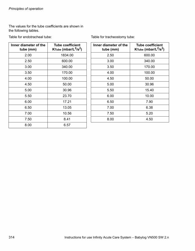
Principles of operation
314 Instructions for use Infinity Acute Care System – Babylog VN500 SW 2.n
The values for the tube coefficients are shown in the following tables.
Table for endotracheal tube: Table for tracheostomy tube:
Inner diameter of the tube (mm)
Tube coefficientKTube (mbar/L2/s2)
2.00 1834.00
2.50 600.00
3.00 340.00
3.50 170.00
4.00 100.00
4.50 50.00
5.00 30.96
5.50 23.70
6.00 17.21
6.50 13.05
7.00 10.56
7.50 8.41
8.00 6.57
Inner diameter of the tube (mm)
Tube coefficientKTube (mbar/L2/s2)
2.50 600.00
3.00 340.00
3.50 170.00
4.00 100.00
4.50 50.00
5.00 30.96
5.50 15.40
6.00 10.00
6.50 7.90
7.00 6.38
7.50 5.20
8.00 4.50
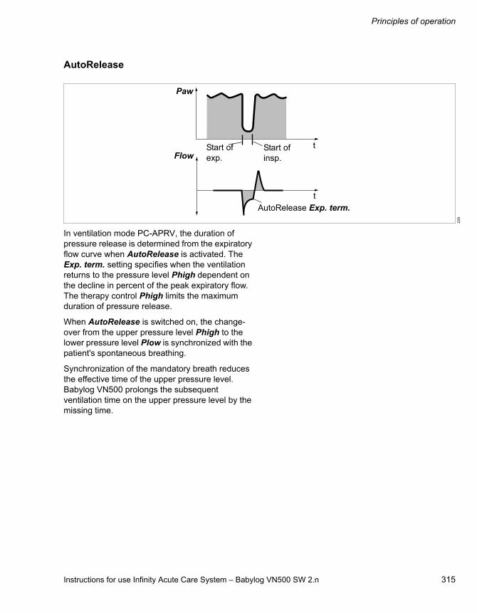
Instructions for use Infinity Acute Care System – Babylog VN500 SW 2.n 315
Principles of operation
AutoRelease
In ventilation mode PC-APRV, the duration of pressure release is determined from the expiratory flow curve when AutoRelease is activated. The Exp. term. setting specifies when the ventilation returns to the pressure level Phigh dependent on the decline in percent of the peak expiratory flow. The therapy control Phigh limits the maximum duration of pressure release.
When AutoRelease is switched on, the change-over from the upper pressure level Phigh to the lower pressure level Plow is synchronized with the patient's spontaneous breathing.
Synchronization of the mandatory breath reduces the effective time of the upper pressure level. Babylog VN500 prolongs the subsequent ventilation time on the upper pressure level by the missing time.
22
9
AutoRelease Exp. term.
Paw
FlowStart of insp.
Start of exp.
t
t
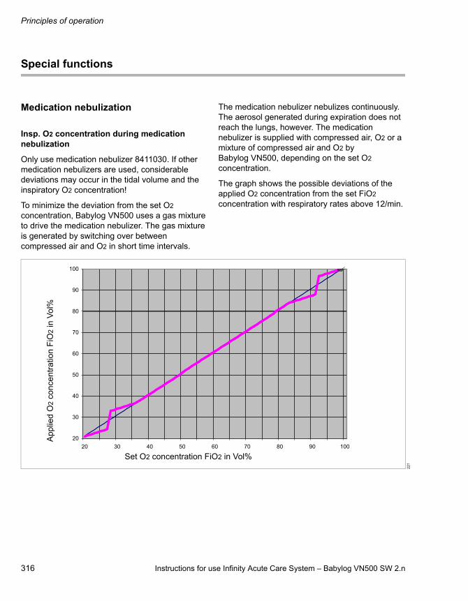
Principles of operation
316 Instructions for use Infinity Acute Care System – Babylog VN500 SW 2.n
Special functions
Medication nebulization
Insp. O2 concentration during medication nebulization
Only use medication nebulizer 8411030. If other medication nebulizers are used, considerable deviations may occur in the tidal volume and the inspiratory O2 concentration!
To minimize the deviation from the set O2 concentration, Babylog VN500 uses a gas mixture to drive the medication nebulizer. The gas mixture is generated by switching over between compressed air and O2 in short time intervals.
The medication nebulizer nebulizes continuously. The aerosol generated during expiration does not reach the lungs, however. The medication nebulizer is supplied with compressed air, O2 or a mixture of compressed air and O2 by Babylog VN500, depending on the set O2 concentration.
The graph shows the possible deviations of the applied O2 concentration from the set FiO2 concentration with respiratory rates above 12/min.
22
1
Set O2 concentration FiO2 in Vol%
App
lied
O2
con
cent
ratio
n F
iO2 in
Vo
l%

Instructions for use Infinity Acute Care System – Babylog VN500 SW 2.n 317
Principles of operation
Air supply from the GS500 gas supply unit
If Babylog VN500 is supplied with Air from the GS500 gas supply unit and O2 is supplied from the central gas supply system, the medication nebulizer operates with O2 only. The measured value FiO2 indicates the O2 concentration of the gas supplied at the inspiratory port and not the O2 concentration reaching the patient. Depending on the patient category, the following systematic deviations are possible:
C20/C
The C20/C index is a calculation of the compliance of the last 20 % (C20) of a breath in relation to the compliance (C) of the entire breath.
During a breath, Babylog VN500 determines continuously the pressure applied and the resulting tidal volume. The compliance of the last 20 % of a breath determined in this manner is set in proportion to the total compliance.
From the ratio determined, the following information can be derived:
– C20/C <1: A decrease of compliance at the end of the breath was detected. The lungs may be overinflated.
– C20/C >1: An increase of compliance at the end of the breath was detected. Tidal recruitment may be occurring.
– C20/C = 1: No change in compliance at the end of a breath could be detected. The lungs may not be overinflated, or tidal recruitment may not be occurring.
The calculation of C20/C takes into account the effect of the resistance of the endotracheal tube used or the tracheostomy tube used. For this, the tube diameter is required. The correct tube diameter entry of the tube used determines the quality of the C20/C index calculated.
The C20/C index is always displayed as long as a correction delivers plausible results with regard to the resistance. If, for instance, a smaller tube diameter was entered than that of the tube actually used, a correction to the measured values may deliver an implausible result. In this case, no C20/C index is displayed. The parameter field remains empty.
Ped. pat. up to +30 Vol%
Neo. up to +30 Vol%

Principles of operation
318 Instructions for use Infinity Acute Care System – Babylog VN500 SW 2.n
Smart Pulmonary View
Graphic display of lung characteristics
Smart Pulmonary View is a graphic display of lung flexibility (compliance) and resistance of the airways (resistance).
The representation corresponds to the displayed measured values of the respective patient.
The display range of compliance is 0 to 400 mL/mbar (400 mL/cmH2O).
The display range of resistance is 0 to 300 mbar/L/s (300 cmH2O/L/s).
To detect an improvement or deterioration of the patient's condition with regard to compliance and resistance, it is possible to adapt the representation to the current values of the patient. One measuring range starts at 0 and goes to double the value of the current compliance; the other measuring range starts at 0 and goes to double the value of the current resistance. After the adaptation, the measuring values determined are displayed as reference values with the time and date. In the graph, the current values (calibration values) are displayed as an orange broken line. The scales for compliance and resistance are adapted.
The compliance and resistance measured respectively are displayed by thin or thick lines accordingly.
The point when the maximum value that is based on the last calibration is reached is represented with a red line as a boundary. This indicates that the measured values determined can no longer be represented graphically. The measured values are outside the display range. Babylog VN500 displays a request for a new calibration.
The diaphragm is displayed schematically underneath the representation of the lungs. The movement of the diaphragm indicates synchronized mandatory breaths, supported (triggered) breaths, or spontaneous breaths.
The ratio between spontaneous breathing and mandatory ventilation is displayed in a diagram:
– RRspon and VTspon represent the spontaneous minute volume as an area
– RRmand and VTmand represent the mandatory minute volume as an area
The display is a qualitative representation of the respective minute volume.
From this, the following information can be derived:
– The ratio between the spontaneous and mandatory minute volumes
– The quality and pattern of the spontaneous breathing, e.g., Rapid Shallow Breathing
Smart Pulmonary View is a qualitative representation of the ventilation situation. Local pathophysiological peculiarities, such as atelectasis or airway obstructions of the lungs, cannot be displayed.
Furthermore, individual patient situations cannot be displayed, such as the condition after a pneumectomy or a diaphragmatic hernia.

Instructions for use Infinity Acute Care System – Babylog VN500 SW 2.n 319
Principles of operation
Description of the therapy types
O2 therapy
O2 therapy can be used for patients with independent breathing. The continuous flow is applied via an oxygen mask, a hood, or nasal cannula. The O2 concentration and the flow can be set.
NIV – Non-invasive ventilation
Non-invasive ventilation by prongs or mask for patients with spontaneous breathing
Leakages are greater with non-invasive ventilation than with invasive ventilation. Babylog VN500 takes into account the leakages in the NIV application mode accordingly.
The Tdisconnect setting can be used to delay the Airway pressure low alarm.
In the Neo. patient category, only the SPN-CPAP or PC-CMV ventilation modes may be selected. When using prongs or a mask, the neonatal flow sensor must be removed from the breathing circuit. Babylog VN500 switches off flow monitoring with the neonatal flow sensor.
Principles of operation
320 Instructions for use Infinity Acute Care System – Babylog VN500 SW 2.n
Automatic leakage compensation
Mode of operation
Babylog VN500 determines the difference between the delivered inspiratory flow and the measured expiratory flow. This difference provides a measure of the amount of leakage and is displayed by Babylog VN500 as the leakage minute volume MVleak and relatively as % leak (MVleak to MVi).
The calculation of leakage compensation takes into account the airway pressures. A higher percentage of volume is lost on the inspiratory side than on the expiratory side because the pressure during inspiration is higher. The displayed leakage minute volume MVleak is based on the mean pressure Pmean. The leakage minute volume MVleak also takes the inspiratory leakages into account. Due to technical tolerances, a small leakage minute volume may be displayed even if the tube leakage is closed. If there is a rapid change in the leakage, e.g., due to the leak being opened or closed suddenly, Babylog VN500 needs a few breaths to identify the new leakage value. Babylog VN500 prevents any potentially dangerous rises in pressure which might occur as a result of this.
The inspiratory flow trigger threshold and the inspiratory termination criterion are applied to the leakage-compensated flow, with both settings being continuously optimized with regards to the leakage. This automatic adjustment also takes place if leakage compensation is deactivated.
If leakage compensation is activated, the values measured for volume and flow as well as the curves for flow and volume are displayed with leakage correction, with the exception of the minute volume measured during expiration and all measured values which are explicitly marked as inspiratory or expiratory, such as VTi and VTe.
Activate or deactivate leakage compensation on the System setup > Ventilation > General settings page.
Example of leakage compensation with flow trigger or inspiratory termination criterion
The mode of operation is illustrated using a simplified example with the following values:– Flow trigger setting 0.2 L/min– Leakage increases from 0 % to 20 %
Mode of operation with leakage compensation:Babylog VN500 determines the leakage flow. The leakage flow is subtracted from the total flow in order to determine the patient flow. Only this flow is used for the flow trigger or the inspiratory termination criterion. After a few breaths Babylog VN500 "learns" the leakage and avoids auto-triggering. If the leakage is closed, the sensitivity of the flow trigger is automatically increased again. The same applies to the inspiratory termination criterion for breaths with pressure support or volume support.
Leakage rate
Babylog VN500 determines the mean leakage flow from the difference between inspiratory minute volume MVi and expiratory minute volume MVe (displayed as MV). Standardized as MVi, the result is the leakage rate displayed in percent:
Leakage rate = 100 % x (MVi – MVe) / MVi

Instructions for use Infinity Acute Care System – Babylog VN500 SW 2.n 321
Principles of operation
Flow reduction Anti Air Shower
When the Anti Air Shower function is activated and a disconnection is detected during ventilation, the flow is reduced until reconnection is detected. The Disconnection? alarm is displayed at the same time. With non-invasive ventilation, the time before the alarm is triggered can be delayed with Tdisconnect. The minute ventilation can be reduced due to the already reduced flow.
To configure the Anti Air Shower function, see "Configuring general settings" on page 177.

Principles of operation
322 Instructions for use Infinity Acute Care System – Babylog VN500 SW 2.n
Measurements
Measurement principles
Measurement principle of the flow measurement
The measurement principle used for flow measurement is based on hot-wire anemometry. Hot-wire anemometry is a thermal measurement procedure in which the measuring wires of the flow sensor are kept at a constant excess temperature. The higher the flow, the more current is required to maintain a constant excess temperature. The flow rate is calculated based on the magnitude of the heating current.
To ensure correct function, check for visible damage, soiling, and particles before inserting the flow sensor. Repeat this check regularly. Replace flow sensors when damaged, soiled, or not particle-free. If the measurement wires of the flow sensor glow continuously during operation, this is an indication of contamination. Immediately reprocess or replace the flow sensor.
Flow measurement with neonatal flow sensor
The flow is measured with a hot wire anemometer between the Y-piece and the tube. The flow direction is detected by the use of two hot wires, one of which is shielded on one side.
The amount of energy required to maintain the wire at a temperature of 400 °C (752 °F) is used as a measure of the flow passing through the sensor, cooling the hot wire in the process.
The lowest flow at which detection functions reliably is 0.2 L/min. Lower flow values are therefore suppressed and displayed as zero.
Two different sensor types are available:– Y-sensor, integrated in the Y-piece– ISO sensor to insert between Y-piece and tube
connector
Both sensor types use the same sensor insert. Despite this, the sensor properties are not identical. The sensor type is set in the Sensors/Parameters > Neonatal flow sensor dialog window in order to adapt the measurement for this type of sensor optimally.
O2 measurement
A heating and a temperature sensor are positioned in a homogeneous magnetic field which is periodically activated and deactivated. The thermal conductivity of O2 changes due to the magnetic field. The change in thermal conductivity is a measure of the O2 concentration.
CO2 measurement
CO2 is measured via a mainstream system based on absorption measurement.
A light source generates a spectrum. Two light detectors record the characteristic absorption spectrum and supply electrical signals that change with the CO2 concentration.
These signals are then evaluated and displayed. Heating the CO2 sensor probe prevents condensation.
Instructions for use Infinity Acute Care System – Babylog VN500 SW 2.n 323
Principles of operation
Airway pressure measurement
Babylog VN500 measures the airway pressure indirectly by means of two internal pressure sensors. The sensors are installed in the inspiratory and expiratory lines, thereby eliminating the need for an external pressure measuring line between the Y-piece and the device. As long as one side is without flow, the measured value of the flowless pressure sensor corresponds to the airway pressure at the Y-piece.
During ventilation, there is a constant base flow. However, due to this constant base flow, the zero-flow condition is never attained either on the inspiratory or expiratory side. The pressure measured by the inspiratory pressure sensor varies with the variations in airway pressure but is increased by the pressure drop in the inspiratory line of the breathing circuit. The pressure measured by the expiratory pressure sensor is reduced by the pressure drop in the expiratory line of the breathing circuit. These pressure differences are caused by the flow resistance of the breathing circuit.
During expiration, the value measured at the inspiratory pressure sensor (Pinsp) is reduced by the pressure drop caused by the base flow (Flowbf) in the inspiratory line of the breathing circuit (Rinsp):
Paw = Pinsp – Rinsp x Flowbf
During inspiration, the value measured by the expiratory pressure sensor (Pexp) is raised relative to the airway pressure by the pressure drop caused by the flow (normally Flowout Flowbf) in the expiratory line of the breathing circuit (Rexp):
Paw = Pexp + Rexp x Flowout
The hose resistances are determined by Babylog VN500 during the breathing circuit check.
The user can configure whether the setting occurs via the pressure ramp Slope with a base flow of 6L/min or with an adjustable inspiratory flow Insp. flow and an expiratory base flow of 6 L/min.
Adaptation to ambient conditions
The volume of a gas depends on the ambient conditions with regard to temperature, pressure, and humidity. In lung physiology, reference is made to the conditions inside the lungs for the values of minute volume and tidal volume: 37 °C (99 °F) body temperature, pressure inside the lungs, 100 % relative humidity.
Measured values for flow and volume under these conditions are characterized as BTPS. Medical gases from cylinders or from a central supply are dry (approximately 0 % relative humidity) and are delivered from the ventilator at 20 °C (68 °F) and 1013 mbar (1013 cmH2O). Measured values for flow and volume under these conditions are characterized as NTPD.
The difference between NTPD and BTPS measured values is approximately 12 % at a pressure of 1013 mbar (1013 cmH2O).
Example: 250 mL tidal volume NTPD become 282 mL BTPS when warmed to 37 °C (99 °F) and humidified to 100 % relative humidity.
Babylog VN500 controls tidal volume in such a way that the set tidal volume value is applied under BTPS conditions in the lungs.
Paw: Airway pressure at Y-piece
Pinsp: Airway pressure at the inspiratory pressure sensor
Rinsp: Flow resistance of the inspiratory breathing hose
Flowbf: Base flow
Paw: Airway pressure at Y-piece
Pexp: Airway pressure in expiratory breathing hose
Rexp: Flow resistance of the expiratory breathing hose
Flowout: Flow through the expiratory valve during inspiration
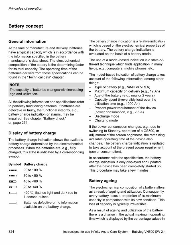
Principles of operation
324 Instructions for use Infinity Acute Care System – Babylog VN500 SW 2.n
Battery concept
General information
At the time of manufacture and delivery, batteries have a typical capacity which is in accordance with the information specified in the battery manufacturer's data sheet. The electrochemical composition of the battery is the determining factor for its total capacity. The operating time of the batteries derived from these specifications can be found in the "Technical data" chapter.
All the following information and specifications refer to perfectly functioning batteries. If batteries are defective or faulty, the functional integrity, e.g., battery charge indication or alarms, may be impaired. See chapter "Battery check" on page 254.
Display of battery charge
The battery charge indication shows the available battery charge determined by the electrochemical processes. When the batteries are, e.g., fully charged, this state is indicated by a corresponding symbol.
The battery charge indication is a relative indication which is based on the electrochemical properties of the battery. The battery charge indication is evaluated on the basis of a battery model.
The use of a model-based indication is a state-of-the-art technique which finds application in many fields, e.g., computers, mobile phones, etc.
The model-based indication of battery charge takes account of the following information, among other things:– Type of battery (e.g., NiMH or VRLA)– Maximum capacity on delivery (e.g., 12 Ah)– Age of the battery (e.g., new or 2 years)– Capacity spent (irreversibly lost) over the
utilization time (e.g., 1000 Ah)– Present power requirement of the device
(power consumption, e.g., 2.5 A)– Discharge mode– Charging mode
If the power consumption changes, e.g., due to switching to Standby, operation of a GS500, or adjustment of the screen brightness, the remaining available operating time of the device also changes. The battery charge indication is updated to take account of the present power requirement (power consumption).
In accordance with the specification, the battery charge indication is only displayed and updated after the device has been completely started up. This procedure may take a few minutes.
Battery ageing
The electrochemical composition of a battery alters as a result of ageing and utilization. Consequently, every battery loses a proportion of its maximum capacity in comparison with its new condition. This loss of capacity is typically irreversible.
As a result of ageing and utilization of the battery, there is a change in the actual maximum operating time which is displayed by the percentage values in
NOTE
The capacity of batteries changes with increasing age and utilization.
Symbol Battery charge
90 to 100 %
60 to <90 %
40 to <60 %
20 to <40 %
<20 %, flashes light and dark red in 1-second pulses.
Batteries defective or no information available on the battery charge.
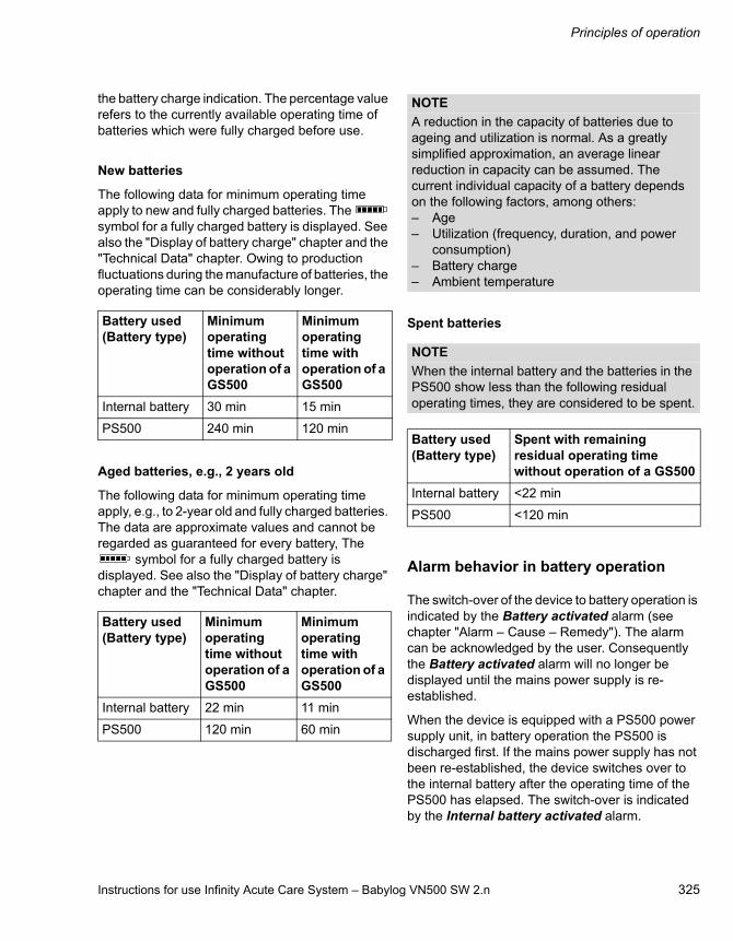
Instructions for use Infinity Acute Care System – Babylog VN500 SW 2.n 325
Principles of operation
the battery charge indication. The percentage value refers to the currently available operating time of batteries which were fully charged before use.
New batteries
The following data for minimum operating time apply to new and fully charged batteries. The symbol for a fully charged battery is displayed. See also the "Display of battery charge" chapter and the "Technical Data" chapter. Owing to production fluctuations during the manufacture of batteries, the operating time can be considerably longer.
Aged batteries, e.g., 2 years old
The following data for minimum operating time apply, e.g., to 2-year old and fully charged batteries. The data are approximate values and cannot be regarded as guaranteed for every battery, The
symbol for a fully charged battery is displayed. See also the "Display of battery charge" chapter and the "Technical Data" chapter.
Spent batteries
Alarm behavior in battery operation
The switch-over of the device to battery operation is indicated by the Battery activated alarm (see chapter "Alarm – Cause – Remedy"). The alarm can be acknowledged by the user. Consequently the Battery activated alarm will no longer be displayed until the mains power supply is re-established.
When the device is equipped with a PS500 power supply unit, in battery operation the PS500 is discharged first. If the mains power supply has not been re-established, the device switches over to the internal battery after the operating time of the PS500 has elapsed. The switch-over is indicated by the Internal battery activated alarm.
Battery used(Battery type)
Minimum operating time without operation of a GS500
Minimum operating time with operation of a GS500
Internal battery 30 min 15 min
PS500 240 min 120 min
Battery used(Battery type)
Minimum operating time without operation of a GS500
Minimum operating time with operation of a GS500
Internal battery 22 min 11 min
PS500 120 min 60 min
NOTE
A reduction in the capacity of batteries due to ageing and utilization is normal. As a greatly simplified approximation, an average linear reduction in capacity can be assumed. The current individual capacity of a battery depends on the following factors, among others:– Age– Utilization (frequency, duration, and power
consumption)– Battery charge– Ambient temperature
NOTE
When the internal battery and the batteries in the PS500 show less than the following residual operating times, they are considered to be spent.
Battery used(Battery type)
Spent with remaining residual operating timewithout operation of a GS500
Internal battery <22 min
PS500 <120 min

Principles of operation
326 Instructions for use Infinity Acute Care System – Babylog VN500 SW 2.n
At the end of the operating time of the internal battery, the device generates the Battery low alarm. The Battery discharged alarm follows after that.
These alarms appear at the time specified by the model-based calculation for the particular battery.
Schematic representation of the sequence of alarms
The schematic representation of the sequence of alarms with respect to battery utilization is shown in an example with a PS500 but without the use of a GS500. The representation corresponds to the operating time of new and fully charged batteries.
When the voltage drop of the internal battery reaches an operationally critical value, a shut-down of the device due to an inadequate supply is immediately imminent. In this case the power supply failure alarm sounds.
37
4
60 120 180 240 0 100 25205 15
PS500 operating time Operating time of the internal battery
PS500 Internal battery
Device shuts down
Battery discharged
Battery low
Internal battery activated
Battery activated
Time [min]
Vol
tage
[V]
Switch-off voltage
NOTE
If the device displays the Battery low alarm message or the Battery discharged alarm message, connect the device to the mains power supply.
NOTE
When the remaining calculated operating time is less than 10 minutes, the model-based Battery low alarm appears. When the remaining calculated operating time is less than 5 minutes, the model-based Battery discharged alarm appears.
Instructions for use Infinity Acute Care System – Babylog VN500 SW 2.n 327
Principles of operation
NOTE
The operating time remaining after the corresponding alarms can be considerably longer than the specified minimum operating time.
NOTE
When the device is fitted with the GS500 gas supply unit, the device calculates the time for the Battery discharged alarm allowing for the power consumption of a GS500, regardless of whether the GS500 is activated or not.

Principles of operation
328 Instructions for use Infinity Acute Care System – Babylog VN500 SW 2.n
Pneumatic functional description
Pneumatic circuit diagram of Babylog VN500
1 Air gas inlet
2 O2 gas inlet
3 Air non-return valve
4 O2 non-return valve
5 Air metering valve
6 O2 metering valve
7 Tank
8 Mixed gas metering valve
9 Safety valve
10 Emergency expiratory valve
11 Emergency breathing valve
12 Patient's lungs
13 Expiratory valve
14 Non-return valve
15 Neonatal flow sensor
16 Barometric pressure sensor
17 Calibration valve for inspiratory pressure sensor
18 Inspiratory pressure sensor
19 Calibration valve for expiratory pressure sensor
20 Expiratory pressure sensor
21 O2 sensor
22 Nebulizer outlet
23 Air pressure regulator
24 O2 pressure regulator
25 Nebulizer mixer valve
26 Nebulizer changeover valve
27 Ejector changeover valve
28 Ejector
29 Muffler
30 CO2 sensor
19
8_
VN
50
0
Ep
Ep
Ep
Ep
EO 2
EO 2
Ep
Ep21
17
19
18
20
9
7
4
3 5
6
8
14
13
15
25
23 24
12
10 11
1
2
1622
BA
C
D
G
EH
F
I
EC O 2
EC O 2
30
EV
EV
27
26
28
29
AirO2
Insp. GasExsp. GasNebulizer gas

Instructions for use Infinity Acute Care System – Babylog VN500 SW 2.n 329
Principles of operation
A Gas mixture and gas metering assembly
B Inspiratory unit assembly
C Expiratory unit assembly
D Muffler
E Barometric pressure sensor
F Pressure measurement assembly
G Calibration assembly
H O2 sensor
I Medication nebulization assembly/Ejector drive
Description of the pneumatic mode of operation
Babylog VN500 consists of 9 pneumatic assemblies.
The gas mixture and dosage assembly (A) delivers the time-variable flow of a gas mixture with adjustable proportions of O2 and air. Gas from the (central) gas supply system enters the device via the gas inlet connections for O2 and air (1, 2). Two non-return valves (3, 4) prevent one gas from returning to the supply line of the other gas. The mixing of the gases takes place in the tank (7) and is controlled via two control valves (5, 6). The supplied inspiratory flow is controlled via a third control valve (8).
The inspiratory unit assembly (B) consists of the safety valve (9) and two non-return valves (10, 11). In normal operation, the safety valve is closed so that the inspiratory flow is supplied to the patient (12) from the gas mixture and gas metering assembly. During other operating states, e.g., when Babylog VN500 is in standby, the safety valve is open and enables spontaneous inspiration through the emergency breathing valve (11). The emergency expiratory valve (10) provides a second channel for expiration when the expiratory valve (13) is blocked.
The expiratory valve assembly (C) consists of the expiratory valve (13) and a non-return valve (14). The expiratory valve is a proportional valve and is used to adjust the pressure in the breathing system. In conjunction with the spring-loaded valve of the emergency air outlet (10), the non-return
valve (14) prevents pendulum breathing during spontaneous breathing. The neonatal flow sensor (15) measures the inspiratory flow and expiratory flow in accordance with the hot-wire anemometry measurement principle. Therefore the measured flow is a mass flow (NTPD).
The ejector (28) generates the negative pressure required for the HFO mode. For this purpose, the ejector valve (27) supplies the driving gas (medication nebulization assembly/ejector drive (I)).
To reduce disruptive noises, the flow is passed behind the expiratory valve (13) via the muffler (D, 29) into the surrounding area.
The inspiratory unit, the expiratory valve, and the muffler assemblies can be detached from Babylog VN500 for cleaning purposes.
The mass flow to volume flow conversion (BTPS) requires knowledge of the ambient pressure. The ambient pressure is measured with the barometric pressure sensor (E, 16).
The pressure in the breathing system is measured with two independent pressure sensors (18, 20) that form the pressure measurement assembly (F). The pressure sensors are regularly zero calibrated. For this, the pressure sensors are connected to ambient pressure via the two calibration valves (17, 19). The calibration valves form the calibration assembly (G).
The O2 sensor (H, 21) measures the inspiratory O2 concentration based on a sidestream measurement principle. For calibration by the user during the device check, the O2 sensor can be flushed with pure O2 from the tank (7).
Principles of operation
330 Instructions for use Infinity Acute Care System – Babylog VN500 SW 2.n
A pneumatic medication nebulizer can be connected to the nebulizer gas outlet (22) for medication nebulization. Babylog VN500 provides an intermittent gas flow consisting of O2 and air to drive the medication nebulizer. This ensures that the deviation of the set O2 concentration remains within the specified limits. For this, the gas from the two gas inlet connections (1, 2) is throttled by the pressure regulators (23, 24). The intermittent gas delivery is done by nebulizer mixer valve (25). The nebulizer changeover valve (26) closes the nebulizer gas outlet when the nebulizer function is not switched on.
The nebulizer mixer valve, the nebulizer changeover valve, the ejector changeover valve, the nebulizer outlet and the two pressure regulators form the medication nebulization/ejector drive assembly (I).
The CO2 concentration of the breathing gas can be measured using the CO2 sensor (30). CO2 is measured according to an optical measurement principle in the mainstream.
An active breathing gas humidifier and a pneumatic medication nebulizer can also be connected. Additional information can be found in the chapters "Assembly and preparation" and "Operation".

Instructions for use Infinity Acute Care System – Babylog VN500 SW 2.n 331
Principles of operation
Main menu bar structure
The following table lists the buttons of the main menu bar with the resulting dialog windows of the same name and the tabs. Touching a tab opens the corresponding page. The dark gray buttons are always contained in the main menu bar. The white
buttons are freely configurable and are assigned to the respective group. The freely configurable buttons open the corresponding page in the dialog window or activate a function.
Group symbol
Button in main menu bar
Horizontal tab Vertical tab Additional tabs
Alarms... Limits
Current alarms
Alarm history
Settings
Alarm volume
Ventilation settings... Modes 1, 2, 3, 4
General settings
Additional settings
Overview
Apnea Ventilation
Trigger
Sigh
Volume Guarantee
ATC
Auto Release
Mode 5 (e.g. PC-HFO)
General settings
Additional settings
Overview
Volume Guarantee (HFO)
HFO-Sigh
Other modes
Trigger
Apnea Ventilation continued next page
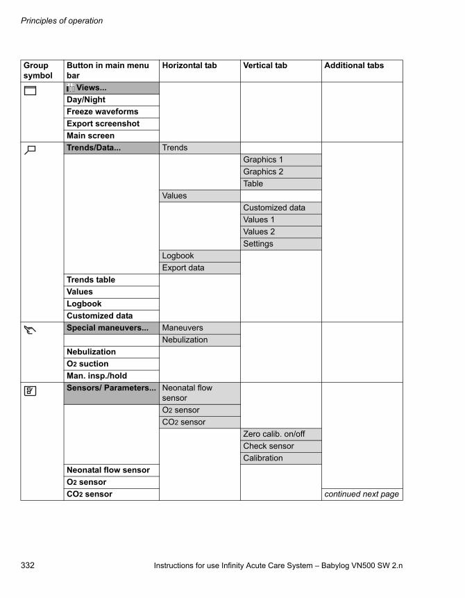
Principles of operation
332 Instructions for use Infinity Acute Care System – Babylog VN500 SW 2.n
Views...
Day/Night
Freeze waveforms
Export screenshot
Main screen
Trends/Data... Trends
Graphics 1
Graphics 2
Table
Values
Customized data
Values 1
Values 2
Settings
Logbook
Export data
Trends table
Values
Logbook
Customized data
Special maneuvers... Maneuvers
Nebulization
Nebulization
O2 suction
Man. insp./hold
Sensors/ Parameters... Neonatal flow sensor
O2 sensor
CO2 sensor
Zero calib. on/off
Check sensor
Calibration
Neonatal flow sensor
O2 sensor
CO2 sensor continued next page
Group symbol
Button in main menu bar
Horizontal tab Vertical tab Additional tabs
1 2 3
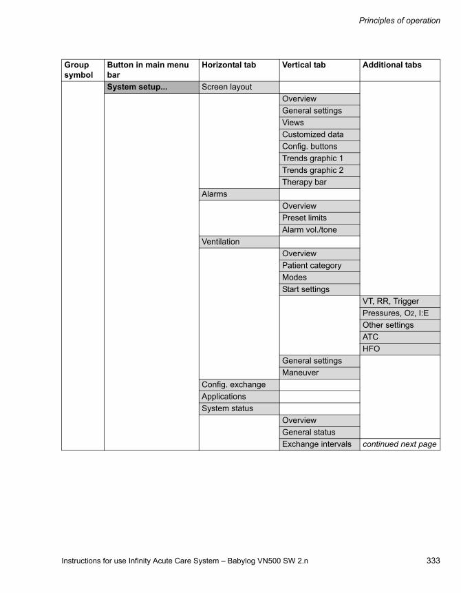
Instructions for use Infinity Acute Care System – Babylog VN500 SW 2.n 333
Principles of operation
System setup... Screen layout
Overview
General settings
Views
Customized data
Config. buttons
Trends graphic 1
Trends graphic 2
Therapy bar
Alarms
Overview
Preset limits
Alarm vol./tone
Ventilation
Overview
Patient category
Modes
Start settings
VT, RR, Trigger
Pressures, O2, I:E
Other settings
ATC
HFO
General settings
Maneuver
Config. exchange
Applications
System status
Overview
General status
Exchange intervals continued next page
Group symbol
Button in main menu bar
Horizontal tab Vertical tab Additional tabs

Principles of operation
334 Instructions for use Infinity Acute Care System – Babylog VN500 SW 2.n
System
Overview
Country
Units
Interface
LAN
COM
External display
Supply units
Service
System Information
Operating Data
Options
Service Call
Applications
Help...
Start/ Standby...
Start/Standby
Tube/NIV
Br. circuit/ Humidifier
System check Overview
Device check
Breathing circ. check
Check results
Battery check
Accessory status
Group symbol
Button in main menu bar
Horizontal tab Vertical tab Additional tabs

Instructions for use Infinity Acute Care System – Babylog VN500 SW 2.n 335
Principles of operation
Factory-set screen views
08
8_
VN
50
0
View 1
View 2
View 3
Waveform Paw
Waveform Flow
FiO2
Pmean
MVe
RR
Waveform Paw
Waveform Flow
Waveform Volume
FiO2
Pmean
MVe
VT
Cdyn
R
Waveform Paw
Loop Pressure Volume
Cdyn
C20/Cdyn
TC
% leak
R

Principles of operation
336 Instructions for use Infinity Acute Care System – Babylog VN500 SW 2.n
List of references
[1] Meyer, J.: Neue Beatmungsformen.Anästhesiol. Intensivmed. Notfallmed. Schmerzther. [New Ventilation Modes. Anesthesiology. Intensive-Care Medicine. Emergency Medicine. Pain Therapy.] 26 (1991) 337-342
[2] Vincent, J.-L.: Yearbook of Intensive Care and Emergency Medicine.Springer-Verlag, 1993
[3] Stock, M. C., Downs, J. B., Frolicher, D.: Airway Pressure Release Ventilation.Critical Care Medicine 15 (1987): 462-466
[4] Räsänen, J., Cane, R. D., Downs, J. B., et al.: Airway Pressure Release Ventilation During Acute Lung Injury: A Prospective Multicenter Trial.Critical Care Medicine 19 (1991): 1234-1241
[5] Guttmann, W., Eberhard, L., Fabry, B., et al.: Continuous Calculation of Tracheal Pressure in Tracheally Intubated Patients.Anesthesiology 79 (1993): 503-513

Instructions for use Infinity Acute Care System – Babylog VN500 SW 2.n 337
Index
Index
A
Abbreviations . . . . . . . . . . . . . . . . . . . . . . . . . . . 27Accessories . . . . . . . . . . . . . . . . . . . . . . . . . . . . . 8
Attaching. . . . . . . . . . . . . . . . . . . . . . . . . . . . 26Accessories, displaying the status of . . . . . . . . . 81Acoustic alarm, failure . . . . . . . . . . . . . . . . . . . 132Additional buttons. . . . . . . . . . . . . . . . . . . . . . . 161Additional settings for ventilation . . . . . . . . . . . . 89
Description . . . . . . . . . . . . . . . . . . . . . . . . . 304Start-up settings . . . . . . . . . . . . . . . . . . . . . 174Ventilation parameters . . . . . . . . . . . . . . . . . 90
Aeroneb nebulizer . . . . . . . . . . . . . . . . . . . . . . 109Alarm history. . . . . . . . . . . . . . . . . . . . . . . . . . . 127Alarm limits
Automatic setting . . . . . . . . . . . . . . . . . . . . 282Configuring start-up values. . . . . . . . . . . . . 165Deactivating . . . . . . . . . . . . . . . . . . . . . . . . 128In event of power failure . . . . . . . . . . . . . . . 129Setting. . . . . . . . . . . . . . . . . . . . . . . . . . . . . 128Table. . . . . . . . . . . . . . . . . . . . . . . . . . . . . . 166
Alarm priorities . . . . . . . . . . . . . . . . . . . . . . . . . 125Alarm tone
Setting the volume . . . . . . . . . . . . . . . . . . . 130Suppressing . . . . . . . . . . . . . . . . . . . . . . . . 131
Alarm-Cause-Remedy . . . . . . . . . . . . . . . . . . . 189Alarms
Acknowledging . . . . . . . . . . . . . . . . . . . . . . 126Current alarms . . . . . . . . . . . . . . . . . . . . . . 126Displaying causes and remedies . . . . . . . . 126
Ambient air filter, replacing. . . . . . . . . . . . . . . . 251Anti Air Shower
Switch on or off . . . . . . . . . . . . . . . . . . . . . . 177Apnea ventilation
Auto. Return, switching on or off. . . . . . . . . 177Description . . . . . . . . . . . . . . . . . . . . . . . . . 304Switch alarm on or off . . . . . . . . . . . . . . . . . 177Switch on or off . . . . . . . . . . . . . . . . . . . . . . 174
Application modeNIV . . . . . . . . . . . . . . . . . . . . . . . . . . . . . . . . 93Selecting . . . . . . . . . . . . . . . . . . . . . . . . . . . . 78Tube . . . . . . . . . . . . . . . . . . . . . . . . . . . . . . . 78
Assembly . . . . . . . . . . . . . . . . . . . . . . . . . . . . . 244ATC
Description . . . . . . . . . . . . . . . . . . . . . . . . . 312Switch on or off . . . . . . . . . . . . . . . . . . . . . . 175
Automatic alarm limits . . . . . . . . . . . . . . . . . . . 282Automatic leakage compensation. . . . . . . . . . . 320AutoRelease, description . . . . . . . . . . . . . . . . . 315
B
Bacterial filter. . . . . . . . . . . . . . . . . . . . . . . . . . . 52Battery
Disposal . . . . . . . . . . . . . . . . . . . . . . . . . . . 259Internal. . . . . . . . . . . . . . . . . . . . . . . . . . . . 118
Battery charging . . . . . . . . . . . . . . . . . . . . . . . 119Battery maintenance . . . . . . . . . . . . . . . . . . . . 254Battery operation . . . . . . . . . . . . . . . . . . . . . . . 119Before reuse . . . . . . . . . . . . . . . . . . . . . . . . . . 245Body height/body weight . . . . . . . . . . . . . . . . . . 66Breathing circuit
Check. . . . . . . . . . . . . . . . . . . . . . . . . . . . . . 74Connecting. . . . . . . . . . . . . . . . . . . . . . . . . . 54Disconnecting . . . . . . . . . . . . . . . . . . . . . . 230Safety information . . . . . . . . . . . . . . . . . . . . 52Selecting . . . . . . . . . . . . . . . . . . . . . . . . . . . 68Setting . . . . . . . . . . . . . . . . . . . . . . . . . . . . . 55User-defined . . . . . . . . . . . . . . . . . . . . . . . . 68
Breathing gas humidifierAttaching . . . . . . . . . . . . . . . . . . . . . . . . . . . 53Selecting . . . . . . . . . . . . . . . . . . . . . . . . . . . 68
Brightness, adjusting . . . . . . . . . . . . . . . . . . . . 157BTPS . . . . . . . . . . . . . . . . . . . . . . . . . . . . . . . . 323
C
C20/C, description. . . . . . . . . . . . . . . . . . . . . . 317Calibrating the O2 sensor . . . . . . . . . . . . . . . . 146Checking readiness for operation . . . . . . . . . . . 70CO2 cuvette, installing. . . . . . . . . . . . . . . . . . . . 57CO2 monitoring . . . . . . . . . . . . . . . . . . . . . . . . 147
Deactivating or activating. . . . . . . . . . . . . . 153CO2 sensor
Check calibration with test filter . . . . . . . . . 150Check calibration with test gas . . . . . . . . . 151Dismantling . . . . . . . . . . . . . . . . . . . . . . . . 231Installing. . . . . . . . . . . . . . . . . . . . . . . . . . . . 57Performing calibration . . . . . . . . . . . . . . . . 152
CO2 zero calibration . . . . . . . . . . . . . . . . . . . . 149CO2 zero indication . . . . . . . . . . . . . . . . . . . . . 149Compressed gas cylinders . . . . . . . . . . . . . . . . 44Configuration . . . . . . . . . . . . . . . . . . . . . . . . . . 155Configuring alarm settings. . . . . . . . . . . . . . . . 165Configuring units . . . . . . . . . . . . . . . . . . . . . . . 184Connecting the nurse call . . . . . . . . . . . . . . . . . 61Connection with other electrical equipment. . . . . 9Contraindications. . . . . . . . . . . . . . . . . . . . . . . . 18Country-specific settings . . . . . . . . . . . . . . . . . 183

Index
338 Instructions for use Infinity Acute Care System – Babylog VN500 SW 2.n
Curve fields, selecting the display . . . . . . . . . . . 96Curves and measured values, displaying. . . . . . 95Cuvette type, selecting . . . . . . . . . . . . . . . . . . . 147
D
Data export . . . . . . . . . . . . . . . . . . . . . . . . . . . . 140Data transfer. . . . . . . . . . . . . . . . . . . . . . . . . . . . 26Date and time . . . . . . . . . . . . . . . . . . . . . . . . . . 183DC power supply . . . . . . . . . . . . . . . . . . . . . . . 118Definitions. . . . . . . . . . . . . . . . . . . . . . . . . . . . . . . 3Description . . . . . . . . . . . . . . . . . . . . . . . . . . . . 289Device check . . . . . . . . . . . . . . . . . . . . . . . . . . . 71Dialogs windows. . . . . . . . . . . . . . . . . . . . . . . . . 38Disassembly . . . . . . . . . . . . . . . . . . . . . . . . . . . 230Disinfection. . . . . . . . . . . . . . . . . . . . . . . . . . . . 229Display data . . . . . . . . . . . . . . . . . . . . . . . . . . . 138Displaying data
All measurements . . . . . . . . . . . . . . . . . . . . 138Hospital-specific data . . . . . . . . . . . . . . . . . 138Set values . . . . . . . . . . . . . . . . . . . . . . . . . . 138
Disposable cuvettes . . . . . . . . . . . . . . . . . . . . . 147Disposal . . . . . . . . . . . . . . . . . . . . . . . . . . . . . . 257Disposal of the device . . . . . . . . . . . . . . . . . . . 259
E
Electrical supplyFailure. . . . . . . . . . . . . . . . . . . . . . . . . . . . . . 59Internal battery . . . . . . . . . . . . . . . . . . . . . . . 59Mains power supply . . . . . . . . . . . . . . . . . . . 58
Environment of use . . . . . . . . . . . . . . . . . . . . . . 18Exchange intervals . . . . . . . . . . . . . . . . . . . . . . 182Expiratory compensation, switching on or off . . 175Expiratory valve
Dismantling . . . . . . . . . . . . . . . . . . . . . . . . . 230Inserting . . . . . . . . . . . . . . . . . . . . . . . . . . . . 51Preparing . . . . . . . . . . . . . . . . . . . . . . . . . . . 50Replace diaphragm. . . . . . . . . . . . . . . . . . . 251
External screen . . . . . . . . . . . . . . . . . . . . . . . . 186
F
Factory settings . . . . . . . . . . . . . . . . . . . . . . . . 172Fisher & Paykel MR 850. . . . . . . . . . . . . . . . . . . 53Flow monitoring . . . . . . . . . . . . . . . . . . . . . . . . 143
Deactivating or activating . . . . . . . . . . . . . . 145Flow reduction . . . . . . . . . . . . . . . . . . . . . . . . . 321Flow trigger, description . . . . . . . . . . . . . . . . . . 306Format templates . . . . . . . . . . . . . . . . . . . . . . . 158Freezing waveforms . . . . . . . . . . . . . . . . . . . . . . 97Front panel . . . . . . . . . . . . . . . . . . . . . . . . . . . . . 21Fuse . . . . . . . . . . . . . . . . . . . . . . . . . . . . . . . . . . 22
G
Gas supply . . . . . . . . . . . . . . . . . . . . . . . . . . . . 26Central gas supply. . . . . . . . . . . . . . . . . . . . 60Connecting . . . . . . . . . . . . . . . . . . . . . . . . . 60From cylinders . . . . . . . . . . . . . . . . . . . . . . . 60
General settings for ventilation . . . . . . . . . . . . . 86Getting started. . . . . . . . . . . . . . . . . . . . . . . . . . 63
Safety information . . . . . . . . . . . . . . . . . . . . 64Graphic trends. . . . . . . . . . . . . . . . . . . . . . . . . 134GS500 gas supply unit . . . . . . . . . . . . . . . . . . 110
Connecting the mains power supply . . . . . . 59Functionality . . . . . . . . . . . . . . . . . . . . . . . 186
H
Header bar . . . . . . . . . . . . . . . . . . . . . . . . . . . . 36Height above sea level . . . . . . . . . . . . . . . . . . 184Help . . . . . . . . . . . . . . . . . . . . . . . . . . . . . . . . . . 99HFO sigh, description . . . . . . . . . . . . . . . . . . . 309HME . . . . . . . . . . . . . . . . . . . . . . . . . . . . . . . . . 52Hospital-specific measured values . . . . . . . . . 160Humidifier holder . . . . . . . . . . . . . . . . . . . . . . . . 43
I
Illumination adjusting. . . . . . . . . . . . . . . . . . . . 157Import/export of configurations . . . . . . . . . . . . 178Indications . . . . . . . . . . . . . . . . . . . . . . . . . . . . . 18Infinity Acute Care System, system overview . . . . . . . . . . . . . . . . . . . . . . . . . . . . . . 20Infinity C500
Positioning . . . . . . . . . . . . . . . . . . . . . . . . . . 46Preparing . . . . . . . . . . . . . . . . . . . . . . . . . . . 46
Infinity ID breathing circuit . . . . . . . . . . . . . . 54, 69Infinity ID components. . . . . . . . . . . . . . . . . . . . 15Inspection . . . . . . . . . . . . . . . . . . . . . . . . . . . . . . 8Inspiratory hold . . . . . . . . . . . . . . . . . . . . . . . . 100Inspiratory termination
Criterion . . . . . . . . . . . . . . . . . . . . . . . . . . . 307Description. . . . . . . . . . . . . . . . . . . . . . . . . 307
Installing applications . . . . . . . . . . . . . . . . . . . 180Instructions for use, observing . . . . . . . . . . . . . . 8Intended use . . . . . . . . . . . . . . . . . . . . . . . . . . . 18Interfaces, configuring . . . . . . . . . . . . . . . . . . . 185Intrahospital patient transport . . . . . . . . . . . . . 121

Instructions for use Infinity Acute Care System – Babylog VN500 SW 2.n 339
Index
L
LAN. . . . . . . . . . . . . . . . . . . . . . . . . . . . . . . . . . 185Lateral flaps on the device . . . . . . . . . . . . . . . . . 62Leakage compensation
Description . . . . . . . . . . . . . . . . . . . . . . . . . 320Switch on or off . . . . . . . . . . . . . . . . . . . . . . 177
Leakage rate. . . . . . . . . . . . . . . . . . . . . . . . . . . 320List of references . . . . . . . . . . . . . . . . . . . . . . . 336Logbook, displaying . . . . . . . . . . . . . . . . . . . . . 139Loops
Evaluating . . . . . . . . . . . . . . . . . . . . . . . . . . . 97Reference loop . . . . . . . . . . . . . . . . . . . . . . . 97
M
Main menu bar . . . . . . . . . . . . . . . . . . . . . . . . . . 37Structure . . . . . . . . . . . . . . . . . . . . . . . . . . . 331
Main screen . . . . . . . . . . . . . . . . . . . . . . . . . . . . 36Mains power supply . . . . . . . . . . . . . . . . . . . . . 118Maintenance. . . . . . . . . . . . . . . . . . . . . . . . . . . . . 8Maneuvers . . . . . . . . . . . . . . . . . . . . . . . . . . . . 100Manual inspiration . . . . . . . . . . . . . . . . . . . . . . 100Manual ventilation device . . . . . . . . . . . . . . . . . . 14Measurement principles . . . . . . . . . . . . . . . . . . 322MEDIBUS . . . . . . . . . . . . . . . . . . . . . . . . . . . . . . 48Medication nebulization
Applying . . . . . . . . . . . . . . . . . . . . . . . . . . . 103Description . . . . . . . . . . . . . . . . . . . . . . . . . 316Switching on . . . . . . . . . . . . . . . . . . . . . . . . 106
Medication nebulizer. . . . . . . . . . . . . . . . . . . . . . 26Dismantling . . . . . . . . . . . . . . . . . . . . . . . . . 232Installing . . . . . . . . . . . . . . . . . . . . . . . . . . . 104Preparing . . . . . . . . . . . . . . . . . . . . . . . . . . 104
Monitoring. . . . . . . . . . . . . . . . . . . . . . . . . . 25, 141Monitoring fields, changing display. . . . . . . . . . . 95Monitoring functions . . . . . . . . . . . . . . . . . . . . . . 25
N
Neonatal flow sensorCalibrating. . . . . . . . . . . . . . . . . . . . . . . . . . 143Dismantling . . . . . . . . . . . . . . . . . . . . . . . . . 230Disposal . . . . . . . . . . . . . . . . . . . . . . . . . . . 259Installing . . . . . . . . . . . . . . . . . . . . . . . . . . . . 55Replacing insert . . . . . . . . . . . . . . . . . . . . . . 56
New patient. . . . . . . . . . . . . . . . . . . . . . . . . . . . . 65Non-invasive ventilation
Applying . . . . . . . . . . . . . . . . . . . . . . . . . . . . 92Description . . . . . . . . . . . . . . . . . . . . . . . . . 319
NTPD . . . . . . . . . . . . . . . . . . . . . . . . . . . . . . . . 323
O
O2 monitoring . . . . . . . . . . . . . . . . . . . . . . . . . 146Deactivating or activating. . . . . . . . . . . . . . 146
O2 therapy . . . . . . . . . . . . . . . . . . . . . . . . . . . . 111Description. . . . . . . . . . . . . . . . . . . . . . . . . 319Setting O2 and flow . . . . . . . . . . . . . . . . . . 113Switching off . . . . . . . . . . . . . . . . . . . . . . . 113Switching on . . . . . . . . . . . . . . . . . . . . . . . 112
Operating concept . . . . . . . . . . . . . . . . . . . . . . . 36Operation. . . . . . . . . . . . . . . . . . . . . . . . . . . . . . 83Operation display of ventilation . . . . . . . . . . . . . 21Oxygen enrichment for suction maneuver. . . . 101
P
Parameter fields, selecting the display . . . . . . . 96Password. . . . . . . . . . . . . . . . . . . . . . . . . 156, 341Patient category . . . . . . . . . . . . . . . . . . . . . . . . 66Patient monitoring . . . . . . . . . . . . . . . . . . . . 10, 14Patient safety. . . . . . . . . . . . . . . . . . . . . . . . . . . 10Patient transport . . . . . . . . . . . . . . . . . . . . . . . 121Patient, selecting a . . . . . . . . . . . . . . . . . . . . . . 65Pmax/Paw high AutoSet
Switch on or off . . . . . . . . . . . . . . . . . . . . . 177Pneumatic functional description. . . . . . . . . . . 328Pneumatic medication nebulizer . . . . . . . . . . . 104Power failure alarm . . . . . . . . . . . . . . . . . . . . . . 59Power on . . . . . . . . . . . . . . . . . . . . . . . . . . . . . . 64Power supply. . . . . . . . . . . . . . . . . . . . . . . . . . . 26Power supply unit PS500 . . . . . . . . . . . . . . . . 118Preparing the ventilation unit. . . . . . . . . . . . . . . 50Pressure-controlled ventilation modes . . . . . . . 87Previous patient. . . . . . . . . . . . . . . . . . . . . . . . . 65
R
Range of functions . . . . . . . . . . . . . . . . . . . . . . 25Rear view . . . . . . . . . . . . . . . . . . . . . . . . . . . . . 22Repair . . . . . . . . . . . . . . . . . . . . . . . . . . . . . . . . . 8Reprocessing . . . . . . . . . . . . . . . . . . . . . . . . . 229Reprocessing list . . . . . . . . . . . . . . . . . . . . . . . 236Reusable cuvettes. . . . . . . . . . . . . . . . . . . . . . 147
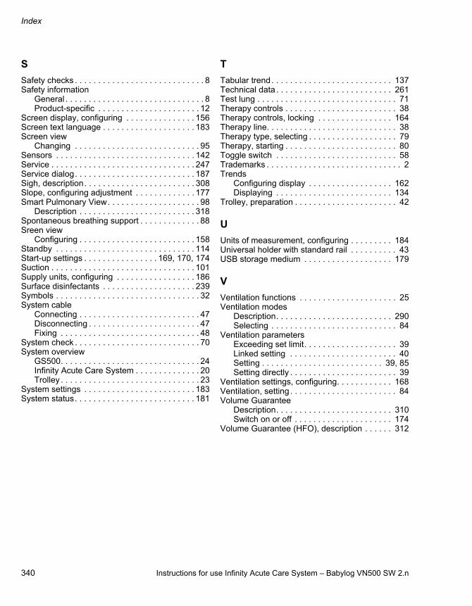
Index
340 Instructions for use Infinity Acute Care System – Babylog VN500 SW 2.n
S
Safety checks . . . . . . . . . . . . . . . . . . . . . . . . . . . . 8Safety information
General . . . . . . . . . . . . . . . . . . . . . . . . . . . . . . 8Product-specific . . . . . . . . . . . . . . . . . . . . . . 12
Screen display, configuring . . . . . . . . . . . . . . . 156Screen text language . . . . . . . . . . . . . . . . . . . . 183Screen view
Changing . . . . . . . . . . . . . . . . . . . . . . . . . . . 95Sensors . . . . . . . . . . . . . . . . . . . . . . . . . . . . . . 142Service . . . . . . . . . . . . . . . . . . . . . . . . . . . . . . . 247Service dialog. . . . . . . . . . . . . . . . . . . . . . . . . . 187Sigh, description. . . . . . . . . . . . . . . . . . . . . . . . 308Slope, configuring adjustment . . . . . . . . . . . . . 177Smart Pulmonary View. . . . . . . . . . . . . . . . . . . . 98
Description . . . . . . . . . . . . . . . . . . . . . . . . . 318Spontaneous breathing support . . . . . . . . . . . . . 88Sreen view
Configuring . . . . . . . . . . . . . . . . . . . . . . . . . 158Standby . . . . . . . . . . . . . . . . . . . . . . . . . . . . . . 114Start-up settings . . . . . . . . . . . . . . . . 169, 170, 174Suction . . . . . . . . . . . . . . . . . . . . . . . . . . . . . . . 101Supply units, configuring . . . . . . . . . . . . . . . . . 186Surface disinfectants . . . . . . . . . . . . . . . . . . . . 239Symbols . . . . . . . . . . . . . . . . . . . . . . . . . . . . . . . 32System cable
Connecting . . . . . . . . . . . . . . . . . . . . . . . . . . 47Disconnecting . . . . . . . . . . . . . . . . . . . . . . . . 47Fixing . . . . . . . . . . . . . . . . . . . . . . . . . . . . . . 48
System check . . . . . . . . . . . . . . . . . . . . . . . . . . . 70System overview
GS500. . . . . . . . . . . . . . . . . . . . . . . . . . . . . . 24Infinity Acute Care System . . . . . . . . . . . . . . 20Trolley . . . . . . . . . . . . . . . . . . . . . . . . . . . . . . 23
System settings . . . . . . . . . . . . . . . . . . . . . . . . 183System status. . . . . . . . . . . . . . . . . . . . . . . . . . 181
T
Tabular trend. . . . . . . . . . . . . . . . . . . . . . . . . . 137Technical data . . . . . . . . . . . . . . . . . . . . . . . . . 261Test lung . . . . . . . . . . . . . . . . . . . . . . . . . . . . . . 71Therapy controls . . . . . . . . . . . . . . . . . . . . . . . . 38Therapy controls, locking . . . . . . . . . . . . . . . . 164Therapy line. . . . . . . . . . . . . . . . . . . . . . . . . . . . 38Therapy type, selecting . . . . . . . . . . . . . . . . . . . 79Therapy, starting . . . . . . . . . . . . . . . . . . . . . . . . 80Toggle switch . . . . . . . . . . . . . . . . . . . . . . . . . . 58Trademarks . . . . . . . . . . . . . . . . . . . . . . . . . . . . . 2Trends
Configuring display . . . . . . . . . . . . . . . . . . 162Displaying . . . . . . . . . . . . . . . . . . . . . . . . . 134
Trolley, preparation . . . . . . . . . . . . . . . . . . . . . . 42
U
Units of measurement, configuring . . . . . . . . . 184Universal holder with standard rail . . . . . . . . . . 43USB storage medium . . . . . . . . . . . . . . . . . . . 179
V
Ventilation functions . . . . . . . . . . . . . . . . . . . . . 25Ventilation modes
Description. . . . . . . . . . . . . . . . . . . . . . . . . 290Selecting . . . . . . . . . . . . . . . . . . . . . . . . . . . 84
Ventilation parametersExceeding set limit. . . . . . . . . . . . . . . . . . . . 39Linked setting . . . . . . . . . . . . . . . . . . . . . . . 40Setting . . . . . . . . . . . . . . . . . . . . . . . . . . 39, 85Setting directly . . . . . . . . . . . . . . . . . . . . . . . 39
Ventilation settings, configuring. . . . . . . . . . . . 168Ventilation, setting . . . . . . . . . . . . . . . . . . . . . . . 84Volume Guarantee
Description. . . . . . . . . . . . . . . . . . . . . . . . . 310Switch on or off . . . . . . . . . . . . . . . . . . . . . 174
Volume Guarantee (HFO), description . . . . . . 312
Instructions for use Infinity Acute Care System – Babylog VN500 SW 2.n 341
Password for Babylog VN500 SW 2.n
Cut out from the Babylog VN500 instructions for use SW 2.n
To prevent unauthorized adjustments, the following pages are password-protected:– System setup > Screen layout > Views – System setup > Alarms – System setup > Ventilation – System setup > Applications – System setup > Exchange intervals
Information on the password
To prevent unauthorized adjustments, the following pages in the System setup dialog window are password-protected:– Screen layout > Views – Alarms – Ventilation – Applications – Exchange intervals
The password appears on this page of the instructions for use. Cut out the area with the password and keep in a place which is safe from access by unauthorized persons.
If the area with the password has been removed, ask the person responsible for your device about making adjustments to the pages specified.
4572

342 Instructions for use Infinity Acute Care System – Babylog VN500 SW 2.n
This page has been left blank intentionally.

Instructions for use Infinity Acute Care System – Babylog VN500 SW 2.n 343
This page has been left blank intentionally.
These instructions for use only apply to Babylog VN500 SW 2.n with the Serial No.:If no Serial No. has been filled in by Dräger, these instructions for use are provided for general information only and are not intended for use with any specific medical device.These instructions for use are provided for customer information only and will only be updated or exchanged upon customer request.
Directive 93/42/EWGconcerning medical devices
Manufacturer
Drägerwerk AG & Co. KGaA Moislinger Allee 53 – 55D-23542 LübeckGermany+49 451 8 82-0
FAX +49 451 8 82-20 80http://www.draeger.com
9038982 – GA 6500.360 en© Drägerwerk AG & Co. KGaAEdition: 8 – 2016-04(Edition: 1 – 2009-06)Dräger reserves the right to make modifications to the device without prior notice.
Labeling in accordance with Directive 1999/5/EC on radio equipment and telecommunications terminal equipment