Embed Size (px)
Citation preview

Instructions for the 16A2 & 16A3 SeriesMicroprocessor Based
Temperature / Process Control
LOVE CONTROLS DIVISION Phone: 219/879-8000DWYER INSTRUMENTS, INC. www.love-controls.comP.O. BOX 373 • MICHIGAN CITY, INDIANA 46360, U.S.A e-mail: [email protected]
Bulletin 949-1265
949-1265:Layout 1 1/25/11 10:21 AM Page 1
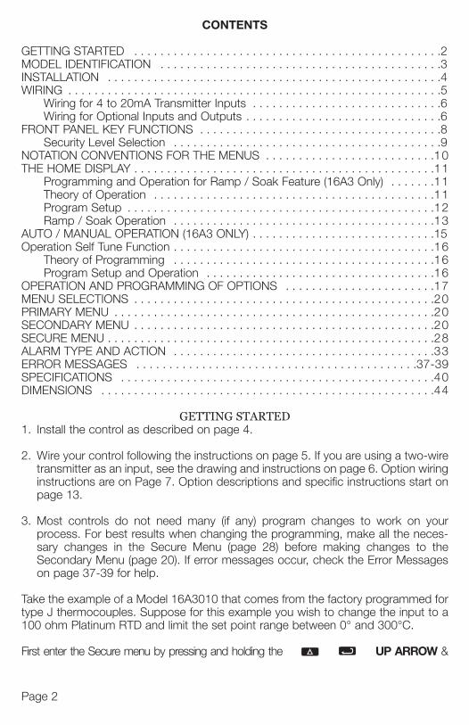
CONTENTS
GETTING STARTED . . . . . . . . . . . . . . . . . . . . . . . . . . . . . . . . . . . . . . . . . . . . . . .2MODEL IDENTIFICATION . . . . . . . . . . . . . . . . . . . . . . . . . . . . . . . . . . . . . . . . . . .3INSTALLATION . . . . . . . . . . . . . . . . . . . . . . . . . . . . . . . . . . . . . . . . . . . . . . . . . . .4WIRING . . . . . . . . . . . . . . . . . . . . . . . . . . . . . . . . . . . . . . . . . . . . . . . . . . . . . . . . .5
Wiring for 4 to 20mA Transmitter Inputs . . . . . . . . . . . . . . . . . . . . . . . . . . . . .6Wiring for Optional Inputs and Outputs . . . . . . . . . . . . . . . . . . . . . . . . . . . . . .6
FRONT PANEL KEY FUNCTIONS . . . . . . . . . . . . . . . . . . . . . . . . . . . . . . . . . . . . .8Security Level Selection . . . . . . . . . . . . . . . . . . . . . . . . . . . . . . . . . . . . . . . . .9
NOTATION CONVENTIONS FOR THE MENUS . . . . . . . . . . . . . . . . . . . . . . . . . .10THE HOME DISPLAY . . . . . . . . . . . . . . . . . . . . . . . . . . . . . . . . . . . . . . . . . . . . . .11
Programming and Operation for Ramp / Soak Feature (16A3 Only) . . . . . . .11Theory of Operation . . . . . . . . . . . . . . . . . . . . . . . . . . . . . . . . . . . . . . . . . . .11Program Setup . . . . . . . . . . . . . . . . . . . . . . . . . . . . . . . . . . . . . . . . . . . . . . .12Ramp / Soak Operation . . . . . . . . . . . . . . . . . . . . . . . . . . . . . . . . . . . . . . . .13
AUTO / MANUAL OPERATION (16A3 ONLY) . . . . . . . . . . . . . . . . . . . . . . . . . . . .15Operation Self Tune Function . . . . . . . . . . . . . . . . . . . . . . . . . . . . . . . . . . . . . . . .16
Theory of Programming . . . . . . . . . . . . . . . . . . . . . . . . . . . . . . . . . . . . . . . .16Program Setup and Operation . . . . . . . . . . . . . . . . . . . . . . . . . . . . . . . . . . .16
OPERATION AND PROGRAMMING OF OPTIONS . . . . . . . . . . . . . . . . . . . . . . .17MENU SELECTIONS . . . . . . . . . . . . . . . . . . . . . . . . . . . . . . . . . . . . . . . . . . . . . .20PRIMARY MENU . . . . . . . . . . . . . . . . . . . . . . . . . . . . . . . . . . . . . . . . . . . . . . . . .20SECONDARY MENU . . . . . . . . . . . . . . . . . . . . . . . . . . . . . . . . . . . . . . . . . . . . . .20SECURE MENU . . . . . . . . . . . . . . . . . . . . . . . . . . . . . . . . . . . . . . . . . . . . . . . . . .28ALARM TYPE AND ACTION . . . . . . . . . . . . . . . . . . . . . . . . . . . . . . . . . . . . . . . .33ERROR MESSAGES . . . . . . . . . . . . . . . . . . . . . . . . . . . . . . . . . . . . . . . . . . .37-39SPECIFICATIONS . . . . . . . . . . . . . . . . . . . . . . . . . . . . . . . . . . . . . . . . . . . . . . . .40DIMENSIONS . . . . . . . . . . . . . . . . . . . . . . . . . . . . . . . . . . . . . . . . . . . . . . . . . . .44
GETTING STARTED1.
2.
3.
Take the example of a Model 16A3010 that comes from the factory programmed fortype J thermocouples. Suppose for this example you wish to change the input to a100 ohm Platinum RTD and limit the set point range between 0° and 300°C.
First enter the Secure menu by pressing and holding the UP ARROW &
ENTplay Don
Nextuntil
Nexttions
Finathe d
The switc
out’
If yothespage
Install the control as described on page 4.
Wire your control following the instructions on page 5. If you are using a two-wiretransmitter as an input, see the drawing and instructions on page 6. Option wiringinstructions are on Page 7. Option descriptions and specific instructions start onpage 13.
Most controls do not need many (if any) program changes to work on yourprocess. For best results when changing the programming, make all the neces-sary changes in the Secure Menu (page 28) before making changes to theSecondary Menu (page 20). If error messages occur, check the Error Messageson page 37-39 for help.
Page 2
Optio
992*993*995*996*9502
* Theoption
Fe2 3
949-1265:Layout 1 1/25/11 10:22 AM Page 2

. .2 . .3 . .4 . .5 . .6 . .6 . .8 . .9 .10 .11 .11 .11 .12 .13 .15 .16 .16 .16 .17 .20 .20 .20 .28 .33
7-39 .40 .44
d forto a
W &
ENTER keys for 5 Seconds (see Page 28.) Press the INDEX key until the dis-play shows 1nP and press the DOWN ARROW until the display shows P385.Don’t forget to press the ENTER key to retain your setting.
Next, press the INDEX key to display Unit. Press the DOWN ARROWuntil the display shows C. Press ENTER.
Next, press the INDEX key until SPL is displayed (pass the dPt and 1nPt selec-tions). Press the UP ARROW until the display shows 0. Press ENTER.
Finally, press INDEX key to display SPH. Press the DOWN ARROW untilthe display shows 300. Press ENTER.
The necessary program changes are now complete. After 30 seconds the display willswitch back to the temperature reading. If you want to return faster, press the
UP ARROW and ENTER keys (at the same time) and then press the DOWN ARROW and INDEX keys (again at the same time). This will ‘back
out’ of the menu and immediately display the temperature reading.
If you want to use Self Tune or Auto/Manual features, see the special sections onthese items. Page numbers for these are in the Contents section on the previouspage.
MODEL IDENTIFICATION
16A — —
Page 3
wirewiringrt on
yources-the
ages
Option Description
992* RS-485 Serial Communications, Lovelink™ protocol.993* RS-232 Serial Communications, Lovelink™ protocol.995* RS-232 Serial Communications, Modbus™ protocol.996* RS-485 Serial Communications, Modbus™ protocol.9502 12-24 Vdc/Vac 50-400 Hz power supply (control operates on low voltage equipment).
* These options may not be combined with each other. Option 9502 may be combined with any otheroptions.
Features2 = Standard3 = Enhanced
Alarm0 = No1 = Yes
Output A1 = SSR2 = 15 VDC3 = Relay, NO4 = Relay, NC5 = Current8 = DC SSR
Output B0 = None1 = SSR2 = 15 VDC3 = Relay, NO4 = Relay, NC5 = Current8 = DC SSR
Options(blank if none)
949-1265:Layout 1 1/25/11 10:22 AM Page 3
Page 4
INSTALLATION
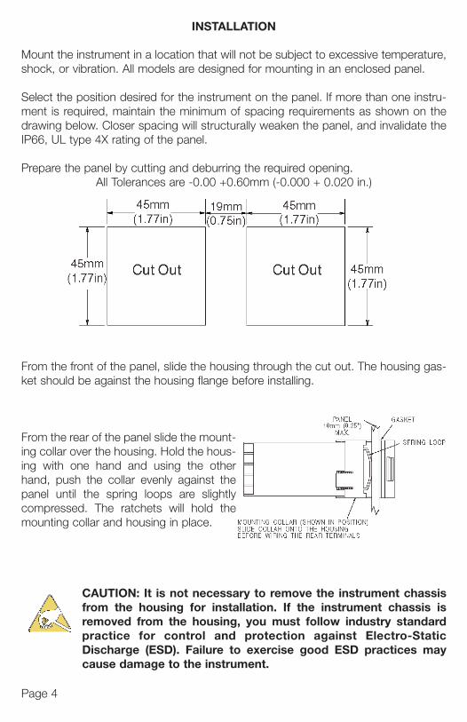
Mount the instrument in a location that will not be subject to excessive temperature,shock, or vibration. All models are designed for mounting in an enclosed panel.
Select the position desired for the instrument on the panel. If more than one instru-ment is required, maintain the minimum of spacing requirements as shown on thedrawing below. Closer spacing will structurally weaken the panel, and invalidate theIP66, UL type 4X rating of the panel.
Prepare the panel by cutting and deburring the required opening.All Tolerances are -0.00 +0.60mm (-0.000 + 0.020 in.)
From the front of the panel, slide the housing through the cut out. The housing gas-ket should be against the housing flange before installing.
From the rear of the panel slide the mount-ing collar over the housing. Hold the hous-ing with one hand and using the otherhand, push the collar evenly against thepanel until the spring loops are slightlycompressed. The ratchets will hold themounting collar and housing in place.
CAUTION: It is not necessary to remove the instrument chassisfrom the housing for installation. If the instrument chassis isremoved from the housing, you must follow industry standardpractice for control and protection against Electro-StaticDischarge (ESD). Failure to exercise good ESD practices maycause damage to the instrument.
For tfor y
For sUse disco
Inpu15 V
Conmina
949-1265:Layout 1 1/25/11 10:22 AM Page 4
Page 5
ture,
stru-n thee the
gas-
ssiss is
dardaticmay
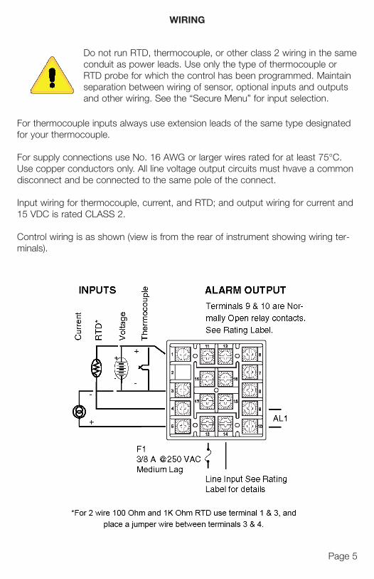
For thermocouple inputs always use extension leads of the same type designatedfor your thermocouple.
For supply connections use No. 16 AWG or larger wires rated for at least 75°C.Use copper conductors only. All line voltage output circuits must hvave a commondisconnect and be connected to the same pole of the connect.
Input wiring for thermocouple, current, and RTD; and output wiring for current and15 VDC is rated CLASS 2.
Control wiring is as shown (view is from the rear of instrument showing wiring ter-minals).
Do not run RTD, thermocouple, or other class 2 wiring in the sameconduit as power leads. Use only the type of thermocouple orRTD probe for which the control has been programmed. Maintainseparation between wiring of sensor, optional inputs and outputsand other wiring. See the “Secure Menu” for input selection.
WIRING
949-1265:Layout 1 1/25/11 10:22 AM Page 5
Page 6
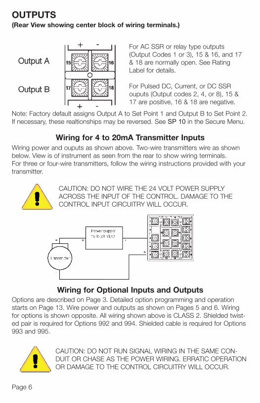
OUTPUTS(Rear View showing center block of wiring terminals.)
Output A
Output B
For AC SSR or relay type outputs(Output Codes 1 or 3), 15 & 16, and 17& 18 are normally open. See RatingLabel for details.
For Pulsed DC, Current, or DC SSRouputs (Output codes 2, 4, or 8), 15 &17 are positive, 16 & 18 are negative.
Note: Factory default assigns Output A to Set Point 1 and Output B to Set Point 2.If necessary, these realtionships may be reversed. See SP 10 in the Secure Menu.
Wiring power and ouputs as shown above. Two-wire transmitters wire as shownbelow. View is of instrument as seen from the rear to show wiring terminals.For three or four-wire transmitters, follow the wiring instructions provided with yourtransmitter.
CAUTION: DO NOT WIRE THE 24 VOLT POWER SUPPLYACROSS THE INPUT OF THE CONTROL. DAMAGE TO THECONTROL INPUT CIRCUITRY WILL OCCUR.
Wiring for 4 to 20mA Transmitter Inputs
Options are described on Page 3. Detailed option programming and operationstarts on Page 13. Wire power and outputs as shown on Pages 5 and 6. Wiringfor options is shown opposite. All wiring shown above is CLASS 2. Shielded twist-ed pair is required for Options 992 and 994. Shielded cable is required for Options993 and 995.
Wiring for Optional Inputs and Outputs
CAUTION: DO NOT RUN SIGNAL WIRING IN THE SAME CON-DUIT OR CHASE AS THE POWER WIRING. ERRATIC OPERATIONOR DAMAGE TO THE CONTROL CIRCUITRY WILL OCCUR.
OPV1 PCurrePV2 PVoltag992, 9Comm993, 9Comm
949-1265:Layout 1 1/25/11 10:22 AM Page 6
Page 7
17
&
nt 2.nu.
n
our
gwist-ons
-ON
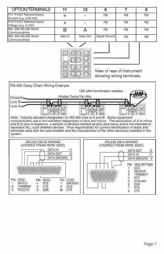
OPTION/TERMINALS 11 12 6 7 8PV1 PV/SV Retransmission, Current (e.g. 4-20 mA)
+ - na na na
PV2 PV/SV Retransmission,Voltage (e.g. 0-10V)
+ - na na na
992, 996 RS-485 SerialCommunications
B A na na na
993, 995 RS-232 SerialCommunications
Data In Data Out Signal Ground na na
949-1265:Layout 1 1/25/11 10:22 AM Page 7
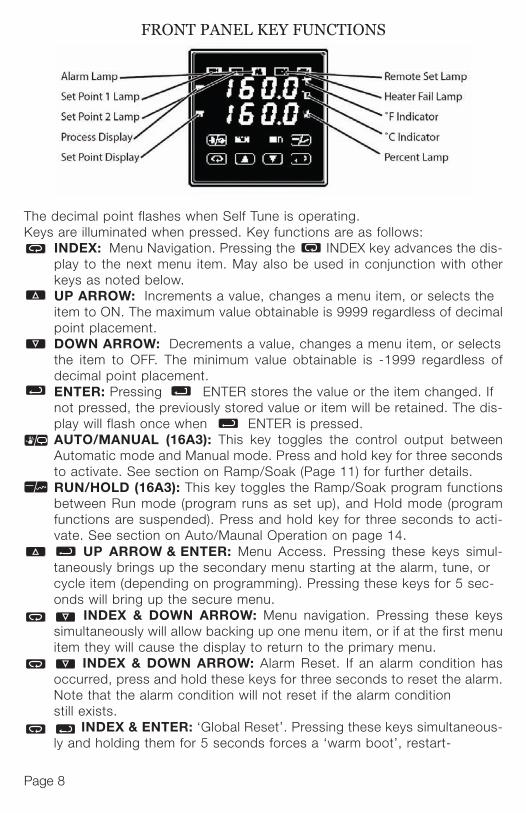
The decimal point flashes when Self Tune is operating.Keys are illuminated when pressed. Key functions are as follows:
INDEX: Menu Navigation. Pressing the INDEX key advances the dis-play to the next menu item. May also be used in conjunction with otherkeys as noted below.UP ARROW: Increments a value, changes a menu item, or selects the item to ON. The maximum value obtainable is 9999 regardless of decimalpoint placement.DOWN ARROW: Decrements a value, changes a menu item, or selects the item to OFF. The minimum value obtainable is -1999 regardless ofdecimal point placement.ENTER: Pressing ENTER stores the value or the item changed. If not pressed, the previously stored value or item will be retained. The dis-play will flash once when ENTER is pressed.AUTO/MANUAL (16A3): This key toggles the control output betweenAutomatic mode and Manual mode. Press and hold key for three secondsto activate. See section on Ramp/Soak (Page 11) for further details.RUN/HOLD (16A3): This key toggles the Ramp/Soak program functionsbetween Run mode (program runs as set up), and Hold mode (programfunctions are suspended). Press and hold key for three seconds to acti-vate. See section on Auto/Maunal Operation on page 14.
Page 8
. UP ARROW & ENTER: Menu Access. Pressing these keys simul-taneously brings up the secondary menu starting at the alarm, tune, or cycle item (depending on programming). Pressing these keys for 5 sec-onds will bring up the secure menu.
. INDEX & DOWN ARROW: Menu navigation. Pressing these keyssimultaneously will allow backing up one menu item, or if at the first menuitem they will cause the display to return to the primary menu.
INDEX & DOWN ARROW: Alarm Reset. If an alarm condition hasoccurred, press and hold these keys for three seconds to reset the alarm.Note that the alarm condition will not reset if the alarm condition still exists.
. INDEX & ENTER: ‘Global Reset’. Pressing these keys simultaneous-ly and holding them for 5 seconds forces a ‘warm boot’, restart-
FRONT PANEL KEY FUNCTIONS ing tery f
A
bCorrkeysrese
Whilsecovaluethe dare d
NOT
DOW
Fourchan
tableitemsecu
ExamUP A1101valueThe thesthis
949-1265:Layout 1 1/25/11 10:22 AM Page 8

dis-ther
he imal
ects s of
. If dis-
weenonds
ionsram
acti-
mul-or ec-
keysmenu
hasarm.
ous-
Page 9
ing the control (similar to turning power off and on). ‘Global Reset’ will allow recov-ery from errors and reset the following menu items:
AL i.H: Alarm inhibit 0PEn 1nP: Input error
bA nP: Input err CHEC CAL: Check calibrationCorrect the problems associated with the above conditions before using the resetkeys. More than one error could present. Caution is advised since several items arereset at one time.
While in the Primary or Secondary Menu, if no key is pressed for a period of 30seconds, the display will return to the HOME position displaying the temperaturevalue. While in the Secure Menu, if no key is pressed for a period of 60 seconds,the display will return to HOME position displaying the temperature value. Outputsare disabled (turned off) when the Secure Menu is active.
NOTE: To move the Primary Menu quickly from any other menu, press the UP ARROW & ENTER keys followed by pressing the INDEX &
DOWN ARROW keys.
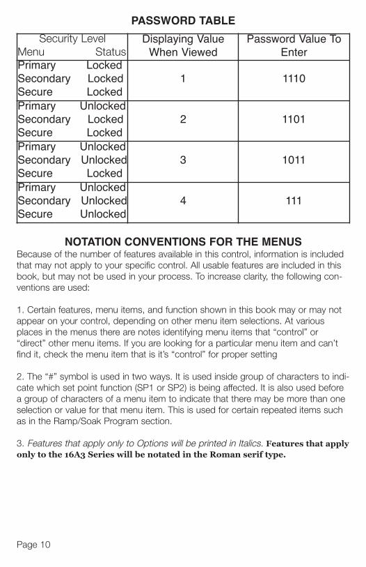
SECURITY LEVEL SELECTIONFour levels of security are provided. The display shows the current security level. Tochange security levels, change the password value using the UP ARROW and
DOWN ARROW keys and press the ENTER key. Refer to the passwordtable for the correct value to enter for the security level desired. The SECr menuitem security level may be viewed or changed at any time regardless of the presentsecurity level.
Example: To set security access level to 2, at the SECr menu item, press the UP ARROW key until the upper display shows the password for level 2 access,1101. Press the ENTER key. The display will blink and return with the levelvalue, 2, in the upper display.The password values shown in the table cannot be altered, so retain a copy ofthese pages for reference. This is the only reference made to password values inthis intruction book.
949-1265:Layout 1 1/25/11 10:22 AM Page 9
The funcperaSet V
ItemRun/Desc
If thedispbut tcentber sbut pthe oOpe
If PrPresProg
If PcpercAutothe othe cperc
Erro
The set pgramany
The
The Rathper m
i
Page 10
NOTATION CONVENTIONS FOR THE MENUSBecause of the number of features available in this control, information is includedthat may not apply to your specific control. All usable features are included in thisbook, but may not be used in your process. To increase clarity, the following con-ventions are used:
1. Certain features, menu items, and function shown in this book may or may notappear on your control, depending on other menu item selections. At variousplaces in the menus there are notes identifying menu items that “control” or“direct” other menu items. If you are looking for a particular menu item and can’tfind it, check the menu item that is it’s “control” for proper setting
2. The “#” symbol is used in two ways. It is used inside group of characters to indi-cate which set point function (SP1 or SP2) is being affected. It is also used beforea group of characters of a menu item to indicate that there may be more than oneselection or value for that menu item. This is used for certain repeated items suchas in the Ramp/Soak Program section.
3. Features that apply only to Options will be printed in Italics. Features that applyonly to the 16A3 Series will be notated in the Roman serif type.
Security LevelMenu Status
Displaying ValueWhen Viewed
Password Value ToEnter
Primary LockedSecondary LockedSecure Locked
1 1110
Primary UnlockedSecondary LockedSecure Locked
2 1101
Primary UnlockedSecondary UnlockedSecure Locked
3 1011
Primary UnlockedSecondary UnlockedSecure Unlocked
4 111
PASSWORD TABLE
949-1265:Layout 1 1/25/11 10:22 AM Page 10
Page 11
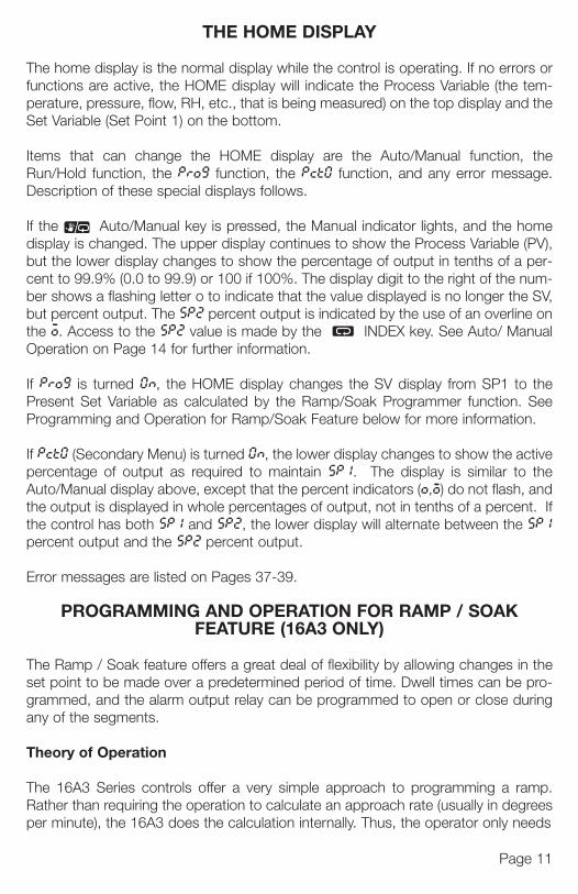
THE HOME DISPLAY
The home display is the normal display while the control is operating. If no errors orfunctions are active, the HOME display will indicate the Process Variable (the tem-perature, pressure, flow, RH, etc., that is being measured) on the top display and theSet Variable (Set Point 1) on the bottom.
Items that can change the HOME display are the Auto/Manual function, theRun/Hold function, the Pro9 function, the Pct0 function, and any error message.Description of these special displays follows.
If the Auto/Manual key is pressed, the Manual indicator lights, and the homedisplay is changed. The upper display continues to show the Process Variable (PV),but the lower display changes to show the percentage of output in tenths of a per-cent to 99.9% (0.0 to 99.9) or 100 if 100%. The display digit to the right of the num-ber shows a flashing letter o to indicate that the value displayed is no longer the SV,but percent output. The SP2 percent output is indicated by the use of an overline onthe o. Access to the SP2 value is made by the INDEX key. See Auto/ ManualOperation on Page 14 for further information.
If Pro9 is turned 0n, the HOME display changes the SV display from SP1 to thePresent Set Variable as calculated by the Ramp/Soak Programmer function. SeeProgramming and Operation for Ramp/Soak Feature below for more information.
If Pct0 (Secondary Menu) is turned 0n, the lower display changes to show the activepercentage of output as required to maintain SP1. The display is similar to theAuto/Manual display above, except that the percent indicators (o,o) do not flash, andthe output is displayed in whole percentages of output, not in tenths of a percent. Ifthe control has both SP1 and SP2, the lower display will alternate between the SP1percent output and the SP2 percent output.
Error messages are listed on Pages 37-39.
PROGRAMMING AND OPERATION FOR RAMP / SOAK FEATURE (16A3 ONLY)
The Ramp / Soak feature offers a great deal of flexibility by allowing changes in theset point to be made over a predetermined period of time. Dwell times can be pro-grammed, and the alarm output relay can be programmed to open or close duringany of the segments.
Theory of Operation
The 16A3 Series controls offer a very simple approach to programming a ramp.Rather than requiring the operation to calculate an approach rate (usually in degreesper minute), the 16A3 does the calculation internally. Thus, the operator only needs
i
i
edhison-
ot
’t
indi-oreonech
pply
To
949-1265:Layout 1 1/25/11 10:22 AM Page 11
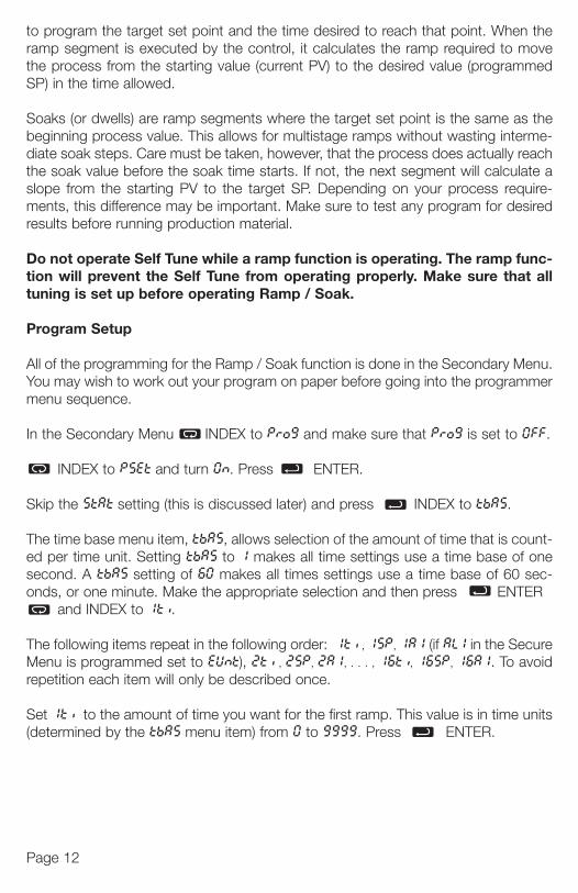
to program the target set point and the time desired to reach that point. When theramp segment is executed by the control, it calculates the ramp required to movethe process from the starting value (current PV) to the desired value (programmedSP) in the time allowed.
Soaks (or dwells) are ramp segments where the target set point is the same as thebeginning process value. This allows for multistage ramps without wasting interme-diate soak steps. Care must be taken, however, that the process does actually reachthe soak value before the soak time starts. If not, the next segment will calculate aslope from the starting PV to the target SP. Depending on your process require-ments, this difference may be important. Make sure to test any program for desiredresults before running production material.
Do not operate Self Tune while a ramp function is operating. The ramp func-tion will prevent the Self Tune from operating properly. Make sure that alltuning is set up before operating Ramp / Soak.
Program Setup
All of the programming for the Ramp / Soak function is done in the Secondary Menu.You may wish to work out your program on paper before going into the programmermenu sequence.
In the Secondary Menu INDEX to Pro9 and make sure that Pro9 is set to 0FF.
INDEX to PSEt and turn 0n. Press ENTER.
Skip the StAt setting (this is discussed later) and press INDEX to tbAS.
The time base menu item, tbAS, allows selection of the amount of time that is count-ed per time unit. Setting tbAS to 1 makes all time settings use a time base of onesecond. A tbAS setting of 60 makes all times settings use a time base of 60 sec-onds, or one minute. Make the appropriate selection and then press ENTER
and INDEX to 1ti.
The following items repeat in the following order: 1ti , 1SP, 1A1 (if AL1 in the SecureMenu is programmed set to EUnt), 2ti , 2SP, 2A1, . . . , 16ti, 16SP, 16A1. To avoidrepetition each item will only be described once.
Set 1ti to the amount of time you want for the first ramp. This value is in time units(determined by the tbAS menu item) from 0 to 9999. Press ENTER.
Set like tempset i
Presthenset Alarm
Com16SP
For uset tpoinyou
The contrepeputs
It is the ped. Rbegiferen
Ram
Whemenor byDOW
The HOLthree
To sagai
Page 12
949-1265:Layout 1 1/25/11 10:22 AM Page 12

n themovemed
s therme-eachate auire-sired
unc-t all
enu.mmer
0FF.
ount-onesec-ER
cureavoid
units
Set 1SP to the target value desired for the first ramp. This value is in actual units justlike SP1. If the control is programmed for temperature, then the SP displays are intemperature. If the control is programmed for some other engineering unit, the SP isset in that unit.
Press INDEX to continue. If Alarm 1 is programmed as an event (AL1 = EUnt),then 1A1 will appear. If you wish the Alarm 1 contact to function for this segment,set 1A1 is set to 0n. If not, set for 0FF. Press ENTER. When 1A1 is set 0n, theAlarm 1 function will be active for entire period set 1t above.
Complete setting the segment times (2ti . . . 16ti ), segment set point (2SP . . .16SP), and event alarms (2A1 . . . 16A1) to 0n or 0FF.
For unneeded or unused segments set the segment times (2ti . . . 16ti ) to 0, andset the segment set point (2SP . . . 16SP) to the same value as the last active setpoint. A segment alarm may be set to indicate “end of run” at the segment numberyou select.
The last menu item for the ramp / soak function is PEnd. PEnd determines what thecontrol does when the program has ended. You may choose to have the programrepeat (LooP), HoLd the last set point (16SP), revert to the local SP1, or turn the out-puts off (0oFF).
It is important to remember that if you want the program to repeat, you must allowthe process to return to the same condition that existed when the program first start-ed. Remember that the ramp function calculates the slope by drawing a line from thebeginning PV to the ramp target set point. If the PV at the end of the program is dif-ferent than the PV at the initial start, the ramp will calculate differently.
Ramp / Soak Operation
When you wish to start the program, enter the Secondary Menu and set the Pro9menu item on 0n. Return to the HOME position by waiting for the display to time outor by pressing the UP ARROW & ENTER keys and then the DOWN ARROW & INDEX keys.
The home display will read as it normally does. The HOLD indicator by the RUN /HOLD key will be lit. To start the program press the RUN / HOLD key forthree seconds. The HOLD indicator will go out, and the program will start.
To suspend the program at any time, press the RUN / HOLD key. Press the keyagain to resume.
Page 13
949-1265:Layout 1 1/25/11 10:22 AM Page 13

Page 14
Pressing the AUTO / MANUAL key will also suspend the program operation.The difference is that AUTO / MANUAL also puts the control into manual mode. SeeAuto / Manual operation on page 14.
The function of the Primary Menu will change depending on the setting of the StAtmenuitem in the Secondary Menu. If StAt is 0FF then the Primary Menu is not changed.
If the StAt menu item is set 0n, then the Primary Menu has three additional informa-tion items added before SP1 appears. The first INDEX item displays the time remain-ing in the current segment in the top display (####), and the message ti , in thelower display. The next INDEX item displays the total time for the active segment inthe upper display (####) and the message ##ti (1ti . . . 16ti ), in the lower dis-play. The third INDEX item displays the segment set value (####) in the top display,and the message ##SP (1SP . . . 16SP) in the lower display. The next INDEX pressresumes the normal Primary Menu.
The trol. troubAL kplay be this us
If yoDOWimpofull cS20H
(Assfor Aand set t
To reMANbumprocPV is
949-1265:Layout 1 1/25/11 10:22 AM Page 14
tion.See
menu
rma-main-n thent indis-
play,ress
Page 15
AUTO / MANUAL OPERATION (16A3 ONLY)
The AUTO / MANUAL function allows you to manually adjust the output of the con-trol. This is normally used during process setup or start up. It can also be used fortroubleshooting. To switch from AUTO to MANUAL press the AUTO / MANU-AL key and hold for three seconds. The MANual indicator will light and the lower dis-play will change from normal to showing the actual output in percent. The value willbe the actual percentage of output that was active when the key was pressed. Thisis usually known as “bumpless transfer”.
If you wish to change the output while in manual, press the UP ARROW or DOWN ARROW keys to change the value, and press ENTER to retain it. It isimportant to remember that the value of the display can be read as 0 to 100% of thefull control output, or 0 to 100% of the range between S10L and S10H or S20L andS20H. If APCt is set for rEAL, a reading of 50% in MANUAL represents 10 mA(Assuming a current output regardless of the S10L and S10H settings.) If APCt is setfor AdJ, then 50% in MANUAL will represent the mid point in output between S10Land S10H. (Assuming a current output, 4 to 20 mA, with S10L set to 20 and S10Hset to 100, 50% will represent 12 mA.)
To return to AUTOmatic control, press the AUTO / MANUAL key again. TheMANual indicator will go out, and the set point will take over. However, if you wantbumpless transfer back to AUTO, slowly change the percentage of output until theprocess variable matches (or at least is close) to the set point. The further away thePV is from the set point, the greater the “bump” or upset there will be in the out put.
949-1265:Layout 1 1/25/11 10:22 AM Page 15

Page 16
Operating of Self Tune Function
Self Tune allows automatic selection of the necessary parameters to achieve bestcontrol operation from your 16A2 & 16A3 Series control. If you are using the con-trol output as a simple on-off function (0ut 1 set for 0n0F), none of the followingwill apply.
Theory of Operation
The Self Tune function calculates the Pb1, rES, and rtE parameters under the PidtunE selection, and the Fbnd and FrtE parameters, as shown in the SecondaryMenu. These values are determined by measuring the response of the process con-nection to the control. While in this mode the control measures the overshoot andundershoot of the process, and the period of the process (the time from peak valueto the next peak value). These measurements are collected over a period that laststhree periods of overshoot and undershoot. The data collected over this time is effectof Fuzzy Logic on the process is still controlled by the Fint (fuzzy intensity) setting.If Fint is 0, the Fbnd and FrtE will be calculated, but will have no effect. The calcu-lations for the PID values are the same as used in the standard Ziegler - Nicholsequations that have been recognized as standard for decades.
The only modification to the application of the Ziegler - Nichols equations is con-trolled by the dFAC menu item. This menu item controls the amount of rate (deriva-tive) that is applied. A dFAC setting of 3 (factory default) or less allows for less damp-ing. A dFAC setting of 4 allows for critical damping as set forth in Ziegler - Nichols. AdFAC setting of 5 or more allows over damping of the process.
Program Setup and Operation
Do not cool the process or add heat while the tuning is occurring. In the secondarymenu set tunE to SELF. Skip LErn and check to make sure that dFAC is set to thedesired value. Back up to LErn and set to YES. The control will begin the Self Tunefunction. While the Self Tune function is active, the right hand decimal point on thelower display will blink. When Self Tune is complete, the blinking will stop.
After Self Tune is complete, the tunE setting automatic switches to Pid. This allowsexamination and/or modification of the values calculated. We recommended that youdo not change the calculated values unless you have a firm understanding of theparameters involved and their function.
Opti
The a remthrou
Wirecontacro
Selemen
NOTEFFEPOWAND
In opputethe SL0rE
auto
If yowishthe Lexpeset bTo c
949-1265:Layout 1 1/25/11 10:22 AM Page 16

Page 17
eston-ng
Pid
darycon-and
valueastsffectting.alcu-chols
con-riva-
amp-ls. A
daryo theTunen the
ows youf the
OPERATION AND PROGRAMMING OF OPTIONS
Option 992, 993, 995, 996 Serial Communication
The serial communications options allow the control to be written to and read froma remote computer or other similar digital device. Communication is allowed eitherthrough a RS-485 (Option 992, 996) port, or a RS-232 (Option 993, 995) port.
Wire the communication lines as shown on Page 7. Wiring for the RS-485 is run fromcontrol to control in a daisy chain fashion with a termination resistor (120 ohms)across the transmit and receive terminals of the last control in the chain.
Select the control address and communication baud rate with the Addr and bAUdmenu items in the Secure Menu.
NOTE: THE BAUD RATE AND ADDRESS MENU ITEM SETTINGS WILL TAKEEFFECT ON THE NEXT POWER UP OF THE CONTROL. BE SURE TO TURN THEPOWER TO THE CONTROL OFF AND ON BEFORE USING THE NEW BAUD RATEAND ADDRESS VALUES.
In operation, you have the option of preventing a write command from the host com-puter. To prevent the host from writing to the control change the L0rE menu item inthe Secondary Menu to L0C. To allow the host to write commands to the control setL0rE to rE. (The host does have the ability to change the L0rE state, but it is notautomatic.)
If your system depends on constant reading or writing to and from the host, you maywish to set the No Activity Timer (nAt) to monitor the addressing of the control. Whenthe L0rE is set to rE and the nAt is set to any value other than Off, the control willexpect to be addressed on a regular basis. If the control is not addressed in the timeset by the value of nAt, then the control will display the error message CHEC L0rE.To clear the message set L0rE to L0C.
949-1265:Layout 1 1/25/11 10:22 AM Page 17

Page 18
Serial Communications Options and Non-volitile Memory
There are many different types of memory used in computer driven devices. Theterms RAM (random access memory) and ROM (read only memory) are a couplewith which you may be familiar.
RAM is used in computers to run programs and hold data for a short period of time.This is the memory that is used primarily in PCs. RAM is very fast and can be readand written to over and over again.
ROM is used in computers to hold the ‘permanent’ programming that allows a PCto start. This memory is ‘burned in’ to the chip itself and can not be changed. UnlikeRAM, however, this memory is permanent. While it can not be changed, it can notlose its programming when power is turned off.
There is a third type of memory that is now currently used to combine the character-istics of both RAM and ROM. This is known as EEPROM (electrically erasable pro-grammable read only memory). While the name may be long and somewhat cryptic,the EEPROM can be erased and re-written many times, and yet hold the pro-grammed data even over long periods of time when the power is off. This is the typeof memory that all Love Controls uses to save the settings your program in your con-trol. The reliability and longevity of the data retention is what allows us to guaranteea 10 year data retention without power.
In normal operation, the control uses RAM, just as any other computerized device.Whenever you make a change to one of the parameters in the control, the set pointfor example, the new value is written into the EEPROM. This way, if power goes offfor whatever reason, when power resumes, the latest settings are preserved. Whenpower is turned on, the data is copied from the EEPROM to the RAM to begin oper-ation.
If EEPROM is such a wonderful thing, you might ask, why bother with RAM? Onereason is that RAM is much faster than EEPROM. Faster speed gives you better per-formance in critical control functions.
Perhaps the most important reason is that EEPROM has a limit to the number oftimes it can be erased and re-written. Current technology now sets that limit at aboutone million erase/write cycles. In a dynamic control situation, it may be necessary toupdate RAM every few milliseconds. EEPROM can not keep up to that pace, and,even if it could, it would be ‘used up’ in a matter of days.
If yomingto us
Addpictutionscycle
Usuaputesitor
All 1only mento Rupda
The
If yorecomari
Mak
If yocont
949-1265:Layout 1 1/25/11 10:22 AM Page 18
Page 19
Theuple
ime.read
a PCnlike
n not
cter-pro-ptic,pro-typecon-ntee
vice.points off
Whenper-
Oneper-
er ofboutry toand,
If you think about how long it would take a million changes to the control program-ming through the front key pad, you will see that it would take a very long time to getto use up the life of the EEPROM.
Adding one of the computer communications options (e.g. 992, 993) changes thepicture. The speed of computer communications is such that hundreds of instruc-tions can be made in less than a minute. In such a situation, the million erase/writecycles could be used up in a couple of months causing the control to fail.
Usually in such a situation, the control is under close observation by the host com-puter. It may not be necessary, then to the data written to the EEPROM, as it is ‘tran-sitory’ in nature (changing set points for a ramp/soak sequence for example).
All 16A Series controls with communications options made before April 2001 areonly able to write to the EEPROM. Controls manufactured after this date have amenu item in the Secure menu (Stor) that allows the serial communications to writeto RAM (Stor = no) with a special write command that allows to EEPROM to beupdated or written directly to EEPROM (protocol command 0442).
The factory default is ‘write to EEPROM’ (Stor = YES).
If your computer system will be making frequent changes to the control we stronglyrecommend that you select the ‘write to RAM’ parameters (Stor = no). If you are pri-marily reading from the control, there is no need to change the setting.
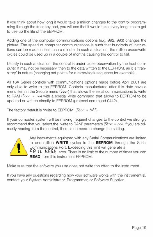
Any instruments equipped with any Serial Communications are limitedto one million WRITE cycles to the EEPROM through the SerialCommunications Port. Exceeding this limit will generate a FA1L tESt error. There is no limit to the number of times you canREAD from this instrument EEPROM.
Make sure that the software you use does not write too often to the instrument.
If you have any questions regarding how your software works with the instrument(s),contact your System Administrator, Programmer, or Software Supplier.
949-1265:Layout 1 1/25/11 10:22 AM Page 19

0utMENU SELECTIONS
PRIMARY MENUPress INDEX to advance to the next menu item. Press UP ARROW or
DOWN ARROW to change the value in the display. Press ENTER toretain the value. If StAt, (Secondary Menu [16A3]), is 0n, the three program statusmenu items shown on Page 14 will precede the folowing.
SP1 Set Point 1 Adjust, Control Point 1.
SP2 Set Point 2 Adjust (if equipped), Control Point 2.
SECONDARY MENUHold UP ARROW & ENTER. Press INDEX to advance to the nextmenu item. Press UP ARROW or DOWN ARROW to change the valuein the display. Press ENTER to retain the value.
A1Lo Alarm 1 Low: The Low Alarm point is usually set below the Set Point. May not appear depending on AL1 setting in Secure Menu.
A1Hi Alarm 1 High: The High Alarm Point is usually set above the Set Point. May not appear depending on AL1 setting in Secure Menu.
Page 20
949-1265:Layout 1 1/25/11 10:23 AM Page 20
0ut1 Output selection: Select 0n0F, #tP, #PuL, or ProP.
0n0F A setting of 0n0F allows the control to operate in simple on/off mode. This setting forces the control to turn off at set point, and on at the set point plus the differential (SP1d). When selected, the 0ut1 0n0Fmenu items is followed by #### SP 0d, and the tunE, Pb, rES, 510L and 510H selections in the Secure menu are suppressed.
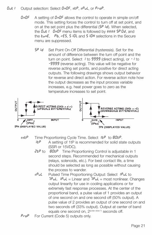
SP1d Set Point On-Off Differential (hysteresis). Set for the amount of difference between the turn off point and the turn on point. Select 1 to 9999 (direct acting), or -1 to -9999 (reverse acting). This value will be negative for reverse acting set points, and positive for direct acting outputs. The following drawings shows output behavior for reverse and direct action. For reverse action note how the output decreases as the input process variable increases, e.g. heat power goes to zero as the temperature increases to set point.
##tP Time Proportioning Cycle Time. Select 1tP to 80tP.1tP A setting of 1tP is recommended for solid state outputs
(SSR or 15VDC).2tP to 80tP Time Proportioning Control is adjustable in 1
second steps. Recommended for mechanical outputs (relays, solenoids, etc.). For best contact life, a time should be selected as long as possible without causing the process to wander.
#PuL Pulsed Time Proportioning Output: Select 1PuL to7PuL. 1PuL = Linear and 7PuL = most nonlinear. Changesoutput linearity for use in cooling applications or for extremely fast response processes. At the center of the proportional band, a pulse value of 1 provides an output of one second on and one second off (50% output). A pulse value of 2 provides an output of one second on andtwo seconds off (33% output). Output at center of band equals one second on, 2(pulse value-1) seconds off.
ProP For Current (Code 5) outputs only.
W or R toatus
nextvalue
May
May
Page 21
949-1265:Layout 1 1/25/11 10:23 AM Page 21
The following menu items apply only if your control is equipped with a sec-ond set point (last digit of model number is not zero). If your control doesnot have a second set point, jump to the tunE menu on the next page.
0ut2 Output selection: Select OnOF, #tP, #PuL, or ProP.0n0F A setting of 0n0F allows the control to operate in simple on/off
mode. This setting forces the control to turn off at set point, and on at the set point plus the differential (SP2d). When selected, the 0ut2/0n0F menu item is followed by #### SP2d, and the Pb2 selection in the Secondary menu and the S20L and S20Hselections in the Secure menu are suppressed.SP2d Set Point On-Off Differential (hysteresis). Select 1 to
9999 (direct acting), or -1 to -9999 (reverse acting). See SP1d on the previous page.
##tP Time Proportioning Cycle Time. Select 1tP to 80tP. 1tP A setting of 1tP is recommended for solid state outputs
(SSR or 15VDC).2tP to 80tP Time Proportioning Control is adjustable in 1
second steps. Recommended for mechanical outputs (relays, solenoids, etc.). For best contact, life, a time should be selected as long as possible without causing the process to wander.
#PuL Pulsed Time Porpotioning Output: Select 1PuL to 7PuL. 1PuL = Linear and 7PuL = most nonlinear. Changes
output linearity for use in cooling applications or for extremely fast response processes. At the center of the proportional band, a pulse value of 1 provides an output of one second on and one second off (50% output). A pulse value of 2 provides an output of one second on andtwo seconds off (33% output). Output at center of band equals one second on, 2(pulse value -1) seconds off.
ProP For Current (Code 5) outputs only.
SP
#SP
NoteThennumindic
#tuntunE
Page 22
949-1265:Layout 1 1/25/11 10:23 AM Page 22
sec-es
f nd
ts
g
L.
e put A
andnd
SP (Option 948, 4-Stage Set Point) Active Set Point Stage. Select 1SP1, 25P1,35P1, 45P1. (See Page 17 for more detail.)1SP1 Set Menu Items to display Stage 1 for view and change access. If
SPSA is set for 1nt, 1SP1 is made active.25P1 Set Menu Items to display Stage 2 for view and change access. If
SPSA is set for Int, 25P1 is made active.35P1 Set Menu Items to display Stage 3 for view and change access. If
SPSA is set for Int, 35P1 is made active.45P1 Set Menu Items to display Stage 4 for view and change access. If
SPSA is set for 1nt, 45P1 is made active.
#SP1 (Option 948, 4-Stage Set Point) Adjust Control Point 1 for Stage selected above.
Note: The menu items for tunE (below) are modified when Option 948 is active.Then, the menu items are shortened or shifted right, and preceded with the stagenumber selected in SP above. Each stage has its own set of tunE parameters asindicated by #tun.
#tun (Option 948, 4-Stage Set Point) ortunE Tuning Choice: Select SELF, Pid, SL0, nor, or FASt.
SELF The Controller will evaluate the Process and select the PID valuesto maintain good control. Active for SP1 only.LErn Select YES or no
YES Start Learning the Process. After the process hasbeen learned the menu item will revert to no.
no Learning will stay in present mode.dFAC Damping factor, select 0FF, 1 to 7. Sets the ratio of Rate
to Rate for the SEL tunE mode. 7 = most Rate. Factory setto 3. For a fast response process the value should be low-ered (less Rate). For a slower process the value should beincreased (more Rate).
Pid Manually adjust the PID values. PID control consists of three basicparameters, Proportional Band (Gain), Reset Time (Integral), and Rate Time (Derivative).Pb1 Proportional Band (Bandwidth). Select 1 to 9999°F, °C,
or counts.Pb2 Proportional Band (Bandwidth). Select 1 to 9999°F, °C,
or counts. Appears only if control is equipped with secondset point and 0ut2 is NOT selected as 0n0F.
Page 23
949-1265:Layout 1 1/25/11 10:23 AM Page 23

FrtE
PEA
UAL
Pct0
Pro9
PSEt
StAt
Page 24
rES Automatic Reset Time. Select 0FF, 0.1 to 99.9 minutes. Select 0FF to switch to 0FS.
0FS Manual Offset correction Select. Select 0FF, 0.1 to 99.9percent. Select 0FF to switch to rES.
rtE Rate Time. Select 0FF, 0.1 to 99.9 minutes. Derivative.SL0 PID values are preset for a slow response process.nor PID values are preset for a normal response process.FASt PID values are preset for a fast response process.
Pid2 Linkage of PID parameters between SP1 and SP2: Select 0n or 0FF.0n Applies SP1 rES, rtE, Fbnd, and FrtE terms to SP2 for heat/cool
applications0FF SP2 functions without rES, rtE, Fbnd, and FrtE .
ArUP Anti- Reset Windup Feature: Select 0n or 0FF.0n When ArUP is 0n the accumulated Reset Offset value will be
cleared to 0% when the process input is not within the Proportional Band.
0FF When ArUP is 0FF, the accumulated Reset Offset value is retained in memory when the process input is not within the Proportional Band.
ArtE Approach Rate Time: Select 0FF, 0.01 to 99.99 minutes. The function defines the amount of Rate applied when the input is outside of the Proportional Band. The ArtE time and the rtE time are independent and have no effect on each other. To increase damping effect and reduce over-shoot set the approach rate time for a value greater than the natural rise time of the process (natural rise time = process value time to set point).
Fint Fuzzy Logic Intensity: Select 0 to 100%. 0% is OFF (disables Fuzzy Logic). The function defines the amount of impact Fuzzy Logic will have on the output.
Fbnd Fuzzy Logic Error Band: Select 0 to 4000 °F, °C, or counts. Sets the bandwidth of the Fuzzy Logic. Set Fbnd equal to PID proportional band (Pb1) for best results.
949-1265:Layout 1 1/25/11 10:23 AM Page 24
FrtE Fuzzy Logic Rate of Change: Select 0.00 to 99.99 counts/second. For best initial setting, find the counts/second change of process value near Set Point 1 with output ON 100%. Multiply this value by 3. Set FrtE to this calculated value.
PEA The Peak feature stores the highest input the control has measured since the last reset or Power On. At Power On PEA is reset to the present input. To manually reset the value PEA must be in the lower display. Press the ENTER key to reset. PEA will be reset and display the present input value.
UAL The Valley feature stores the lowest input the Instrument has measured since the last reset or Power On. At Power On UAL is reset to the present input. To manually reset the value UAL must be in the lower display. Press the ENTER key. UAL will be reset and display the present input value.
Pct0 Percent Output Feature: Select 0n or 0FF. 0n When selected 0n, the HOME lower display will indicate the output
of the controller in percent. An “o” will appear in the right hand side of the lower display to indicate percent output for SP1. An “ ” will appear on the right hand corner of the lower display to represent percent output for SP2, if the control is so equipped. The display will alternate between these values.
0FF Percent Output display is disabled.
Pro9 Ramp/Soak Feature (16A3): Select 0n or 0FF. 0n Allows Programmed Ramp/Soak function to be started by the
Run/Hold key on the control front panel. 0FF Turns Ramp/Soak function 0FF and resets program to
beginning.
PSEt Programmer function set (16A3): Select 0n or 0FF. 0FF Skip Ramp/Soak Programming. Go to next Secondary Menu
Item, 1nPC on the next page.0n Enable Ramp/Soak Programming.
StAt Programmer Status Display in the Primary Menu when Prog (above) isOn (16A3): Select 0n or 0FF. 0FF The Primary Menu operates as normal.0n The Primary Menu is altered to have the following items
inserted before the SP1 menu item:#### ti time remaining in active segment#### ##ti total time in active segment#### ##SP segment target set point
es.
.9
e.
cool
onal
ned al
nd over-time
gic). e
band1) for
o~
Page 25
949-1265:Layout 1 1/25/11 10:23 AM Page 25
LPbr
L0rE
P0L
P0H
P0Sr
tbAS Ramp/Soak Time Base (16A3): Select 1_S or 60_S. 1_S Ramp/Soak time base is in 1 second increments. Program time
1ti ...16ti is measured in seconds.60_S Ramp/Soak time base is in 60 second increments (minutes).
Program time 1ti ...16ti is measured in minutes.
The following items repeat in the following order: 1ti ,1SP,1A1 (if AL1 is pro-grammed as EUnt), 2ti , 2SP, 2A1, . . . , 16ti, 16SP, 16A1. To avoid repetitioneach item will only be described once.
1ti Segment Time (16A3): Select 0 to 9999 units (minutes if tbAS is set to60_S, seconds if tbAS is set to 1_S).
1SP Segment Set Point (16A3): Set to target value desired.
1A1 Segment Alarm 1 Event (16A3): Select 0n or 0FF. 0n Alarm 1 is active during segment 1 time (1ti).0FF Alarm 1 is inactive during segment 1 time (1ti).
PEnd Program End Action (16A3): Select HoLd or 0oFF. HoLd Stay at the Present Set Point (16SP).0oFF Turn Off SP1 and SP2 Outputs at the end of the program.LooP Repeat program starting at1t.SP1 Revert to SP1 value.
1nPC Input Correction: Select -500 to 0 to 500 °F, °C, or counts. This feature allows the input value to be changed to agree with an external reference orto compensate for sensor error. Note: 1nPC is reset to zero when the inputtype is changed, or when decimal position is changed. Factory default is 0.
FiLt Digital Filter: Select 0FF, 1 to 99. In some cases the time constant of the sensor, or noise, could cause the display to jump enough to be unreadable.A setting of 2 is usually sufficient filtering (2 represents approximately a 1 second time constant). When the 0.1 degree resolution is selected this should be increased to 4. If this value is set too high, controllability will suffer.
Page 26
949-1265:Layout 1 1/25/11 10:23 AM Page 26
LPbr Loop Break Protection: Select 0FF, 1 to 9999 seconds. If, during operation,the output is minimum (0%) or maximum (100%), and the input moves lessthan 5°F (3°C) or 5 counts over the time set for LPbr, the L00P bAd mes-sage will appear. This condition can also be routed to an Alarm Condition ifalarms are present and turned On (see ALbr in the Secure Menu). The loopbreak error can be reset by pressing the ENTER key when at the LPbrmenu item. The INDEX & ENTER keys may also be used.
L0rE (Option 992, 993, 995, 996, Serial Communications) Local / Remote Status:Select L0C or rE. Does not affect other instruments on daisy chain.L0C The host computer is advised that remote write commands will be
rejected. Any write commands sent to this control will be rejected.All read commands are accepted.
rE The host computer is allowed to send write commands. If the control is not addressed within the time set in nAt (No Activity Timer in the Secure Menu) the CHEC LorE error message will be displayed.
P0L (Option 934, 936, Analog Retransmission Output) Process OutputLow: Select -450°F, -260°C, or -1999 counts to any value less than P0H.
P0H (Option 934, 936, Analog Retransmission Output) Process OutputHigh: Select from any value greater than P0L to + 9999°F, +5530°C, or 9999 counts.
P0Sr (Option 934, 936, Analog Retransmission Output) Process OutputSource: Select 1nP or SPt.1nP Process output follows the Process Variable (input).SPt Process output follows the Set Variable (SP1).
time
pro-tion
t to
e ce ornputis 0.
he dable.1
Page 27
949-1265:Layout 1 1/25/11 10:23 AM Page 27

Page 29
ch enu.
ncenge
Unit F, C or nonE.F °F descriptor is On and temperature inputs will be displayed in
actual degrees Fahrenheit.C °C descriptor is On and temperature inputs will be displayed in
actual degrees Celsius.nonE °F and °C descriptors will be Off. This is only available with Current
and Voltage Inputs.
dPt Decimal Point Positioning: Select 0, 0.0, 0.00, 0.000, or .0000. On temperature type inputs a change here will alter the Process Value, SP1, SP2, ALLo, ALHi, and InPC. For current and voltage Inputs all Menu Items related to the Input will be affected.0 No decimal Point is selected. This is available for all Input Types.0.0 One decimal place is available for Type J, K, E, T, L, RTD’s, Current
and Voltage Inputs.0.00 Two decimal places is only available for Current and Voltage Inputs.0.000 Three decimal places is only available for Current and Voltage
inputs..0000 Four decimal places is only available for Current and Voltage inputs.
1nPt Input Fault Timer: Select 0FF, 0.1 to 540.0 minutes. Whenever an Input isout of range (UFL or 0FL displayed), shorted, or open, the timer will start. When the time has elapsed, the controller will revert to the output conditionselected by 1nPb below. If 0FF is selected, the Input Fault Timer will not berecognized (time = infinite).
1nPb Input Fail Action (16A3): Select FA1L, AUE, or PrE. When the Input is out of range (UFL or 0FL displayed) and the Input timer (1nPt) time haselapsed, the controller will revert to the selected condition.
FA1L Outputs are disabled (go to 0% output).AUE The outputs will hold at the last known average percentage of
output.PrE The outputs will maintain preprogrammed percentages of
output as specified in PrE1 and PrE2.PrE1 Preset output for Set Point 1. Select 0 to 100%.PrE2 Preset output for Set Point 2. Select 0 to 100%.
949-1265:Layout 1 1/25/11 10:23 AM Page 29
Page 30
APCt Manual and PctO display adjustment (16A3). Select rEAL or AdJ.rEAL Manual display will display output 0 to 100% relative to actual
range of the output.AdJ Manual display will display output 0 to 100% relative to the
S#0L and S#0H settings.
SEnC Sensor Rate of Change: Select 0FF, 1 to 4000 °F, °C, or counts per 1 second period. This value is usually set to be slightly greater than the fastest process response expected during a 1 second period, but measured for at least 2 seconds. If the process is faster than this setting, the SEnC bAderror message will appear. The outputs will then be turned off. This function can be used to detect a runaway condition, or speed up detection of an open thermocouple. Use the INDEX & ENTER keys to reset.
SCAL Scale Low: Select 100 to 11998 counts below SCAH. The total span between SCAL and SCAH must be within 11998 counts. Maximum setting range is -1999 to +9999 counts. For Current and Voltage inputs, this will set the low range end. Value not adjustable for Thermocouple and RTD ranges.
SCAH Scale High: Select 100 to 11998 counts above SCAL. The total span between SCAL and SCAH must be within 11998 counts. Maximum setting range is -1999 to +9999 counts. For Current and Voltage inputs, this will set the high range end. Value not adjustable for Thermocouple and RTD ranges.
SPL Set Point Low: Select from the lowest input range value to SPH value. This will set the minimum SP1 or SP2 value that can be entered. The values for SP1 or SP2 will stop moving when this value is reached.
SPH Set Point High: Select from the highest input range value to SPL value. This will set the maximum SP1 or SP2 value that can be entered. The values forSP1 or SP2 will stop moving when this value is reached.
SP10 Set Point 1 Output Select: Select 0utA or 0utb.0utA Set Point 1 is routed through Output A, Set Point 2 (if equipped) is
routed through Output B.0utb Set Point 1 is routed through Output B, Set Point 2 (if equipped) is
routed through Output A.
S1S
If 0uappe
S10
S10
If 0u
If 0umakinforPage
NoteS1r
pow
S1r
949-1265:Layout 1 1/25/11 10:23 AM Page 30

Page 31
ctual
e
stest or at d
ction an et.
ng l set ges.
ng l set ges.
This s for
This s for
d) is
d) is
S1St Set Point 1 state : Select dir or rE.dir Direct Action. As the input increases the output will increase. Most
commonly used in cooling processes.
rE Reverse Action. As the input increases the output will decrease. Most commonly used in heating processes.
If 0ut1 (Page 21) is set for ##tP, #PUL, or ProP, then S10L and S10Lappear. If 0ut1 is set for 0n0F, then skip S1rE.
S10L Set Point Output Low Limit. Select 0 to 100% but not greater than S10H.This item limits the lowest output value. This is useful for adding a bias to the process when needed. Factory set to 0 for outputs codes 1, 2, 3, 4, and 8. Factory set to 20 for output code 5 (20% out put equals 4 mA output).
S10H Set Point 1 Output High Limit. Select 0 to 100% but not less than S10Lfor output codes 1, 2, 3, 4, or 8. Select 0 to 102% but not less than
S10L for output code 5. This item allows setting the maximum output limit. This is useful with processes that are over powered. Adjustment to 102% allows seeting current output to force a full on condition for output devices which do not have bias adjustments. Factory set to 100 for all output codes.
If 0ut1 is set for ##tP, #PUL, or ProP, then skip to S1LP below.
If 0ut1 is set to 0n0F (in Secondary Menu), then the next three menu items canmake the SP1 and SP1d settings act like a high or low alarm set point. See theinformation on alarm settings and the cautions and warnings that apply to them onPages 30-31.
Note that when Set Point 1 Power Interrupt, S1P, is 0n, and Set Point 1 Reset,S1rE, is programmed to HoLd, the SP1 output will automatically reset upon apower failure and subsequent restoration, if the process is below SP1.
S1rE Set Point 1 Reset. Select 0n0F or HoLd.0n0F Output will automatically reset when process passes back
through SP1d.HoLd Manual Reset. Reset by simultaneously pressing the
INDEX & DOWN ARROW keys for 3 seconds.
949-1265:Layout 1 1/25/11 10:23 AM Page 31
Page 32
S1Pi Set Point 1 Power Interrupt. Select 0n or 0FF.0n Alarm Power Interrupt is 0n. Output will automatically
reset on power-up if no alarm condition exists.
0FF Alarm Power Interrupt is 0FF. Output will be in thealarm condition on power-up regardless of condition ofprocess.
S1iH Set Point 1 Inhibit: Select 0n or 0FF.0n Alarm Inhibit is On. Alarm action is suspended until the
process value first enters a non-alarm condition.
0FF Alarm Inhibit is OFF.S1LP Set Point Lamp: Select 0 on or 0oFF.
0 on Lamp ON when Output is ON.0oFF Lamp OFF when Output is ON.
If your control is not equipped with Set Point 2, then proceed to thealarm section (next page).
S2t Set Point 2 type: Select Ab or dE.AbS Absolute SP2. SP2 is independent of SP1, and may be
set anywhere between the limits of SPL and SPH.dE Deviation SP2. SP2 is set as a deviation from SP1, and
allows SP2 to retain its relationship with SP1 when SP1is changed (SP2 tracks SP1).
S2St Set Point 2 State: Select dir or rE.dir Direct Action. As the input increases the output will
increase. Most commonly used in cooling processes.
rE Reverse Action. As the input increases the output willdecrease. Most commonly used in heating processes.
If 0ut2 is set for ##tP, #PUL, or ProP, then S20L and S20H appear. If 0ut2is set for 0n 00F, then skip S20L and S20H.
S20L Set Point Output Low Limit: Select 0 to 100% but not greater thanS20H. This item limits the lowest output value. This is useful foradding a bias to the process when needed. Factory set to 0 foroutput codes 1,2, 3, 4, and 8. Factory set to 20 for output code 5(20% output equals 4 mA output).
S20H Set Point 2 Output High Limit: Select 0 to 100% but not less thanS20L for output codes 1, 2, 3, 4, or 8. Select 0 to 102% but notless than S20L for output code 5. This item allows setting themaximum output limit. This is useful with processes that are overpowered. Adjustment to 102% allows setting current output to
If 0uitempointhat
Note2 Rerese
belo
S2r
S2P
S2
S2L
ALA
Whethe vtion
949-1265:Layout 1 1/25/11 10:23 AM Page 32
Page 33
ut2
force a full on condition for output devices which do not have bias
adjustments. Factory set to 100 for all output codes.
If 0ut2 is set to 0n0F (in the Secondary Menu), then the next three menuitems can make the SP2 and SP2d settings act like a high or low alarm setpoint. See the information on alarm settings and the cautions and warningsthat apply to them on the next pages.
Note that when Set Point 2 Power Interrupt , S2Pi is On, and Set Point2 Reset, S2rE, is programmed to Hold, the SP2 output will automaticallyreset upon a power failure and subsequent restoration, if the process is
below SP2.
S2rE Set Point 2 Reset. Select 0n0F or Hold.0n0F Output will automatically reset when process passes
back through SP2d.HoLd Manual Reset. Reset (acknowledge) by simultaneously
pressing the INDEX & DOWN ARROW keysfor 3 seconds.
S2Pi Set Point 2 Power Interrupt. Select On or OFF.0n Alarm Power Interrupt is On. Output will automatically
reset on power-up if no alarm condition exists.
0FF Alarm Power Interrupt is OFF. Output will be in the alarm conditionon power-up regardless of condition of process.
S2iH Set Point 2 Inhibit: Select On or OFF.0n Alarm Inhibit is On. Alarm action is suspended until the
process value fi rst enters a non-alarm condition.0FF Alarm Inhibit is OFF.
S2LP Set Point 2 Lamp: Select O on or OoFF.0on Lamp ON when Output is ON.0oFF Lamp OFF when Output is ON.
ALARM TYPE AND ACTION (if alarm function is present)
Caution: In any critical application where failure couldcause expensive product loss or endanger personal safety,a redundant limit controller is required.
When setting an alarm value for an absolute alarm (A1t = AbS), simply setthe value at which the alarm is to occur. When setting the alarm value for a devia-tion alarm (A1t = dE), set the difference in value from the Set Point desired. For
949-1265:Layout 1 1/25/11 10:23 AM Page 33
Page 34
The
AL1
If ALendsSPSA
If AL
A1t
A1rE
A1P
A1iH
A1St
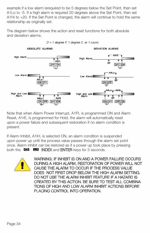
example if a low alarm isrequired to be 5 degrees below the Set Point, then setA1Lo to -5. If a high alarm is required 20 degrees above the Set Point, then setA1Hi to +20. If the Set Point is changed, the alarm will continue to hold the samerelationship as originally set.
The diagram below shows the action and reset functions for both absoluteand deviation alarms.
Note that when Alarm Power Interrupt, A1Pi, is programmed ON and AlarmReset, A1rE, is programmed for Hold, the alarm will automatically resetupon a power failure and subsequent restoration if no alarm condition ispresent.
If Alarm Inhibit, A1iH, is selected ON, an alarm condition is suspendedupon power up until the process value passes through the alarm set pointonce. Alarm inhibit can be restored as if a power up took place by pressingboth the INDEX and ENTER keys for 3 seconds.
WARNING: IF INHIBIT IS ON AND A POWER FAILURE OCCURS DURING A HIGH ALARM, RESTORATION OF POWER WILL NOT CAUSE THE ALARM TO OCCUR IF THE PROCESS VALUE DOES NOT FIRST DROP BELOW THE HIGH ALARM SETTING. DO NOT USE THE ALARM INHIBIT FEATURE IF A HAZARD IS CREATED BY THIS ACTION. BE SURE TO TEST ALL COMBINATIONS OF HIGH AND LOW ALARM INHIBIT ACTIONS BEFORE PLACING CONTROL INTO OPERATION.
949-1265:Layout 1 1/25/11 10:23 AM Page 34
Page 35
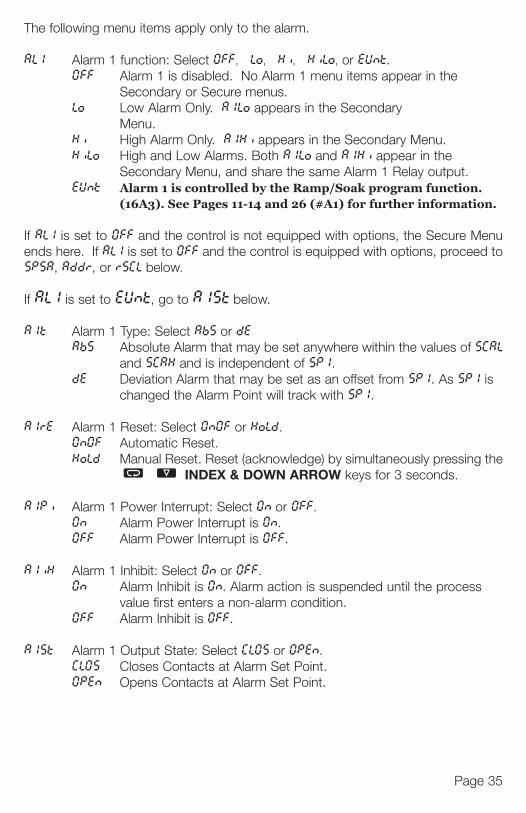
The following menu items apply only to the alarm.
AL1 Alarm 1 function: Select 0FF, Lo, Hi, HiLo, or EUnt.0FF Alarm 1 is disabled. No Alarm 1 menu items appear in the
Secondary or Secure menus.Lo Low Alarm Only. A1Lo appears in the Secondary
Menu.Hi High Alarm Only. A1Hi appears in the Secondary Menu.HiLo High and Low Alarms. Both A1Lo and A1Hi appear in the
Secondary Menu, and share the same Alarm 1 Relay output.EUnt Alarm 1 is controlled by the Ramp/Soak program function.
(16A3). See Pages 11-14 and 26 (#A1) for further information.
If AL1 is set to 0FF and the control is not equipped with options, the Secure Menuends here. If AL1 is set to 0FF and the control is equipped with options, proceed toSPSA, Addr, or rSCL below.
If AL1 is set to EUnt, go to A1St below.
A1t Alarm 1 Type: Select AbS or dEAbS Absolute Alarm that may be set anywhere within the values of SCAL
and SCAH and is independent of SP1.dE Deviation Alarm that may be set as an offset from SP1. As SP1 is
changed the Alarm Point will track with SP1.
A1rE Alarm 1 Reset: Select 0n0F or HoLd.0n0F Automatic Reset.HoLd Manual Reset. Reset (acknowledge) by simultaneously pressing the
INDEX & DOWN ARROW keys for 3 seconds.
A1Pi Alarm 1 Power Interrupt: Select 0n or 0FF.0n Alarm Power Interrupt is 0n.0FF Alarm Power Interrupt is 0FF.
A1iH Alarm 1 Inhibit: Select 0n or 0FF.0n Alarm Inhibit is 0n. Alarm action is suspended until the process
value first enters a non-alarm condition.0FF Alarm Inhibit is 0FF.
A1St Alarm 1 Output State: Select CL0S or 0PEn.CL0S Closes Contacts at Alarm Set Point.0PEn Opens Contacts at Alarm Set Point.
tme
RS NOT
G. S NARE
949-1265:Layout 1 1/25/11 10:23 AM Page 35
Page 36Page 36
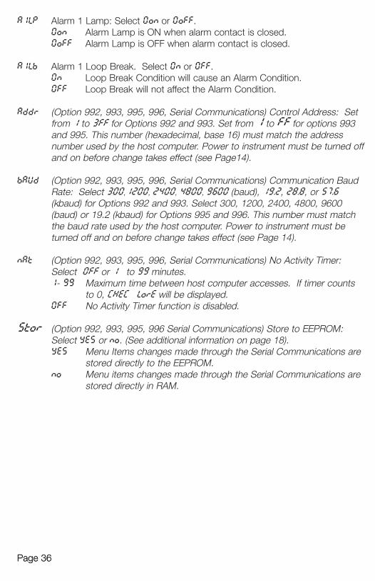
A1LP Alarm 1 Lamp: Select 0on or 0oFF.0on Alarm Lamp is ON when alarm contact is closed.0oFF Alarm Lamp is OFF when alarm contact is closed.
A1Lb Alarm 1 Loop Break. Select 0n or 0FF.0n Loop Break Condition will cause an Alarm Condition.0FF Loop Break will not affect the Alarm Condition.
Addr (Option 992, 993, 995, 996, Serial Communications) Control Address: Setfrom 1 to 3FF for Options 992 and 993. Set from 1 to FF for options 993 and 995. This number (hexadecimal, base 16) must match the address number used by the host computer. Power to instrument must be turned offand on before change takes effect (see Page14).
bAUd (Option 992, 993, 995, 996, Serial Communications) Communication BaudRate: Select 300,1200, 2400, 4800, 9600 (baud), 19.2, 28.8, or 57.6(kbaud) for Options 992 and 993. Select 300, 1200, 2400, 4800, 9600 (baud) or 19.2 (kbaud) for Options 995 and 996. This number must match the baud rate used by the host computer. Power to instrument must be turned off and on before change takes effect (see Page 14).
nAt (Option 992, 993, 995, 996, Serial Communications) No Activity Timer: Select 0FF or 1 to 99 minutes.1- 99 Maximum time between host computer accesses. If timer counts
to 0, CHEC LorE will be displayed.0FF No Activity Timer function is disabled.
Stor (Option 992, 993, 995, 996 Serial Communications) Store to EEPROM: Select YES or no. (See additional information on page 18).YES Menu Items changes made through the Serial Communications are
stored directly to the EEPROM.no Menu items changes made through the Serial Communications are
stored directly in RAM.
DI
A(Altw
A
A
949-1265:Layout 1 1/25/11 10:23 AM Page 36
Page 37
Set993 s ed off
Baud
0 atch e
unts
:
s are
s are
DISPLAY MEANINGSP
OUTPUTSACTION
REQUIRED
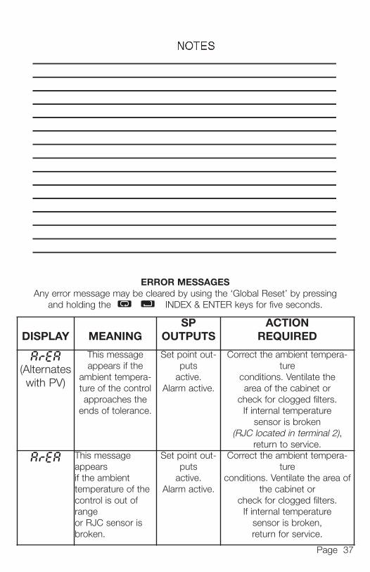
ArEA(Alternateswith PV)
This messageappears if the
ambient tempera-ture of the controlapproaches the
ends of tolerance.
Set point out-puts
active.Alarm active.
Correct the ambient tempera-ture
conditions. Ventilate thearea of the cabinet or
check for clogged filters.If internal temperature
sensor is broken (RJC located in terminal 2),
return to service.
ArEA This messageappearsif the ambienttemperature of thecontrol is out ofrangeor RJC sensor isbroken.
Set point out-puts
active.Alarm active.
Correct the ambient tempera-ture
conditions. Ventilate the area ofthe cabinet or
check for clogged filters.If internal temperature
sensor is broken,return for service.
ERROR MESSAGESAny error message may be cleared by using the ‘Global Reset’ by pressing
and holding the INDEX & ENTER keys for five seconds.
949-1265:Layout 1 1/25/11 10:23 AM Page 37
Page 38
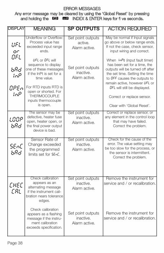
ERROR MESSAGESAny error message may be cleared by using the ‘Global Reset’ by pressing
and holding the INDEX & ENTER keys for fi ve seconds.A
DISPLAY MEANING SP OUTPUTS ACTION REQUIRED
UFL
or
0FL
bAd
1nP
0PEn
1nP
Underflow or Overflow:Process value has
exceeded input rangeends.
UFL or 0FL willsequence to display
one of these messagesif the InPt is set for a
time value.
For RTD inputs RTD isopen or shorted. ForTHERMOCOUPLE
inputs thermocoupleis open.
Set point outputsactive.
Alarm active.
Set point outputsinactive.
Alarm active.
May be normal if Input signalsgo above or below range ends.If not the case, check sensor,
input wiring and correct.
When 1nPt (input fault timer)has been set for a time, the
outputs will be turned off afterthe set time. Setting the timeto 0FF causes the outputs toremain active, however UFL or0FL will still be displayed.
Correct or replace sensor.
Clear with ‘Global Reset’.
L00P
bAd
The sensor may bedefective, heater fuseopen, heater open, orthe final power output
device is bad.
Set point outputsinactive.
Alarm active.
Correct or replace sensor, orany element in the control loop
that may have failed.Correct the problem.
SEnC
bAd
Sensor Rate ofChange exceededthe programmedlimits set for SEnC.
Set point outputsinactive.
Alarm active.
Check for the cause of theerror. The value setting may
be too slow for the process, orthe sensor is intermittent.
Correct the problem.
CHEC
CAL
Check calibrationappears as an
alternating messageif the instrument cali-
bration nears toleranceedges.
Check calibrationappears as a flashingmessage if the instru-
ment calibrationexceeds specification.
Set point outputsinactive.
Alarm active.
Set point outputsinactive.
Alarm active.
Remove the instrument forservice and / or recalibration.
Remove the instrument forservice and / or recalibration.
DIS
Noli
F
t
1
C
C
C
r
C
L
949-1265:Layout 1 1/25/11 10:23 AM Page 38

Page 39
ERROR MESSAGESAny error message may be cleared by using the ‘Global Reset’ by pressing
and holding the INDEX & ENTER keys for fi ve seconds.
D
nalsnds.sor,
er)heftermetoL or.
r.
.
oroop
eay, or.
forion.
forion.
DISPLAY MEANING SP OUTPUTS ACTION REQUIRED
No displaylighted
Display is blank.Instrument is not gettingpower, or the supply volt-
age is too low.
Set point outputsinactive.
Alarm inactive
Check that the powersupply is on, measuresupply voltage, checkthat the external fuses
are good.
FA1L
tESt
Fail test appears uponpower up if the internal
diagnostics detect a fail-ure. This message mayoccur during operation if
a failure is detected.Displays flash.
Fail test may also occurdue to an EEPROM error.
Set point outputsinactive.
Alarm inactive
The display alternatesbetween FA1L tESt and
one of the followingmessages:
FACt dFLt: Memorymay be corrupted.
Restore to the factorydefault settings. Recheckcontroller programming.
rEt FACt:Unrecoverable error.Return to service.
CHEC
SP1,CHEC
SP2,CHEC
1SP, ... ,CHEC
16SP
This message willappear upon power up
if SP1, SP2, #SP1, or##SP is set outside ofthe SPL or SPH values.
Set point outputsinactive.
Alarm active
Correct the SP1, etc.or adjust the SPL orSPH values by programmingnew values.
CHEC
SPL
orCHEC
SPH
This message appearsat power up if SPL or SPHvalues are programmedoutside the input range
ends.
Set point outputsinactive.
Alarm active
Correct the SPL or SPHvalues by
programming new values.
CHEC
rSPt
This message appearsif the analog remote
set point signal is outof range.
Set point outputsinactive.
Alarm active
The control will revert toSP1. Correction of the
analog signal or turningoff the rSPt clears the
error message.
CHEC
LorE
This messageappears if the
Serial Communicationshas timed out.
Set point outputsinactive.
Alarm active
Change the LorE toL0C. Restore the
communications lineand switch LorE back
to rE.
949-1265:Layout 1 1/25/11 10:23 AM Page 39

Page 40
Humnon-MemCon
PanDepWeigAgeFron
SPECIFICATIONS
Selectable Inputs: Thermocouple, RTD, DC Voltage, or DC Currentselectable.
Input Impedance:Thermocouple = 3 megohms minimum. RTD current = 200 µA.Current = 10 ohms. Voltage = 5000 ohms.
Sensor Break Protection: De-energizes control output to protect systemafter customer set time. (See InPt in Secure Menu.)
Set Point Range: Selectable (See Input Ranges Page 43).Display: Two 4 digit, 7 segment 0.3” high LEDs.Control Action: Reverse (usually heating), Direct (usually cooling) selectable.Proportional Band: 1 to 9999 °F, °C, or counts.Reset Time (Integral): Off or 0.1 to 99.9 minutes.Rate Time (Derivative): Off or 0.01 to 99.99 minutes.Cycle Rate: 1 to 80 seconds.On - Off Differential: Adjustable 1° F, 1° C, or 1 count to full scale in 1° F,
1° C, or 1 count steps.Alarm On - Off Differential: 1° F, 1° C, or 1 count.Fuzzy Percent: 0 to 100%.Fuzzy Rate: Off or 0.01 to 99.99 counts per second.Fuzzy Band: Off or 1 to 4000 °F, °C, or counts.Accuracy: ±0.25% of span, ±1 least signifi cant digit.Resolution: 1 degree or 0.1 degree, selectable.Line Voltage Stability: ±0.05% over the supply voltage range.Temperature Stability: 4µV/°C (2.3 µV/°F) typical, 8 µV/°C (4.5 µV°F)
maximum (100 ppm / °C typical, 200 ppm / °C maximum).Common Mode Rejection: 140 db minimum at 60 Hz.Normal Mode Rejection: 65 db typical, 60 db at 60 Hz.Isolation:
Relay and SSR outputs: 1500 Vac to all other inputs and outputs.SP1 and SP2 Current output: 500 Vac to all other inputs and outputs
but not isolated from each other.SP1 and SP2 Switched Voltage output: 500 Vac to all other inputs
and outputs, but not isolated from each other.Process Output (934, 936): 500 VAC to all other inputs and outputs.
Supply Voltage: 100 to 240 Vac, nominal, +10 -15%, 50 to 400 Hz. singlephase; 132 to 240 Vdc, nominal, +10 -20%.
Supply Voltage (Option 9502): 12 to 24 Vdc, Vac 40-400 Hz, ±20%.Power Consumption: 5VA maximum.Operating Temperature: -10 to +55 °C (+14 to 131 °F).Storage Temperature: -40 to +80 °C (-40 to 176 °F).
949-1265:Layout 1 1/25/11 10:23 AM Page 40

Page 41
Humidity Conditions: 0 to 90% up to 40°C non-condensing, 10 to 50% at 55°Cnon-condensing. Memory Backup: Nonvolatile memory. No batteries required.Control Output Ratings:
SSR: 2.0 A combined outputs A & B @ 240 VAC at 25°C (77°F). Derates to 1.0 A @ 55°C (130°F).
Relay: SPST, 3 A @ 240 VAC resistive; 1.5A @ 240 VAC inductive; Pilot duty rating 240 VA, 2 A @ 120 VAC or 1 A 240 VAC.
Alarm Relay: SPST, 3 A @ 240 VAC resistive; 1/10 HP @ 120 VAC.Current (isolated): 0 to 20 mA across 600 ohms maximum.Switched Voltage (isolated): 15 VDC @ 20 mA.DC SSR: 1.75 A @ 32 Vdc maximum.
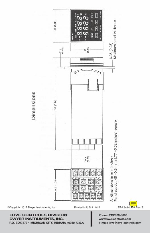
Panel Cutout: 45 mm x 45 mm (1.775” x 1.775”).Depth Behind Mounting Surface: 121.6 mm (4.79”) maximum.Weight: 220 g (8 oz).Agency Approvals: UL, C-UL E83725; CE.Front Panel Rating: IP66, (UL Type 4X).
s
949-1265:Layout 1 1/25/11 10:23 AM Page 41

Page 42
-992 RS-485 Series CommunicationsPort Compliance: EIA-485.Isolation: 500 VAC.Protocol: Lovelinks™ II.Address Range: 001H or 3FFH.Baud Rates: 300, 1200, 2400, 4800, 9600, 19.2k, 28.8k, 57.6k,Mode: Half duplex.Character: 8 bits, 1 start, 1 stop, no parity.Number of units on line/ports1: 32.Cable Lengths1: 6,000 ft (1,828 m).Termination: 120 Ohms, balanced.
-993 RS-232 Series CommunicationsPort Compliance: RS-232C.Isolation: 500 VAC.Protocol: Lovelinks™ II.Address Range: 001H or 3FFH.Baud Rates: 300, 1200, 2400, 4800, 9600, 19.2k, 28.8k, 57.6k.Mode: Half duplex.Character: 8 bits, 1 start, 1 stop, no parity.Number of units on line/ports: 1.Cable Lengths1: 25 ft (7.6 m).
-995 RS-232 Series CommunicationsPort Compliance: RS-232C.Isolation: 500 VAC.Protocol: MODBUS® RTU.Address Range: 001H or 0FFH.Baud Rates: 300, 1200, 2400, 4800, 9600, 19.2k.Mode: Half duplex.Character: 8 bits, 1 start, 1 stop, no parity.Number of units on line: 1.Cable Lengths1: 25 ft (7.6 m).
-996 RS-485 Series CommunicationsPort Compliance: EIA-485.Isolation: 500 VAC.Protocol: MODBUS® RTU.Address Range: 001H or 0FFH.Baud Rates: 300, 1200, 2400, 4800, 9600, 19.2k.Mode: Half duplex.Character: 8 bits, 1 start, 1 stop, no parity.Number of units on line/ports1: 32.Cable Lengths1: 6,000 ft (1,828 m).
1 NNo
INPU
Type
Type
Type
Type
Type
Type
Type
Type
Type
100
100
120
1000
Curr
1 T9
2 Tmwas
949-1265:Layout 1 1/25/11 10:23 AM Page 42
Page 43
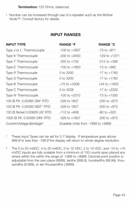
Termination: 120 Ohms, balanced.
1 Number can be increased through use of a repeater such as the Mother Node™. Consult factory for details.
INPUT RANGES
INPUT TYPE RANGE °F RANGE °C
Type J or L1 Thermocouple -100 to +1607 -73 to +871
Type K1 Thermocouple -200 to +2500 -129 to +1371
Type T1 Thermocouple -350 to +750 -212 to +398
Type E1 Thermocouple -100 to +1800 -73 to +982
Type R Thermocouple 0 to 3200 -17 to +1760
Type S Thermocouple 0 to 3200 -17 to +1760
Type B Thermocouple +75 to +3308 +24 to +1820
Type C Thermocouple 0 to 4208 -17 to +2320
Type N1 Thermocouple -100 to +2372 -73 to +1300
100 Ω Plt. 0.00385 DIN1 RTD -328 to 1607 -200 to +875
100 Ω Plt. 0.00392 NIST1 RTD -328 to 1607 -200 to +875
120 Ω Nickel 0.00628 US1 RTD -112 to +608 -80 to +320
1000 Ω Plt. 0.00385 DIN1 RTD -328 to +1607 -200 to +875
Current/Voltage/ΔVoltage2 Scalable Units from -1999 to +9999
1 These Input Types can be set for 0.1°display. If temperature goes above 999.9°or less than -199.9°the display will return to whole degree resolution.
2 The 0 to 20 mADC, 4 to 20 mADC, 0 to 10 VDC, 2 to 10 VDC, and -10 to +10mVDC inputs are fully scalable from a minimum of 100 counts span placed anywhere within the within the range of -1999 to +9999. Decimal point position is adjustable from the zero place (9999), tenths (999.9), hundredths (99.99), thou-sandths (9.999), or ten thousandths (.9999).
949-1265:Layout 1 1/25/11 10:23 AM Page 43
LOVE CONTROLS DIVISION Phone: 219/879-8000DWYER INSTRUMENTS, INC. www.love-controls.comP.O. BOX 373 • MICHIGAN CITY, INDIANA 46360, U.S.A e-mail: [email protected]
©Copyright 2012 Dwyer Instruments, Inc. Printed in U.S.A. 1/12 FR# 949-1265 Rev. 9
949-1265:Layout 1 1/25/11 10:23 AM Page 44