Embed Size (px)
Citation preview

- 1 - 210.6001.23
Instruction Manual — Series 1870E Residual Analyzer
210.6001.23 - 2 -
These instructions describe the installation, operation and maintenance of the subject equipment. Failure to strictly follow these instructions can lead to an equipment rupture that may cause significant property damage, severe personal injury and even death. If you do not understand these instructions, please call De Nora Water Technologies for clarification before commencing any work at +1 215 997 4000 and ask for a Field Service Manager. De Nora Water Technologies, Inc. reserves the rights to make engineering refinements that may not be described herein. It is the responsibility of the installer to contact De Nora Water Technologies, Inc. for information that cannot be answered specifically by these instructions.
Any customer request to alter or reduce the design safeguards incorporated into De Nora Water Technologies equipment is conditioned on the customer absolving De Nora Water Technologies from any consequences of such a decision.
De Nora Water Technologies has developed the recommended installation, operating and maintenance procedures with careful attention to safety. In addition to instruction/operating manuals, all instructions given on labels or attached tags should be followed. Regardless of these efforts, it is not possible to eliminate all hazards from the equipment or foresee every possible hazard that may occur. It is the responsibility of the installer to ensure that the recommended installation instructions are followed. It is the responsibility of the user to ensure that the recommended operating and maintenance instructions are followed. De Nora Water Technologies, Inc. cannot be responsible deviations from the recommended instructions that may result in a hazardous or unsafe condition.
De Nora Water Technologies, Inc. cannot be responsible for the overall system design of which our equipment may be an integral part of or any unauthorized modifications to the equipment made by any party other that De Nora Water Technologies, Inc.
De Nora Water Technologies, Inc. takes all reasonable precautions in packaging the equipment to prevent shipping damage. Carefully inspect each item and report damages immediately to the shipping agent involved for equipment shipped “F.O.B. Colmar” or to De Nora Water Technologies for equipment shipped “F.O.B Jobsite”. Do not install damaged equipment.
DE NORA WATER TECHNOLOGIES, COLMAR OPERATIONSCOLMAR, PENNSYLVANIA, USAIS ISO 9001: 2008 CERTIFIED
READ THE ENTIRE MANUAL BEFORE OPERATING
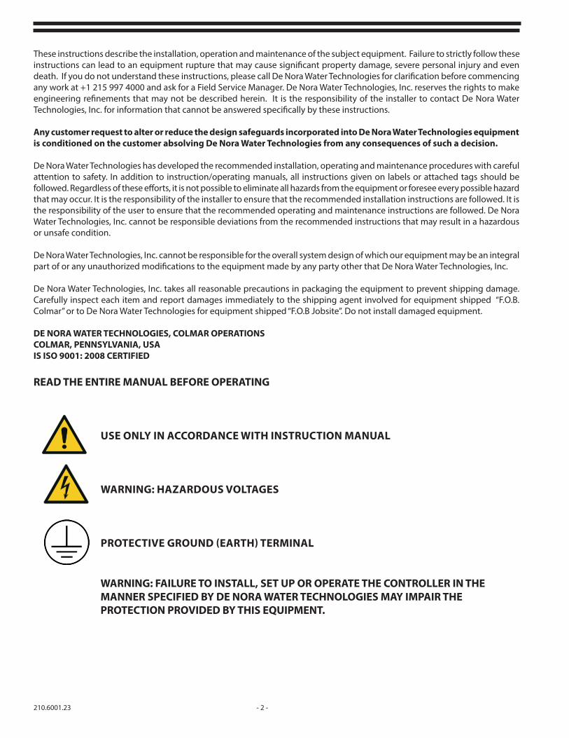
USE ONLY IN ACCORDANCE WITH INSTRUCTION MANUAL
WARNING: HAZARDOUS VOLTAGES
PROTECTIVE GROUND (EARTH) TERMINAL
WARNING: FAILURE TO INSTALL, SET UP OR OPERATE THE CONTROLLER IN THE MANNER SPECIFIED BY DE NORA WATER TECHNOLOGIES MAY IMPAIR THE PROTECTION PROVIDED BY THIS EQUIPMENT.
- 3 - 210.6001.23
Table of ContentsSAFETY . . . . . . . . . . . . . . . . . . . . . . . . . . . . . . . . . . . . . . . . . . . . . . . . . . . . . . . . . . . . . . . . . . . . . . . . . . . . . . . . . . . . . . . . . . . . . . . . . . . . . . . . 21 INTRODUCTION . . . . . . . . . . . . . . . . . . . . . . . . . . . . . . . . . . . . . . . . . . . . . . . . . . . . . . . . . . . . . . . . . . . . . . . . . . . . . . . . . . . . . . . . . . 5
1.1 General Description . . . . . . . . . . . . . . . . . . . . . . . . . . . . . . . . . . . . . . . . . . . . . . . . . . . . . . . . . . . . . . . . . . . . . . . . . . . . . . . . . . . . . . . . . 51.2 Specification . . . . . . . . . . . . . . . . . . . . . . . . . . . . . . . . . . . . . . . . . . . . . . . . . . . . . . . . . . . . . . . . . . . . . . . . . . . . . . . . . . . . . . . . . . . . . . . . 51.3 Principle of Operation . . . . . . . . . . . . . . . . . . . . . . . . . . . . . . . . . . . . . . . . . . . . . . . . . . . . . . . . . . . . . . . . . . . . . . . . . . . . . . . . . . . . . . . 61.4 EMC Testing. . . . . . . . . . . . . . . . . . . . . . . . . . . . . . . . . . . . . . . . . . . . . . . . . . . . . . . . . . . . . . . . . . . . . . . . . . . . . . . . . . . . . . . . . . . . . . . . . 6 1.5 Reagent Feed System . . . . . . . . . . . . . . . . . . . . . . . . . . . . . . . . . . . . . . . . . . . . . . . . . . . . . . . . . . . . . . . . . . . . . . . . . . . . . . . . . . . . . . . 71.6 Chlorine Chemistry . . . . . . . . . . . . . . . . . . . . . . . . . . . . . . . . . . . . . . . . . . . . . . . . . . . . . . . . . . . . . . . . . . . . . . . . . . . . . . . . . . . . . . . . . 71.7 Galvanic Cell Theory . . . . . . . . . . . . . . . . . . . . . . . . . . . . . . . . . . . . . . . . . . . . . . . . . . . . . . . . . . . . . . . . . . . . . . . . . . . . . . . . . . . . . . . . 8
2 INSTALLATION . . . . . . . . . . . . . . . . . . . . . . . . . . . . . . . . . . . . . . . . . . . . . . . . . . . . . . . . . . . . . . . . . . . . . . . . . . . . . . . . . . . . . . . . . . .112.1 General . . . . . . . . . . . . . . . . . . . . . . . . . . . . . . . . . . . . . . . . . . . . . . . . . . . . . . . . . . . . . . . . . . . . . . . . . . . . . . . . . . . . . . . . . . . . . . . . . . 132.2 Mounting . . . . . . . . . . . . . . . . . . . . . . . . . . . . . . . . . . . . . . . . . . . . . . . . . . . . . . . . . . . . . . . . . . . . . . . . . . . . . . . . . . . . . . . . . . . . . . . . . . 152.3 Hydraulic Connections . . . . . . . . . . . . . . . . . . . . . . . . . . . . . . . . . . . . . . . . . . . . . . . . . . . . . . . . . . . . . . . . . . . . . . . . . . . . . . . . . . . . . 162.4 Electrical 172.5 Set Points . . . . . . . . . . . . . . . . . . . . . . . . . . . . . . . . . . . . . . . . . . . . . . . . . . . . . . . . . . . . . . . . . . . . . . . . . . . . . . . . . . . . . . . . . . . . . . . . . . 18
3 START-UP . . . . . . . . . . . . . . . . . . . . . . . . . . . . . . . . . . . . . . . . . . . . . . . . . . . . . . . . . . . . . . . . . . . . . . . . . . . . . . . . . . . . . . . . . . . . . . .203.1 Range Selection. . . . . . . . . . . . . . . . . . . . . . . . . . . . . . . . . . . . . . . . . . . . . . . . . . . . . . . . . . . . . . . . . . . . . . . . . . . . . . . . . . . . . . . . . . . . 203.2 Measuring Chlorine (free) and Iodine . . . . . . . . . . . . . . . . . . . . . . . . . . . . . . . . . . . . . . . . . . . . . . . . . . . . . . . . . . . . . . . . . . . . . . . 203.3 Measuring Chlorine (total), Bromine Chloride, Bromine . . . . . . . . . . . . . . . . . . . . . . . . . . . . . . . . . . . . . . . . . . . . . . . . . . . . . . 233.4 Measuring Chlorine Dioxide in the Presence of Chlorine . . . . . . . . . . . . . . . . . . . . . . . . . . . . . . . . . . . . . . . . . . . . . . . . . . . . . 273.5 Conditioning the Analyzer . . . . . . . . . . . . . . . . . . . . . . . . . . . . . . . . . . . . . . . . . . . . . . . . . . . . . . . . . . . . . . . . . . . . . . . . . . . . . . . . . . 28
4 SERVICE . . . . . . . . . . . . . . . . . . . . . . . . . . . . . . . . . . . . . . . . . . . . . . . . . . . . . . . . . . . . . . . . . . . . . . . . . . . . . . . . . . . . . . . . . . . . . . . . .294.1 Cleaning . . . . . . . . . . . . . . . . . . . . . . . . . . . . . . . . . . . . . . . . . . . . . . . . . . . . . . . . . . . . . . . . . . . . . . . . . . . . . . . . . . . . . . . . . . . . . . . . . . 294.2 Reagent Valve (Analyzers with Reagent Bottle) . . . . . . . . . . . . . . . . . . . . . . . . . . . . . . . . . . . . . . . . . . . . . . . . . . . . . . . . . . . . . . 304.3 Gold Electrode . . . . . . . . . . . . . . . . . . . . . . . . . . . . . . . . . . . . . . . . . . . . . . . . . . . . . . . . . . . . . . . . . . . . . . . . . . . . . . . . . . . . . . . . . . . . . 314.4 Copper Cell . . . . . . . . . . . . . . . . . . . . . . . . . . . . . . . . . . . . . . . . . . . . . . . . . . . . . . . . . . . . . . . . . . . . . . . . . . . . . . . . . . . . . . . . . . . . . . . . 324.5 Motor/Striker Assembly . . . . . . . . . . . . . . . . . . . . . . . . . . . . . . . . . . . . . . . . . . . . . . . . . . . . . . . . . . . . . . . . . . . . . . . . . . . . . . . . . . . . 324.6 Thermistor . . . . . . . . . . . . . . . . . . . . . . . . . . . . . . . . . . . . . . . . . . . . . . . . . . . . . . . . . . . . . . . . . . . . . . . . . . . . . . . . . . . . . . . . . . . . . . . . . 334.7 Calibration . . . . . . . . . . . . . . . . . . . . . . . . . . . . . . . . . . . . . . . . . . . . . . . . . . . . . . . . . . . . . . . . . . . . . . . . . . . . . . . . . . . . . . . . . . . . . . . . . 35 4.7.1 Chlorine Residual Analyzer . . . . . . . . . . . . . . . . . . . . . . . . . . . . . . . . . . . . . . . . . . . . . . . . . . . . . . . . . . . . . . . . . . . . . . . 354.8 Motor . . . . . . . . . . . . . . . . . . . . . . . . . . . . . . . . . . . . . . . . . . . . . . . . . . . . . . . . . . . . . . . . . . . . . . . . . . . . . . . . . . . . . . . . . . . . . . . . . . . . . 38 4.9 Recommended Preventive Maintenance . . . . . . . . . . . . . . . . . . . . . . . . . . . . . . . . . . . . . . . . . . . . . . . . . . . . . . . . . . . . . . . . . . . . 384.10 Purging Circuit . . . . . . . . . . . . . . . . . . . . . . . . . . . . . . . . . . . . . . . . . . . . . . . . . . . . . . . . . . . . . . . . . . . . . . . . . . . . . . . . . . . . . . . . . . . . . 39 4.11 Peristaltic Tubing Replacement . . . . . . . . . . . . . . . . . . . . . . . . . . . . . . . . . . . . . . . . . . . . . . . . . . . . . . . . . . . . . . . . . . . . . . . . . . . . . 41
5 ACCESSORIES AND RECOMMENDED SPARE PARTS . . . . . . . . . . . . . . . . . . . . . . . . . . . . . . . . . . . . . . . . . . . . . . . . . . . . . . . . 426 TROUBLE SHOOTING CHART . . . . . . . . . . . . . . . . . . . . . . . . . . . . . . . . . . . . . . . . . . . . . . . . . . . . . . . . . . . . . . . . . . . . . . . . . . . . . 43 6.1 Interferences of Free Chlorine Analyzer Measurements . . . . . . . . . . . . . . . . . . . . . . . . . . . . . . . . . . . . . . . . . . . . . . . . . . . . . . 44
FIGURES 1 Analyzer Flow Diagram . . . . . . . . . . . . . . . . . . . . . . . . . . . . . . . . . . . . . . . . . . . . . . . . . . . . . . . . . . . . . . . . . . . . . . . . . . . . 6 2 Dissociation Curve . . . . . . . . . . . . . . . . . . . . . . . . . . . . . . . . . . . . . . . . . . . . . . . . . . . . . . . . . . . . . . . . . . . . . . . . . . . . . . . . 7 3 Wall Panel Mounting Dimensions . . . . . . . . . . . . . . . . . . . . . . . . . . . . . . . . . . . . . . . . . . . . . . . . . . . . . . . . . . . . . . . . . 10 4A Floor Cabinet Mounting Residual Analyzer Dimensions . . . . . . . . . . . . . . . . . . . . . . . . . . . . . . . . . . . . . . . . . . . . 11 4B Wall Cabinet Mounted Residual Analyzer Dimensions. . . . . . . . . . . . . . . . . . . . . . . . . . . . . . . . . . . . . . . . . . . . . . 12 5 Sample Line Taps . . . . . . . . . . . . . . . . . . . . . . . . . . . . . . . . . . . . . . . . . . . . . . . . . . . . . . . . . . . . . . . . . . . . . . . . . . . . . . . . . 13 6 Plumbing Configuration . . . . . . . . . . . . . . . . . . . . . . . . . . . . . . . . . . . . . . . . . . . . . . . . . . . . . . . . . . . . . . . . . . . . . . . . . . 14 7 Wiring Diagram . . . . . . . . . . . . . . . . . . . . . . . . . . . . . . . . . . . . . . . . . . . . . . . . . . . . . . . . . . . . . . . . . . . . . . . . . . . . . . . . . . 15 8 High/Low Latching Alarms . . . . . . . . . . . . . . . . . . . . . . . . . . . . . . . . . . . . . . . . . . . . . . . . . . . . . . . . . . . . . . . . . . . . . . . . 16 9 220/240 VAC Pump Module Power Connections . . . . . . . . . . . . . . . . . . . . . . . . . . . . . . . . . . . . . . . . . . . . . . . . . . . 18 10 Carbon Dioxide Inlet Fitting - Analyzer Without Reagent Bottle . . . . . . . . . . . . . . . . . . . . . . . . . . . . . . . . . . . . 21 11 Carbon Dioxide Regulator Assembly Installation . . . . . . . . . . . . . . . . . . . . . . . . . . . . . . . . . . . . . . . . . . . . . . . . . . . 22 12 Carbon Dioxide Inlet Fitting - Analyzer With Reagent Bottle . . . . . . . . . . . . . . . . . . . . . . . . . . . . . . . . . . . . . . . . 27 13 Overflow Weir and Filter Screen . . . . . . . . . . . . . . . . . . . . . . . . . . . . . . . . . . . . . . . . . . . . . . . . . . . . . . . . . . . . . . . . . . . 29 14 Flushing the Analyzer . . . . . . . . . . . . . . . . . . . . . . . . . . . . . . . . . . . . . . . . . . . . . . . . . . . . . . . . . . . . . . . . . . . . . . . . . . . . 29 15 Reagent Bottle Removal . . . . . . . . . . . . . . . . . . . . . . . . . . . . . . . . . . . . . . . . . . . . . . . . . . . . . . . . . . . . . . . . . . . . . . . . . . 30 16 Adapter Assembly . . . . . . . . . . . . . . . . . . . . . . . . . . . . . . . . . . . . . . . . . . . . . . . . . . . . . . . . . . . . . . . . . . . . . . . . . . . . . . . . 30 17 Reagent Valve Components. . . . . . . . . . . . . . . . . . . . . . . . . . . . . . . . . . . . . . . . . . . . . . . . . . . . . . . . . . . . . . . . . . . . . . . 31
210.6001.23 - 4 -
18 Gold Electrode Assembly . . . . . . . . . . . . . . . . . . . . . . . . . . . . . . . . . . . . . . . . . . . . . . . . . . . . . . . . . . . . . . . . . . . . . . . . . . . . . . . . . . . 3119 Motor Striker Assembly . . . . . . . . . . . . . . . . . . . . . . . . . . . . . . . . . . . . . . . . . . . . . . . . . . . . . . . . . . . . . . . . . . . . . . . . . . . . . . . . . . . . 3320 Internal Wiring Diagram . . . . . . . . . . . . . . . . . . . . . . . . . . . . . . . . . . . . . . . . . . . . . . . . . . . . . . . . . . . . . . . . . . . . . . . . . . . . . . . . . . . . 3421 Printed Circuit Board . . . . . . . . . . . . . . . . . . . . . . . . . . . . . . . . . . . . . . . . . . . . . . . . . . . . . . . . . . . . . . . . . . . . . . . . . . . . . . . . . . . . . . . 3722 Purging Circuit . . . . . . . . . . . . . . . . . . . . . . . . . . . . . . . . . . . . . . . . . . . . . . . . . . . . . . . . . . . . . . . . . . . . . . . . . . . . . . . . . . . . . . . . . . . . . 4023 Peristaltic Tube Replacement . . . . . . . . . . . . . . . . . . . . . . . . . . . . . . . . . . . . . . . . . . . . . . . . . . . . . . . . . . . . . . . . . . . . . . . . . . . . . . . 4124 Recorder 4225 Analyzer With Flushing Y-Strainer . . . . . . . . . . . . . . . . . . . . . . . . . . . . . . . . . . . . . . . . . . . . . . . . . . . . . . . . . . . . . . . . . . . . . . . . . . . 42

- 5 - 210.6001.23
1 INTRODUCTION
1.1 General DescriptionThe Series 1870E Residual Analyzer/Indicator/Transmitter is an amperometric instrument designed to continuously analyze residual levels of free or total chlorine, chlorine dioxide and other oxidants in water, wastewater or other process water applications.
1.2 SpecificationsInstrument Range: 0-0.1, 0-0.2, 0-0.3, 0-0.5, 0-1, 0-2, 0-3, 0-5, 0- 10, 0-20 mg/l, field selectable without recalibration
The amperometric analyzer is EPA approved for on-line chlorine residual monitoring in drinking water.
Analyzer Location: As close as possible to the sample point to reduce sampling dead time
Display Resolution: 0.001 mg/l for 0-2 mg/l range and below 0.01 mg/l for 0-3, 0-5, 0-10, 0-20 mg/l ranges
Power Requirements: 100/120 Vac, 50/60 Hz, or 220/240 Vac, 50/60 Hz, single phase
Power Consumption: 16 VA
Output Signal: 4-20 mAdc or 0-20 mAdc, isolated into 800 ohms maximum, or 0-50 mVdc
Relay Contacts: 10 amps @120 Vac, resistive load,
10 amps @24 Vdc, resistive load
5 amps @240 Vac, resistive load
Sample Flow: 150 ml/minute
Sample Pressure: 5 psig (0.3 bar) maximum at inlet point
Sample Supply: Continuous. Where sample interruption may be required, provisions must be made to keep the electrodes wet with fresh water.
Speed of Response: 4 seconds from sample entry to display indication. 90% of full scale within 1 1/2 to 2 minutes.
Ambient Temperature: 32° to 120° F (0° to 50° C)
Sample Temperature Range: 32° to 120° F (0° to 50° C)
Sample: Samples containing high concentrations of metal ions or certain corrosion inhibitors may affect
analyzer operation.
Electrode: Cathode: Gold
Anode: Copper
Indicator: 3-1/2 digit, LCD display in milligrams per liter (mg/l)
Accuracy: 0.003 mg/l or ±1% of range, whichever is larger. (See Sample Limitations)
Sensitivity: 0.001 mg/l (1 ppb)
Controllability: Better than 0.01 mg/l or 2% of range, whichever is larger
210.6001.23 - 6 -
Electronics Enclosure: NEMA 4X
Reagent Requirements:Residual Measurement ........................................................................................................................................................... Reagent RequirementsChlorine (free) .................................................................................................................................................................................pH buffer or CO2 gasChlorine (total) ..................................................................................................................................pH buffer or CO2 gas and potassium iodideChlorine Dioxide ..........................................................................................................................................................................pH buffer and glycineBromine Chloride ............................................................................................................................. pH buffer or CO2 gas and Potassium Iodide Bromine ............................................................................................................................................... pH buffer or CO2 gas and Potassium IodideIodine .................................................................................................................................................................................................pH buffer or CO2 gas
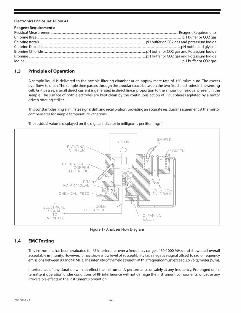
1.3 Principle of Operation
A sample liquid is delivered to the sample filtering chamber at an approximate rate of 150 ml/minute. The excess overflows to drain. The sample then passes through the annular space between the two fixed electrodes in the sensing cell. As it passes, a small direct current is generated in direct linear proportion to the amount of residual present in the sample. The surface of both electrodes are kept clean by the continuous action of PVC spheres agitated by a motor driven rotating striker.
This constant cleaning eliminates signal drift and recalibration, providing an accurate residual measurement. A thermistor compensates for sample temperature variations.
The residual value is displayed on the digital indicator in milligrams per liter (mg/l).
Figure 1 - Analyzer Flow Diagram
1.4 EMC Testing
This instrument has been evaluated for RF interference over a frequency range of 80-1000 MHz, and showed all overall acceptable immunity. However, it may show a low level of susceptibility (as a negative signal offset) to radio frequency emissions between 80 and 90 MHz. The intensity of the field strength at this frequency must exceed 2.5 Volts/meter (V/m).
Interference of any duration will not effect the instrument’s performance unsafely at any frequency. Prolonged or in-termittent operation under conditions of RF interference will not damage the instrument components, or cause any irreversible effects in the instrument’s operation.

- 7 - 210.6001.23
1.5 Reagent Feed System
Reagents are fed into the sensing cell to adjust pH and to permit measurement. The sample pH is adjusted by the buffer to a range of 4.0 to 4.5 pH. When CO2 is used as a buffer, the pH will be lowered to a range of 5.5 or 6.0 pH. The addition of potassium iodide, when used, reacts to liberate free iodine in proportion to the total chlorine and provides a means of measurement.
NOTE: The buffer feed system is designed to feed enough buffer for water which is difficult to buffer. If your sample water is easily buffered it is possible to dilute the buffer with distilled water in order to save chemical costs. Care must be taken when diluting the buffer not to dilute so much that the pH in the sample cell rises above 5.0. This is best done by gradually diluting the buffer a little more each time the reagent bottle is refilled until the pH in the cell rises to 4.8.
1.6 Chlorine Chemistry
As chlorine dissolves in water, hypochlorous acid (HOCl) and hydrochloric acid (HCl) are formed according to the following equation:
Cl2 + H2O « HOCl + HCl
Hypochlorous acid may be formed with the addition of hypochlorite [e.g. sodium hypochlorite (NaOCl) or calcium hypochlorite (Ca(OCl)2)] to water.
NaOCl + H2O « HOCl + Na+ + OH-
Ca(OCl)2 + 2H2O « 2HOCl + Ca++ + 2OH-
Hypochlorous acid is a weak acid, only partially dissociating into hydrogen and hypochlorite ions.
HOCl « H+ + OCl-
The degree of dissociation (or ionization) of hypochlorous acid is affected by pH and temperature. With decreasing pH, the degree of dissociation of hypochlorous acid decreases. Below a pH of 5.0, the dissociation of hypochlorous acid is virtually 0%, regardless of temperature. As temperature increases or decreases, the dissociation curve shifts along the pH axis. See Figure 2.
The sum of hypochlorous acid and hypochlorite ion in solution is called “free available chlorine".
If ammonia-nitrogen is present in water that is being chlorinated, further reactions can occur between ammonia-nitrogen and hypochlorous acid to form chloramine compounds. Chloramines are called “combined available chlorine”.
Figure 2 - Dissociation Curve

210.6001.23 - 8 -
The sum of free and combined available chlorine is defined as total available chlorine.
When potassium iodide (KI) is added to a solution containing total available chlorine, all chlorine species react to form free iodine. The electrochemistry of iodine in water is similar to chlorine, and it is therefore measured by the analyzer. The following equations show the chemistry of the reaction:
Free chlorine residual:Cl + HOCl + 2KI ® I2 + 2KCl + H2O
Chloramines or combined available chlorine:3H2O + 2NH2Cl + 2KI ® 2KCl + I2 + 2NH4OH + ½O2
The reaction of available chlorine with KI is also the basis of the iodometric method of chlorine analysis.
1.7 Galvanic Cell Theory
Water, in pure form, is relatively nonconductive, but addition of an ionizing species (e.g. salt) allows current to pass. The greater the concentration of ions in solution, the greater the conductance of the solution.
If two electrodes are immersed in an ion containing solution, a chemical species capable of being reduced (gaining electrons) can move toward the cathode where electrons are transferred from the cathode to the reducible species, resulting in a cathodic current.
At the same time, an oxidation reaction (where an oxidizable species loses electrons) occurs at the anode. Electrons are then transferred to the anode, producing an anodic current.
As the reaction occurs at the cathode, the concentration of the reducible species at the cathode drops. In response to the resultant concentration gradient created, more of the reducible species moves toward the cathode. This is referred to as diffusion. The speed of movement of the reducible species toward the cathode is called the rate of arrival.
The rate that the reducible species arrives at the cathode is dependent on its concentration. As the concentration increases the diffusion to the cathode increases, which increases the current.
The current is also affected by temperature. With elevated temperatures, diffusion increases. Most systems compensate for temperature in some fashion.
If the electrodes are made of two (selected) dissimilar metals and the proper conditions exist with regard to solution composition, current can be produced by simply connecting (shorting) the electrodes. This type of cell is called a galvanic cell.
In a galvanic cell, a change in concentration is detected by measuring the change in current flowing through the cell. The cell current responds proportionally to changes in concentration.
The cathode in the galvanic cell used in the 1870E Chlorine Analyzer is gold. When hypochlorous acid (or hypochlorite ion) is present in solution, electrons are exchanged at the cathode surface and chloride ions are produced.
HOCl + 2e- « Cl- + OH-
The anode is copper. As electrons are exchanged, an oxide product remains on the anode. Because of this, an abrasion mechanism (constant stirring of cleaning spheres) is incorporated to strip the oxide product off the metal surface. Since copper is consumed in the process, the term sacrificial anode is applied to the copper electrode.

- 9 - 210.6001.23
Current flow in the amperometric cell is affected by changes in pH. The cell current is most stable between 4 and 4.5 pH, therefore, a pH buffering solution is used in the cell to stabilize the cell current.
Temperature compensation circuitry is employed to counter the affects of diffusion and other factors that are affected by temperature.
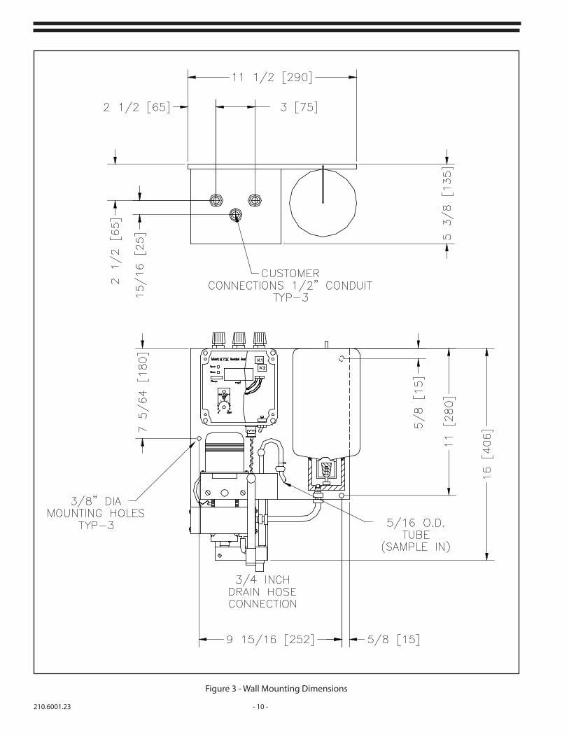
210.6001.23 - 10 -
Figure 3 - Wall Mounting Dimensions
- 11 - 210.6001.23
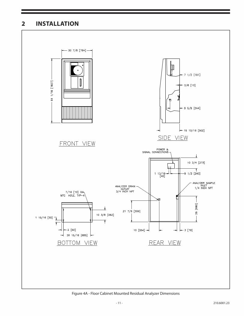
Figure 4A - Floor Cabinet Mounted Residual Analyzer Dimensions
2 INSTALLATION

210.6001.23 - 12 -
Figure 4B - Wall Cabinet Mounted Residual Analyzer Dimensions

- 13 - 210.6001.23
Figure 5 - Sample Line Taps
2.1 General
The Series 1870E Residual Analyzer is designed for a multitude of applications. This instrument will provide unparalleled accuracy for drinking water, wastewater, cooling water, beverage, industrial effluent, RO membrane, and process control applications or any application where highly accurate chlorine detection and control are necessary. The tasks described in this section require that individuals be technically knowledgeable and aware of proper safety procedures. Individuals must adhere to all applicable electrical and plumbing codes.
2.1.1 Unpacking
Remove the instrument from its packing container and carefully inspect each item and report damages immediately. Be sure that the following items were included in the carton:
Series 1870E Chlorine Residual Analyzer (receiver, wet end on a backboard and reagent bottle)
Instruction Manual
2.1.2 Environmental Requirements
The instrument is designed for general duty indoor installation. Outdoor installation is possible if the instrument is shielded from dripping water and not mounted in direct sunlight. Ambient temperatures should range from 32°F to 140°F (0°C to 60°C) with sample temperatures from 32°F to 120°F (0°C to 50°C).

210.6001.23 - 14 -
Figure 6 - Plumbing Configuration

- 15 - 210.6001.23
2.1.3 LocationIn order to obtain optimum performance from the Series 1870E Residual Analyzer, selection of a good, representative sampling point is critical. If a sampling point is too close to the chlorine feed, inadequate mixing, or incomplete chlorine/sample reaction may occur. The sampling point should be where the sample and chlorine is reacted and mixed thoroughly so the analyzer is indicating the representative residual chlorine being carried throughout the water system.
All residual analyzers should be located as close to the sampling point as possible to reduce sample dead time. Sampling lines should be run with small diameter tubing to minimize the lag time.
The electronic enclosures are designed to protect the electronics from typical conditions in water/wastewater treatment or industrial facilities.
2.2 Mounting
2.2.1 Wall Panel
Dimensional drawings are given to aid installation and to determine the position of mounting holes. Figure 3.
a. Remove the reagent bottle, if supplied, to gain access to the three (3) mounting holes. The clip securing the reagent bottle should be lifted and rotated 90° to release the bottle.
Figure 7 - Wiring Diagram
ALARM CONTACTS
WARNING: CHECK LINE VOLTAGE SELECTOR SWITCH FOR PROPER SETTING BEFORE APPLYING POWER.IF NECESSARY, REMOVE THE PLASTIC STRAP ON THE SWITCH.

210.6001.23 - 16 -
b. Position the analyzer panel on a wall at eye level and as close as possible to the sample.
2.2.2 Cabinet Mounting
a. All hydraulic and electrical connections are made at the cabinet using bulkhead fittings and an electric junction box.
b. Refer to the Cabinet Instruction Manual for installation details.
2.3 Hydraulic Connections (Wall Panel Only)
2.3.1 Procedure
a. Connect a length of 3/4" drain hose to the drain outlet on the analyzer. Secure with a 3/4" hose clamp. Route the hose to maintain a gravity fed drain (downward slope).
b. Connect one end of the 5/16" sample supply tubing to the source using the 1/4" NPT connector. Route the tubing to the sample filter chamber through the two (2) tubing holders on the analyzer panel. Position the end of the tubing between the filter chamber and below the top of the overflow weir (See Figure 12. Note the proper position of the overflow weir.) Do not direct water flow to the center of the overflow weir. The maximum desired pressure for the flow is about 5 psig (0.3 bar). The sample tubing is rated to 55 psig (3.8 bar).
Figure 8 - High/Low Latching Alarms

- 17 - 210.6001.23
2.3.2 Sample Line Taps
Sample line taps into larger pipes should be installed to minimize the chances of air bubbles or sediment entering the analyzer. A tap should project into the center of the line. Figure 5.
2.3.3 Sample Flow
A typical installation may require a sample pump if the pressure is low and/or a Y-strainer to remove any particulates. There may also be a need for a pressure reducing valve if the sample pressure is too high or the sample pump needs to be regulated. Figure 6.
2.3.4 Peristaltic Buffer Pump (If equipped)
Remove the tubing assembly from the supplied 5 gallon reagent container(s). Insert the weighted end of the tubing assembly into the container and connect the other end to the barb on the inlet side of the peristaltic pump.
2.4 Electrical
NOTE: All wiring must comply with applicable local and national electrical codes.
2.4.1 Wall Panel Mounted Conduit Connections
a. Remove four (4) screws securing the clear cover and remove the cover.
b. Remove four (4) screws securing the face plate. Remove the face plate.
c. Set the line voltage Selector Switch to the proper voltage. If necessary, remove the plastic strap on the switch. See Figures 7 and 20.
d. Route the power line from the analyzer to the power supply through the top opening.
e. Connect the power wiring to the L1, N, and terminals. See Figure 7.
f. Connect current output and alarm contacts, NOTE: Do not run line voltage and low level signal voltage in the same conduit. See Figure 7.
g. Replace face plate and clear cover.
NOTE: For electrical connections in cabinet mounted analyzers, refer to CabinetInstruction Manual.
2.4.2 Buffer Feeder Mains Power
CAUTIONELECTRICAL CONNECTION SHOULD ONLY BE
UNDERTAKEN BY SUITABLY QUALIFIED PERSONNEL.
The buffer feeder pump requires a single-phase power source. The buffer feed motor can be wired to either a 110 VAC or 220/240 VAC supply as appropriate.
110 VAC models are supplied with a pre-wired 3-pin power cable and plug. All other models require a cable and plug to be fitted before use.
The voltage to ground from either pole of the power source must not exceed the maximum rated operating voltage, 130 for 110VAC supply or 264 VAC for the 220-240VAC supply. Before making connection to the power source, determine that the voltage of the power source is correct. The power source must have a fuse or circuit breaker rated no higher than 1 A, and be supplied via a suitable disconnection device i.e. a switch.

210.6001.23 - 18 -
All 220/240 VAC: To fit a power cable to the buffer feed pump, unscrew the 4 retaining screws on the buffer pump assembly. Locate the 3 wires attached to the buffer feed motor and identify the two black leads as shown below. Attach a suitable power lead to the motor leads as local regulations permit. Connect the power lead earth ground to the side case of the motor as shown below, pass the power lead through the cable gland and tighten the gland, this ensures a waterproof and robust seal around the power lead.
Reassemble the enclosure ensuring no wires or leads are trapped.
Figure 9 - 220/240VAC Pump Module power connections
2.5 Set Points
High and low set point adjustment knobs are located on the front of the unit. To set the alarm points,proceed as follows:
2.5.1 Alarm
Verify the factory-applied range sticker corresponds with the range selected. If the range is not indicated, is incorrect or missing, select the correct sticker, included with your unit, and place it on the front of the unit in the space provided. In order to establish your set points, you must know the instrument’s range.
a. Determine the high and low milligram per liter value at which you want the analyzer to alarm. To figure these percentages, use the following formula:
Alarm point range X 100 = % set point
b. Set the low set point to the percentage value for the low alarm point and the high set point to the percentage value for the high alarm point.

- 19 - 210.6001.23
2.5.2 High/Low/Latching Alarms
The high/low/latching alarms are a field mountable option. Refer to Figures 7, 8, and 21 and plug the alarm board into the J3 receptacle on the main printed circuit board. Secure with the two (2) 4-40 X 1/4" screws supplied.
The alarm module has one low alarm and one alarm which can be selected as a high, low or latching (adjust-able deadband) alarm/control by setting the jumper as shown in Figure 8. Jumper positions are located in the lower left portion of the alarm board.
Use the slot on the potentiometer to indicate approximate set point.
Relay contacts are SPDT, 10 amps at 250 Vac or 60 Vdc. Relays are de-energized during normal operation and energized during alarm conditions.
a. Operation - Latching Mode
When the incoming signal is below the LOW set point, the K1 relay will energize and remain energized until the signal increases above the HIGH K1 set point. The relay will de-energize and remain off until the signal drops below the LOW set point.
When the latching mode is selected, the K1 control is used to set the HIGH drop-out point, and the LOW control is used to set the LOW pull-in point, with both controls operating the K1 relay. The LOW relay will still function and will trip at the LOW control setting.
The latching mode is used where it is desired to begin chemical feed at some low point and continue feeding until the selected higher point is reached.

210.6001.23 - 20 -
3 START-UP3.1 Range Selection (Refer to Figure 20)
Select the instrument range, per Table I, via the DIP switches and jumper plug found on the printed circuit board. Ranges can be changed by resetting the DIP switches and the decimal point jumper plug (where necessary). Zero and span recalibrations are not necessary.
For measuring chlorine, S3-4 (DIP package S3, switch number 4) switch should be OFF. For all other measurements, S3-4 should be ON. If ranges are changed, the paste on labels on the front plate must also be changed, using the labels provided.
Table I - Range Selection
3.2 Measuring Chlorine (free) and Iodine
3.2.1 ReagentsA pH buffering solution or carbon dioxide gas is required for analyzer operation. The 2-liter reagent bottle provides approximately a 1-week supply. Use of the Peristaltic Pump Feeder with the 5 gallon reagent tank can provide up to a 60 day supply of reagents. A premixed pH buffer solution (A-1806) is available from De Nora Water Technologies or the buffer solution may be prepared by mixing the chemicals.
NOTE: Never disable unit without removing the reagent bottle and flushing with clean water until all chemical is removed. Failure to use or mix buffer as outlined may void product warranty.
WARNING: Consult applicable material safety data sheets prior to handling chemicals. Buffer solution contains glacial acetic acid, which is corrosive. Avoid contact with skin and eyes and breathing of vapor. Use rubber gloves and safety glasses when handling buffer solution or changing the reagent bottle. Use only with adequate ventilation (i.e. under a fume hood). Only an acetic acid based (concentrated) pH 4 buffer should be used. The use of other buffers may cause improper analyzer operation.
3.2.2 Mixing ChemicalsIf you are not using the premixed buffer solution, then it is necessary to make a buffer solution as follows:a. Using a 1 gallon (3.8 liter) bottle, fill the bottle 1/2 full with distilled or deionized water.b. Add 920 grams sodium acetate trihydrate crystals and mix until all the crystals are dissolved.c. Add 1800 grams or 1730 ml glacial acetic acid.d. Fill bottle to the top with distilled or deionized water and shake to thoroughly mix solution. Pour into
the analyzer reagent bottle. e. The result is a buffer solution the same composition as the premixed buffer.
Rangemg/l
DIP SwitchesDecimal
Point Jumper Plug
Maximum Display
S3 S4
1 2 3 2 3 4
0-0.1 OFF ON OFF OFF ON OFF
0-0.2 ON OFF OFF OFF ON OFFO
O
O
2.00 mg/l
0-0.3 OFF OFF OFF OFF ON OFF
0-0.5 OFF OFF ON ON OFF OFF
0-1 OFF ON OFF ON OFF OFF
0-2 ON OFF OFF ON OFF OFF
0-3 OFF OFF OFF OFF OFF OFF O
O
O
20.0 mg/l0-5 OFF OFF ON ON OFF ON
0-10 OFF ON OFF ON OFF ON
0-20 ON OFF OFF ON OFF ON

- 21 - 210.6001.23
3.2.3 Buffer Preparation
3.2.3.1 Analyzers with Reagent Bottle
a. Using a 1 gallon (3.8 liter) bottle, add 2 quarts (1.9 liters) of either the premixed buffer (3.2.1) , or the prepared buffer (3.2.2).
b. Fill the bottle to the top with distilled or deionized water and shake the bottle to thoroughly mix.
c. Pour into the analyzer reagent bottle.
3.2.3.2 Analyzers with Buffer Pump
a. Fill the 5 gallon container marked Acetic Acid with Buffer. Be sure the pump suction line is at the bottom of the container when reinstalling the cap.
3.2.4 Carbon Dioxide (CO2) Gas
When using carbon dioxide gas for pH buffering, a carbon dioxide gas flow rate of 175 cubic centimeters per minute, at 1 psig is required. Install the regulated gas flow line as follows:
a. Wall Panel Mounted
Run a regulated carbon dioxide gas flow line to the inlet fitting mounted on the lower right side of the analyzer cell. (Refer to Figure 10).
b. Wall or Floor Cabinet Mounted
Run a regulated carbon dioxide gas flow line to the bulkhead connector on the inlet side of the cabinet.
c. Procedure for using A-1730-1 CO2 Regulator:
1. Turn off power and water supply to the anayzer and open all analyzer drains.
2. Mount the pressure regulator on the carbon dioxide cylinder and connect it to the diffuser assembly inlet with 3/8" tubing. (see Figure 11)
3. Restore power and water to the analyzer and check for leaks.
Figure 10 - Carbon Dioxide Inlet Fitting Analyzer Without Reagent Bottle
210.6001.23 - 22 -
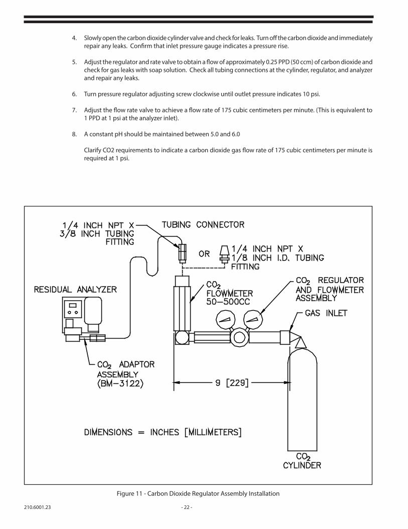
4. Slowly open the carbon dioxide cylinder valve and check for leaks. Turn off the carbon dioxide and immediately repair any leaks. Confirm that inlet pressure gauge indicates a pressure rise.
5. Adjust the regulator and rate valve to obtain a flow of approximately 0.25 PPD (50 ccm) of carbon dioxide and check for gas leaks with soap solution. Check all tubing connections at the cylinder, regulator, and analyzer and repair any leaks.
6. Turn pressure regulator adjusting screw clockwise until outlet pressure indicates 10 psi.
7. Adjust the flow rate valve to achieve a flow rate of 175 cubic centimeters per minute. (This is equivalent to 1 PPD at 1 psi at the analyzer inlet).
8. A constant pH should be maintained between 5.0 and 6.0
Clarify CO2 requirements to indicate a carbon dioxide gas flow rate of 175 cubic centimeters per minute is required at 1 psi.
Figure 11 - Carbon Dioxide Regulator Assembly Installation

- 23 - 210.6001.23
3.3 Measuring Chlorine (total), Bromine Chloride, Bromine
3.3.1 Reagents
A pH buffering solution or carbon dioxide gas, plus potassium iodide are required for analyzer operation. Only an acetic acid-based (concentrated) pH 4 buffer should be used. The use of other pH 4 buffers may cause improper analyzer operation. A premixed pH buffer solution (A-1806) is available fromDe Nora Water Technologies, or the buffer solution may be prepared by mixing chemicals.
3.3.2 Mixing Chemicals (Analyzers with Reagent Bottle)
WARNING: Consult applicable material safety data sheets prior to handling chemicals. The buffer solution contains glacial acetic acid, which is corrosive. Avoid contact with skin and eyes and breathing of vapor. Use rubber gloves when handling buffer solution or changing the reagent bottle. Use only with adequate ventilation (i.e. under a fume hood).
a. Using the analyzer reagent bottle, fill the bottle 1/2 full with distilled or deionized water.b. Add potassium iodide crystals (part number R-410, available from De Nora Water Technologies) as per the table below to the 1/2 full reagent bottle:
c. Shake until crystals are completely dissolved.
d. Add 250 grams sodium acetate trihydrate crystals and mix until all the crystals are dissolved.
e. Add 900 grams or 435 ml glacial acetic acid.
f. Fill the analyzer reagent bottle to the top with distilled or deionized water and shake again.
Potassium Iodide (KI)(grams) Analyzer Range (mg/l)
2.5 0-0.2
5.0 0-0.5
20 0-2.0
30 0-3.0
50 0-5.0
100 10
200 20
210.6001.23 - 24 -
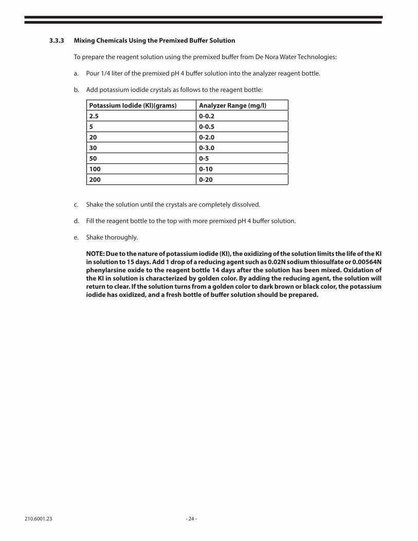
3.3.3 Mixing Chemicals Using the Premixed Buffer Solution
To prepare the reagent solution using the premixed buffer from De Nora Water Technologies:
a. Pour 1/4 liter of the premixed pH 4 buffer solution into the analyzer reagent bottle.
b. Add potassium iodide crystals as follows to the reagent bottle:
c. Shake the solution until the crystals are completely dissolved.
d. Fill the reagent bottle to the top with more premixed pH 4 buffer solution.
e. Shake thoroughly.
NOTE: Due to the nature of potassium iodide (KI), the oxidizing of the solution limits the life of the KI in solution to 15 days. Add 1 drop of a reducing agent such as 0.02N sodium thiosulfate or 0.00564N phenylarsine oxide to the reagent bottle 14 days after the solution has been mixed. Oxidation of the KI in solution is characterized by golden color. By adding the reducing agent, the solution will return to clear. If the solution turns from a golden color to dark brown or black color, the potassium iodide has oxidized, and a fresh bottle of buffer solution should be prepared.
Potassium Iodide (Kl)(grams) Analyzer Range (mg/l)
2.5 0-0.2
5 0-0.5
20 0-2.0
30 0-3.0
50 0-5
100 0-10
200 0-20

- 25 - 210.6001.23
3.3.4 Mixing Chemical ( Analyzers with Buffer Pump)
WARNING: Consult appropriate material safety data sheets prior to handling chemicals. The buffer solution contains glacial acetic acid, which is corrosive. Avoid contact with skin and eyes and breathing of vapor. Use rubber gloves when handling buffer solution or changing the reagent bottle. Use only with adequate ventilation (i.e. under a fume hood).
Reagent #1 (Acetic Acid Buffer Solution)
Acetic acid buffer, A-1806, is purchased from De Nora Water Technologies, and may be transferred to the 5-gallon container (marked Acetic Acid) provided with the analyzer. The buffer contains the proper amounts of acetic and sodium acetate. No chemical preparation is required.
Reagent #2 (Potassium Iodide and Sodium Hydroxide Solution)
1. In the 5-gallon container marked Potassium Iodide and Sodium Hydroxide (reagent #2), dissolve100 grams of sodium hydroxide pellets in four gallons (15.15 liters) of distilled or deionized water.
2. When the sodium hydroxide has cooled to ambient temperature, add the required quantity of potassium iodide (see below)
3. Mix by stirring the solution with a PVC or polyethylene rod.
Potassium Iodide Weights
3.3.4.1 Reagent consumption
Reagent consumption is approx. 20 liters in 60 days.
*Potassium Iodide weight is based on full scale Cl2 residuals. Weights may be reduced to match the expected residual values if they are normally less than the full scale value. ie: Full scale = 0-10 and typical residual value is 1.0, then use 60 grams of Potassium Iodide.
3.3.5 Carbon Dioxide Gas
When using carbon dioxide gas for pH buffering, a carbon dioxide gas flow rate of 200 cubic centimeters per minute is required at 1 psig. Install the regulated gas flow line gas follows:
a. Wall Panel Mounted - Run a regulated carbon dioxide gas flow line to the inlet fitting mounted on the lower right side of the analyzer cell. (Refer to Figure 12).
b. Wall or Floor Cabinet Mounted - Run a regulated carbon dioxide gas flow line to the bulkhead connector on the inlet side of the analyzer cabinet.
Measurement Range (mg/L) Potassium Iodide (grams)
0 – 0.25 15
0 – 0.50 300 – 1.0 600 – 2.0 1200 – 5.0 300
0 – 10.0 6000 – 20.0 1200

210.6001.23 - 26 -
c. Procedure for using A-1730-1 CO2 Regulator:
1. Turn off power and water supply to the analyzer and open all analyzer drains.
2. Mount the pressure regulator on the carbon dioxide cylinder and connect it to the diffuser assembly inlet with 3/8" tubing. (see Figure 11)
3. Restore power and water to the analyzer and check for leaks.
4. Slowly open the carbon dioxide cylinder valve and check for leaks. Turn off the carbon dioxide and immediately repair any leaks. Confirm that inlet pressure gauge indicates a pressure rise.
5. Adjust the regulator and rate valve to obtain a flow of approximately 0.25 PPD (50 ccm) of carbon dioxide and check for gas leaks with soap solution. Check all tubing connections at the cylinder, regulator, and analyzer and repair any leaks.
6. Turn pressure regulator adjusting screw clockwise until outlet pressure indicates 10 psi.
7. Adjust the flow rate valve to achieve a flow rate of 175 cubic centimeters per minute. (This is equivalent to 1 PPD at 1 psi at the analyzer inlet).
8. A constant pH should be maintained between 5.0 and 6.0
d. Using the analyzer reagent bottle, add 1 quart distilled or deionized water.
e. Add potassium iodide crystals (part number R-410, available from De Nora Water Technologies) as follows to the 1/2 full reagent bottle:
f. Shake until crystals are completely dissolved.
g Fill the reagent bottle to the top with distilled or deionized water and shake again.
Potassium Iodide (KI)(grams) Analyzer Range (mg/l)
2.5 0-0.2
5 0-0.5
20 0-2.0
30 0-3.0
50 0-5
100 0-10
200 0-20

- 27 - 210.6001.23
3.4 Measuring Chlorine Dioxide in the Presence of Chlorine
3.4.1 Reagents
A pH buffering solution or carbon dioxide gas is required for analyzer operation. In addition, glycine is required. Only an acetic acid-based (concentrated) pH 4 buffer should be used. The use of other pH 4 buffers may cause improper analyzer operation. A premixed pH buffer solution (A-1806) is available from De Nora Water Technologies, or the buffer solution may be prepared by mixing chemicals.
WARNING: Consult applicable material safety data sheet prior to handling chemicals. The buffer solution contains glacial acetic acid, which is corrosive. Avoid contact with skin and eyes and breathing of vapor. Use rubber gloves when handling buffer solution, mixing with other reagents, or changing the reagent bottle. Use only with adequate ventilation (i.e. under a fume hood).
3.4.2 Mixing Chemicals (Analyzers with Reagent Bottle)
a. Using the analyzer reagent bottle, fill the bottle 1/2 full with distilled or deionized water.
b. Add 250 grams sodium acetate trihydrate crystals and mix until all the crystals are dissolved.
c. Add 900 grams or 435 ml glacial acetic acid.
d. Add 175-200 grams of glycine crystals (glycine crystals, part number R-3513, is available from De Nora Water Technologies).
e. Fill analyzer reagent bottle to the top with distilled or deionized water and shake to thoroughly mix solution.
Figure 12 - Carbon Dioxide Inlet Fitting Analyzer With Reagent Bottle

210.6001.23 - 28 -
3.4.3 Mixing Chemicals Using Premixed Buffer Solution ( Analyzers with Reagent Bottle)
a. Add 1 liter of distilled or deionized water to a 1 gallon (3.8 liter) bottle.
b. Add 350-400 grams of glycine crystals (glycine crystals, part number R-3513, is available from De Nora Water Technologies) to 1/4 full gallon bottle.
c. Fill the 1 gallon (3.8 liter) bottle to the top with pH buffer solution (part number A-1806) and shake bottle to thoroughly mix. Make sure the glycine crystals are dissolved completely.
d. Pour into the analyzer’s reagent feed bottle.
e. Set the DIP switch S3-4 (DIP package S3, switch number 4) to the ON position.
3.5 Conditioning the Analyzer
3.5.1.1 Analyzers with Reagent Bottle
Hold filled reagent bottle upright and pull the tapered plug upward until the hole in the cap is plugged. Turn the bottle upside down and install into reagent feeder body. The weight of the reagent bottle opens the tapered plug and the bottle will rest on the O-ring on the top of the feeder body. Lift and turn the spring clip to secure the bottle.
3.5.1.2 Analyzers with Buffer Pump
Add reagents to the supplied 5 gallon containers as required. (Refer to Section 3.2)
3.5.2 Start the water sample flow of approximately 150 ml/minute (1 pint/minute). Water must be flowing over the overflow weir in the sample filter chamber to drain.
3.5.3 The sample must be supplied continuously for reliable operation. If the system requires occasional cutoff, provisions must be made to keep the electrodes wet.
3.5.4 Sampling from a pressurized source may required a pressure reducing valve to hold the flow constant. Maximum desired pressure is 5 psig (0.3 bar).
3.5.5 If sampling from wastewater, a flushing Y-strainer is necessary to prevent sample line pluggage. Other types of filter are not recommended.
3.5.6 Turn ON power to the analyzer and Peristaltic Buffer Pump if so equiped.
3.5.7 If air bubbles are present in the reagent or flow tubing, squeeze, tap, or disconnect tubing at the analyzer and flush momentarily.
3.5.8 The analyzer requires a minimum stabilization time of 24 hours. During this time, reagents must be feeding into the cell. Normal reagent feed is approximately 3/4" to 1 1/8" level change in 24 hours.
3.5.9 After stabilization, calibration may begin. See Section 4.7.

- 29 - 210.6001.23
4 SERVICE
4.1 Cleaning
Frequency of cleaning the analyzer is greatly affected by the condition of the water. By visually inspecting for dirt buildup, determine the need for cleaning. The following should be cleaned as indicated:
4.1.1 The inlet filter screen and overflow weir should be cleaned when a dirt buildup is observed or when the screen has been plugged sufficiently to stop flow. Refer to Figure 13, and lift out the overflow weir and filter screen. Hold parts under a water stream until clean and reinstall in the analyzer.
4.1.2 If the analyzer is clogged to the point where no water will pass over the overflow weir, the analyzer must be flushed. Observe below the motor or by the overflow tube directly behind the cell which drains into the block. See Figure 14 and flush as follows:
a. Turn the power switch to the OFF position.
b. Remove the flush plug in the flow tube with sample flowing, and allow to drain.
c. Install flush plug into the flow tube.
d. Repeat steps b and c as required.
e. Turn the power switch to the ON position and resume operation.
Figure 13 - Overflow Weir and Filter Screen Figure 14 - Flushing the Analyzer

210.6001.23 - 30 -
4.2 Reagent Valve (Analyzers with Reagent Bottle)
If the reagent feed has stopped and all air is removed from the tubing, the reagent valve must be cleaned. The feed rate of this valve is very small, therefore, be certain the reagent has stopped before cleaning is attempted. Check for feed by marking the reagent level on the bottle and observing the change in level over 8 hours. If the reagent level has not lowered during this period, the valve must be cleaned. Refer to Figures 15, 16, and 17 and proceed as follows:
4.2.1 Turn the power switch to the OFF position.
4.2.2 Stop sample flow.
4.2.3 Lift and rotate clip securing the reagent bottle. Raise reagent bottle approximately 2" and pull down on the valve stem until the hole in the cap is plugged. Remove reagent bottle.
4.2.4 Hold reagent bottle upright and remove cap. Place open bottle close to clear tubing connector at the adapter. Carefully unscrew connector nut releasing clear tube and drain remaining reagent into the reagent bottle. Screw cap on reagent bottle.
4.2.5 Remove flush plug to drain the unit. After the analyzer is completely drained, replace the plug.
4.2.6 Loosen the four (4) screws securing the adapter and remove the adapter and O-ring.
4.2.7 Clean out the bottom body if necessary.
4.2.8 The adapter provides mounting for the reagent valve components. This valve consists of a star wheel, bushing, pin, O-ring, spring and a screw. Loosen the screw and rotate the spring 180°. Pull up on the star wheel to release the pin from the bushing. Do NOT remove the bushing or O-ring.
Figure 15 - Reagent Bottle Removal Figure 16 - Adapter Assembly

- 31 - 210.6001.23
Clean parts under a water stream. If the 1/16" diameter holes in the star wheel are clogged, use a straight pin to remove the obstruction, being careful not to scratch mating surfaces or damage the edge of the hole. Place the star wheel and pin into the bushing. Turn the spring back 180° to apply force to the pin. Secure the screw.
4.2.9 Place the large O-ring into the groove and replace the adapter. Secure using the four (4) screws.
4.2.10 Reconnect clear tubing to connector, secure nut.
4.2.11 Invert the reagent bottle on the reservoir and secure with the clip.
4.2.12 Begin sample flow as described in Section 3
4.2.13 Turn the power switch to the ON position. If air bubbles appear in the clear reagent tubing, remove them as described in the Section 3.
4.3 Gold Electrode
Normal life of the gold electrode is three to five years. This can vary depending upon the chemical residual and the quality of the water. The gold electrode should appear clean and shiny.
NOTE: The gold electrode assembly contains 200 - 3/16" diameter PVC spheres within the top body of the analyzer. When this assembly is withdrawn, these spheres will drop out. Refer to Figures 18 and 19. Place a cup or other container under the assembly to catch the spheres.
4.3.1 Refer to the Service 4.2.1-4.2.7. Remove the adapter and all reagent.
4.3.2 Disconnect the wire from the gold electrode assembly.
4.3.3 While holding a container under the analyzer, unscrew the gold electrode by hand. As the assembly is withdrawn the spheres will begin dropping out. Hold a container below until all the spheres are removed. Remove the large O-ring on the electrode assembly.
4.3.4 Inspect the condition of the gold electrode. Clean and polish with water and a clean cloth. If the electrode is damaged, it must be replaced.
Figure 17 - Reagent Valve Components Figure 18 - Gold Electrode Assembly

210.6001.23 - 32 -
4.3.4 Place the large O-ring in the groove on the new electrode assembly and screw the assembly into the bottom body, by hand, until snug.
4.3.5 Reconnect the wire to the gold electrode assembly.
4.3.6 Remove the plug located in the analyzer top body. Deposit all spheres through the hole provided, and replace the plug.
4.3.7 After depositing spheres, rotate the motor/striker assembly by hand, checking for rubbing, The striker can be observed below the motor. If the striker is not rotating, refer to Section 4.5. Turn the power switch to the ON position.
4.4 Copper Cell
NOTE: The copper cell contains 200 3/16" PVC spheres. When this assembly is removed, the spheres will fall. Place a cup or other container under the assembly to catch the spheres.
4.4.1 Turn the power switch to the OFF position.
4.4.2 Stop the sample flow to the analyzer.
4.4.3 Remove the drain plug and drain the water from the sediment trap.
4.4.4 Remove the gold electrode assembly. Refer to Service section 4.3.
4.4.5 Take care to catch the loose PVC spheres. Any buildup in the cell can be removed with a plastic scouring pad or similar mild abrasive.
4.4.6 After cleaning, reinstall the cell ensuring the cell gasket is in place.
4.4.7 Remove the plug located in the front of the analyzer’s top body and deposit all PVC spheres through the hole. Replace the plug.
4.4.8 After depositing the spheres, rotate the motor/striker assembly, by hand, checking for smooth movement. If the striker is not rotating, refer to Section 4.5. Turn the power switch to the ON position.
4.5 Motor/Striker Assembly
Replacing the motor or striker assembly can be performed easily if the main analyzer is removed from the panel and taken to a table or flat surface.
4.5.1 Disconnect power to the analyzer motor. Remove motor wires from terminals M1, M2, M3 and G. See Figures 19 and 20.
4.5.2 Disconnect signal wires from copper and gold electrodes.
4.5.3 Remove reagent from the feeder body and reagent tubing from the valve adapter. Unscrew two 1/4" diameter screws holding the main assembly to the panel. Place the main assembly on the table.
4.5.4 With the main assembly upright, remove the three (3) screws holding the motor plate to the top body. Lift the motor straight up and out of the top body.
4.5.5 Invert analyzer assembly and empty the spheres into a container. Remove the valve adapter. The main assembly is now disassembled as far as required.

- 33 - 210.6001.23
4.5.6. If the motor is to be replaced, remove the striker and rubber boot from the motor shaft. Install the boot on the new motor and striker after turning the center set screws out approximately two (2) turns. Refer to Figure 19.
4.5.7 Turn the side set screw in the striker until it contacts the motor shaft. The striker should slide onto the motor shaft when force is applied.
4.5.8 Fit the striker on to the motor so a 1/4" space is between the top of the striker and the motor plate. Insert the motor/striker assembly into the main analyzer assembly by pushing on the motor until the motor plate is seated on the top body.
4.5.9 Carefully remove the motor/striker from the main assembly. Lightly tighten the side set screw in the striker. Turn the center set screw until contact is made with the motor shaft, then back out the center set screw 1/8 to 1/4 turn. Loosen the side striker set screw and push up on the motor shaft. Re-tighten the side set screw snugly. Reinstall the motor/striker assembly with the three (3) motor screws.
4.5.10 Rotate the motor/striker assembly by hand checking for drag or rubbing.
4.5.11 Insert the 200 spheres and rotate motor/striker again, feeling for drag or rough spots. If drag is present, repeat steps 4.5.7 through 4.5.10 to adjust the striker.
4.5.12 Reassemble by reversing steps 4.5.1, 4.5.2, and 4.5.3.
4.6 Thermistor
Failure to the thermistor will appear as an excessively high or low signal. Proceed as follows for testing and replacement. Refer to Figure 19.
4.6.1 Turn the power switch to the OFF position.
Figure 19 - Motor Striker Assembly

210.6001.23 - 34 -
4.6.2 Remove the two (2) thermistor wires from terminals T1 and T2, and remove the thermistor.
4.6.3 Connect an ohm meter to the thermistor wires. If the ohm meter shows a stable resistance reading between 2k and 4k, the thermistor is not defective. If the ohm meter shows zero ohms or goes into infinity, the thermistor is defective and must be replaced. Recalibration is required. See Calibration section 4.7.
Figure 20 - Internal Wiring Diagram
GRY
V
O
G
Y
BN
BL
LOWLED
-
+
BK
O
G
BN
Y
BL
-
R +
LEDHIGH
DIS
PLAY
CO
NN
EC
TOR
S (O
N P
.C. B
OA
RD
)
O G BN Y BL BL BN O Y G
DISPLAY REAR VIEW
FRONT PANEL DISPLAY CONNECTIONS
O
W
BK
G
R
ZER
O/S
PA
N C
ON
NEC
TOR
(ON
P.C
. BO
ARD
)
BK
W
R
G
O
1 2 3 ZERO
SPAN1 2 3
ZERO/SPAN CONNECTIONS
N
M2
M3
C
MOTOR
120
2
04 M1
C
L1
-+
NC
C
NO
NC
C
NO
T2
T1
IN
LOW
HIGH
HIGH
LOW
RW
BK
BN
Y
O
MO
UN
TED
ON
FR
ON
T PA
NEL
+
-
AU+
CELL
THERMISTORASSEMBLY
CU
BK
R
DISPLAYCONNECTORSSEE DETAIL
OUT
ANALYZERP.C. BOARD
M4
BL-Y
BK
BL
G
R
STARTINGCAPACITOR

- 35 - 210.6001.23
4.7 Calibration
4.7.1 Chlorine Residual Analyzer
Instruments are calibrated at the factory and, at start-up require only Zero adjustment to compensate for the composition of the background water. Full electrical setup and adjustment should be done only after servicing, current output change, or if accuracy is suspect due to age or cell contamination. Ranges can be switched with the range selection DIP switches, without recalibration. The same calibration procedure is to be followed for measurement of any residual.
a. Zero and Span Calibration
Equipment required: small screwdriver
NOTE: Cross checking calibration should be performed with a amperometric titrator, particularly when measuring the residual of a water sample with high salt content, turbidity, etc. The DPD colorimetric method is subject to a number of interferences, and therefore, is not reliable for checking calibration.
Set the analyzer for the desired range using the DIP switches per Table I, in the Start-up section, and place the correct range label on the front panel.
1. With the power ON, run sample water through the analyzer cell for 24 hours to condition the cell.
2. After cell conditioning, run untreated (zero residual) water through the analyzer cell. Allow one (1) hour for stabilization.
3. Adjust the ZERO control until the digital display reads 000 mg/l.
4. Run a treated water sample of known residual value through the analyzer and allow one (1) hour for full stabilization.
5. Adjust the SPAN control until the digital display reads the value of the known sample.
b. Coarse Zero Adjustment
NOTE: If unable to adjust the front panel ZERO control low enough, or if too sensitive causing large shifts in the reading, a coarse zero adjustment (CZ) is provided on the internal printed circuit board.
1. With the power ON, run untreated water (zero residual) through the analyzer cell. Allow one (1) hour for stabilization.
2. Turn the front panel ZERO control full counterclockwise.
3. Adjust the internal CZ control until a small negative number is read on the display.
4. Adjust the front panel ZERO control until the digital display reads 000 mg/l.
5. Proceed with the SPAN control adjustment previously described in 4.7.1.a.4 and 4.7.1.a.5.

210.6001.23 - 36 -
c. Coarse Span Adjustment
If there is insufficient front panel SPAN adjustment, an internal coarse SPAN adjustment (S) has been provided.
For residuals other than chlorine, switch S3-4 has been provided. Setting S3-4 ON will double the cell output to allow the weaker residuals to be measured.
d. Response Speed
For the best stability, especially at the lowest range (1 mg/l and below), switch S4-1 should be ON. For slightly faster response, and for troubleshooting with simulated inputs, switch S4-1 should be OFF.
e. Output Signal Adjustment
Equipment required: small screwdriver and calibrated recorder on output
NOTE: The bare wire jumper marked W1 on the printed circuit board determines the current output range. If the W1 jumper is in, the range is 0-20 mAdc or 0-50 mVdc. If the W1 is out, the range is 4-20 mAdc. The 0-50 mVdc range also has a 2.5 ohm resistor connected across the + and - OUT terminals. See Figure 20.
The Z2 and S2 controls on the internal printed circuit board require adjustment only if the W1 jumper is being changed or of the board has been replaced.
1. Set the ZERO control as described in 4.7.1 a.1-3.
2. Adjust Z2 control until the recorder reads 0 mg/l.
3. Set the SPAN control as described in 4.7.1.a.4-5.
4. Set S2 control until recorder matches the display.
f. Alarm Set-up and Adjustment
Equipment required: small screwdriver, 100K ohm 1/4 watt resistor, line cord
Alarm set-up and adjustment is required only if the internal printed circuit board or alarm potentiometers have been replaced. Adjustment is best done on a test bench before the board is installed and without connecting to the electrodes, thermistor or motor.
1. If necessary, loosen the set screws on the front panel ALARM knobs and reposition the indicator for equal over-travel at both ends of the alarm settings. Re-tighten screws.
2. With the power switch OFF, and the line power disconnected, connect the line cord to L1 and L2 terminals. Connect the ground to the G terminal.
3. Connect the front panel to the printed circuit board per Figure 21.
4. Connect the 100 K ohm resistor to the + IN terminal and to the J3-2 receptacle.
5. Set instrument to the 0-20 mg/l range using the DIP switches per Table I. Set S4-1 switch to OFF.

- 37 - 210.6001.23
6. Plug in line cord and turn the power switch ON.
7. Adjust the SPAN and/or ZERO controls to obtain a reading of 18.00 mg/l on the digital display.
8. Set the HIGH alarm to 90%.
9. Turn ALARM potentiometer on the printed circuit board full counterclockwise. Then turn clockwise until the HIGH lamp on the front panel just lights.
10. Verify the LOW alarm by setting the LOW alarm knob to 100%, then slowly decrease until the LOW lamp on the front panel just goes out. The LOW alarm setting should be 85-95%.
Figure 21 - Printed Circuit Board
1 2 3 4
321 4
ALARM
Z2
C2
S2
S
-
+
IN
J3-2
L1
N
2400
12
VOLTAGESELECTOR
SWITCH
DECIMAL POINTJUMPER PLUG
RECEPTACLE FOROPTIONAL HIGH/LOWLATCHING ALARMS
POTENTIOMETER
SPOTENTIOMETER
CZPOTENTIOMETER
S4DIP SWITCH
S3DIP SWITCH
Z2POTENTIOMETER
W1JUMPER
ALARMPOTENTIOMETER
S2
J3

210.6001.23 - 38 -
4.8 Motor
Power to the motor is through a capacitor. Should the capacitor fail, the motor will stop or become very weak. Test and replace the capacitor, as follows.CAUTION: Work on this portion of the instrument will cause exposure to line voltage. To prevent shock, proceed with caution.
4.8.1 Motor Capacitor Test - Figure 19
a. Using an AC Voltmeter, measure and note the line voltage across terminals L1 and N.
b. Using an AC Voltmeter, measure and note the voltage across the capacitor terminals marked C.
c. Voltage across the capacitor should be at least 1 times greater than the applied voltage at terminals L1 and N.
4.8.2 Motor Capacitor Replacement
a. Disconnect the line voltage.
b. Remove the two (2) capacitor wires from terminals C.
c. Remove the capacitor from its mounting bracket.
d. Remove the insulation from the faulty capacitor and place on the new capacitor.
e. Replace the faulty capacitor by connecting the capacitor wires to terminals C.
f. Secure the new capacitor to the printed circuit board with a cable tie.
g. Test the analyzer for proper motor operation. If, after testing and replacing the capacitor, the motor still does not operate, the motor is probably at fault. Replace motor as described in Service section 4.5.
4.9 Recommended Preventive Maintenance
NOTE: Preventative maintenance kits for analyzers are available from the factory. Each kit contains all the parts that are required for complete maintenance. All o-rings and gaskets that have been disturbed during the disassembly must be replaced during reassembly in order to insure safe, trouble free operation. Failure to replace these parts could result in a shortened operation period.
Analyzers should be inspected and serviced at the below listed intervals. Maintenance kits (see parts list) should be replaced once per year.
4.9.1 Weekly
a. Remove and clean the overflow weir and the filter screen. Refer to Figure 13.
b. Clean the cavity where the overflow weir and filter screen reside. Reinstall the overflow weir and filter screen. Ensure that the end of the sample tubing is between the inside edge of the screen and the overflow weir.
c. Remove the flush plug (Figure 14) for 5 seconds to dislodge any sediment that has collected in the flow tube. Reinstall the flush plug. If difficult to install, apply a light film of fluorolube grease (part number BM-1084) to the O-rings.
d. Remove the buffer reagent feed bottle (if supplied) as shown in Figure 15. Clean any excess of splashed reagent off the feeder body and O-ring. Ensure the valve stem is sealing against the reagent bottle cap to prevent buffer spillage.
e. Check reagent levels and add as required. Refer to Section 3.2 to prepare the appropriate reagents.

- 39 - 210.6001.23
4.9.3 Monthly
a. Check calibration of the analyzer by analyzing the incoming sample (from the sample tubing at the overflow weir and filter screen) and noting the residual reading at the time of the sample removal.
b. If the reading on the analyzer does not match the measured sample, perform a zero and span calibration. Refer to section 4.7, Calibration, for more information.
c. Clean and flush the buffer feeder bottle (if supplied) of any white reagent crystalline formation.
4.9.3 Yearly
The analyzer should be serviced at a minimum of once per year by cleaning of the measuring cell and installation of a preventive maintenance kit. More frequent servicing may be required if the incoming water sample is dirty or abrasive. Consult parts lists for applicable kit part number(s) for your particular analyzer configuration.
a. The gold probe may be cleaned using a nonmetallic scouring pad similar to 3M Scotch-Brite ®. Plastic parts may be cleaned with soap and water or a mild cleaning agent that is safe for plastic parts.
b. Replace all service parts included in the Preventative Maintenance Kit.
c. Reassemble analyzer, re-apply sample water and buffer reagent. Allow the instrument to run in a chlorinated sample for 24 hours before performing a calibration.
d. Perform a zero and span calibration per the calibration section of the instruction manual.
4.10 Purging Circuit (Optional) Figure 22
The De Nora Water Technologies patented purging circuit is designed to reduce or eliminate effects of plating on the electrodes in cases of high conductivity (>900 mS/cm) or high sulfides by periodically reversing the cell current to deplete most contaminants.The purging circuit can also be used to enhance lower residual monitoring (<1.0 mg/l) and higher residual monitoring when operating in the 0-5 ppm range. An existing Model 1870E analyzer can be modified to include the purging circuit by purchasing part number BM-5189 (for use on ranges up to 0-3.0 mg/l), or BM-5189-1 (for use on range 0-5 mg/l only).
4.10.1 Remove and discard the RED and BLACK leads from the analyzer (+) and (-) IN terminals to the cell.
4.10.1 Adjust the analyzer ZERO control until the analyzer display reads 000.
4.10.3 Connect the RED and BLACK leads provided with the Purging Circuit between (+) and (-) IN terminals and the cell (RED from gold or center electrode to +IN, BLACK from copper electrode to -IN).
4.10.4 Connect the RED and BLACK leads provided with the Purging Circuit between (+) and (-) OUT terminals to (+) and (-) IN terminals on the analyzer (RED from +OUT to +IN, BLACK from -OUT to -IN).
4.10.5 Set line voltage switch as required. Cut and remove the plastic strip on the switch for 120 Vac power. Connect power.
210.6001.23 - 40 -
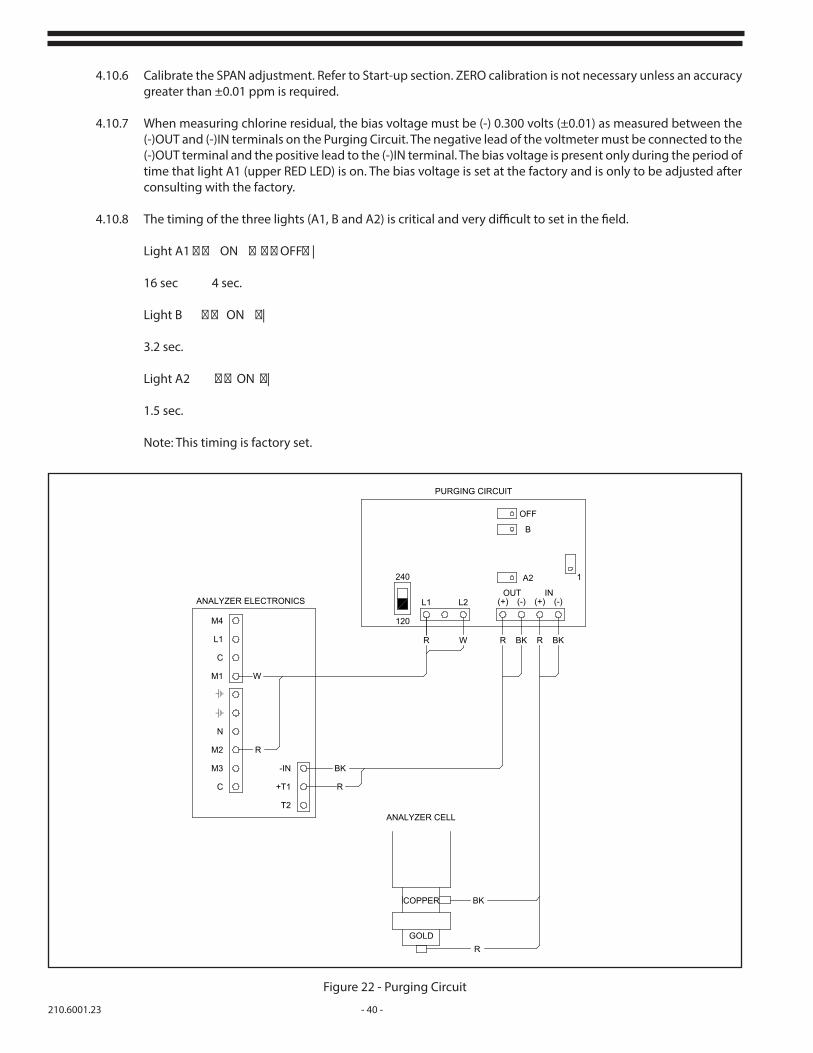
4.10.6 Calibrate the SPAN adjustment. Refer to Start-up section. ZERO calibration is not necessary unless an accuracy greater than ±0.01 ppm is required.
4.10.7 When measuring chlorine residual, the bias voltage must be (-) 0.300 volts (±0.01) as measured between the (-)OUT and (-)IN terminals on the Purging Circuit. The negative lead of the voltmeter must be connected to the (-)OUT terminal and the positive lead to the (-)IN terminal. The bias voltage is present only during the period of time that light A1 (upper RED LED) is on. The bias voltage is set at the factory and is only to be adjusted after consulting with the factory.
4.10.8 The timing of the three lights (A1, B and A2) is critical and very difficult to set in the field.
Light A1 ON OFF |
16 sec 4 sec.
Light B ON |
3.2 sec.
Light A2 ON |
1.5 sec.
Note: This timing is factory set.
Figure 22 - Purging Circuit
L1
C
M1
N
M2
M3
C
T2
+T1
-IN
W
R
ANALYZER ELECTRONICS
BK
R
COPPER
GOLD
BK
R
ANALYZER CELL
240
120
PURGING CIRCUIT
OFF
B
A2 1
L1 L2 (+) (-) (+) (-)OUT IN
R W R BK R BK
M4

- 41 - 210.6001.23
4.11 Peristaltic Tube Replacement
The peristaltic pump tubing should be changed every three (3) months. An initial supply of tubing has been included with the reagent feeder providing enough tubing for one year. Systems for Free Chlorine will have one peristaltic pump tube and one reagent pickup tube. Systems for Total Chlorine will have two peristaltic pump tubes and two reagent pickup tubes. Consult Parts List 210.7036 for more detail.
Prior to removing the pump tubing, carefully remove the pickup tubing from the reagent bottle(s) and place into a container of tap water. Allow the pump to run for a period of 15 minutes. Do not replace the pump tubing without first purging with water.
Pump tubing replacement is easy and can be performed in just a few minutes. First disconnect power from the reagent feeder. Once the power is removed, gently press on the sides of the clamp plate and pull backwards.
Gently pull the two retaining blocks from both sides of the pump and remove the tubing assembly from the pump.
The replacement tubes are cut to length and include with barb fittings. Remove the old tubing assembly from the retaining blocks and install the new tubing assembly. Refer to Figure 23.
Reinstall the tubing assembly with retaining blocks and the clamp plate, and reinsert the pickup tubing in the reagent bottle(s) before reinstalling power.
Figure 23 - Peristaltic Tube Replacement
CLAMPPLATE
BLOCKRETAINING
BLOCKRETAINING
HEADPUMP
PART NUMBER: 21132TUBING ASSEMBLY
REAGENT CONTAINERTO TO
MEASURING CELL

210.6001.23 - 42 -
5 ACCESSORIES AND RECOMMENDED SPARE PARTS
See Figure 6 for additional plumbing accessories
Figure 24 - Recorder
Figure 25 - Analyzer With Flushing Y-Strainer
Model Description
Series 1007 Circular Chart Recorder1 pen/2 pen, 120/240 Vac

- 43 - 210.6001.23
6 TROUBLESHOOTING CHART
NOTES: 1. Verify sample flow at the analyzer intake between the overflow weir and the filter screen (150 ml/minute [1 pint/min.]) at 5 psig. Verify constant sample flow through the analyzer by observing flow at the drains SAMPLE MUST ALWAYS FLOW TO THE ANALYZER.2. Verify analyzer motor is connected to the proper power supply and operating.3. Verify reagent feed to the analyzer. Let the analyzer run for 24 hours and measure reagent usage (normal 3/4" to 1 1/8" [20 to 30 mm] change in level).
Trouble Probable Cause Corrective Action
1.Excessive high or low output signal a.Air bound sample or reagent line.
b.Dirty or worn electrodec.Damaged thermistor.d.Faulty printed circuit board.
a.Check drain tubing for sample flow. For inadequate flow from left drain, tap base of flow tubing to release trapped air bubbles.b.See Service section III. Section 4.5c.Test and replace thermistor. Section 4.5d.Replace printed circuit board. Section 4.6
2.Output reacts slowly to residual change. a.Coating on measuring cell.b.Excessive suspended solids.c.Non-representative sample.
a.Clean electrodesb.Filter sample.c.Relocate sample point.
3.Motor operation noisy, erratic, no motion.
a.Faulty capacitor.b.Motor wired incorrectly.
c.Misaligned strider has PVC spheres jammed.
d.Faulty motor.
a.Replace capacitor. See Section 4.7b.Rewire per label diagram. See Figure 14.c.Adjust striker assembly. See Service Section IV. Check plug is tight in top body.d.Replace motor. See Section 4.7
4.Inadequate span adjustment a.Coating on measuring cellb.Solids in measuring cell.
c.Improper range selection.
a.Clean electrode. See Section 4.3, Calibration.b.Filter sample.c.Set range per Table I in Start-up section 3.
5.Inability to zero. a.Residual present sample a.See Section 4.7
6.Improper reagent feed. a.Faulty star wheel.b.Peristaltic Pump tube needs replacement.
b. See Section 4.11
7.Excessive reagent feed. a.Striker motor rotation reversed.
b.At shutdown, star wheel aligned for constant reagent feed.c.Worn or cracked star wheel.
a.Motor must turn counterclockwise (top view). Inspect motor leads for proper connection. See Figure 14.b.Jog motor to reposition star wheel.
c.Replace star wheel.
8.Insufficient reagent feed. a.Star wheel plugged.b.Blockage in line to star wheel.c.Peristaltic Pump tube needs replacement.
a.Clean. See Section 4.2.b.Check per Section 4.2.c. See Section 4.11
9.Display blank. a.Power Off.
b.Bad connector or incorrect wiring to display.
c.Faulty display.
a.Turn power switch ON or connect power.b.Check for proper plug connection or repair or replace cable assembly. See Figure 14. c.Replace display.
10.Display range is always off by a factor of 10.
a.Decimal point jumper in the wrong position.
a.Change position of the jumper plug. Refer to Table I in the Section 3.

210.6001.23 - 44 -
6.1 Interferences of Free Chlorine Analyzer Measurements
Interfering Compound Formula +/- Maximum Concentration Comments
Manganese MnO2 2 ppm Manganese dioxide
Sulfides S-2 - unknown Reducing complexes
High Conductivity ions +/- +/- 1000 µS
Salt Water (sea) NaCl 500 ppm High and varying
Zinc Orthophosphate Zn3 (PO4)2 - unknown Corrosion inhibitor
Silicates SiO2 - unknown Sodium silicate, corrosion inhibitor
Particulates solids - very high Suspended solids
Chromate (CrO4)-2 3 ppm Potassium chromate, corrosion inhibitor
Copper Cu 2 ppm Copper complexes
Sulfite (SO3)-2 - present Reducing agent
Metals various +/- 3 ppm
Surfactants various unknown unknown Surface acting agent
Dissolved Oxygen O2 5 ppm 10 ppm O2=about 1 ppm as Cl2
Monochloramines* NH2Cl unknown Combined chlorine
Dichloramines* NHCl2 unknown Combined chlorine
Nitrogen Trichloride* NHCl3 unknown Combined chlorine
Organic Chloramines* various unknown Combined chlorine
Chlorine Dioxide ClO2 present Oxidants
Potassium Permanganate KMnO4 present Oxidants
Bromine, Iodine and other Halogens
Br2, I2 present Oxidants
Ammonia NH3 - 150 ppm Apart from reactions with Cl2
*Chloramines are suspected interferences only in very high levels and when attempting to read low levels of free chlorine.** +/- means that the result of interferences will increase the reading (+) or decrease the reading (-).

- 45 - 210.6001.23
THIS PAGE INTENTIONALLY LEFT BLANK
210.6001.23 - 46 -
Represented by:Design improvements may be made without notice.
De Nora Water Technologies3000 Advance Lane Colmar, PA 18915 ph +1 215 997 4000 • fax +1 215 997 4062 web: www.denora.commail: [email protected]
®Registered Trademark. © 2015. All Rights Reserved.
FEB 2016