Embed Size (px)
Citation preview
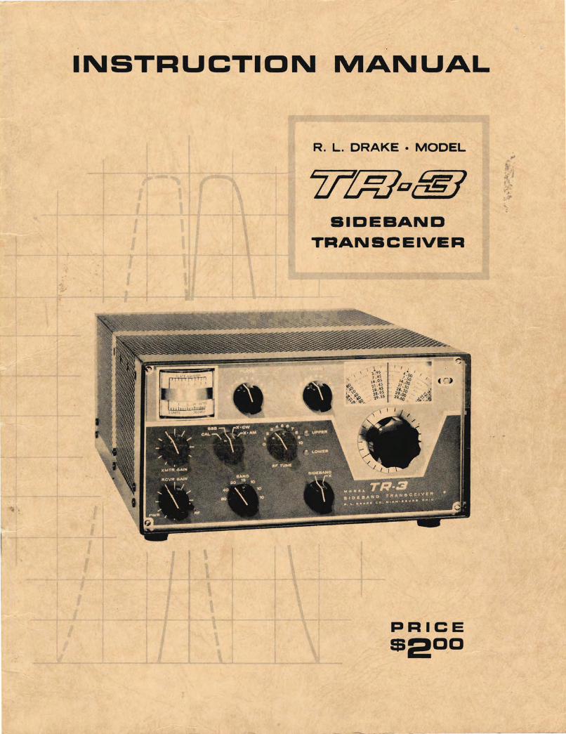
INSTRUCTION MANUAL
R. L. DRAKE • MODEL
SIDEBAND TRANSCEIVER
PRICE
$200
Drake TR RV AC DC 3 Instruction Service Manual Schematic.pdf
Scanned by
WAØTOP
15 Oct 2013
Because I couldn’t find a readable copy.

TABLE OF CONTENTS
General Specifications Transmitter Specifications Receiver Specifications Power Supply Requirements Tube Complement
I Genera 1 De scription
II Installation Instructions
A. Unpacking B· Antenna Requirements C. Spea ker Requirements D. Microphone Requirements E. Location F. Fixed Installation G. Mobile Installation
3 4 4 5 5
6
7
7 7 7 7 8 8 8
III Control Functions 13
A. Front Panel Controls 13 B. Side Controls and Jacks 14 C. Other (Carrier Balance and Dial Light Switch) 15
IV Tuning Procedure 16
A. Bias Adjustment 16 B. Adjusting Dial Calibration 16 C. Tune-up on the Desired Band 16 D. Adjustment of Carrier Balance Contrd 17
V Operation 18
A. Voice Controlled Operation on SSB 18 B. Push-to-Talk Operation on SSB 18 C. CW Opera hon 19 D. AM Operation 19 E. General Precautions for Operation Near Band Edge 20 F. Operation With Linear Amplifiers 20
VI Theory of Operation 21
A. Receiver Circuitry 21 B. Transmitter Ci rcuitry 22
-1-
VII S.'2rv~.=-;; Data
Removing Top Cover Removing Bottom Cover Tube Replacement Troubleshooting
VIII Aligc:',~nt In s t ructions
I . ; . !Z .
" r - \ - .
Cry stal Calibra tor Alignment Adj u stment 0 f 9.0 Mc Oscillator CrY.3tal Oscillator Alignment v r o Adjustment vro Output Coupler Adjustment Adj u stment of Injection Couplers Receiving I. r. Alignment Adj u stment of Bal. Modulator Output Tra ns former Filter Ma tching Tra ns former Carr ier Balance Adjustments Adj u stment of Mixer and Rr Coils Final Amplifier Neutralizing Tra n smitter I. r. Neutralizing
IX AC-3 ? :::wer Su pply Instructions
X DC- 3 ? Jwe r SJpply Instructions
XI RV-3 : .2mote vro Instructions
CHARTS AND ILLUSTRATIONS
25
25 25 25 25
30
30 30 31 31 31 31 32 32 32 32 33 33 33
34
35
3.7
Fig. #1 C:nnecting the TR-3 to the AC-3 and MS-3 10 Fig. #2 C : :mect ing the TR-3 to a linear amplifier 10 Fig. #3 C :: i ng the TR-3 with an e xternal rec '? iv·?r 11 Fig. #4 L ec trica l connection for mobile installation of TR-3 11 Fig. #5 : .~ 2::;hanical details for mobile installation 12 Fig. #6 E. ~:ck Diagram 24 Fig. #7 S2~2ctivity Curves 24 Fi g. #8 \ ": ~ t age C hart 26 Fig. #9 R2s i stance Chart 27 rig.#lO -::-:OJ view photo 28 Fig.#ll :=:::to m view photo 29 Fig.#12 ':-,:::--3 sc hematic diagram 34 Fig.#13 0;:::: -3 s '::; h e matic diagram 36 Fig.#14 ::",'-3 schematic diagram 40 Fig.#lS -=- ?-J s c hematic dia gram 41
-2-
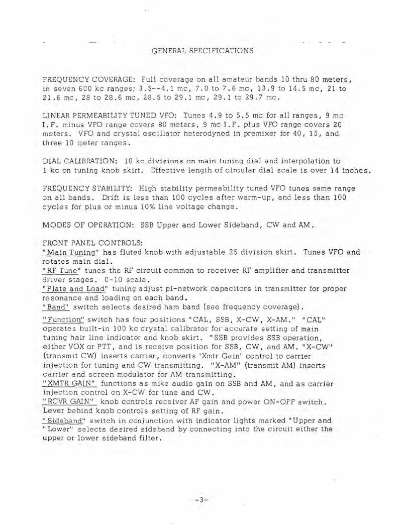
GENERAL SPECIFICATIONS
FREQUENCY COVERAGE: Full coverage on all amateur bands 10 thru 80 meters I
in seven 600 kc ranges; 3.5--4.1 mc , 7.0 to 7.6 mc, 13.9 to 14.5 mc, 21 to 21 .6 mc, 28 to 28.6 mc, 28. 5 to 29. 1 mc, 29. 1 to 29. 7 mc.
LINEAR PERMEABILITY TUNED VFO: Tunes 4.9 to 5.5 mc for all ranges, 9 mc I. F. minus VFO range covers 80 meters I 9 mc I. F. plus VFO range covers 20 meters. VFO and crystal oscillator heterodyned in pre mixer for 40 I 15, and three 10 meter ranges.
DIAL CALIBAATION: 10 kc divisions on main tuning dial and interpolation to lkc on tuning knob skirt. Effective length of circular dial scale is over 14 inches.
FREQUENCY STABILITY: High stability permeability tuned VFO tunes same range on all bands. Drift is less than 100 cycles after warm-up, and less than 100 cycles for plus or minus 10% line voltage change.
MODES OF OPERATION: SSB Upper and Lower Sideband, CVV and AM.
FRONT PANEL CONTROLS: "Main Tuning" has fluted knob with adjustable 2S division skirt. Tunes VFO and rotates main dial. "RF Tune" tunes the RF circuit common to receiver RF amplifier and transmitter driver stages. 0-10 scale. "Plate and Load" tuning adjust pi-network capacitors in transmitter for proper resonance and loading on each band. "Band" switch selects desired ham band (see frequency coverage) .
"Function" switch ha s four positions" CAL, SSB I X-CW, X-AM. ,i "CAL" operates built-in 100 kc crystal calibrator for accurate setting of main tuning hair line indicator and knob skirt. "SSB provide s SSB operation I either VOX or PTT I and is receive position for SSB, CW I and AM. "X-CW" (transmit CW) inserts carrier I converts 'Xmtr Gain' control to carrier injection for tuning and CW transmitting. "X-AM" (transmit AM) inserts carrier and screen modulator for AM transmitting. "XMTR GAIN" functions as mike audio gain on SSB and AM I and as carrier injection control on X-CW for tune and CW. ," RCVR GAIN" knob controls receiver AF gain and power ON-OFF switch. Lever behind knob controls setting of RF gain. "Sideband" switch in conj unction with indicator lights marked" Upper and "Lower" selects desired sideband by connecting into the circuit either the upper or lower sideband filter.
-3-
RIGHT SIDE SCREWDRIVER ADJUST CONTROLS: Vox Gain, Anti-Vox Gain, S- Me:er
Zero.
INSIDE SCREWDRIVER ADJUST CONTROLS: Carrier Balance.
RIGHT SIDE JACKS: Headphone (disconnects speaker circuit), M ic roph::me (3-circuit for PTT). Key (normally close d) .
REAR CONTROLS: "LIGHTS " s'Nitch brightens and dims pilot lights.
METERS: Separate receiver S-meter/transmitting AGC indicator I and tran'smitter plate amMeter.
MISC: 20 tubes including voltage regulator; 6 diodes; 100 kc crystal calibrato r built-ina Dimensions: 5-1/2" high, 10-3/4" wide, cabinet depth 14-1/2", overall depth including knobs 14-3/4". Weight 15 lbs 14 oz.
TRANSMITTER SPECIFICATIONS:
SINGLE SIDEBAND: 300 watts P. E. P. input power. VOX or PTT. Two special 9 mc crystal filters provide sideband selection, upper or lower on any band, without the necessity of shifting oscillators. The 9 mc filters are asymmetrical, that is, steeper on the carrier side (see filter selectivity charts) making pos sible unwanted sideband suppression of more than 40 db above 750 cycles and carrier suppression of 50 db. Overall audio frequency response 400 to 2500 cycles at 6 db down. Distortion products 35 db down at maximum output.
CW; Power input 260 watts. Carrier is shihed approx. 1000 cycles into one sideband and mixer is keyed. Grid block keying is free from chirps and clicks. Manual transmit/receive switching.
AM: Controlled carrier AM screen modulator is built-in. 260 watts P.E.P. in!=l"-lt. Low carrier power increases 6 times to 50 watts output at maximum mod ulation. This system is compatible with SSB linears. Manual transmit/receive s witchin;;.
OUTPUT IMPEDANCE: Nominal 50 ohms, adjustable with pi-network.
MICROPHONE INPUT; High impedance.
RECEIVER SPECIFICATIONS
SENSITIVITY: Less than 1/2 microvolt for 10 db SiN.
1. F. SELECTIVITY: 2.1 kc at 6 db, 7.5 kc at 6 0 db.
AGe; FULL AGC on received modes -- audio output varies less than 3 db for 60 db change in signal level. Any amount of AGC from zero to full can be had by adjustment of RF gain control. Time proven Drake AGe system provide s fas ~
attack and slow release with noise pulse sup;xession, n::) pumping ::)[ p::)pping evident.
-4-

AM: Product detector reception of AM (known as exalted carrier method) requires zero beating signal. Advantages over diode detectors include no selective fading, choice of either sideband I and better a1,.ldio frequency resp::mse at 2. 1 KC selectivity I re sulting in more QRM free QSO' s.
ANTENNA INPUT: Nominal 50 ohms.
AUDIO RESPONSE: 400-2500 cycles at 6 db.
AUDIO OUTPUT POWER: 2 watts.
AUDIO OUTPUT IMPEDANCE: 4 ohms.
POWER SUPPLY REQUIREMENTS
Due to the 300 watt P.E.P. input rating, the TR-3 will require a power supply capable of low voltage at high current with very good dynamiC regulation. The voltage and current requirements are a s follows: 1. 650 volts at 300 rna average and 500 rna maximum with 10% regulation
from 100 rna to 500 rna and maximum ripple of less than 1%. 2. 250 volts at 174 rna with 10% regulation from 150 rna to 180 rna. This
includes the effect of the 650 volt supply change if both voltages are obtained from the same transformer. Maximum ripple must be less than 1/4%.
3. -45 to -65 VDC adjustable filtered bias into 33 K ohm load. 4. 12.6 Volt AC or DC at 5.5 amps.
TUBE Complement
1'lM7A 6EV7 6GX6 12BA6 12BA6 12BA6 12AX7A 6AQ5A 6HS6 6EA8 6EA8
6AU6A 13DE7 12BA6 12BA6 12BY7A (3) l2JB6 OA2
Transmitter Mike A.mp.
Vox A.rnp./Relay 9 MC Xtal Osc.
I. F. Amp.
AGC Anti-Vox
Mixer Cathode Fol.
Pre-Mixer/Xtal Osc. VFO
AM Screen Mod.
Driver Power Amps Voltage Reg.
-5-
FUNCTION Receiver
BFO/Prod. Det.
1.F. ~mp. 1. F. Amp.
AGC Audio Output
Mixer /Ca th. Fol. Pre - Mixer/Xtal Osc.
VFO
R.F. Amp. Crystal CaUb.
Voltage Reg.
•
I GENERAL DESCRIPTION
The R. L. O:-=<e model TR-3 is a single sideband transceiver designed for the transmission a nd reception of upper and lower sideband signals on the 80 through 10 me ter amateur bands. AM and CW capabilities are included.
Its co:npact s ~ ze makes it ideal for both fixed station use in conjunction with our mo ce,l AC-3 120 volt AC Power SJ.pply, or for mobile installations using our mo de l DC-3 12 volt DC Power Supply.
The 300 wa h ?EP input on SSB enables the TR-3 to give an excellent account of itse lf " bc:-e foot" and it will drive the highest powered ham linear amplifiers.
Upper and lo o .... er side band selection is accomplished by switching between two Drake desig:12d and manufactured 9 Mc crystal lattice filters with 2.1 kc pas sbands. Amon; the other features included on the TR-3 are VOX and PTT I shifted carrier CW I s2para~e RF and AF gain controls I linear permeability tuned VFO with vernie r scale I transmitting and receiving AGC I and separate receiver S-meter and transmi':i:er plate ammeter.
The additio n cf the accessory RV.:.3 remote VFO speaker combination enables the c~erator to receive I t ransmit,or transceive throughout the band being : .. sed without disturbing the setting of the TR-3 tuning dial. This is usebl for working DX stations operating outside the United States Phone Bands I or for working near your own frequency in search of a clear spot under c:-cwded band conditions .
-6-
II INSTALL-t\TION INSTRUCTIONS
A. UNPACKING:
Carefully remove your TR-3 from its packing carton and examine it closely for signs of shipping damage. Should any be apparent, notify the delivering carrier immediately, stating the full extent of the damageo
Fill out and mail the enclosed registration card so that your warranty will be effective.
S,:l.Ve the packing material, it was expensive and you may need it later for
reshipment or storage.
Inspect the packing material closely before putting it away to be sure you have not overlooked the Switchcraft type S-230 and 229 plugs shipped with the TR-3.
B. ANTENNA REQUIREMENTS:
The TR-3.is designed for use with antennas re sonant on the operating frequency and having approximate impedances of from 30 to 100 ohms. Although there are many types of antennas which will meet this requirement, the simpliest is a one half 0/2) wa ve dipole I center fed with 52 ohm coax. For a detailed discussion on antennas I we suggest you refer to the ARRL Antenna Book or The Radio Amateur's Handbook.
Antenna connection to the TR-3 is provided at the SO-239 coax connector located on the rear of the shielded compartment housing the final amplifier components.
Caution: NEVER ATTEMPT TO OPERATE THE TR-3 WITHOUT FIRST CONNECTING .-IT TO AN ANTENNA OR 52 OHM DUMMY LOAD OF SUFFICIENT POWER HANDLING CAPACITY OR SERIOUS DAMAGE CAN RESULT.
C. SPEAKER REQUIREMENTS:
A goed qua lity 4 ohm speaker should be connected to terminals 7 and 12 of the female power plug mated to the TR-3 or plugged into the phone jack on the side. If our model AC-3 or DC-3 power supplies are used, a 6-inch lead terminating in a female phono plug is attached to these terminals of the power plug on the end of the power cable. Our model MS-3 speaker I available from your dealer, p:-ovides a very good match and is compatible in appearance with the TR-3. It will also house the model AC -3 120 VAC power supply.
D. MICROPHONE REQUI REMENTS:
A microphone with a wide and flat frequency response will enable you to obtain peak performance from your TR-3. For good VOX or voice control operation it is desirable for the mike to have a cardiod pattern to reduce
-7-

pid:up from the back and side s of the mike. This ena ble s you to operate with higher receiver audio gain, giving better VOX operation and reducing echoes I reverbera tion, and noise pickup in the fixed or mobile installation. Microphones with limited low or high frequency response and with peaks in the voice range should be avoided.
A three conductor microphone plug (Switchcraft type S230) is provided wi th the TR- 3. The microphone must be connected ass hown here for proper VOX and push to talk operation. Many microphones that are furnished with a switch were not wired this way.
D. LOCATION:
1--, ~t_n=~~~ : ~i ..
S-230 CONNECTOR L- __ ~ (SWITCHCRAFr)
MICROPHONE
In general, the location of the TR-3 is not critical, either in fixed or mobile installations. However, care should be taken to insure that space is allowed around the unit to allow adequate air circulation. Extremely hot locations, such a s near radiators or hea Ling units, should be avoided. Do not cover the top of the TR-3 with books, paper, or pieces of equipment or overheating may result.
E. FIXED INSTALLll.TION:
For fixed installation, our model AC-3 120 VAC 50/60- cycle power supply will be required and the model MS-3 matching speaker is highly desirable. Connect thes9 units as shown in figure 1 . Note that the AC-3 power supply will fit inside the MS-3 to form one compact unit. If your linear amplifier has ALC, it can be applied to the TR-3 at pin 3 of the p::Jwer connector. The uS9::Jf shielded wire is recommended. Figure 2 shows how the TR-3 can be conne·cted for operation with linear amplifiers.
F. MOBILE INSTALLATION:
The TR-3 may be installed in any vehicle having a 12 VDC electrical system. Our model DC-3 power supply will be required for this installation. All DC-3 supplies are factory wired for negative ground systems.
IF YOUR-CAR HAS A POSITIVE GROUND SYSTEM, DO NOT ATTEMPT TO CONNE CT] THE DC-3 UNTIL THE PROPER WIRING CHANGES HAVE BEEN MADE! SEE DC-3 INSTRUCTIONS. __ . ___ _
1. Mount the TR-3 in a c ::mvenient location under the da sh using the MMK-3 mobile mounting kit. See Figure 5 hr more detailed instructi::ms on various suggested mo unting methods.
-8-

Bo'? sure to :=1110\'1 adequate clearance for air circulation and at the right side for access to the s ':::rew driver adjustments and the mike jack.
2. The recommended mounting position for the DC-3 Power Supply is on the passenge r side of the firewall. We do not recommend that it be placed in the trunk due to t he excessive primary lead length or in the engine compartment unless it is protected from water and engine heat.
Make sure that the on-off switch on the TR-3 is in the off position (Audio gain fully c o unter clockwise until click is heard) and connect the female power conne·:::ter on the end of the power cable, to the TR-3. Coil up excess cable and tape in an out-of-the-way location. You may need the extra length when you trade cars. Run the black wire from the power supply to a convenient ground and run the red wire through the fire wall to the battery terminal of the starter relay. Shorten the heavy red and black wires as much as possible.
3. Install a mobile antenna in thf. manner recommended by the antenna manufacturer and connect the coax lead from it to the SO-239 connector :;If the TR- 3. It rna y be nece ssary tJ install a ma tching coil at the antenna feed point in order t o match it to the feed line impedance. The. use of an SWR bridge is recommended. For details on this refer to the mobile antenna section of the ARRL Radio Amateur's Handbook.
4. If your car has a transistor radiO, we suggest you install a separate speaker for use with the TR-3. However, if the radiO in your car has a vacuum tube audio amplifier, and if one side of its speaker is grounded, run a wire from the ungrounded terminal to the center conductor of a male phone plug. Insert this plug in the female jack molded into the end of the 6-inch wire protruding • from the connecter on the end of the DC-3 power cable. It should be unnecessary to disconnect the auto radiO output transformer when the TR-3 is used unless it has insufficient volume. If this proves to be the case, a SPDT switch can be installed so that the speaker lead goes to the pole, the car radio output goes to one contact and the TR-3 output goes to the remaining contact.
5. If ignition noise is a problem, we recommend the installation of resistor type spark plugs, a 10,000 ohm suppressor resistor inserted in the center tower of the distributor, and 5000 ohm suppressor resistors at each spark plug to\,\' er on the distributor. Install a coaxial capacitor at the ignition coil primary as close to the coil terminal as possible.
To suppre ss ge ne rator nOise, install another coaxial capacitor (.1 to .25 MFD) in the generator output lead as close to the output terminal as possible.
To suppre ss voltage regulator noise, install bracket mounted 80axial capacitors at the generator output and battery leads to the 'loltage regulator. Mount the capacitors as ~ lose to the regulator as possible. A. 002 MFD mica capacitor with a 4 ohm carbon resistor in series should be connected from the generator field terminal of the regulator to ground. Do not use a capacitor across the
-9-
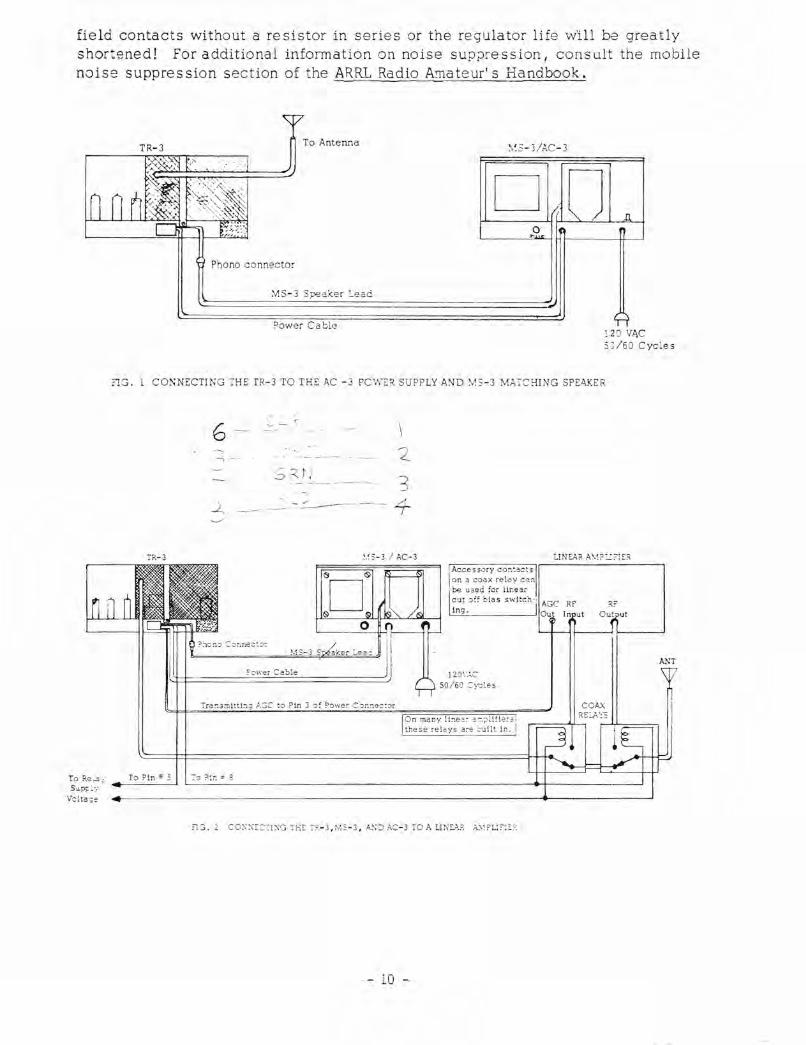
field contacts without a resistor in series or the regulator life wIll be greatly shortened! For additional information on noise sup;Jression, consult the mobile noise suppression section of the ARRL Radio A!Tlateur' s Handbook.
TR-3 To Antenna
\~S-3/AC -3
D o "
~l~p=h=o=n=o=c=o=n=n=~=c=:O=:=3=S=pe==C=k=e=r=L=e=ca='==================~ Power Cable
-J
12 0 V.l>,C
5';/60 Cycles
2G. 1 CONNECTING THE TR-3 TO THE AC - 3 PCW ER SUPP LY AND VS-3 MATCHING SPEAKER
TR-3 r----..,,=
To Re..2":· S";Jp;:~y
Volta;~
To Pin" 5
:-ra~.3mittL ,~ ::;c to Pin 3 :>: Power C
4
'.'S-3 / AC- 3 UNEAR A\1? :":?I£:::\
ANT
50/60 Cyc les
- 10 -

To Re_ta y S upply
Vo ltage
:
!'R-3 AC-3/MS-3
IE: Leave L1.!s switch
on Ucter-:;al ReV when nc ~ in use.
120 VAC SO /60 Cycles
2-8
C oax Rela'y
,IG, 3 CS1:\G THE TR-3 \v1TH AN EXTERNAL RECEIVER
TR-3 DC-3
Red (Connect to ungrounded terminal of ba ttery or to
Cl=========~~~=g-i:::------ starter rela y.) Slacio
Phono C onne:;tor
B-3
.-----.... [ Ca~ , R'3 dio
To car radio output transfo!!ner.
S2 ohm coax
Car Radio Speaker
(Gro~_-:c to car body.)
Mo::22 Ar::-e::::-.a
Loa cL-.; Coil
Ma:.=~.Jng Coil
FIG. 4 ELECTRICAL CONNECTIONS FOR MOBILE INSTALIATION OF THS TR-3
-11-

Fig . 3 ).1ECHANICAL DETAILS OF MOBILE INSTALLATION 'JSING MMK-3 MOBILE MOUNTING KIT
Four threaded h o le s are :J:-: "-c:?: in each side of the :'<.-3 tc:: :;: .,,~:: aeceQt wing bolts, c:ld fo~~ ::>==~,?: hole s are provided at the re =c~ ?:i:;" :: the l:;ottom c o ver fc ~ :counti:-.:; :: ~~ tongue. (four 6- 32 3GewS .0 ~,~ C:~::
provided). The tonqcie ha L: 7C :;,,~. ::,.0
mounted t o t he floo~ :Jr trar . .o:-:-,,:,::~:: c. hump by drilling tw :) 3/16 -: .-,::. ::':~7= and fastening it dO·"'7) Nith ~-,~ :-A': =~~ sheet metal screws ;;covide::. ~, :-:e ::.at two fibre washers ",e provi ::?:: ,,,-'-...:=. mus t be po.itioned :::Etwee:-~ ::-~ = :-~. - ;
case and the mount:c.:] brac ·",,: . --~:~ washers are not sh o·,'o- i1 .
to the da sh eit her wi : ~"1 the :-"": = ~ ~ ,:-.eet metal screws or the 1/4-inc ·:: :l:~: :: o::c nuts (both sets pro vided). ,~, :i:.~:::::-c~
holes may be drilled in brae t~= : : : ::2-:.:h existing holes in the :iash .
Fig. ~B
Fig.
Fig. SC
Fig. 5£
-12-

III CONTROL FUNCTIONS
A. FRONT PANEL CONTROLS:
1. Main tuning - The main tuning knob of the TR-3 determines the frequency on which you transmit and receive. Each division around the calibrated skirt on this knob is equal to approximately 1 kc and each division on the main tuning dial is equal to 10 kc. The small red knob just to the right of the dial scale is for adjusting the position of the indicator line for calibration. The knob skirt is also adjustable by pushing it in slightly and rotating it in the de sired direction, while holding the main tuning knob stationary.
2. SIDEBAND - The SIDEBAND control selects either of two 2. 1 kc crystal filters for transmis sion and reception of upper and lower sidebands. Directly above this control are two indicator lights which show the sideband in use for a particular band. You will notice that one position of this switch is marked with an "X". This position must be used when transmitting AM or CW or when tuning up.
3. BAND - The BAND control is a seven-position switch used to select the ama teur band de sired. You will notice that it has three 10-meter positions. Proceeding in a clockwise direction, the first covers 28.0-28.6 Mc, the second covers 28.5-29.1 Mc and the third covers 29.1-29.7 Mc.
4. RCVR GAIN - The RCVR GAIN control consists of two controls with concentric shafts. The lever controls the maximum RF gain of the recei ver by varying the amount or negative bias applied to the grids of the AGe controlled tube s.
The knob adjusts the audio gain by regulating the input to the grid of the audio power amplifier tube. The transceiver power switch is operated at the extreme counter clockwise end of rotation of this knob.
5. XMTR GAIN - This control regulate s the microphone gain on AM and SSB. When the unit is operated on CW it is used to adjust tIle RF drive to the proper level.
This control is connected so that it regulates the VOX sensitivity as well as the audio drive to the balanced modulator. Since all changes in level due to the type mic, how close or loud you talk, etc., effect equally the VOX and audio drive requirements, this eliminates the necessity of changing the VOX adjust control, located on the side of the TR-3 chassis, once it is set properly.
-13-

6. FUNCTI O N CO NTROL - The FUNCTION CONTROL is a four-p':Jsition switch which determines the mode of op<::ration of the TR-3.
In the SSa positi-:)n the receiver pJe"tion functions until the transmitter is energized eithe:- by ta l k iw; into t he microphone .:X pressing the push-to talk switch. T:-ie t ransmitter then emits an upper or lower sideband signal d2pending on t !! 2 s9tti ng o~ the SI DEBAND switch.
In the CAL position, the 100 kc crystal calibrator,is switched on for calibration purp':JS 9 S. Tbe , e ::: e i v e and trans mit functions operate the same as in the SSB position.
In the X-CW pos ition the transmitte r is switched on, the receiver is switched off, and the carr ie r is shifted app:-oximately 1 kc from the received frequency. This position is to be used for tune-up and for C\V.:Jperation, and is for transmit only. When yo u wish to rec e ive you must switch back to the SSB position. Note that the SIDEBA ND switch must be placed on the" X" position when operating X-CW or X-AM. Other-vise n.:J RF output will be obtained.
On the X-AM p,:)sition, a controlled carrier screen modulator is incorp::Jrated for AM transmission. As is the case::Jn X-Cl"!..., the SIDEBAND s\Nitch must be on the" X" position for transmit and th e function switch must be returned to SSB for rece i ve .
7. RF TUNE - rhe RF TUNE control peaks the driver and RF amplifier grid and plate coils.
8. PLATE - The PLATE control tunes the power amplifier Pi network circuit to re sonance by vaqling the input cap3ci ty.
9. LOAD - The LOAD control matches the impedance of the transc:eiver power amplifier t o the impedance of the l03d by varyin;; the output capacity of the Pi network circuit.
10. S-METER - The S-METER indicates relative signal strength of the received signal. It is calibrated in S-units from S-l to S-9 and in DB over S-9. Each S-unit equals approxima tely 5 DB and S-9 equals about 30 microvolts. On transmit it indicates the pOint at which the transmitting AGC starts, to help in setting the proper level of the XMTR GAIN CONTROL.
11. PLATE AMPERES - The PLATE AMPERES meter indicate s plate current in the final amplifier tub2s .
B. SIDE CONTROLS AND JACKS (front to rear) .
1. PHONES - The headphone jack automatically disconnects the sp2aker when headphones are p lugged in. The audi::J output impedance at the jack is 4 ohms.
-14-
:u lit.· nY. ------ ~.---

(An excellent set of headphones for this impedance is Trimm model 24-08). (A speaker may be plugged in here instead of connecting it to the power connecter if desired.) A Switchcraft type 229 plug (red) is supplied with the TR-3 which can be used either here or at the KEY jack.
2. MIC - This is a .210-inch diameter phone jack of the three conductor variety (Switchcraft S-230) to accommodate microphones with push-to-talkswitches.
3. VOX - The VOX control is for adjusting the gain ::Jf the VOX amplifier.
4. ANTI VOX - The ANTI VOX control adjusts the sensitivity of the anti VOX amplifier.
5. ZERO - The S-METER ZERO control is for adjusting the no signal reading of the S- METER t::J S-l.
6. KEY - The KEY jack is of the normally closed variety. Note that plugging a key into this jack will disable the transmitter on a'll modes of operation unless the key is closed.
C. OTHER:
I. CARRIER BAL~NCE - The CARRIER BALANCE control is a potentiometer located on top of the chassis, along the rear edge. It is for balancing the balanced modulator. Note that this control has a planetary drive and requires 10-1/4 turns for complete travel.
2. lJGHTS - The LIGHTS control is a two pOSition slide switch located on the rear of the TR-3 chassis. It is used to control the brilliance of the dial lights. The letters D and B indicate dim and bright respectively,'
-15-
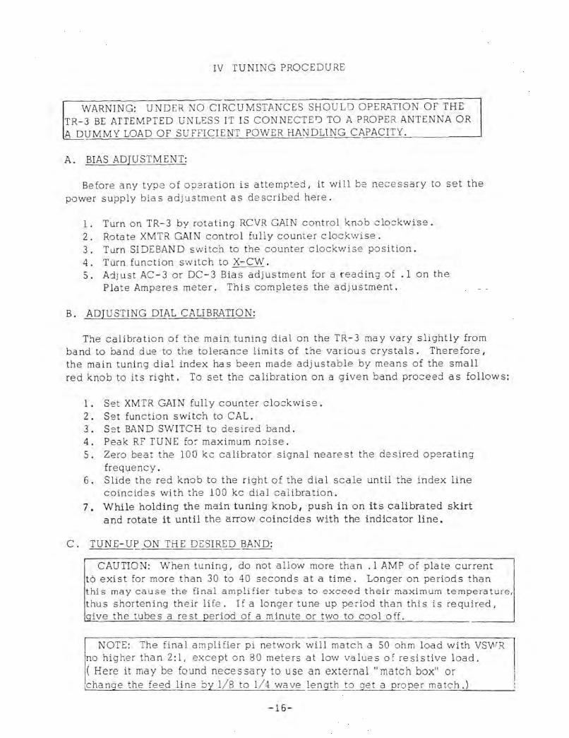
IV TUNING PROCEDURE
WARNING: UNDER NO CIRCUMSTANCES SHOULD OPERATION OF THE TR-3 BE ATTEMPTED UNLESS IT IS CONNECTED TO A PROPER ANTENNA OR A DUMMY LOAD OF SUFFI~JENT POWER HANDL1NG CA~P~A~C::c:I~T...:.Y--!.... _____ --,
A. BIAS ADJUSTMENT:
Before any type of op2ration is attempted, it will be necessary to set the power supply bias ad jus tm e nt as described here.
1. Turn on TR-3 by rotating RCVR GAIN control knob clo:;kwise. 2. Rotate XMTR GAIN control fully counter clockwise. 3. Turn SIDEBAND switch to the counter clockwise position. 4. Turn function s w itch to X-CW. 5. Adjust AC-3 or DC-3 Bias adjustment for a reading of .1 on the
Plate Amperes meter. This completes the adjustment.
B. ADJUSTING DIAL CALIBRATION:
The calibration of the main tuning dial on the TR-3 may vary slightly from band to band due to the toler.ance limits of the various crystals. Therefore I
the main tuning dial index has been made adjustable by means of the small red knob to its right. To set the calibration on a given band proceed as follows:
1. Set XMTR GAIN fully counter clockwise. 2. Set function switch to CAL. 3. Set BAN D SWITCH to desired band. 4. Peak RF rUNE fo:- maximum noise . 5. Zero beat the 100 kc calibrator signal nearest the desired operating
frequency. 6. Slide the red knob to the right of the dial scale until the index line
coincides with the 100 kc dial calibration. 7. While holding the main tuning knob, push in on its calibrated skirt
and rotate it until the arrow coincides with the indicator line.
C. TUNE-UP ON THE DESIRED BAND:
CAUTION: When tuning, do not allow more than .1 AMP of plate current t6 exist for more than 30 to 40 seconds at a time. Longer on periods than this may cause the final amplifier tubes to exceed their maximum temperature, thus shortening their life. If a longer tune up period than this is required,
ive the tubes a rest oeriod of a minute or two to cool off.
I NOTE: The final amplifier pi network will match a 50 ohm load with VSWR Ino higher than 2:1, except on 80 meters at low values of resistive load. j( Here it may be found necessary to use an external" match box" or [change the feed line by 1/8 to 1/ 4 wave length to get a proper match .)
-16-
Preset the controls as follows:
1. BAND SWITCH to desired band. 2. Frequency knob to a frequency inside of the amateur band in use. 3. XMTR GAIN fully counter clockwise. 4. LOAD fully counter clockwise. 5. SIDEBAND in the" X' position. 6. Function switch on SSB. 7. RF TUNE - Temporarily peaked on received noise.
Rotate the function switch to the X-CW position and advance the XMTR GAIN control clockwise until the Plate Amperes meter moves up scale slightly from idling current. (If plate current is high even with XMTR GAIN fully counter clockwi se, reduce it to idling by adjusting CARRIER BALANCE control, see next section, D.) Peak the RF TUNE control for maximum plate current and quickly tune the PLATE control for a dip in plate current. When the dip is found, rotate the XMTR GAIN clockwise until plate current no longer increa ses.
Rotate the LOAD control clockwise in small inClemehts while alternately readjusting the PLATE control to maintain the dip. Continue this procedure until the plate current is .45 amps. * when dipped. Complete this procedure as quickly a s possible and return the function switch to SSB.
* Under many conditions (line voltage, tube condition, drive, etc.) the current value to which the transmitter is loaded, should be modified from the .45 amp figure stated. We recommend that an R. F. output indicator such a s a reflected power meter, SWR bridge, field strength meter I or light bulb, etc., be used and the transmitter loaded to maximum output less. 025 amps plate current. Plate current in excess of that obtained at max. R. F. output will result in excess plate dissipation and will quickly destroy the output tube.
Notice that when the function switch is in the X-CW position, the screen voltag e on the final amplifier tubes is reduced to prevent overheating. When the switch is on SSB, this voltage is increased so that a peak power input of 300 watts can be obtained.
D. ADJUSTMENT OF CARRIER BAlA.NCE CONTROL:
The CARRIER BALANC E control is factory adjusted and should require a mlnl ffiUm of re setting under most conditions. However, it should be checked before the TR-3 is operated on SSB.
After t uning up the TR-3 as described above, set the SIDEBAND switch to "Xlf, the XMTR GAIN fully counter clockwise, and the function switch to X-CW. NmN adjust the CARRIER BALANCE control (located on top of the chassis near the rear edge) for minimum plate current. (If plate current cannot be reduced to idling value, adjustment of carrier balance capacitor may be necessary. See section VIII). Return the function switch to SSB. This completes the adjustment.
-17-
. j
V OPERATION
In the followin~ discussion, it is assumed that the TR-3 has already been tuned up on the desired band as described under tuning procedures.
A. VOICE CONTROLLED OPERATION ON SSB.
Preset the controls as follows:
SIDEBAND On desired sideband as shown by indicato r lights.
FUNCTION SWITCH On SSB.
XMTR GAIN Fully counter clockwise.
RF GAIN Fully clockwi S8.
AF GAIN Fully counter clockwise (do not turn off power) .
vox GAIN Fully clockwise.
ANTI VOX Fully counter clockwise.
While talking into microphone in a normal voice, increase the XMTR-GAIN control until the S-meter starts kicking up scale 2 or 3 S-units. This indicates that transmitting AGC is starting to work and transmitter is peaking at maximum output. Continue talking and reduce the VOX GAIN until a point is reached where further reduction results in too frequent rela y drop out.
Now increase the AF gain until received signals are of the desired volume. This may cause the transceiver to cycle back and forth between transmit and receive. Adjust the ANTI VOX ADJ. until this cycling stops. You are now ready to operate.
B. PUSH-TO-TALK OPERATION O"N SSB.
If the push-to-talk switch on your microphone is properly connected as described under installation instructions, it may be depressed at any time thus over-riding the VOX sy stem.
If you dJ not desire the VOX to function at all, turn the VOX adjust control fully counter clockwise.
REMEMBER: On SSB the TR- 3 transmits on exactly the same frequency on which it recei ve s. Therefore I be sure that before you answer another station's CQ or break another QSO, you ha ve the signals tuned in so tha t the voices sound nJrmal. Otherwise you will nJt be transmitting exactly on frequency.
-18-

c. CW OPEPATION:
To work CW, plug your key into the KEY jack. If an electronic keyer is used, connect it for grid block keying.
Note that the TR-3 uses shifted carrier CW. With this system it is possible to transmit approximately on the received station's frequency without being zero beat while receiving. The receiving BFO differs from the transmitted Signal frequency by about 1 KC which allows a 1 KC tone to be heard.
To receive CW signals, place the function switch on the SSB position and the SIDEBAND switch in the" Xli position. Tune in a CW signal for an audio pitch of about 1 kc and adjust the audio gain control for pleasing volume.
To transmit, turn the function switch to the X-CW position, depre ss the key, and rotate the XMTR GAIN control clockwise until the plate current no longer incr"ease s. DO NOT ADVANCE IT BEYOND THIS POINT.
D. AM OPERATION:
As is the case on all other modes of operation the function switch must be in the SSB position to receive.
The TR- 3 uses the exalted carrier method of reception for AM which require s zero beating the signal. This method ha s the following advantage s:.
1. No selective fading. 2. Better audio frequency response when using the 2.1 KC passband. Using
diode detection it would be necessary to have the carrier in the passband thereby limiting audio frequency re sponse. With the product detector, the audio response is 400 to 2500 cycles.
3. Because you are receiving only one sideband at a time, you can easily switch to the other sideband in the TR-3 to avoid interference.
When transmitting on AM, the function switch must be on X-AM and the SIDEBAND switch must be on the" X" position. Then, while talking intG the microphone in a normal voice, rotate the XMTR GAIN control until plate current peaks between .2 and.25 amps. Care should be taken to stay within these limits since the transmitting AGC does not work on AM.
The TR- 3 uses a controlled carrier AM screen modulator which holds the unmodulated carrier input power to a few watts but allows 260 watts P. E. P. input on voi-ce peaks.
This system is compatible with SSB linear amplifiers. Due to the low duty cycle of this type of AM, a linear can be run with the same P. E. P. input a s it can on SSB.
-19-
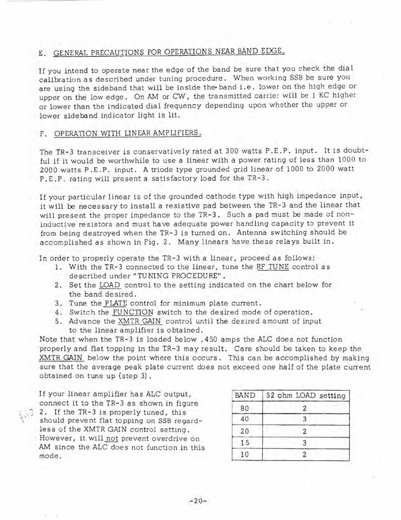
E. GENERAL PRECAUTIONS FOR OPERATIONS NEAR BAND EDGE.
If you intend to operate near the edge of the band be sure that you check the dial calibration as described under tuning procedure. When wo rk ing SSB be sure you are using the sideband that will be insIde the- band i. e. lower on the high edge or upper on the low edge. On AM or CW, the transmitted carrie :- will be 1 KC higher or lower than the indicated dial frequency depending upon \vhether the upper or lower sideband indicator light is lit.
F. OPERATION WITH LINEAR AMPLIFIERS.
The TR-3 transceiver is conservatively rated at 300 watts P.E. P. input. It is doubtful if it would be worthwhile to use a linear with a power rating of less than 1000 to 200 a watts P. E. P. input. A triode type grounded grid linear of 1000 to 2000 watt P.E.P. rating will present a satisfactory load for the TR-3.
If your particular linear is of the grounded cathode type with high impedance input, it will be necessary to install a resistive pad between the TR-3 and th€ linear that will present the proper impedance to the TR-3. Such a pad must be made of noninducti ve re sistors and must ha ve adequate power handling capacity to prevent it from being destroyed when the TR-3 is turned on. Antenna switching should be accomplished as shown in Fig. 2. Many linears have these rela ys built in.
In order to properly operate the TR-3 with a linear, proceed as follows: 1. With the TR-3 connected to the linear, tune the RF TUNE control as
described under" TUNING PROCEDURE" . 2. Set the LOAD control to the setting indicated on the chart below for
the band de sired. 3. Tune the PLATE control, for minimum plate current. 4. Switc h the FUNCTION switch to the de sired mode of operation. 5. Adva nce the XMTR GAIN control until the desired amount of input
to the linear amplifier is obtained. Note that when the TR-3 is loaded below. 450 amps the ALC does not function properly and flat topping in the TR-3 may result. Care should be taken to keep the XMTR GAIN below the point where this occurs. This can be accomplished by making sure that the average peak plate current does not exceed one half of the plate current obtained on tune up (step 3) .
If your linear amplifier ha s ALC output, connect it to the TR-3 as shown in figure
~ \ J 2. If the TR-3 is properly tuned, this \ ' should prevent flat topping on SSB regard
les s of the XMTR GAIN control setting. However, it will not prevent overdrive on AM since the ALC doe s not function in this mode.
-20-
BAND
80 40
20
15
10
52 ohm LOAD setting
2 3
2
I 3
2

VI THEORY OF OPErzATION
A. RECEIVER CIRCUITRY:
A signal entering the antenna terminal passes through the antenna switching contacts of the relay and is applied to the grid of the RF amplifier V7 through the selectivity of the L/C network formed by T 9, T 10, and a section of the RF TUNE capacitor C37 .
After being amplified, it is passed through an additional L/c network consisting of T 7, T 8, and the remaining section of C 37, to the grid of the mixer (V 3 b) .
Here it is combined with a signal from the premixer system of the required frequenc y to give 9.0 Mc output.
The premixer system consists of a 4.9-5.5 Mc permeability tuned VFO (V2) , a switchable overtone crystal oscillator (V 1 a), the premixer pentode (V Ib) , and a cathode follower (V 3a) .
The vro signal output is applied to the grid of the pre mixer pentode through the bandpass coupler T 4. For 80 and 20 meter operation it is fed around the premixer and through the cathode follower to the mixer.
On 40, 15, and 10 meters, a signal from the crystal oscillator beats with the VFO in premixer (V 1 b) to produce the de sired injection frequency.
On 40 meters for example, a 21.5 Mc overtone crystal and the appropriate coil (L 1) are switched into the crystal oscillator circuit. The output frbm the oscillator is fed into the premixer pentode where it beats with the 4.9-5.5 Mc VFO to produce an output frequency of 16.0-16.6 Mc. This output is fed through the 16.0-16.6 Mc bandpas s coupler T3, and through the cathode follower (V 3a) .
On 15 meters a 35.5 Mc crystal is used with a 30.0-30.6 Mc coupler (T 2) and on the three 10 meter ranges, 42.5,43.0, and 43.6 Mc crystals are used with a 37.0-38.7 Mc coupler (T 1).
The 9.0 Mc output of the mixer (V 3b) passes through the impedance matching transformer T 6 into the upper or lower sideband crystal filter. The setting of the SIDEBAND knob determine s which crystal filter wilI be used.
From here the Signal pa sses through the impedance matching transformer T 13 and is amplified by the 9 Mc receiving I. F. amplifier system composed of tubes VII and V 12 and the I.F. transformers T 11 and T 12. The output of T 12 is applied to the AGC amplifier V 13a and to the product detector V 16.
-21-

The AGe amplifier V l3a is biased past cut off to provide AGC delay, When sufficient R, F. voltage from T 12 is applied to its grid I plate current flows during part of the cycle. This causes amplified negative voltage to appear across its plate load resistor R53 thus charging C 115, This negative control voltage is applied to the grids of V7 I VII, and V 12. C 115 discharges through R 53 with a time constant of approximately one second. R0tating the RF gain control counter clockwise applies increasingly more negative bias to the AGC controlled grids thus limiting their maximum gain when AGe voltage diminishes.
The p;-oduct detector tube V15 consists of a 9 Mc crystal oscillator formed by the cathode, grid I, and grid 2 as an anode, and a product detector formed by the cathode, grid 3, and the plate. The I, F. Signal is applied to grid 3 where it beats against .the BFO voltage in the tube. The resulting audio is applied to the AF output tube VI7 through the audio gain control. Due to the high audio output level of this tube, only one stage of a udio amplification is ttecessary.
The output of V 17 is applied through the audio output transformer and through the phone jack J- 5 to pin 12 of the power connector. Also, output from the plate of V 17 is applied to the anti vox rectifier D 6 through the ANTI VOX control.
A 100 kc crystal calibrator (V5) is switched on when the function switch is on the CAL pJsition. Its output is coupled to the grid of the RF amplifier (V7) .
The S-METER in the TR-3 operates in a bridge circuit with the plates of a receiver I. F. amplifier (VII), and the transmitting I. F. amplifier VIS on one leg of the bridge and plate of the audio output tube V17 on the other leg. Receiving AGe voltage applied to VII on receive and transmitting AGC voltage applied to VIS on transmit causes these tubes to draw less current, unbalancing the bridge, thus causing the S-meter to read up scale. The bridge is balanced on receive by tre ZERO control; on transmit the meter may rest slightly up scale.
B. TRANSMITTER CIRCUITRY:
Audio input from the microphone is applied to one section of the microphone amplifier V 18 where it is amplified and applied to the remaining section of this tube through one gang of the XMTR GAIN control.
Low impedance output from the cathode of the second triode V 18 is applied to the balanced modulator through the function switch for SSB operation. High impedance output from the plate is applied to the grid (pin 7) of the AM screen modulator V14, and to the grid of the first VOX a ,nplifiec triode V19a through the VOX ADJ. control. The output from V19a is rectified by the VOX rectifier D5 and the resulting positive DC voltage is app lied to the grid of the relay control triode V19b causing it to conduct and close the transmit/receive relay,
Audio voltage from V 17 is rectifi€d by the ANTI VOX rectifier D6 thus supplying negative 'l:>ltage peaks to the grids of V19b, preventing it from conducting and clOSing the relay when the microphone picks up audio from the speaker.
-22-
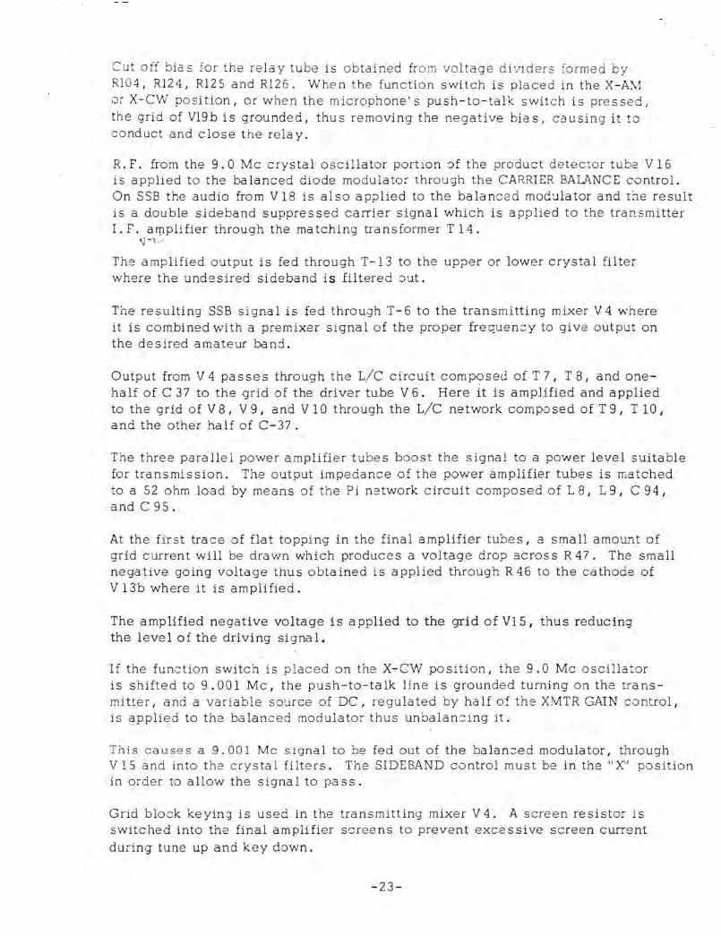
Cut off bia s for the rela y tube is obtained from voltage di viders fo rmed by RI04, R124, R125 and Rl26. When the function switch is placed in the X-A\1 or X-CW position, or when the microphone's push-to-talk switch is pressed , the grid of V19b is grounded, thus removing the negative bias, causing it t o conduct and close the relay.
R. F. from the 9.0 Mc crystal: oscillator portion of the product detector tube V 16 is applied to the balanced diode modulator through the CARRIER BALANCE control. On SSB the audio from V 18 is also ap;:>lied to the balanced mOG'Jlator and the result is a double sideband suppressed carrier signal which is applied to the transmitter I.F. arpplifier through the matching transformer T14.
\) --, ~ The amplified output is fed through T-13 to the upper or lower crystal filter where the undesired sideband is filtered iJut.
The resulting SSB signal is fed through T-6 to the transmitting mixer V 4 w here it is combined with a premixer signa 1 of the proper frequency to give output on the desired amateur band.
Output from V 4 passes through the L/c circuit composeJ of T 7, T 8, and onehalf of C 37 to the grid of the driver tube V 6. Here it is amplified and applied to the grid of V 8, V 9, and V 10 through the L/C network composed of T 9, T 10, and the other half of C-37.
The three parallel power amplifier tubes boost the signal to a power level suitable for transmission. The output impedance of the power amplifier tubes is matched to a 52 ohm load by means of the Pi network circuit composed of L 8, L 9, C 94, and C95.
At the first trace of flat topping in the final amplifier tubes, a small amO Ui'1t of grid current will be drawn which produces a voltage drop 3cross R 47. The small negative going voltage thus obtained is applied through R 46 to the cathode of V 13b where it is amplified.
The amplified negative voltage is applied to the grid of VIS I thus reducing the level of the driving signal.
If the function switch is placed on the X-CW position, the 9.0 Me oscillator is shifted to 9.001 Me, the push-to-talk line is grounded turning on the transmi tter, and a va r iable source of DC, regulated by half of the XMTR GAIN c ontrol, is applied to the balanced modulator thus unbalancing it.
This eaUS9 S a 9.001 Me signal to be fed out of the balan;::ed modulator, through V 15 and into the crysta 1 filters. The SIDEBAND control must be in the" X" position in order to allow the signal to pass.
Grid block keyin;! is used in the transmitting mixer V 4. A screen resistor is switched into the final amplifier screens to prevent excessive screen current during tune up and key down.
-23-

If the func t ion switch is placed on X-AM , the operation is the same as on X-CW except that a fixed rather than a variable DC is applied to unbalance the balanced modulator , and the s':reen modulator V 14 is switched in series with the final amplifier screens. Note that the transmitter AGC will not prevent ove rmodulation when the TR-3 is used on AM.
Whe n t he transmit/rec eive relay (Kl) is close d, either through VOX excitation or by grounding the push-to-talk line, the cathodes of V3b, V7 , V II, and V 12, are isolated from ground d~sabling th~ receiver I and the cathodes of V4 I V6, V8, V9, V10, and VIS are connected to ground to actuate the transmitter. Also the an te nna connecter is s witched from the receiver input to the final amplifier ta nk circuit.
FIG. 7
ANT
DIAGRAM - R.l. DRAKE MODEL TR- 3 SIDEBAND TRANSCEIVER
rIG. 6
20 i i
I I
FREQUENCY IN KILOCYCLES
SHIFTED CW CARRIER
~0 1L---+---~--4---~--~--++------~
40 , I
! I r, 50~--+--1-"----\--+---+--\--------1
i I / ' 1/ :
60 ' V ' i SELECTIVITY CURVE OF 9MC CRYSTAL FILTERS
-24-

VII SERVICE DATA
Iwe will check and factory align your TR-3 for a nominal fee of $10.00 P~~5
Itransportation charges if the set has not been tampered with. If rep3irs '=':-2
Inecess3ry I we will advise you of the cost before p::oceedtn9 with the wo -:<.. . IUnits that have been tampered with or misaligned will be repaired on a L:-::e and ma terial ba sis onl .
A. REMOVING TOP COVER:
iwARNING: Extreme caution should be taken when the top and bottom co\-e::s of the TR- 3 are removed. High voltage is p:-esent at several points whic::-_ could cause a lethal electrical shock! !
1. Remove the three top screws on each side of the TR-3. 2. Remove cover by first pulling up 0:1 the rear and then on the froc::>:
the cabinet.
B. REMOVING BOTTOM COVER:
1. Remove the six bottom screws from the sides of the TR-3. 2. Lift TR-3 cha ssis out of bottom cover.
C. TUBE REPLACEMENT:
In general, most trouble encountered in radio equip:nent of good design ': s due to tube failure. The TR.-3 has been designed so tha t tube replaceme:1t can be done without need for realignment. The best method of finding defective tubes is direct substitution. It is best not to rely too heavily on tube c:--_e:::ke:-s.
D. TROUBLESHOOTING:
Careful consideration has been given in the design of the TR-3 to keep maintenance problems 'to a minimum. However I it is quite possible tha: some problem will arise which cannot be cured by tube substitution. If this occurs, we suggest that you either return your unit to your dealer 0 :
write direct to our service department describing your problem in detail. Include full information concerning external connections, control settin~ S I
tubes substituted etc. Do not return equlpment to the factory without prior authorization.
The voltage and resistance charts which follow should be valuable in isolating minor problems. However I no attempt should be made to serv::e the TR-3 unless you are thoroughly familiar with electronic Gircuitry an:::: servicing technique. CARE SHOULD BE TAKEN NOT TO DISTURB THE LUD DRESS IN THE TR-3 SINCE SEVERAL CIRCUITS ARE QUITE CRITICAL IN T~2S
REGARD.
-25-

Fig 8 VOLTAGE CHART
Pin 1 2 3 4 5 6 7 8 9
VI 134 -1.44 125 0 6.3* 255 3.0 3.0 .7
V2 -6.0 0 6.3* 0 130 140 0
165 95 ~ ~L lid 11 V3 0 165 6.3* 0 250 165 11 9
0 0 12.6* 6.3* 245 165 165 V4 240 2.5
-38 1.1 56 62 1.1 V5 -0- 43 12.6* 0 145 150 43
V6 165 0 260 265 T.1 - 2.2 < 0 0 12.6* 6.3* 255 160 0
--245 100 L.l
V7 -.2 0 12.6* 0 240 120 165
V8 265 -58 140 -58 265 165 43 -76 3 0 12.6* -76 43 0 .35
V9 265 -58 140
0 12.6* -58 265
0 165
43 -76 . 9 -76 43 .35
VI 0 265 -58 ~ -58 265 165
43 -76 .9 0 12.6* -76 43 0 .35
VII -.2 0 12.6* 0 ~ ~ L.l 255 125 165 250 100 ld VIZ -.2 0 12.6* 0 --255 165 165
V13 -.1 -60 -58
12.6*- .2 -60 -56
6.3* -0- -68 -70 12.6* -66 -62
V14 265
13 13 12.6* 0 13 -.9 0 60
255 52
0 265 170 170
V15 -.1 0 12.6* 240 110 1.8
V16 -2.5 U 0 6.3*
115 150 0
-2.0 2.8 110
V17 0 7.5 12.6* 6.3* 255 165 0 250
V18 82 . 5 0 0 12.6* 133 0 1.3 6.3* -
265 -6 0 6.3* 12.6* 90 1.2 V19 190 -.5 0 N.C.
V20 150 0 0 0 150 0 0
Note: All mea surements were made with an 11 megohm VTVM and were taken from ground. RF Tu ne, Plate, and Load controls wp.re set a s described under tuning procedure. Ba nd switch was on 40 meters, Main tuning was at 7.250 Mc and Sideband was on "X". All receive measurements were made with function switch in the CAL position. Transmit mea surements were made with function switch in the X-AM position. The AC-3 power supply was used. Where two voltages are s hown, the top one is for receive and the bottom is for transmit. A * indicate s AC voltage.
-26-
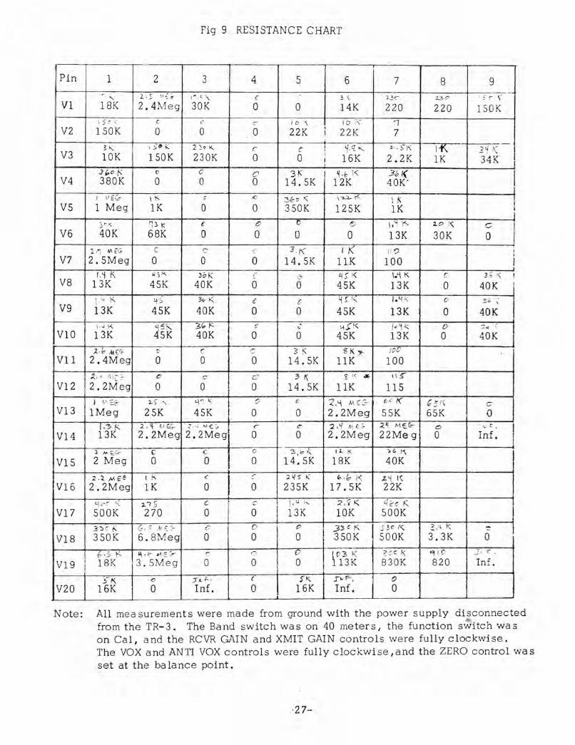
Fig 9 RESISTANCE CHART
Pin 1 2 3 4 5 6 7 8 9 ~
" 2· 5 v~ ~ \"' ,,:- \ c .) \ 23-C D O ~ ~ \' --VI 18K 2.4Meg 30K 0 0 14K 220 220 150 K
\ 5" "- C ! ,-. C ! D '\ 10 (\ 'I V2 150K 0 0 0 22K I 22K 7 !
2 ,< \ ;,-~ ;;: 2 }. I<.. I ~ ,q "'- z... S'";-\ If-.. -
-" r r: , ] ~ K V3 10K lSOK 230K 0 0 I 16K 2.2K lK 34K I .) {,.o I< t> C 0 3K i ~. & 1<: 3bl( , V4 3S0K 0 0 0 14.SK 12K 40K-
! 1..' £& \ t<. G c ~6 o i« \ '2.2.- r<. \ 1\ ! VS 1 Meg 1K 0 0 350K 12SK 1K j
} '"il(. fD \;: £ 0 0 <$ l;-q \-"-. ~C> 1" C '
j V6 40K 68K 0 0 0 0 13K 30K 0 2.'1 ", p:; C C ~ 3K II< 11 0
V7 2.SMeg 0 0 0 14.SK ,
11K 100 I f.~ K ;":~K ~bK C 6 t{S' K \.'1 K C 3 ; '\ !
V8 13K 4SK 40K 0 0 4SK 13K 0 40K i
\." K ~ i 31 ... t< c c ~ n" /. 'i i< 0 3 1; , . ~
V9 13K 45K 40K 0 0 4SK 13K 0 40K \ • \J ~'" '1.<;" • 3 " /'=. c ,; 1.-\ : '<' « ~ K 0 :? d '\ J\'..
VIO 13K 4SK 40K 0 0 4SK 13K 0 40K ), .& AI ( (9 c C c :3 K 't K "
100 1
VII 2.4Meg a 0 a 14.SK 11K 100 oZ. , I\, c::- 0 c CO
I 3 K. s I ~ ~ I LS"
V12 2.2Meg 0 0 a 14.SK 11K 115 f ~, Er.::- :l- S" :" t.\ " k, 0 1 c :(,'-\ MC(:- e e K G ~ /\ c:
V13 1Meg 2SK 4SK 0 0 2.2Meg SSK 6SK {)
J.'3 K 2 , '4, Vr{_ z. '-.i M. € ~ r 6 2. ~ Mf.~ .z ~ M E.(.,,- I:) ' ....... r . I V14 13K 2.2Meg 2.2Meg 0 0 2.2Meg 22Meg 0 Inf. I
!
1 N. ~G- (; C 0 3,"'"' \4. K .(. r, I VIS 2 Meg 0 0 a 14.SK 18K 40K
2.4,ME e- t /<. c :: I 2~ 5' K ",. ", 1<; t. 't ('i. V16 2.2Meg lK 0 a i 23SK 17.SK 22K
"lire r, 2. 7 5 c c I \ I lJ h:' ;(' .1 K 410c K V17 SOOK 270 a a I 13K 10K SOaK
3-:: C !< (,.. ~ ,{\ <: ~- c 0 I c 3 3 0 K _cy~ f<.. 3. ~ K ~
VIS 3S0K 6. SMeg 0 0 0 I 3S0K SOOK 3.3K 0 {, ,;, K ~ \ ~ "'i E Go-- c 0 0 I ~03 K
-? OO K 9 10 ..1J. r "
V19 18K ,3.SMeg 0 0 0 13K 830K 820 In£.
~-K c :r '- i' . { ';1<. I ",F, 0
V20 16K 0 Inf. 0 16K Inf. 0
Note: All measurements were made from ground with the power supply disconnected from the TR-3. The Band switch was on 40 meters, the function switch was on Cal, and the RCVR GAIN and XMIT GAIN controls were fully clockwise. The VOX and ANTI VOX controls were fully clockwise ,and the ZERO control was set at the balance point.
·27-
CAR V9 VB L8 L9 T 3 V 1 BAL C 30
~_ V16
Vl3
CI27
<Tl2
Tl4 VIO CI68 C76 KEY
VI2 T9
VIS Tll
TIO
V6
V7
T7
T8 0
V3
V4 Vl7
T6 VI8
MIC T3 u -L
T2
VI HONES
T.P.
L2 4
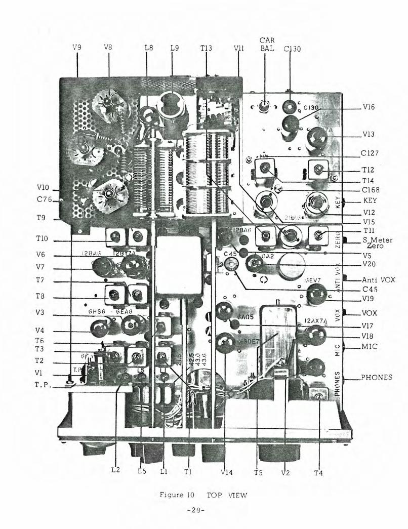
Figure 10 TOP VIEW
-28-
C IZ7
TlZ C163 KEY V1S VI2 T13
Vll 2,M, era TIl C4S
VZO
Anti VOX
V19
VOX
VIS
MIC
PHO
Ca r V13 C130V16 Bel Li ght s Tl4 V5
T4 \/ 2 T2 \/17 \/14 Tl 11
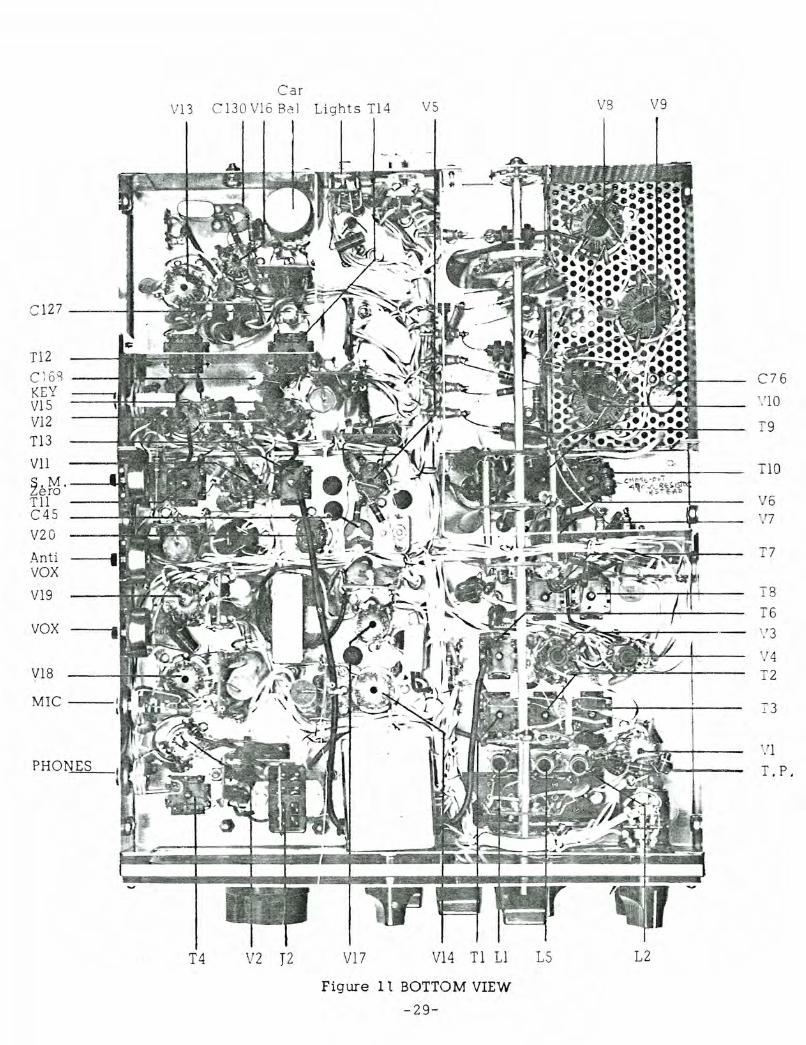
Figure 1 1 BOTTOM VIEW
-Z9-
V8 V9
C 76
. 10
T9
TlO
>/ 6 , 7
T7
1 8 T6 ,1 3
, 4
T2
T3
/l
1. P.
L5 L2
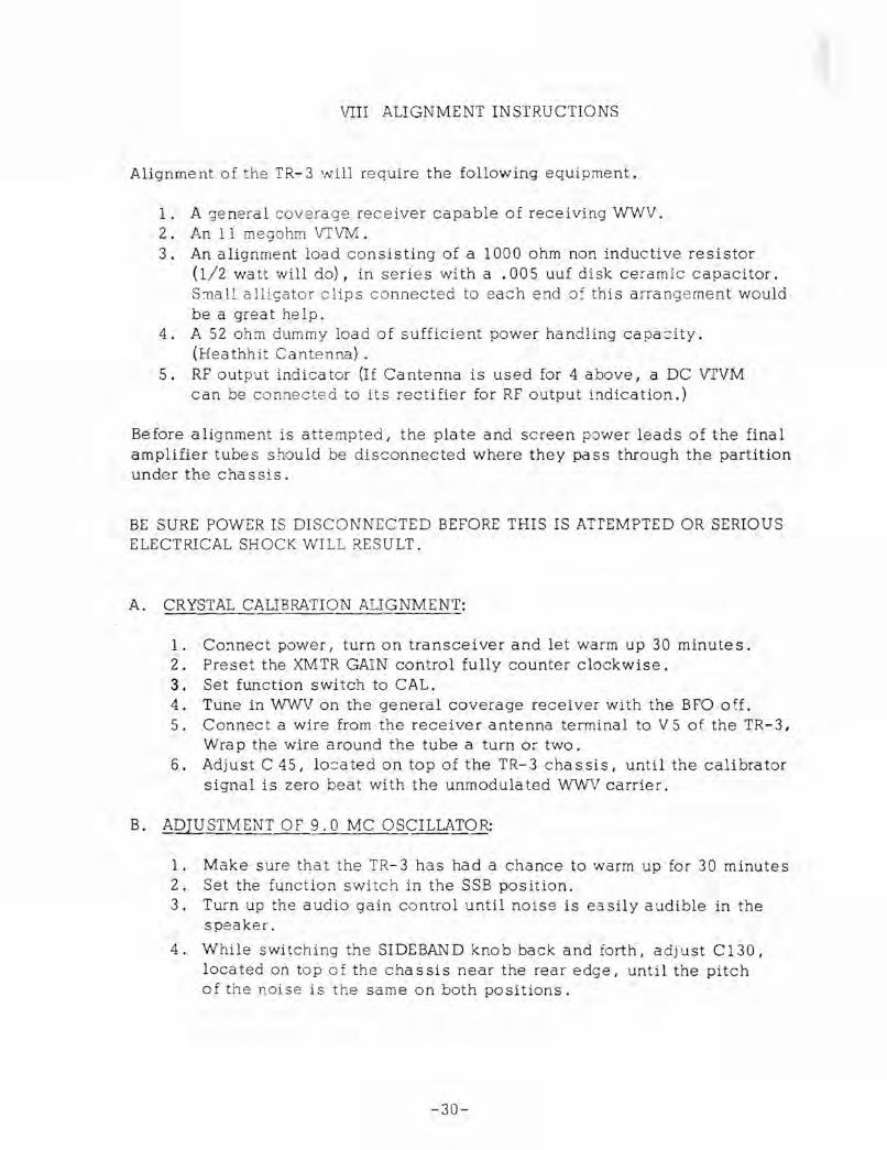
VIII ALIGNMENT INSTRUCTIONS
Alignment of the TR-3 will require the following equipment.
1. A jeneral coverage receiver capable of receiving WWV. 2. An 11 megohm VTVM. 3. An alignment load consisting of a 1000 ohm non inductive resistor
(1/2 watt will do), in series with a .005 uuf disk ceramic capacitor. S:nall alligator clips connected to each end of this anangement would be a great help.
4. A 52 ohm dummy load of sufficient power handling capacity. (Heathhit Cantenna) .
5. RF output indica tor (If Ca ntenna is used for 4 above I a DC VTVM can be connected to its rectifier for RF output indication.)
Before alignment is attempted I the plate and screen power leads of the final amplifier tubes should be disconnected where they pass through the partition under the chassis.
BE SURE POWER IS DISCONNECTED BEFORE THIS IS ATTEMPTED OR SERIOUS ELECTRICAL SHOCK WILL RESULT.
A. CRYSTAL CAUBRATION ALIGNMENT:
1. Connect power, turn on transceiver and let warm up 30 minute s. 2. Preset the XMTR GAIN control fully counter clockwise. 3. Set function switch to CAL. 4. Tune in WWV on the general coverage receiver with the BFO off. 5. Connect a wire from the receiver antenna terminal to V 5 of the TR-3,
Wrap the wire around the tube a turn or two. 6. Adjust C 45, located on top of the TR-3 chassis, until the calibrator
signal is zero beat with the unmodulated WWV carrier.
B. ADJUSTMENT OF 9.0 MC OSCILLATOR:
1. Make sure that the TR-3 has had a chance to warm up for 30 minutes 2. Set the function switch in the SSB position. 3. Turn up the audio gain control until noise is easily audible in the
speaker.
4. While switching the SIDEBAND knob back and forth, adj ust C 130, located on top of the chassis near the rear edge, until the pitch of the noise is the same on both positions.
-30-
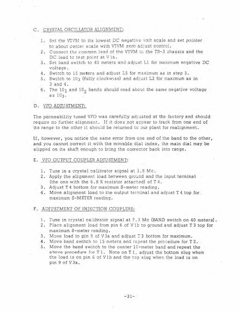
C. CRYSTAL OSCILLATOR ALIGNMENT:
1. S<.::t the vrVivl to its lowe st DC negative volt scale and set pOinter to about center scale with vrVM zero ac just control.
2. Connect the common lead of the VTVM to the TR-3 chassis and the DC lead to test point at Via.
3. Set band svl'itch to 40 meters and adjust Ll for maximum negative DC voltage.
4. Switch to 15 meters and adjust L5 for mc.ximum as in step 3. 5. Switch to 103 (fully clockwise) and ad j ust L2 for maximum as in
3 and 4. 6. The 101 and 1° 2 bands should read abou t the same negative voltage
as 1°3'
D. VFO ADJUSTMENT:
The permeability tuned VFO was carefully ad j usted at the factory and should require no further alignment. If it doe s not a ;J~ear to track from one end of it s range to the other it should be returned to ::)Ur plant for realignment.
If, however, you notice the same error from one end of the band to the other, and you cannot correct it with the movable dial index, the main dial may be slipped on its shaft enough to bring the corrector back into range.
E. VFO OUTPUT COUPLER ADJUSTMENT:
1. Tune in a crystal calibrator signal at 3.8 Mc. 2. Apply the alignment load between ground and the input tenninal
(the one with the 6.8 K resistor attached) of T 4. 3. Adjust T 4 bottom for maximum S-meter reading. 4. Move alignment load to the output terminal and adjust T 4 top for
maximum S-METER reading.
F. ADJUSTMENT OF INJECTION COUPLERS:
1. Tune in crystal ca 1.ibrator signal at 7.3 Mc (BAND switch on 40 meters). 2. Place a lignment load from pin 6 of VI b to ground and adjust T 3 top for
maximum S-meter reading. 3. Move load to pin 9 of V 3a and adjust T 3 bottom for maximum. 4. Move band switch to 15 meters and fe?eat the proc edure for T 2. 5. Move the band switch to the center l O-meter band and repeat the
above procedure for T 1. Note on T I, adjust the bottom slug when the load is on pin 6 of V Ib and the to? slug whe n the load is on pin 9 of V 3a.
-31--

G. RECEIVlNG I. F. ALIGNMENT:
1. Peak R. F. TUNE control on noise at 3.8 Mc. 2. Adjust TIl top and bottom and T12 top and bottom for maximum noise
from speaker.
H. ADJUSTME NT OF BAL.MODUlATOR OUTPUT TRANSFORMER:
1. Disconne:t power and reconnect the screen and plSite supply leads to the h n::d amplifier tube.
2. Reconnect power. 3. Connect d ummy load to antenna jack (4) .
NO ATTEMPT SHOULD BE MADE TO OPERATE THE TR-3 ON TRANSMIT UNLESS IT IS CONNECTED TO A S2 OHM LOAD. TO DO SO COULD RESULT IN SERIOUS DAMAGE.
4. Short the push-to-talk terminal of the MIC jack to ground to actuate the transmitte, .
S. With the XMTR GAIN c ontrol fully counter clockwi se and with the function switch 0:1 SSB I adj ust the CARRIER BAlANCE control to one end of its rotation. Prevent plate current from rising above .1 S amps by detuning the R. F. TU NE control.
6. Adjust T 14 for peak plate current, being careful not to exceed the .15 amps limit .
7. Readjust CARRIER BAlANCE control for minimum plate current. 8. Remove short from push-to-talk terminal.
I. FILTER MATCHING TRANSFORMERS:
1. Tune in crystal calibrator signal at 4.0 Mc and adjust main tuning so tha t changing the SIDEBAND switch from the upper to the lower sideba nd makes no difference in the S-meter reading.
2. Turn R. F. tune control counter-clockwise until S-meter reads no higher tha n S-3.
3. Once again adjust main tuning until switching SIDEBAND knob between the X and non X position makes no difference.
4. With the SIDEBAND SWITCH in its counter clockwise position I adjust T6 and Tl3 for maximum S-meter reading.
5. Repeat s t eps 2 thru 4 again for best results. 6. Center 9. Mc OSCillator as described in paragraph B.
J. CARRIER BAL.<\N CE ADJU STMENTS:
1. Turn the XMT R GAIN control fully counter clockwise I set the SIDEBAND switch on "X" I a nd turn the function switch to X-CW.
2. Adjust t he CARRIER BAL~NCE control for minimum plate current.
-32-

3. Now adjust the slug tuned ::::apa ~itor (C 127) for further null. 4. Alternately ad just these two controls until no further null can be obtained. 5. Return the fun::tion switch to the SSB position.
6. An external receiver tuned to the transmitter frequency will enable a deeper null due to its additional sensitivity.
K. ADJUSTMENT OF MIXER AND RF COILS:
1. Place BAN D switch on 80 meters. 2. Set RF tune control to 5. 3. Set function switch to CAL and tune in the calibrator signal at 3.8 Mc. 4. Adj ust T7 and T9 bottom for maxi mum S-m2ter reading. 5. Set BAND switch to 40 and RF TUNE to 7. 6. Tune in a calibrator signal at 7.3 Mc and adjust T8 and TIO top for
maximum S-meter reading. 7. Set BAND switch to 20 and RF TUNE to 5. 8. Tune in cal signal at 14.2 M c and peak T7 and T9 top for maximum
B-meter reading. 9. Set BAND switch to the center 10 meter band a nd the RF tune control to 5.
10. Set the SIDEBAND switch to X and function switch to XCW. (Tuning at 28.8Mc.)
11. Slowing rotate the XMTR GAIN from its counter clockwise position until a definite increase in plJte current is obtained.
12. Adj ust T8 and TlO bottom for a peak in plate current I being careful not to allow the plate current to rise aoove .15 amps for more than a few second s at a time.
13. Return function switch to SSg.
L. FINAL AMPLIFIER NEUTRALIZING:
1. Attach an RF output indicator between the TR-3 and the dummy load. If a Heath Cantenna is used I a vrVM can be attached to it for RF output indication.
2. Load the TR-3 on 10-meters following "Tune up procedure" . 3. While ~uning the PLATE control back and forth through resonance I
ad'just C76 until the plate current dip and maximum RF output occur simultaneously.
M. TRANSMITTING 1. F. NEUTRALIZING:
1. With microphone plugged into TR-3 I turn VOX gain fully counterclockwise and turn XMTR GAIN fully clockwise. The function switch should be left On SSB.
2. While talking into the microphone I increase RCVR GAIN until your speech can be heard from the speaker.
3. Adj ust C168 for minimum output from speaker. 4. If over one turn of adj ustment is required I it will be neces sary to
realign T14 and rebalance carrier I see paragraph Hand J.
-33-

IX AC-3 POWER SUPPLY
The R. L. Drake model AC-3 is a complete power supply capable of supplying all of the required v'Jltages for the TR-3 with the proper filtering and regulation from 120 VAC I 50/60 cycles.
It is designed to fit into either our model MS-3 matching speaker or RV-3 receiving VFO/speaker to become a single unit.
To mount it in eUhs:- of these units I remove the four :ubber feet from the botto m and slide it in fro m the rear so that the line cord and power cable face outward. Fasten it in place with the four screws which were used to hold the feet on.
To connect it to the TR':'3 I simply plug the female power connector on the end of the power cable into the male connector on the rear of the TR'-3 (See TR-3 installation instructions) .
The bias adjustment should be set properly before any operation is attempted. (See TR-3 tune up in structions). A test point is provided for ease in measuring final amp. plate current. This current in amperes is equal to the voltage at this point times 0.2. To properly set the bias voltage for 0.1 ampere idling current in the TR-3 the voite]e at this point should read 0.5 volts.
IMPORTANT: NEVER SHIP THE AC-3 MOUNTED INSIDE THE MS-3 OR RV-3 CASE OR SERIOUS DAMAGE TO THE CASE INTLL RESULT.
I i
• Red ~::)2 .. ~ .~ n
1!~~~------:'~*~1-~~-1,,~.1~~·~:~~4~:S~31~~~----~!~~~---~1~C-,~--r+--~~---, NOTE:
r- 'T' ·.~·att ti..:..j T-~~ ~;]
I~P~.::,.~~~~·_:~<~_"31_"~ .. ,~. ~I!~"·ltt~~,<,_,-c~ ,~ , I n'~ T-!- !o;~ .';' TD :-"lW'M ts L-______ +--_+_--.J .. v y'
-
'tel . 2SC
Fig. 12
-34-
Yellow
3n'1W'iT :- .... , . ..
?ower connector shown from s·:>tder connector end .
-- --=
SCHEMATIC DIAGRAM
MODEL AC-3 POWER SUPPLY
913b325.J1

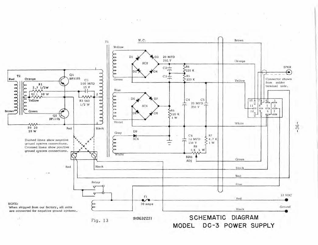
DC-3 Power Supply Instructions
The R. L. Drake model DC-3 power supply is a self contained power converter which transforms 12 VDC to the voltage neceSS:HY to operate our model TR-3 transceiver.
The converter changes the DC input power to square wave A. C. and applies it to a transformer T 1. The transformer output is rectified and filtered to provide 650 volts at 300 rna average I 500 rna peak, 250 volts at 175 ma, and -45 to -65 volts adjustable bias into 3. 33 K ohm load.
The DC-3 is normally supplied for use in cars with negative ground systems. However, it can be used with positive ground systems by making the following change.
1. Remove the four (4) sheet metal screws holdin g the cover to the power supply and remove cover.
2. Notice the two terminal barrier strip mounted on the ba se of the unit.
3. Loosen the two screws on this strip. 4. Reverse the two wires which they hold and retighten the screws. 5. Replace the cover and replace the four sheet metal screws.
CAUTION: THE TRANSISTOR CASES ON THE BOTTOM OF THE POWER SUPPLY DO NOT OPERATE AT GROUND POTENTIAL. CARE SHOUL D BE TAKEN THAT THESE TRANSISTORS 00 NOT SHORT TO THE CAR FRAME OR DAMAGE TO THE POWER SUPPLY MAY RESULT.
We recommend that the DC-3 be mounted on the passenger side of the firewall. We do not recommend that it be placed i n the trunk due to excessive primary lead length or in the engine compartment unless it is protected from water and engine heat.
To connect the DC-3, attach the short black wire to the nearest convenient ground and run the red wire through the firewall t o the ungrounded terminal of the battery, or to the" hot" terminal of the s ~ arter solenoid.
The female power cable connector is then mated to the male socket on the rear of the TR-3 and a speaker is attached to the pho ne plug on the end_of the six-inch lead protruding from the female connector.
Coil up any excess power cable and tape it in a convenient location. You may need it when you trade cars. The large red and black battery wires should be cut as short as possible to avoid unnecessary voltage drop.
The BIAS ADJ. control, located on Jhe end of the unit just above the ca ~le entrance, should be adjusted as described in the TR-3 instructions under" TU l\l: NG PROCEDURE" .
-35-
T2 Orange
10 W
Q s
I '1105
1
<:>
~
CI <!>
500 MFD C> lSr- <0< J .,..
- L; Zc> N ~
QZ Sf 11 OS
~------~~ . R9 ZO 20 W
Red
R3 560 C>
liz W C>
C>
<>
co
<>0
3 <:>
Black
~" >(
"'I " X 1 ..,
" J( • I I
0( I , yJ( .... 11< I
Dashod Unos show noqlltlvo wo und ay/Jtllrn (:onnl}c tionH. Crossed lines show positive ground system connection s.
~. ~~I
Red
NOTE: When shipped from our factory. all unit are connected for negative ground syste
T
ms •.
Black
Relay
T1 v
TI
I ')
Fig. 13
N.C.
Yellow
~ D~ ~ p
~ ~ >0 ~ Green
Blue
)c:>
>0 D~ D7 )c:>
P
~ )<~
"" P Violet
Gray D9 .. )c:> SC6
>0-:>0->0-
White
FI ... ~ ..., 30 amps
91$6322.51
r " Brown
20 MFD 350, V Oriwge
CZ* R4 SPKR Z20 K /-, £:'
" ~- - - - - \.::. C3~ >R5 > 220 K Connector show. Yellow
from solder terminal side.
C4 CS 10 7 ~b~ 20 MI'D ~ 'r' II 8 5 2 350 V '-t----'<:= = = I~ >R6 120- ~ 6
>220 K ?-= ( I W
White
C6 R7
-'- -'-II,M FD >4.7K
~ "'tJ'w --S K 5 W
BIAS Green ADJ
Black
1<ed
Illue
'-'
12 VD Red .A --
Ground Black ....
SCHEMATIC DIAGRAM MODEL DC-3 POWER SUPPLY
I 1O C"')
I
, f
I t.
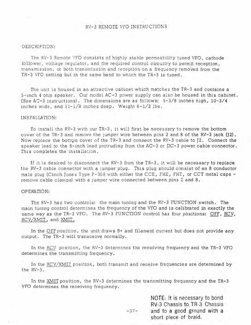
RV-3 REMOTE VfO INSTRUCTIONS
DESCRlPTION:
The RV-3 Remote VFO consists of highly stable permeability tuned VFO, cathode follower I voltage regulator, a nd the required control circuitry to permit reception, transmission, or ooth transmission and reception on a frequency removed from the TR-3 VFO setting but in the same band to which the TR-3 is tuned.
The unit is housed in an attractive cabinet which matches the TR-3 and contains a 5-inch 4 ohm speaker. Our model AC-3 p:)wer supply can a l so be housed in this cabinet. (See AS-3 instructions). The dimensions are as follows: 5-3/8 inches high, 10-3/4 inches wid2, and 11-1/8 inches deep. Weight 6-1/2 lbs.
INSTALLATION:
To install the RV-3 with our TR-3, it will first be necessary to remove the bottom cover of the TR-3 and remove the jumper wire between pins 2 and 8 of the RV-3 jack (J2). Now replace the bottQm cover of the TR-3 and connect the RV-3 cable to J2. Connect the speaker lead to the 6-inch lead protruding from the AC-3 or DC-3 power cable connector. Thi s completes the insta 11a tion.
If it is desired to disconnect the RV-3 from the TR-3, it will be necessary to replace the RV-3 cable connector with a jumper plug. This plug shou ld consist of an 8 conductor male plug (C inch Jone s Type P - 30 8 vdth either the CCE I FHE I FHT I or CCT metal caps -remove cable clamps) with a jumper wire connected between pins 2 and 8.
OPERATION:
The RV-3 ha s two controls: the main tuning and the RV-3 FUNCTION switch. The main tuning control determines the frequency of the VFO and is calibrated in exactly the same way as the TR-3 VFO. The RV-3 FUNCTION control has four positions: OFF I RCV, RCV/XMIT, and XMIT.
In the OFF position, the unit draws B+ and filament current but does not provide any output. The TR-3 will transceive normally.
In the RCV position, the RV-3 determines the receiving frequency and the TR-3 VFO determines the transmitting frequency.
In the RCV/XMIT position, both transmit and receive fre quencies are determined by the RV-3.
In the XMIT position, the RV-3 determines the transmitting frequency and the TR-3 VFO determines the receiving frequency.
NOTE: It is necessary to bond RV-3 Chassis to TR-3 Chassis
-37- and to a good ground with a short piece of braid.

SERVICE DATA
We will check and factory align your RV- 3 for a nominal fee of $ 5.00 plus transportation charges if the set has not been tampered with. If repairs are neces sary, we will advise you of the cost before proceeding with the work. Units that have been tampered with or misaligned will be repaired on a time and material basis.
A. REMOVAL FROM CABINET:
1. If the AC-3 power supply is installed in the RV-3 cabinet, it will first be necessary to remove it by removing the four screws holding it to the bottom of the RV-3 cabinet and sliding it out the rear.
2. Now loosen the six screws holding the RV-3 in the cabinet and slide it out the rear.
B. TUBE REPLACEMENT:
In general, most trouble encountered in radio equipment of good design is due to tube failure. The RV-3 has been designed so that tube replacement can be done without need for realignment. The best method of finding defective tubes is direct substitution. It is best not to rely too heavily on tube checkers.
C. TROUBLESHOOTING:
Careful consideration has been given in the design of the RV-3 to keep maintenance problems to a minimum. However I it is quite possible that some problem will arise which cannot be cured by tube substitution. If this occurs I we suggest that you either return your unit to your dealer or write direct to our service department de scribing your problem in detail. Include full information concerning external connections I control settings I tube s substituted etc. Do not return equipment to the factory without prior authoriza tion.
The voltage and resistance charts and the schematic diagram should be valuable in isolating minor problems. However I no attempt should be made to service the RV-3 unless you are thoroughly familiar with electronic circuitry and servicing technique.
D. AUGNMENT
The RV-3 is very carefully aligned at our factory and should require no further adjustment. If a tracking error in the VFO is noted I the unit should be returned to our factory.
However, if the unit has the same calibration error from one end of the dial to the other, and if the error cannot be corrected by the movable index line, the dial scale can be slipped slightly on its shaft until the. discrepancy is eliminated.
-38-
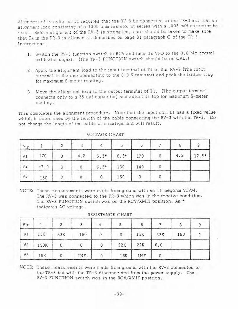
Ali gnrhe n: of tra nsformer Tl re q uires that the RV-3 be :::?nne:::ted to the TR-3 3f.:' ::-:at an al i gnment load ::;ansisting of a 1000 ohm resistor in se ries with a .005 mfd ca;:a::::tor be used. Be fo re alignment of the RV-3 is attempted, care should be tak e n to ma ke ~ l re that T4 in the TR-3 is aligne d a s described on page 31 paragraph C of the TR-3
InstructlO ns .
1. Switch the RV-3 function switch to ReV and tunc its VfO to the 3.8 Mc ::::-/sta1
ca.librator signal. (The TR-3 FUNCTION switch should be on CAL.)
2. Apply the alig nment load to the input term ina l of Tl in the RV-3 (The in;\.;.: terminal is the one conne:::t1ng to the 6.8 K resistor) and peak the lx>ttO::1 slug fo r maximum S-meterreading.
3. Move the alignment load to the output terminal of T 1. (The output termi nal connects only to a 35 uuf capacitor) and adjust Tl top for maximum S-meter
read in.;] .
This completes the alignment procedure. Note that the input coil Ll has a fixed value which is determined by the length of the cable connecting the RV-3 with the TR-3. Do n;)t change the length of the cable or misalignment will result.
VOLTAGE CHART
Pin 1 2 3 4 5 6 7 8 9
V1 170 0 4.2 6.3* 6.3* 170 0 4.2 12.6*
V2 -7.0 0 0 6.3* 130 140 0
V3 150 0 0 0 150 0 0
NOTE: These measurements were made from ground with an 11 megohm vrVM.
Pin
VI
V2
V3
The RV-3 was connected to the TR-3 which was in the receive condition. The RV-3 FUNCTION switch was on the RCV/XMIT position. An * indicates AC voltage.
RESISTANCE CHART
1 2 3 4 5 6 7 8 9
15K 3 3K 180 0 0 15K 33K 180 n ....
150K 0 0 0 22K 22K 6.0
16K 0 INF. 0 16K INF. 0
NOTE: These measurements were made from ground with the RV-3 connected to the TR-3 but with the TR-3 disconnected from the power supply. The RV-3 FUNCTION switch wa s in the RCV /XMIT position.
-39-
CI :001
C2 .005
--)
3
RI 160
+250
6
VI 12AU7A
LC3 R3 J39 J 5 'LA
HZ 33 -.i.C4 K -r-IOO
L-~ __ . _____ _ -- ------- -l
Red
TR-3 VFO CATH. Orange
XMIT CATH. Grey
Rev CATR. Yellow
I · I GND 1 I Black
~.
R4 2K 5W
,~
HS 1. 5K SW
c61 35 -r
L R7 4.7K~---- \ -AAA ____ \ R9
I I I·.
I 3.-------
C8 .005
r-- __ T2 I -I .r---~-----I I·
I
• I
Cl2 68 C13
-l I I I I I I I I I I L ______ _ - - --1- ___ __ ...
RFC
OW-3 FUNCTION] RCV
RCV XMIT --
V2
CI4
I'OOS
Dl01 Lamp ltS3
12.6 Whlt~e __________________________ ~ __ ~~ __ ~~ ____________________________ ~
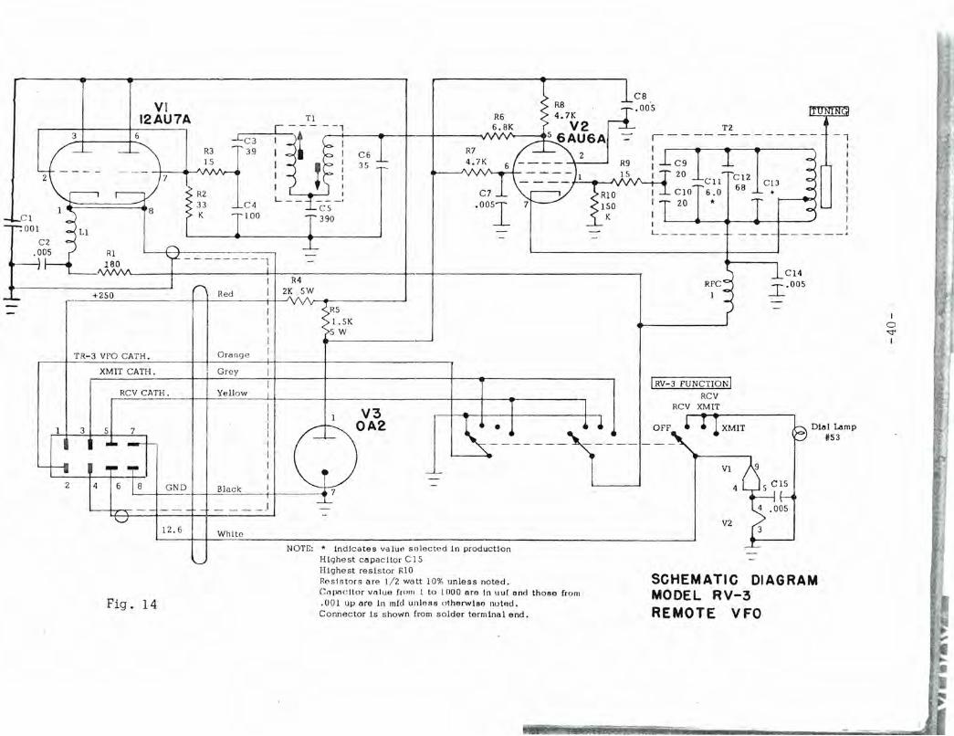
NOTE: * Indicates valutl solected In production Highest copacltor CIS
3
Fig. 14
Highest resistor RIO Re s .lsto rs are liz watt 10% unless noted. C npi1 c llo r vollJQ frolfl 1 to 1000 ora In uu[ and thoBe from .001 up are in mId unless otherwiAo Ilotod. Connector Is shown from solder terminal end.
SCHEMATIC DIAGRAM MODEL RV-3 REMOTE VFO
I o "<l" I
SAND switch viewed flvm I
_________ ~":v:n~tin~9~o~m~. e~t~e'~~ __ "_t_'o_n __ ~~~~----.----.~:s~O~R~£~G-------~3
~ . 005 R9
".7K
CI 150
Via ~l SEAS
~~~~ I
RIJr el 7 l.~ K .or ..::::r::...

------------ - -.--- - - -'r - - --,
It'M!T CATH L-----------r--------~--t__J
- 00
tlSO RfS :
_____________ ~X~M~!T~G~~~T~.~~ ____________ T_--------------------------------------------_________ .' ________________________ , l ~ . le VOLTS
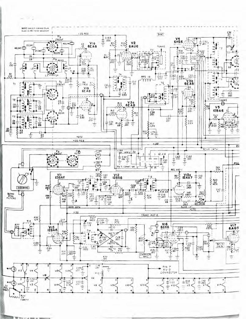
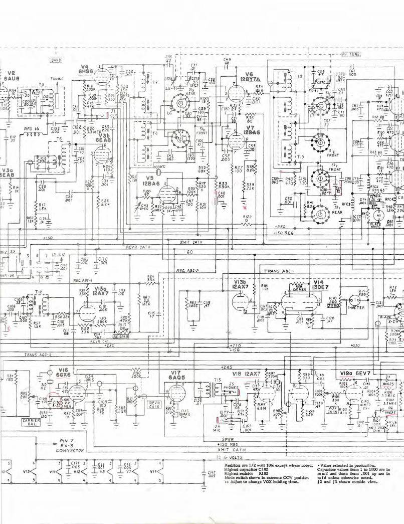
Red.KcB a:e 1/2 watt l~ ~ what! ~~.i. High£st czpacitQo C 1 B 2 High_ ...- R132 Mode ... 'iIch .how" in e:om:::.e CCW p:cItic:> •• • -\dJuit to change VOX ~ time.
• Value selected in production. Capacibx ...-alue:s &cxm 1 to lCJOC) are in m m f a.nd thcce from .001 up are in '" f d unless othel'lOi,se ooted. J 2 and J 3 lhow1l (1.'lJide view •
SCHEMATIC DIAGRAM
MODEL TR-3 SIDEBAND TRANSCEIVER 1018633001

C I ISO
RI /.SK
9.0h1C XTAL
filTERS
BAND switch viewed frv m fr ont in BO meter posit io n
I SIPEBAND I
! - ~ ~. - - -
+/50 REQ
+1
C 21 .00 1
- 1--- - -
I
~D:
o AGC- 2
PIN 7 RV-3
R 2S 2.2 K
C/63 CI62 .l00I ~ OO/
I I I I L_
R26 1.5
' RCVR (
CON Nl!crOR L-_ ___ ___ _
T - -~ - - - -- - - - ~ "- - - - - - - - -
_L_
)(M IT CATH II ________ ~------~-~- -ISO
' RCVR CATH
T -80
L+~--------+-~----_+-----------~~----~~----1_~-~
REe. .... H-2 I TRANS AGe-I
+ 5 +p<o r +150 I -RAlVc AGC-2
I i
d RBt r ISO 6~1:6 Y---.'r'I'T--__ R90 I VI7 VIS 12AX7 ~~:~7~K R99tDc, 140 VI9a 6EV7 D5 I
CJ~,t 22°Kr-~ 6AQ5 - 33 0 ODS ~JG1 l. -=- 5 .00l-IS:...-R/'. __ +-_---. I S liTIS J5 -J:::-Uit-1 G K ~i RI02 G CI+ I i ING 25- r '
M Dk~~,f y ~ : ~ ~ ~HONES --=- Ct(:'37 '~'.( 1 38 "'---'-,' 100 ' , .01 ~~ ~ . , Me m I'V 6 ... I~ 'IXl 1001 7: RIOO 7 'RIOt RI0 6 , RBS /.~ <17?.::_= .... ;;:_-n-,~ .:" L.... . _ •. _ - ,..--,z···-; ~--.- SOOK$" RIOI --./ lOOK J3MlG
eoohTc ~27~~ CIlO ~e~\~;t CIO~~ ~66K:UI RCVRI7 2 ~ ' C,151 ,-- C 1 7~ RS5; rt'~~1391 J~O 8·-/I~~fD --=- - J~~i,I ' - 8'~ MEG 2 100 R89 GAIN R92 ~..L --=- 68' 6.8M ,~7 iVOX J RI03 . 15.. D .. G
CI3 RBB 22K 270~-n/ 1J 1 C171 ..J... R94 R98 <-. RI09 lYJ1! 820 J + 1>1 625 CI3 2 RS? 001 15K L-.. ~IOM' O U'~~O I ::!: +7,K, 500<;-1 3..3K ~'---'
~-..... - I C-A- RR I[R(OI IK .... ~ 2\v Jt. K: lC.142.l~~ RR.IiI017. 7 ... 'Q R"I'"6 SAL .J... -'- J6 _C169 ....1....1 01 '1 --,00]\- 6R,
. --=- . --=- --=- - - MIG - _,~Ol --=- --=- i --=- --=- ._tJ1I~O~ _~ _
'~------~l PIN 7 I L.... ___ ~SIPn..!/(. R~, -------------+-------------------------------'---4 •• RV-3 t l50 RE G :
CO NN ccrOR L ____________________________________________ ~X~M~IT~C~A~T~H~ ____________ Tt-_-_-.-_--_-_--_--_-.--_-.-.-_--_--_--_-_-.--.-. -.- _--.-_--_-.--. -_-. 1~.1e VOLTS
CIt?
-~---~---4----~---.:..---+----'-....... - --___J. .005
Resistors ..., 1/2 watt 10% except where noted. Highest capacitor C182 Highest resistor R132 Mode switch shown in extreme CCW position .. Adjust to change VOX holding time.
'* Value selected in production. Capacitor values from 1 Ix> 1000 are in m m f and those from .001 up are in !!l f d unless othervvise noted. J 2 and J 3 shown outside view •
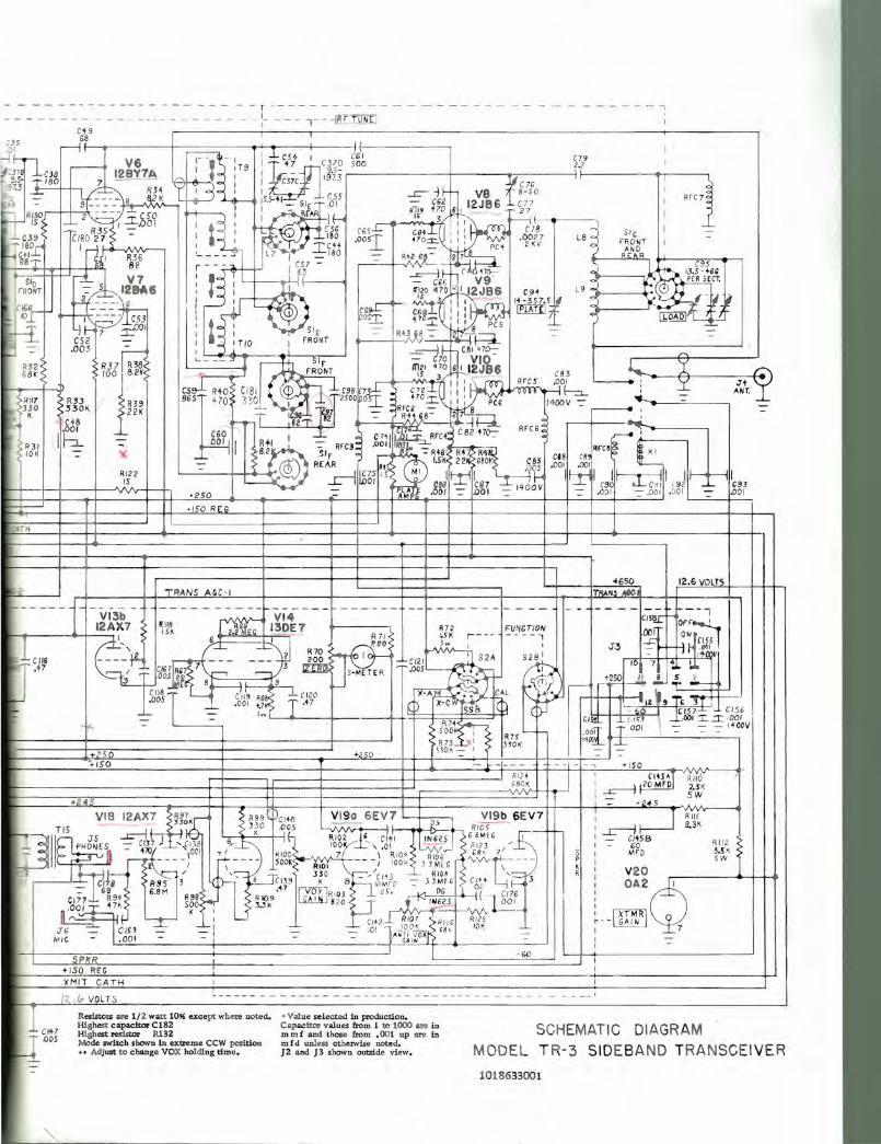
- - - - - - - - - - - - - - - - - - .- - - . - r - - - - - - - - --- - - -- - - - - - -- - - - - - - - - - - - ---- - - - - - - - -t-- - - T - -lB.I .'[Q]IJ
C+9 0 5 ----,68 .01 I---,f----.-----f-------.-+--<!..-----l---~ (------- I
-ll l-rl c--' V6 8k1- -~ - :13 liEf] -!-W I C§.~~ r~-~-6------+---___.,,_;;_---_jS:L--l-----~'--__, :J7~ .lm 12BY7A - ) I 1 3.5' T'80 7 --- iA~. : I C37C 1973 t iC 76 I i
.37.3 --L_ l /:=L- ~~4 Y I 1 I rS5 ...r=--=- C-1,,2~ i2VJ8B" C8-7570 I
ft'~ RI~ .----H-'9f-.~~~~~-~::·~ ~C·;: K L : ~:5'5-+1-=- ~fAR - oIIO~ A,'l' t~;/ 6 1 _ " 27 , : RrC7 15 L I.I..OO I I ~ 1 I.e:' 31, I I Hr-<~---l
R35 - C56 C65-1- CM .l~i~ I ' C78 SIG I -C39 CI802 7 - ': ISO .00sT '70.= : 1 1 .0027 L8 FRONT I -
~T '80r 1,-) 1 I CH ~ _' PCt 2KV ) 0
HW~ I ~j l W ~ =:= = ~ L7 : w -=- ISO -=- Rt:i - )l-~2 ~ B n (}- o..--...B.;.u.tt....,&:llR>-, t+--.---",,.-,---_----,
t-~rF=RSo~I~~Tn+=tocr±-=;t--... ,~-i-+-~,- I!~6 : : ~; i)~o m, 112~~6 It~i;7.5IJ L 9 ~ : __ ----<~:.( 1~[Et~ ~ ~Br I ~ - C§~~: I : [TIill] ~ : ~ · r
I- ()-L P- I -.::,-- C53 I ~05.I. ~~§.I. ':: 1 0 [!;@' ~
~ c~r 7 ~OOI : " : TID I r~'!NT -=- R4U8 -=- ..1~ -=- ~ r-l -=- ,005 - 1 --=---i,l;;~'~1 470::- "
R32 RJ 7 r;;;: L ___ ::r I ~~~NT m21 gg B I 1~~~6 1 Y _ 1 _ ,- :~ I 1 RrC5 .001 ~ , Y ;It
6BK 'OOl'!.~8.~2~K: .~ 15 3/ ' (83 """ ""
C~t::: RW CI SI CD '. J9S (73~ C7 2 III ' Q Q rl-:::J... J -:::- ANT.
,l R1I7 R3J R39 865 ~ 70 "\ 30 I 25001P0~ H 0 .::r::. I I : PCG 14 00V -=- "'~-____ -=-_ _ ---, 330 330K 22K - - _ Tc97 RfCC - 8 ~ ,
K C48 ..,T I : 1'2 -=- Rtl'S- 27--1 ~ r---t-- ' 1 ,- I '~ CSO 't::' 1
82.J::: ' iI C7+1~ R;C 4~ CB2 Ha::- AFCS! ~m'
RJ I I--:J.... -::-, LQ.Q.!j j ~+I -=- RrCJ~ ,001 I~ .c~; RfCS~ 10K -=- r 1 8.2 Sir" '---~R+B Rn R4~ CSB C8 F KI
-=--- a\ R[ AR RH 1.5 K 2 2~ G80K C 6~ ,001 .001
RI22 - ~ --.J le75 IS "" I ~ I '\'L I ~ I 11---.----1 I I I IS ,2S0 ~ 11.001 ,&~~ '~ ' ~~i -=- 1400V '~ •. &~? ' ~.g6~ ,o6f l -=- ,g~
' ISO REG
' TH 1 _____ -+-----+- +---
TRANS AGe'I
+ 5 +250 +150
+2' .
~650 12.6 VOLTS
---- - ----- - - ------ --I CIsq[: Ol'f~' m r- -- F'V~t T/OIi 001 OW
- - - - : J3 I~ II (ISS
SlS ' - I ~,fQV /-!) 10 7 l.I. "" +-250 I t.!.., !.. ~
~ \ If. ,---'rr- - 1 --
I~ J ! ,J ,.J'"LD 1--ef>] - . ~ ICl57~ CI56 ClltL (.I~:? -,-,001 _r.:1'_· 001
[ -r 001 -=- -=- -=- ItOOV R7S c- .001 . 1 330< I'lf/!) _ I-=-
- -, + ISO
RHO 2.S K 5 W
VI 8 12AX7 ~gJKr R99 (~CI 40 VISa 6EV7 VI9b 6EV7
~IIT~' 5 J5: ~J-rf'-i ~ J~O .0;0!l5 ~i clt l 1::251, Jtd~lG I --- PHONE,oSU -=- ~~'lJ , ---,-' { I0.10B, G/'-,~ 100 ' , .0 1 w~ ?~!82.3 ,1'_ - 1 7; HIOO 7 'RIO; ROG • ill.' ,..---,l---- ' r;-- -- - 500~S--R'OI ---I lOOK 33 'Ml. "vVv-t---- -- I L...... / '0::-:: ~1 33 0 - '/(115 - - RIO ~ ''::: ,---'.---'- d~ RS, 3 ~~TCi3~ K 8 'OMr Q -=- J3 Mf bl~ C/),+ I-e 3
i ~t~ 1 - 60
MrD
V20
' I!;:·~rd\
R 112 3.5 K sw
I I~ I -I -
- 68 SSM .'17 IVOX ] 1 15". DG "i. C~)6 . CI77 R94 . R98 <:-. R 109 lG..6J1l.. ~'f6 J • ''''61l. J _OOI_ '~Ol 4 7K 5~O(-: 3..3K v... ,.-. -~;:~ JJ I I . col RIO T R ' RI25 u..:..=::;:: 1, _'--- -L 14"-=- lOOK le6 10K
J6 _ C I69 - ~ : - _ 01 11".n~~?fR ' M.C - .001 - -- I - - --j' ---"-~ ______ _ _ -_-'
SPIr R -GO
+150 REG .XMIT C ATH
1~.f., VOL TS , - - - -
Resistors are 1/2 watt 1096 except where noted. Highest capacitor C182 Highest resistol R1 32
• Value selected in production. Capacitor values from 1 to 1000 are in mmi and those from .001 up are in mid unless otherwise noted.
SCHEMATIC DIAGRAM Mode switch shown in extreme CCW position •• Acijust to change VOX holding time. J 2 and J3 shown outside view. MODEL T R- 3 SIDEBA ND TRANSCEI VE R
1018633001

, '.