Embed Size (px)
Citation preview

INSTRUCTION MANUAL
ETD1000 REMOTE ELECTRONIC TANK DISPLAY
FOR
TMS SERIES TANK MANAGEMENT SYSTEMS
This document describes the installation, programming and operation of the ETD1000 Remote Electronic Tank Display, which is designed for use with any TMS2000, TMS3000, or TMS4000 Tank Management System.
DWG NO. 20035 REV. A


Page Section 1.0 PRODUCT OVERVIEW ........................................................................................ 5
1.1 TMS Compatibility ................................................................................................. 6 1.2 Display Data .......................................................................................................... 7 1.3 Display Messages ................................................................................................. 7 1.4 Alarm LEDs ........................................................................................................... 7 1.5 Audible Annunciator .............................................................................................. 8
Section 2.0 INSTALLATION ..................................................................................................... 9
2.1 Mounting ................................................................................................................ 9 2.2 Wiring .................................................................................................................. 13 2.2.1 AC Power ............................................................................................................ 13 2.2.2 Communications .................................................................................................. 14 2.2.2.1 Cable Requirements ............................................................................................ 14 2.2.2.2 ETD1000 Terminal Connections ......................................................................... 15 2.2.2.3 ETD1000 Communications Wiring Detail ............................................................ 15 2.2.2.4 TMS Communications Wiring Detail .................................................................... 15 2.2.2.5 Line Termination Resistor ................................................................................... 16 2.2.2.6 TX1064-1 Wiring Detail ....................................................................................... 17
Section 3.0 CONFIGURATION .............................................................................................. 19
3.1 On-Board Programming ...................................................................................... 19 3.1.1 Setting Logical Address - S3 ............................................................................... 19 3.1.2 Dipswitch Settings - S4 ....................................................................................... 20 3.2 Front Panel Programming ................................................................................... 21 3.2.1 Programming Procedure ..................................................................................... 22
Section 4.0 FRONT PANEL OPERATION - OPERATOR MODE .......................................... 25 Section 5.0 PRODUCT SPECIFICATIONS ............................................................................ 27
TABLE OF CONTENTS


ETD1000 Instruction Manual - 2017-07-01.docx Page 5 of 28 July 1, 2017
1.0 Product Overview The ETD1000 Electronic Tank Display panel is used in applications where it is desired to view TMS series tank management data from various on-site locations at distances up to 4000 feet (1200M) away from the main console. Since the ETD1000 is a microprocessor-based, addressable device communicating over the TMS RS-485 Peripheral Expansion Bus, up to 16 ETD1000 panels may be connected to a single TMS. Unlike the TD1000 Tandem Remote Display, each ETD1000 may be operated independently. The ETD1000 is housed in a NEMA 4X enclosure for harsh industrial/ outdoor environments. The display technology employs an ultra-bright, truly sunlight-readable LED display for maximum reliability in extreme temperatures. The membrane overlay pushbuttons are one inch on centers for easy operation with gloved hands.
Figure 1.0-1 Front Panel View
DRAWING NO. 20023 REV. A
TESTSELECTTANKMODE
TANK ID
LiquidLevelC ontrol SystemsPNEUMERCATOR
ETD1000 ELECTRONICTANK DISPLAYGAL
ULL
%GAL
°F
IN
SP 2
WATER
SP 3
SP 1
LEAK

ETD1000 Instruction Manual - 2017-07-01.docx Page 6 of 28 July 1, 2017
Figure 1.0-2 Interior View
1.1 TMS Compatibility The ETD1000 can be used with any TMS2000, TMS3000, or TMS4000 provided appropriate firmware is loaded. ETD1000 support is provided with the following TMS console firmware versions;
Vxx.99.90 thru Vxx.99.99 Vxx.00.xx Vxx.01.xx Vxx.02.xx
where “xx” denotes “don’t care” values
Please contact Technical Support for an upgrade if you have firmware outside of the above range, or if you have questions about identifying the TMS firmware version in your console.
DWG NO. 20031 REV. A
68
71
54
32
DISPLAY CABLECONNECTOR
J1 DISPLAY
1/2 AMP250 VACFASTACTING
GND
NEUTRAL
HOTACIN
115V
D2D3
AUTO OFFTMS FP ACKAUDIBLECONTROL
EDIT ENABLE
S3
S4
LOGICALADDRESS
12345678
OUT
IN
RS-485 COMMS.CH. A (+)CH. B (-)SHIELD
ON
OFF
LINE TERMINATOR
"ON" FOREND-OF-RUN ONLY
TB2 T B3
S2
(2) LEDS
LINE TERMINATORSWITCH
(2) RS-485 COMMS.PLUG-IN TERMINAL
BLOCKS
ROTARYSWITCH
DIPSWITCH
FUSE
LINE VOLTAGESWITCH
AC POWER PLUG-IN TERMINAL BLOCK(W/ SCREW FLANGE TO SECURE PLUG)
+ 3.3 V + 5 V
OP
EN
COMM ALARMMOTION DSPD. PT. CTL
IMPORTANT! Confirm that the installed TMS console firmware version supports ETD1000 communications.

ETD1000 Instruction Manual - 2017-07-01.docx Page 7 of 28 July 1, 2017
1.2 Display Data The seven-segment LED display shows the selected Tank ID along with the selected tank data as defined in the table below. User-selected tanks and display modes may be enabled or disabled. Refer to Section 3.2 Front Panel Programming for details on this feature.
Display Mode Data Format* Display Units Gallons DDDDDDD Gallons (Liters)
Net Gallons DDDDDDD Gallons (Liters) Percent Gallons DDD.d % of Capacity
Ullage DDDDDDD Gallons (Liters) Product Level DDDD.d Inches (mm) Water Level uDDDD.d Inches (mm)
Product Temperature sDDD.d F (C) *Where: d = Tenths, s = Signed Data, u = Water Symbol
1.3 Display Messages The seven-segment display indicates a limited number of messages as follows;
Display Message Description-No data- No communications with TMS
nn Lo Prod Tank level below gaugeable limit nn ------ Probe timeout or sync error
tank name User-selected Tank Name where nn = Tank ID
The “tank name” message is displayed when the MODE pushbutton is momentarily activated, as described in Section 4.0 ETD1000 Front Panel Operation
1.4 Alarm LEDs Alarm LEDs are provided to annunciate tank-related alarms as follows;
Alarm LED DescriptionLeak In-Tank Leak Test FailureSP1 Product Setpoint #1 (HighHigh 95%) SP2 Product Setpoint #2 (High 90%) SP3 Product Setpoint #3 (Low 20%)
Water Water Setpoint (Above 2”/51mm) Factory default values in ( )

ETD1000 Instruction Manual - 2017-07-01.docx Page 8 of 28 July 1, 2017
1.5 Audible Annunciator
A front panel audible annunciator is provided both to annunciate tank or communications alarm conditions, and as an audible confirmation aid when navigating using the membrane pushbuttons. Under alarm conditions, the beep rate of the annunciator varies with the alarm type as follows;
Alarm Beep RateLeak Fast (50ms)SP1 Medium Fast (100ms)SP2 Medium Slow (200ms)SP3 Slow (400ms)
Water Slow (400ms) ms = milliseconds

ETD1000 Instruction Manual - 2017-07-01.docx Page 9 of 28 July 1, 2017
2.0 Installation The ETD1000 is designed for both indoor and outdoor installation. If the unit is to be installed outdoors, the installer must pay attention to local code requirements for outdoor conduit runs containing AC line voltage.
2.1 Mounting The ETD1000 is designed for wall mounting using the four mounting holes as shown in Figure 2.1-1. Mounting hole placement is made easy using supplied 1:1 scale mounting template in Figure 2.1-2. Note that these mounting holes are outside of the gasketed interior of the enclosure and therefore do not affect weatherproof performance.
Figure 2.1-1
DRAWING NO. 20025 REV. A
1 916 [39]
578 [149]
7 332 [180]
32132 [93]
1316 [20]
3 58 [92]
778 [200]
512 [140]
DIMENSIONS: INCHES [MM]
21332 [61]
3 1516 [100]
AC POWERCONDUITOPENING
COVERSHOWNFOR REF.
(4) MOUNTINGSCREWS
SCREWANCHOR
(4)MOUNTING
HOLES
Ø78 [Ø22] HOLE TYP. 2 PLS.
FOR 1/2" NPT WATERTIGHT FITTINGOR METRIC EQUIVALENT
COMMUNICATIONSCONDUIT OPENING
2 332 [53]
WARNING! This device is designed for Ordinary Location, Non-Hazardous installation only, as defined by Underwriters Laboratories (UL) and the National Electrical Code (NEC). DO NOT install where flammable vapors may be present.

ETD1000 Instruction Manual - 2017-07-01.docx Page 10 of 28 July 1, 2017

ET
D1000 Instruction M
anual - 2017-07-01.docx
Page 11 of 28
July 1, 2017
Figure 2.1-2 M
ounting Tem
plate
DRAWING NO. 20024 REV. N/C
7 332 [180.0]
32132 [93.0]
USE (4) #10 X 2 " LENGTHMOUNTING SCREWS
(3/8" MAX. SCREW HEAD DIA.)
DIMENSIONS: INCHES (MM)

ETD1000 Instruction Manual - 2017-07-01.docx Page 12 of 28 July 1, 2017
ETD1000 Instruction Manual - 2017-07-01.docx Page 13 of 28 July 1, 2017
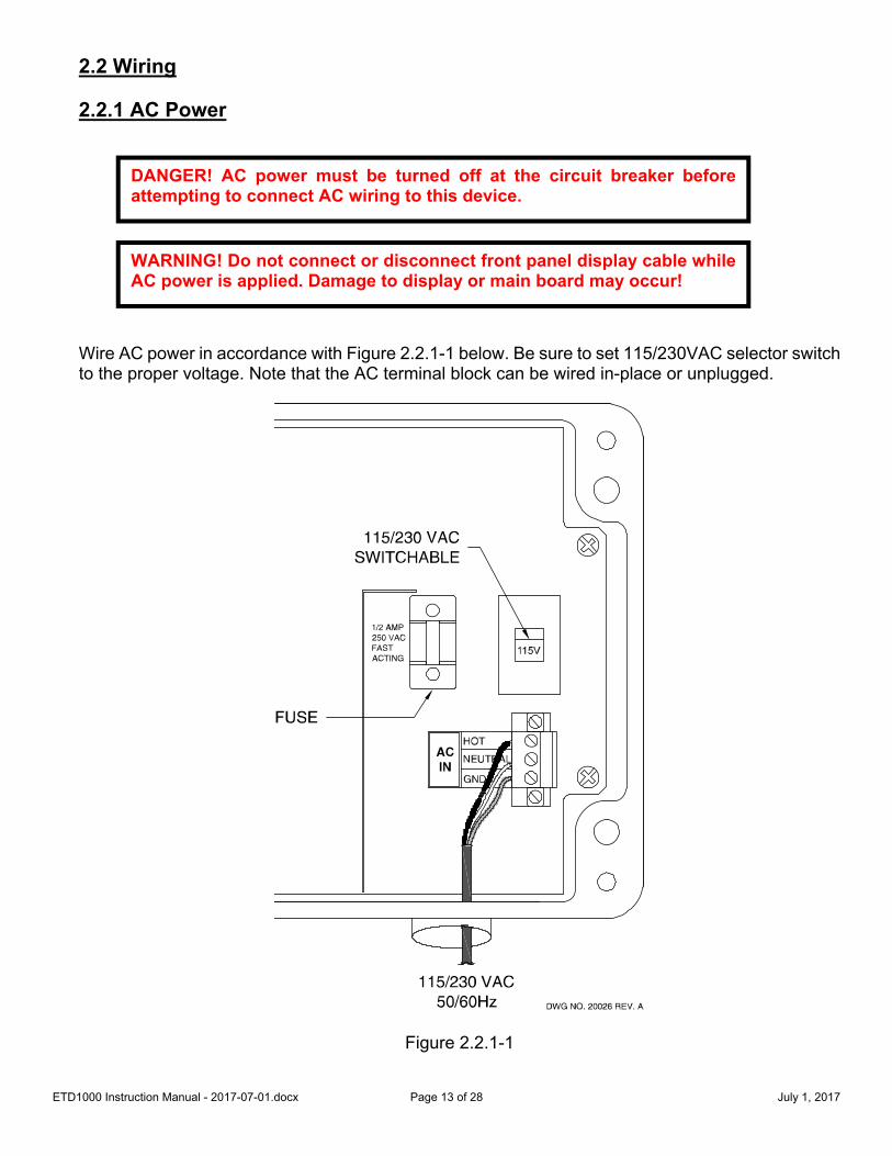
2.2 Wiring 2.2.1 AC Power Wire AC power in accordance with Figure 2.2.1-1 below. Be sure to set 115/230VAC selector switch to the proper voltage. Note that the AC terminal block can be wired in-place or unplugged.
Figure 2.2.1-1
DWG NO. 20026 REV. A
NEUTRAL
115/230 VACSWITCHABLE
115V
115/230 VAC50/60Hz
ACIN
HOT
GND
1/2 AMP250 VACFASTACTING
FUSE
DANGER! AC power must be turned off at the circuit breaker before attempting to connect AC wiring to this device.
WARNING! Do not connect or disconnect front panel display cable while AC power is applied. Damage to display or main board may occur!

ETD1000 Instruction Manual - 2017-07-01.docx Page 14 of 28 July 1, 2017
2.2.2 Communications The ETD1000 supports an RS-485 multi-drop cabling topology as illustrated in Figure 2.2.2-1 below. Maximum cable distance from the TMS console to the furthest ETD1000 is 4000 feet (1200M).
Figure 2.2.2-1 Communications Topology
2.2.2.1 Cable Requirements
Cable type should be 24AWG, single twisted pair, shielded, designated for RS-485 communications having a nominal impedance of 120 ohms. Recommended Cables: -4 to 176F (-20 to 80C) Operation* - Belden 9841 or equivalent -94 to 392F (-70 to 200C) Operation* - Belden 89841 or equivalent *See Section 5.0 Product Specifications for Operating Temperature range limits of the ETD1000.
DWG NO. 20027 REV. B
PNEUMERCATORLiqu id Lev el Cont ro l Syst em s
ETD 1000 ELECTRONIC TANKDISPLAY
ACPOWER
ELECTRONIC TANKDISPLAYETD 1000
PNEUMERCATORLiqu id Lev el Cont ro l Syst em s
JUNCTION BOX
END-OF-RUNETD1000 OR RA400
#2#1TMS
4000 FEET (1200 M) MAX. DISTANCE
PNEUMERCATORLiqu id Lev el Cont ro l Systems
TANKMANAGEMENT SYSTEMTMS
ETD1000 OR RA400ETD1000 OR RA400
PNEUMERCATORLiqu id Le ve l Cont ro l Syst em s
REMOTEANNUNCIATORRA 400
PNELiqu id Leve
REMOTEANNUNCIATORRA 400
ACPOWER
ACPOWER
ELECTRONICTANK DISPLAYETD 1000
PNELiqu id Lev e
REMOTEANNUNCIATORRA 400
IMPORTANT! Use only recommended RS-485 communications cable or manufacturer’s DOCUMENTED equivalent.

ETD1000 Instruction Manual - 2017-07-01.docx Page 15 of 28 July 1, 2017
2.2.2.2 ETD1000 Terminal Connections Plug-in terminal blocks TB2 and TB3 are provided for connection to the RS-485 TMS Expansion Bus. Both input and output terminals are provided to support multi-drop wiring to additional ETD1000s or other TMS expansion bus peripherals.
2.2.2.3 ETD1000 Communications Wiring Detail See Figure 2.2.2.3-1 below.
Figure 2.2.2.3-1 ETD1000 Communications Wiring 2.2.2.4 TMS Communications Wiring Detail Current version TMS2000, TMS3000, and TMS4000 consoles have the same type of plug-in terminal connector and wiring designations as the ETD1000, as illustrated in Figure 2.2.2.4-1 below. Previous versions have a 6-pin modular jack, as illustrated in Figure 2.2.2.4-2 below. If the board type is a previous version and was indicated on the order to the factory, the ETD1000 is shipped with a modular-jack-to-terminal-connector adapter, also shown in Figure 2.2.2.4-2.
DRAWING NO. 20033 REV. N/C
OUT
IN
RS-485 COMMS.CH. A (+)CH. B (-)SHIELD
3BT2BT
DWG NO. 20028 REV. A
WHT/BLBL/WHTSHD
END-OF-RUN
"ON"FOREND-OF-RUN ONLY
LINE TERMINATOR
OFF
ON
SHIELDCH. B (-)CH. A (+)
RS-485 COMMS.IN
OUT
WHT/BLBL/WHT
SHD
1/2" NPT FITTINGAND CONDUIT(EACH ETD1000/RA400)
TO TMS RS-485COMMS.
"OFF" POSITIONTO ADD ANOTHER
ETD1000/RA400
2 CONDUCTOR SHIELDEDRS-485 COMM. CABLE
"ON"FOREND-OF-RUN ONLY
LINE TERMINATOR
OFF
ON
SHIELDCH. B (-)CH. A (+)
RS-485 COMMS.IN
WHT/BLBL/WHT
SHD
"ON" POSITIONFOR LAST
ETD1000/RA400
OUT

ETD1000 Instruction Manual - 2017-07-01.docx Page 16 of 28 July 1, 2017
Figure 2.2.2.4-1 TMS Communications Connection, Current Version Boards
Figure 2.2.2.4-2 TMS Communications Connection, Previous Version Boards 2.2.2.5 Line Termination Resistor The RS-485 bus requires that the end-of-run device be terminated with a 120-ohm resistor. This is accomplished by setting the LINE TERMINATION switch to “ON” if the selected ETD1000 is the last device on the bus. Otherwise this switch should be set to “OFF”.
DRAWING NO. 20030 REV. B
RS-485 COMMS.3 POSITIONTERMINAL BLOCK
3/4" NPTFITTING AND
CONDUIT
1/2" NPTFITTING ANDCONDUIT
RS-485 COMMS.3 POSITIONTERMINAL BLOCK
– – OR – – TMS3000/TMS4000TMS2000
ISG
ND
GN
D
NEU
T
ISG
ND
HO
T
ISG
ND
GN
D
NEU
T
ISG
ND
HO
T
RS-485COMMUNICATIONS I/O
CH. B (BL/WHT)SHD(SHIELD)
CH. A (WHT/BL)
CH. B (B
L/WHT)
CH. A (W
HT/BL)
SHD(SHIEL
D)
RS-485COMMUNICATIONS I/O
DRAWING NO. 20029 REV. A
OR
RS-485 COMMS. 6 POS. TELCOMODULAR CONNECTOR
TMS 3000TMS 2000
ISG
ND
GN
D
NE
UT
ISG
ND
HO
T ISG
ND
GN
D
NE
UT
ISG
ND
HO
T
CONTACT PNEUMERCATOR TECHNICALSUPPORT AT (800) 209-7858 FOR ABOARD UPGRADE.
NOTE
DRAWING NO. 20034 REV. AS2
"ON" FOREND-OF-R UN ONLY
LINE TERMINATO R
OFF
ON

ET
D1000 Instruction M
anual - 2017-07-01.docx
Page 17 of 28
July 1, 2017
2.2.2.6 TX
1064-1 Wirin
g D
etail S
ee Figure 2.2.2.6-1 below
.
Figure 2.2.2.6-1 T
X1064-1 W
iring Detail
NOTES:1. THE 115/230 VAC SWITCH MUST BE SET TO 115V FOR 115 VAC OPERATION OR 230V FOR 230 VAC OPERATION.2. THIS NOTE APPLIES TO ETD1000 INTERFACE WITH TX1064-1 ONLY: FOR PROPER OPERATION, THE TX1064-1 UNIT MUST BE POWERED UP EITHER PRIOR TO OR SIMULTANEOUSLY WITH THE ETD. THIS CAN BE ACHIEVED AUTOMATICALLY BY POWERING THE TX1064-1 UNIT FROM THE SAME CIRCUIT BREAKER AS THE ETD.3. THE TX1064-1 IS TYPICALLY INSTALLED BESIDE THE ETD (WITHIN 50 FEET). CONSULT FACTORY FOR INSTALLATION ABOVE 50 FEET.
SHIELDCH. B (-)CH. A (+)
RS-485 COMMS.IN
OUT
OFF
ONCLK
DATA
GND
SHD
TX1064
Ø1.375/Ø35 MMHOLE FOR 1" NPTOR EQUIVALENTCONDUIT FITTING
GRN
RED
BLK & WHTSHIELD
SH
D
GN
D
DA
TA
CLK
TX1064-1 - EXPANSION MODULE (SEE NOTE 3)
115V
HOT
GND
NEUTRALACIN
SEE NOTE 1
RELAYCARD INSTALLED HERE
RELAY I/Os
OP
EN
23
41
SW1
IA0-3IA1-3IA2-3SPARE
SPAREIA2-3IA1-3IA0-3
SW1
14
32OP
EN
DIP SWITCHFACTORYSETTINGS
CLOSED
CLOSEDCLOSED
OPENED
ETD1000(PARTIALLY SHOWN)
22 AWG/.762 MM 4-CONDUCTORSHIELDED TWISTED PAIRS CABLE
BELDEN P/N 8723 (PVC JACKET) OR EQUIV.PROVIDED BY CUSTOMER, SEE NOTE 3
115/230 VAC50/60Hz(SEE NOTE 2)
SH
D
GN
D
DA
TA
CLK
GRNREDBLK & WHTSHIELD
Ø.875/Ø22 MM HOLE FOR1/2" NPT OR EQUIVALENT
CONDUIT FITTINGTYP. 3 PLS.

ETD1000 Instruction Manual - 2017-07-01.docx Page 18 of 28 July 1, 2017

ETD1000 Instruction Manual - 2017-07-01.docx Page 19 of 28 July 1, 2017
3.0 Configuration The ETD1000 provides user-programmable features that allow the operator to alter display and audible alarm operation as well as control interaction with the TMS for remote alarm acknowledgement. Some of these programmable features are available through the front panel pushbuttons, others via on-board dipswitches. No programming is required at the TMS console. 3.1 On-Board Programming 3.1.1 Setting Logical Address – S3 The TMS series console has the ability to individually address up to sixteen (16) ETD1000 remote displays. Rotary dipswitch S3 is used to select unique addresses for each ETD1000 connected to the same TMS. Note that address order is not important.
Table 3.1.1-1 S3 Assignments
DRAWING NO. 20037 REV. A
S3
LOGICALADDRESS
S3 ETD1000 Address Select
Device Address
0 1 1 2 2 3 3 4 4 5 5 6 6 7 7 8 8 9 9 10 A 11 B 12 C 13 D 14 E 15 F 16

ETD1000 Instruction Manual - 2017-07-01.docx Page 20 of 28 July 1, 2017
3.1.2 Dipswitch Settings – S4
Audible Shutoff Delay: If set to NONE, audible alarm will continue until acknowledged on front panel pushbuttons. If set to ONE MINUTE, audible alarm will continue until acknowledged on front panel pushbuttons or one minute has elapsed, whichever comes first. Front Panel (FP) Acknowledge Settings: If set to LOCAL, front panel acknowledgement will only silence local ETD1000 audible alarm. If set to LOCAL and TMS, both ETD1000 and TMS audible alarms will be silenced. Audible Alarm Mode: If DISABLED, audible will not activate for any condition. If set to DISPLAYED TANK ONLY, audible alarm will activate only if unacknowledged alarms apply to the currently displayed tank. If set to ALL TANKS, audible alarm will activate for unacknowledged alarms from any enabled tank. Decimal Point Control: This setting controls placement of decimal points for U.S. and METRIC units of measure. It does not perform conversions. This switch should be set to correspond to the TMS units of measure and the overlay insert on the ETD1000 front panel. Motion Symbol Display: The MOTION symbol “_” appears directly to the right of the tank ID to indicate movement of product in the displayed tank. This status is detected by the TMS and sent to the ETD1000 for display, if enabled. Refer to the TMS Operations Manual for more information. Loss of Communications Alarm: When ENABLED, an audible alarm accompanies the “No data” message if communications between the TMS and ETD1000 has failed for more than 10 seconds. Front Panel Configuration Edit: This switch must be set to ENABLE if front panel programming is required. Once programming is complete, the user can DISABLE editing and close the ETD1000, thereby reducing the possibility of unauthorized changes.
DRAWING NO. 20036 REV. A
D. PT. CTLMOTION DSPCOMMALARM
OP
EN
87654321
S4
EDIT ENABLE
CONTROLAUDIBLETMS FP ACKAUTO OFF
23
45
17
86

ETD1000 Instruction Manual - 2017-07-01.docx Page 21 of 28 July 1, 2017
Table 3.1.2-1 S4 Assignments
S4Function Position(s) Mode
Audible Shutoff Delay 1 *Closed = NONE Open = ONE MINUTEFront Panel Ack. 2 *Closed = LOCAL Open = LOCAL and TMS
Audible Alarm Mode 3,4
3 Closed, 4 Closed = DISABLED 3 Open, 4 Closed = DISPLAYED TANK ONLY 3 Closed, 4 Open = ALL TANKS *3 Open, 4 Open = ALL TANKS
Decimal Pt. Control 5 *Open = U.S. Closed = METRICMotion Symbol “_”
Display 6 *Open = DISABLE Closed = ENABLE
Audible Alarm for Loss of Communications
7 *Closed = DISABLE Open = ENABLE
Front Panel Configuration Edit
8 *Closed = DISABLE Open = ENABLE
*Factory Default
3.2 Front Panel Programming Front panel programming allows the user to specify which tanks, alarms and display modes, i.e. gallons, inches, etc., are to be made available to the operator. For example, a user could limit the operator to display a single tank in a multi-tank system, limit alarms to selected setpoints, and further limit the operator to a single mode of display, for example, gallons only. The ETD1000 is shipped from the factory with all available tanks, alarms and display modes enabled. Note that tanks that are not enabled on the TMS are automatically disabled on the ETD1000 and therefore do not require any programming to disable them. For security purposes, an on-board dipswitch is provided to enable or disable front panel programming. See Section 3.1 for details. Programmed settings are stored in non-volatile memory that requires no batteries, and therefore will remain intact indefinitely with or without AC power.

ETD1000 Instruction Manual - 2017-07-01.docx Page 22 of 28 July 1, 2017
3.2.1 Programming Procedure
View
View Tank Contents:Press and release MODE
Change Displayed Units:Hold MODE until one beep
View DifferentTank Number:Press and releaseTANK SELECT
Enable / DisableAutocycleTank Number:HoldTANK SELECT until one beep
Note
Capital Letters represent ETD display.Lower case letters added for clarity.
Reverse textindicates the following:Name of the programming section.Explanation of display.Section-specific navigation instructions.
Closed shapes indicate names ofMenus while open brackets indicatenames ofValues.
VIEWACCESSWhile holding the Test button, hold the Mode button until LOG is displayed.
SYSTEM TESTWhile holding the Test button, all internal visual and audible annunciators are tested.
ETD Navigation FlowchartETD1000 Firmware V20.06
ETD1000W Firmware V10.14
Programming Instructions
Change Currently DisplayedValue*:Press and releaseTEST
Exit and Save Changes:Navigate past all settings as instructed
*EDIT ENABLE switch must be set to allow changes
Relay 16 TANKRelay 16 ALARM
Relay 2 TANKRelay 2 ALARMRelay 1 TANKRelay 1 ALARMREL AY TIME delayed shuto ffNORMAL LYREL AY MODEShows Current Value for displayed Relay SettingAdvance to next Relay Setting by holding MODE until one beepwater ( WATER led)sp3 (SP3 led)sp2 (SP2 led)sp1 (SP1 led)leak (LEAK led)temperature (TEM P led)water level (W & LEVE L led)product level (LEVE L led)ullage (UL L led)percent volume (%VO L led)net volume (VO L and TEM P led)gross volume (VO L led)display MODE ENaBLeShows Units or Alarm LED(s) and YES/NOAdvance to next Display Mode by holding MODE until one beeptank channel 12 enable
tank channel 3 enabletank channel 2 enabletank channel 1 enableTANK ENaBLeShows Tank Channel Number and YES/NOAdvance to next Tank Channel by holding TANK SELECT until one beep
REMINDER: Dipswitch S4-8 must be set to ENABLE for front panel programming. See Section 3.1 for details.

ETD1000 Instruction Manual - 2017-07-01.docx Page 23 of 28 July 1, 2017
Table 3.2.1-1 Front Panel Programming
Display Function Mode Tank # Enable *YES/NOGross Volume Enable *YES/NONet Volume Enable *YES/NOPercent Volume Enable *YES/NOUllage Enable *YES/NOProduct Level Enable *YES/NOWater Level Enable *YES/NOProduct Temperature Enable *YES/NOIn-Tank Leak Alarm Enable *YES/NOSP1 Alarm Enable *YES/NOSP2 Alarm Enable *YES/NOSP3 Alarm Enable *YES/NOWater Alarm Enable *YES/NONormally *OFF/ONRelay Timer *NONE/1-9 MINUTES Relay # Alarm LEAK/SP1/*SP2/SP3/WATER Relay # Tank *NO/1-12
*Factory Default

ETD1000 Instruction Manual - 2017-07-01.docx Page 24 of 28 July 1, 2017

ETD1000 Instruction Manual - 2017-07-01.docx Page 25 of 28 July 1, 2017
4.0 Front Panel Operation – Operator Mode
Alarm LEDs* Display Mode LEDs
LEAK – In-Tank Leak GAL – Gross Volume (Gal/Ltr)Net Volume (with ºF/ºC LED on)
SP1 – Above 95% (High High)** %GAL – Percent of Capacity
SP2 – Above 90% (High)** ULL – Ullage Vol (Gal/Ltr, Default 90%)
SP3 – Below 20% (Low)** IN – Product Level (in/mm)Water Level (with “u” symbol, in/mm)
WATER – Above 2”** ºF – Product Temperature (ºF/ºC)
Front Panel Buttons
MODE TANK SELECT TESTPress to display tank name. Press to select tank Press to testPress and hold until beep Press and hold until display andto select display mode beep for autoscan horn
* If an alarm LED is blinking, an active tank alarm is present on a tank(s) not currently being displayed. Whenan alarm LED is on continuously, it applies to the currently displayed tank. Note that this alarm may apply tomore than one tank, which can be determined by viewing each tank with the TANK SELECT button.** Factory defaults shown. Other values and may be programmed.
Audible AlarmAcknowledgment
To silence an alarm,press any of the buttons.The visual indicator willremain active as long asthe alarm conditionpersists.

ETD1000 Instruction Manual - 2017-07-01.docx Page 26 of 28 July 1, 2017

ETD1000 Instruction Manual - 2017-07-01.docx Page 27 of 28 July 1, 2017
5.0 Product Specifications
Dimensions: 7.9” W x 5.5”H x 3.5”D Weight: 8 lbs Operating Temperature: -40º to +160º F (-40º to +70º C) Humidity: 95% Non-condensing Enclosure Construction: Cast Aluminum, Epoxy Powder Coat Paint Finish, Gasketed Cover w/Captive SS Screws Enclosure Rating: NEMA 4X, Watertight and Corrosion-proof Power Requirements: 115 / 230 VAC Switchable, 50-60Hz, 5W Max. Audible Alarm: 100db Display: 9-Character, Ultra-Bright Sunlight-Readable LED Display, 0.56” Ht, Readable from 25’
Ultra-Bright Intensity Alarm LEDS, Visible from 75’ Display Data: Gross/Net Volumes, Percent Volume, Ullage, Product Level, Water Level, Product
Temperature, Tank Name, Tank ID, Tank Alarms LED Display Mode Indicators: Volume, Percent Volume, Ullage, Product Height, Water Height, Product Temperature LED Alarm Indicators: In-Tank Leak, Three Product Setpoints, Water Setpoint Communications: TMS Series Peripheral Expansion Bus Communications Format: RS-485, Half-Duplex Connection Type: Plug-In Terminal Block with Wire Entries
Input: Ch. A (+), Ch. B (-), Shield Output: Ch. A (+), Ch. B (-), Shield
Recommended RS-485 Cable: Belden 9841 (PVC Jacket), 89841 (FEP Teflon Jacket) or similar Maximum Cable Length: 4000 Feet/1200 Meters total to end of run Slave Address Select: 1 thru 16, Rotary Dip Switch Selectable Display Update Rate from TMS: 400 to 600 milliseconds (0.4 to 0.6 seconds)