Embed Size (px)
Citation preview
Instruction Manual Multifunctional Module for Ball Valve Type 546 DN 65–DN 100
GMST6005_4_s33_48.indd 33 14.3.2007 9:49:43 Uhr

34�
The�technical�data�is�not�binding�and�not�an�expresslywarranted�characteristic�of�the�goods.�It�is�subject�to�change.�Please�consult�our�General�Conditions�of�Supply.
GMST6005_4_s33_48.indd 34 14.3.2007 9:49:44 Uhr

� 35
Table of Contents
� � � Seite1.� General�Information�� 36� 1.1�Hazard�notices� 1.2�Abbreviations2.�� CE�Marking�� 373.�� Manufacturer’s�Declaration�� 374.�� Intended�Use�� 385.�� Safety�Information�� 38� 5.1�Due�Care�Required�of�Operator� 5.2�Special�Hazards� 5.3�Transport�and�Storage6.�� �Mounting�the�Multifunctional�Module�� 41�
on�the�Ball�Valve7.�� Technical�Features�� 45
GMST6005_4_s33_48.indd 35 14.3.2007 9:49:44 Uhr

36�
1. General Information
1.1 Hazard notices
Hazard�notices�are�used�in�this�manual�to�warn�youof�possible�injuries�or�damages�to�property.�Pleaseread�and�abide�by�these�warnings�at�all�times!
Meaning
Imminent acute danger!Failure�to�comply�could�result�in�death�or�extremely�serious�injury.
Possible acute danger!Failure�to�comply�could�result�in�serious�injury.
Dangerous situation!Failure�to�comply�could�lead�to�injury�or�damage�to�property.
1.2 Abbreviations
Type�546 Ball�Valve�Type�546
MF�handle Lockable�multifunctional�handle
MF�module Multifunctional�module
PN Nominal�pressure
The�Planning�Fundamentals�referred�to�in�the�textmay�be�obtained�from�your�sales�company�or�onthe�Internet�at�www.piping.georgfi�scher.com
Warning symbols
Danger
Warning
Caution
GMST6005_4_s33_48.indd 36 14.3.2007 9:49:45 Uhr

� 37
2. CE Marking
� Warning
According�to�EC�Directive�97/23/EC�pertaining�topressure�equipment,�complete�valves�$�DN�65–DN�100�are�CE-certified.
AttentionSingle�components,�spare�parts�and�complete�valves$�DN�08–DN�20�may�not�be�CE�marked.�Singlecomponents�and�spare�parts�must�be�tested�by�thecustomer�himself�following�completion.
3. EC Manufacturer’s Declaration
The�manufacturer:�Georg Fischer Piping SystemsLtd, 8201 Schaffhausen (Switzerland),�declaresthat�the�MF module�is�not�a�ready-to-use�machine�in�the�sense�of�the�EC�Directive�concerning�machines�and�cannot�therefore�meet�all�the�requirements�of�this�directive.Operation of the MF module is prohibited untilconformity of the entire system into which thevalve with the MF module has been built is estab-blished according to the EC Directives listed below.
Applicable�EC�Directives:72/23�� EEG�� EC�Low�Voltage�Directive89/336�� EEG�� �EC�Directive�on�Electromagnetic�
Compatibility
Modifi cations to the MF module which affecttechnical data given in this instruction manualand its intended use, in other words any signi-cant alterations to the MF module, render thismanufacturer’s declaration null and void.
GMST6005_4_s33_48.indd 37 14.3.2007 9:49:45 Uhr

38�
When�mounted�on�the�Ball�Valve�Type�546,�theMultifunctional�Module�serves:•���to�signal�the�CLOSED�or�OPEN�position�of�the�valve�via�an�electric�signal�to�a�control�supplied�by�the�customer
•���as�an�interface�when�mounting�an�electric�or�pneu-matic�actuator
•��as�assembly�interface�for�fitting�the�multifunctional�lever�with�indexing,�without�signalling�position
It�is�important�that�the�given�electrical�data,�such�asvoltage�and�current�load,�are�strictly�observed.
The�MF�module�is�not�intended�for�uses�other�thanthose�stated�here.�If�the�instructions�contained�in�this�manual�are�not�complied�with,�the�manufacturer�is�excluded�from�all�liability�for�the�above�men-tionedproduct.
5. Safety Information
Any�person�in�the�company�who�is�involved�withthe�assembly,�disassembly,�reassembly,�installation,operation�or�maintenance�(inspection,�service�andrepair)�of�this�MF�module�must�have�read�and�un-derstood�this�complete�instruction�manual,�in�parti-cular�this�section�on�safety�information.We�recommend�having�this�confi�rmed�in�writing.
Remember:•���The�MF�module�may�only�be�installed�in�perfect�working�order�and�these�safety�guidelines�must�always�be�observed.
4. Intended Use
Warning
GMST6005_4_s33_48.indd 38 14.3.2007 9:49:46 Uhr

� 39
•��Only�qualifi�ed�and�authorized�personnel�may��perform�work�on�the�MF�module
•��According�to�the�Machine�Directive�98/37/EC��(formerly�89/392/EEG),�this�MF�module�is�not��considered�a�machine;�it�may,�however,�be�built�into�an�installation�which�is�considered�as�such.
Making�certain�that�these�points�are�observed�is�theresponsibility�of�the�piping�system�engineer/installerand�the�operator�of�such�systems,�into�which�thevalve�is�built.
5.1 Due Care Required of the Operator
The�MF�module�described�herein�was�designed�and�manufactured�with�consideration�to�the�respective�harmonized�European�standards.�It�corresponds�to�the�latest�technology�and�the�technical�data/features�contained�under�Section�7.
Safety�on�the�job�can,�however,�only�be�realized�ifthe�operator�warrants�that
•��the�instruction�manual�and�the�manual�of�the��corresponding�valve�have�been�read�and�under-stood�and�that�the�instructions�contained�therein�are�adhered�to,�and
•��the�necessary�measures�against�electronic�effects�have�been�taken.
5.2 Special Hazards
Under normal conditions, the MF module may only be operated with the cover closed. If work is performed on the MF module with the cover removed, the supply and control voltage must first be disconnected. Adjustments which need to be done in the energized state should be done with special insulated tools.
�
�� Warning
�� Warning
GMST6005_4_s33_48.indd 39 14.3.2007 9:49:46 Uhr

40�
In addition, the operating instructions of themanual valve must also be observed.They are an integral component of this manual.
If�connected�improperly,�especially�if�the�connec-tion�voltage�is�wrong,�the�built-in�limit�switches�canbecome�damaged,�and�if�signalization�of�the�valvefails,�considerable�damage�can�be�caused�to�thesystem.The�multifunctional�module�must�also�be�protectedfrom�mechanical�infl�uences;�it�is�not�permitted�touse�the�ball�valve�with�or�without�the�mounted�MFmodule�and/or�actuator�as�a�step�ladder.
Permanent�exposure�to�strong,�aggressive�chemicalsubstances�is�prohibited.
5.3 Transport and Storage
The�MF�module�must�be�handled,�transported�andstored�with�care.�Please�note�the�following�points:
•��The�MF�module�should�be�transported�and/or��stored�in�its�original�unopened�packaging.
•���The�MF�module�must�be�protected�from�harmful�physical�infl�uences�such�as�dust,�heat�(humidity).
•��It�is�important�that�the�connections�are�neither�damaged�by�mechanical�nor�thermal�infl�uences.
•���Prior�to�installation,�the�MF�module�should�be�inspected�for�transport�damages.�Damaged�MF�modules�must�not�be�installed.
Warning
GMST6005_4_s33_48.indd 40 14.3.2007 9:49:46 Uhr

� 41
6. Mounting the Multifunctional Module on the Ball Valve
Immediately�prior�to�installation,�inspect�the�MF��module�for�transport�damages.�We�recommend��leaving�the�MF�module�in�its�original�packaging��until�you�are�ready�to�install�it.The�MF�module�has�been�fitted�ex�works�with�the�respective�switches�and�function-tested!It�is�not�necessary�to�remove�the�cover�when�used�with�the�hand-operated�ball�valve.
Design�of�the�MF�module�with�built-in�switches
1�Housing2�Housing�cover3�Switching�disc*4�Stainless�steel�Torx�screws5��Connector�plug�3P�+�E�per�DIN�EN�175301-803*�formerly�DIN�43650)6�Coupling
*)��for�MF�module�versions�with�pre-assembled�microswitches
The�MF�module�can�be�mounted�on�the�ball�valve�type�546�in�the�opened�or�closed�ball�position.
Attention! The stem is asymmetrical.
The position of the pin must be identical with the illustration.
GMST6005_4_s33_48.indd 41 14.3.2007 9:49:47 Uhr

42�
It�must�be�ensured�that�the�ball�is�in�the�open�position.
Note�the�asymmetrical�recesses�(c)�of�the�stem.
Next�insert�the�supplied�coupling�in�the�stem�and�tap�it�with�a�rubber�mallet�until�it�is�securely�fixed�down�on�the�stem.
Ensure�that�the�two�bevels�are�parallel�with�the��angular�contour.�The�horizontal�slot�on�the�top�of�the�square�surface�indicates�the�position�of�the�hole�in�the�ball.
GMST6005_4_s33_48.indd 42 14.3.2007 9:49:49 Uhr
� 43
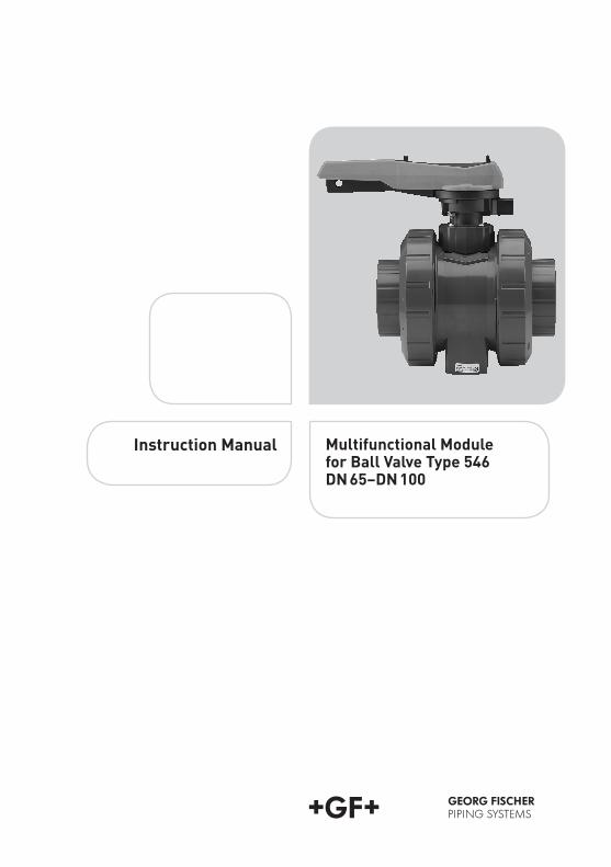
Additional�information�for�the�Multifunctional�Module�with�switches:Assemble�the�Multifunctional�Module�by�holding�both�thumbs�on�the�switch�disc.
Placing�the�Multifunctional�Module�on�the�ball�valve.��Ensure�that�the�orientation�with�the�square�(a)�and�round�(b)�contours�is�correct.�The�Multifunctional�Module�can�be�assembled�only�in�one�position.
Tighten�the�four�screws�supplied�(max�torque�4�Nm)
�
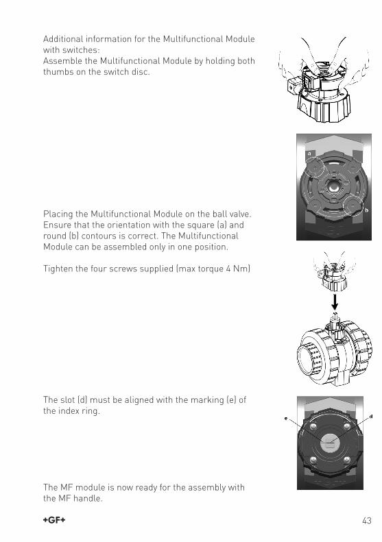
The�slot�(d)�must�be�aligned�with�the�marking�(e)�of�the�index�ring.
The�MF�module�is�now�ready�for�the�assembly�withthe�MF�handle.
GMST6005_4_s33_48.indd 43 14.3.2007 9:49:51 Uhr
44�
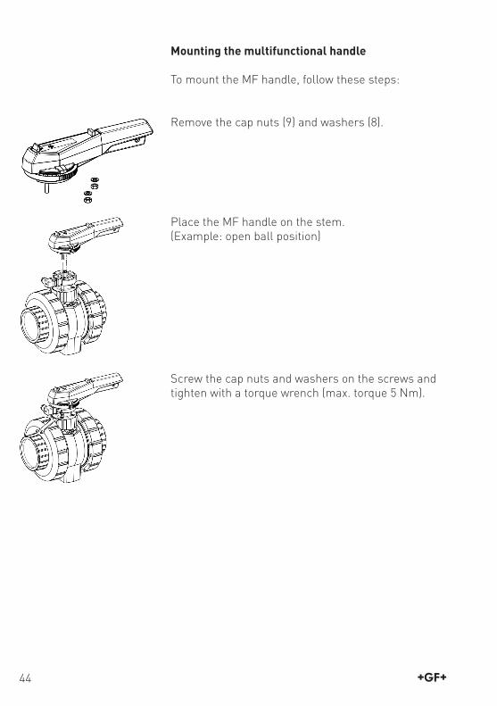
Mounting the multifunctional handle
To�mount�the�MF�handle,�follow�these�steps:
Remove�the�cap�nuts�(9)�and�washers�(8).
Place�the�MF�handle�on�the�stem.(Example:�open�ball�position)
Screw�the�cap�nuts�and�washers�on�the�screws�and�tighten�with�a�torque�wrench�(max.�torque�5�Nm).
GMST6005_4_s33_48.indd 44 14.3.2007 9:49:52 Uhr

� 45
7. Technical features – multifunctional module for type 546 DN 65–DN 100
Functions:•��Interface�for�mounting�actuators•��Feedback�unit�in�combination�with�actuators•��Also�for�manual�valves�–�with�multifunctional�handle
a) The�body�is�made�entirely�of�reinforced�polypropy-lene.�It�is�screwed�directly�on�the�valve.�The�internal�contour�of�the�multifunctional�module�is�asymmetric�and�fits�exactly�on�the�corresponding�outer�contour�of�the�ball�valve�body.
b) There�is�a�choice�of�5�cast�limit�switches.�Please�note�the�following�table�when�making�a�selection�of�the�relevant�switches.
c) The�multifunctional�module�is�screwed�directly�on�the�ball�valve�body�with��4�stainless�steel�Torx�screws.
d) The�index�ring�of�PP-H�ensures�the�precise�switching�point.
e) Appliance�plug�3P+E�for�rapid�and�simple�fitting�of�cable�–�protection�class:�IP65.
f) Coupling�of�stainless�steel�for�optical�indication�of�open/closed�ball�position�and�for�reliable�transmission�of�torque�from�the�drive�or�from�the�multifunctional�lever.
g) Cover�plate�of�polypropylene�to�protect�switches�from�water�splashes�and�dust.
� ��
Configuration of Multifunctional Modules on Ball Valve 546 DimensionDN 65 and DN 80
DimensionDN 100
Coupling
Multifunctional��module�with�pre-fitted�limit�switching
GMST6005_4_s33_48.indd 45 14.3.2007 9:49:53 Uhr

46�
Design of the Multifunctional Moduleincluding Switches
1�Housing2�Cover3�Switching�disc4�Microswitch�«OPEN»5�Microswitch�«CLOSED»6��Connector�plug�3P�+�E�per�DIN�EN�175301-803�(formerly�DIN�43650)
7�Seal�����
General Technical Dataof the Multifunctional Module
Protection�rating�with�DIN�plug�(7):�IP�65Protection�rating�with�cable�gland:�IP�67Ambient�temperature:�–10�°C�to�+50�°C
Switch type Capacity Code no.Microswitchsilver�nickel�(Ag�Ni)
250�V�~�6�A�*) 167�482�630167�482�631
DN�65–DN�80DN�100
Microswitch�with�gold�contact(Au)
4�–�30�V=1�–�100�mA
167�482�639167�482�640
DN�65–DN�80DN�100
�* ohm resistive load* For inductive load, provide for protective circuit!�
�A�closedB�openC�blackD�blue�(short�cable)E�blue�(long�cable)
Wiring�diagram
GMST6005_4_s33_48.indd 46 14.3.2007 9:49:54 Uhr

� 47
Switch type Capacity Code no.Inductive�switch�NPN
5–30�V�=�0,1�A 167�482�657167�482�658
DN�65–DN�80DN�100
Inductive�switch�PNP
5–30�V�=�0,1�A 167�482�666167�482�667
DN�65–DN�80DN�100
�
Switch type Capacity Code no.Inductive�switch�Namur�Approvals:�ATEX�2023x,�CSA�EMC�per�EN�60947-5-2Norm�conformityEN�60947-5-6
8�V�= 167�482�675167�482�676
DN�65–DN�80DN�100
�
Wiring�diagram
Wiring�diagram
NPNPNP
A�closedB�openC�blueD�blackE�blackF�brown
A�closedB�openC�blueD�brown
GMST6005_4_s33_48.indd 47 14.3.2007 9:49:55 Uhr

161�484�995GMST 6005/1,2,4,3a (03.07)©�Georg�Fischer�Piping�Systems�LtdCH-8201�Schaffhausen/Switzerland,�2006Printed�in�Switzerland
AustraliaGeorge�Fischer�Pty�LtdUnit�1,�100�Belmore�RoadRiverwood�NSW�2210�AustraliaPhone�+61(0)2/9502�8000�[email protected]
Austria�Georg�Fischer�Rohrleitungssysteme�GmbH3130�HerzogenburgPhone�+43(0)2782/856�[email protected]
Belgium / LuxembourgGeorg�Fischer�NV/SA1070�Bruxelles/BrüsselPhone�+32(0)2/556�40�[email protected]
BrazilGeorge�Fischer�Ltda04795-100�São�PauloPhone�+55(0)11/5687�[email protected]
ChinaGeorg�Fischer�Piping�Systems�Ltd�Shanghai�Pudong,�Shanghai�201319Phone�+86(0)21/58�13�33�33�[email protected]
Denmark / IcelandGeorg�Fischer�A/S2630�TaastrupPhone�+45�(0)70�22�19�[email protected]
FranceGeorg�Fischer�SASBP�88026�Villepinte95932�Roissy�Charles�de�Gaulle�CedexPhone�+33(0)1�41�84�68�[email protected]
GermanyGeorg�Fischer�GmbH73095�Albershausen�Phone�+49(0)7161/[email protected]
IndiaGeorg�Fischer�Piping�Systems�Ltd400�076�MumbaiPhone�+91�224007�[email protected]
ItalyGeorg�Fischer�S.p.A.20063�Cernusco�S/N�(MI)Phone�+3902/921�[email protected]
JapanGeorg�Fischer�Ltd556-0011�Osaka,�Phone�+81(0)6/6635�[email protected]
Korea Georg�Fischer�Piping�Systems#902�Ace�Techno-Tower�|||197-48,�Guro-dong,�Guro-guSeoul�152-050�KoreaPhone�+82�2�851�3861/3862Fax� +82�2�851�[email protected]
MalaysiaGeorg�Fischer�(M)�Sdn.�Bhd.47500�Subang�JayaPhone�+60�(0)3-8024�[email protected]
MexicoGeorg�Fischer�S.A.�de�C.V.Apodaca,�Nuevo�LeonCP66636�MexicoPhone�+52�(81)1340�8586Fax� +52�(81)1522�8906
Middle EastGeorge�Fischer�Piping�Systems�Dubai,�United�Arab�Emirates�Phone�+971�4�289�41�20�[email protected]�www.piping.georgfischer.com
NetherlandsGeorg�Fischer�N.V.8161�PA�EpePhone�+31(0)578/678�222�[email protected]
NorwayGeorg�Fischer�AS1351�Rud�Phone�+47(0)67�18�29�[email protected]
PolandGeorg�Fischer�Sp.�z�o.o.02-226�Warszawa�Phone�+48(0)22/313�10�50�[email protected]
RomaniaGeorg�Fischer�Piping�Systems�Ltd020257�Bucharest�-�Sector�2Phone�+40(0)21/230�53�[email protected]
RussiaGeorg�Fischer�Piping�SystemsOffice�14a,�3�Entrance,�9�FloorBusiness�Center�Parus1st�Tverskaya-Yamskaya�Street,�23Moscow�125047Tel.�+7�495�258�60�[email protected]
SingaporeGeorge�Fischer�Pte�Ltd528�872�SingaporePhone�+65(0)67�47�06�[email protected]
Spain / PortugalGeorg�Fischer�S.A.28046�MadridPhone�+34(0)91/781�98�[email protected]
Sweden / FinlandGeorg�Fischer�AB12523�Älvsjö-StockholmPhone�+46(0)8/506�775�[email protected]
SwitzerlandGeorg�Fischer�Rohrleitungssysteme�(Schweiz)�AG8201�SchaffhausenPhone�+41(0)52�631�30�[email protected]
TaiwanGeorg�Fischer�Piping�Systems2F,�No.�88,�Hsing�Te�RoadSan�Chung�CityTaipei�Hsien,�Taiwan�(R.O.C.)Phone�+886�2�8512�2822Fax� +886�2�8512�2823
United Kingdom / IrelandGeorge�Fischer�Sales�LimitedCoventry,�CV2�2STPhone�+44(0)2476�535�[email protected]
USA / Canada / Latin America / CaribbeanGeorge�Fischer�Inc.Tustin,�CA�92780-7258Phone�+1(714)�731�88�00�Toll�Free�800/854�40�[email protected]
Export�Georg�Fischer�Piping�Systems�(Switzerland)�Ltd.8201�SchaffhausenPhone�+41(0)52-631�30�26Fax� +41(0)52-631�28�[email protected]
GMST6005_3_s49_64.indd 64 14.3.2007 9:49:06 Uhr