Embed Size (px)
Citation preview

Form HK 830
03-08-2004
INSTRUCTION MANUAL
MODEL 353, 354 and353-78PNEUMATIC INSTALLATION UNITS


353 Series Tooling Alcoa Fastening Systems
SAFETY
This instruction manual must be read with particularattention to the following safety guide lines, byany person servicing or operating this tool.
1. Safety Glossary
WARNINGS - Must be understood
to avoid severe personal injury.
CAUTIONS - show conditions that will dam-age equipment and or structure.Notes - are reminders of required proce-
dures.
Bold, Italic type and underlining - empha-
sizes a specific instruction.
2. Huck equipment must be maintained in a safe
working condition at all times and inspected on a
regular basis for damage or wear. Any repair
should be done by a qualified repairman trained
on Huck procedures.
3. Repairman and Operator must read manual prior
to using equipment and understand any Warning
and Caution stickers/labels supplied with equip-
ment before connecting equipment to any pri-
mary power supply. As applicable, each of the
sections in this manual have specific safety and
other information.
4. See MSDS Specifications before servicing the
tool. MSDS Specifications are available from
you Huck representative or on-line at
www.huck.com. Click on Installation Systems
Division.
5. When repairing or operating Huck installation
equipment, always wear approved eye protec-
tion. Where applicable, refer to ANSI Z87.1 -
1989
6. Disconnect primary power source before doing
maintenance on Huck equipment.
7. If any equipment shows signs of damage, wear,
or leakage, do not connect it to the primary
power supply.
8. Make sure proper power source is used at all
times.
9. Never remove any safety guards or pintail
deflector.
10. Never install a fastener in free air. Personal
injury from fastener ejecting may occur.
11. When using an offset nose always clear spent
pintail out of nose assembly before installing the
next fastener.
12. If there is a pinch point between trigger and
work piece use remote trigger. (Remote trig-
gers are available for all tooling).
13. Do not abuse tool by dropping or using it as a
hammer. Never use hydraulic or air lines as a
handle. Reasonable care of installation tools by
operators is an important factor in maintaining
tool efficiency, eliminating downtime, and in pre-
venting an accident which may cause severe
personal injury.
14. Never place hands between nose assembly and
work piece.
15. Tools with ejector rods should never be cycled
with out nose assembly installed.
16. When two piece lock bolts are being used
always make sure the collar orientation is cor-
rect. See fastener data sheet of correct posi-
tioning.
�
Product complies with requirements
set forth by the relevant European
directives.
Read manual prior to using
equipment.
Eye protection required while
using this equipment.
Hearing protection required while
using this equipment.

353 Series Tooling Alcoa Fastening Systems
Description
General . . . . . . . . . . . . . . . . . . . . . . . . . . . . . . . . . . . . . . . . 1
Specifications . . . . . . . . . . . . . . . . . . . . . . . . . . . . . . . . . . . .1
Principles of Operation . . . . . . . . . . . . . . . . . . . . . . . . . . . . .2
Clearance Dimensions . . . . . . . . . . . . . . . . . . . . . . . . . . . . 4
Preparation for Use . . . . . . . . . . . . . . . . . . . . . . . . . . . . . . . . . .5
Operating Instructions . . . . . . . . . . . . . . . . . . . . . . . . . . . . . . . .6
Maintenance
Good Service Practices . . . . . . . . . . . . . . . . . . . . . . . . . . . .7
Spare Parts . . . . . . . . . . . . . . . . . . . . . . . . . . . . . . . . . . . . . .7
Service Tools . . . . . . . . . . . . . . . . . . . . . . . . . . . . . . . . . . . .7
Preventative Maintenance . . . . . . . . . . . . . . . . . . . . . . . . . .8
Lubrication . . . . . . . . . . . . . . . . . . . . . . . . . . . . . . . . . . . . . .8
Troubleshooting . . . . . . . . . . . . . . . . . . . . . . . . . . . . . . . . . .9
Disassembly and Assembly
Major Subassemblies . . . . . . . . . . . . . . . . . . . . . . . . . . . . .11
Handle Assembly . . . . . . . . . . . . . . . . . . . . . . . . . . . . . . . .12
Adapter Assembly . . . . . . . . . . . . . . . . . . . . . . . . . . . . . . .18
Cylinder Assembly - 353 . . . . . . . . . . . . . . . . . . . . . . . . . . .22
Cylinder Assembly - 354 . . . . . . . . . . . . . . . . . . . . . . . . . . .24
Model 353 Installation Tool Kits . . . . . . . . . . . . . . . . . . . . .28
Conversion-Model 353 to Model 354 . . . . . . . . . . . . . . . . .30
353-78 Note: This tool is a modified 353 it has been revised to provide alonger stroke for use with GP Lockbolts. See page no. 17A for changes.
CONTENTS

353 Series Tooling Alcoa Fastening Systems
1. Specifications ....................................................................1
2. Troubleshooting Chart ....................................................9
3. Parts List—Major (Sub) Assemblies ..............................11
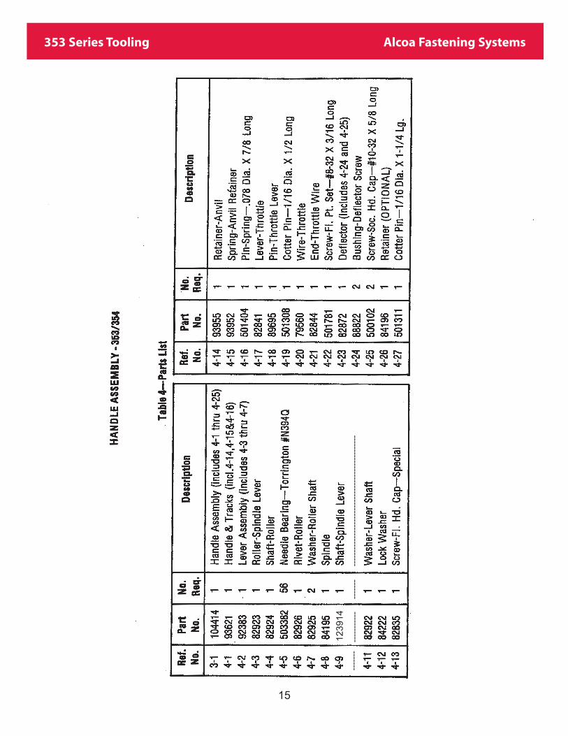
4. Parts List—Handle Assembly ........................................15
5. Parts List—Adapter Assembly ........................................17
6. Parts List—Cylinder Assembly........................................21
7. Parts List—Special Tools ................................................26
8. Parts List—Standard Tools ..........................................26
9. Parts List—Spare Parts Kit ............................................27
10. Parts List—353-51 Installation Tool Kit ..........................28
11. Parts List—353-52 Installation Tool Kit ..........................28
12. Parts List—353-53 Installation Tool Kit ..........................29
13. Parts List—353-54 Installation Tool Kit ..........................29
TABLES
1
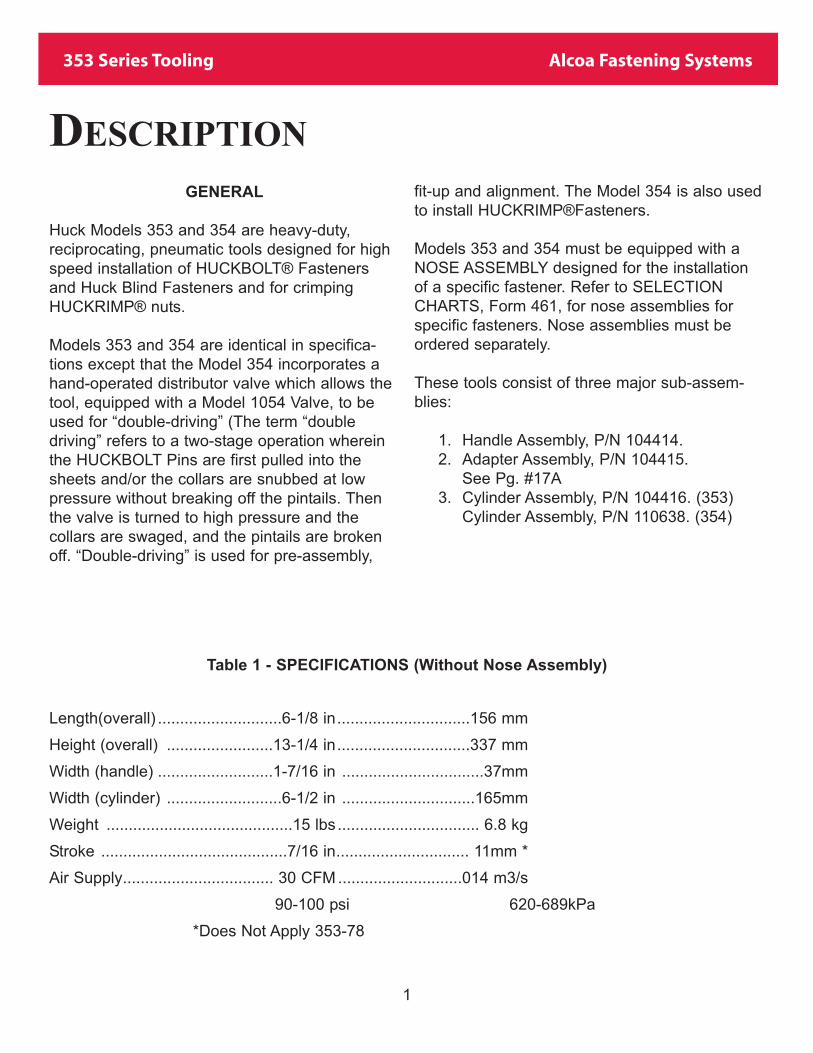
353 Series Tooling Alcoa Fastening Systems
GENERAL
Huck Models 353 and 354 are heavy-duty,
reciprocating, pneumatic tools designed for high
speed installation of HUCKBOLT® Fasteners
and Huck Blind Fasteners and for crimping
HUCKRIMP® nuts.
Models 353 and 354 are identical in specifica-
tions except that the Model 354 incorporates a
hand-operated distributor valve which allows the
tool, equipped with a Model 1054 Valve, to be
used for “double-driving” (The term “double
driving” refers to a two-stage operation wherein
the HUCKBOLT Pins are first pulled into the
sheets and/or the collars are snubbed at low
pressure without breaking off the pintails. Then
the valve is turned to high pressure and the
collars are swaged, and the pintails are broken
off. “Double-driving” is used for pre-assembly,
fit-up and alignment. The Model 354 is also used
to install HUCKRIMP®Fasteners.
Models 353 and 354 must be equipped with a
NOSE ASSEMBLY designed for the installation
of a specific fastener. Refer to SELECTION
CHARTS, Form 461, for nose assemblies for
specific fasteners. Nose assemblies must be
ordered separately.
These tools consist of three major sub-assem-
blies:
1. Handle Assembly, P/N 104414.
2. Adapter Assembly, P/N 104415.
See Pg. #17A
3. Cylinder Assembly, P/N 104416. (353)
Cylinder Assembly, P/N 110638. (354)
Table 1 - SPECIFICATIONS (Without Nose Assembly)
Length(overall) ............................6-1/8 in..............................156 mm
Height (overall) ........................13-1/4 in..............................337 mm
Width (handle) ..........................1-7/16 in ................................37mm
Width (cylinder) ..........................6-1/2 in ..............................165mm
Weight ..........................................15 lbs ................................ 6.8 kg
Stroke ..........................................7/16 in.............................. 11mm *
Air Supply.................................. 30 CFM ............................014 m3/s
90-100 psi 620-689kPa
*Does Not Apply 353-78
DESCRIPTION

2
353 Series Tooling Alcoa Fastening Systems
Refer to Figure 1
When the tool is connected to a sourceof compressed air, air flows into thecentral chamber C, around the distributorvalve and thru connecting partsinto chamber B. Pressure is also con-stantly maintained in the control valvechamber thru a connecting port. Asshown in Figure 1, all parts are shownin their normal positions, and all valvesare closed except the rear trip valvewhich is opened by the piston at the endof its return stroke.
When the control valve is opened bydepressing the throttle valve to startthe cycle, compressed air flows thru aport into the rear trip valve chamberand then into chamber D. The distributorvalve shifts directing the flow ofair to the piston causing it to driveupward. At this time air is flowing thru a
port into the front trip valve chamber. Asthe piston moves upward, the reartrip valve closes, and pressure is main-tained in chamber D and in the fronttrip valve chamber.
As the piston completes its stroke, it con-tacts and opens the front trip valve. Thisinstantly exhausts pressure from cham-ber D permitting the distributing valve tomove to its normal position. Compressedair is now directed to chamber B causingthe piston to return to its rest position.
As long as the control valve is held open(throttle valve depressed) the installationcycle is repeated until the fastener isinstalled and the operator releases thethrottle valve.
Motion is transmitted from the piston tothe spindle thru the piston rod, wedgeand lever.
PRINCIPLE OF OPERATION

3
353 Series Tooling Alcoa Fastening Systems
Fig. 1
Sectional View

4
353 Series Tooling Alcoa Fastening Systems
Fig. 2
Clearence Dimensions

5
353 Series Tooling Alcoa Fastening Systems
Models 353 and 354 Huck Installation Tools areshipped with a plastic plug in the Air InletBushing (6-14). The air inlet bushing has 1/4-18female pipe threads to accept hose fittings.Quick disconnect fittings and 3/8 inside diameterhose are recommended. (Air hose and quick dis-connect fittings are not available from Huck.) Anair supply of 90-100 psi capable of 30 CFM mustbe available. An air filter-regulator-lubricator isrecommended.
1. Remove plastic plug from Air Inlet Bushing(6-14) and pour in a small quantity of clean, light oil (SAE #10).
2. Screw Spindle Stop Nut, P/N 84213, ontospindle of tool leaving approximately 7/16 gap between head of stop nut and tool. (The tool will not reciprocate if the stop nut is turned on too far.) A stop nut is furnished witheach tool.
3. Connect tool to air supply and depressThrottle Lever (4-17). Observe action of tool the spindle should reciprocate as long as the throttle lever is depressed.
4. Select nose assembly for the fasteners to beinstalled. See SELECTION CHARTS, Form 461, in HUCK INSTALLATION EQUIPMENT DATA or available separately from your Huck representative.
5. Disconnect air supply, remove stop nut andinstall nose assembly following instructions on the NOSE ASSEMBLY DATA SHEET fur -nished with each nose assembly.
6. Connect to air supply and install a few fas-teners in a test plate of the proper thickness and having the proper size holes.
NOTE
Throughout this manual, the reference num-ber for finding a component or (sub) assem-bly is linked to the Figure Number and TableNumber where it will be found. Example: (4-8)indicates Spindle, part number 84195, foundin Figure 4 and Table 4.
PREPARATION FOR USE

6
353 Series Tooling Alcoa Fastening Systems
Reasonable care of installation tools byoperators is an important factor in main-taining tool efficiency and in reducingdown-time. Do not abuse the tool bydropping it, using it as a hammer orotherwise causing unnecessary wear andtear.
HUCKBOLT® Fastener Installation:
1. Check work and remove excessive gap. (Gap is space between sheets. Gap is excessive if not enough pintail sticks through the collar for the nose assembly to grab onto.)
2. Put HUCKBOLT Pin into hole.
3. Slide HUCKBOLT Collar over pin. (If collarhas only one tapered end, that end should be out towards the tool.)
4. Push nose assembly onto the pin until thenose assembly anvil stops against the collar. Tool and nose assembly must be held at rightangles (90°) to the work.
5. Depress Throttle Lever (4-17) and hold itdepressed.
6. When forward motion of nose assembly anvil stops and pintail breaks off, release throttle lever. Tool and nose assembly will eject off installed fastener. If “double-driving”, release throttle lever and depress hand-operated Shift Valve Button (8-2). (A self-releasing nose assembly is required for “double-driving.)
7. The tool and nose assembly is now ready forthe next installation cycle.
HUCKRIMP® Fastener Installation with 354H.I.T. (Do Not use Model 1054 Valve as used in“double-driving”)
1. Assemble KRIMPINS® and KRIMPNUTS®to structure.
2. Tighten KRIMPNUTS to specified torque.
3. Place applicable nose assembly over KRIMPNUT.
4. Depress Throttle Lever (4-17) and release.Tool and nose assembly will automatically crimp the KRIMPNUT.
5. Push Shift Valve Button (8-2) to release noseassembly from crimped KRIMPNUT.
HUCK Blind Fastener Installation:
1. The fastener maybe placed in work hole or inend of nose assembly. In either case, the tooland nose assembly must be held against the work and at right angles to it. Do not depress throttle valve until the fastener is in the hole.
2. Depress Throttle Lever (4-17) and hold itdepressed until the fastener is installed and asound denoting the pintail breaking off is heard. Release throttle lever.
WARNING
DO NOT PULL ON A PIN WITHOUT ACOLLAR EXCEPT WHEN “DOUBLEDRIVING” WITH THE PRESSURETURNED DOWN. INJURY TO WORK-ERS COULD RESULT WHEN THE PIN-TAILBREAKS BECAUSE THE PIN WILLEJECT FORCIBLY FROM THE OTHERSIDE OF THE WORK.
OPERATING INSTRUCTIONS
�

7
353 Series Tooling Alcoa Fastening Systems
GOOD SERVICE PRACTICES
The efficiency and life of a tool depends uponproper maintenance and good service practices.
Tools should be serviced by personnel who arethoroughly familiar with them and how theyoperate. If possible, the Model 353 Tool shouldbe serviced by personnel specifically trained byHuck’s training department. (See notice insideback cover.)
Disassemble only the components necessary toreplace a worn or damaged component.
During disassembly and assembly, take thefollowing precautions to avoid damaging tool orcomponents:
1. Always work in a well-lighted area and on aclean surface.
2. Use relatively soft materials, such as brass,aluminum or wood, to protect tool when applying pressure.
3. Apply a continuous strong pressure, ratherthan sharp blows, to disassemble or assemble a component. An arbor press provides steady pressure to press a component in or out.
4. Use a vise with soft jaws.
5. Never continue to force a component if it“hangs-up” due to misalignment. Reverse theprocedure to correct misalignment and startover.
6. Smear Lubriplate 130AA, or equivalent, onO-rings and mating surfaces to aid assembly and prevent damage to O-rings. (Lubriplate ismanufactured by Fiske Brothers Refining Co.and is available in most localities. A handy tube of’ Lubriplate 130AA is available from Huck as part number 502723).
7. Handle parts carefully and examine fordamage or wear. Examine O-rings for nicks or wear. A good practice is to replace all O-rings when the tool or subassembly is disassembled.
8. Follow disassembly and assembly procedures outlined in this manual.
SPARE PARTS
Perishable components are available separatelyor in Kit 102033, Table 9, and should be avail-able at all times. Other components, as experi-ence indicates, also should be available.
SERVICE TOOLS
Standard hand tools such as wrenches, drifts,copper or lead hammers, screwdrivers, socketscrew hexagon keys, etc. are required. An arborpress and vise with soft jaws should be avail-able. Standard hand tools available from Huckare shown in Table 8. Special tools are shown inFigure 7 and Table 7.
MAINTENANCE

8
353 Series Tooling Alcoa Fastening Systems
MAINTENANCE (CONT.)
PREVENTIVE MAINTENANCE
Model 353 and 354 Huck Installation Tools areproduction tools requiring a minimum amount ofmaintenance. Adherence to preventive main-tenance will help insure operating efficiency andlonger life, and eliminate down-time.
A. Air Supply
1. Keep air pressure regulated to 90-100 psi.
2. Keep moisture traps and filters clean.3. Keep lubricator filled and adjusted.4. Check air hose for deterioration or dam
age.5. Use 3/8 inside diameter air hose.
B. Installation Tool
1. Never operate tool without a nose assembly or stop nut installed on spindle.(This keeps spindle in alignment and prevents jamming.)
2. Keep screws and nuts properly tightened.3. Keep tool lubricated (See LUBRICA
TION.)4. Replace O-rings at regular intervals.
C. Nose Assembly
1. Clean nose assembly daily. Dip in mineralspirits, or other suitable solvent and depress throttle valve for a few seconds. This will wash away dirt, metal chips, etc.
2. Occasionally, as conditions indicate, dis-assemble the nose assembly and thoroughly clean. Use a sharp pick to removeimbedded particles from the grooves of the jaws. Reassemble nose assembly perapplicable Nose Assembly Data Sheet.
3. Do not use nose assembly as a pry orhammer.
LUBRICATION
Daily, before putting tool into use, remove airhose and pour a small quantity of clean, light oil(SAE #10) into the air inlet bushing. Put a fewdrops of the same light oil in Oil Holes “Y” tolubricate the spindle of the tool. Caution: Do notover-lubricate. (If too much oil is used, theexcess may find its way to the nose assemblyjaws. The oil causes dirt to collect in thegrooves of the jaws and causes the jaws to slipover the grooves of the pin.) See Figure 2 forlocation of Oil Holes Y.
9
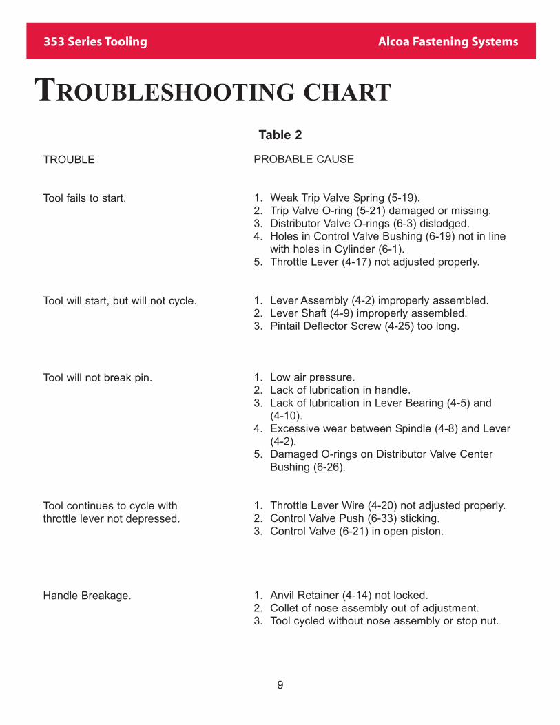
353 Series Tooling Alcoa Fastening Systems
TROUBLE
Tool fails to start.
Tool will start, but will not cycle.
Tool will not break pin.
Tool continues to cycle withthrottle lever not depressed.
Handle Breakage.
TROUBLESHOOTING CHART
Table 2
PROBABLE CAUSE
1. Weak Trip Valve Spring (5-19).2. Trip Valve O-ring (5-21) damaged or missing.3. Distributor Valve O-rings (6-3) dislodged.4. Holes in Control Valve Bushing (6-19) not in line
with holes in Cylinder (6-1).5. Throttle Lever (4-17) not adjusted properly.
1. Lever Assembly (4-2) improperly assembled.2. Lever Shaft (4-9) improperly assembled.3. Pintail Deflector Screw (4-25) too long.
1. Low air pressure.2. Lack of lubrication in handle.3. Lack of lubrication in Lever Bearing (4-5) and
(4-10).4. Excessive wear between Spindle (4-8) and Lever
(4-2).5. Damaged O-rings on Distributor Valve Center
Bushing (6-26).
1. Throttle Lever Wire (4-20) not adjusted properly.2. Control Valve Push (6-33) sticking.3. Control Valve (6-21) in open piston.
1. Anvil Retainer (4-14) not locked.2. Collet of nose assembly out of adjustment.3. Tool cycled without nose assembly or stop nut.

10
353 Series Tooling Alcoa Fastening Systems
Fig. 3
Major Sub-assemblies
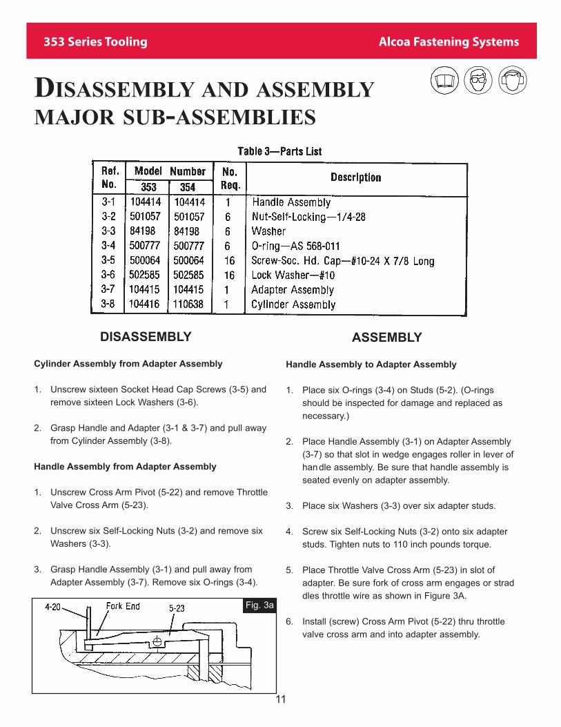
11
353 Series Tooling Alcoa Fastening Systems
DISASSEMBLY
Cylinder Assembly from Adapter Assembly
1. Unscrew sixteen Socket Head Cap Screws (3-5) and
remove sixteen Lock Washers (3-6).
2. Grasp Handle and Adapter (3-1 & 3-7) and pull away
from Cylinder Assembly (3-8).
Handle Assembly from Adapter Assembly
1. Unscrew Cross Arm Pivot (5-22) and remove Throttle
Valve Cross Arm (5-23).
2. Unscrew six Self-Locking Nuts (3-2) and remove six
Washers (3-3).
3. Grasp Handle Assembly (3-1) and pull away from
Adapter Assembly (3-7). Remove six O-rings (3-4).
ASSEMBLY
Handle Assembly to Adapter Assembly
1. Place six O-rings (3-4) on Studs (5-2). (O-rings
should be inspected for damage and replaced as
necessary.)
2. Place Handle Assembly (3-1) on Adapter Assembly
(3-7) so that slot in wedge engages roller in lever of
handle assembly. Be sure that handle assembly is
seated evenly on adapter assembly.
3. Place six Washers (3-3) over six adapter studs.
4. Screw six Self-Locking Nuts (3-2) onto six adapter
studs. Tighten nuts to 110 inch pounds torque.
5. Place Throttle Valve Cross Arm (5-23) in slot of
adapter. Be sure fork of cross arm engages or strad
dles throttle wire as shown in Figure 3A.
6. Install (screw) Cross Arm Pivot (5-22) thru throttle
valve cross arm and into adapter assembly.
Fig. 3a
DISASSEMBLY AND ASSEMBLY
MAJOR SUB-ASSEMBLIES

12
353 Series Tooling Alcoa Fastening Systems
Cylinder Assembly to Adapter Assembly
1. Smear Lubriplate on piston O-ring (5-14). (O-ring
should be inspected for damage and re- placed as
necessary.)
2. Place Gasket (5-11) between adapter and cylinder.
3. Carefully push piston of Adapter Assembly (3-7) into
Cylinder Assembly (3-8).
4. Push two assemblies together. Be sure adapter seats
evenly on top of the cylinder.
5. Install sixteen Socket Head Cap Screws (3-5) with six
teen Lock Washers (3-6) to secure Adapter Assembly
to Cylinder Assembly. Tighten screws to 50 inch
pounds torque.
After the tool Is completely reassembled, the Throttle
Lever (4-17) can be adjusted to suit by repositioning
Throttle Wire Adjusting End (4-21).
6. Remove Spindle (4-8).
7. Drive anvil retainer Spring Pin (4-16) out of handle,
and remove Anvil Retainer (4-14) and Spring (4-15).
8. Unscrew Flat Point Set Screw (4-22), and remove
Throttle Wire (4-20) and Throttle Wire End (4-21).
9. Remove Cotter Pin (4-19) and remove Throttle Lover
Pin (4-18) and Throttle Lever (4-17).
HANDLE ASSEMBLY
DISASSEMBLY
1. Unscrew two Socket Read Cap Screws (4-25) and
remove Deflector (4-23) and Bushings (4-24).
2. Unscrew Flat Head Cap Screw (4-13) and remove
Washer (4-11) and Lock Washer (4-12).
.
3. Push Spindle Lever Shaft (4-9) with Needle Bearings
(4-10) out of Handle and Tracks Assembly (4-1).
4. Remove Lever Assembly (4-2) from handle
5. If necessary to replace Spindle Lever Roller (4-3),
Needle Bearings (4-5) or Roller Shaft (4-4), drill out
Rivet (4-6) head as shown in Figure 4A. Press rivet
out and remove Washers (4-7), shaft, bearings and
roller.
ASSEMBLY
1. Position Throttle Lever (4-17) in Handle (4-1) and push
Throttle Lever Pin (4-18) thru handle and lever. Install
Cotter Pin (4-19).
2. Place Throttle Wire (4-20) into handle and install
Throttle Wire End (4-21) and Flat Point Set Screw
(4-22).
3. Insert Anvil Retainer Spring (4-15) in noseend of han
dle. Insert Anvil Retainer (4-14) and depress while
driving Spring Pin (4-16) into cross holes.
4. Drop Spindle (4-8) into position in Handle (4-1).
5. Reassemble Lever Assembly (4-2). Place Spindle
Lever Roller (4-3) in position in lever and press Roller
Shaft (4-4) thin roller as shown in Figure 4B. Insert
twenty-eight Needle Bearings (4-5) on both ends of
Roller Shaft (4-4).
DISASSEMBLY AND ASSEMBLY
HANDLE ASSEMBLY
Fig. 4a

13
353 Series Tooling Alcoa Fastening Systems
10. Place Lock Washer (4-12) on Flat Head Cap Screw (4-
13) and screw into Spindle Lever Shaft (4-9). Stake
sides of Lockwasher (4-12) into detents in Flat Head
Cap Screw (4-13) and Lever Shaft Washer (4-11),
11. Insert Deflector Screw Bushings (4-24) in Deflector
(4-23).
12. Place Deflector (4-23) on Handle Assembly (4-1) and
insert Socket Head Cap Screw (4-25) thru Bushings
(4-24) and screw into handle.
13. Retainer (4-26) and Cotter Pin (4-27) are optional
components to use in place of Retainer (4-14), Spring
(4-15) and Spring Pin (4-16). These optional compo
nents are not furnished with the tool.
Fig. 4b
DISASSEMBLY AND ASSEMBLY
HANDLE ASSEMBLY (CONT.)
Fig. 4c
Place Roller shaft Washers (4-7) on both sides of lever.
Insert Roller Rivet (4-6) thru washers and shaft and peen
rivet flush with washer.
6. Insert Lever Assembly (4-2) in Handle and Tracks
Assembly (4-1).
Heavy grease Is recommended for holding bearings in
place during assembly.
7. Place forty-seven Needle Bearings (4-10) on each end
of Spindle Lever Shaft (4-9).
8. Line up hole in Lever Assembly (4-2) and Handle
Assembly (4-1) and insert Spindle Lever Shaft (4-9)
and Bearing (4-10).
Make sure lever straddles flats on spindle and milled
slot of lever faces toward Throttle Lever (4-17).
9. Place Lever Shaft Washer (4-11) in position with inte
gral keys engaging keyways “A” and as shown in
Figure 4C.
Make sure that keyway “A” in the end of the Spindle
Lever Shaft (4-9) is directly opposite to keyway “B” in
HandleAssembly (4-1) as shown in Figure 4C.
This will result in milled slot “C” lacing towards the
Throttle Lever (4-17).

14
353 Series Tooling Alcoa Fastening Systems
Fig. 4
Handle Assembly
15
353 Series Tooling Alcoa Fastening Systems
----
---
----
----
---
----
---
----
----
----
----
----
----
----
----
----
----
----
---
123914

16
353 Series Tooling Alcoa Fastening Systems
Fig. 5
Adapter Assembly

17
353 Series Tooling Alcoa Fastening Systems

17A
353 Series Tooling Alcoa Fastening Systems

18
353 Series Tooling Alcoa Fastening Systems
Fig. 5a
DISASSEMBLY AND ASSEMBLY
ADAPTER ASSEMBLY
DISASSEMBLY
1. Remove Cage and Bearing Assembly (5-8).
2. Unscrew Socket Head Cap Screw (5-15) and remove
Piston (5-13).
3. Remove O-ring (5-14) from piston.
4. Remove Casket (5-11) and Bumper (5-12).
5. Remove Wedge & Piston Rod (5-9).
6. Unscrew six Adapter Studs (5-2). (Note: Left hand
threads.)
7. If Bearing Cage Stop Pins (5-7) are damaged, return
Adapter Assembly (3-7) or (5-1) to one of the repair
facilities listed on inside of the back cover.
8. Press Adapter Seal (5-6) out of Adapter (5-1).
Remove only if necessary to replace a damaged seal.
If seal Is removed it must be replaced by a new one.
9. Remove Lower Bearing (5-10) from handle.
10. Use a scriber or other pointed object, and remove
Valve Cover Retainer (5-16).
11. Remove Front Trip Valve Cover (5-17), Bumper (5-18),
Spring (5-19), Front Trip Valve (5-20) and O-ring (5-
21).
12. Remove O-ring (5-21) from Front Trip Valve (5-20).
13. Remove Trip Valve Inner Bushing (5-5) and Trip Valve
Outer Bushing (5-3).
Valve Bushing Pin (5-4) must be driven out before
removing Outer Bushing (5-3).
ASSEMBLY
1. Place lower Bearing (5-10) in handle.
2. Press Adapter Seal (5-6) into Adapter (5-1) as shown
in Figure SA.
CAUTION
Seals are extremely delicate and care must be taken to
press them into place flush and square with bore.
3. Press Trip Valve Inner Bushing (5-5) into Adapter (5-1)
with cross-hole in line with hole in adapter as shown in
Figure 5B. Ream inside diameter to .1250-.1255.
4. Press Trip Valve Outer Bushing (5-3) into Adapter (5-1)
with slot positioned as shown, in Figure 5B. Use bole
in adapter as guide and drill 7/64 diameter and ream
.124-125 diameter hole for Valve Bushing Pin (5-4).
Drive Pin (5-4) into adapter and bushing as shown in
Figure 5B.
5. Place O-ring (5-21) on stem of Front Trip Valve (5-20).
6. Insert Front Trip Valve (5-20) into Inner Bushing (5-5).
Drop Front Trip Valve Spring (5-19) over head of front
trip valve and place Front Trip Valve Bumper (5-18)
inside of spring.

19
353 Series Tooling Alcoa Fastening Systems
7. Place Front Trip Valve Cover (5-17) into Outer Bushing
(5-3) and install Valve Cover Retainer (5-16) in internal
groove of outer bushing.
8. Screw six Adapter Studs (5-2) into Adapter (5-1) as
shown in Figure 5A. Caution: LEFT HAND THREAD.
Unless adapter studs are screwed into the adapter to
their full predetermined depth, the adapter stud nut
will bear directly on the square section of the adapter,
leaving the handle loose on the studs. Turn studs in to
match pattern of mating square holes in handle. Use
Loctite Adhesive/Sealant on the threads. Follow
instructions on Loctite package. (Loctite
Adhesive/Sealant is manufac- tured by the Loctite
Corp. and is available locally or from Huck in a 0.5 cc
tube as part number 503657.)
9. Place Cylinder Adapter Gasket (5-11) and Piston
Bumper (5-12) on Adapter (5-1).
10. Insert rod of Wedge and Piston Rod (5-9) thru Seal
(5-6).
11. Install O-ring (5-14) on Piston (5-13).
12. Position Piston (5-13) on Wedge and Piston Rod (5-9)
and screw Socket Head Cap Screw (5-15) thin piston
into rod. Tighten screw to 55 foot pounds torque.
The Wedge and Piston Rod (5-9) in earlier tools uti-
lized an integral stud and nut in place of the present
socket head cap screw. When assembling these tools,
make sure the chamfered side of piston rod hole
enters on rod first as marked.
13. Place Cage and Bearing Assembly (5-8) on Wedge
and Piston Rod (5-9).
Smear heavy grease on both bearings before assem-
bling.
Fig. 5b
DISASSEMBLY AND ASSEMBLY
ADAPTER ASSEMBLY (CONT.)

20
353 Series Tooling Alcoa Fastening Systems
Fig. 6
Cylinder Assembly

21
353 Series Tooling Alcoa Fastening Systems

22
353 Series Tooling Alcoa Fastening Systems
DISASSEMBLY
1. Remove Control Valve Push Pin (6-33).
2. Unscrew Bushing Lock Nut (6-32), and remove Lock
Ring (6-31).
3. Unscrew Distributor Valve Bushing (6-30), and remove
three O-rings (6-29), one O-ring (6-5) and Valve Piston
(6-28).
4. Unscrew Bushing Lock Nut (6-8), and remove Lock
Ring (6-7).
5. Unscrew Distributor Valve Bushing (6-6), and remove
O-ring (6-5).
6. Unscrew fours Round Screws (6-17).
7. Remove Muffler Plate (6-16) and Packing (6-15).
8. Unscrew Center Bushing Screw (6-10) and O-ring
(6-9).
9. Remove Return Valve Cylinder (6-4).
CAUTION
Always remove Center Bushing Screw (6-10) before
attempting to remove Distributor Valve (6-2).
10. Remove Distributor Valve (6-2) and remove two O-
rings (6-3A) and O-ring (6-3B).
11. Remove Distributor Valve Center Bushing (6-26) and
remove two inner O-rings (6-3C) and two outer O-
rings (6-27).
12. Unscrew Air Inlet Bushing (6-14) and remove O-ring
(6-13).
13. Remove Lock Washer (6-12) and seat (6-11).
14. Unscrew Control Valve Cap (6-24).
15. Remove Valve Spring (6-23), O-ring Cap (6-22), O-ring
(6-20) and Valve (6-21) from control valve chamber.
16. Remove Rear Trip Valve Cap (6-25).
17. Remove Valve Spring (6-23), O-ring Cap (6-22), O-ring
(6-20) and Valve (6-21) from rear trip Valve chamber.
18. Extract Rear Trip Valve Bushing (6-18) and Control
Valve Bushing (6-19)
ASSEMBLY
1. Press Rear Trip Valve Bushing (6-18) and Control
Valve Bushing (6-19) into Cylinder (6-1) as shown in
Figure 6A. Cross holes in bushings must line up with
cross holes in cylinder. Ream inside diameter of both
bushings to .1250-.1255.
Fig. 6a
DISASSEMBLY AND ASSEMBLY
CYLINDER ASSEMBLY - 353

23
353 Series Tooling Alcoa Fastening Systems
2. Place O-ring (6-20) and O-ring Cap (6-22) on Valves
(6-21), as shown in Figure 6B, and insert into
Bushings (6-18) and (6-19). Place Valve Springs (6-23)
on top of valves.
3. Screw Control Valve Cap (6-24) into Bushing (6-19).
4. Screw Rear Trip Valve Cap (6-25) into Bushing (6-18).
5. Place O-ring (6-13) on Air Inlet Bushing (6-14).
6. Place Lock Washer Seat (6-11) on cylinder.
7. Place Lock Washer (6-12) on Air Inlet Bushing (6-14)
and screw it into cylinder.
8. Install two O-rings (6-3C) in the internal grooves of
Distributor Valve Center Bushing (6-26). Install two O-
rings (6-27) in external grooves.
9. Push Distributor Valve Center Bushing (6-26) into
Cylinder, lining up tapped hole in bushing with hole in
exhaust muffler packing cavity.
CAUTION
The extension end of this bushing marked “REAR”
must face toward Distributor Valve Return Cylinder (6-
4) (Rear of tool.) If bushing is installed backwards, the
tool will operate sluggishly.
10. Install O-ring (6-9) on Center Bushing Screw (6-10).
11. Lock Distributor Valve Center Bushing (6-26) into
Cylinder with Screw (6-10) as shown in Figure 6C.
Make sure end of screw does not protrude thru
bushing into distributor valve chamber.
12. Place Exhaust Muffler Packing (6-15) into cylinder
cavity and install Muffler Plate (6-16) using four
Button Head Screws (6-17).
13. Place two O-rings (6-3A) and O-ring (6-3B) on distribu
tor Valve (6-2).
14. Place Valve Return Cylinder (6-4) on small end of
Distributor Valve (6-2).
Use GUNSLICK or equivalent when assembling distrib-
utor valve. (GUN-SLICK is manufactured by Outers
Labs. Onalaska, Wis. A small tube of GUN-SLICK is
available from Huck as part number 503661.)
DISASSEMBLY AND ASSEMBLY
CYLINDER ASSEMBLY - 353 (CONT.)
Fig. 6c
Fig. 6b
24
353 Series Tooling Alcoa Fastening Systems
15. Insert distributor valve and return cylinder into center
bushing with small end of distributor valve facing the
rear of the tool.
16. If Distributor Valve Bushing (6-30) and/or Valve Piston
(6-28) requires replacement the new bushing and pis
ton must be lapped together to provide a smooth slid
ing fit. (The small end of the piston is threaded (1/4-
28) to facilitate lapping.)
17. Install three O-rings (6-29) and O-ring (6-5) on
Distributor Valve Bushing (6-30).
18. Screw Distributor Valve Bushing (6-30) with Piston
(6-28) inside into cylinder until end of bushing touches
Distributor Valve Center Bushing (6-26).
19. Lock bushing in position with Bushing Lock Ring (6-31)
and Bushing Lock Nut (6-32).
20. Install O-ring (6-5) on Distributor Valve Bushing (6-6).
21. Screw Distributor Valve Bushing (6-6) into cylinder until
end of bushing touches Distributor Valve Center
Bushing (6-26).
22. Lock bushing in position with Bushing Lock Ring (6-7)
and Bushing Lock Nut (6-8).
23. Place Control Valve Push Pin (6-33) into Cylinder (1).
CYLINDER ASSEMBLY—354
Cylinder Assembly, Ref. No. 3-8, P/N 110638, for the
Model 354 Huck Installation Tool is the same as Ref. No.
3-8, P/N 104416, for the Model 353 Huck Installation Tool
except:
1. Ref. No. 6-4, P/N 89310, Valve Return Cylinder, is not
used.
2. P/N 102490, Shift Cylinder replaces P/N 89310,
Cylinder.
3. P/N 102491, Shift Valve Button is screwed onto 102490,
Cylinder.
The Model 354 may be purchased complete or a Model
353 may be converted in a few minutes. See Figure 8 and
CONVERSION—MODEL 353 TO 354.
DISASSEMBLY AND ASSEMBLY
CYLINDER ASSEMBLY - 354
DISASSEMBLY AND ASSEMBLY
CYLINDER ASSEMBLY - 353 (CONT.)

25
353 Series Tooling Alcoa Fastening Systems
Fig. 7
Special Tools

26
353 Series Tooling Alcoa Fastening Systems

353 Series Tooling Alcoa Fastening Systems
27
353 Series Tooling Alcoa Fastening Systems
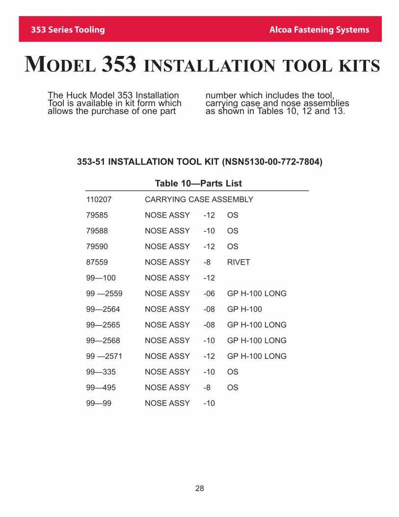
Table 10—Parts List
110207 CARRYING CASE ASSEMBLY
79585 NOSE ASSY -12 OS
79588 NOSE ASSY -10 OS
79590 NOSE ASSY -12 OS
87559 NOSE ASSY -8 RIVET
99—100 NOSE ASSY -12
99 —2559 NOSE ASSY -06 GP H-100 LONG
99—2564 NOSE ASSY -08 GP H-100
99—2565 NOSE ASSY -08 GP H-100 LONG
99—2568 NOSE ASSY -10 GP H-100 LONG
99 —2571 NOSE ASSY -12 GP H-100 LONG
99—335 NOSE ASSY -10 OS
99—495 NOSE ASSY -8 OS
99—99 NOSE ASSY -10
28
MODEL 353 INSTALLATION TOOL KITS
353-51 INSTALLATION TOOL KIT (NSN5130-00-772-7804)
The Huck Model 353 InstallationTool is available in kit form whichallows the purchase of one part
number which includes the tool,carrying case and nose assembliesas shown in Tables 10, 12 and 13.
353 Series Tooling Alcoa Fastening Systems
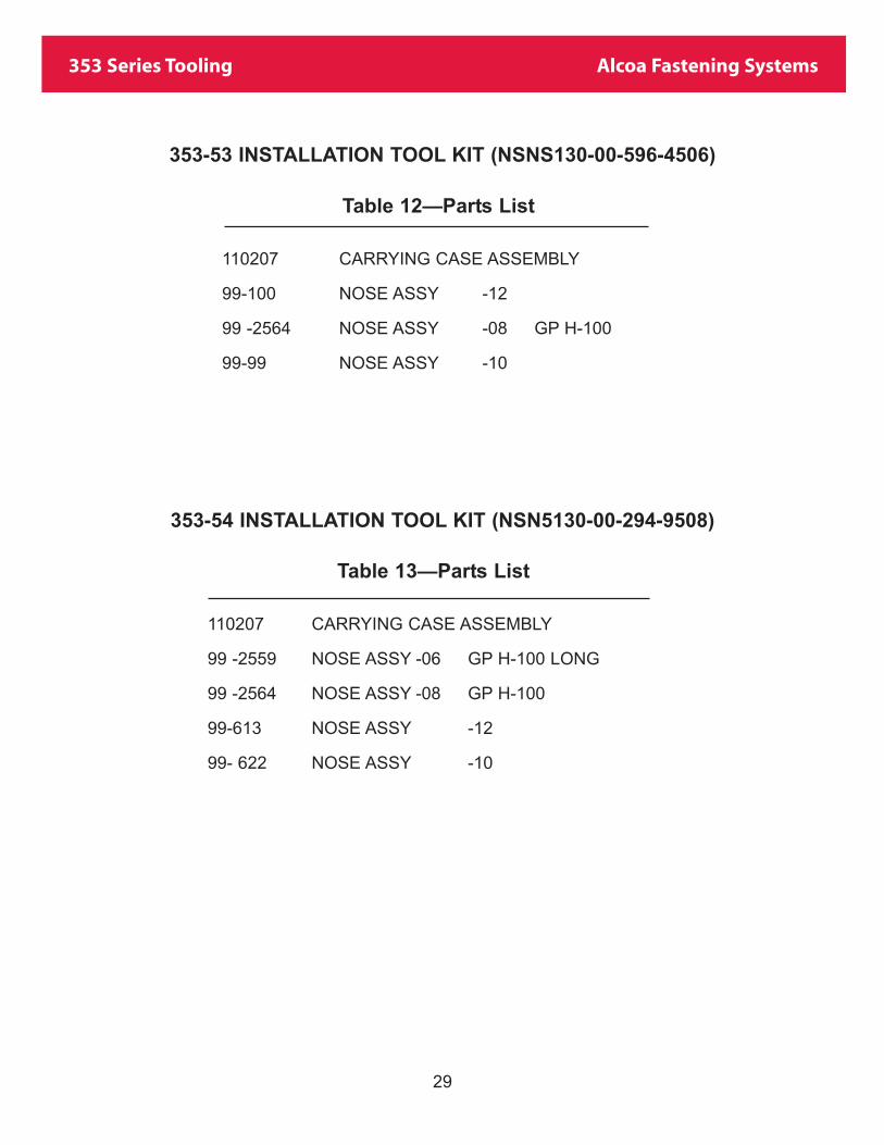
353-53 INSTALLATION TOOL KIT (NSNS130-00-596-4506)
Table 12—Parts List
110207 CARRYING CASE ASSEMBLY
99-100 NOSE ASSY -12
99 -2564 NOSE ASSY -08 GP H-100
99-99 NOSE ASSY -10
353-54 INSTALLATION TOOL KIT (NSN5130-00-294-9508)
Table 13—Parts List
110207 CARRYING CASE ASSEMBLY
99 -2559 NOSE ASSY -06 GP H-100 LONG
99 -2564 NOSE ASSY -08 GP H-100
99-613 NOSE ASSY -12
99- 622 NOSE ASSY -10
29

353 Series Tooling Alcoa Fastening Systems
DISASSEMBLY
1. Remove 84449, Lock Nut, and 84448, Lock Ring.
2. Remove 84447, Bushing, and 89310, Valve Return Cylinder (Ref. No. 6-4).
ASSEMBLY
1. Smear Lubriplate 130AA inside of 102490,Shift Cylinder and push into tool until itengages 89308, Distributor Valve.
2. Smear Lubriplate 130AA on C-ring on84447, Bushing. Screw Bushing into tool untilit bottoms out on 89306, Valve Center Bushing.
3. Install 84448 Lock Ring and 84449 Lock Nut. Do not over-tighten Lock Nut - just snug-up.
4. Screw 102491, Button, onto shaft of 102490,Shift Cylinder.
30
Fig. 8
Partial Bottom View
353 Series Tooling Alcoa Fastening Systems
LIMITED WARRANTIESTooling Warranty: Huck warrants that tooling and other
items (excluding fasteners, and hereinafter referred as
"other items") manufactured by Huck shall be free from
defects in workmanship and materials for a period of nine-
ty (90) days from the date of original purchase.
Warranty on "non standard or custom manufactured
products": With regard to non-standard products or cus-
tom manufactured products to customer's specifications,
Huck warrants for a period of ninety (90) days from the
date of purchase that such products shall meet Buyer's
specifications, be free of defects in workmanship and
materials. Such warranty shall not be effective with
respect to non-standard or custom products manufactured
using buyer-supplied molds, material, tooling and fixtures
that are not in good condition or repair and suitable for
their intended purpose.
THERE ARE NO WARRANTIES WHICH EXTEND
BEYOND THE DESCRIPTION ON THE FACE HEREOF.
HUCK MAKES NO OTHER WARRANTIES AND
EXPRESSLY DISCLAIMS ANY OTHER WARRANTIES,
INCLUDING IMPLIED WARRANTIES AS TO MER-
CHANTABILITY OR AS TO THE FITNESS OF THE
TOOLING, OTHER ITEMS, NONSTANDARD OR CUS-
TOM MANUFACTURED PRODUCTS FOR ANY PARTIC-
ULAR PURPOSE AND HUCK SHALL NOT BE LIABLE
FOR ANY LOSS OR DAMAGE, DIRECTLY OR INDI-
RECTLY, ARISING FROM THE USE OF SUCH TOOL-
ING, OTHER ITEMS, NONSTANDARD OR CUSTOM
MANUFACTURED PRODUCTS OR BREACH OF WAR-
RANTY OR FOR ANY CLAIM FOR INCIDENTAL OR
CONSEQUENTIAL DAMAGES.
Huck's sole liability and Buyer's exclusive remedy for any
breach of warranty shall be limited, at Huck's option, to
replacement or repair, at FOB Huck's plant, of Huck man-
ufactured tooling, other items, nonstandard or custom
products found to be defective in specifications, workman-
ship and materials not otherwise the direct or indirect
cause of Buyer supplied molds, material, tooling or fix-
tures. Buyer shall give Huck written notice of claims for
defects within the ninety (90) day warranty period for tool-
ing, other items, nonstandard or custom products
described above and Huck shall inspect products for which
such claim is made.
Tooling, Part(s) and Other Items not manufactured by
Huck.
HUCK MAKES NO WARRANTY WITH RESPECT TO
THE TOOLING, PART(S) OR OTHER ITEMS MANUFAC-
TURED BY THIRD PARTIES. HUCK EXPRESSLY DIS-
CLAIMS ANY WARRANTY EXPRESSED OR IMPLIED,
AS TO THE CONDITION, DESIGN, OPERATION, MER-
CHANTABILITY OR FITNESS FOR USE OF ANY TOOL,
PART(S), OR OTHER ITEMS THEREOF NOT MANU-
FACTURED BY HUCK. HUCK SHALL NOT BE LIABLE
FOR ANY LOSS OR DAMAGE, DIRECTLY OR INDI-
RECTLY, ARISING FROM THE USE OF SUCH TOOL-
ING, PART(S) OR OTHER ITEMS OR BREACH OF
WARRANTY OR FOR ANY CLAIM FOR INCIDENTAL
OR CONSEQUENTIAL DAMAGES.
The only warranties made with respect to such tool, part(s)
or other items thereof are those made by the manufactur-
er thereof and Huck agrees to cooperate with Buyer in
enforcing such warranties when such action is necessary.
Huck shall not be liable for any loss or damage resulting
from delays or nonfulfillment of orders owing to strikes,
fires, accidents, transportation companies or for any rea-
son or reasons beyond the control of the Huck or its sup-
pliers.
Huck Installation Equipment
Huck International, Inc. reserves the right to make
changes in specifications and design and to discontinue
models without notice.
Huck Installation Equipment should be serviced by trained
service technicians only.
Always give the Serial Number of the equipment when cor-
responding or ordering service parts.
Complete repair facilities are maintained by Huck
International, Inc. Please contact one of the offices listed
below.
Eastern
One Corporate Drive Kingston, New York 12401-0250
Telephone (845) 331-7300 FAX (845) 334-7333
Canada
6150 Kennedy Road Unit 10, Mississauga, Ontario,
L5T2J4, Canada.
Telephone (905) 564-4825 FAX (905) 564-1963
Outside USA and Canada
Contact your nearest Huck International Office, see back
cover.
In addition to the above repair facilities, there are
Authorized Tool Service Centers (ATSC's) located
throughout the United States. These service centers offer
repair services, spare parts, Service Parts Kits, Service
Tools Kits and Nose Assemblies. Please contact your
Huck Representative or the nearest Huck office listed on
the back cover for the ATSC in your area.

Americas
Alcoa Fastening SystemsAerospace ProductsTucson Operations3724 East ColumbiaTucson, AZ 85714800-234-4825520-747-9898FAX: 520-748-2142
Alcoa Fastening SystemsAerospace ProductsCarson OperationsPO Box 5268900 Watson Center Rd.Carson, CA 90749800-421-1459310-830-8200FAX: 310-830-1436
Alcoa Fastening SystemsCommercial ProductsWaco OperationsPO Box 81178001 Imperial DriveWaco, TX 76714-8117800-388-4825254-776-2000FAX: 254-751-5259
Alcoa Fastening SystemsCommercial ProductsKingston Operations1 Corporate DriveKingston, NY 12401800-431-3091845-331-7300FAX: 845-334-7333www.hucktools.com
Alcoa Fastening SystemsCommercial ProductsCanada Operations6150 Kennedy Road, Unit 10Mississagua, Ontario L5T2J4Canada905-564-4825FAX: 905-564-1963
Alcoa Fastening SystemsCommercial ProductsLatin America OperationsAvenida Parque Lira. 79-402Tacubaya Mexico, D.F.C.P. 11850FAX: 525-515-1776TELEX: 1173530 LUKSME
Far East
Alcoa Fastening SystemsCommercial ProductsAustralia Operations14 Viewtech PlaceRowville, Victoria Australia 317803-764-5500Toll Free: 008-335-030FAX: 03-764-5510
Europe
Alcoa Fastening SystemsCommercial ProductsUnited Kingdom OperationsUnit C, Stafford Park 7Telford, ShropshireEngland TF3 3BQ01952-290011FAX: 0952-290459
Alcoa Fastening SystemsAerospace ProductsFrance OperationsClos D’AssevilleBP495450 Us Par VignyFrance33-1-30-27-9500FAX: 33-1-34-66-0600
For the Long Haul™
A Global OrganizationAlcoa Fastening Systems (AFS) maintains companyoffices throughout the United States and Canada,with subsidiary offices in many other countries.Authorized AFS distributors are also located inmany of the world’s
industrial and Aerspace centers, where they providea ready source of AFS fasteners, installation tools,tool parts, and application assistance.
For The Long Haul, The Future of Fastening Technology, The Future of Assembly Technology, The Future of ToolingTechnology, and Tools of Productivity are service marks of HuckInternational. Huck provides technical assistance regarding the useand application of Huck fasteners and tooling.
NOTICE: The information contained in this publication is only forgeneral guidance with regard to properties of the products shown
and/or the means for selecting such products, and is not intendedto create any warranty, express, implied, or statutory; all warrantiesare contained only in Huck’s written quotations, acknowledge-ments, and/or purchase orders. It is recommended that the usersecure specific, up-to-date data and information regarding eachapplication and/or use of such products.
HWB898 1003-5M
© 2003 Alcoa Fastening Systems
1 Corporate Drive, Kingston, NY 12401 • Tel: 800-431-3091 • Fax: 845-334-7333 • E-mail: [email protected] • www.alcoafasteningsystems.com
Alcoa Fastening Systems world-wide locations:
One Great ConnectionSM