Embed Size (px)
Citation preview

Instruction Manual
Model 3000 Load Cell
No part of this instruction manual may be reproduced, by any means, without the written consent of Geokon, Inc.
The information contained herein is believed to be accurate and reliable. However, Geokon, Inc. assumes no responsibility for errors, omissions, or misinterpretation. The information herein is subject to change without notification.
Copyright © 1981-2017 by Geokon, Inc.
(REV L, 12/14/2017)


Warranty Statement Geokon, Inc. warrants its products to be free of defects in materials and workmanship, under normal use and service for a period of 13 months from date of purchase. If the unit should malfunction, it must be returned to the factory for evaluation, freight prepaid. Upon examination by Geokon, if the unit is found to be defective, it will be repaired or replaced at no charge. However, the WARRANTY is VOID if the unit shows evidence of having been tampered with or shows evidence of being damaged as a result of excessive corrosion or current, heat, moisture or vibration, improper specification, misapplication, misuse or other operating conditions outside of Geokon's control. Components which wear or which are damaged by misuse are not warranted. This includes fuses and batteries. Geokon manufactures scientific instruments whose misuse is potentially dangerous. The instruments are intended to be installed and used only by qualified personnel. There are no warranties except as stated herein. There are no other warranties, expressed or implied, including but not limited to the implied warranties of merchantability and of fitness for a particular purpose. Geokon, Inc. is not responsible for any damages or losses caused to other equipment, whether direct, indirect, incidental, special or consequential which the purchaser may experience as a result of the installation or use of the product. The buyer's sole remedy for any breach of this agreement by Geokon, Inc. or any breach of any warranty by Geokon, Inc. shall not exceed the purchase price paid by the purchaser to Geokon, Inc. for the unit or units, or equipment directly affected by such breach. Under no circumstances will Geokon reimburse the claimant for loss incurred in removing and/or reinstalling equipment. Every precaution for accuracy has been taken in the preparation of manuals and/or software, however, Geokon, Inc. neither assumes responsibility for any omissions or errors that may appear nor assumes liability for any damages or losses that result from the use of the products in accordance with the information contained in the manual or software.


TABLE of CONTENTS
1. THEORY OF OPERATION .................................................................................................................................. 1 1.1 THEORY OF OPERATION ....................................................................................................................................... 1 1.2 LOAD CELL DESIGN AND CONSTRUCTION ........................................................................................................... 2
1.2.1 Friction Between the Bearing Plate and Load Cell .................................................................................... 4 1.2.2 Warping of the Bearing Plates and Bearing Plate Design.......................................................................... 4 1.2.3 Eccentric Loading ....................................................................................................................................... 5 1.2.4 Elastic Behavior .......................................................................................................................................... 5 1.2.5 Temperature Effects .................................................................................................................................... 5
2. INSTALLATION .................................................................................................................................................... 6 2.1 PRELIMINARY TESTS............................................................................................................................................ 6 2.2 LOAD CELL INSTALLATION .................................................................................................................................. 6
2.2.1 Transportation ............................................................................................................................................ 6 2.2.2 Initial No-Load Reading ............................................................................................................................. 6 2.2.3 Installation on Tie-Backs and Rockbolts ..................................................................................................... 6
2.3 CABLE INSTALLATION AND SPLICING .................................................................................................................. 7 2.4 ELECTRICAL NOISE .............................................................................................................................................. 7 2.5 ENVIRONMENTAL FACTORS ................................................................................................................................. 7 2.6 LIGHTNING PROTECTION ..................................................................................................................................... 8
3. TAKING READINGS ............................................................................................................................................. 9 3.1 GK-502 READOUT BOX ....................................................................................................................................... 9
3.1.1 Operating the GK-502 ................................................................................................................................ 9 3.2 VISHAY MICRO-MEASUREMENTS P3 READOUT BOX ........................................................................................ 10
3.2.1 Single Load Cell Load - Output in Engineering Units .............................................................................. 10 3.2.2 Multiple load cells ..................................................................................................................................... 11
4. DATA REDUCTION ............................................................................................................................................ 12 4.1 LOAD CALCULATION WHEN READING DIGITS ON THE GK-502......................................................................... 12 4.2 LOAD CALCULATION WHEN READING THE OUTPUT IN MV/V ON A MODEL P3 READOUT BOX. ......................... 13
5. TROUBLESHOOTING ........................................................................................................................................ 14 5.1 READOUTS ......................................................................................................................................................... 14 5.2 LOAD CELLS ...................................................................................................................................................... 14
APPENDIX A. SPECIFICATIONS ......................................................................................................................... 15
APPENDIX B. WIRING AND CONNECTOR PINOUTS .................................................................................... 16 B.1 WIRING DIAGRAM WITH P3 READOUT .............................................................................................................. 16 B.2 WIRING DIAGRAM WITH REMOTE SENSE (GK-502 READOUT) ......................................................................... 16 B.3 WIRING FOR USE WITH GK 502 READOUT BOX ................................................................................................ 17 B.4 P3 CONNECTION ............................................................................................................................................... 17
APPENDIX C. SAMPLE CALIBRATION SHEET .............................................................................................. 18
APPENDIX D. LOAD CELL CALIBRATIONS - EFFECTS OF BEARING PLATE WARPING.................. 19 D.1 INTRODUCTION ................................................................................................................................................. 19 D.2 LOAD CELL CALIBRATION PROCEDURES .......................................................................................................... 19 D.3 FIELD ARRANGEMENT ...................................................................................................................................... 19 D.4 EFFECTS OF JACK SIZE ON LOAD CELL READING.............................................................................................. 20 D.5 CONCLUSION .................................................................................................................................................... 21

FIGURES FIGURE 1 - LOAD CELLS ON TIEBACKS FOR THE PERMANENT MONITORING OF LOADS ................................................. 1 FIGURE 2 - LOAD CELLS ON TIEBACKS FOR PROOF TESTING ONLY .............................................................................. 2 FIGURE 3 - MODEL 3000 LOAD CELL ............................................................................................................................ 3 FIGURE 4 - TYPICAL LOAD CELL SYSTEM...................................................................................................................... 3 FIGURE 5 - GK-502 READOUT ....................................................................................................................................... 9 FIGURE 6 - P3 WIRING ..................................................................................................................................................16 FIGURE 7 - REMOTE SENSE (GK-502) WIRING .............................................................................................................16 FIGURE 8 - MODEL 3000 CALIBRATION SHEET .............................................................................................................18
TABLES TABLE 1 - ENGINEERING UNITS CONVERSION MULTIPLIERS ........................................................................................12 TABLE 2 - LOAD CELL RESISTANCE ..............................................................................................................................14 TABLE 3 - MODEL 3000 LOAD CELL SPECIFICATIONS ..................................................................................................15 TABLE 4 - GK-502 WIRING ...........................................................................................................................................17 TABLE 5 - P3 WIRING ...................................................................................................................................................17 TABLE 6 - EFFECTS OF JACK SIZE ON READINGS ..........................................................................................................20
EQUATIONS EQUATION 1 - DIGITS CALCULATION ............................................................................................................................12 EQUATION 2 - LOAD CALCULATION USING LINEAR REGRESSION ................................................................................12 EQUATION 3 - LOAD CALCULATION USING POLYNOMIAL ............................................................................................13 EQUATION 4 - LOAD CALCULATION USING MV/V ........................................................................................................13

1
1. THEORY OF OPERATION 1.1 Theory of Operation Geokon load cells are of an annular design primarily for use on tiebacks and rockbolts. They may also be used during pile load tests and for monitoring loads in cross-lot struts and tunnel supports, etc. In practically all cases, the load cells are used in conjunction with a hydraulic jack, which applies the load, and with bearing plates positioned on either side of the load cell. Geokon model 3000 load cells are frequently used for the following:
• To provide a permanent means of monitoring the load throughout the life of the tieback, rockbolt, strut or support, etc.
• To provide an electronic output for automatic data gathering.
• As a check on the load as determined by the hydraulic pressure applied to the jack during proof testing on tiebacks, rockbolts, etc. For this purpose, the user should be aware that the agreement cannot be guaranteed better than ±20% because of the many variables.
Load cells are positioned so that the tensile load in the tieback or rockbolt produces a compressive load in the load cell. This is done by trapping the load cell between bearing plates positioned between the jack and the structure, either below the anchor plate for permanent installations or above the anchor plate for proof testing. Figure 1 and Figure 2 show the two different installations.
Soldier Pile
Tendon or Rod
Anchor Zone
Lock Off Nut
Wale
Load Cell
Bearing Plates
Figure 1 - Load Cells on Tiebacks for the Permanent Monitoring of Loads

2
Soldier Pile
Tendon or Rod
Anchor Zone
Loading Shoe
Load Cell
Hydraulic Jack
Lock Off Nut
Wale
Bearing Plates
Figure 2 - Load Cells on Tiebacks For Proof Testing Only
1.2 Load Cell Design and Construction The Model 3000 Load Cell is made from an annulus of high strength steel or aluminum. Electrical resistance strain gages are cemented around the outside of the annulus and connected in a Wheatstone Bridge circuit. Half the gages measure vertical strains, the other half measure circumferential strain. Typical specifications are given in Appendix A. Appendix B illustrates typical wiring diagrams. Note that the GK 502 Readout Box uses a remote sensing technique to reduce the cable effects. This means that Load Cells for use with the GK-502 have a six-conductor cable (three individually shielded twisted pairs). See Appendix B for connector wiring. An outer shell protects the gages from damage and o-rings on either side of the gages ensure that the load cell is fully waterproof. The cable is attached to the cell through a waterproof gland. A Kellem's grip strain relief prevents the cable from being pulled out of the cell. Cables have thick PVC jackets and can be terminated in a 10-pin connector to mate with the GK-502 Readout Box. Figure 3 below shows a typical strain gage load cell.

3
Figure 3 - Model 3000 Load Cell
Additional cable protection can be obtained by either using armored cable or by placing the cable inside flex conduit. Figure 4 shows a typical load cell system.
Enclosure
Conduit Connector
Flex Conduit
Load Cell
Conduit Connector
Cover Clasp
Load Cell Connector
Instrument Cable
Figure 4 - Typical Load Cell System

4
Annular load cells, because of their design, are inherently susceptible to varying conditions of end loading, unlike solid load cells, which can be designed with button shaped ends so that the load always falls in a uniform, predictable fashion. Thus, the output and calibration of an annular load cell can be affected by the factors discussed in the subsections below. Note that all of these effects can be accumulative, and can cause the calibration to vary by as much as ±20%, unless special precautions are taken.
1.2.1 Friction Between the Bearing Plate and Load Cell Friction between the bearing plate and the load cell can radically affect the performance of a load cell. Interposing deformable plates or lubricant between the bearing plates and the load cell in the field will cause the load cell to over-register, perhaps by as much as 10%. Again, for best results, it is important to calibrate the load cell in the laboratory under the same loading conditions as will be used in the field.
End effects of this nature can be reduced somewhat by using tall load cells. A rough rule of thumb for good load cell design calls for a load cell height at least four times the wall thickness of the loaded annulus. On some jobs where there are space restrictions calling for a pancake style load cell, friction between bearing plates and load cell can give rise to large hysteresis effects between loading and unloading cycles.
1.2.2 Warping of the Bearing Plates and Bearing Plate Design Warping of the bearing plates is caused primarily by a size mismatch between the hydraulic jack and the load cell. A jack larger than the load cell tends to wrap the intervening bearing plate around the load cell, causing the center of the load cell to "hourglass" or pinch inwards causing the load cell to under-register.
Conversely, a hydraulic jack, smaller than the load cell, will try to punch the intervening bearing plate through the center of the load cell, making the center of the load cell barrel outwards causing the load cell to over-register. Both effects are exacerbated by bearing plates that are too thin. For further details on this topic, see Appendix D.
Minimum bearing plate thickness is one inch (25 mm) where load cell size matches hydraulic jack size, i.e., the load bearing annulus of the load cell falls within the load bearing annulus of the hydraulic jack. For any other condition of size mismatch, the bearing plates should be at least two inches thick and even thicker where the size mismatch is extreme or the loads large.
Bearing plates should be flat and smooth. The normal rolled steel plate surface is adequate. It is not necessary to have machined or ground surfaces. Where plates are cut from larger plates, using cutting torches, the edges should be carefully cleaned to remove welding slag and solidified molten lumps.
Consideration should be given to calibrating the load cell using the same bearing plates as will be used in the field. In addition, it is possible to simulate the size of the hydraulic jack using a suitably sized metal donut between the upper platen of the testing machine and the upper bearing plate. Load cells calibrated in this way will be much more likely to agree with the hydraulic jack in the field.
5
1.2.3 Eccentric Loading Eccentric loading of load cells is the rule rather than the exception. Rarely is the axis of the tieback, rockbolt, or strut at right angles to the surface on which the anchor plate or strut rests. With tiebacks using multiple tendons, it is quite common for loads in individual tendons to vary markedly, despite best efforts to avoid this happening. In addition, struts are rarely at right angles to the soldier piles they may be supporting. These factors combine to produce conditions in which the load cell experiences higher loads on one side than on the other. This effect is compensated for by the individual electrical resistance strain gages, cemented to the cell, being connected together in a full Wheatstone Bridge circuit. Thus, the higher strains on one side are balanced by lower strains on the other and the average strain is not affected. Thus, even gross amounts of load eccentricity cause only slight (< ±5%) variations in the load cell output and calibration. This is certainly an attractive feature of the electrical resistance type load cell.
Eccentric loading can be minimized by using spherical bearing plates, but this is expensive and is rarely done. Spherical seats may be of some value during pile load testing where uniformity of the load on the top of the pile is highly desirable.
1.2.4 Elastic Behavior It is important that a load cell behave elastically, i.e. that the no-load zero will not change with time. It is important to use only the highest quality strain gages and adhesives. Geokon uses transducer grade strain gages, along with scrupulous observation of the best installation practices and adhesive post curing techniques. Geokon Model 3000 Load Cells are designed to keep the normal working stresses below 50% of the yield stress of the load cell material. Wherever possible load cells are cycled to 150% of the design load prior to calibration. As long as the load cell is never overloaded above this range, the no-load reading will not change. The normal over-range capacity of an aluminum load cell is 200% FSR and 300 to 400% FSR for a steel load cell before the load cell will begin to fail. If a load cell is over-ranged and the no-load reading is shifted due to plastic yielding of the cell, then the cell should be returned to the factory for inspection and recalibration. Note, however, that while the no-load zero may shift, the calibration constant will probably not be affected. 1.2.5 Temperature Effects Temperature compensation is achieved by using strain gages whose thermal coefficient is the same as that of the load cell material. Normally, the temperature coefficient of the load cell is insignificant. In special cases, if required, the coefficient can be measured at the factory. It should be remembered, however, that temperature changes on the loaded rockbolt, tieback, or strut can produce real changes of load and these will be recorded by the load cell.

6
2. INSTALLATION 2.1 Preliminary Tests Before installing the load cell, it should be checked by connecting it to the readout box and taking a no-load reading. This reading, when compared with that given in the calibration data provided with the load cell, will show if the cell is functioning properly. The two readings should agree within about ±50 digits (assuming that the same readout box is used for both readings). 2.2 Load Cell Installation
2.2.1 Transportation
When transporting load cells, do not pull on the cable and, in particular, do not carry the load cell by the cable. On the larger load cells, threaded holes are provided in the ends to allow eyebolts to be attached for lifting purposes.
2.2.2 Initial No-Load Reading
Before installing, the load cell be sure to take the no-load reading. This reading is very important since it is the reading that will be subtracted from all subsequent readings in order to calculate the load. Note that each load cell has a different no-load reading that is not zero. See Section 3 for operation of the GK-502 and Vishay P3 Readout Boxes.
2.2.3 Installation on Tie-Backs and Rockbolts
Load cells should be installed between flat steel bearing plates of sufficient thickness; one inch thick where load cell and jack are about the same size, and two to three inches thick where size mismatches are greater. The normal rolled finish on the plates is good. Plates may need to be machined flat if they are warped. Make sure that the bearing plates completely cover the load-bearing surface of the load cell. Centralize the rockbolt or tieback inside the load cell. Where the load cell I.D. is much bigger than the rockbolt or tieback, a centralizer bushing can be used.
Where the anchor block of a multi-tendon tieback bears directly on the load cell, make sure that the load cell bearing surface is completely covered by the anchor block. If the load cell is not completely covered, then make sure that the calibration was performed using the anchor block. If the calibration was performed without the anchor block then for best results consideration should be given to recalibration with the anchor block.
Shield the cable for possible damage from blasting or traffic. Protect the end of the cable or the cable connector from dirt by either using a cap on the connector or by storing the end of the cable and/or connector inside a small box. Figure 4 in section 1.2 shows a typical load cell system.

7
2.3 Cable Installation and Splicing The cable should be routed to minimize the possibility of damage due to moving equipment, debris or other causes. The cable can be protected by the use of flexible conduit, which can be supplied by Geokon. Terminal boxes with sealed cable entries are available from Geokon for all types of applications. These allow many gages to be terminated at one location with complete protection of the lead wires. The interior panel of the terminal box can have built-in jacks or a single connection with a rotary position selector switch. Contact Geokon for specific application information. Because the vibrating wire output signal is a frequency rather than a current or voltage, variations in cable resistance have little effect on gage readings; therefore, splicing of cables has no ill effects, and in some cases may in fact be beneficial. The cable used for making splices should be a high quality twisted pair type, with 100% shielding and an integral shield drain wire. When splicing, it is very important that the shield drain wires be spliced together. Always maintain polarity by connecting color to color. Splice kits recommended by Geokon incorporate casts, which are placed around the splice and are then filled with epoxy to waterproof the connections. When properly made, this type of splice is equal or superior to the cable in strength and electrical properties. Contact Geokon for splicing materials and additional cable splicing instructions. Cables may be terminated by stripping and tinning the individual conductors and then connecting them to the patch cord of a readout box. Alternatively, a connector may be used which will plug directly into the readout box or to a receptacle on a special patch cord.
2.4 Electrical Noise Care should be exercised when installing instrument cables to keep them as far away as possible from sources of electrical interference such as power lines, generators, motors, transformers, arc welders, etc. Cables should never be buried or run alongside AC power lines; they will pick up the noise from the power cable, which will likely cause unstable readings. Contact the factory concerning filtering options available for use with the Geokon dataloggers and readouts.
2.5 Environmental Factors Since the purpose of the load cell installation is to monitor site conditions, factors which may affect these conditions should be observed and recorded. Seemingly minor effects may have a real influence on the behavior of the structure being monitored and may give an early indication of potential problems. Some of these factors include, but are not limited to: blasting, rainfall, tidal or reservoir levels, excavation and fill levels and sequences, traffic, temperature and barometric changes, changes in personnel, nearby construction activities, seasonal changes, etc.

8
2.6 Lightning Protection Unlike numerous other types of instrumentation available from Geokon, load cells do not have any integral lightning protection components, such as transorbs or plasma surge arrestors. Usually this is not a problem, however, if the instrument cable is exposed, it may be appropriate to install lightning protection components, as the transient could travel down the cable to the gage and possibly destroy it. Recommended lightning protection is as follows:
• If the instrument is connected to a terminal box or multiplexer, components such as plasma surge arrestors (spark gaps) may be installed in the terminal box/multiplexer to provide a measure of transient protection. Terminal boxes and multiplexers available from Geokon provide locations for the installation of these components.
• Lighting arrestor boards and enclosures are also available from Geokon. These units install where the instrument cable exits the structure being monitored. The enclosure has a removable top to allow the customer to service the components or replace the board in the event that the unit is damaged by a lightning strike. A connection is made between the enclosure and earth ground to facilitate the passing of transients away from the load cell.
• Plasma surge arrestors can be epoxied into the instrument cable, close to the load cell. A ground strap then connects the surge arrestor to an earth ground, such as a grounding stake.
Consult the factory for additional information on available lightning protection.

9
3. TAKING READINGS 3.1 GK-502 Readout Box The GK-502 is designed to read both four-wire and six-wire full bridge load cells. Internal circuitry senses which type of load cell is connected and provides configuration for the appropriate load cell automatically. The output from the load cell is displayed in basic engineering units (Digits, mV, mV/V) and is updated at a rate of one reading per second.
Figure 5 - GK-502 Readout
The GK-502 provides the ability to enter and store a Gage Factor and Zero Reading for the Load Cell, which allows for an additional set of engineering units to be displayed (lb., Kg, Kips, Tons, Metric Tons and kN). An internal Real-Time Clock/Calendar is also included. The readout’s nonvolatile memory will store up to 999 time stamped readings. These stored readings can be displayed via the LCD display, or downloaded to a computer via the COM port for further analysis.
3.1.1 Operating the GK-502
1) Connect the load cell to the readout box by means of the 10-pin input connector.
2) Push the ON/OFF button to turn on the readout.
3) If a Load Cell is not connected, or if there is a break in the cable between the GK-502 and the Load Cell, the GK-502 will display blinking dashes. If a Load Cell is detected, the GK-502 will begin taking readings.

10
4) The default Unit for the readings is digits (Dg). To change the unit, press the UNITS button. The options for units are: • Digits (Dg), which is proportional to the load. • The output voltage of the Load Cell in millivolts (mV). • The proportional reading of the Load Cell output voltage to the Load Cell
excitation voltage (mV/V).
5) To store the reading to memory, push the STORE button.
6) Stored readings, along with the reading number and the date and time that they were taken are displayed by pressing the CFG to enter the Configuration menu. All stored readings may be downloaded to a computer for further analysis via the COM port.
7) Power the unit off by pressing the ON/OFF switch. The GK-502 will automatically
power off after five minutes of operation. For further information, please see the GK-502 Instruction Manual.
3.2 Vishay Micro-Measurements P3 Readout Box
3.2.1 Single Load Cell Load - Output in Engineering Units
To read a single load cell directly in engineering units complete the following:
1) From The Main Screen select ‘Bridge Type’ and then select ‘Ch 1 FB v opp
2) From The Main Menu screen and select ‘Gage Factor/Scaling’ a. Set the Units to lb., tons or kilograms b. Set the Full Scale to the full scale value of the load in engineering units taken
from the Geokon Calibration Sheet. E.g., if the load cell has a maximum calibrated load of 750,000 lb. enter 375 tons in accordance with the units previously chosen. (Note that because the max allowable number here is 99999, lb. units cannot be used if the full scale load is greater than 100,000 lb.)
c. Set the F.S. mV/V to the Full Scale mv/V given on the Geokon Calibration Sheet. (If no value is given then the mV/V Gage Factor can be calculated by dividing the Full Scale change of digits by 4000. E.g., a load cell reads -237 at no load and 4216 at the full load of 750 kips the F.S. mV/V is (4452)/4000 = 1.113 mV/V.
d. Set the Dec. Places to the correct number in accordance with the Units and the Full Scale reading previously chosen.
3) Record the no-load zero reading – it may be needed later.
4) Go back to the main Menu screen and select ‘Balance’.
8) Select the Mode: Auto and depress the Balance button on the faceplate.
11
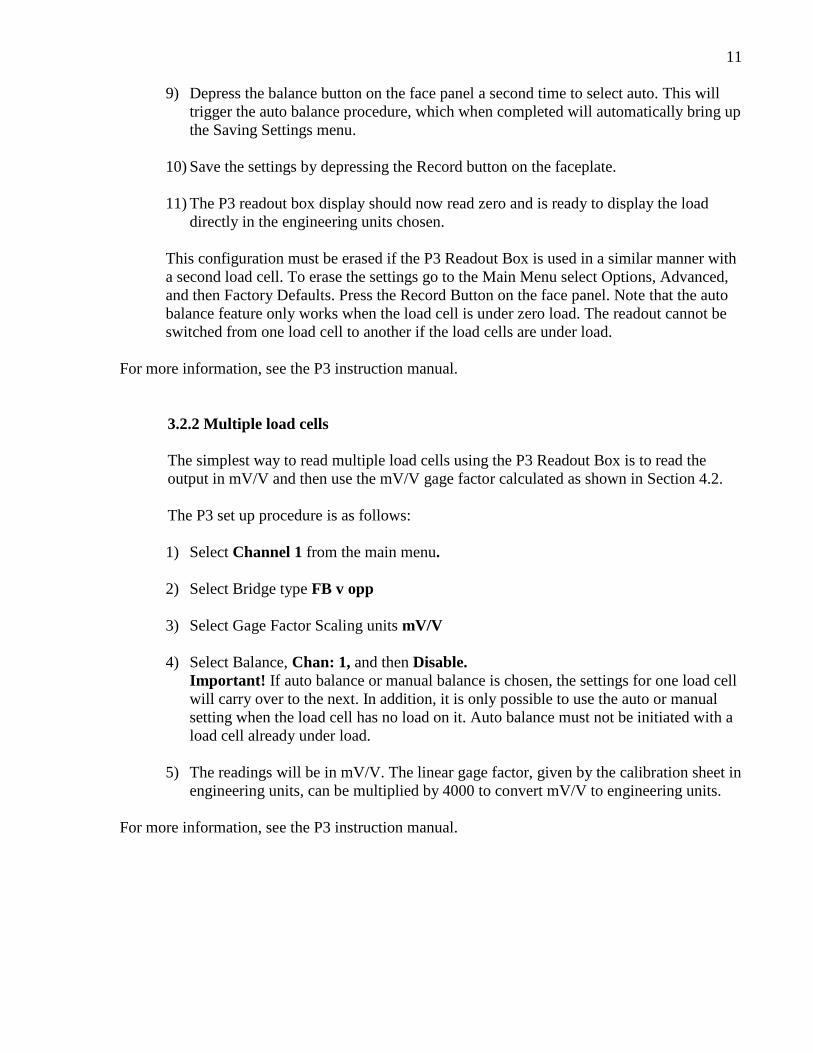
9) Depress the balance button on the face panel a second time to select auto. This will trigger the auto balance procedure, which when completed will automatically bring up the Saving Settings menu.
10) Save the settings by depressing the Record button on the faceplate.
11) The P3 readout box display should now read zero and is ready to display the load
directly in the engineering units chosen.
This configuration must be erased if the P3 Readout Box is used in a similar manner with a second load cell. To erase the settings go to the Main Menu select Options, Advanced, and then Factory Defaults. Press the Record Button on the face panel. Note that the auto balance feature only works when the load cell is under zero load. The readout cannot be switched from one load cell to another if the load cells are under load.
For more information, see the P3 instruction manual.
3.2.2 Multiple load cells
The simplest way to read multiple load cells using the P3 Readout Box is to read the output in mV/V and then use the mV/V gage factor calculated as shown in Section 4.2.
The P3 set up procedure is as follows: 1) Select Channel 1 from the main menu.
2) Select Bridge type FB v opp
3) Select Gage Factor Scaling units mV/V
4) Select Balance, Chan: 1, and then Disable.
Important! If auto balance or manual balance is chosen, the settings for one load cell will carry over to the next. In addition, it is only possible to use the auto or manual setting when the load cell has no load on it. Auto balance must not be initiated with a load cell already under load.
5) The readings will be in mV/V. The linear gage factor, given by the calibration sheet in engineering units, can be multiplied by 4000 to convert mV/V to engineering units.
For more information, see the P3 instruction manual.

12
4. DATA REDUCTION 4.1 Load Calculation When Reading Digits on the GK-502 The basic units utilized by Geokon for measurement and reduction of data from Model 3000 Load Cells when read using the GK 502 readout box are "digits". The calculation of digits is based on the following equation:
Digits = mV/V × 4000
Equation 1 - Digits Calculation Where; mV is the output of the Wheatstone bridge circuit in millivolts. V is the excitation supplied to the Wheatstone bridge circuit in volts. Load is calculated from digits by determining a change in reading (in digits) and then multiplying by the appropriate calibration factor. See the following equation:
L = (R1 - R0) × G × CF
Equation 2 - Load Calculation Using Linear Regression Where; L is the load in lb. or kg. R0 is the initial no-load reading. R1 is the current reading. G is the Linear Gage Factor as supplied on the Calibration Sheet (see Appendix C). CF is the conversion factor (optional) as listed in Table 1.
From→ To↓
Lbs.
Kg.
Kips
Tons
Metric Tons
Lbs. 1 2.205 1000 2000 2205 Kg. 0.4535 1 453.5 907.0 1000 Kips 0.001 0.002205 1 2.0 2.205 Tons 0.0005 0.0011025 2.0 1 1.1025
Metric Tons 0.0004535 0.001 0.4535 0.907 1 Table 1 - Engineering Units Conversion Multipliers
For example: A Model 3000 load cell has an initial no-load reading (R0) of 164 (regression zero reading can be found on the calibration sheet), a current reading (R1) of 2050, and a linear gage factor (G) of 148.7 lbs. per digit. Inputting the values into Equation 2 gives:
L = (2050 − 164) × 148.7 = 280,450 lbs.

13
Note that the equations assume a linear relationship between load and strain readings, and the linear coefficient is obtained using regression techniques, which may introduce a substantial nonlinearity around the zero reading. For greater accuracy, a polynomial expression to fit the data can be used:
L = AR1
2 + BR1 + C
Equation 3 - Load Calculation Using Polynomial Where; L is the load in lb., kgms, etc. R1 is the current reading. A and B are the coefficients derived from the calibration data. The C coefficient is derived by plugging the initial no-load reading, obtained in the field, into the polynomial equation. For example: A Model 3000 Load Cell has a current reading (R1) of 2050. The polynomial coefficients, A, B and C are -0.000286, 150 and -26,990, respectively. (C was derived by substituting the field no-load reading (R1) = 180 into the polynomial equation while setting P to zero.) Inputting the values into Equation 3 gives:
L = -1200 + 307,500 - 26990 = 279,300 lbs.
4.2 Load Calculation when reading the output in mV/V on a Model P3 Readout Box. The load is calculated using the following equation:
Load = (M1-M0) x J x CF
Equation 4 - Load Calculation Using mV/V Where; L is the load in lbs. or kg. or units chosen. M0 is the initial no-load mV/V reading. M1 is the current mV/V reading. J is the mV/V gage factor equal to the linear gage factor G*4000. CF is the conversion factor (optional) as listed in Table 1. In the example in the calibration sheet shown in Appendix C, J = 148.7 x 4000 = 594, 600 lb./mV/V. Alternatively, the value for the Full Scale mV/V can be used following the P3 instructions.

14
5. TROUBLESHOOTING 5.1 Readouts Problems with the readout box can be resolved by reading the standard reference plug. If the reading here is seen to change appreciably, this could be an indication of readout box instability. It is frequently advisable to have a backup readout available. The readout box should be kept clean and dry at all times. When not in use, store the readout in a warm and dry place so that as much moisture as possible is driven from the interior. Replace batteries as required. Both GK-502 and P3 Readout Boxes have low battery voltage indicators. In the case of the GK-502, when not in use the batteries should be kept charged as per the instruction manual. In the case of the P3 the two 'D' size alkaline batteries should be changed following the instructions of the Model P3 manual. Instability caused by electrical interference from nearby power lines, generators, welders, etc. can be minimized by making sure that the cable shield is connected to the readout box ground.
5.2 Load Cells Problems with the load cell are usually associated with cable damage or moisture getting into the system. Both problems can be minimized by protecting the cable from damage, by visual inspection of the cable in the event that problems arise, and by keeping the plug clean and dry at all times. Never carry the load cell by the cable. Check the cable for damage such as pulling out of the load cell or connector, crushed spots, cuts or kinks. If the cable is damaged, splice according to the instructions in Section 2.3. Check the load cell wiring. The wiring diagram and pinout are shown in Appendix B. If the load cell is working properly, the resistances between the various pins should be as shown in Table 2.
Pins Large Load Cells Small Load Cells A and B 525Ω 260Ω A and C 525Ω 260Ω A and D 700Ω 350Ω B and C 700Ω 350Ω B and D 525Ω 260Ω B and J 0Ω 0Ω C and D 525Ω 260Ω C and K 0Ω 0Ω F and any other pin Infinite Infinite
Table 2 - Load Cell Resistance Failure of the load cell to agree with the load as indicated by a hydraulic jack could be caused by one or more of the factors discussed in Section 1.2 and Appendix D.

15
APPENDIX A. SPECIFICATIONS
Available Ranges¹ 100, 150, 200, 300, 500, 600, 1000, 1500, 2000 kips Rated Capacities2 100 kN to 10,000 kN
Accuracy3 ±0.5% FSR Output 1.5 mV/V to 2.5 mV/V @ FSR
Linearity 0.5% FSR Resolution4 0.025% FSR
Repeatability5 0.1% FSR Temperature Effect 0.02% FSR/°C
Temperature Range −20 °C to +80 °C 0 °F to 110 °F
Overrange6 150% FSR Input Resistance 350 or 700 Ω
Output Resistance 350 or 700 Ω Excitation Voltage 2 to 15 VAC or DC
Maximum Excitation Voltage 30 V
Cable Type7 Three twisted pair (six conductor) 22 AWG Foil shield, PVC jacket, nominal OD=9.5 mm (0.375")
Table 3 - Model 3000 Load Cell Specifications Notes: 1 Other ranges available on request. 2 Other capacities available on request. Calibrations that exceed Geokon’s NIST traceable capacity of approximately 10,675 kN are subcontracted to an accredited testing laboratory. 3 The accuracy of the testing machine used to calibrate the cells is ±¼% FSR traceable to NIST. The system accuracy depends on end loading conditions as described in the text of this manual. If field conditions are well duplicated during actual calibration the accuracy should be within ±5 FSR. Failure to duplicate conditions can cause calibration variations of ±20% in extreme cases. 4 Minimum, depends on the readout instrument and technique. 5 Repeatability under the same loading conditions. This does not take into account hysteresis and
any changes in the loading conditions. 6 With no calibration shift. The maximum overrange without failure is 200% FSR for aluminum
cells, 300% to 400% FSR for steel cells, but both the no-load zero and the calibration may change if the load exceeds 150% FSR.
7 Other cable types available.

16
APPENDIX B. WIRING AND CONNECTOR PINOUTS The GK-502 is set up for remote sense of the excitation voltage at the load cell, which requires a six-conductor cable (three twisted pairs). If the load cell is not set up for remote sense and only has four conductors, then it will be necessary to modify the cable plug so that pins J and B and pins K and C are shorted together, otherwise the load cell cannot be read. The P3 readout box will not read remote sense therefore load cells that have been wired for remote sense must be rewired at the connector for non-remote sense. B.1 Wiring Diagram with P3 Readout
P-
P+
S+
S-
Shield
Load Cell
Ω700
350orΩ
V H
VH
Figure 6 - P3 Wiring
B.2 Wiring Diagram with Remote Sense (GK-502 Readout)
P-
P+
S+
S-
RS+
RS-
Shield
Load Cell
Ω700
350orΩ
V H
VH
Figure 7 - Remote Sense (GK-502) Wiring
17
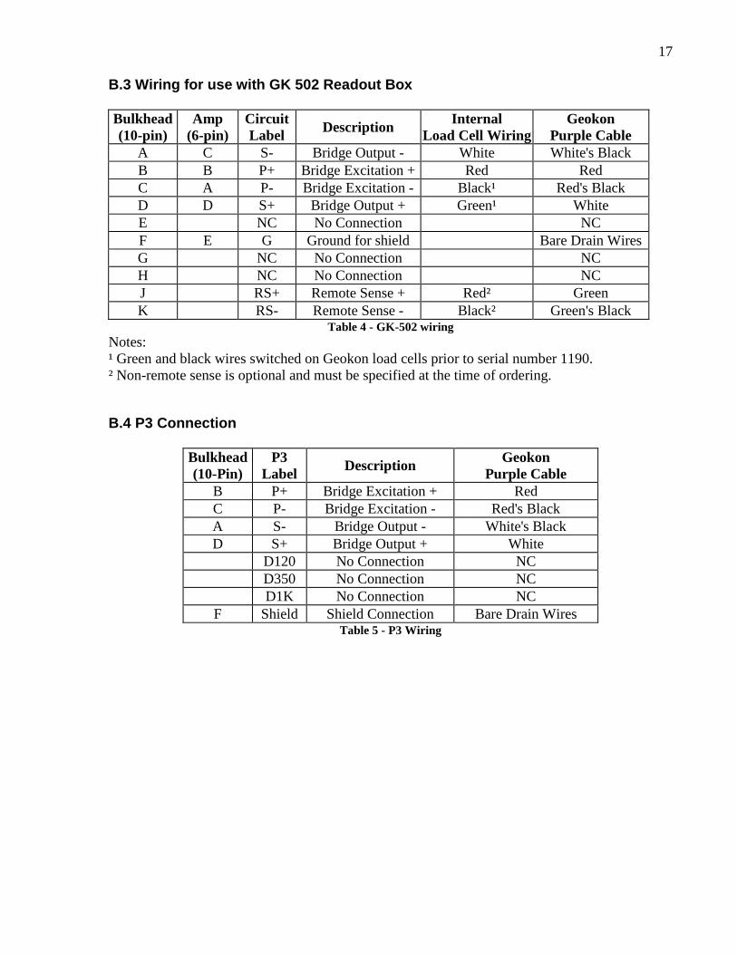
B.3 Wiring for use with GK 502 Readout Box Bulkhead (10-pin)
Amp (6-pin)
Circuit Label Description Internal
Load Cell Wiring Geokon
Purple Cable A C S- Bridge Output - White White's Black B B P+ Bridge Excitation + Red Red C A P- Bridge Excitation - Black¹ Red's Black D D S+ Bridge Output + Green¹ White E NC No Connection NC F E G Ground for shield Bare Drain Wires G NC No Connection NC H NC No Connection NC J RS+ Remote Sense + Red² Green K RS- Remote Sense - Black² Green's Black
Table 4 - GK-502 wiring Notes: ¹ Green and black wires switched on Geokon load cells prior to serial number 1190. ² Non-remote sense is optional and must be specified at the time of ordering.
B.4 P3 Connection
Bulkhead (10-Pin)
P3 Label Description Geokon
Purple Cable B P+ Bridge Excitation + Red C P- Bridge Excitation - Red's Black A S- Bridge Output - White's Black D S+ Bridge Output + White D120 No Connection NC D350 No Connection NC D1K No Connection NC
F Shield Shield Connection Bare Drain Wires Table 5 - P3 Wiring

18
APPENDIX C. SAMPLE CALIBRATION SHEET
Figure 8 - Model 3000 Calibration Sheet

19
APPENDIX D. LOAD CELL CALIBRATIONS - EFFECTS OF BEARING PLATE WARPING D.1 Introduction Load cells used to measure loads during testing of tiebacks, driven piles, and drilled shafts, give calculated loads that are frequently in disagreement with loads calculated based on hydraulic jack pressure and piston area. Because of this, there is a general lack of confidence in load cell data and the fault is often ascribed to manufacturing defects, or to improper, inaccurate calibration procedures. Nevertheless, it is also well known, throughout the industry, that the effects of eccentric loading and uneven and/or warped bearing plates, frictional effects on the bearing surfaces, do have a profound effect on load cell readings. The purpose of this technical note is to provide some insight into these effects.
D.2 Load Cell Calibration Procedures The usual calibration procedure is to use a testing machine to apply a load to a load cell. The measured load cell output is then correlated against the known applied load as measured by the testing machine. Usually, the testing machine has a hydraulic pressure applied to a piston of known cross section area. The testing machine is checked out periodically by running tests on a load cell traceable to NIST and there is generally little doubt about the accuracy of the testing machine. Accuracy's of ¼% FS ½% FS or 1% FS are normal. The calibration tests are usually performed between large, flat, parallel platens in the testing machine (sometimes with the addition of a spherical seat). The calibration is performed in this manner so that there is little or no eccentric loading, and no bending of the platens, only the elastic compression in the zone immediately bearing against the load cell.
D.3 Field Arrangement Such a state of affairs may not exist on the job site since the bearing surfaces next to the load cell are usually much less rigid, and liable to bending. This bending is particularly apparent if there is a mismatch in size between the load cell and the hydraulic jack. If the hydraulic jack is larger than the load cell there is a tendency for it to try to wrap the intervening bearing plate around the load cell. If the hydraulic jack is smaller than the load cell it will try to push the intervening bearing plate through the hole in the load cell. Thicker bearing plates will bend less, but the effect will never be entirely eliminated. The consequence of this bending can be quite large since the effect on the load cell is to cause it to either barrel out at its midsection if the jack is too small, or pinch in at its midsection if the jack is too big. For electrical resistance strain gage load cells, the gages are usually located on the outer surface of the load bearing cylinder at its midsection.

20
D.4 Effects of Jack Size on Load Cell Reading A series of tests were conducted in a testing machine to investigate the magnitude of the effect of jack size on load cell readings. A load cell with a bearing surface of 4" ID, 5¾" OD was used. Simulated jack A had a bearing surface of 2" ID, 4" OD. Simulated jack B had a bearing surface of 4" ID, 5¾" OD. Simulated jack C had a bearing surface of 6" ID, 8" OD. The maximum applied load was 150 tons.
Load Cell response to applied load (100%)
1" thick plate 2" thick plateJack
108%
100%
96%
102%
100%
98%
LC
J
LC
J
LC
J
A
B
C
(smaller)
(same size)
(bigger)
Table 6 - Effects of Jack Size on Readings
It can be seen from the results that if the jack is smaller than the load cell, the load cell will over-register, while a jack bigger than the load cell will cause the load cell to under-register. The effect is bigger if the bearing plate between jack and load cell is thinner. The correct bearing plate thickness will of course depend on the extent of the mismatch between jack and load cell. However, as a rough rule of thumb the following thicknesses should be required: Up to 100-200 kip load: 25 mm (1”) thick Up to 400 kip load: 37 mm (1.5”) thick Up to 1000 kip load: 50 mm (2“) thick Up to 2000 kip load: 75 mm (3”) thick

21
D.5 Conclusion The consequences of the above would seem to indicate that for best results the load cell calibration should be performed in the field with the actual hydraulic jack that will be used. Alternatively, if the calibration is done in the laboratory, the load cell and the jack should be placed in the testing machine at the same time. Failing that, the load cell should be loaded through a ring, having the same dimensions as the bearing surface of the hydraulic jack, positioned on the other side of a bearing plate of the correct thickness. In this way, some of the variables affecting the agreement between load cell readings and hydraulic jack readings can be removed and the agreement should be that much closer. This technical note has addressed only the subject of the size mismatch between load cells and hydraulic jacks. Other factors affecting the agreement between load cell readings and hydraulic jack load are important, thus frictional losses within the hydraulic jack can cause under-registering of jack load indications by as much as 15%. (Dunnicliff 1988' Section 13.2.6) Also annular style load cells are susceptible to end effects and eccentrically applied loads. The height of the load cell should exceed four times the wall thickness of the annulus and at least four strain gages should be used (Dunnicliff 1988' Section 13.2.6) increasing to eight or 12 in number as the size of the load cell increases. References: J. Dunnicliff. 1988. Geotechnical Instrumentation for Monitoring Field Performance, John Wiley & Sons, New York, NY: 577pp.