Embed Size (px)
Citation preview

This device complies with Part 15 of the FCC Rules. Operation is sub-ject to the following two conditions: (1) This device may not causeharmful interference, and (2) this device must accept any interferencereceived, including interference that may cause undesired operation.
iE90MULTIBAND FM TRANSCEIVER
INSTRUCTION MANUAL
WARNING: MODIFICATION OF THIS DEVICE TO RECEIVE CEL-LULAR RADIO TELEPHONE SERVICE SIGNALS IS PROHIBITEDUNDER FCC RULES AND FEDERAL LAW.
i
Thank you for purchasing this Icom product. The IC-E90MULTI BAND TRANSCEIVER is designed and built withIcom’s superior technology and craftsmanship. With propercare, this product should provide you with years of trouble-free operation.The IC-E90 is a tri-band, 50 MHz, 144 MHz, 430 MHz FMtransceiver that offers a wide-band AM, FM and WFM scan-ning receiver*. Not only you can hear your favorite TV pro-grams with the pre-programmed TV memories*, but you canalso listen to short wave, AM and FM broadcast radio stations, aircraft, various amateur bands and more.New DMS(Dynamic Memory Scan) bank scanning provides555 alphanumeric memory channels, including 50 bandedges, with a maximum of 18 banks or 100 channels perbank. You can pick and choose any desired channel forscanning from the 500 memories.The supplied BP-217 LITHIUM-ION BATTERY PACK provides full 5 W of output. Along with the energy conserving settings, theBP-217 provides up to 5 to 6 hours of operating time. Thenewly designed antenna also provides stable signal strength.We want to thank you for making your IC-E90 your radio ofchoice, and hope you agree with Icom’s philosophy of “tech-nology first.” Many hours of research and development wentinto the design of your IC-E90.
ïïFEATURESTri-band FM transceiverWide-band receiver
—Covers 495 KHz to 999.990* MHzNew DMS (Dynamic Memory Scan)
bank scanLithium-Ion technologyRugged palm sized, weather-resis-
tant constructionDTCS and CTCSS tone squelchSimple operation
*Available frequency range and/or the pre-pro-grammed TV memories may differ depends on ver-sion. See p. 85 for details.
FOREWORD

ii
IMPORTANT
READ ALL INSTRUCTIONS carefully and completelybefore using the transceiver.
SAVE THIS INSTRUCTION MANUAL — This in-struction manual contains important operating instructions forthe IC-E90.
EXPLICIT DEFINITIONS
The explicit definitions below apply to this instruction manual.
WORD
WARNING
CAUTION
NOTE
DEFINITION
Personal injury, fire hazard or electric shock may occur.
If disregarded, inconvenience only. No risk of personal injury, fire or electric shock.
Equipment damage may occur.
Icom, Icom Inc. and the Icom logo are registered trademarks of IcomIncorporated (Japan) in Japan, the United States, the UnitedKingdom, Germany, France, Spain, Russia and/or other countries.
SUPPLIED ACCESSORIES
Accessories included with the transceiver: Qty.q Li-Ion battery pack (BP-217) .......................................... 1w Wall charger* (BC-110D/DR) .......................................... 1e MB-83 (Swivel belt clip) ........................................... 1 setr Handstrap........................................................................ 1tAntenna (FA-S6270D; with 50 MHz band adapter) .. 1 set
*Not supplied with some versions.
q
w
e r t

iii
RRWARNING RF EXPOSURE! This device emitsRadio Frequency (RF) energy. Extreme caution should beobserved when operating this device. If you have any ques-tions regarding RF exposure and safety standards pleaserefer to the Federal Communications Commission Office ofEngineering and Technology’s report on EvaluatingCompliance with FCC Guidelines for Human RadioFrequency Electromagnetic Fields (OET Bulletin 65)
RRWARNING! NEVER hold the transceiver so that theantenna is very close to, or touching exposed parts of thebody, especially the face or eyes, while transmitting. Thetransceiver will perform best if the microphone is 1 to 2 in (2to 5 cm) away from the lips and the transceiver is vertical.
RRWARNING! NEVER operate the transceiver with aheadset or other audio accessories at high volume levels.Hearing experts advise against continuous high volume oper-ation. If you experience a ringing in your ears, reduce the vol-ume level or discontinue use.
RRDAMAGE WILL BE OCCUR IF THESE LIMITSARE EXCEEDED, when charging the IC-E90 with theBP-217 battery pack from the external DC power jack on theradio, the DC input voltage must between 10.5 to 11.5 V,except when using optional CP-19R Cigarette Lighter cable.
NEVER connect the transceiver to an AC outlet . Such aconnection will damage the transceiver.
NEVER connect the transceiver to a power source that isDC fused at more than 5 A. Accidental reverse connection willbe protected by this fuse, but higher fuse values will not giveprotection against such accidents and the transceiver will beruined.
DO NOT operate the transceiver near unshielded electricalblasting caps or in an explosive atmosphere.
AVOID using or placing the transceiver in direct sunlight orin areas with temperatures below –10°C (+14°F) or above+60°C (+140°F).
RF output power is automatically reduced to 0.5 W (Low) incold environments (below 0°C) while operating with the BP-217Li-Ion battery pack, to protect the battery pack. Keep the bat-tery pack warm, then select high power again. (p. 28)
The use of non-Icom battery packs/chargers may impairtransceiver performance and invalidate the warranty.
Even when the transceiver power is OFF, a slight current stillflows in the circuits. Remove the battery pack or case fromthe transceiver when not using it for a long time. Otherwise,the battery pack or installed batteries will become exhausted.
CAUTIONS

iv
FOREWORD ............................................. iIMPORTANT ............................................. iiEXPLICIT DEFINITIONS .......................... iiSUPPLIED ACCESSORIES ..................... iiCAUTIONS ............................................... iiiTABLE OF CONTENTS ........................... iv
q QUICK REFERENCE GUIDE ........ 1–6
w PANEL DESCRIPTION ................ 7–12Panel description ............................. 7Function display ............................. 11
e BATTERY CHARGING .............. 13–16Battery attachment ......................... 13Battery cautions ............................. 13Regular charging ........................... 14Rapid charging ............................... 15Battery case ................................... 16External power operation ............... 16
r BASIC OPERATION .................. 17–33Turning power ON ......................... 17Tuning step .................................... 18Setting a frequency ........................ 19Mode selection ............................... 20Operating band and receive mode
selection ......................................... 21Setting the squelch level ................ 22Receiving ....................................... 23RIT function ................................... 27Attenuator function ......................... 27Transmitting ................................... 28Repeater operation ........................ 29Duplex operation ............................ 31
Split operation ................................ 321750 Hz tone ................................. 33
t MEMORY/CALL CHANNELS .... 34–44General .......................................... 34Calling up memory channels ......... 36Programming memory channels .... 37Transferring memory contents
to VFO ........................................... 38Copying memory contents ............. 39Memory names .............................. 39Memory bank ................................. 41Memory clear ................................. 43Call channel ................................... 44
y SCAN OPERATION ................... 45–49Scan types ..................................... 45VFO scan ....................................... 46Frequency skip function ................. 47Skip channel setting ....................... 47Memory scan ................................. 48Scan notes ..................................... 49
u PRIORITY WATCH .................... 50–54Priority watch types ........................ 50Priority alert .................................... 50Priority watch operation ................. 51
i SET MODE ................................ 55–66Set mode ....................................... 55Set mode items ............................. 56
o OTHER FUNCTIONS ................ 67–78Programming a DTMF code .......... 67Transmitting a DTMF code ............ 68Clearing a DTMF memory ............. 69
Confirming a DTMF memory ......... 69Tone frequency and DTCS code .... 70Tone/DTCS squelch ....................... 71Pocket beep function ...................... 71Available tone frequencies ............. 72Available DTCS codes ................... 72Tone scan ...................................... 73Beep tones ..................................... 74Dial speed acceleration ................. 74Lock function .................................. 74Morse code synthesizer ................. 75Power save .................................... 75Time-out timer ................................ 76PTT lock ......................................... 76Auto power OFF ............................ 76Auto power ON .............................. 76Cloning function ............................. 77 [SP/MIC] jacks ............................... 77Resetting ........................................ 78
!0 HM-75A REMOTE CONTROLMICROPHONE ................................. 79
!1 TROUBLESHOOTING ..................... 80
!2 TV FREQUENCY TABLE ...........81–84
!3 SPECIFICATIONS ..................... 85–86
!4 OPTIONS ................................... 87–88
POCKET GUIDEDOC
TABLE OF CONTENTSqq
ww
ee
rr
tt
yy
uu
ii
oo
!!00
!!11
!!22
!!33
!!44
1
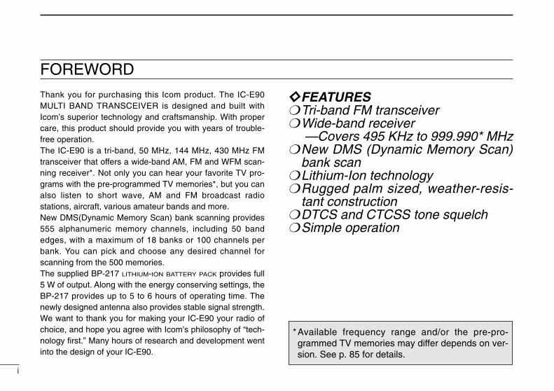
QUICK REFERENCE GUIDE1 Installing the battery packq Open the latch. Then, attach the BP-217 Li-Ion battery
pack or optional BP-216 battery case.•Be sure to observe the correct direction.•Charge Li-Ion battery pack before use.
w Lock the latch.
NOTE: The battery pack is provided uncharged. BE SURE tocharge the battery before using it with the transceiver.
D Installing the alkaline batteriesInstall 2 R6 (AA) size alkaline batteries into BP-216.•Be sure to observe the correct po-larity.
Keep battery contacts clean. It’sa good idea to clean battery ter-minals once a week.
Accessory attachmentDAttaching the swivel belt clip The supplied swivel belt clip is useful for easy attaching/detaching the transceiver to/from the belt.qAttach the stopper to
the transceiver withthe supplied screw.
wClip the belt clip toyour belt.
Battery pack orbattery case
Latch
q
w
stoppersuppliedscrew

2
1QUICK REFERENCE GUIDE
e Insert the transceiver to the end of theclip as shown at right.
•Once the transceiveris locked in place, itwill swivel 360degrees as shown atright.
To remove:rTurn the transceiver upside down, and then lift to release
the transceiver from the belt clip as shown at upper right.
DHandstrapSlide the handstrap through the loop onthe top of the belt clip as shown atright.
QU
ICK
RE
FE
RE
NC
E G
UID
E
iC-t90a
CAUTION!HOLD THE TRANSCEIVER TIGHTLY, WHEN ATTACHINGOR REMOVING THE TRANSCEIVER TO/FROM THEBELT CLIP.If the transceiver accidentally dropped and the swivel beltclip’s stopper is scratched, the swivel belt clip may not workproperly.

3
1 QUICK REFERENCE GUIDE
50 MHz band adapter
Attach the 50 MHz band adapter
Hold the base , then screw the antenna down.
for BC band to 50 MHz band, through to 800 MHz band
for WFM band to800 MHz band
Detach the top cap*
*KEEP the the anttenna top capin the safe place when it not in use.
D Installing the antennaInsert the supplied wide band antenna into the antenna con-nector and screw down the antenna as shown below.
•50 MHz band adapterAttach the 50 MHz band antenna adapter before operating 50 M Hz band or receiving the signal below 50 MHz band. Besure to use this 50 MHz band adapter during the operationbelow 50 MHz band. You can operate the whole band withthis adapter.
CAUTION!TRANSMITTING WITHOUT AN ANTENNA MAY DAMAGETHE TRANSCEIVER.
NEVER HOLD the anten-na when carrying the trans-ceiver.
KEEP the jack covers at-tached when the jack is notin use, to avoid bad con-tacts from dust and mois-ture.
NOTE:Commercially available antennas may increase transceiverperformance. An optional AD-92SMA ANTENNA CONNECTOR
ADAPTER is available to connect an external antenna with aBNC connector.

4
1QUICK REFERENCE GUIDE
Charging the Li-Ion battery pack
DCharging with the wall charger
q Push and hold [PWR] to turn the transceiver power OFF.w Insert the charger plug into the DC power jack of the trans-
ceiver.e Plug the charger into an AC wall outlet.r Charging starts and the battery indicator “ ” on the dis-
play blinks. t It takes approximately 15 hours to charge an empty BP-
217 Li-Ion battery pack.y Unplug the charger from the AC wall outlet when charging
is completed.
DCharging with the CP-19R Cigarette Lightercable (option)
q Insert the cigarette lighter adapter cable into the DC powerjack of the transceiver.
w Connect the CP-19R cigarette lighter adapter cable to thecigarette lighter socket.
e Charging starts and the battery indicator on the displayblinks.
NOTE:•The BP-217 can be charged while you operating the transceiver. (p. 5).
•Charging will be suspended during transmitting of the transceiver.• “CHG_F” appears when the charging is completed with the powerturned OFF.
•NEVER connect the cigarette lighter socket or external regulatedDC power supply directly to the transceiver. Such a connection willdamage the transceiver.
•Remove CP-19R from the transceiver when not using it. Otherwise,the vehicle battery will become exhausted.
IC-E90 with BP-217
BC-110D/DR
toDC power jack
to AC outlet
CP-19R (optional)
toDC powerjack
to a 12 V cigarette lightersocket
QU
ICK
RE
FE
RE
NC
E G
UID
E
5
1 QUICK REFERENCE GUIDE
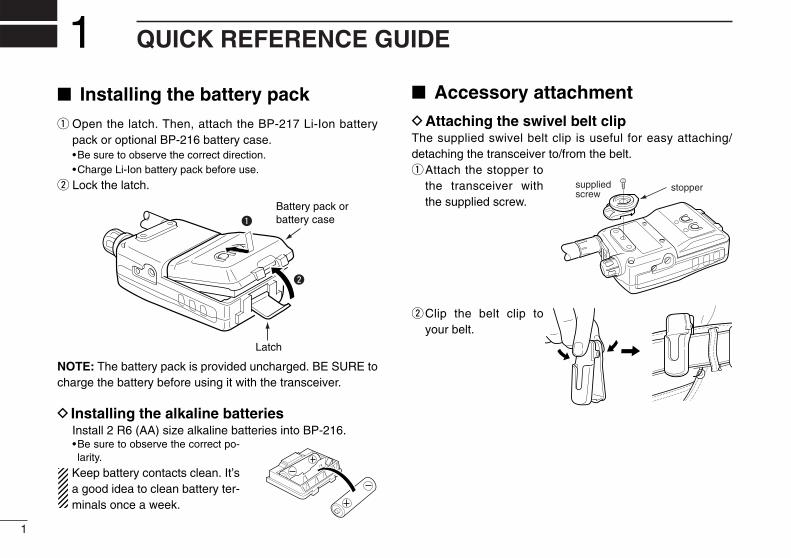
Rapid chargingThe optional BC-139 provides rapid charging of the batterypack.
CAUTION: To avoid damage to the transceiver, turn thetransceiver OFF while charging.
•Charging period: 2.5 hours (w/BP-217)
External power operationAn optional CP-19R cigarette lighter cable can be used forexternal power operation from cigarette lighter socket.
•External power supply range is between 5.5–11.0 V DC. NEVER connect over 11.5 V DC directly into the DCpower jack of the transceiver. DAMAGE WILL OCCURIF THESE LIMITS ARE EXCEEDED.
•BE SURE to use the CP-19R when connecting a regu-lated 12 V DC power supply.
•The maximum output power is 5.0 W regardless of thepower supply voltage.
•Remove the cables from the transceiver when not usingit. Otherwise, the vehicle battery will become exhausted
CP-19R (optional)
toDC powerjack
to a 12 V cigarette lightersocket
Turn powerOFF.
Check the orientation.
BP-217Li-Ion battery pack
to AC outlet
BC-139 (optional)desktop charger
BC-123E(supplied with BC-139)
to [AC ADAPTER] jack
AAdapter (suppliedwith BC-139)
LEDCharging: OrangeFinished: Green
Charging terminal

6
1QUICK REFERENCE GUIDE
Your first contactNow that you have your IC-E90 ready to operate, you areprobably excited to get on the air. We would like to take youthrough a few basic operation steps to make your first “OnThe Air” an enjoyable experience.
DFirst contactqPush and hold [PWR] for 1 sec. to turn the transceiver
power ON.•The function display shows “ICOM,” current voltage then the op-erating frequency.
wPush [BAND] several times until the desired operatingband (VHF; 51.000, 145.000 or UHF; 430.000 as default)appears on the display.
ePush [Y](or [Z]) several times to adjust to the desiredaudio level.
rRotate [DIAL] to select the receive frequency.
‘Direct frequency input’ via the keypad also available. (p. 19)
tHold the transceiver approximately 5 cm. (2 in) from yourmouth.
yPush and hold [PTT], then speak at your normal voicelevel.
uRelease [PTT] switch to receive.
•Repeat steps, t, y and u to continue communication.
r
e
q
w
yu
[DIAL]
[PTT]
[UP/DOWN]
[BAND]
[PWR]
[Mic]
QU
ICK
RE
FE
RE
NC
E G
UID
E
[EXAMPLE] Setting thereceive frequency to439.350 MHz

Panel description q POWER SWITCH [PWR]Push for 1 sec. to turn the transceiver power ON and OFF.
w BAND SWITCH [BAND]Push to select the operating band (50MHz, Air, VHF,
UHF, etc.). (p. 21)Push to select the memory bank or push to proceed the
memory name cursor while programming the memoryoption. (pgs. 39, 41)
Push for 1 sec. for morse code synthesizer announce-ment. (p. 75)
While pushing [PTT], this key sends a DTMF “D”.
e UP/DOWN SWITCHES [Y]/[Z]Push to adjust the audio level by default. (p. 17)Push to adjust the frequency when [Y]/[Z] and [DIAL]
are exchanged by pushing [1 V↔D] for 1 sec. (p. 23)
r MONITOR SWITCH [SQL] (p. 22)Push and hold to temporarily open the squelch and
monitor the operating frequency.While pushing, rotate the tuning dial to set the squelch
threshold level.
t TRANSMIT/RECEIVE INDICATORLights green while receiving a signal or when the
squelch is open; lights red while transmitting.Flashes green for 5 sec. when the scan stop LED func-
tion is in use and a scan is stopped. (pgs. 49, 62)
t
u
i
o
!0
!1
!2
!3
!4
Keypad !6–@5
!5
e
r
q
w
y
Function display
Speaker
Microphone
7
2 PANEL DESCRIPTION

8
2PANEL DESCRIPTION
y PTT SWITCH [PTT]Push and hold to transmit in 50/144/430 MHz amateur
bands; release to receive. (p. 28)•When WFM or AM mode is selected, transmission is impossible.
u ANTENNA CONNECTOR (p. 3)Connects the supplied antenna.
i EXTERNAL SPEAKER AND MICROPHONE JACKS[SP/MIC]Connects an optional speaker-microphone or headset, ifdesired. The internal microphone and speaker will notfunction when any external equipment is connected. (Seepgs. 87, 88 for a list of available options.)
o TUNING DIAL [DIAL]Rotate [DIAL] to set operating frequencies, memory
channels, set mode contents, etc. (pgs. 19, 36, 55)While pushing [SQL], sets the squelch level. (p. 22)While pushing [BAND], sets the operating band in VFO
mode. (p. 21)While pushing [Y]/[Z], adjusts the audio level (when
[Y]/[Z] and [DIAL] are not exchanged). (p. 17)
!0 EXTERNAL DC POWER JACK [DC 11.0 V]Allows charging of the BP-217 using the BC-110D/DR
wall charger, or using an optional CP-19R cigarettelighter cable.
To connect regulated power supply with optional CP-19R cigarette lighter cable.
!1 MODE/SCAN SWITCH [MODE SCAN]Push to select the operating mode (FM, WFM,
AM). (p.21)Push for 1 sec. to start a scan. (p.46)
While pushing [PTT], this key sends the DTMF code “F”(#).
!2 VFO SWITCH [VFO MHz]Selects and toggles between VFO A and B.
(p. 20)Selects and toggles between the 1 MHz or 10
MHz tuning steps when pushed for 1 sec. (p. 18)
Returns to previous operating condition while setting fre-quency or memory channel, or while in set mode.
While pushing [PTT], this key sends the DTMF code “A”.
!3 MEMORY SWITCH [MR S.MW] Selects and toggles between memory mode
and memory bank. (p. 20)Push [MR S.MW] for 1 sec. to enter memory
write condition. (p. 37)Push for 2 sec. to write the operating frequency into the
selected memory channel in VFO mode.•Keep pushing for 2 sec. or more to automatically select thenext memory channel, if desired. (p. 38)
Push for 2 sec. to transfer the displayed frequency intothe VFO in memory mode. (p. 38)
While pushing [PTT], this key sends the DTMF code “B”.
MRS.MW
B
VFOMHz
A
MODESCAN
ww
PAN
EL
DE
SC
RIP
TIO
N

9
2 PANEL DESCRIPTION
!4 CALL/LOCK SWITCH [CALL/TV LOCK]Toggles between call channel, TV channel*,
and VFO mode in sequence. (p. 20)*Depends on version.
Push for 1 sec. to toggle the lock function ON and OFF.(p. 74)• “é” appears while the key lock function is in use.
While pushing [PTT], this key sends the DTMF code “C”.
!5 DTMF MEMORY SWITCH [• DTMF.M]Push for 1 sec. to enter the DTMF memory
channel. (p. 67) Inputs MHz digit for frequency input. (p. 19)
While pushing [PTT], this key sends the DTMF code “E”(M).
!6 VOLUME/DIAL SWITCH [1 V↔D]Push for 1 sec. to exchange [Y]/[Z] and
[DIAL] functions. (p. 23)• “VOL” appears when the tuning dial functions as avolume control.
Inputs digit ‘1’ for frequency input, memory channel se-lection, etc.
While pushing [PTT], this key sends the DTMF code “1”.
!7 TONE SWITCH [2 TONE] (p. 70)Push for 1 sec. to activate the following tone
functions in order.
•Subaudible tone encoder — “T” appears. (p. 29)•Tone squelch — “T SQL” appears. (p. 71)•Pocket beep — “T SQLS” appears. (p. 71)•DTCS squelch — “DTCS” appears. (p. 71)•DTCS beep — “SDTCS” appears. (p. 71)•No tone operation — no tone indicator appears.
Inputs digit ‘2’ for frequency input, memory channel se-lection, etc.
While pushing [PTT], this key sends the DTMF code “2”.
!8 OUTPUT POWER SWITCH [3 H/L] (p. 28)Push for 1 sec. to toggle the output power be-
tween high and low.• “LOW” appears when low output power is selected.
Inputs digit ‘3’ for frequency input, memory channel se-lection, etc.
While pushing [PTT], this key sends the DTMF code “3”.
!9 DUPLEX SWITCH [4 DUP] (pgs. 29, 31)Push for 1 sec. to activate the following duplex
functions in order.•Minus duplex operation — “–DUP” appears.•Plus duplex operation — “DUP” appears.•Simplex operation — no duplex indicator appears.
Inputs digit ‘4’ for frequency input, memory channel se-lection, etc.
While pushing [PTT], this key sends the DTMF code “4”.
4DUP
3H / L
2TONE
1V D
.DTMF.M
CALL/TVLOCK
C

10
2PANEL DESCRIPTION
@0 FREQUENCY SKIP SWITCH [5 SKIP]Push for 1 sec. to turn the frequency skip func-
tion ON and OFF in VFO mode. (p. 47)• “P SKIP” appears when the frequency skip functionis in use.
Push for 1 sec. to set the memory channel as the fol-lowing skip channel in memory mode in order. (p. 48)•Skip channel — “SKIP” appears. •Frequency skip channel — “P SKIP” appears. •Non-skip channel — no skip indicator appears.
Push for 1 sec. to program a paused frequency as askip frequency while scanning. (p. 46)
Inputs digit ‘5’ for frequency input, memory channel se-lection, etc.
While pushing [PTT], this key sends the DTMF code “5”.
@1 MEMORY NAME SWITCH [6 M.N]Push for 1 sec. to turn the memory name indi-
cation ON and OFF. (p. 40)•Frequency appears for nameless memory chan-nels.
Inputs digit ‘6’ for frequency input, memory channel se-lection, etc.
While pushing [PTT], this key sends the DTMF code “6”.
@2 TONE SCAN SWITCH [7 T.SCAN]Push for 1 sec. to start a tone scan. (p. 73) Inputs digit ‘7’ for frequency input, memory
channel selection, etc.
While pushing [PTT], this key sends the DTMF code “7”.
@3 SET MODE SWITCH [8 SET]Push for 1 sec. to enter the set mode. Push to
select the displayed set mode item after se-lecting with [DIAL] while in the set mode. (p. 55)
Inputs digit ‘8’ for frequency input, memory channel se-lection, etc.
While pushing [PTT], this key sends the DTMF code “8”.
@4 TUNING STEP SWITCH [9 TS]Push for 1 sec. to select the tuning step.
(p. 18) Inputs digit ‘9’ for frequency input, memory
channel selection, etc.While pushing [PTT], this key sends the DTMF code “9”.
@5 RIT/ATTENUATOR SWITCH [0 RIT]Push for 1 sec. to enter the RIT/attenuator set
mode. Push to select the item after selectingwith [DIAL]. (p. 27)
•RIT function is available for 630.000 MHz and above.•Attenuator for 629.995 MHz or less only.
Inputs digit ‘0’ for frequency input, memory channel se-lection, etc.
While pushing [PTT], this key sends the DTMF code “0”.
0RIT
9TS
8SET
7T.SCAN
6M.N
5SKIP
ww
PAN
EL
DE
SC
RIP
TIO
N

11
2 PANEL DESCRIPTION
Function display
q FREQUENCY READOUTShows the operating frequency, set mode contents, etc.•The smaller “75,” “50” and “25” to the right of the readout indi-cate 0.75, 0.5 and 0.25 kHz, respectively.
•The decimal point of the frequency flashes during scan.
w LOCK INDICATOR (p. 74)Indicates that the lock function is in use.
e RECEIVE MODE INDICATORS (p. 21)Shows the receive mode.•AM, FM and WFM are available.
r DUPLEX INDICATORS (pgs. 29, 31)Appears when semi-duplex operation (repeater operation)is in use.• “–DUP” appears when minus duplex is selected; “DUP” only, ap-pears when plus duplex is selected.
q
w e r t y u
io
!0
!1!2!5 !3!4

12
2PANEL DESCRIPTION
t TONE INDICATORS (p. 70)Appear when the following tone functions are activated.
•Subaudible tone encoder — “T” appears. (p. 29)•Tone squelch — “T SQL” appears. (p. 71)•Pocket beep — “T SQLS” appears. (p. 71)•DTCS squelch — “DTCS” appears. (p. 71)•DTCS beep — “SDTCS” appears. (p. 71)
“S” flashes when the correct tone or code is receivedduring pocket/DTCS beep operation. (p. 71)
y RIT INDICATOR (p. 27)Appears when the RIT (Receive Incremental Tuning) func-tion for 630.000 MHz and above is in use.
u SKIP SCAN INDICATOR (p. 47) “SKIP” appears when a selected memory channel is set
as a skip channel. “PSKIP” appears when the memory channel frequency
is set as a skip frequency in memory mode. “P SKIP” appears when the frequency skip function is
turned ON in VFO mode.
i PRIORITY WATCH INDICATOR (p. 50)Appears when priority watch is in use.
o MEMORY MODE INDICATOR (p. 20)Appears when a memory channel is selected.
!0 MEMORY CHANNEL READOUT (p. 20)Shows the memory or call channel number, etc.
!1 S/RF INDICATORS (p. 28)Shows the relative signal strength while receiving. Showsthe relative output power while transmitting.
!2 LOW POWER INDICATOR (p. 28)Appears when low output power is selected.
!3 VOLUME EXCHANGE INDICATOR (p. 23)Appears when the functions of tuning dial and [Y]/[Z]switches are exchanged.
!4 BATTERY INDICATORSBoth segments appear when the batteries have ample
capacity. •They do not appear when operating with an external powersource.
Only the right segment “ ” appears when the batteriesare nearing exhaustion.
Blinks while charging the attached Li-Ion battery pack.
!5 ATTENUATOR INDICATOR (p. 27)Appears when the attenuator is in use.
ww
PAN
EL
DE
SC
RIP
TIO
N

Battery attachmentq Attach the BP-217 Li-Ion battery pack or optional BP-216
battery case.•Be sure to observe the correct direction.•Charge Li-Ion battery pack before use.
w Lock the latch.
DOperating periodsThe operating periods with BP-217 are:
50 MHz Approx. 6 hr.144 MHz Approx. 5 hr.440 MHz Approx. 5 hr.
at high power, Tx : Rx : Standby = 1:1:8
Battery cautionsNEVER incinerate used battery packs. Internal battery gasmay cause an explosion.
NEVER immerse the battery pack in water. If the battery packbecomes wet, be sure to wipe it dry BEFORE attaching it tothe transceiver.
NEVER short terminals of the battery pack. Also, current mayflow into nearby metal objects so be careful when placing bat-tery packs in handbags, etc.
If your battery pack seems to have no capacity even afterbeing charged, completely discharge it by leaving the powerON overnight. Then, fully charge the battery pack again. If thebattery pack still does not retain a charge (or very little), anew battery pack must be purchased.
Use Icom battery packs, chargers and cables only. The use ofnon-Icom products may impair transceiver performance andinvalidate the warranty.
Even when the transceiver power is OFF, a slight current stillflows in the circuits. Remove the battery pack or case fromthe transceiver when not using it for a long time. Otherwise,the battery pack or installed batteries will become exhausted.
Battery pack orbattery case
Latch
q
w
3 BATTERY CHARGING
13

14
3BATTERY CHARGING
Regular chargingPrior to using the transceiver for the first time, the batterypack must be fully charged for optimum life and operation.
CAUTION: To avoid damage to the transceiver, turn thetransceiver OFF while charging.
•Recommended temperature range for charging:0°C to +35°C; +32°F to +95°F
•Use the wall charger* (BC-110AR/DR) only. NEVER use an-other manufactures’ charger.*Not supplied with some versions.
•An optional cable CP-19R (for 12 V cigarette lighter socket)can be used instead of the AC adapters of the above charg-ers.
DBattery indicatorsThe battery indicators blink while charging but do not indicatethe power condition.
“CHG_F” appears when the charging is completed. Discon-nect the wall charger in this case.
q Attach the battery pack to the transceiver.w Be sure to turn the transceiver power OFF.e Connect the AC adapter* (BC-110D/DR) as shown below.
*Not supplied with some versions.
r Remove any cables from the [DC11V] jack.
•Charging period: 15 hours (w/BP-217)
ee
BA
TT
ER
YC
HA
RG
ING
IC-E90 with BP-217 BC-110D/DR
to AC outlet
to DC powerjack
to a 12 V cigarette lightersocket
CP-19R (optional)

15
3 BATTERY CHARGING
Rapid chargingThe optional BC-139 provides rapid charging of the batterypack.•Charging period: 2.5 hours (w/BP-217)
CAUTION: To avoid damage to the transceiver, turn it OFFwhile charging.
•Recommended temperature range for charging:0°C to +35°C; +32°F to +95°F
•NEVER connect 2 chargers to the [AC ADAPTER] and[DC13.5V] jacks of BC-139.
•Use the supplied BC-123E for the BC-139 desktop charger.Connect BC-123E to the [AC ADAPTER] jack.
•NEVER use another manufactures’ charger. •An optional cable CP-19R (for 12 V cigarette lighter socket)can be used instead of the supplied AC adapter. Connectone of these to the [DC11V] jack in this case.
If the charge indicator blinks orange, there may be a prob-lem with the battery pack (or charger). Re-insert the bat-tery pack or contact your dealer.
Turn powerOFF.
Check the orientation.
BP-217Li-Ion battery pack
to AC outlet
BC-139 (optional)desktop charger
BC-123E(supplied with BC-139)
to [AC ADAPTER] jack
AAdapter (suppliedwith BC-139)
LEDCharging: OrangeFinished: Green
Charging terminal
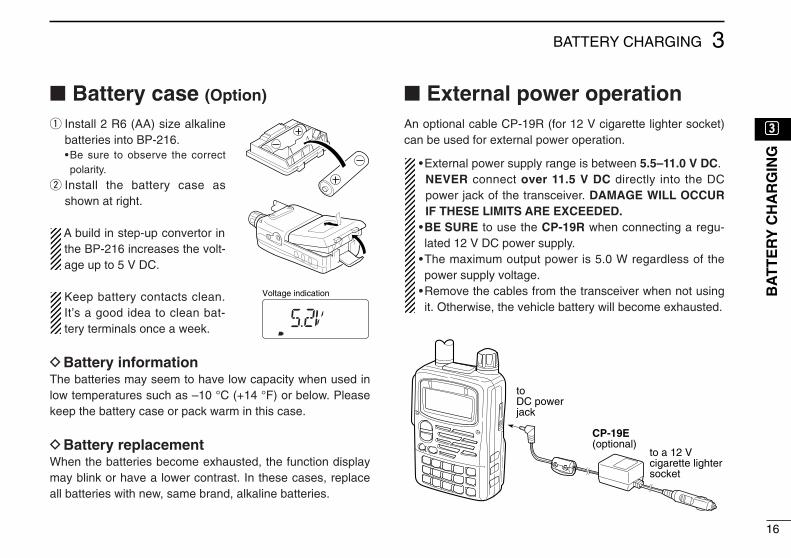
Battery case (Option)
q Install 2 R6 (AA) size alkalinebatteries into BP-216.•Be sure to observe the correctpolarity.
w Install the battery case asshown at right.
A build in step-up convertor inthe BP-216 increases the volt-age up to 5 V DC.
Keep battery contacts clean.It’s a good idea to clean bat-tery terminals once a week.
DBattery informationThe batteries may seem to have low capacity when used inlow temperatures such as –10 °C (+14 °F) or below. Pleasekeep the battery case or pack warm in this case.
DBattery replacementWhen the batteries become exhausted, the function displaymay blink or have a lower contrast. In these cases, replaceall batteries with new, same brand, alkaline batteries.
External power operationAn optional cable CP-19R (for 12 V cigarette lighter socket)can be used for external power operation.
•External power supply range is between 5.5–11.0 V DC. NEVER connect over 11.5 V DC directly into the DCpower jack of the transceiver. DAMAGE WILL OCCURIF THESE LIMITS ARE EXCEEDED.
•BE SURE to use the CP-19R when connecting a regu-lated 12 V DC power supply.
•The maximum output power is 5.0 W regardless of thepower supply voltage.
•Remove the cables from the transceiver when not usingit. Otherwise, the vehicle battery will become exhausted.
16
3BATTERY CHARGING
ee
BA
TT
ER
YC
HA
RG
ING
to a 12 V cigarette lightersocket
CP-19E (optional)
toDC powerjack
Voltage indication

17
4 BASIC OPERATION
Turning power ONDTurning power ONq Make sure alkaline batteries are installed in the battery
case or the battery pack is charged, and attach them. (p. 13)
w Push [PWR] for 1 sec. to turn the power ON.•The function display shows “ICOM,” current voltage then the op-erating frequency.
•Repeat this step to turn power OFF.
The opening message can be turned ON or OFF in the ex-panded set mode 1. (p. 64)
DSetting volume levelThe audio level can be adjusted through 32 levels.Push [Y] or [Z] to set the desired audio level.
•Rotating the tuning dial while pushing [Y] or [Z] also sets theaudio level.
• [Y]/[Z] and [DIAL] can be exchanged by [1 V↔D]. (p. 23)
DVolume level indicationThe frequency display shows the volume level during settingas shown below.
[∫]
[√]
Shows volume level.
[PWR]
FM SKIPP
Frequency indication
Opening message ‘ICOM’
Voltage indication
Indication Audio level0 (no sound)
19–23 (default)
24–27
28–30
31 (Maximum)
1–11
12–18

18
4BASIC OPERATION
Tuning stepWhen using the tuning dial to changethe frequency, or when a scan functionis activated, the frequency changes inincrements determined by the set tun-ing step. Tuning steps can be selectedfor each band. This transceiver has 13tuning steps as follows:•5 kHz •6.25 kHz •8.33* kHz•9* kHz •10 kHz •12.5 kHz•15 kHz •20 kHz •25 kHz•30 kHz •50 kHz •100 kHz•200 kHz
*Depends on version.
DSetting the tuning stepq Push [9 TS] for 1 sec. to enter tuning
step set mode.• “TS” appears.
w Rotate [DIAL] to select the desiredtuning step.•Rotating the tuning dial while pushing [9TS] also selects the tuning step.
•Tuning step can be set in VFO andmemory modes.
e Push [9 TS] or [VFO] to exit.
DMHz tuning stepThis is useful to change the frequencyrapidly.
q Select VFO mode with [VFO].w Push [VFO MHz] for 1 sec. to select
1 MHz tuning step.e Push [VFO MHz] for 1 sec. again to
select 10 MHz tuning step, if re-quired.
r Rotate [DIAL] to select the desiredMHz frequency.
t Push [VFO] to exit MHz tuning step.
FM SKIPP
FM SKIPP
1 MHz tuning step
10 MHz tuning step
5 kHz tuning step
20 kHz tuning step
[9 TS]
[DIAL]
[VFO MHz]
rr
BA
SIC
OP
ER
AT
ION

19
4 BASIC OPERATION
DSetting the frequency with keypadq Select VFO mode with [VFO].w Push the desired numeral buttons until inputting 1 kHz digit to set the frequency.
•When you want to change the 100 kHz digit and below, push [•] first, then the numeral but-tons.
•Acceptable digits for the 1 kHz digit depend on the 10 kHz digit.
Setting a frequencyPush numeral keys and [•] to input thedesired frequency.•Frequency can be set irrelevant of the se-lected band.
•When inputting a frequency outside of thefrequency range, the previously selectedfrequency is automatically selected after in-putting 1 kHz digit.
*Available frequency range and/or thepre-programmed TV memories maydiffer depends on version. See p. 85for details.
1V D
2TONE
3H / L
4DUP
5SKIP
6M.N
0RIT
7T.SCAN
8SET
9TS
.DTMF.M
[VFO]
2TONE
4DUP
.DTMF.M
0RIT
6M.N
8SET
.DTMF.M
FM
FM
FM
FM
FM
SKIPP
SKIPP
SKIPP
SKIPP
SKIPP
0RIT
4DUP
5SKIP
3H / L
3H / L
4DUP
8SET
.DTMF.M
FM
FM
FM
FM
FM
FM
FM0RIT
SKIPP
SKIPP
SKIPP
SKIPP
SKIPP
SKIPP
SKIPP
•Setting to 0.684 MHz •Setting to 433.580 MHz •Changing 100 kHz andbelow.
Setting 433.580 MHz to433.240 MHz.
20
4BASIC OPERATION
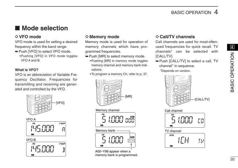
Mode selectionDVFO modeVFO mode is used for setting a desiredfrequency within the band range.Push [VFO] to select VFO mode.
•Pushing [VFO] in VFO mode togglesVFO A and B.
What is VFO?VFO is an abbreviation of Variable Fre-quency Oscillator. Frequencies fortransmitting and receiving are gener-ated and controlled by the VFO.
DMemory modeMemory mode is used for operation ofmemory channels which have pro-grammed frequencies.Push [MR] to select memory mode.
•Pushing [MR] in memory mode togglesmemory channel and memory bank indi-cations.
•To program a memory Ch, refer to p. 37.
DCall/TV channelsCall channels are used for most-often-used frequencies for quick recall. TVchannels* can be selected with[CALL/TV].Push [CALL/TV] to select a call, TV
channel* in sequence.*Depends on version.
FM
FM
[MR]
Memory channel
Memory bank
A00–Y99 appear when a memory bank is programmed.
[VFO]
VFO A
VFO B
FM SKIPP
FM SKIPP
rr
BA
SIC
OP
ER
AT
ION
FM
FMW
[CALL/TV]
Call channel
TV channel

Operating band and receive mode selectionDSelecting the operating
bandThe transceiver can receive the BC(broadcast)* bands, 5 MHz* band, 50 MHz* band, WFM* bands, Air* band,144 MHz (VHF) band, 220 MHz* band,300 MHz* band, 430 MHz (UHF) bandor 800 MHz* band.
NOTE:Available frequency range maydiffer depends on version.
q Select VFO mode with [VFO].w Push [BAND] several times to select
the desired band.•Rotating the tuning dial while pushing[BAND] also selects the operating band.
[VFO][BAND]
21
4 BASIC OPERATION
DSelecting the receive modeReceive modes are determined by thephysical properties of the radio signals.The transceiver has 3 receive modes:FM, AM and WFM modes. Typically, AMmode is used for the avionics band(108– 135.975 MHz) and WFM is usedfor FM broadcast stations (88–107.75MHz).
When pushing [PTT], a beep tonesounds indicating the mode is notFM mode. The transceiver cannottransmit in AM or WFM mode.
FM SKIPP
FM SKIPPW
AM SKIPP
FM mode
WFM mode
AM mode
MODESCAN
MODESCAN
MODESCAN
Pushto toggle the operating mode.
SKIPP
SKIPP
SKIPP
SKIPP SKIPP
SKIPP SKIPP
SKIPP
SKIPPAM FM
BAND
FMFMSKIPPFM
AM
FM
FM
AM
FMW
BC (broadcast) bands 5 MHz bands 50 MHz band WFM bands*
800 MHz band*
UHF band 300 MHz band*
Air bands*
VHF band220 MHz band*
0.495–1.620 MHz 1.625–34.995 MHz 35.000–87.995 MHz*
108.000–135.995 MHz
88.000–107.995 MHz*
550.000–999.990 MHz
383.000–549.995 MHz 255.000–383.995 MHz 220.000–254.995 MHz 136.000–221.995 MHz
Push [BAND] several times to select the desired band.
*UK and Italy versions only.

Setting the squelch level
22
4BASIC OPERATION
The squelch circuit mutes the receivedaudio signal depending on the signalstrength. The transceiver has 9 squelchlevels, a continuously open setting andan automatic squelch setting.
DSetting the squelch levelq While pushing and holding [SQL], ro-
tate [DIAL] one-click to display thecurrent squelch level.
w Rotate [DIAL] successively to adjustthe squelch level.• “LEVEL1” is loose squelch and“LEVEL9” is tight squelch.
• “AUTO” indicates automatic level adjust-ment with a noise pulse count system.
e Release [SQL] to return to the previ-ous indication.
[Squelch level indication]
DMonitor functionThis function is used to listen to weaksignals or to open the tone squelchmanually.Push and hold [SQL] to monitor the
operating frequency.
The [SQL] switch can be set as amonitor ON/OFF switch in set mode.(p. 60)
[SQL]
Blinks while monitoring.
FM SKIPP
rr
BA
SIC
OP
ER
AT
ION
[SQL]
[DIAL]
Indication Squelch levelOpen
Automatic (default)
Level 1 (loose)
Level 2
Level 3
Level 4
Level 5
Level 6
Level 7
Level 8Level 9 (tight)

23
4 BASIC OPERATION
ReceivingDSetting volume levelPush [Y] or [Z] to set the desired audio level.
•Rotating the tuning dial while pushing [Y] or [Z] also sets theaudio level.
DSetting squelch levelq While pushing [SQL], rotate [DIAL] to select the squelch
level.• “LEVEL1” is loose squelch and “LEVEL9” is tight squelch.
w Release [SQL] to return to the previous indication.
DExchange [DIAL] and [YY]/[ZZ] functionsThe functions of tuning dial and [Y]/[Z] switches can be ex-changed, if desired.
Push [1 V↔D] for 1 sec. to exchange the functions of thetuning dial and [Y]/[Z] switches.• “VOL” appears when the functions are exchanged.
[DIAL]
[Y]/[Z]
Default settingFrequency settingMemory channel settingScan direction settingSet mode setting
Volume setting
Volume setting
Exchanged setting
Frequency settingMemory channel settingScan direction settingSet mode setting
FM
VOL
SKIPP
[DIAL]
[∫][√]
Appears when the functions are exchanged.
[1 V D]
[DIAL]
[SQL] [∫][√]

24
4BASIC OPERATION
DReceiving FM broadcast[EXAMPLE]: Receiving 88.200 MHz.
q Select VFO mode with [VFO].w For direct frequency input, push [8], [8], [•], [2], [0], [0].
•Skip e and t in this case.
e Push [BAND] several times to select the FM broadcastband.•Default frequency (FM broadcast band): 76.000 or 88.000 MHz
r Push [MODE] several times to select WFM mode if re-quired.
t Rotate [DIAL] to set 88.200 MHz.y When a signal is received:
The TX/RX indicator lights green.Squelch opens and audio is emitted from the speaker.The S/RF indicator shows the relative signal strength.
DReceiving amateur bands[EXAMPLE]: Receiving 145.600 MHz.
q Select VFO mode with [VFO].w For direct frequency input, push [1], [4], [5], [•], [6], [0], [0].
•Skip e and t in this case.
e Push [BAND] several times to select the 144 MHz band.•Default frequency (144 MHz band): 145.000 MHz
r Push [MODE] several times to select FM mode if required.t Rotate [DIAL] to set 145.600 MHz.y When a signal is received:
The TX/RX indicator lights green.Squelch opens and audio is emitted from the speaker.The S/RF indicator shows the relative signal strength.
FM SKIPP
[DIAL]
[VFO]
[MODE]
[BAND]S meter
FM SKIPPW
[DIAL]
[VFO]
[MODE]
[BAND] S meter
rr
BA
SIC
OP
ER
AT
ION

25
4 BASIC OPERATION
DReceiving TV channelsAvailable TV channels depends on the version. Refer to theTV frequency table (p. 81) for details. Some channels are setas skip channels. Refer to the skip channel setting (p. 26) fordetails. TV channel frequency and skip setting can be re-pro-grammed via the CS-T90A cloning software, ask your dealerfor details.
q Select TV mode with [CALL/TV].•Pushing [CALL/TV] toggles a call, TV and channel in sequence.
w Rotate [DIAL] to select the desired TV channel.•Rotate [DIAL] while pushing [BAND] to select all TV channels.
e When a signal is received:The TX/RX indicator lights green.Squelch opens and audio is emitted from the speaker.The S/RF indicator shows the relative signal strength.
Pushing [CALL/TV] selects the call channel and does notreturn to the previous TV channel even if the previousmode (VFO or memory) is selected from TV channel.
FMW
[BAND]
[DIAL]
[CALL/TV]
TV mode indicationTV channel indication
NOTE: Some versions of the IC-E90 may not available a TV receiving function.

26
4BASIC OPERATION
DTV skip scanThe transceiver automatically programs the receivable TVchannels as non-skip channels and others as skip channels.
q Select TV mode with [CALL/TV].•Pushing [CALL/TV] selects a call, TV and weather channel(U.S.A. version only) in sequence.
w Push [MODE SCAN] for 1 sec. to start TV skip scan.•The transceiver automatically scans all TV channels.
e When the scan is finished:The receivable TV channels have been programmed as non-
skip channels and others as skip channels.Rotate [DIAL] to select the receivable TV channel.Rotate [DIAL] while pushing [BAND] to select all TV channels.
DTV skip channel setting The skip channel setting can be set manually.
q Select TV mode with [CALL/TV].•Pushing [CALL/TV] selects a call, TV and weather channel(U.S.A. version only) in sequence.
w Rotate [DIAL] while pushing [BAND] to select the desiredTV channel.
e Push [5 SKIP] for 1 sec. to toggle the skip setting.• “SKIP” appears when the channel is set as a skip channel.
FM SKIPW
[BAND]
[DIAL]
[5 SKIP]
Skip indication
FM SKIPW
[BAND]
[DIAL]
[CALL/TV][MODE SCAN]
rr
BA
SIC
OP
ER
AT
ION

27
4 BASIC OPERATION
RIT function (UK and Italy versions only)
To compensate for the off frequency of a transmitting station,the transceiver has receive incremental tuning for receiving fre-quencies above 630.000 MHz. The RIT function cannot be usedin TV mode and is automatically canceled below 630.000 MHz.
The receive incremental tuning (RIT) shifts only the receivefrequency within approx. ±5 kHz.
q Set an operating frequency above 630.000 MHz.w Push [0 RIT] for 1 sec. to select the RIT set mode item.
• If “ATT” appears, rotate [DIAL] to select “RIT.”
e Push [0 RIT] again to select the RIT set mode.
r Rotate [DIAL] to adjust the shift frequency.•–5 to +5 appears while setting the shift frequency.
t Push [VFO] to exit the RIT set mode.
Attenuator functionThe attenuator prevents a desired signal from distorting whenvery strong signals are near the desired frequency or whenvery strong electric fields, such as from a broadcasting sta-tion, are near your location. The attenuation level is approx.10 dB.
q Push [0 RIT] for 1 sec. to select the ATT set mode item.• “RIT” or “ATT” appears. If “RIT” appears, rotate [DIAL] to select“ATT.” When the operating frequency is 629.995 MHz or below,ATT set mode is automatically selected.
w Push [0 RIT] again to select the ATT set mode.
e Push [VFO] to exit the ATT set mode.
Attenuator is in useFM SKIPP
ATT
ATT appears
If the operating frequency is 629.995 MHz or below, thismenu does not appear.
RIT/ATT selection menu Attenuator set mode
RFM SKIPP
RIT indication
RIT frequency adjustment
Approx. +3 kHz shift
RIT function example
RIT function OFFRIT set mode

28
4BASIC OPERATION
TransmittingDAmateur band operation
CAUTION: Transmitting withoutan antenna may damage the trans-ceiver.
Make sure a charged battery pack or al-kaline batteries are installed. (p. 1)
IMPORTANT: To maximize the read-ability of your transmitted signal, pausea few sec. after pushing [PTT], hold themicrophone 2.5 to 5 cm (1 to 2 inches)from your mouth and speak at a nor-mal voice level.
The protect circuit interrupts the outputpower when more than 11.5 V DC isconnected.
DOperating band andfrequency setting
q Select VFO mode with [VFO].w Push [BAND] several times to select
the desired amateur band.•Rotating the tuning dial while pushing[BAND] also selects the operating band.
e Set an operating frequency with thetuning dial. (p. 19)•To input the frequency directly, push [4],[3], [5], [•], [6], [8] and [0] for the examplebelow.
DSelecting output power andtransmitting
q Push [3 H/L] for 1 sec. to select theoutput power.•Rotating the tuning dial while pushing[3 H/L] also toggles the output power.
• “LOW” appears when low output poweris selected. If “LOW” does not appear,high output power is selected.
w Push and hold [PTT] to transmit,then speak into the microphone.•TX/RX indicator lights red.•The S/RF indicator shows the outputpower selection.
•Approx. output power:4.5 W/0.5 W with 11 V DC (w/CP-19R)5.0 W/0.5 W with BP-2170.1 W with BP-216 (fixed to low power)
The output power is fixed to lowwhile operating with battery case.
e Release [PTT] to receive.
DFM narrow mode (transmit only)The transceiver has narrow deviation(±2.5 kHz) mode. Set narrow mode inexpanded set mode 2, if desired. (p. 66)
FM SKIPP
FM SKIPP
LOW
When LOW power is selected.
When HIGH power is selected.
FM SKIPPLights red while transmitting [3 H/L]
[BAND]
Microphone
[DIAL]
[PTT]
rr
BA
SIC
OP
ER
AT
ION

29
4 BASIC OPERATION
Repeater operationWhen using a repeater, the transmit frequency is shifted fromthe receive frequency by the offset frequency. (p. 31) It is con-venient to program repeater information into memory chan-nels. (p. 37)
q Set the receive frequency (repeater output frequency).w Set the shift direction of the transmit frequency. (–DUP or
DUP; see p. 31 for details.)
e Push [2 TONE] for 1 sec. to activate the subaudible toneencoder, according to repeater requirements.• “T” appears. Refer to p. 70 for tone frequency settings.
r Push and hold [PTT] to transmit.•The displayed frequency au-tomatically changes to thetransmit frequency (repeaterinput frequency).
• If “OFF” appears, check theoffset frequency or shift di-rection. (p. 30)
t Release [PTT] to receive.y Push and hold [SQL] to check whether the other station’s
transmit signal can be directly received or not.
FM DUP SKIPT PFM DUP SKIPT P
While receiving While transmitting
FM DUP SKIPT P
“DUP” appears.
Station A Station B
Repeater
439.340 MHz
434.340 MHz 434.340 MHz
439.340 MHz
Uplink
Downlink(transmitting freq.)
(receiving freq.) Lights red while transmitting.
[PTT]

30
4BASIC OPERATION
DChecking the repeater input signalThe transceiver can check whether the other station’s trans-mit signal can be received directly or not.
Push and hold [SQL] to check whether the other station’stransmit signal can be directly received or not.•When the other station’s signal can be directly received, move toa non-repeater frequency with simplex. (duplex OFF)
DOff band indicationIf the transmit frequency is out of the amateur band, the offband indication “OFF” appears on the display when [PTT] ispushed. Check the offset frequency or duplex direction in thiscase. (p. 31)
CONVENIENTTone scan function: When you don’t know the subaudibletone used for a repeater, the tone scan is convenient for de-tecting the tone frequency. Push [7 T.SCAN] for 1 sec. to activate. See p. 73 for more
information.
DUP TFM SKIPP
SQL
FM DUP SKIPT P
FM DUP SKIPT P
[SQL]
Indication while receiving
Receives –5 MHz shift frequency
rr
BA
SIC
OP
ER
AT
ION

31
4 BASIC OPERATION
Duplex operationDSetting offset frequencyWhen communicating through a repeater, the transmit fre-quency is shifted from the receive frequency by an amountdetermined by the offset frequency.
q Select VFO mode or desired memory channel to be pro-grammed.
w Push [8 SET] for 1 sec. to enter set mode.e Rotate [DIAL] until “OFFSET” appears.r Push [8 SET] again to select offset frequency. t Rotate [DIAL] to set the desired offset frequency.
•The tuning step becomes the selected tuning step.•Push [VFO MHz] for 1 sec. to use the MHz tuning step, if de-sired.
y Push [VFO] to exit set mode.
DSetting duplex direction Push [4 DUP] for 1 sec. to select “–DUP” or “DUP”.
• “–DUP” or “DUP” indicates the transmit frequency for minus shiftor plus shift, respectively.
•When offset frequencyis 500 kHz.
FM DUP SKIPT P
FM DUP SKIPT P
FM DUP SKIPT P
FM DUP SKIPT P
–Duplex example
+Duplex example
Receiving
Receiving
Transmitting
Transmitting
[SQL]
[4 DUP]
[DIAL]
[8 SET][VFO MHz]5.0 MHz offset
20.0 MHz offset
No offset frequency

32
4BASIC OPERATION
Split operationSplit frequency operation allows you to transmit and receiveon two different frequencies in the same band. The split fre-quency operation is performed using 2 frequencies, one inVFO A and one in B.
DSetting split frequency operationq Push [8 SET] for 1 sec. to enter set mode.w Rotate [DIAL] until “EXP2” appears.e Push [8 SET] to select expanded set mode 2. r Rotate [DIAL] to turn the expanded set mode 2 ON.
t Push [8 SET] to exit expanded set mode 2. y Rotate [DIAL] until “SPLIT” appears.u Push [8 SET] to select split function. i Rotate [DIAL] to select split function ON or OFF.
o Push [VFO] to exit set mode.•“SPA” or “SPB” appears andthe split frequency operation isactivated.
DSplit frequency operation example[EXAMPLE]: VFO A FM 145.240 MHz
VFO B FM 145.340 MHz
q Push [VFO] several times to select VFO A.•Pushing [VFO] toggles VFO A and B.
w Push [BAND] several times to select the 144 MHz band.e Push [MODE] several times to select FM mode.r Set the operating frequency to 145.240 MHz with the tun-
ing dial. t Push [VFO] to select VFO B.y Push [BAND] several times to select the 144 MHz band.u Push [MODE] several times to select FM mode.i Set the operating frequency to 145.340 MHz. o Push [PTT] to start the split frequency operation.
FM SKIPP
SKIPPFM
[DIAL]
[PTT]
[BAND]
[MODE][VFO]
[8 SET]
VFO A
VFO B
FM SKIPP
rr
BA
SIC
OP
ER
AT
ION

33
4 BASIC OPERATION
1750 Hz toneSome European repeaters require a 1750 Hz tone to be ac-cessed. For such European repeaters, perform the following.
q Push [• DTMF.M] for 1 sec. to select DTMF memory.
w Rotate [DIAL] counter-clockwise until “T-CALL” appears.
e Push [VFO] to exit DTMF memory.r Set the receive frequency (repeater output frequency).t Set the shift direction of the transmit frequency. (–DUP or
DUP; see p. 31 for details.)y While pushing [PTT], push [SQL] for 1 to 2 sec. to transmit
a 1750 Hz tone burst signal.• If “OFF” appears, check the offset frequency or shift direction. (p.31)
•The displayed frequency automatically changes to the transmitfrequency (repeater input frequency).
u Push and hold [PTT] to transmit.
i Release [PTT] to receive.o Push and hold [SQL] to check whether the other station’s
transmit signal can be received directly or not.

34
5MEMORY/CALL CHANNELS
GeneralThe transceiver has 500 memory channels, 50 scan edgechannels and 5 call channels for storage of often-used fre-quencies.
Memory channels can be named with 6 characters and as-signed to 18 banks.
DMemory/call channel contentsThe following information can be programmed into memoryor call channels:•Operating frequency (p. 19)•Receive mode (p. 21)•Tuning step (p. 18)•Duplex direction (DUP or – DUP) with an offset frequency (p. 31)
•Subaudible tone encoder, tone squelch or DTCS squelchON/OFF (pgs. 29, 71)
•Subaudible tone and tone squelch frequencies (p. 72)•DTCS code with code phase mode (pgs. 65, 72)•Memory bank (p. 41)•Memory name (p. 40)•Scan skip setting (p. 47)
tt
ME
MO
RY
/CA
LL
CH
AN
NE
LS

35
5 MEMORY/CALL CHANNELS
DDefault memory contents example
CHANNEL DESCRIPTION
000–499(Memory
channel; Mch)
•Regular memory channel•Default memory channel example
Mch 000 151.000 MHzMch 001 145.000 MHzMch 002 430.000 MHz
*Mch 003–499 are blank channels.
0A/0B–24A/24B
(Scan edgechannel)
•Program scan edge channel25 pairs (50 channels)
•Default scan edge example0A: 1110.495 MHz 0B: 440.000 MHz1A: 1150.000 MHz 1B: 1152.000 MHz2A: 1144.000 MHz 2B: 1146.000 MHz3A: 1430.000 MHz 3B: 1440.000 MHz
1 1
*4A/4B–24A/24B are blank channels.
1
CHANNEL DESCRIPTION
C0–C4(Call channel)
•Calling channel for amateur bands•Can be used as regular memory channel•Default call channel example
C0 151.000 MHzC1 145.000 MHzC2 430.000 MHz
*C3 and 4 are blank channels.

36
5MEMORY/CALL CHANNELS
Calling up memory channelsMemory channels can be selected withthe [DIAL] and keypad.
•Blank channels cannot be selected via[DIAL].
•Blank channels can be selected via key-pad.
•Previously selected channels appearwhen the wrong memory channel num-ber is entered.
DSelecting with tuning dialq Push [MR] to select memory mode.w Rotate [DIAL] to select the desired
memory channel.
DSelecting with keypadq Push [MR] to select memory mode.w Push the desired numeral keys to
select the desired memory channel.•Selecting memory channel 001.
Push [0], [0] and [1].•Selecting memory channel 056.
Push [0], [5] and [6].•Selecting memory channel 499.
Push [4], [9] and [9].
CONVENIENTThe memory channels (000–099) canbe selected with 1 or 2 digits plus [MR].
•Selecting memory channel 005.Push [5] and [MR].
•Selecting memory channel 024.Push [2], [4] and [MR].
DCheck contents of allmemory channels
q Push [MR S.MW] for 1 sec. to entermemory write condition.•Memory channel readout blinks.
w Rotate [DIAL] to check the desiredmemory channel.
Rotating [DIAL] while pushing[BAND] also selects all memorychannels.
FM
FM
Memory mode indication
Memory channel number
Appears
[DIAL]
[MR S.MW]
1V D
2TONE
3H / L
4DUP
5SKIP
6M.N
0RIT
7T.SCAN
8SET
9TS
keypad
tt
ME
MO
RY
/CA
LL
CH
AN
NE
LS

37
5 MEMORY/CALL CHANNELS
Program the desired frequency into a memory channel, callchannel or scan edge channel as follows.
The memory channels are shared with all bands. Memorychannels 003–499 are blank (non-programmed) channels asa factory setting.
DProgramming a memory channel[EXAMPLE]: 433.520 MHz into Mch 11
q Select VFO mode with [VFO].w Set the desired frequency:
Select the desired band with [BAND].Set the frequency using [DIAL].Set other data (e.g. offset frequency, duplex direction,
subaudible tone frequency, etc.), if required.e Push [MR S.MW] for 1 sec. to indicate memory channels.
•Memory channel indicator “ ” and channel readout blinks.•Do not hold [MR S.MW] for more than 2 sec., otherwise the pre-viously selected memory channel contents will be overwritten.
r Rotate [DIAL] to select the desired channel.•Call channels (C0–C4), VFO (VF) and scan edge channels(0A/0B–24A/24B), as well as regular memory channels, can beprogrammed in this way.
t Push [MR S.MW] for 1 sec. to program.
[DIAL]
[MR S.MW][VFO]
[BAND]
FMFM SKIPP FM SKIPP
e Push [MR S.MW] for 1 sec. r Select the desired channel. t Push [MR S.MW] for 1 sec.
VFO mode is selected after writing.“ ” and memory channel readout blinks.
q, w Set the frequency.
Programming memory channels

38
5MEMORY/CALL CHANNELS
DAuto memory channel incrementWhile programming a memory channel, the next memorychannel can be selected automatically. This is convenientwhen programming memory channels one after another.
Keep pushing [MR S.MW] for 2 sec. or more, at step t ofthe left section, to select the next memory channel auto-matically.
Transferring memorycontents to VFO
This is convenient when operating around a memory or callchannel.
q Push [VFO] several times to select VFO A or B to be trans-ferred.
w Push [MR] to select memory mode.e Set the desired memory channel with [DIAL].
•Call or scan edge channel contents can be transferred in thesame manner. Select a call channel in this case.
r Push [MR S.MW] for 2 sec. to transfer.
[EXAMPLE]: Transferring memory channel 26 to VFO A.
MRS.MW
FM DUP SKIPT
FM DUP T
P
[DIAL]
[MR]
Select the desired Mch.
for 2 sec.
Transfer to VFO.
FM SKIPP
FM SKIPP
FM
Keep pushing [MR S.MW].Push [MR S.MW] for 1 sec.
VFO is selected.
Next memory channel is automatically selected.
tt
ME
MO
RY
/CA
LL
CH
AN
NE
LS

39
5 MEMORY/CALL CHANNELS
Copying memory contentsThis is convenient when programming memory contents intoa scan edge channel or call channel.
•Call or scan edge channel contents can be copied in the samemanner.
q Push [MR S.MW] to select memory mode.w Select the memory channel to be copied with [DIAL].e Push [MR S.MW] for 1 sec.
•Memory channel indicator and number blinks.•Do not hold [MR S.MW] for more than 2 sec., otherwise the pre-viously selected VFO will be overwritten.
r Rotate [DIAL] to select the target memory channel.t Push [MR S.MW] for 2 sec. to copy.
Memory namesEach memory, scan edge and call channels can be pro-grammed with an alphanumeric name such as a repeatername, club name, etc., for easy recognition. Names can bea maximum of 6 characters—see the table at right for avail-able characters.
DMemory name inputq Push [MR] to select memory mode.w Set the desired memory channel with [DIAL].
e Push [MR S.MW] for 1 sec. to indicate the memory channel.•Memory channel indicator blinks.•Do not hold [MR S.MW] for more than 2 sec., otherwise the pre-viously selected VFO will be overwritten.
r Push [CALL/TV] several times to select “NAME.”•Memory name screen appears. The 1st character of the nameand “X” blinks.
•Previously programmed name appears, if programmed.
FM DUP T
FM DUP T
FM DUP T
[DIAL]
[MR]
Select a channel to copy.
Select desired channel.
Write into the channel.

40
5MEMORY/CALL CHANNELS
t Rotate the tuning dial to select the desired character.•See the following list for available characters.
y Push [BAND] to advance the cursor.•Rotating the tuning dial while pushing [BAND] also selects thecursor.
u Repeat t and y until the desired name is input.i Push [VFO] to program the name.o If you want to set other channels, repeat w through i to
set the desired name.
•Available characters
The memory names are automatically programmed intothe memory channels.
DMemory name indicationTurn the memory name indication ON and OFF as follows.
Push [6 M.N] for 1 sec. to toggle the memory name indi-cation ON and OFF.•Frequencies are displayed for the memory channels which donot have memory names. You cannot display both.
•To change the memory name, program a new memory nameagain.
FM DUP T
[DIAL]
[BAND]
[MR][VFO]
[CALL/TV][8 SET]
Memory name ON
Memory name indication
Space
FM DUP T FM DUP T
tt
ME
MO
RY
/CA
LL
CH
AN
NE
LS

41
5 MEMORY/CALL CHANNELS
Memory bankThe transceiver has 500 memory channels that can be as-signed to 18 banks for faster memory access, memoryarrangement, etc.
Each bank (A–H, J, L, N–R, T, U and Y) can be assigned upto 100 memory channels.
Memory banks are used for arrangement of a memorychannel. When you edit the original memory channel con-tents, the memory bank contents are updated automati-cally.
DSetting a memory bank
q Push [MR] to select memory mode.w Set the desired memory channel with [DIAL].e Push [MR S.MW] for 1 sec. to indicate a memory channel.
•Memory channel indicator blinks.•Do not hold [MR S.MW] for more than 2 sec., otherwise the pre-viously selected VFO will be overwritten.
r Push [CALL/TV] several times to select “BANK.”•Memory bank screen appears. •Previously programmed memory bank appears, if programmed.
t Push [BAND] to select a memory bank.•Rotating the tuning dial while pushing [BAND] also selects thememory bank.
•Select “-- -- -- --” to clear the memory bank information.
y Rotate the tuning dial to select the desired channel.•Previously used memory bank channel cannot be selected.
u Push [VFO] to program the memory bank channel.
000 51.000 MHz001 145.000 MHz002 433.000 MHz003 145.120 MHz004 435.340 MHz005 145.040 MHz006 433.560 MHz007 438.480 MHz008 51.560 MHz009 1.620 MHz010 50.140 MHz011 118.200 MHz012 76.500 MHz013 118.125 MHz014 145.540 MHz015 436.850 MHz016 434.720 MHz017 435.750 MHz018 432.720 MHz019 75.795 MHz020 127.700 MHz021 146.300 MHz
499 119.870 MHz
A 00–99 144 MHz frequenciesB 00–99 430 MHz frequenciesC 00–99 VHF air frequenciesD 00–99E 00–99F 00–99G 00–99H 00–99J 00–99L 00–99N 00–99O 00–99P 00–99Q 00–99R 00–99T 00–99U 00–99Y 00–99
Mch contents Memory bank contents
A00
B00
A01
B01
C00
C01
A02
B02
C02
A03
C03
Memory bank
42
5MEMORY/CALL CHANNELS
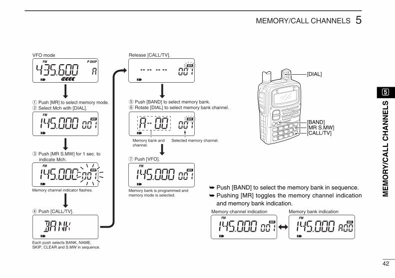
FM
FM
FM
FM
FM
q Push [MR] to select memory mode.w Select Mch with [DIAL].
e Push [MR S.MW] for 1 sec. to indicate Mch.
VFO mode
Memory channel indicator flashes.
Release [CALL/TV].
u Push [VFO].
Memory bank is programmed and memory mode is selected.
Memory bank indicationMemory channel indication
t Push [BAND] to select memory bank.y Rotate [DIAL] to select memory bank channel.
r Push [CALL/TV].
Each push selects BANK, NAME, SKIP, CLEAR and S.MW in sequence.
Memory bank and channel.
FM SKIPP
Selected memory channel.
[DIAL]
[BAND][MR S.MW][CALL/TV]
Push [BAND] to select the memory bank in sequence. Pushing [MR] toggles the memory channel indication
and memory bank indication.
tt
ME
MO
RY
/CA
LL
CH
AN
NE
LS

43
5 MEMORY/CALL CHANNELS
Memory clearUnwanted memory channels can be cleared (erased). Beforeclearing a memory channel make sure it is no longer neededas cleared memories cannot be recalled. Scan edges (0A/0B)cannot be cleared.
q Push [MR S.MW] for 1 sec. to indicate a memory channel.•Memory channel indicator blinks.•Do not hold [MR S.MW] for more than 2 sec., otherwise the pre-viously selected VFO or memory channel will be overwritten.
w Select the memory channel to be cleared with [DIAL].•Scan edges (0A/0B) cannot be cleared.
e Push [CALL/TV] several times to select “CLEAR.”
r Push [MR S.MW] for 1 sec. to clear the selected memorychannel.•3 beeps sound, then the frequency is cleared.
t Push [VFO] to return to the previous mode.
[DIAL]
[VFO]
[CALL/TV][MR S.MW]
AM SKIPP
VFO mode Memory mode
FM DUP T
44
5MEMORY/CALL CHANNELS
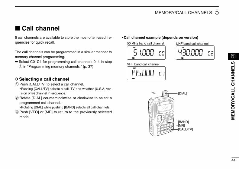
Call channel5 call channels are available to store the most-often-used fre-quencies for quick recall.
The call channels can be programmed in a similar manner tomemory channel programming.Select C0–C4 for programming call channels 0–4 in step
r in “Programming memory channels.” (p. 37)
DSelecting a call channelq Push [CALL/TV] to select a call channel.
•Pushing [CALL/TV] selects a call, TV and weather (U.S.A. ver-sion only) channel in sequence.
w Rotate [DIAL] counterclockwise or clockwise to select aprogrammed call channel.•Rotating [DIAL] while pushing [BAND] selects all call channels.
e Push [VFO] or [MR] to return to the previously selectedmode.
•Call channel example (depends on version)
[DIAL]
[BAND][MR][CALL/TV]
FM
FM FM
50 MHz band call channel UHF band call channel
VHF band call channel
tt
ME
MO
RY
/CA
LL
CH
AN
NE
LS

45
6 SCAN OPERATION
Scan types Up to 25 programmed scan ranges (0A/0B to 24A/24B), fullscan, band scan and memory bank scan provide scanningversatility. Each scan can have skip channels programmed.
DVFO scans
FULL SCAN (p. 46)Repeatedly scans all fre-quencies over the entire re-ceive range.•Some frequency ranges arerestricted depending onversions.
BAND SCAN (p. 46)Repeatedly scans all fre-quencies over the entire se-lected band.
PROGRAMMED SCAN (p. 46)Repeatedly scans betweentwo user-programmed fre-quencies. Used for checkingfor frequencies within aspecified range such as re-peater output frequencies,etc.
DMemory scans
FULL MEMORY SCAN (p. 48)Repeatedly scans all mem-ory channels except skipchannels.
SELECT BAND SCAN (p. 48)Repeatedly scans memorychannels except skip chan-nels within a selected mem-ory band. (e.g. WFM, 144Mor 440M memory band, etc.)
BANK SCAN (p. 48)Repeatedly scans memorychannels except skip chan-nels within specified memorybank (i.e. memory Bank,A00–A99).
CH-A00
CH-A01 CH-A03 CH-A04
CH-A12
CH-A13CH-A35CH-A99
SKIP
77.500
78.500 80.200 81.250
85.100
90.15096.500101.200
SKIP
(Unit: MHz)
CH-000
CH-001 CH-002 CH-003
CH-004
CH-005CH-006CH-499
SKIP
Jump
Lowerscan edge(0A–24A)
Upperscan edge(0B–24B)
Scan
Jump
Lowerband edge
Upperband edge
Scan
Jump
Start
Loweredge
Upperedge
Scan
Jump
P SKIPP SKIP

46
6SCAN OPERATION
yy
SC
AN
OP
ER
AT
ION
VFO scanThe following scans are available for the VFO scan.
FULL SCANRepeatedly scans all frequencies over the entire receiverange.•Some frequency ranges are restricted depending on versions.
BAND SCANRepeatedly scans all frequencies over the entire selectedband.
PROGRAMMED SCANRepeatedly scans between two user-programmed frequen-cies. Used for checking for frequencies within a specifiedrange such as repeater output frequencies, etc.
Skip frequencies are not scanned when the frequency skipfunction is in use. (“P SKIP” appears.)
If the same frequencies are programmed into a pair ofscan edges, programmed scan does not start.
For programmed scan, scan edges must be programmedin advance. Program scan edges in the same manner ofprogramming a memory channel. (p. 37)
q Select VFO mode with [VFO].w Push [5 SKIP] for 1 sec. to toggle the frequency skip func-
tion ON or OFF.• “P SKIP” appears when the frequency skip function is turned ON.
e Set the squelch level, if desired.r While pushing [MODE SCAN], rotate [DIAL] to select the
desired scan range.• “ALL” for full scan, “BAND” for band scan or “PROG 0–24” forprogrammed scan.
t Release [MODE SCAN] to start the scan.•Decimal point blinks while scanning.• “P SKIP” blinks when the frequency skip function is turned ON.•To change the scanning direction, rotate [DIAL].• If the pocket beep or DTCS beep function is activated, the trans-ceiver automatically selects the tone squelch or DTCS squelchfunction when a scan starts.
y To stop the scan, push [VFO].
FM SKIPP
Full scan Band scan
Programmed scan Scanning example
Flashes while scanning.

47
6 SCAN OPERATION
Frequency skip functionUnwanted frequencies can be skipped and programmed asskip channels when full scan, band scan or programmed scanis pausing.
q Start a VFO scan. (p. 46)w While receiving an unwanted signal and scan pauses,
push [5 SKIP] for 1 sec. to program the received frequencyas a skip frequency.•The transceiver emits 3 beeps and the scan resumes.•Non-programmed memory channels (blank channels) are usedfor skip frequency programming in reverse sequence.
•Do not release [5 SKIP] before 1 sec., otherwise, scan stops andthe transceiver enters frequency setting condition.
To scan the skip frequency after programming, cancel theskip information or clear the memory channel. (p. 43)
Skip channel settingMemory channels can be set to be skipped for memory skipscan. In addition, memory channels can be set to be skippedfor both memory skip scan and frequency skip scan. Theseare useful to speed up the scan interval.
q Select memory mode with [MR].w Rotate [DIAL] to select memory channel to set the skip in-
formation.e Push [5 SKIP] for 1 sec. one or more times to select con-
dition.• “OFF” for no skipping of channels, “SKIP” for memory skip scanor “P SKIP” for frequency skip scan and memory skip scan.
“P SKIP” setting is effective when the frequency skip func-tion is turned ON. (p. 46)
FM SKIPP
Skip indication
FM SKIPPFM SKIPP
Push [5 SKIP] for 1 sec. to programthe frequency as a skip frequency.
Blank channels are used in reverse sequence.
Flashes while scanning.
When scan pauses.

48
6SCAN OPERATION
yy
SC
AN
OP
ER
AT
ION
Memory scanMemory scan repeatedly scans all memory channels exceptskip channels.There are 3 types of memory scan, select band scan, fullbank scan and bank scan are available.
DFull memory scan/Select band scanq Push [MR] to enter memory mode.w While pushing and holding [MODE SCAN], rotate [DIAL] to
select from scan-guidance, [ALL], [SEL BC], [SEL 5], [SEL50], [SEL WFM], [SEL AIR], [SEL 144], [ SEL 220], [SEL300], [SEL 440] or [SEL 800].• [ALL] scans full programmed memories except skip channels.
•Scan-guidance appear(s) programmed band(s) only.
•Scan repeatedly scans memory channels except skip channels
within a selected memory band.
e Release [MODE SCAM] to start the memory scan.•Decimal point blinks while scanning.•To change the scanning direction, rotate [DIAL].•While receiving an unwanted signal and scan pauses, push [5SKIP] for 1 sec. to set the received channel as a skip channel.
r Push [VFO] to stop the scan.
DFull bank scan/Bank scanBank scan repeatedly scans memory channels except skipchannels within a selected memory bank.
q Push [MR] to enter the memory bank mode.•Pushing [MR] to toggles the memory channel and memory bankmodes.
•Program 2 or more memory channels to a memory bank in ad-vance.
w Push [BAND] several times to select the desired memorybank if desired.
e While pushing [MODE SCAN], rotate [DIAL] to select [ALL]or [BANK].• “ALL” scans for full bank or “BANK” scans for within a specifiedmemory bank only.
r Release [MODE SCAN] to start the memory scan.•Decimal point blinks while scanning.•To change the scanning direction, rotate [DIAL].
t Push [VFO] to stop the scan.
FM SKIPP
Release [MODE SCAN]Full bank scan
Select band scan
FM SKIPP
*Flashes while scanning.
FM SKIPP
Bank scan
*
*
* **
**Bank name appears.

49
6 SCAN OPERATION
Scan notesDSquelch settingScanning stops when the squelch opens. Make sure thesquelch is set to the threshold point or desired squelch level. Rotate the tuning dial while pushing [SQL] to select auto-
matic squelch (AUTO) or a level (1–9) where the noise ismuted. (p. 22)
DTuning dial while scanning Scan starts in the upward direction. To change the scan-
ning direction, rotate [DIAL] clockwise or counterclockwise. Rotating [DIAL] while pausing a scan resumes the scan
manually.
DTuning step while scanning Tuning steps while scanning becomes the selected tuningstep. Reset the tuning step before scanning, if necessary. (p. 18)
DSkip functionMemory channels can be set to be skipped for memory skipscan. In addition, memory channels can be set to be skippedfor both memory skip scan and frequency skip scan. Theseare useful to speed up the scan interval. (p. 47)
DWhen receiving a signalThe scan pauses according to the scan pause time (default:10 sec.). It can be selected as a pause or timer scan (2–20 sec.) in set mode. (p. 58)
The scan restarts after a signal disappears according to theresume time (default: 2 sec.). It can be selected to 0–5 sec. or‘hold’ (indefinitely) in set mode. (p. 58)
DScan stop beepA beep sounds when a scan stops to confirm the scan de-tects a signal. This function can be turned ON or OFF in ex-panded set mode 1. (p. 62)
DScan stop LEDThe keypad backlighting blinks when a scan stops to confirmthe scan detects a signal. This function can be turned ON orOFF in expanded set mode 1. (p. 62)
DBusy LED ON/OFFThe receive indicator can be turned ON or OFF in set mode.(p. 59)

50
7PRIORITY WATCH
Priority watch typesPriority watch checks for signals on a frequency every 5 sec.while operating on a VFO frequency or scanning. The trans-ceiver has 6 priority watch types to suit your needs.
The watch resumes according to the selected scan resumecondition. See p. 58 for details.
MEMORY or CALL CHANNEL WATCHWhile operating on a VFO frequency, priority watch checksfor a signal in the selected memory or call channel every 5sec.•A memory channel with skip information can be watched.
MEMORY SCAN WATCHWhile operating on a VFO frequency, priority watch checksfor signals in each memory channel in sequence.•The memory skip function is useful to speed up the scan.
VFO SCAN with MEMORY or CALL CHANNEL WATCHWhile scanning in VFO mode, priority watch checks for sig-nals in the selected memory or call channel every 5 sec.
VFO SCAN with MEMORY SCAN WATCHWhile scanning in VFO mode, priority watch checks for sig-nals in memory channels every 5 sec.
If the pocket beep function is activated, the transceiver au-tomatically selects the tone squelch function when prioritywatch starts.
Priority alertYou can be alerted with beeps and a blinking “S,” when apriority watch detects a signal on the watching frequency.
q Push [8 SET] for 1 sec. to enter set mode.w Rotate [DIAL] until “PRIO” appears.
e Push [8 SET] to select the priority watch item.r Rotate [DIAL] to select the priority alert item. (“BELL”)
t Push [VFO] to exit set mode and start the priority watch.
uu
PR
IOR
ITY
WA
TC
H

51
7 PRIORITY WATCH
Priority watch operationDMemory channel watchWhile operating on a VFO frequency, priority watch checksfor a signal in the selected memory channel every 5 sec.•A memory channel with skip information can be watched.
q Select VFO mode; then, set an operating frequency.w Select the desired memory channel.e Push [8 SET] for 1 sec. to enter set mode.r Rotate [DIAL] until “PRIO” appears.t Push [8 SET] to select the priority watch item.y Rotate [DIAL] to select the priority watch (“ON”) or priority
watch with alert (“BELL”).
u Push [VFO] to exit set mode and start the priority watch.•The transceiver checks the memory channel frequency every 5 sec.
•The watch resumes according to the selected scan resume con-dition. (p. 58)
i Push [VFO] while the display shows the VFO frequency tostop the watch.
PRIOFM
PRIOFM SKIPP
Checks for a signal in the selected memory channel every 5 sec.
While operating on a VFO frequency
The watch stops on the selectedchannel when a signal is received.
FMPRIO
SKIPP
[VFO]
[DIAL]
[8 SET]
Priority watch item
Priority watch with alert
Push [VFO] to start.
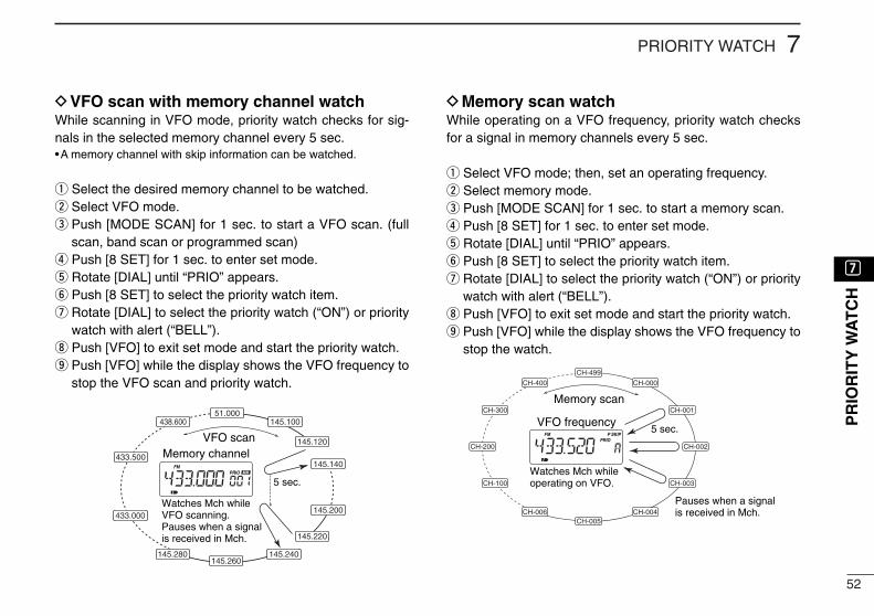
52
7PRIORITY WATCH
DVFO scan with memory channel watchWhile scanning in VFO mode, priority watch checks for sig-nals in the selected memory channel every 5 sec.•A memory channel with skip information can be watched.
q Select the desired memory channel to be watched.w Select VFO mode.e Push [MODE SCAN] for 1 sec. to start a VFO scan. (full
scan, band scan or programmed scan)r Push [8 SET] for 1 sec. to enter set mode.t Rotate [DIAL] until “PRIO” appears.y Push [8 SET] to select the priority watch item.u Rotate [DIAL] to select the priority watch (“ON”) or priority
watch with alert (“BELL”).i Push [VFO] to exit set mode and start the priority watch.o Push [VFO] while the display shows the VFO frequency to
stop the VFO scan and priority watch.
DMemory scan watchWhile operating on a VFO frequency, priority watch checksfor a signal in memory channels every 5 sec.
q Select VFO mode; then, set an operating frequency.w Select memory mode.e Push [MODE SCAN] for 1 sec. to start a memory scan.r Push [8 SET] for 1 sec. to enter set mode.t Rotate [DIAL] until “PRIO” appears.y Push [8 SET] to select the priority watch item.u Rotate [DIAL] to select the priority watch (“ON”) or priority
watch with alert (“BELL”).i Push [VFO] to exit set mode and start the priority watch.o Push [VFO] while the display shows the VFO frequency to
stop the watch.
CH-000
CH-499
CH-400
CH-300
CH-200
CH-100
CH-006CH-005
CH-004
CH-003
CH-002
CH-001Memory scan
VFO frequency5 sec.
Pauses when a signal is received in Mch.
Watches Mch while operating on VFO.
FM SKIPPPRIOVFO scan
Memory channel
5 sec.
Watches Mch while VFO scanning.Pauses when a signal is received in Mch.
FMPRIO
145.100
145.120
145.140
145.200
145.220
145.240145.260
51.000438.600
433.500
433.000
145.280
uu
PR
IOR
ITY
WA
TC
H
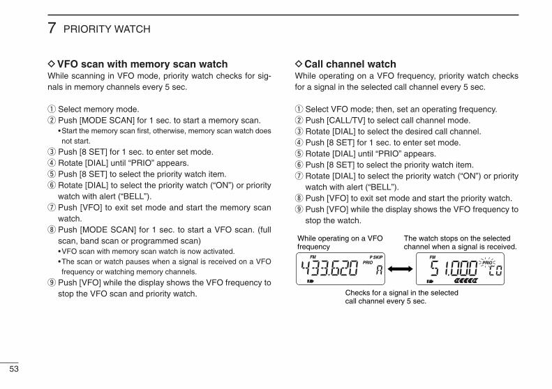
53
7 PRIORITY WATCH
DVFO scan with memory scan watchWhile scanning in VFO mode, priority watch checks for sig-nals in memory channels every 5 sec.
q Select memory mode.w Push [MODE SCAN] for 1 sec. to start a memory scan.
•Start the memory scan first, otherwise, memory scan watch doesnot start.
e Push [8 SET] for 1 sec. to enter set mode.r Rotate [DIAL] until “PRIO” appears.t Push [8 SET] to select the priority watch item.y Rotate [DIAL] to select the priority watch (“ON”) or priority
watch with alert (“BELL”).u Push [VFO] to exit set mode and start the memory scan
watch.i Push [MODE SCAN] for 1 sec. to start a VFO scan. (full
scan, band scan or programmed scan)•VFO scan with memory scan watch is now activated.•The scan or watch pauses when a signal is received on a VFOfrequency or watching memory channels.
o Push [VFO] while the display shows the VFO frequency tostop the VFO scan and priority watch.
DCall channel watchWhile operating on a VFO frequency, priority watch checksfor a signal in the selected call channel every 5 sec.
q Select VFO mode; then, set an operating frequency.w Push [CALL/TV] to select call channel mode.e Rotate [DIAL] to select the desired call channel.r Push [8 SET] for 1 sec. to enter set mode.t Rotate [DIAL] until “PRIO” appears.y Push [8 SET] to select the priority watch item.u Rotate [DIAL] to select the priority watch (“ON”) or priority
watch with alert (“BELL”).i Push [VFO] to exit set mode and start the priority watch.o Push [VFO] while the display shows the VFO frequency to
stop the watch.
FMPRIO
SKIPP FMPRIO
Checks for a signal in the selected call channel every 5 sec.
While operating on a VFO frequency
The watch stops on the selectedchannel when a signal is received.

54
7PRIORITY WATCH
DVFO scan with call channel watchWhile scanning in VFO mode, priority watch checks for sig-nals in the selected call channel every 5 sec.
q Select VFO mode.w Push [CALL/TV] to select call channel mode.e Rotate [DIAL] to select the desired call channel.r Push [8 SET] for 1 sec. to enter set mode.t Rotate [DIAL] until “PRIO” appears.y Push [8 SET] to select the priority watch item.u Rotate [DIAL] to select the priority watch (“ON”) or priority
watch with alert (“BELL”).i Push [VFO] to exit set mode and start the priority watch.o Push [MODE SCAN] for 1 sec. to start a VFO scan. (full
scan, band scan or programmed scan)!0 Push [VFO] while the display shows the VFO frequency to
stop the VFO scan and priority watch.
VFO scanCall channel
5 sec.
Watches call Ch while VFO scanning.Pauses when a signal is received in call Ch.
PRIOFM
145.100
145.120
145.140
145.200
145.220
145.240145.260
51.000850.000*
433.500
433.000
145.280
*UK and Italy versions only.
uu
PR
IOR
ITY
WA
TC
H

55
8 SET MODE
Set modeSet mode is used for programming in-frequently changed values or conditionsof functions.
In addition, this transceiver has 2 ex-panded set modes which are used forprogramming more infrequentlychanged values or conditions of func-tions. When turning the expanded setmodes OFF, only half of the set modeitems are displayed for simple opera-tion.
DEntering set modeq Push [8 SET] for 1 sec. to enter set
mode.w Rotate [DIAL] until the desired item
appears.
e Push [8 SET] to select the set modeitem.
r Rotate [DIAL] to select a set modeitem.
t Push [VFO] to exit set mode or push[8 SET] then rotate [DIAL] to selectanother set mode item.
DExpanded set mode ON/OFFq Push [8 SET] for 1 sec. to enter set
mode.w Rotate [DIAL] until “EXP1” or “EXP2”
appears.
e Push [8 SET] to select an expandedset mode.
r Rotate [DIAL] to turn the expandedset mode ON or OFF.
t Push [8 SET] then rotate [DIAL] toselect a set mode item in the ex-panded set mode, or push [VFO] toexit set mode.
SKIPPFM
[VFO]
[8 SET]
[DIAL]

56
8SET MODE
Set mode itemsSet mode is used for programming infrequently changed val-ues or conditions of functions.
General set mode R TONE Repeater tone (p. 57)C TONE Tone squelch/pocket beep frequency (p. 57)CODE DTCS squelch code (p. 57)OFFSET Offset frequency (p. 57)RESUME Scan resume time (p. 58)PAUSE Scan pause timer (p. 58)PRIO Priority watch (p. 58)BEEPLV Beep tone level (p. 58)BEEP Beep tone (p. 59)LIGHT Display backlighting (p. 59)BUSY Busy LED (p. 59)AP OFF Auto power OFF (p. 59)P SAVE Power save (p. 60)MONI Monitor switch action (p. 60)SPEED Dial speed acceleration (p. 60)DTMF DTMF speed (p. 61)MIC Optional HM-75A functions (p. 61)EXP1 Expanded set mode 1 (upper right)EXP2 Expanded set mode 2 (lower right)
EXP1 (Expanded set mode 1)STOP B Scan stop beep (p. 62)STOP L Scan stop LED (p. 62)LIGHTP Backlighting position (p. 62)COLOR Backlighting color (p. 63)EDGE B Band edge beep (p. 63)AP ON Auto power ON (p. 63)LOCK Key lock effect (p. 63)PTT LK PTT lock (p. 64)CONT LCD contrast (p. 64)OPN.MSG Opening message (p. 64)
Appears when expanded set mode 1 is ON.
EXP2 (Expanded set mode 2)DTCS P DTCS phase mode (p. 65)LK OUT Busy lockout (p. 65)TOT Time-out timer (p. 65)ACTIVE Active band (p. 65)SPLIT Split operation (p. 66)NARROW FM narrow deviation (p. 66)MC SYN Morse code synthesizer (p. 66)KY SPD Morse code keying speed (p. 66)
Appears when expanded set mode 2 is ON.
ii
SE
T M
OD
E

57
8 SET MODE
•Repeater tone (R TONE)Selects tone encoder frequency for accessing a repeater, etc.from one of 50 available tone frequencies.
•67.0–254.1 Hz (50 tones):88.5 Hz (default)
•Tone squelch/pocket beep frequency (C TONE)Selects tone squelch or pocket beep frequency from one of50 available tone frequencies.
•67.0–254.1 Hz (50 tones):88.5 Hz (default)
[Repeater/Tone squelch tone table]
•DTCS squelch code (CODE)Selects DTCS squelch code from one of 104 available codes.•023–754 (104 codes):
023 (default)
[DTCS code table]
•Offset frequency (OFFSET)Sets the offset frequency for duplex(repeater) operation within0–159.995 MHz range.
The offset frequency changesaccording to the selected tuningsteps. (p. 18)
023025026031032036043047051053054065
071072073074114115116122125131132134
143145152155156162165172174205212223
225226243244245246251252255261263265
266271274306311315325331332343346351
356364365371411412413423431432445446
452454455462464465466503506516523526
532546565606612624627631632654662664
703712723731732734743754
67.069.371.974.477.079.7
82.585.488.591.594.897.4
100.0103.5107.2110.9114.8118.8
123.0127.3131.8136.5141.3146.2
151.4156.7159.8162.2165.5167.9
171.3173.8177.3179.9183.5186.2
189.9192.8196.6199.5203.5206.5
210.7218.1225.7229.1233.6241.8
250.3254.1

58
8SET MODE
•Scan resume time (RESUME)Selects the scan resume time from pausing on a frequencyafter the received signal disappears.
•0 scan resumes when a receivedsignal disappears.
•1–5 scan pauses 1–5 sec. after areceived signal disappears.(default: 2 sec.)
•Hold scan pauses on a received sig-nal even if it disappears. Rotatethe tuning dial to resume manu-ally.
•Scan pause timer (PAUSE)Selects the scan pause time. When receiving signals, thescan pauses according to the scan pause time.
•2–20 scan pauses for 2–20 sec. ona received signal in 2 sec.steps. (default: 10 sec.)
•Hold scan pauses on a receivedsignal until it disappears. Ro-tate the tuning dial to resumemanually.
•Priority watch (PRIO)Activates priority watch or priority watch with alert (BELL).
•OFF The priority watch isturned OFF. (default)
•ON The transceiver checksthe memory channel fre-quency every 5 sec.
•BELL The transceiver checksthe memory channel fre-quency every 5 sec. Youcan be alerted with beepsand a blinking “S.”
•Beep tone level (BEEPLV)Adjusts confirmation beep output level to the desired levelwithin 32 levels or to the related level with volume.
The confirmation beep (next item) must be turned on tohave a beep tone.
•VOLUME The beep tone volumelevel is linked with thereceive volume level.(default)
• - - - - - - The beep tone volumeooo ooo level can be set in 32
steps.
ii
SE
T M
OD
E

59
8 SET MODE
•Beep tone (BEEP)Turns confirmation beep ON or OFF.
•ON The confirmation beep is turnedON. (default)
•OFF The confirmation beep is turnedOFF.
•Display backlighting (LIGHT)The transceiver has display backlighting with a 5 sec. timerfor nighttime operation. The display backlighting can beturned ON continuously or turned OFF, if desired.
“AUTO” setting turns the backlight-ing ON while operating with an ex-ternal DC power. (10–11.5 V DC)
•AUTO The display backlighting isON with a 5 sec. timer. (de-fault)
•ON The display backlighting is turned ON.•OFF The display backlighting is turned OFF.
•Busy LED (BUSY)The TX/RX indicator lights green while receiving a signal orwhen the squelch is open. This indication can be turned OFFto conserve the battery power, if desired.
•ON The indicator lights greenwhile receiving a signal orwhen the squelch is open.(default)
•OFF The indicator does not func-tion even if a signal is re-ceived.
•Auto power OFF (AP OFF)The transceiver can be set to automatically turn OFF after aspecified period with beep in which no switch is pushed.
120 min., 90 min., 60 min., 30 min.and OFF can be specified. Thespecified period is retained evenwhen the transceiver is turned OFFby the auto power-off function. Tocancel the function, select “OFF” inthis set mode.

60
8SET MODE
•Power save (P SAVE)The power save function reduces the current drain to con-serve battery power. This item sets the power save dutycycle—the ratio of receive circuit on to receive circuit off whilestanding by. The duty cycle can be set to automatic (default),1:1, 1:4, 1:8, 1:16 or OFF.
“AUTO” selects “1:4” duty ratio when receiving no signal for 5sec., then “1:8” 60 sec. after that.
When “AUTO” is selected, the power save automaticallyturns OFF while operating with an external DC power.(10–11.5 V DC)
For packet operation, the power save should be turnedOFF to receive reliable packet data.
•Monitor switch action (MONI)The monitor switch can be set as a ‘sticky’ switch. When setto the sticky condition, each push of [SQL] toggles the moni-tor function on and off.
•PUSH Set the monitor switch tonormal. (default)
•HOLD Set the monitor switch tosticky switch.
•Dial speed acceleration (SPEED)The dial speed acceleration automatically speeds up the tun-ing dial speed when rotating the [DIAL] rapidly.
•ON The dial speed accelerationis turned ON. (default)
•OFF The dial speed accelerationis turned OFF.
ii
SE
T M
OD
E

•DTMF speed (DTMF)The rate at which DTMF memories send individual DTMFcharacters can be set to accommodate operating needs.
DISPLAY INTERVAL SPEED100 100 msec. 5.0 cps200 200 msec. 2.5 cps300 300 msec. 1.6 cps500 500 msec. 1.0 cps
cps=characters/sec.
•Optional HM-75A functions (MIC)Microphone simple mode is used to change the function as-signments for switches on the optional HM-75A REMOTE CON-
TROL MICROPHONE.
•NORM-1: (default)
[A] Selects band.[B] Toggles VFO and memory.[Y] [UP][Z] [DOWN]
•NORM-2: [A] Toggles monitor function.[B] Toggles VFO and memory.[Y] [UP][Z] [DOWN]
•SIMPLE: [A] Toggles monitor function.[B] Selects call channel C0.[Y] Selects memory Ch 000.[Z] Selects memory Ch 001.
VFO mode cannot be selected via the microphone whenSIMPLE mode is selected.
61
8 SET MODE

62
8SET MODE
•Scan stop beep (STOPB)Turns scan stop beep ON or OFF.•Turn the expanded set mode 1 ON in advance.
•ON The scan stop beep soundswhen a scan is stopped.
•OFF The scan stop beep does notsound even when a scan isstopped. (default)
•Scan stop LED (STOP L)Turns scan stop LED ON or OFF.•Turn the expanded set mode 1 ON in advance.
•ON The keypad backlightingblinks in green and orangewhen a scan is stopped.
•OFF The keypad backlightingdoes not blink even when ascan is stopped. (default)
•Backlighting position (LIGHTP)Selects the lighting area from keypad only, function displayonly and both keypad and function display.•Turn the expanded set mode 1 ON in advance.
•ALL Lighting area is both keypadand function display. (de-fault)
•KEY Lighting area is keypad only.•LCD Lighting area is function dis-
play only.
ii
SE
T M
OD
E

63
8 SET MODE
•Backlighting color (COLOR)Selects backlighting color between green, orange or red.•Turn the expanded set mode 1 ON in advance.
•GREEN Green backlighting color.(default)
•ORANGE Orange backlighting color. •RED Red backlighting color.
•Band edge beep (EDGE B)Turns band edge beep ON or OFF. The band edge beepsounds when the operating frequency changes across theband edge.•Turn the expanded set mode 1 ON in advance.
•ON The band edge beep is turnedON.
•OFF The band edge beep is turnedOFF. (default)
•Auto power ON (AP ON)Turns the transceiver power ON after 30 min. to 24 hrs. in 30min. steps.•Turn the expanded set mode 1 ON in advance.
When operating with batterypack or case and the battery isexhausted, auto power-on doesnot function.
•Key lock effect (LOCK)While the lock function is ON, [PWR], [PTT], [SQL], [Y]/[Z]and [CALL/TV LOCK] can still be accessed. Accessibleswitches can be set to 1 of 4 groups.•Turn the expanded set mode 1 ON in advance.
•NORMAL [PWR], [PTT], [SQL]and [Y]/[Z] are acces-sible.
•NO SQL [PWR], [PTT] and[SQL] are accessible.
•NO VOL [PWR], [PTT] and[Y]/[Z] are accessible.
•ALL [PWR] and [PTT] are accessible.

64
8SET MODE
•PTT lock (PTT LK)Turns PTT lock ON or OFF.•Turn the expanded set mode 1 ON in advance.
•ON The PTT lock is turned ON. •OFF The PTT lock is turned OFF.
(default)
•LCD contrast (CONT)The contrast of the LCD can be adjusted from 4 levels. •Turn the expanded set mode 1 ON in advance.
•1 (low contrast) – 4 (high contrast)3 (default)
•Opening message (OPN.MSG)Turns opening message ON or OFF.•Turn the expanded set mode 1 ON in advance.
•ON Displays the opening mes-sage at power ON. (default)
•OFF Does not display the open-ing message at power ON.
ii
SE
T M
OD
E

65
8 SET MODE
•DTCS phase mode (DTCS P)Selects DTCS phase mode.•Turn the expanded set mode 2 ON in advance.
•BOTH N Normal phases are used forboth Tx and Rx. (default)
•TN-RR Normal phase is used forTx; Reverse phase for Rx.
•TR-RN Reverse phase is used forTx; Normal phase for Rx.
•BOTH R Reverse phases are usedfor both Tx and Rx.
•Busy lockout (LK OUT)Turns the busy lockout function ON and OFF. This functioninhibits transmission while receiving a signal or when thesquelch is open.•Turn the expanded set mode 2 ON in advance.
•ON The busy lockout is turned ON. •OFF The busy lockout is turned
OFF. (default)
•Time-out timer (TOT)To prevent accidental prolonged transmission, etc., the trans-ceiver has a time-out timer. This timer cuts a transmissionOFF after 1, 3, 5 or 10 min. of continuous transmission. Thistimer can be cancelled.•Turn the expanded set mode 2 ON in advance.
Approx. 10 sec. before the time-out timer is activated, thetransceiver emits a beep tone as a warning.
•OFF The time-out timer is turnedOFF. (default)
•1–10 The transmission is cut OFFafter the set period elapses.
•Active band (ACTIVE)Allows continuous frequency selection of the operating fre-quency across all bands.
•ALL The operating frequencycan be selected continu-ously. (default)
•SINGLE The operating frequencycan be selected withinthe current band. Push[BAND] for band selec-tion in this case.

66
8SET MODE
•Split operation (SPLIT)Turns the split operation ON or OFF. Split frequency opera-tion allows you to transmit and receive on two different fre-quencies. Split frequency operation uses 2 frequencies, onein VFO A and the other in VFO B.•Turn the expanded set mode 2 ON in advance.
•ON The split operation is turnedON. ‘SPA’ appears for VFO A;‘SPB’ appears for VFO B.
•OFF The split operation is turnedOFF. (default)
•FM narrow deviation (NARROW)Selects the maximum FM deviation for normal or narrow ontransmit mode.
•ON Selects the narrow FM devia-tion.
•OFF Selects the normal FM devia-tion. (default)
•Morse code synthesizer (MC SYN)The transceiver announces the operating frequency or TVchannel number in Morse code.•Turn the expanded set mode 2 ON in advance.
•ON The Morse code synthesizeris turned ON.
•OFF The Morse code synthesizeris turned OFF. (default)
Turning power ON while pushing[CALL/TV] also toggles theMorse code synthesizer ON or OFF.
•Morse code keying speed (KY SPD)The keying speed of the Morse code synthesizer can be ad-justed within 10 to 25 WPM for your convenience. •Turn the expanded set mode 2 ON in advance.
•10–25 WPM in 5 WPM steps20 WPM (default)
ii
SE
T M
OD
E
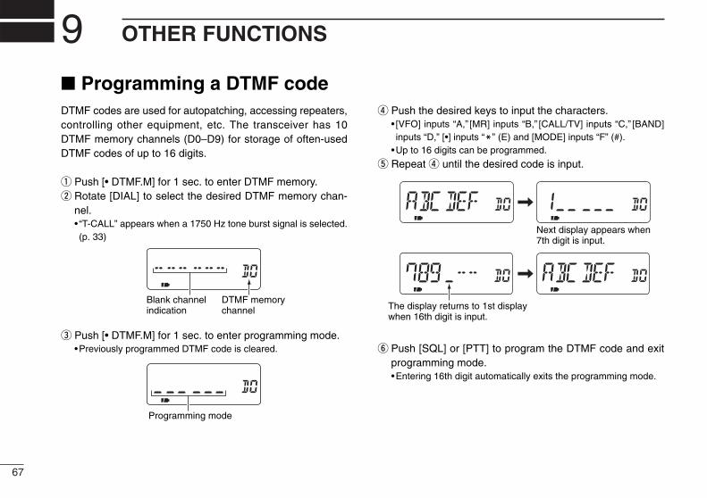
67
9 OTHER FUNCTIONS
Programming a DTMF codeDTMF codes are used for autopatching, accessing repeaters,controlling other equipment, etc. The transceiver has 10DTMF memory channels (D0–D9) for storage of often-usedDTMF codes of up to 16 digits.
q Push [• DTMF.M] for 1 sec. to enter DTMF memory.w Rotate [DIAL] to select the desired DTMF memory chan-
nel.• “T-CALL” appears when a 1750 Hz tone burst signal is selected.(p. 33)
e Push [• DTMF.M] for 1 sec. to enter programming mode.•Previously programmed DTMF code is cleared.
r Push the desired keys to input the characters.• [VFO] inputs “A,” [MR] inputs “B,” [CALL/TV] inputs “C,” [BAND]inputs “D,” [•] inputs “M” (E) and [MODE] inputs “F” (#).
•Up to 16 digits can be programmed.
t Repeat r until the desired code is input.
y Push [SQL] or [PTT] to program the DTMF code and exitprogramming mode.•Entering 16th digit automatically exits the programming mode.
Next display appears when 7th digit is input.
The display returns to 1st display when 16th digit is input.
Programming mode
DTMF memorychannel
Blank channelindication

68
9OTHER FUNCTIONS
Transmitting a DTMF codeDTransmitting from DTMF memoryThe selected DTMF code is transmitted at each push of the[SQL] switch while transmitting.
The rate at which DTMF memories send individual DTMFcharacters can be set in set mode. (p. 61)
q Set the desired frequency.w Push [• DTMF.M] for 1 sec. to enter DTMF memory.e Rotate [DIAL] to select the desired DTMF memory chan-
nel.r Push [VFO] to exit DTMF memory.t While pushing [PTT], push [SQL] to transmit the selected
DTMF code.
DTransmitting a DTMF code directlyDTMF code can be transmitted via keypad directly whiletransmitting.
q Set the desired frequency.w While pushing [PTT], push the desired keys to transmit the
DTMF code.• [VFO] transmits “A,” [MR] transmits “B,” [CALL/TV] transmits “C,”[BAND] transmits “D,” [•] transmits “E” (M) and [MODE] transmits“F” (#).
FM SKIPP
[PTT]
DTMF code is not displayed.
[SQL]
[PTT]
[• DTMF.M]
[DIAL]
[VFO]
DTMF code is displayed6 digits at a time.
oo
OT
HE
R F
UN
CT
ION
S

69
9 OTHER FUNCTIONS
Clearing a DTMF memoryAn unwanted DTMF memory can be cleared (erased).
q Push [• DTMF.M] for 1 sec. to enter DTMF memory mode.w Rotate [DIAL] to select the desired DTMF memory chan-
nel to be cleared.e Push [• DTMF.M] for 1 sec. to enter programming mode
and clear the selected DTMF memory channel.•The DTMF memory channel is cleared.
r Push [SQL] or [PTT] to exit programming mode.
Confirming a DTMF memoryThe DTMF memory can be confirmed with DTMF tone.
q Push [• DTMF.M] for 1 sec. to enter DTMF memory mode.w Rotate [DIAL] to select the desired DTMF memory chan-
nel.e Push [SQL] to confirm the DTMF memory contents.
•The display returns to frequency indication after confirmation.
FM SKIPP
[SQL]
[• DTMF.M]
[DIAL]DTMF code is displayed6 digits at a time.
The display returns tofrequency indication.
[SQL]
[PTT]
[• DTMF.M]
[DIAL]
[VFO]
Select DTMF memory to be cleared.
DTMF programming mode
The DTMF memory becomes blank.

70
9OTHER FUNCTIONS
•Subaudible (repeater) toneSome repeaters require subaudibletones to be accessed. Subaudibletones are superimposed over your nor-mal signal and must be set in advance.
•Tone and DTCS squelchesThe tone squelch (CTCSS) or DTCSsquelch opens only when receiving asignal containing a matching subaudi-ble tone or DTCS code, respectively.You can silently wait for calls fromgroup members using the same tone orcode. Separate tone frequencies canbe set for repeater and tonesquelch/pocket beep operation.
•Pocket and DTCS beepThese functions use subaudible tonesor DTCS code for calling and can beused as a “common pager” to informyou that someone has called while youwere away from the transceiver. Samecode is used for DTCS squelch andbeep.
DSetting subaudible tones forrepeater or tone squelch
q Push [8 SET] for 1 sec. to enter setmode.
w Rotate [DIAL] until “R TONE” (re-peater tone) or “C TONE” (CTCSStone) appears.
e Push [8 SET].r Rotate [DIAL] to select the desired
repeater or CTCSS tone.•Each operating band and each memorychannel have independent settings.
t Push [VFO] to exit set mode.
DSetting DTCS code forDTCS squelch or beep
q Push [8 SET] for 1 sec. to enter setmode.
w Rotate [DIAL] until “CODE” appears.
e Push [8 SET].r Rotate [DIAL] to select the desired
DTCS code.•Each operating band and each memorychannel have independent settings.
t Push [VFO] to exit set mode.
DTCS phase mode can be selectedin expanded set mode 2. (p. 65)
Tone frequency and DTCS code
oo
OT
HE
R F
UN
CT
ION
S

71
9 OTHER FUNCTIONS
Tone/DTCS squelchq Set the desired operating frequency, CTCSS tone and
DTCS code.w Push [2 TONE] for 1 sec. one or more times to activate the
tone or DTCS squelch. (T SQL or DTCS)•Subaudible tone encoder “T,” tone squelch “T SQL,” pocket beep“T SQLS,” DTCS squelch “DTCS,” DTCS beep “SDTCS”and no tone operation are activated in order.
•Rotating [DIAL] while pushing [2 TONE] also selects the tonefunctions.
e Operate the transceiver in the normal way.r When the received signal includes a matching tone,
squelch opens and the signal can be heard.•When the received signal’s tone does not match, tone squelchdoes not open, however, the S-indicator shows signal strength.
•To open the squelch manually, push and hold [SQL].
Pocket beep functionq Set the desired operating frequency.w Set the desired CTCSS tone or DTCS code.e Push [2 TONE] for 1 sec. one or more times to activate the
pocket beep or DTCS beep. (T SQLS or SDTCS)•Rotating [DIAL] while pushing [2 TONE] also selects the tonefunctions.
r When a signal with the correct tone or code is received,the transceiver emits beep tones for 30 sec. and blinks“S”.
t Push [PTT] to answer or push [SQL] to stop the beeps andblinking.
CONVENIENTStore subaudible tone frequencies, DTCS code, DTCS phasemode and tone/DTCS squelch ON/OFF settings in memories(call) for easy recall.
FM DTCS SKIPP
FM SQL SKIPT PPocket beepby CTCSS dode
Pocket beepby DTCS code
FM SKIPP
FM SKIPT P
FM SQL SKIPT P
FM SQL SKIPT P
FM DTCS SKIPP
FM DTCS SKIPP
No tone operation
Subaudible tone encoder
Tone squelch
Pocket beep
DTCS beep
DTCS squelch

72
9OTHER FUNCTIONS
Available tone frequenciesThe transceiver has 50 tone frequencies for repeater andtone squelch (CTCSS)/pocket beep operation. Separate tonefrequencies can be set for repeater and tone squelch/pocketbeep operation.
(unit: Hz)
The transceiver has 50 tone frequencies and consequentlytheir spacing is narrow compared with units having 38tones. Therefore, some tone frequencies may receive in-terference from adjacent tone frequencies.
Available DTCS codesThe transceiver has 104 DTCS codes for DTCS squelch andDTCS beep.
67.069.371.974.477.079.7
82.585.488.591.594.897.4
100.0103.5107.2110.9114.8118.8
123.0127.3131.8136.5141.3146.2
151.4156.7159.8162.2165.5167.9
171.3173.8177.3179.9183.5186.2
189.9192.8196.6199.5203.5206.5
210.7218.1225.7229.1233.6241.8
250.3254.1
023025026031032036043047051053054065
071072073074114115116122125131132134
143145152155156162165172174205212223
225226243244245246251252255261263265
266271274306311315325331332343346351
356364365371411412413423431432445446
452454455462464465466503506516523526
532546565606612624627631632654662664
703712723731732734743754
oo
OT
HE
R F
UN
CT
ION
S
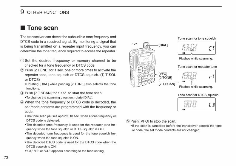
73
9 OTHER FUNCTIONS
Tone scanThe transceiver can detect the subaudible tone frequency andDTCS code in a received signal. By monitoring a signal thatis being transmitted on a repeater input frequency, you candetermine the tone frequency required to access the repeater.
q Set the desired frequency or memory channel to bechecked for a tone frequency or DTCS code.
w Push [2 TONE] for 1 sec. one or more times to activate therepeater tone, tone squelch or DTCS squelch. (T, T SQLor DTCS)•Rotating [DIAL] while pushing [2 TONE] also selects the tonefunctions.
e Push [7 T.SCAN] for 1 sec. to start the tone scan.•To change the scanning direction, rotate [DIAL].
r When the tone frequency or DTCS code is decoded, theset mode contents are programmed with the frequency orcode.•The tone scan pauses approx. 10 sec. when a tone frequency orDTCS code is detected.
•The decoded tone frequency is used for the repeater tone fre-quency when the tone squelch or DTCS squelch is OFF.
•The decoded tone frequency is used for the tone squelch fre-quency when the tone squelch is ON.
•The decoded DTCS code is used for the DTCS code when theDTCS squelch is ON.
• “CT,” “rT” or “CD” appears according to the tone setting.
t Push [VFO] to stop the scan.• If the scan is cancelled before the transceiver detects the toneor code, the set mode contents are not changed.
[DIAL]
[VFO][2 TONE]
[7 T.SCAN]
Tone scan for tone squelch
Tone scan for repeater tone
Tone scan for DTCS squelch
Flashes while scanning.
Flashes while scanning.

74
9OTHER FUNCTIONS
Beep tonesYou can select to have confirmation beeps sound at the pushof a switch. The output level can be adjusted within 32 levelsor to the related level of the volume. (p. 58)
You can select silent operation by turning beep tones OFF.(p. 59)
These can be selected in set mode.
Dial speed accelerationThe dial speed acceleration automatically speeds up the tun-ing dial speed when rotating the [DIAL] rapidly.
This function can be turned ON and OFF in set mode. (p. 60)
Lock functionThe lock function prevents accidental frequency changes andaccidental function access.
Push [CALL/TV LOCK] for 1 sec. to toggle the lock functionON and OFF.• [PWR], [VOL], [SQL] and [PTT] can still be accessed while thelock function is ON. (default)
DKey lock effectWhile the lock function is ON, [PWR], [VOL], [SQL] and [PTT]can still be accessed. Accessible switches can be set to 1 of 4groups in expanded set mode 1. (p. 63)
• “NORMAL” : [PWR], [VOL], [SQL] and [PTT] are accessible.• “NO SQL” : [PWR], [SQL] and [PTT] are accessible.• “NO VOL” : [PWR], [VOL] and [PTT] are accessible.• “ALL” : [PWR] and [PTT] are accessible.
FM SKIPP
Lock indication
oo
OT
HE
R F
UN
CT
ION
S
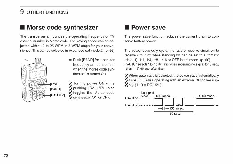
75
9 OTHER FUNCTIONS
Morse code synthesizerThe transceiver announces the operating frequency or TVchannel number in Morse code. The keying speed can be ad-justed within 10 to 25 WPM in 5 WPM steps for your conve-nience. This can be selected in expanded set mode 2. (p. 66)
Push [BAND] for 1 sec. forfrequency announcementwhen the Morse code syn-thesizer is turned ON.
Turning power ON whilepushing [CALL/TV] alsotoggles the Morse codesynthesizer ON or OFF.
Power saveThe power save function reduces the current drain to con-serve battery power.
The power save duty cycle, the ratio of receive circuit on toreceive circuit off while standing by, can be set to automatic(default), 1:1, 1:4, 1:8, 1:16 or OFF in set mode. (p. 60)• “AUTO” selects “1:4” duty ratio when receiving no signal for 5 sec.,then “1:8” 60 sec. after that.
When automatic is selected, the power save automaticallyturns OFF while operating with an external DC power sup-ply. (11.0 V DC ±5%)
Circuit on
Circuit off150 msec.
60 sec.
600 msec. 1200 msec.No signal5 sec.
[PWR]
[BAND]
[CALL/TV]

76
9OTHER FUNCTIONS
Time-out timerTo prevent accidental prolonged transmission, etc., the trans-ceiver has a time-out timer. This timer cuts a transmissionOFF after 1, 3, 5 or 10 min. of continuous transmission. Thistimer can be cancelled (default).
Approx. 10 sec. before the time-out timer is activated, thetransceiver emits a beep tone as a warning.
This can be selected in expanded set mode 2. (p. 65)
PTT lockTo prevent accidental transmission, etc., the transceiver has aPTT lock function.
This can be selected in expanded set mode 1. (p. 64)
Auto power OFFThe transceiver can be set to automatically turn OFF after aspecified period with beep in which no switch is pushed.
120 min., 90 min., 60 min., 30 min. and OFF can be speci-fied. The specified period is retained even when the trans-ceiver is turned OFF by the auto power-off function. To cancelthe function, select “OFF” in the auto power-off item in setmode.
This can be selected in set mode. (p. 59)
Auto power ONThe transceiver can be set to automatically turn ON after aspecified period. The timer can be selected within 30 min. to24 hrs. in 30 min. steps.
This can be selected in expanded set mode 1. (p. 63)
When operating with battery pack or case and the batteryis exhausted, auto power-on does not function.
oo
OT
HE
R F
UN
CT
ION
S
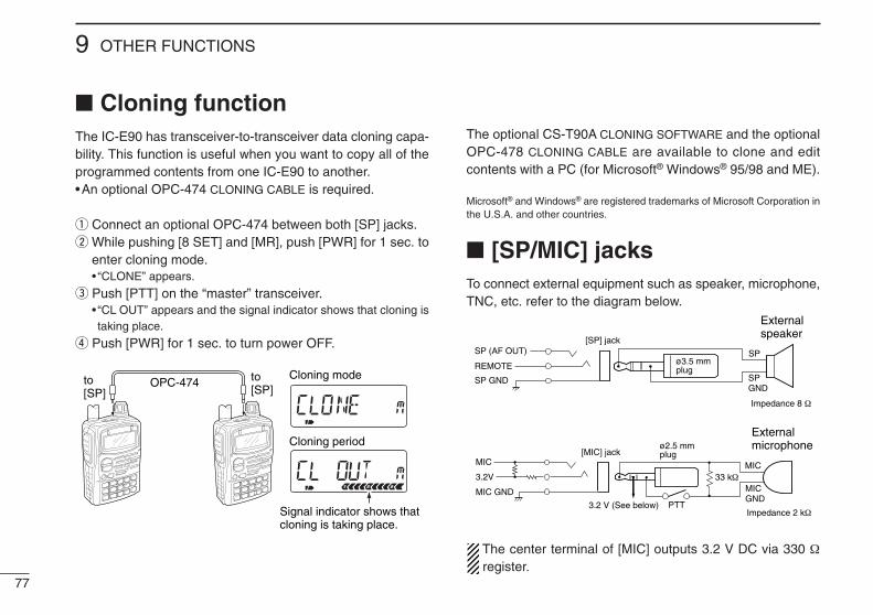
77
9 OTHER FUNCTIONS
Cloning functionThe IC-E90 has transceiver-to-transceiver data cloning capa-bility. This function is useful when you want to copy all of theprogrammed contents from one IC-E90 to another.•An optional OPC-474 CLONING CABLE is required.
q Connect an optional OPC-474 between both [SP] jacks.w While pushing [8 SET] and [MR], push [PWR] for 1 sec. to
enter cloning mode.• “CLONE” appears.
e Push [PTT] on the “master” transceiver.• “CL OUT” appears and the signal indicator shows that cloning istaking place.
r Push [PWR] for 1 sec. to turn power OFF.
The optional CS-T90A CLONING SOFTWARE and the optionalOPC-478 CLONING CABLE are available to clone and editcontents with a PC (for Microsoft® Windows® 95/98 and ME).
Microsoft® and Windows® are registered trademarks of Microsoft Corporation inthe U.S.A. and other countries.
[SP/MIC] jacksTo connect external equipment such as speaker, microphone,TNC, etc. refer to the diagram below.
The center terminal of [MIC] outputs 3.2 V DC via 330 Ωregister.
External speaker
[SP] jack
SP
SPGND
ø3.5 mmplug
[MIC] jack
33 kΩMIC
MICGND
External microphoneø2.5 mm
plug
PTT3.2 V (See below)
Impedance 8 Ω
Impedance 2 kΩ
MIC
3.2V
MIC GND
SP (AF OUT)
REMOTE
SP GNDOPC-474 to [SP]
to [SP]
Signal indicator shows that cloning is taking place.
Cloning period
Cloning mode
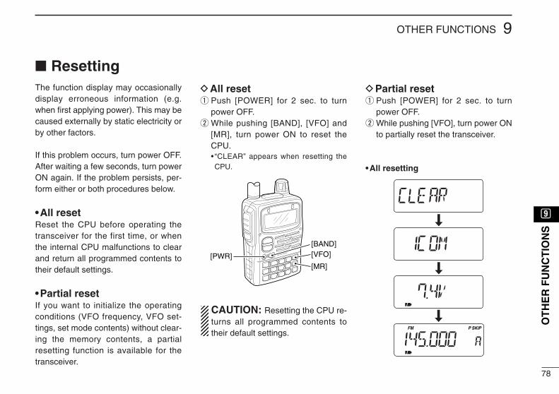
78
9OTHER FUNCTIONS
ResettingThe function display may occasionallydisplay erroneous information (e.g.when first applying power). This may becaused externally by static electricity orby other factors.
If this problem occurs, turn power OFF.After waiting a few seconds, turn powerON again. If the problem persists, per-form either or both procedures below.
•All resetReset the CPU before operating thetransceiver for the first time, or whenthe internal CPU malfunctions to clearand return all programmed contents totheir default settings.
•Partial resetIf you want to initialize the operatingconditions (VFO frequency, VFO set-tings, set mode contents) without clear-ing the memory contents, a partialresetting function is available for thetransceiver.
DAll resetq Push [POWER] for 2 sec. to turn
power OFF.w While pushing [BAND], [VFO] and
[MR], turn power ON to reset theCPU.• “CLEAR” appears when resetting theCPU.
CAUTION: Resetting the CPU re-turns all programmed contents totheir default settings.
DPartial resetq Push [POWER] for 2 sec. to turn
power OFF.w While pushing [VFO], turn power ON
to partially reset the transceiver.
•All resetting
FM SKIPP
[PWR]
[BAND][VFO]
[MR]
oo
OT
HE
R F
UN
CT
ION
S
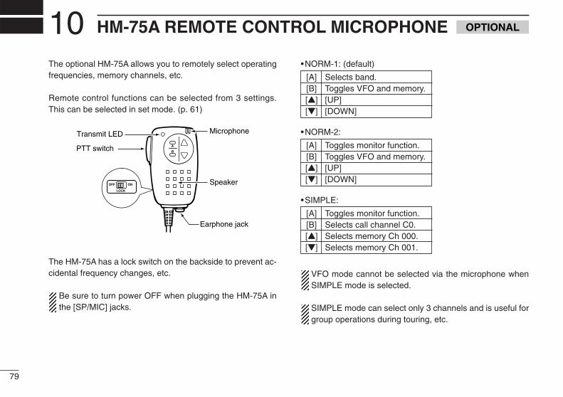
79
10 HM-75A REMOTE CONTROL MICROPHONE
The optional HM-75A allows you to remotely select operatingfrequencies, memory channels, etc.
Remote control functions can be selected from 3 settings.This can be selected in set mode. (p. 61)
The HM-75A has a lock switch on the backside to prevent ac-cidental frequency changes, etc.
Be sure to turn power OFF when plugging the HM-75A inthe [SP/MIC] jacks.
•NORM-1: (default)
[A] Selects band.[B] Toggles VFO and memory.[Y] [UP][Z] [DOWN]
•NORM-2:
[A] Toggles monitor function.[B] Toggles VFO and memory.[Y] [UP][Z] [DOWN]
•SIMPLE:
[A] Toggles monitor function.[B] Selects call channel C0.[Y] Selects memory Ch 000.[Z] Selects memory Ch 001.
VFO mode cannot be selected via the microphone whenSIMPLE mode is selected.
SIMPLE mode can select only 3 channels and is useful forgroup operations during touring, etc.
A
OFF ON
LOCK
BPTT switch
Transmit LED
Earphone jack
Microphone
Speaker
OPTIONAL

80
11TROUBLESHOOTING
If your transceiver seems to be malfunctioning, please checkthe following points before sending it to a service center.
!!00
!!11
HM
-75
RE
MO
TE C
ON
TRO
LM
ICR
OP
HO
NE
TRO
UB
LESH
OO
TIN
G
PROBLEM POSSIBLE CAUSE SOLUTION REF.No power comes on.
No sound comes from thespeaker.
Transmitting is impossible.
No contact possible withanother station.
Tuning dial or [Y]/[Z] func-tion is strange.
Frequency cannot be set.
No beep sound.
Receive audio is distorted.
Desired set mode itemcannot be selected.
Attached battery pack can-not be charged with theoptional BC-139.
•The batteries are exhausted.•The battery polarity is reversed.
•Volume level is too low.•Different tone is selected with tone/DTCS squelch.
•The batteries are exhausted.•The frequency outside of the 50/144/430 MHzamateur band is set.
•Different tone is selected with tone/DTCS squelch.
•Tuning dial and [Y]/[Z] functions are exchanged.
•The lock function is activated.•Memory or call channel is selected.
•Beep tones are turned OFF or the beep tone levelis too low.
•The operating mode is not selected correctly.
•The desired set mode item is in expanded setmode 1 or 2.
•Some set mode items can be selected from VFOor memory mode only.
•The transceiver’s power is ON. (The charging indi-cator blinking orange.)
•Replace the batteries or charge the battery pack.•Check the battery polarity.
•Push [Y] to obtain a suitable level.•Check the tone using tone/DTCS scan.
•Replace the batteries or charge the battery pack.•Reset the frequency inside the 50/144/430 MHzamateur bands.
•Check the tone using tone scan.
•Push [1 V↔D] for 1 sec. to cancel the function.
•Push [CALL/TV LOCK] for 1 sec. to cancel the function.•Push [VFO] to select VFO mode.
•Turn beep tone ON or set the beep tone level toappropriate level in set mode.
•Select a suitable operating mode in set mode.
•Turn the expanded set mode 1 or 2 ON.
•Enter set mode from appropriate operating mode.
•Detach the battery pack and charge the batteryonly.
pgs. 1, 14p. 1
p. 17p. 70
pgs. 13, 14p. 19
p. 70
p. 23
p. 74p. 20
p. 21
p. 21
p. 55
pgs. 17, 18,22, 27
—

CH Freq.1 50.752 60.753 67.754 180.755 187.756 194.757 201.758 208.759 215.7510 222.7511 229.75
CH Freq.
53 732.75
54 740.75
55 748.75
56 756.75
57 764.75
58 772.75
59 780.75
60 788.75
61 796.75
62 804.75
63 812.75
64 820.75
65 828.75
66 836.75
67 844.75
68 852.75
69 860.75
CH Freq.
31 556.75
32 564.75
33 572.75
34 580.75
35 588.75
36 596.75
37 604.75
38 612.75
39 620.75
40 628.75
41 636.75
42 644.75
43 652.75
44 660.75
45 668.75
46 676.75
47 684.75
48 692.75
49 700.75
50 708.75
51 716.75
52 724.75
CH Freq.
1 46.75
2 53.75
3 60.75
4 67.75
5 180.75
6 187.75
7 194.75
8 201.75
9 208.75
10 215.75
11 222.75
12 229.75
21 476.75
22 484.75
23 492.75
24 500.75
25 508.75
26 516.75
27 524.75
28 532.75
29 540.75
30 548.75
New Zealand channels
U.S.A. channels CCIR channels
81
12 TV FREQUENCY TABLE
CH Freq.2 59.753 65.754 71.755 81.756 87.757 179.758 185.759 191.7510 197.7511 203.7512 209.7513 215.7514 475.7515 481.7516 487.7517 493.7518 499.7519 505.7520 511.7521 517.7522 523.7523 529.7524 535.7525 541.75
CH Freq.26 547.7527 553.7528 559.7529 565.7530 571.7531 577.7532 583.7533 589.7534 595.7535 601.7536 607.7537 613.7538 619.7539 625.7540 631.7541 637.7542 643.7543 649.7544 655.7545 661.7546 667.7547 673.7548 679.7549 685.75
CH Freq.50 691.7551 697.7552 703.7553 709.7554 715.7555 721.7556 727.7557 733.7558 739.7559 745.7560 751.7561 757.7562 763.7563 769.7564 775.7565 781.7566 787.7567 793.7568 799.7569 805.75
The following tables show the channels versus audio fre-quencies depending on each version.
NOTE: The pre-programmed TV memories may differ depends onversion.

CH Freq.63 777.7564 784.7565 791.7566 798.7567 805.7568 812.7569 819.75
CH Freq.39 609.7540 616.7541 623.7542 630.7543 637.7544 644.7545 651.7546 658.7547 665.7548 672.7549 679.7550 686.7551 693.7552 700.7553 707.7554 714.7555 721.7556 728.7557 735.7558 742.7559 749.7560 756.7561 763.7562 770.75
CH Freq.0 51.751 62.752 69.753 91.754 100.755 107.75
5A 143.756 180.757 187.758 194.759 201.7510 214.7511 221.7528 532.7529 539.7530 546.7531 553.7532 560.7533 567.7534 574.7535 581.7536 588.7537 595.7538 602.75
Australian channels
82
12TV FREQUENCY TABLE
!!22
TV
FR
EQ
UE
NC
YTA
BL
E
CH Freq.45 669.2546 677.2547 685.2548 693.2549 701.2550 709.2551 717.2552 725.2553 733.2554 741.2555 749.2556 757.2557 765.2558 773.2559 781.2560 789.2561 797.2562 805.2563 813.2564 821.2565 829.2566 837.2567 845.2568 853.25
CH Freq.21 477.2522 485.2523 493.2524 501.2525 509.2526 517.2527 525.2528 533.2529 541.2530 549.2531 557.2532 565.2533 573.2534 581.2535 589.2536 597.2537 605.2538 613.2539 621.2540 629.2541 637.2542 645.2543 653.2544 661.25
UK channels
CH Freq.69 861.25
CH Freq.4 181.755 189.756 197.757 205.758 213.759 221.75
FOT channels

CH Freq.65 828.7566 836.7567 844.7568 852.7569 860.75
CH Freq.38 612.7539 620.7540 628.7541 636.7542 644.7543 652.7544 660.7545 668.7546 676.7547 684.7548 692.7549 700.7550 708.7551 716.7552 724.7553 732.7554 740.7555 748.7556 756.7557 764.7558 772.7559 780.7560 788.7561 796.7562 804.7563 812.7564 820.75
CH Freq.2 53.753 60.754 67.755 180.756 187.757 194.758 201.759 208.7510 215.7511 222.7521 476.7522 484.7523 492.7524 500.7525 508.7526 516.7527 524.7528 532.7529 540.7530 548.7531 556.7532 564.7533 572.7534 580.7535 588.7536 596.7537 604.75
CH Freq.55 853.7556 861.7557 869.7558 877.7559 885.7560 893.7561 901.7562 909.7563 917.7564 925.7565 933.7566 941.7567 949.7568 957.75
CH Freq.28 637.7529 645.7530 653.7531 661.7532 669.7533 677.7534 685.7535 693.7536 701.7537 709.7538 717.7539 725.7540 733.7541 741.7542 749.7543 757.7544 765.7545 773.7546 781.7547 789.7548 797.7549 805.7550 813.7551 821.7552 829.7553 837.7554 845.75
CH Freq.1 56.252 64.253 72.254 83.755 91.756 174.757 182.758 190.759 198.7510 206.7511 214.7512 222.7513 477.7514 485.7515 493.7516 501.7517 509.7518 517.7519 525.7520 533.7521 541.7522 549.7523 557.7524 565.7525 613.7526 621.7527 629.75
83
12 TV FREQUENCY TABLE
China channels Indonesian channels
CH Freq.7 179.758 185.759 191.7510 197.7511 203.7512 209.75
Taiwan channels
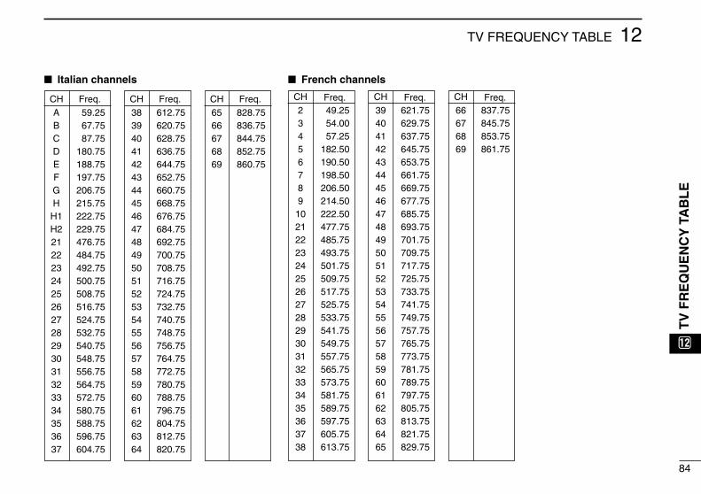
Italian channels
CH Freq.65 828.7566 836.7567 844.7568 852.7569 860.75
CH Freq.38 612.7539 620.7540 628.7541 636.7542 644.7543 652.7544 660.7545 668.7546 676.7547 684.7548 692.7549 700.7550 708.7551 716.7552 724.7553 732.7554 740.7555 748.7556 756.7557 764.7558 772.7559 780.7560 788.7561 796.7562 804.7563 812.7564 820.75
CH Freq.A 59.25B 67.75C 87.75D 180.75E 188.75F 197.75G 206.75H 215.75H1 222.75H2 229.7521 476.7522 484.7523 492.7524 500.7525 508.7526 516.7527 524.7528 532.7529 540.7530 548.7531 556.7532 564.7533 572.7534 580.7535 588.7536 596.7537 604.75
84
12TV FREQUENCY TABLE
!!22
TV
FR
EQ
UE
NC
YTA
BL
E
CH Freq.39 621.7540 629.7541 637.7542 645.7543 653.7544 661.7545 669.7546 677.7547 685.7548 693.7549 701.7550 709.7551 717.7552 725.7553 733.7554 741.7555 749.7556 757.7557 765.7558 773.7559 781.7560 789.7561 797.7562 805.7563 813.7564 821.7565 829.75
CH Freq.2 49.253 54.004 57.255 182.506 190.507 198.508 206.509 214.5010 222.5021 477.7522 485.7523 493.7524 501.7525 509.7526 517.7527 525.7528 533.7529 541.7530 549.7531 557.7532 565.7533 573.7534 581.7535 589.7536 597.7537 605.7538 613.75
French channels
CH Freq.66 837.7567 845.7568 853.7569 861.75

85
13 SPECIFICATIONS
DGeneral•Frequency coverage : (unit: MHz)
y
•Mode : FM, AM (Rx only), WFM (Rx only)
•No. of memory channels : 555 (500 regular, 50 scan edges,
and 5 call channels)
•Usable temp. range : –10°C to +60°C; +14°F to +140°F
•Tuning steps : 5, 6.25, 8.33, 9, 10, 12.5, 15, 20,25, 30, 50, 100 and 200 kHz
•Frequency stability : ±6 ppm (–10°C to +60°C)
•Power supply : 5.5 to 11.5 V DC or specified battery pack
•Current drain (at 8.0 V DC):Tx High 50 MHz 2.0 A (typical)
144, 430 MHz 2.0 A (typical)Tx Low 50, 144 MHz 0.8 A (typical)
430 MHz 1.2 A (typical)Rx rated audio 220 mA (typical)
standby 100 mA (typical)power saved 65 mA (typical)
•Antenna connector : SMA (50 Ω)•Dimensions : 58(W)×87(H)×29(D) mm;(projections not included) 2 9⁄32(W)×3 7⁄16(H)×1 5⁄32(D) in
•Weight (approx.) : 280 g; 9 29⁄32 oz(with antenna and BP-217)
#02 Europe,#03 UK#04Italy#10Europe-1
#11Spain#12France
Transmit50–52, 144–146,430–44050–51, 144–146,430–434, 435–438144–146, 430–440
144–146, 430–440
50.2–51.2, 144–146,430–440
Receive0.495–999.990
0.495–999.990
0.495–29.995,50–52, 76–135.995,144–146, 430–44050–50.2, 144–146,430–4400.495–29.995,50–52, 76–135.995,144–146, 430–440

86
13SPECIFICATIONS
DReceiver•Receive system : Double-conversion
superheterodyne• Intermediate frequencies : 1st 69.45 MHz (FM/AM)
13.35 MHz (WFM)2nd 450 kHz
•Sensitivity (except spurious points; typical values):FM 1.625–4.995 MHz 0.4 µV(at 12 dB SINAD) 5.000–49.995 MHz 0.18 µV
50.000–54.000 MHz 0.16 µV54.005–143.995 MHz 0.18 µV144.000–148.000 MHz 0.16 µV148.005–209.995 MHz 0.4 µV210.000–225.000 MHz 1.0 µV340.000–429.995 MHz 0.32 µV430.000–450.000 MHz 0.16 µV450.005–832.990 MHz 0.32 µV833.000–999.990 MHz 1.0 µV
WFM 40.000–108.0 MHz 1.0 µV(at 12 dB SINAD) 175–221.995 MHz 1.8 µV
470–770 MHz 3.2 µVAM 0.495–4.995 MHz 1.3 µV(at 10 dB S/N) 5.000–29.995 MHz 0.56 µV
118.000–136.000 MHz 0.5 µV222.000–229.995 MHz 0.79 µV320.000–329.995 MHz 1.0 µV
•Selectivity (except WFM) : Less than 15 kHz/–9 dBMore than 30 kHz/–60 dB
•Spurious and image rejection ratio:50, 144 MHz Less than –60 dB430 MHz Less than –50 dB(except half IF, 2nd image, 50 MHz band IF and WFM)
•Audio output power : 0.2 W typical at 10%(at 8.0 V DC) distortion with an 8 Ω load
•AF output impedance : 2-conductor 3.5(d) mm; 1⁄8″/8 Ω
DTransmitter•Modulation system : Variable reactance frequency
modulation•Output power : High 5 W(at 8.0 V DC) Low 0.5 W
•Spurious emissions : Less than –60 dB•Max. frequency deviation: ±5.0 kHz•Ext. MIC connector : 3-conductor 2.5(d) mm; 1⁄10″
/2 kΩ
All stated specifications are subject to change withoutnotice or obligation.
!!33
SP
EC
IFIC
AT
ION
S

AD-92SMA ANTENNA CONNECTOR ADAPTERAllows you to connect an antenna with a BNC connector.(SMA to BNC adapter)
BC-110D/DR WALL CHARGERRegularly charges BP-217 Li-ion battery pack in 15 hrs.
BC-139 DESKTOP CHARGERRapidly charges BP-217 Li-ion battery pack in 2 hrs. and 30min.
BP-216 BATTERY CASEBattery case for R6 (AA) × 2 alkaline batteries.
BP-217 Li-Ion BATTERY PACK7.4 V/1500 mAh (Min.)/1580 mAh (Typ.) Lithium Ion batterypack. Approx. 6 hrs. and 20 min. operating time at 50M bandwith high power, Tx : Rx : Standby = 1:1:8.
HM-54 SPEAKER-MICRO-PHONEDurable full-sized speaker-mi-crophone.
HM-75A REMOTE CONTROLMICROPHONEAllows you to remotely selectoperating channels, etc.
HM-131 SPEAKER-MICRO-PHONEFor operation while conve-niently hanging the transceiverfrom your belt, etc.
HM-128 EARPHONE-MICROPHONEIdeal for hands-free operation by clipping the microphone withPTT switch to your lapel or breast pocket.
BC-123E(supplied with BC-139)
Charger adapter
Desktop charger
87
14 OPTIONS
HM-54
HM-75A
HM-131

HS-94 EARHOOKHEADSET + VS-1VOX/PTT UNITFlexible boom micro-phone and rotating ear-piece with a springearhook.
SP-13 EARPHONEProvides clear receiveaudio in noisy environ-ments.
LC-152A CARRYING CASEHelps protect the transceiver from scratches, etc.
CP-19R CIGARETTE LIGHTER CABLE WITH NOISE FILTERUsed for operation and charging a battery pack connected tothe transceiver via a DC power source. (11.5–16 V DC)
CS-T90A CLONING SOFTWARE + OPC-478 CLONINGCABLEAllows you to transfer data from memories, etc. and quicklyand easily edit and store data via a PC for Microsoft®
Windows® 95/98 and ME. 1 RS-232C (COM) port is required.
OPC-474 CLONING CABLE Used for handheld-to-handheld cloning.
CP-19R
88
14OPTIONS
Microsoft® and Windows® are registered trademarks of Microsoft Cor-poration in the U.S.A. and other countries.
VOX
PTT
HS-94VS-1
!!44
OP
TIO
NS

Blank page

T
V c
han
nel
mo
de
sele
ctio
nP
ush
[CA
LL
/TV
] se
vera
l tim
es.
T
V c
han
nel
sel
ecti
on
Rot
ate
[DIA
L].
T
V c
han
nel
ski
p s
etti
ng
q S
elec
t TV
cha
nnel
mod
e.w
Rot
ate
[DIA
L]
to s
elec
t des
ired
chan
nel.
e P
ush
and
hold
[5
SK
IP]
for
1 se
c.
C
ance
llin
g s
kip
set
tin
gq
Sel
ect T
V c
hann
el m
ode.
w W
hile
pus
hing
[B
AN
D],
rot
ate
[DIA
L]
to s
elec
t des
ired
skip
ch
anne
l.e
Pus
h an
d ho
ld [
SK
IP]
for
1 se
c.
E
xch
ang
e [D
IAL
] an
d [
∫]/
[√]
assi
gn
men
tP
ush
and
hold
[1
V↔
D]
for
1 se
c.
K
ey lo
ck f
un
ctio
nP
ush
and
hold
[C
AL
L/T
V]
for
1 se
c. to
tu
rn th
e lo
ck fu
nctio
n O
N a
nd O
FF
.
S
ET
mo
de
op
erat
ion
q P
ush
and
hold
[8
SE
T]
for
1 se
c.w
Rot
ate
[DIA
L]
to s
elec
t SE
T m
ode
item
.e
Pus
h [8
SE
T]
mom
enta
rily,
then
ro
tate
[D
IAL
] to
cha
nge
the
setti
ng.
r P
ush
[8 S
ET
] m
omen
taril
y to
ret
urn
to th
e co
nditi
on o
f ste
p w
.t
Pus
h [V
FO
] to
exi
t the
SE
T m
ode.
C
PU
res
et o
per
atio
n•
AL
L r
eset
q T
urn
pow
er O
FF
.w
Whi
le p
ushi
ng a
nd h
oldi
ng [
BA
ND
],
[VF
O]
and
[MR
], tu
rn p
ower
ON
.
• P
arti
al r
eset
q T
urn
pow
er O
FF
.w
Whi
le p
ushi
ng a
nd h
oldi
ng [
VF
O],
tu
rn p
ower
ON
.
FMSK
IPP
1 V
D
2TO
NE
BA
NDD
3 H/L
MO
DE
SC
AN
VF
OM
Hz
iC- e
90
4 DU
P5 SK
IP6 M
.N0 R
ITM
RS
.MW
7T.
SC
AN
8 SE
T9 T
S.
DTM
F.M
CALL
/TV
LO
CK
A B C
MU
LTIB
AN
D T
RA
NS
CE
IVE
R
PO
CK
ET
GU
IDE
Important operating instructions are summed up in this and the following pagefor your simple reference.
By cutting along the line and folding on the dotted line, it will become a cardsized operating guide which can easily be carried in a card case or wallet,etc.
q Cut w Fold e Complete
<C
UT
HE
RE
>
POCKET GUIDE

QUICK REFERENCE
V
FO
/ME
MO
RY
MO
DE
selection
VF
O m
ode: P
ush [VF
O].
ME
MO
RY
mode
: Push [M
R].
C
han
gin
g freq
uen
cy ban
dP
ush [BA
ND
].
F
requ
ency settin
gq
Select V
FO
mode.
w R
otate [DIA
L], or enter the desired
frequency from the keypad.
[e.g. 1] 445.600 MH
z[4], [4], [5], [•], [6], [0], [0][e.g. 2] 0.684 M
Hz
[0], [•], [6], [8], [4]
C
han
gin
g receivin
g m
od
eP
ush [MO
DE
].
A
dju
sting
aud
io o
utp
ut level
Push [∫
]/[√] (continuously changes
while holding).
A
dju
sting
squ
elch level
While pushing [S
QL
] rotate [DIA
L].
M
EM
OR
Y ch
ann
el selection
q S
elect ME
MO
RY
mode.
w R
otate [DIA
L], or use keypad.
M
EM
OR
Y ch
ann
el pro
gram
min
g[e.g.] P
rogram 445.600 M
Hz into M
R
CH
2q
Select V
FO
mode.
w R
otate [DIA
L], or use keypad to
set 445.600 MH
z.e
Push and hold [M
R S
.MW
] for 1 sec. to indicate m
emory channels.
r R
otate [DIA
L] to select M
R C
H 2.
t P
ush and hold [MR
S.M
W] for
1 sec. (VF
O m
ode is selected after program
ming.)
M
EM
OR
Y ch
ann
el clearing
q S
elect the desired mem
ory channel. w
Push and hold [M
R S
.MW
] for 1 sec.w
Push [C
AL
L/T
V] several tim
es to select “C
LR”.
e P
ush and hold [MR
S.M
W] for
1 sec. to clear the information.
S
cann
ing
in V
FO
mo
de
q S
elect VF
O m
ode.w
While pushing and holding [M
OD
E
SC
AN
], rotate [DIA
L] to select
scan edge from full (A
LL
), band (B
AN
D) and program
(PR
OG
0–24) scans.
e R
elease [MO
DE
SC
AN
] to start the scan.
r P
ush [VF
O] to stop the scan.
S
cann
ing
in M
EM
OR
Y m
od
eq
Select M
EM
OR
Y m
ode.w
For the m
emory bank scan, push
[MR
] to select mem
ory bank mode
and push [BA
ND
] to select the de-sired m
emory bank.
e W
hile pushing and holding [MO
DE
S
CA
N], rotate [D
IAL
] to select scan m
ode from m
emory (A
LL
) and bank (B
AN
K) scans.
r R
elease [MO
DE
SC
AN
] to start the scan.
t P
ush [VF
O] to stop the scan.

CE
We Icom Inc. Japan1-1-32, Kamiminami, Hirano-kuOsaka 547-0003, Japan
Kind of equipment: MULTIBAND TRANSCEIVER
This compliance is based on conformity according to Annex III of the directive 1999/5/EC using the following harmonised standards:i) Article 3.1a EN 60950: 1992+A11 ii) Article 3.1b EN 301489-1 and EN 301489-15iii) Article 3.2 EN 301 783-2iv) v)
Type-designation: iE90
Declare on our sole responsibility that this equipment complies with theessential requirements of the Radio and Telecommunications Terminal Equipment Directive, 1999/5/EC, and that any applicable Essential TestSuite measurements have been performed.
Version (where applicable):
Signature
Authorized representative name
Place and date of issue


1-1-32 Kamiminami, Hirano-ku, Osaka 547-0003, Japan
A-6135H-1EU-rPrinted in Japan© 2002–2009 Icom Inc.
<Intended Country of Use> GER NED ITA AUT BEL GRE GBR LUX SWE IRL ESP DEN FRA POR FIN SUI
#02 Europe#10 Europe-1
<Intended Country of Use> GER NED ITA AUT BEL GRE GBR LUX SWE IRL ESP DEN FRA POR FIN SUI
#03 UK
<Intended Country of Use> GER NED ITA AUT BEL GRE GBR LUX SWE IRL ESP DEN FRA POR FIN SUI
#04 Italy
<Intended Country of Use> GER NED ITA AUT BEL GRE GBR LUX SWE IRL ESP DEN FRA POR FIN SUI
#11 Spain
<Intended Country of Use> GER NED ITA AUT BEL GRE GBR LUX SWE IRL ESP DEN FRA POR FIN SUI
#12 France