Embed Size (px)
Citation preview

Instruction Manual
Hakomatic B30 (7715)
Instruction Manual
Hakomatic B30 (7715)
2
IntroductionPrefaceDear customer, It is our desire that the good characteristics of the Hakomatic B30 should justify the confidence you demonstrated by making this purchase.Prior to the first use, read the chapter "Safety Information” carefully as this will ensure safe operation of the machine. Your own safety, as well as the safety of others, depends to a great extent on how the machine is moved and opera-ted. Therefore, this operation and main-tenance manual must be read and understood prior to the machine being used for the first time.The manual provides valuable informa-tion about operation, service and maintenance. The warning symbols as used in this manual identifies items re-levant to safety. Please observe the safety provisions (see chapter "Safety Information”).Your authorized Hako dealer will be ple-ased to answer further questions regar-ding the machine or the operation and maintenance manual.
Please be advised explicitly that we cannot accept any legal issues out of the contents of this manual.If repair work has to be performed make sure that only genuine spare parts are used; only genuine spare parts may guarantee a dependable machine.We reserve the right for technical im-provement..
Valid as of: January 2009
Hako-Werke GmbHD-23843 Bad OldesloeHamburger Str. 209-239Telefon ++49 (04531) 8060
Proper useThe machine is a vacuum scrubbing machine for wet cleaning of hard-sur-faced floors. Using the machine beyond this scope of application will be deemed improper use; The manufacturer cannot be held liable for consequential dama-ges; the user alone bears the risk.The term of proper use also includes operation, maintenance and repair work to be performed in compliance with the manufacturer's specifications. The Hakomatic B30 may only be used by persons that are familiar with the ma-chine and aware of possible hazards involved.If modifications to the machine are made in absence of the manufacturer's prior consent, the latter cannot be held liable for damage resulting from such unauthorized modification.
Introduction

3
Notes on warrantyThe terms of the sales contract apply. Damages are not subject to warranty if they are due to non-compliance with the maintenance and service provisions. The maintenance work has to be perfor-med by an authorized Hako service center and confirmed in the "Mainte-nance certificate" which is the warranty document.The following is excluded from warranty: fuses, natural wear, damages caused by overload, inexpert handling and unauthorized modification of the machine. Moreover, any claim for war-ranty cannot be accepted if damages of the machine are caused by fitting parts or accessories without Hako’s prior and explicit consent or by non-compliance with the maintenance instructions.
Acceptance of the machineUpon arrival, check machine for possi-ble damages in transit. For refund of such damage, have the Deutsche Bahn AG or your freight forwarder confirm such damage. Mail notification and waybill to:
Hako-Werke GmbHHamburger Strasse 209-23923843 Bad Oldesloe
Introduction

4
Table of Content
Introduction . . . . . . . . . . . . . 2Preface. . . . . . . . . . . . . . . . . . 2Proper use . . . . . . . . . . . . . . . 2Notes on warranty . . . . . . . . . 3Acceptance of the machine . . 3
1 Safety information . . . . . . . . 51.1 Safety and Warning Symbols. 51.2 General Provisions. . . . . . . . . 61.3 Operating information. . . . . . . 61.4 Maintenance information . . . . 71.5 Specific Hazards . . . . . . . . . . 81.6 Information for Protection of En-
vironment . . . . . . . . . . . . . . . . 81.7 Labels on the machine . . . . . . 9
2 First Operation . . . . . . . . . . 102.1 Instruction. . . . . . . . . . . . . . . 102.2 Initial charging procedure. . . 102.3 Before Putting into Operation 102.4 Switching the machine on . . 102.5 Operation . . . . . . . . . . . . . . . 112.5.1 Useful tips . . . . . . . . . . . . . . 122.5.2 Error code table . . . . . . . . . . 122.6 Stopping and switching off the
machine . . . . . . . . . . . . . . . . 132.7 After completing work. . . . . . 132.8 Transportation and lashing
points . . . . . . . . . . . . . . . . . . 13
3 Operation . . . . . . . . . . . . . . 143.1 Method of operation . . . . . . . 143.1.1 Brush head. . . . . . . . . . . . . . 143.1.2 Solution tank . . . . . . . . . . . . 143.1.3 Squeegee. . . . . . . . . . . . . . . 153.1.4 Recovery tank . . . . . . . . . . . 153.1.5 Power flow / traction drive . . 153.1.6 Batteries and charger. . . . . . 163.1.7 Options. . . . . . . . . . . . . . . . . 163.2 Operating and indicator
elements. . . . . . . . . . . . . . . . 173.2.1 Operating panel . . . . . . . . . . 173.2.2 Operating elements on the
machine . . . . . . . . . . . . . . . . 23
4 Technical Data . . . . . . . . . . 255 Maintenance and Care . . . . 275.1 Hako System Maintenance . 275.2 Maintenance Document . . . . 285.3 Maintenance Schedule. . . . . 295.4 Battery system . . . . . . . . . . . 335.4.1 Charging batteries . . . . . . . . 345.4.2 Total discharge signal
transducer (TSG) . . . . . . . . . 345.4.3 Servicing the driving
batteries . . . . . . . . . . . . . . . . 345.4.4 Removing the batteries . . . . 345.4.5 Inserting the batteries. . . . . . 34
5.4.6 Disposing of batteries. . . . . . 345.5 Solution tank . . . . . . . . . . . . 355.5.1 Filling the solution tank. . . . . 365.5.2 Emptying the solution tank . . 365.5.3 Cleaning the fresh water filter365.6 Soiled Water tank. . . . . . . . . 375.6.1 Empty Soiled Water Tank . . 385.6.2 Clean Soiled Water Tank . . . 385.6.3 Clean Suction Filter . . . . . . . 385.6.4 Checking the Draining valve
seal. . . . . . . . . . . . . . . . . . . . 385.6.5 Checking the Tank lid seal . . 385.7 Brush head. . . . . . . . . . . . . . 395.7.1 Changing the brushes . . . . . 405.7.2 Changing the deflector roller 405.7.3 Changing the sealing strip . . 405.8 Squeegee. . . . . . . . . . . . . . . 415.8.1 Cleaning the squeegee . . . . 415.8.2 Changing the sealing strips . 415.8.3 Adjusting the sealing strips . 42
EC-Declaration of Conformity . . . . . . . . . . . . . 45

5
Safety information
1 Safety information1.1 Safety and Warning SymbolsAll paragraphs in this manual referring to your personal safety, the safety of your machine and the environment pro-tection are attributed one of the follo-wing warning symbols:
Symbol Hazardous for ... Description
Safety Provisions persons and goods Safety Provisions in dangerous situation caused by misuse inaccurate adherence of instructions or pres-cribed work routine.
CAUTION the machine important information on handling the machine in order to maintain operability.
Ecological hazard the environment due to use of substances representing an inherent danger to health of environment

6
Safety information
1.2 General Provisions• Apart from the provisions contained
in this instruction manual, the gene-ral safety provisions and the acci-dent prevention regulations as imposed by law have to be complied with.
• Before taking your machine into ope-ration, carefully read the instruction manual as well as other separate in-structions for accessories or atta-ched implements and comply with all points mentioned there during work.
• Persons being trained by qualified Hako technicians only are authori-sed to operate, service and repair the machine.
• You are advised to thoroughly study the safety instructions since precise knowledge only helps avoiding er-rors during operation of the machine and thus guarantee faultless usage of the machine.
• The operating instructions have to be at hand at the place of use of the machine, and therefore have to be kept readily available at the machi-ne.
• When selling or letting the machine for rent, hand out these documents
to the new owner/operator and have the transfer certified!
• The warning and instruction plates attached to the machine contain va-luable advice about safe operation. Immediately replace incomplete or il-legible labels.
• As far as safety standards are con-cerned, spare have to equal genuine spare parts!
1.3 Operating information• Before starting the machine up for
the first time, the battery to be used must be fully charged, properly, by implementing the initial battery char-ge routine. Please pay attention to the operating manual provided with the charging unit as well as the ma-nual from the battery manufacturer. Hako assumes no liability for dama-ge to the battery caused by a fault when the battery is charged for the first time.
• Check the operational safety of the machine each time before starting it up! Clear any faults immediately!
• Before starting work, the operator must be fully familiar with all adjust-ment, operating and control ele-
ments as well as their respective function! It is too late to do this when the machine is actually in operation!
• Always wear heavy duty, non-slip footwear when working with the ma-chine.
• The machine may only be driven on and the equipment used on those surfaces which have been approved by the contractor or person appoin-ted by him.
• When using the machine, it is essen-tial to pay attention to third parties, especially children.
• Start driving immediately after swit-ching on the brush head drive other-wise imprints of the brush could be produced on the floor.
• Only use cleaning agents suitable for the vendor (non-foaming) and obser-ve all the use, disposal and warning information provided by the cleaning agent manufacturer.
• Only open empty recovery tanks.• The machine is not suitable for clea-
ring up hazardous, inflammable or explosive fluids, dust or substances.
• It is forbidden to use the machine in potentially explosive atmospheres.
• To prevent unauthorized use of the

7
Safety information
machine, remove the key from the main switch (Hakomatic B30 CL/CLH only).
• When transporting the machine, the squeegee and brush head must be raised. The way of driving must be adapted to the local conditions.
• The machine has been conceived for use on level surfaces with a maxi-mum gradient of 2%.
1.4 Maintenance information• Operating personnel must complete
the necessary daily and weekly maintenance work. All other mainte-nance work must be completed at your nearest Hako service center.
• The maintenance work and mainte-nance intervals prescribed in the operating manual must be adhered to.
• Suitable tools must be used for clea-ning and maintenance work.
• The machine must be inspected by a recognized technical expert in re-spect of operational safety, within the terms of the applicable accident prevention laws, at reasonable inter-vals (we recommend at least once a year) and following modification or
repairs .• Spare parts must comply with the mi-
nimum technical requirements stipu-lated by the manufacturer! This is ensured by the use of original spare parts.
• Before cleaning and servicing the machine or replacing parts, switch off the motors and main switch (Ha-komatic B30 CL/CLH only).
• To prevent unauthorized use of the machine, remove the key from the main switch (Hakomatic B30 CL/CLH only).
• Always disconnect the battery termi-nal before starting any work on the electrical installation.
• When working in the area of the rai-sed recovery tank, it must be hinged open fully to prevent it being kno-cked shut or further open and down unintentionally.
• It is not permitted to clean the machi-ne with a pressure washer or steam blaster.
• It is not permitted to use aggressive and corrosive cleaning agents.
• Allow the machine to dry after being cleaned, e.g. over the weekend.
• Only start the machine up when all
the safety equipment has been in-stalled and brought to its protecting position.
1.5 Specific HazardsElectric system• Only use genuine fuses with the
specified ratings.• In case of malfunction of the electric
system, immediately shutdown ma-chine and remedy.
• Only qualified personnel are authori-zed to work on the electrical installa-tions and only according to electro-technical rules.
• Inspect/check the electrical equip-ment of the machine at regular inter-valls. Clear up any defects immediately, such as loose connec-tions or damaged cables.
Battery• Respect the operating instructions of
the battery manufacturer.• Never place metal objects or tools on
batteries - short-circuit hazard!• Due to alteration of the centre of gra-
vity, only use batteries as released and at the prescribed position only.
• Only charge batteries in areas with sufficient ventilation. – Explosion ha-

8
Safety information
zard!• Refer to safety provisions in supple-
ment 88-60-2554 - Information on drive batteries.
1.6 Information for Protection of Environment
• For safe use of substances inheriting a danger to health and environment specific knowledge is required.
• Observe the legal directives and lo-cal regulations for disposal of deter-gents, see Water Management Act.
• Used batteries labelled as recyclable contain reusable economic goods. According to the crossed dustbin la-bel these batteries must not be ad-ded to the normal waste. Provide for agreement with the Hako contract dealer on return and disposal accor-ding to § 8 BattV.

9
Safety information
1.7 Labels on the machineThe following safety and warning labels are attached to the machine where easily legible. Missing or illegible labels must be replaced immediately.
Company logo (Fig. 1/1)
Rating plate (Fig. 1/2a)
Explosive gases (Fig. 1/2b)
Waste water draining hose (Fig. 1/3)
A = Read and observe the operating manual (Fig. 1/4)B = Maximum permissible gradient 2%(Fig. 1/4)C = Do not clean the machine with a pressure washer (Fig. 1/4)
Fig.1 Hakomatic B30
A
B
C
3
4
1
2

10
First Operation
2 First Operation2.1 InstructionInstruction is required before first ope-ration. First instruction into handling of the machine must be held by a qualified person sent by your local Hako contract dealer. Your Hako dealer will be infor-med by the manufacturer upon delivery of the vehicle and will contact you to make a date for instruction.
2.2 Initial charging procedure
Before first operation of the machine, fully charge the bat-tery with an initial charging pro-cedure and comply with the operating instructions of the charger as well as with those of the battery manufacturer. Hako cannot be held liable for damages resulting from an in-sufficient initial charge.
2.3 Before Putting into OperationComplete the following inspections be-fore taking the machine into operation:1. Check the area around the machine
for signs of leakage. Hoses, lines and tanks must be free from any lea-kage or damage.
2. Install brushes and squeegee, see maintenance chapter.
3. Install batteries and connect battery plug, see maintenance chapter.
4. Check battery charge and proceed to re-charging of batteries if required. Generally proceed to initial charging before first operation of the machine.
5. Empty recovery tank and clean it if required, see maintenance chapter.
6. Re-fill solution tank and add cleaning agent according to the manufactur-er's recommendations.
Use only cleaning agents sui-table for automatic machines (low-foaming) and comply with the instructions for use, dispo-sal and with the warning infor-mation specified by the cle-aning agent's manufacturer.
2.4 Switching the machine on
Before switching the machine on, please read the safety in-formation in Chapter 1.
Carry out the following preliminary work so that the machine is ready to operate:• If necessary, disconnect the power
plug of the charging device from the socket and place it in the holder. If the power plug is not inserted pro-perly in the holder (Fig. 2/1), the ma-chine is not ready to operate!
Fig.2
1

11
First Operation
• Switch the machine on by actuating the switch (Fig. 3/1) from position (0) to position (1).
Fig.3
2.5 Operation
Hakomatic B301. Switch the machine on at the main
switch. The suction turbine is swit-ched on.
2. Lower the squeegee using the squeegee lever.
3. Lower the brush head using the foot pedal.
4. Draw back the bar on the bail sy-stem. The brush head drive and so-lution supply are switched on.
5. Set the solution quantity with the hand valve.
6. Push the machine. The power flow of the brush head drive supports the forward drive.
Start driving immediately after switching on the brush head drive otherwise imprints of the brush could be produced on the floor. Raise the brush head when driving over thresholds.
Hakomatic B30 CL/CLH1. Switch the machine on using the key
switch. All the units are in Standby2. Lower the squeegee using the
squeegee lever. The suction turbine is switched on.
3. Lower the brush head using the foot pedal.
4. Pull the dead-man's switch on the bail system. The brush head drive is switched on.
5. Set the solution quantity using the button on the operating panel.
6. Set the driving direction and speed using the bail system.
7. To alter the cleaning intensity of the cleaning process, use the buttons on the operating panel to change the solution quantity and switch the solu-tion supply on and off.
Start driving immediately after switching on the brush head drive otherwise imprints of the brush could be produced on the floor. Raise the brush head when driving over thresholds.
1
A B

12
First Operation
2.5.1 Useful tipsBefore beginning wet cleaning, sweep the floor. This not only improves the cleaning effect but also reduces the ma-chine's liability to wear. The floor should be treated twice in the case of particularly dirty floors or to re-move wax (thorough cleaning). During the first cleaning process, the floor is scrubbed with a cleaning agent dosage appropriate to the degree of soiling, whereby the squeegee is raised.The cleaning agent is left to act on the floor for approx. 5 to 10 minutes accor-ding to the manufacturer's instructions, then scrub the floor again and, after that, treat it with the squeegee lowered.
Important information: pay attention to the correct dosage of the cleaning agent. The correct dosage helps to re-duce costs and protect the environ-ment. The development of excessive foam impairs the machine's function. It indicates there is too much cleaning agent or the wrong one has been selec-ted for the cleaning process being com-pleted. Unused component parts of a cleaning agent which end up in the wa-ste water lead to the development of fo-
am. Information on dosage is provided on the cleaning agent container. Use the manufacturer's information as an in-itial basis. Practical experience will ensure that you quickly find out which is the right Hako cleaning agent and the optimum dosage to suit your needs.
2.5.2 Error code tableIn addition to the Service indicator (wrench), a four-digit service code ap-pears in the indicator field. The dots in the service code flash. Clear the fault or note down the service code and inform your authorized Hako dealer.
Error Cause Remedy1.2.5.2. Brush motor overload Let the brush motor cool down
1.2.6.1. Brush is blocked Remove foreign bodies
1.2.6.5. Brush semiconductor Allow the machine to cool down or inform Hako service
1.2.6.6. Brush is not installed Install the brush
1.4.2.1. Suction turbine semiconductor Allow the machine to cool down or inform Hako service
3.2.1.1. Invalid TSG setting Inform Hako service
4.6.1.2. Internal SE error Inform Hako service

13
First Operation
2.6 Stopping and switching off the machine
Hakomatic B301. Stop the drive and release the safety
switch:- The brush drive and solution supply
are switched off2. Raise the brush head.3. Raise the squeegee.4. Switch off the machine with the main
switch.Hakomatic B30 CL/CLH1. Release the safety switch:
- The traction drive, brush drive and solution supply are switched off.
2. Raise the brush head.3. Raise the squeegee.
- The suction turbine continues to run approx. 10 seconds.
4. Switch off the machine with the key switch.
5. The machine must be protected and secured against being started up ac-cidentally and uncontrolled move-ments.
2.7 After completing work1. Drive to an appropriate maintenance
area.2. Stop the machine and switch it off.3. Empty the recovery tank and flush it.
Observe the applicable laws and local regulations when dis-posing of cleaning agents.
4. Check the solution filter.5. Check the sealing strips and suction
hose.6. Check the electrical equipment,
functions and settings.7. Clean the machine.8. Charge the batteries.If the machine is to be shutdown for a longer period, the solution tank must be emptied.
It is not permitted to clean the machine with a pressure was-her or steam blaster.
2.8 Transportation and lashing points
When running the machine to the site of use, the squeegee and brush head must be raised.When the machine is to be transported on another vehicle or trailer, it must be secured against rolling away. Lash the machine down securely. To do this, it must be secured at the front (on both si-des) and rear at the eye bolts (Fig. 4/1).
Fig.4 Hakomatic B30
1

14
Operation
3 Operation3.1 Method of operationGeneral informationThe Hakomatic B30 is a scrubber dryer for the wet cleaning of hard floors.
3.1.1 Brush headThe brush in the brush head (Fig. 5/1) is driven by an electric motor. The brush head is lowered by means of the brush pedal. The floor is cleaned by the rotary brush and cleaning agent. The brush can be removed for maintenance pur-poses by pressing a button.
3.1.2 Solution tankThe solution tank (Fig. 5/2) is filled through a detachable filling neck. The Hakomatic B30 solution tank has a vo-lume of approx. 30 liters. The fill level can be seen through a transparent ho-se. The cleaning agent quantity can be regulated.
Fig.5 Hakomatic B30
2
1
15
Operation
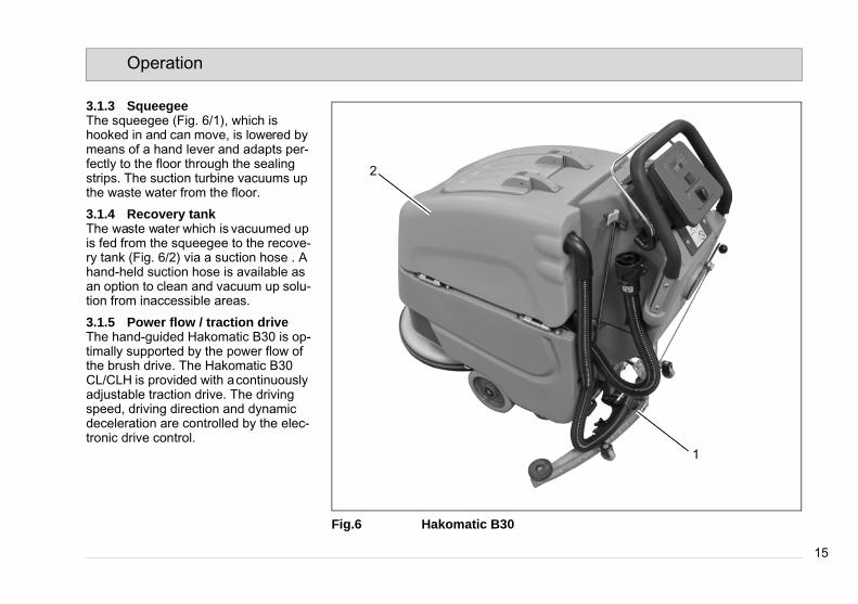
3.1.3 SqueegeeThe squeegee (Fig. 6/1), which is hooked in and can move, is lowered by means of a hand lever and adapts per-fectly to the floor through the sealing strips. The suction turbine vacuums up the waste water from the floor.
3.1.4 Recovery tankThe waste water which is vacuumed up is fed from the squeegee to the recove-ry tank (Fig. 6/2) via a suction hose . A hand-held suction hose is available as an option to clean and vacuum up solu-tion from inaccessible areas.
3.1.5 Power flow / traction driveThe hand-guided Hakomatic B30 is op-timally supported by the power flow of the brush drive. The Hakomatic B30 CL/CLH is provided with a continuously adjustable traction drive. The driving speed, driving direction and dynamic deceleration are controlled by the elec-tronic drive control.
Fig.6 Hakomatic B30
2
1
15
Operation
3.1.3 SqueegeeThe squeegee (Fig. 6/1), which is hooked in and can move, is lowered by means of a hand lever and adapts per-fectly to the floor through the sealing strips. The suction turbine vacuums up the waste water from the floor.
3.1.4 Recovery tankThe waste water which is vacuumed up is fed from the squeegee to the recove-ry tank (Fig. 6/2) via a suction hose . A hand-held suction hose is available as an option to clean and vacuum up solu-tion from inaccessible areas.
3.1.5 Power flow / traction driveThe hand-guided Hakomatic B30 is op-timally supported by the power flow of the brush drive. The Hakomatic B30 CL/CLH is provided with a continuously adjustable traction drive. The driving speed, driving direction and dynamic deceleration are controlled by the elec-tronic drive control.
Fig.6 Hakomatic B30
2
1

16
Operation
3.1.6 Batteries and chargerThe machine is equipped with mainte-nance-free batteries (Fig. 7/1), a fully automatic battery charger (Fig. 7/2) and a total discharge signal transducer (TSG) to protect it against total dischar-ge. Pay attention here to the safety in-formation. For information on driving batteries, refer to supplementary sheet 88-60-2556
3.1.7 Options• Hand-held suction hose incl.
cleaning tools (7036.40)• Mop holder and tool net for cleaning
tools (7725)• Dosing system (7056.02)• Float unit (7715)Hakomatic B45 CL/CLH only:• Tool connector (7724)• Floor scrubbing unit (7009)Hakomatic B45 CL only:• Silence kit (7730)
Please refer to our spare parts catalogue in Internet under www.hako.com for information on accessories such as brus-hes, rollers, pads, drive plates with centerlock and suction lips. Fig.7 Hakomatic B30
12

17
Operation
3.2 Operating and indicator elements
3.2.1 Operating panelHakomatic B301 Indicator field for:
- Operating hour counter- Service indicator and- TSG indicator
2 Charge control indicator3 Main switch4 Dead-man's switch5 Brush ejector
Fig.8 Hakomatic B30
1 2
5 3 4
17
Operation
3.2 Operating and indicator elements
3.2.1 Operating panelHakomatic B301 Indicator field for:
- Operating hour counter- Service indicator and- TSG indicator
2 Charge control indicator3 Main switch4 Dead-man's switch5 Brush ejector
Fig.8 Hakomatic B30
1 2
5 3 4

18
Operation
Indicator field (Fig. 8/1)The indicator field provides a central function monitoring facility and indica-tes all operating states.
Operating hour counterAfter switching on the software version, the last service code and current num-ber of operating hours appear briefly in the indicator field. The TSG (total discharge signal) indicator then ap-pears.
Service indicatorThe service indicator lights up when an error has occurred in the system and the cleaning or driving process is inter-rupted. In addition to the Service indica-tor (wrench), a four-digit service code appears in the indicator field. The dots in the service code flash.Clear the fault or note down the service code and inform your authorized Hako dealer.
Total discharge signal indicatorAfter switching the machine on, the TSG (total discharge signal transducer ) indicator appears in the indicator field. The four icons indicate the current battery charge status during operation.Frame flashes = batteries emptyCharge the batteries, refer to section 5.41 icon lights up = 25% charge2 icons light up = 50% charge3 icons light up = 75% charge4 icons light up = 100% charge
Charge control indicator (Fig. 8/2)The charge control indicator appears in the indicator field during charging. The current battery charge status is indica-ted during the charging process.The number of LEDs lit up corresponds to the following charge status:2 LEDs light up = charging has started3 LEDs light up = 75% charge
4 LEDs light up = 100% chargeA flashing LED indicates an error in the charger, refer to the operating manual.
Main switch (Fig. 8/3)The main switch is used to switch the electrical system on and off.
Dead-man's switch (Fig. 8/4)If the dead-man's switch on the bail sy-stem is released during operation, the brush head drive and solution supply are switched off. The suction turbine re-mains switched on.When the dead-man's switch is active, the power flow effect of the brush head drive supports the machine drive.
Brush ejection button (Fig. 8/5)The brush ejection button can be used to eject the brush for maintenance pur-poses. Description, refer to Page 29.

19
Operation
Hakomatic B30 CL/CLH1 Indicator field for:
- Operating hour counter- Service indicator and - TSG indicator
2 Charge control indicator3 Main switch4 Dead-man's switch5 Direction switch6 Driving speed control7 Symbol for silence kit (option)8 Symbol for tool connection (option)9 Silence kit on/off button (option)10 Tool connection on/off button
(option)11 Solution dosage button12 Solution supply on/off button13 Brush ejector
Fig.9 Hakomatic B30 CL/CLH
4
7 81 2
3 65
9 10 11 12 13
20
Operation
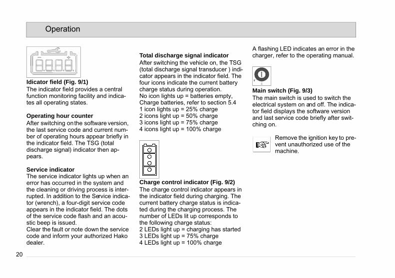
Idicator field (Fig. 9/1)The indicator field provides a central function monitoring facility and indica-tes all operating states.
Operating hour counterAfter switching on the software version, the last service code and current num-ber of operating hours appear briefly in the indicator field. The TSG (total discharge signal) indicator then ap-pears.
Service indicatorThe service indicator lights up when an error has occurred in the system and the cleaning or driving process is inter-rupted. In addition to the Service indica-tor (wrench), a four-digit service code appears in the indicator field. The dots of the service code flash and an acou-stic beep is issued.Clear the fault or note down the service code and inform your authorized Hako dealer.
Total discharge signal indicatorAfter switching the vehicle on, the TSG (total discharge signal transducer ) indi-cator appears in the indicator field. The four icons indicate the current battery charge status during operation.No icon lights up = batteries empty,Charge batteries, refer to section 5.41 icon lights up = 25% charge2 icons light up = 50% charge3 icons light up = 75% charge4 icons light up = 100% charge
Charge control indicator (Fig. 9/2)The charge control indicator appears in the indicator field during charging. The current battery charge status is indica-ted during the charging process. The number of LEDs lit up corresponds to the following charge status:2 LEDs light up = charging has started3 LEDs light up = 75% charge4 LEDs light up = 100% charge
A flashing LED indicates an error in the charger, refer to the operating manual.
Main switch (Fig. 9/3)The main switch is used to switch the electrical system on and off. The indica-tor field displays the software version and last service code briefly after swit-ching on.
Remove the ignition key to pre-vent unauthorized use of the machine.
20
Operation
Idicator field (Fig. 9/1)The indicator field provides a central function monitoring facility and indica-tes all operating states.
Operating hour counterAfter switching on the software version, the last service code and current num-ber of operating hours appear briefly in the indicator field. The TSG (total discharge signal) indicator then ap-pears.
Service indicatorThe service indicator lights up when an error has occurred in the system and the cleaning or driving process is inter-rupted. In addition to the Service indica-tor (wrench), a four-digit service code appears in the indicator field. The dots of the service code flash and an acou-stic beep is issued.Clear the fault or note down the service code and inform your authorized Hako dealer.
Total discharge signal indicatorAfter switching the vehicle on, the TSG (total discharge signal transducer ) indi-cator appears in the indicator field. The four icons indicate the current battery charge status during operation.No icon lights up = batteries empty,Charge batteries, refer to section 5.41 icon lights up = 25% charge2 icons light up = 50% charge3 icons light up = 75% charge4 icons light up = 100% charge
Charge control indicator (Fig. 9/2)The charge control indicator appears in the indicator field during charging. The current battery charge status is indica-ted during the charging process. The number of LEDs lit up corresponds to the following charge status:2 LEDs light up = charging has started3 LEDs light up = 75% charge4 LEDs light up = 100% charge
A flashing LED indicates an error in the charger, refer to the operating manual.
Main switch (Fig. 9/3)The main switch is used to switch the electrical system on and off. The indica-tor field displays the software version and last service code briefly after swit-ching on.
Remove the ignition key to pre-vent unauthorized use of the machine.

21
Operation
Dead-man's switch (Fig. 9/4)If the dead-man's switch on the bail sy-stem is released during operation, the traction drive, brush head drive and so-lution supply are switched off. The suc-tion turbine remains switched on.
Direction switch (Fig. 9/5)The direction switch is used to preselect the driving direction for the machine.Switch to front = forward driveSwitch to rear = reverse driveTo change the driving direction, bring the machine to a stop, select the new di-rection and start again.
Driving speed control (Fig. 9/6)The driving speed control is a conti-nuously adjustable knob to set the ma-chine speed.
Symbol for silence kit (option) (Fig. 9/8)The LED lights up when the silence kit function is switched on.
Symbol for tool connection (option) (Fig. 9/9)The LED lights up when the tool con-nection function is switched on.
Silence kit button (option) (Fig. 9/10)The silence kit button is used to switch low-noise operation on and off. The si-lence kit reduces the noise made by the vacuuming equipment.
Tool connection button (option) (Fig. 9/10)The tool connection button is used to switch operation of the spray and vacu-um tool on and off.

22
Operation
Solution dosage button (Fig. 9/7)The solution quantity can be adjusted during operation. The level selected ap-pears as an icon in the indicator field. To adjust the solution quantity, press the button until the required level is indi-cated. Conditions to set the solution quantity:• Main switch is switched on• Brush head is lowered• Press dead-man's switch
Solution supply on/off button (Fig. 9/12)The button serves to switch the solution supply on and off. When the brush is switched on, the last solution quantity set is automatically reactivated but this setting can be altered, however, with the solution dosage button.
Brush ejection button (Fig. 9/13)The brush can be removed for mainte-nance purposes by pressing a button.
Eject brush:Raise the brush head. Press the button for approx. 5 seconds when the brush head is raised. Brush ejection is indica-ted in the indicator field by four icons which light up successively.
After brush ejection, the top and bottom row of symbols flash alternately. The machine is not ready to operate. Switch the machine off using the main switch.
Attach brush:Switch the machine on again using the main switch. Position the brush cente-red under the raised brush head. Lower the brush head. When the brush head drive is switched on by means of the
dead-man's switch of the bail system, the brush is automatically attached.

23
Operation
3.2.2 Operating elements on the machine
1 Solution tank filling neck2 Squeegee lift lever3 Solution filter4 Solution draining hose 5 Charger power connection6 Brush head lift foot pedal7 Waste water draining hose8 Solution dosage hand valve
Hakomatic B30 only
Fig.10 Hakomatic B30
2
8
1
3
4
5
6
7

24
Operation
Solution tank filling neck (Fig. 10/ 1)The solution tank is filled through a de-tachable filling neck. The fill level can be seen through the draining hose.
Squeegee lift hand lever (Fig. 10/2)The hand lever is used to lower and rai-se the squeegee, whereby the suction turbine is switched on and off, respec-tively (Hakomatic B30 only).
Solution filter (Fig. 10/3)When the solution is fed from the soluti-on tank to the brush head, the solution is cleaned by a filter insert.
Solution draining hose (Fig. 10/4)The solution tank draining hose is used to drain the solution.
Power supply line (Fig. 10/5)The power supply line feeds power to the charger. Following completion of the charging process, insert the groun-ded plug firmly in the holder with the in-tegrated vehicle immobilizer.
Brush head lift foot pedal (Fig. 10/6)This pedal raises and lowers the brush head.
Waste water draining hose (Fig. 10/7)The waste water draining hose is used to drain of the waste water drawn up.
Solution hand valve (Fig. 10/8)In the case of the Hakomatic B30, the solution to the brush head is set by means of a hand valve. The solution quantity can be regulated between 0 l/min and 1.85 l/min.

25
Technical Data
4 Technical DataMachine length (17“/20“) cm 127/135
Machine height cm 112Machine width without squeegee (17“/20“) cm 50/56Machine width with squeegee (17“/20“) cm 78/88Working width (17“/20“) cm 43/51Squeegee width (17“/20“) cm 76/86Area coverage, theoretical (17“/20“) m²/h 1720/2040Nominal voltage V 24Power consumption, traction drive (Hakomatic B30 CL/CLH only) W 180Power consumption, aspirating engine W 410Power consumption, brush motor W 720No. of brushes Pieces 1Brush diameter (17“/20“) cm 43/51Working speed kph 3,5Solution tank Liter 45Recovery tank Liter 42Weight with batteries (power flow/traction drive) kg 178/185Weight with solution and batteries (power flow/traction drive) kg 223/230

26
Technical Data
Noise emission value Without silence kit
Withsilence kit
Sound power level (LwA) measured according to DIN EN 60335-2-72 under maximum working conditions: dB (A) 84 82The sound pressure level (LpA) (at the ear of the operator) measured according to DIN IEC 60335-2-72 under normal working conditions: dB (A) 64 61Measurement inaccuracy (KpA): dB (A) 2 2
VibrationThe weighted effective value of acceleration, measured in accordance with DIN EN ISO 5349, to which the upper parts of the body (hand-arm) are exposed under normal working conditions:
m/s² < 2.5 < 2.5

27
Maintenance and Care
5 Maintenance and CareGeneral
Before proceeding to mainte-nance and care work you are advised to read and comply with the Safety Information chapter!
Compliance with the recommended maintenance works will give you the certitude of always having a reliable machine at disposition.Daily or weekly maintenance and repair works may be executed by the driver/operator having been trained accordin-gly. Further Hako system maintenance works have to be executed by qualified personnel only. Please contact your lo-cal Hako Service Centre or Hako con-tract dealer. We cannot be held liable for damages resulting from non-comp-liance with these instructions.Please indicate the machine's serial number with any enquiry or spare part order, see paragraph 1.7 - Nameplate.
5.1 Hako System MaintenanceThe Hako System Maintenance: • guarantees reliable operability of the
Hako machines (preventive mainte-
nance)• minimizes operating costs, repair
costs and maintenance costs• ensures long service life and opera-
bility of the machine The Hako System Maintenance is structured in separate modules and de-termines specific technical works to be executed as well as the intervals for such maintenance works. For any spe-cific maintenance type, the replacement parts are determined and listed in spare part kits.Hako System Maintenance Custo-mer:To be performed by the customer in ac-cordance to the maintenance and care instructions contained in the operating instructions (daily or weekly). The dri-ver/operator will be instructed upon de-livery of the machine.Hako-System Maintenance I :(every 125 hours of operation)To be performed by qualified personnel of authorised Hako Service Centre in accordance with the machine-specific system maintenance including spare part kit.Hako-System Maintenance II:(every 250 hours of operation)
To be performed by qualified personnel of authorised Hako Service Centre in accordance with the machine-specific system maintenance including spare part kit.Hako-System Maintenance III/S:(every 500 hours of operation safety check)To be performed by qualified personnel of authorised Hako Service Centre in accordance with the machine-specific system maintenance including spare part kit. Execution of all safety-relevant inspections according to UVV-BGV-TÜV-VDE as prescribed by law.

28
Maintenance and Care
5.2 Maintenance Document
Handing over
UpgradeTest driveHanding over to the customerInstructioncarried out on:
at _________________ operating hours
Hako-System-Maintenance I125 operating hours
Workshop stamp
carried out on:
at _________________ operating hours
Hako-System-Maintenance II250 operating hours
Workshop stamp
carried out on:
at _________________ operating hours
Hako-System-Maintenance I375 operating hours
Workshop stamp
carried out on:
at _________________ operatin hours
Hako-System-Maintenance III/S500 operating hours
Workshop stamp
carried out on:
at _________________ operating hours
Hako-System-Maintenance I625 operating hours
Workshop stamp
carried out on:
at _________________ operating hours
Hako-System-Maintenance II750 operating hours
Workshop stamp
carried out on:
at _________________ operating hours
Hako-System-Maintenance I875 operating hours
Workshop stamp
carried out on:
at _________________ operatin hours
Hako-System-Maintenance III/S1000 operating hours
Workshop stamp
carried out on:
at _________________ operating hours
Hako-System-Maintenance I1125 operating hours
Workshop stamp
carried out on:
at _________________ operating hours
Hako-System-Maintenance II1250 operating hours
Workshop stamp
carried out on:
at _________________ operating hours
Hako-System-Maintenance I1375 operating hours
Workshop stamp
carried out on:
at _________________ operating hours

29
Maintenance and Care
5.3 Maintenance ScheduleHako-System Maintenance Custo-merThe daily and weekly maintenance in-tervals are to be performed by the cu-stomer/operator.
To be performedInterval
daily weekly
Fill clear water tank and proceed to chemical agent dosage oCharge batteries oCheck brush head and clean if required oCheck squeegee and clean if required oEmpty soiled water tank, clean soiled water tank and suction filter oClean tank lid sealing of the soiled water tank oCheck brush head sealing strips and replace if required oCheck brushes/pads and replace if required oClean suction hose of soiled water tank oCheck water filter and clean if required oCheck squeegee sealing strips and eventually turn round or replace oCheck clear water supply to brushes and clean if required oCheck deflector roller of brush head and replace if required oTest drive and function test o

30
Maintenance and Care
Hako-System Maintenance IThe following maintenance woks are to be performed by an authorised Hako Service workshop.
To be performedInterval
every 125 hours of operation
Check battery charger oCheck tank lid sealing of the soiled water tank and replace if required oCheck function of bailsystem and operating panel oCheck drain hose of the soiled water tank and replace if required oGrease joints at the brush lift-out oCheck wheel fixing screws and tighten (10 Nm) if required oCheck condition of tyres oGrease joints at the squeegee holder oTest drive and function test o

31
Maintenance and Care
Hako-System Maintenance IIThe following maintenance woks are to be performed by an authorised Hako Service workshop.
To be performedInterval
every 250 hours of operation
Perform maintenance works according to Hako-System Maintenance I oInspect steering rollers for tread damages and bearing slackness and replace if required
o
Check function of water pump and replace if required oCheck drain hose of the soiled water tank and replace if required oCheck deflector roller of the brush head and replace if required oCheck suction hose for tight fitting and damages and replace if required oCheck supporting wheel of the squeegee and replace if required oTest drive and function test o

32
Maintenance and Care
Hako-System Maintenance III/S (Safety check)The following maintenance woks are to be performed by an authorised Hako Service workshop at least once yearly.
To be performedInterval
every 500 hours of operation
Perform maintenance works according to Hako-System Maintenance II oCheck drive protection of the charger oCheck function of suction turbine and replace if required (replace at the latest after 1000 operating hours)
o
Check brake of the travel drive motor (Hakomatic B30 CL/CLH only) oClean travel drive motor (Hakomatic B30 CL/CLH only) from carbon dust and check carbon brushes for smooth operation and wearing and replace carbon brushes if required
o
Clean brush motors from carbon dust and check carbon brushes for smooth opera-tion and wearing and replace carbon brushes if required (replace at the latest after 1000 operating hours)
o
Test drive and function test o

33
Maintenance and Care
5.4 Battery system1 Total discharge signal indicator2 Charge control indicator3 Charger4 Charger power cable 5 Holder with machine immobilizer6 Battery terminals7 Batteries8 Recovery tank9 Connection plan
Batteries may only be handled and changed by properly skilled maintenance person-nel.
During operation, the TSG indi-cator (Fig. 11/1) displays the charge status of the batteries. The battery icon flashes when the batteries are discharged. The machine functions are re-stricted. Charge the batteries immediately!If the grounded plug is not in-serted in the holder (Fig. 11/5) after the charging process, the integrated machine immobili-zer prevents the machine being started up!
Fig.11 Hakomatic B30
4
3
1 2
6
5 9
78

34
Maintenance and Care
5.4.1 Charging batteriesThe batteries are charged using the in-tegrated battery charger (Fig. 11/3). The charger is connected by means of the power cable (Fig. 11/4) with groun-ded plug. We recommended charging the battery when at least one bar of the total discharge signal transducer indica-tor has gone out after operating the ma-chine. The charge control indicator (Fig. 11/2) indicates the charge status of the batteries during the charging process. Pay attention to the information in the operating manuals supplied with the charger and the battery manufacturer.
Before starting the vehicle up for the first time, the batteries to be used must be fully charged, properly, by imple-menting the initial battery char-ge routine. Hako assumes no liability for damage to the battery caused by a fault when the battery is charged for the first time.Ensure sufficient ventilation in the charging area when char-ging the batteries. – Risk of explosion.
5.4.2 Total discharge signal transducer (TSG)
The machine is equipped with a total discharge signal transducer (Fig. 11/1) to prevent the batteries being fully discharged. The total discharge signal transducer is integrated in the electro-nics. If other batteries are used, the to-tal discharge signal transducer must be adjusted.
The total discharge signal transducer may only be adju-sted by an authorized Hako service center.
5.4.3 Servicing the driving batteriesFor information on servicing driving bat-teries, refer to operating manual 88-60-2556.
5.4.4 Removing the batteries1. Park the machine on a level area of
floor.2. Switch the machine off at the main
switch.3. Open the empty recovery tank
(Fig. 11/8).4. Disconnect the battery terminal
(Fig. 11/6).5. Disconnect the battery connection
cable and remove the batteries.
5.4.5 Inserting the batteries
Due to a change in the center of gravity, only approved batte-ries may be installed at the in-tended position.
1. Switch the machine off at the main switch.
2. Open the empty recovery tank (Fig. 11/8).
3. Position the batteries in the battery tray in accordance with the figure.
4. Connect the battery poles in accor-dance with the connection plan (Fig. 11/9) to the connection cables enclosed in the accessories kit. Pay attention they are firmly fixed and grease the poles.
5.4.6 Disposing of batteriesUsed batteries with the recycling sym-bol contain reusable commodities. In accordance with symbol with the crossed out bin, these batteries must not be disposed of in domestic waste. Return and recycling must be agreed on with Hako's authorized dealer in ac-cordance with § 8 BattV (Battery Direc-tive)!

35
Maintenance and Care
5.5 Solution tank
1 Solution tank2 Marking3 Fill level hose4 Solution filter5 Tank cap
Fig.12 Hakomatic B30
5
31
2
4
35
Maintenance and Care
5.5 Solution tank
1 Solution tank2 Marking3 Fill level hose4 Solution filter5 Tank cap
Fig.12 Hakomatic B30
5
31
2
4

36
Maintenance and Care
5.5.1 Filling the solution tankFill the solution tank (Fig. 12/1) before starting work or as necessary. Park the vehicle on a level floor area.Open the tank cap (Fig. 12/5) and fill the solution tank up to the maximum mar-king (1/1)(Fig. 12/2).
5.5.2 Emptying the solution tankPark the machine so that the fill level hose (Fig. 12/3) is above a drain in the floor. Remove the fill level hose from the holder and remove the cover.
5.5.3 Cleaning the fresh water filterCheck the solution filter (Fig. 12/4) wee-kly and clean or replace it as necessary.
Only clean the solution filter when the tank is empty.
1. Empty the solution tank (Fig. 12/1), see paragraph 5.5.2.
2. Screw the filter cap off.3. Remove the filter element in the filter
housing to clean it. Replace it with a new one, if necessary.
4. Replace the filter element and filter cap.
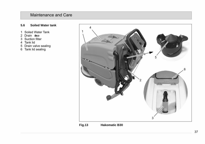
37
Maintenance and Care
5.6 Soiled Water tank
1 Soiled Water Tank2 Drain hose3 Suction filter4 Tank lid5 Drain valve sealing6 Tank lid sealing
Fig.13 Hakomatic B30
1
14
3
5
2
6
37
Maintenance and Care
5.6 Soiled Water tank
1 Soiled Water Tank2 Drain hose3 Suction filter4 Tank lid5 Drain valve sealing6 Tank lid sealing
Fig.13 Hakomatic B30
1
14
3
5
2
6
38
Maintenance and Care
5.6.1 Empty Soiled Water TankClean soiled water tank (Fig. 13/1) at daily intervals, as required or upon acoustic signal (increased suction turbi-ne speed).1. Take machine to appropriate place
for discharge. 2. Park machine such that drain hose
attains drain aperture in the floor.3. Switch off machine.
Observe the legal provisions and the local regulations for disposal of detergents!
4. Take drain hose (Fig. 13/2) from hol-der and empty soiled water tank completely.
5.6.2 Clean Soiled Water TankClean soiled water tank (Fig. 13/1) at daily intervals or as required.1. Empty soiled water tank, see para-
graph 5.6.1.2. Open tank lid (Fig. 13/4) of the soiled
water tank.3. Take drain hose (Fig. 13/2) from hol-
der and empty soiled water tank completely.
4. Remove remaining dirt by rinsing with clear water.
5. Rinse drain hose as well.
5.6.3 Clean Suction FilterCheck suction filter (Fig. 13/3) for func-tion at daily intervals and clean if re-quired. The suction filter is clipped and can be easily removed.
5.6.4 Checking the Draining valve seal
Check the functionality of the draining valve (Fig. 13/5) daily and change it af-ter 125 operating hours at the latest. Remove the draining hose from the hol-der. Turn the draining valve 90° and pi-vot away from the draining hose. Grease the new seal and pin with Moly-kote.
5.6.5 Checking the Tank lid sealCheck the functionality of the seal in the tank cap (Fig. 13/6) daily and change it after 125 operating hours at the latest.
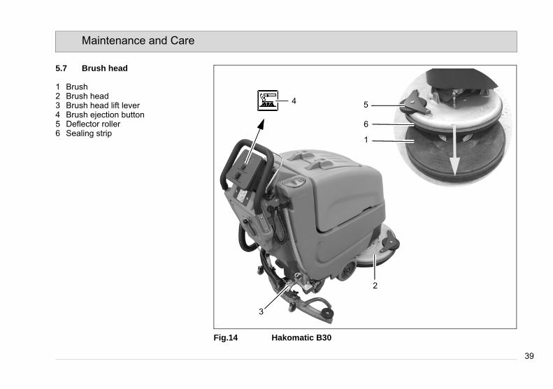
39
Maintenance and Care
5.7 Brush head
1 Brush2 Brush head3 Brush head lift lever4 Brush ejection button5 Deflector roller 6 Sealing strip
Fig.14 Hakomatic B30
3
2
5
6
1
4
39
Maintenance and Care
5.7 Brush head
1 Brush2 Brush head3 Brush head lift lever4 Brush ejection button5 Deflector roller 6 Sealing strip
Fig.14 Hakomatic B30
3
2
5
6
1
4

40
Maintenance and Care
5.7.1 Changing the brushesCheck the brushes (Fig. 14/1) in the brush head (Fig. 14/2) weekly for signs of wear. In the case of wear to a brush length of 1.5 cm, the brushes must be changed.
Eject brush:Raise the brush head using the lever (Fig. 14/3). Press the button (Fig. 14/4) for approx. 5 seconds when the brush head is raised. Brush ejection is indica-ted in the indicator field by four icons which light up successively.
After brush ejection, the top and bottom row of symbols flash alternately. The machine is not ready to operate. Switch the machine off using the main switch.
Attach brush:Switch the machine on again using the main switch. Position the brush cente-red under the raised brush head. Lower
the brush head. When the brush head drive is switched on by means of the dead-man's switch of the bail system, the brush is automatically attached.
5.7.2 Changing the deflector roller Check the deflector roller (Fig. 14/5) weekly and change it as necessary.
5.7.3 Changing the sealing stripCheck the sealing strip (Fig. 14/6) wee-kly and change it as necessary. To do this, loosen the fastening device and re-move the sealing strip. Installation is carried out in the reverse sequence.

41
Maintenance and Care
5.8 Squeegee
1 Squeegee2 Star-shaped knob3 Adjusting bolt for angle adjustment4 Suction hose5 Fastening device6 Washers for height adjustment
Fig.15
5.8.1 Cleaning the squeegeeCheck the squeegee (Fig. 15/1) daily and clean it as necessary. To clean the squeegee raise it, discon-nect the suction hose (Fig. 15/4), loo-sen the two star-shaped knobs (Fig. 15/2) and remove the squeegee.
5.8.2 Changing the sealing stripsCheck the inner and outer sealing strips on the squeegee (Fig. 15/1) weekly for signs of wear. The sealing strips can be turned four times (90°) and reused.1. Raise the squeegee.2. Disconnect the suction hose, loosen
the two star-shaped knobs and re-move the squeegee.
3. Loosen the fastening device (Fig. 15/5) and remove the outer sealing strip. Turn the sealing strip or replace it, as necessary. Change the inner sealing strip in the same way.
21 253 4 66

42
Maintenance and Care
5.8.3 Adjusting the sealing stripsAngle adjustmentThe angle adjustment is decisive in controlling whether the squeegee's sealing strips lie evenly on the floor.1. Park the machine on a level surface
and lower the squeegee.2. Loosen the counternut on the adju-
sting bolt (Fig. 15/3) and adjust the squeegee with the adjusting bolt until the ends of the sealing strips just make contact with the floor.Fig. ATurn the adjusting bolt clockwise: Di-stance between sealing strip and floor is decreased in the middle.Fig. BTurn the adjusting bolt counterclock-wise: Distance between sealing strip and floor is increased in the middle.
3. Switch the machine on and check the suction pattern. When driving, the sealing strips must make as even a contact as possible all around (center and outer sides).
4. Tighten the counternut on the adju-sting bolt at 7 Nm.
Fig.16
B
A

43
Maintenance and Care
Height adjustmentThe height adjustment is set to 3 mm at the factory. If streaks appear despite an optimum angle adjustment, the di-stance of the rollers to the floor must be adjusted by changing the number of washers on the holder.
In the case of very smooth floors, e.g. varnished floors, linoleum etc.:Number of washers = 2. This corre-sponds to a distance of approx. 2 mm to the floor.
In the case of very uneven floors, e.g. badly laid tiles (water does not run off):Number of washers = 4. This corre-sponds to a distance of approx. 4 mm to the floor.
Fig.17
3 mm
2 mm 4 mm

44
Maintenance and Care
44
Maintenance and Care

Hakomatic B 30Changes Due to Machine Directive 2006/42/EC Clean ahead
PrefaceModified text in paragraph Preface:Before using the equipment for the first time, read this original manual thor-oughly, act according to the information contained and keep it in a safe place for future reference or subsequent owners.Intended useModified text in paragraph Intended Use:Based on the conception, design and construction of the model introduced onto the market by us, the machine complies with the applicable basic safe-ty and health requirements stipulated in the EC Directive (refer to Declaration of Conformity). This declaration is no long-er considered valid in the event of mod-ifications to the machine not authorized by us. The manufacturer is not deemed liable for any damage resulting from un-authorized modifications to the ma-chine.General safety informationThe machine may be used only for operation on plane areas with a maxi-mum inclination of up to 2 %.
DisposalNew text in Chapter Introduction:Render the machine inoperable. It must not represent a potential source of dan-ger for children.Dispose of the device according to the applicable local regulations. For further information on handling and recycling, please contact your authorized Hako dealer where you purchased the de-vice.Used batteries with the recycling sym-bol contain reusable commodities. The heavy metals contained simultaneously represent a serious risk to health and to the environment. Never open batteries or damage them. Never touch, inhale or swallow any material inside batteries. Health hazard! Never allow batteries to pollute the environment. Risk of con-taminating the ground and water! In ac-cordance with the symbol with the crossed out bin, these batteries must not be disposed of in domestic waste. The return and recycling of old batteries must be agreed on with your authorized Hako dealer in accordance with the Bat-tery Law § 6 and § 8 (BattG)
Noise emission valueThe sound pressure level (LpA) (at the ear of the operator) measured accord-ing to DIN IEC 60335-2-72 under nor-mal working conditions: 64 dB (A)Measurement inaccuracy (KpA): 2 dB (A)Sound power level (LwAd) measured according to DIN EN 60335-2-72 under maximum working conditions: 84 dB (A)VibrationThe weighted effective value of acceler-ation, measured in accordance with ISO 5349-1, to which the upper parts of the body (hand-arm) are exposed under normal working conditions: < 2,5 m/s²The weighted effective value of acceler-ation, measured in accordance with ISO 2631-1, to which the upper parts of the body (feet-seat) are exposed under normal working conditions: < 0,5 m/s²

Hako-Werke GmbHHamburger Straße 209-239D-23843 Bad Oldesloe
declares that the products
Hakomatic B 30, Typ 7715.20Hakomatic B 30 CL, Typ 7715.40
to which this declaration relates, con-form to the relevant provisions of the safety and health requirements stipulat-ed in EC Directive 2006/42/EC and is in accordance with 2004/108/EC.
Reference was made to the following standards and/or norms and/or techni-cal specifications to ensure proper im-plementation of the safety and health requirements in the EC Directive:
EN 60335-2-72EN 55012EN 61000-6-2
Bad Oldesloe, 27.10.2010
Dr. Rainer BavendiekDirector R&D
Name of the authorized person who compiles technical documents for Hako:
Ludger Lüttel
EC Declaration of Conformity (corresponds to EC Directive 2006/42/EC)


Spitzentechnik für einesaubere und schönere UmweltSuperior technology for a cleaner and better environment
Hako-Werke GmbH · Stammwerk und Hauptverwaltung · HeadquartersHamburger Str. 209-239 · D-23843 Bad Oldesloe · (04531) 806-0 · Fax (04531) 806-338
88-1
0-28
50/1
1-20
10 •
Prin
ted
in G
erm
any
Spitzentechnik für einesaubere und schönere UmweltSuperior technology for a cleaner and better environment
Hako-Werke GmbH · Stammwerk und Hauptverwaltung · HeadquarterHamburger Str. 209-239 · D-23843 Bad Oldesloe · (04531) 806-0 · Fax (04531) 806-338
88-6
0-28
50/1
1-20
10 •
Prin
ted
in G
erm
any