Embed Size (px)
Citation preview

Table of Contents1.0 Introduction
2.0 Assembly Drawing
3.0 Installation
4.0 Communications
5.0 Certifications and Electromagnetic Compatibility Testing
Universal Resistance Temperature Detector (URTD) Module II
Instruction Leaflet IL02602013E Rev D Effective September 2013

1.0 Introduction
The Universal RTD Module II (URTDII) is an electronic resistance-temperature detector accessory for the devices shown in Table 1:
Table 1, Applicable Devices
Legacy Expanded
MP3000 EMR3000
MP4000 EMR4000
FP6000 EMR5000
IQ1000II ETR4000
ETR5000
EGR4000
EGR5000
The URTDII can be used to monitor as many as 12 RTD inputs, These inputs fall into four groups that consist of: six motor windings, two motor bearings, two load bearings, and two auxiliary RTDs.
The URTDII can be programmed to accept any of the follow-ing types of RTD inputs:
• 100 ohm platinum
• 100 ohm nickel
• 120 ohm nickel
• 10 ohm copper
The RTD type can be selected for each of the four RTD groups. For example, The motor winding RTD inputs can be programmed for 10 ohm copper and the motor bearing RTD inputs can be programmed for 120 ohm nickel.
The URTDII can transmit its information to a protective device using a fiber optic link. It can be mounted remotely up to 122 meters (400 feet) from the protective device when using the fiber optic link.
The URTDII can also be used as a stand-alone device that communicates on a Modbus network. A bidirectional RS485 port is provided on the bottom of the unit.
2
IL02602013E Rev D Universal Resistance Temperature September 2013 Detector (URTD) Module II
IL02602013E Rev D - September 2013 - www.eaton.com
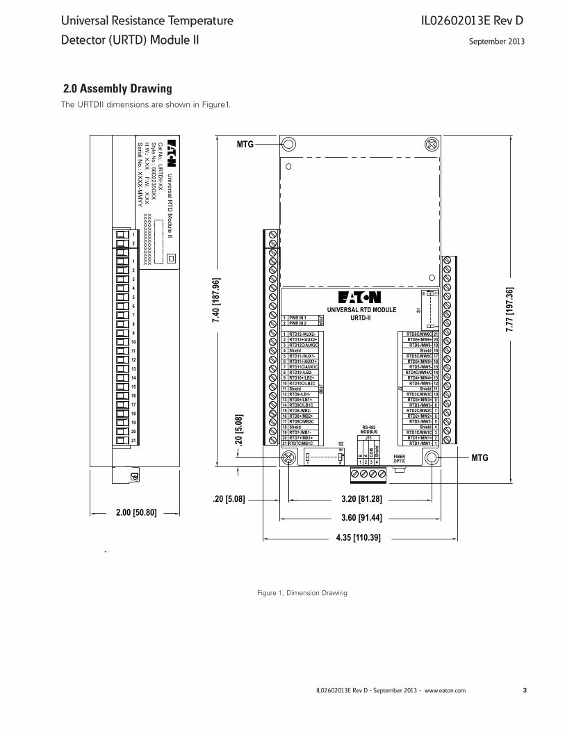
Figure 1, Dimension Drawing
2.0 Assembly Drawing The URTDII dimensions are shown in Figure1.
J2
J10B
RTD7C/MB1C21RTD7+/MB1+20RTD7-/MB1-19Shield18RTD8C/MB2C17RTD8+/MB2+16RTD8-/MB2-15RTD9C/LB1C14RTD9+/LB1+13RTD9-/LB1-12Shield11RTD10C/LB2C10RTD10+/LB2+9RTD10-/LB2-8RTD11C/AUX1C7RTD11+/AUX1+6RTD11-/AUX1-5Shield4RTD12C/AUX2C3RTD12+/AUX2+RTD12-/AUX2-
21
PWR IN 2PWR IN 1
21
123456789101112131415161718192021
RS-485MODBUS
FIBEROPTIC
S2
S1UNIVERSAL RTD MODULEURTD-II
B A COM
Shiel
d
1 2 3 4
J11
0N
112
0N
1 8
J10A
RTD6C/MW6CRTD6+/MW6+RTD6-/MW6-
ShieldRTD5C/MW5CRTD5+/MW5+RTD5-/MW5-
RTD4C/MW4/CRTD4+/MW4+RTD4-/MW4-
ShieldRTD3C/MW3CRTD3+/MW3+RTD3-/MW3-
RTD2C/MW2CRTD2+/MW2+RTD2-/MW2-
ShieldRTD1C/MW1CRTD1+/MW1+RTD1-/MW1-
7.40 [
187.9
6]
.20 [5
.08]
3.60 [91.44]
3.20 [81.28].20 [5.08]7.7
7 [19
7.36]
Style N
o.: C
at No.:
H.W
.: S
erial No.: U
niversal RTD
Module II
66D2235G
XX
X.X
XX
XX
X-M
MY
Y
UR
TDII-X
X
XX
XX
XX
XX
XX
XX
XX
XX
XX
XX
XX
XX
XX
XX
XX
XX
XX
XX
F.W.: X
.XX
4.35 [110.39]
2.00 [50.80]
MTG
MTG
21
20
19
18
17
16
15
14
13
12
11
10
9
8
7
6
5
4
3
2
1
2
1
3
Universal Resistance Temperature IL02602013E Rev D Detector (URTD) Module II September 2013
IL02602013E Rev D - September 2013 - www.eaton.com
3.0 Installation
WARNINGHAZARDOUS CONDITIONS MAY RESULT IF THIS PROD-UCT IS NOT USED FOR INTENDED PURPOSES. THE DEVICE WILL NOT OPERATE PROPERLY IF USED IN A MANNER NOT SPECIFIED BY THE MANUFACTURER.
This industrial type control should be installed, operated and maintained by adequately trained personnel. The instruc-tions in this document do not cover all details, variations, or combinations of the equipment, its storage, delivery, installation, check-out, safe operation, or maintenance. Care must be exercised to comply with local, state, and national regulations, as well as safety practices, for this class of equipment.
3.1 Mounting
The URTDII can be mounted to the back of a MP3000 or MP4000 using the supplied bracket and hardware. The URTDII can also be mounted as a stand-alone device at a convenient location using the mounting dimensions pro-vided in Figure 1.
Device must be located where hazardous terminals are not accessible.
3.2 Control Power
Connect the power supply terminals (labeled J10A) on the URTDII to a suitable power source. Refer to Table 4 for con-nection guidelines. The terminal blocks used in this device are suitable for field wiring, No. 22-14 AWG, solid or strand-ed copper wire conductor, tightening torque 7 in. lb.
The power supply wiring should be fused or put on a break-er sized to protect the wire.
A circuit breaker shall be included in the building installation.
The circuit breaker shall be in close proximity to the equip-ment and within easy reach of the operator.
The circuit breaker shall be marked as the disconnecting device for the equipment.
Product shall be installed in accordance with local codes.
Table 3, IEC Symbol Description
IEC Symbol Description
Both Direct and Alternating Current
Direct Current
Equipment protected throughout by DOUBLE INSULATION or REINFORCED INSULATION
To Power Supply
Terminal Block Power (J10A)
AC Power Supply DC Power Supply
1 Line Positive
2 Neutral Negative
Table 4, URTDII Power Connections
Table 2, Specifications
Specifications URTDII-01 URTDII-02
Input Power Requirements 48-240 VAC / 48-250 VDC
24-48 VDC
Frequency 50/60 Hz or DC DC
Power Consumption 3.5W 1 W
Operating Temperature -20° to 55° C (-4° to 131° F)
-20° to 55° C (-4° to 131° F)
Storage Temperature -40° to 85° C (-40° to 185° F)
-40° to 85° C (-40° to 185° F)
Humidity 0 to 95% R.H. Non-condensing
0 to 95% R.H. Non-condensing
Altitude 2000 Meters 2000 Meters
Pollution Degree 2 2
Installation Category I I
4
IL02602013E Rev D Universal Resistance Temperature September 2013 Detector (URTD) Module II
IL02602013E Rev D - September 2013 - www.eaton.com

3.3 URTDII Wiring
Each RTD must be wired to the URTDII, as shown in Figures 2 and 3. The following guidelines must be observed:
Use only one type of RTD (10 ohm copper, 100 ohm nickel, 100 ohm platinum, or 120 ohm nickel) for each RTD group: motor winding, motor bearing, load bearing and auxiliary. For example, you cannot monitor one 10 ohm copper motor bearing RTD and one 120 ohm nickel motor bearing RTD. However, you can monitor 10 ohm copper winding RTDs and 100 ohm nickel motor bearing RTDs.
1. Use #18 three-conductor, stranded, twisted, copper wire to connect the RTD to the URTDII.
2. Connect three conductors from the RTD to the URTDII. (Two return wires must be connected together). Where the motor has only two leads from the RTD, connect two of the three conductors together at one of the leads. Make this connection as close to the RTD as possible (see Figure 3). If only two conductors are connected between the RTD and the URTDII, the device will not operate correctly.
3. Connect the cable shield and drain wires to the appropri-ate terminal on the URTDII. At the opposite end, cut the shield and drain wire short and tape them, to prevent short circuits.
otee:N Do not connect this wiring at the RTD end.
4. If one or more of the 12 possible RTD inputs on the module are not used, they can be left open or jumpered out without affecting the operation of the protective devices.
1 -2 +3 C4 S5 -6 +7 C8 -9 +10 C11 S12 -13 +14 C15 -16 +17 C18 S19 -20 +21 C
212019181716151413121110987654321
C+-SC+-C+-SC+-C+-SC+-
J10B J2Auxiliary
LoadBearings
MotorBearings
MotorWindings
RTD
RTD
RTD
RTD
RTD
RTD
RTD
RTD
RTD
RTD
RTD
RTD
UniversalRTD Module II
WireShield/Drain
TerminalsMotor
USE TAPE TO INSULATEDO NOT CONNECT CABLE'S SHIELD WIRE AT THIS END!
TerminalsMotor
WireShield/Drain
WireShield/Drain
WireShield/Drain
WireShield/Drain
WireShield/Drain
NC
otee:N
1. Each shielded cable conductor must be connected on the URTDII as shown.
2. Use of three-lead RTDs is recommended.
3. RTDs must not be grounded at the motor, and no common connections between RTDs should be made at the motor.
4. A suitable earth ground should be connected to J10B-4, J10B-11, J-10B-18, J2-4, J2-11, or J2-18. It is recommended that a ground connection is made to both sides of the unit.
Figure 2, RTD Wiring (Three-Lead Type)
5
Universal Resistance Temperature IL02602013E Rev D Detector (URTD) Module II September 2013
IL02602013E Rev D - September 2013 - www.eaton.com

4321
SC+- RTD
WireShield/Drain
RTD WIRING (THREE-LEAD TYPE)
4321
SC+- RTD
USE TAPE TO INSULATECABLE'S SHIELD WIRE AT THIS END!
RTD WIRING (TWO-LEAD TYPE)
TerminalsMotorDO NOT CONNECT
TerminalsMotor
USE TAPE TO INSULATECABLE'S SHIELD WIRE AT THIS END!
DO NOT CONNECT
WireShield/Drain
Notes:
1. Connect cable shield at URTDII terminals only. Cut shield short at motor end and use shrink tubing or electrical tape to insulate.
2. RTDs must not be grounded at the motor and no common connections between individual RTDs should be made at the motor.
Figure 3, Wiring to URTDII
6
IL02602013E Rev D Universal Resistance Temperature September 2013 Detector (URTD) Module II
IL02602013E Rev D - September 2013 - www.eaton.com

Figure 4, DIP Switches S2 Figure 5, DIP Switch Positions
A. Motor Winding RTD C. Load Bearing RTD
RTD Type Switch Settings RTD Type Switch Settings
1 2 5 6
100 Ohm Platinum ON ON 100 Ohm Platinum ON ON
100 Ohm Nickel OFF ON 100 Ohm Nickel OFF ON
120 Ohm Nickel ON OFF 120 Ohm Nickel ON OFF
10 Ohm Copper OFF OFF 10 Ohm Copper OFF OFF
B. Motor Bearing RTD D. Auxiliary RTD
RTD Type Switch Settings RTD Type Switch Settings
3 4 7 8
100 Ohm Platinum ON ON 100 Ohm Platinum ON ON
100 Ohm Nickel OFF ON 100 Ohm Nickel OFF ON
120 Ohm Nickel ON OFF 120 Ohm Nickel ON OFF
10 Ohm Copper OFF OFF 10 Ohm Copper OFF OFF
Table 5, DIP Switch Settings
AuxiliaryRTD Type
Load BearingRTD Type
Motor BearingRTD Type
Motor WindngRTD Type
1 2 3 4 5 6 7 8
ON
ON
OFF
3.4 Programming the Universal RTD Module II
The URTDII must be programmed for the type of RTDs that are being monitored. A DIP switch assembly on the module enables programming for the specific application. Figure 4 shows the arrangement of the DIP switches in the assem-bly. They provide four selection groupings that you must set during installation.
As Figure 4 shows, the DIP switch assembly contains eight two-position slide switches that are set in combination. Each switch is set to ON or OFF by sliding it back and forth.
When facing the DIP switches, slide them:
• Toward the FRONT of the unit for the ON position, and
• Toward the REAR of the unit for the OFF position.
Observe the ON and OFF designations on the DIP switches shown in Figures 4 and 5.
otee:N Always look for the ON and OFF designations on the hardware or printed circuit board to be sure you are setting the switches correctly.
DIP switch ON and OFF settings are shown in Table 5. .
7
Universal Resistance Temperature IL02602013E Rev D Detector (URTD) Module II September 2013
IL02602013E Rev D - September 2013 - www.eaton.com

BA
1A
H1
2B
H
H1
2C
H
H
C 22H
G
1G
2524123456789
10
2322212019
1718
16
111213
1514
CONTROL POWERTRANSFORMER
NON-CURRENTCARRYING GND.
120 VAC
MP-XXXX
CUSTOMER REMOTEINPUT CONTACTS
OR PUSHBUTTONSOPTICAL FIBER FOR URTD
COMMUNICATIONS TO MP-XXXX(PREFERRED METHOD)
FIBEROPTIC
UNIVERSAL RTD MODULEURTD-II
PWR IN 2PWR IN 1
21
J10A
FUSE
Figure 6, Fiber Optic Connection between MP-4000 and Universal RTD Module II
Table 6, Fiber Optic Cabling
Length (Meters) Eaton Catalog Number
H-P Style Number
1 MPFO-1 HBFR-ELS-001 orHBFR-RLS-001
5 MPFO-5 HBFR-ELS-005 orHBFR-RLS-005-
10 MPFO-10 HBFR-ELS-010- orHBFR-RLS-010
25 MPFO-25 HBFR-ELS-025
50 MPFO-50 HBFR-ELS-050
75 MPFO-75 HBFR-ELS-075
76 MPFO-76 HBFR-ELS-076
100 MPFO-100 HBFR-ELS-100
120 MPFO-120 HBFR-ELS-102R
Uncut Fiber Not Applicable HBFR-EUS (length)
3.5 Protective Device Connections
The URTDII can be connected to a protective device using fiber optic cable. The fiber optic cable may be no longer than 122 meters (400 feet) in length. This cable is available from Eaton using style numbers MPFO-xxx, or from Hewlett-Packard using style number HFBR-ELS-xxx, where xxx is the length of the cable in meters. This is plastic fiber optic cable that has connectors already attached at each end. Equivalent cable and connectors may be used. Cabling refer-ence numbers are shown in Table 6.
Address Dipsw1 Dipsw2 Dipsw3 Dipsw4 Dipsw5 Dipsw6 Dipsw7 Dipsw8
0 OFF OFF OFF OFF OFF OFF OFF OFF
1 OFF OFF OFF OFF OFF OFF OFF ON
2 OFF OFF OFF OFF OFF OFF ON OFF
...
254 ON ON ON ON ON ON ON OFF
255 ON ON ON ON ON ON ON ON
3.6 Wire Routing
Wire routing is divided into two types: High voltage (440 Vac and higher) and low voltage (120 Vac and DC signals). The control and the RTD wiring are low voltage lines. Maintain at least 45 to 60 cm (1.5 to 2 feet) between high voltage and low voltage conductors. Never route high voltage and low voltage lines in the same raceway.
otee:N If a fiber optic link is used, run the optic cable in the same cable tray as high voltage conductors.
8
IL02602013E Rev D Universal Resistance Temperature September 2013 Detector (URTD) Module II
IL02602013E Rev D - September 2013 - www.eaton.com

4.0 COMMUNICATIONS
4.1 Fiber Optic Settings
A set of dip switches (S1) is located on the side of the mod-ule. Dipswitch 10 is used to select the data output format of the fiber optic port. Many products in the field today are connected to the existing URTD module. This module supports 11 RTDs providing only one Auxiliary RTD to the user. To minimize the effort of replacing an existing module with a URTDII module, dipswitch 10 selects a legacy mode that provides data in the same format as the existing URTD module. Expanded mode adds the 2nd Aux RTD, case tem-perature and hottest RTDs from each group of RTDs. Table 7 shows the selection of this switch:
Table 7, Dip Switch Settings
Dipsw10 Mode
OFF 11 RTDs (Legacy Mode)
ON 12 RTDs, Case, Hottest (Expanded)
4.2 Modbus
4.2.1 General Modbus Description The URTDII can also be used as a stand-alone device that communicates on a Modbus network. A bidirectional RS485 port is provided on the bottom of the unit. The following describes the configuration of the Modbus parameters.
Physical settings:
Data Bits: 8
Parity: None
Stop Bits: 1
Flow Control: None
4.2.2 Addressing
A set of dip switches (S1) is located on the side of the mod-ule. See Figure 7. These switches set the Modbus address/configuration. Dipswitches 1 to 8 represent the binary address of the URTDII. Dipswitch 1 is the most significant address bit and dipswitch 8 is the least significant bit. Table 8 shows an abbreviated example of the addressing. Valid addresses range from 1 to 254.
Observe the ON and OFF designations on the DIP switches shown in Figures 7 and 8.
See notes below about reserved addresses.
otee:N Address 00 is a broadcast address and should not be used in a typical Modbus system. If this address is selected it will put the URTDII module in a mode provided exclusively for IMR systems. Please refer to IMR Documentation for further information.
otee:N Address 255 is a reserved address. Normal Modbus commands will not be interpreted correctly while the unit is set to this address. In this mode the URTDII should not be connected to a network because the network protocol is not being handled. The URTDII will respond to any message it received with a mini-mum of a prompt character potentially disrupting any other communications on the network.
Table 8, Modbus Address Selection Settings
Address Dipsw1 Dipsw2 Dipsw3 Dipsw4 Dipsw5 Dipsw6 Dipsw7 Dipsw8
0 OFF OFF OFF OFF OFF OFF OFF OFF
1 OFF OFF OFF OFF OFF OFF OFF ON
2 OFF OFF OFF OFF OFF OFF ON OFF
...
254 ON ON ON ON ON ON ON OFF
255 ON ON ON ON ON ON ON ON
9
Universal Resistance Temperature IL02602013E Rev D Detector (URTD) Module II September 2013
IL02602013E Rev D - September 2013 - www.eaton.com

Figure 7, DIP Switches (S1) Figure 8, DIP Switch Positions
4.2.3 Baud Rates Dipswitches 11 and 12 of dipswitch S1 (accessed on the side of the URTDII) set the Modbus baud rate. Table 9 shows the setting definitions:
Table 9, Baud Rate Selection Settings
Baud Rate Dipsw11 Dipsw12
9600 Baud OFF OFF
19200 Baud OFF ON
38400 Baud ON OFF
115200 Baud ON ON
4.2.4 Register MapTable 10 shows the addresses and data values contained in each application category with a base address of 0x00.
Actual Value Objects
Units No. of Reg.
Register Number(Decimal)
Register Number (Hexadecimal)
Category Name IEEE Float Fixed Point IEEE Float Fixed Point Fixed PointScale Factor
Fixed PointSign Factor
Product ID Product ID 2 404718 406254 126E 186E 1 Signed
Motor winding 1 °C 2 404740 406276 1284 1884 1 Signed
Motor winding 2 °C 2 404742 406278 1286 1886 1 Signed
Motor winding 3 °C 2 404744 406280 1288 1888 1 Signed
Motor winding 4 °C 2 404746 406282 128A 188A 1 Signed
Motor winding 5 °C 2 404748 406284 128C 188C 1 Signed
Temperature Motor winding 6 °C 2 404750 406286 128E 188E 1 Signed
Motor bearing 1 °C 2 404752 406288 1290 1890 1 Signed
Motor bearing 2 °C 2 404754 406290 1292 1892 1 Signed
Load bearing 1 °C 2 404756 406292 1294 1894 1 Signed
Load bearing 2 °C 2 404758 406294 1296 1896 1 Signed
Auxiliary 1 °C 2 404760 406296 1298 1898 1 Signed
Auxiliary 2 °C 2 404762 406298 129A 189A 1 Signed
Case °C 2 404764 406300 129C 189C 1 Signed
Table 10, Modbus Register Map
ModbusAddress
1 2 3 4 5 6 7 8
ON
9 10 11 12
ModbusBaud Rate
Legacy/ExpandedMode
ON
OFFNot Used
10
IL02602013E Rev D Universal Resistance Temperature September 2013 Detector (URTD) Module II
IL02602013E Rev D - September 2013 - www.eaton.com

5.0 CERTIFICATIONS AND ELECTROMAGNETIC COMPATABILITYCERTIFICATIONSe:
ISO: Manufactured under an ISO9001 Registered Program
UL: Recognized File Number E62791
USR - UL508, Seventeenth edition, April 15, 2010
CNR - CAN/CSA C22.2 No. 14-10, Eleventh edition, February 2010
CSA: Recognized File Number LR43556
CE: IEC61010-1
ELECTROMAGNETIC COMPATIBILITY TESTING
Emissions
EN61000-3-2 (2006) - Harmonics
EN61000-3-3 (2008) - Flicker
EN61000-6-4 (2007) - Radiated and Conducted Emissions
FCC Part 15 Subpart B (2010) - Radiated and Conducted Emissions
Immunity
ANSI/IEEE C37.90.1 (2002) - EFT
ANSI/IEEE C37.90.2 (2004) - Radiated RF
EN61000-6-2 (2005)
EN61000-4-2 ESD
EN61000-4-3 Radiated RF
EN61000-4-4 EFT
EN61000-4-5 Surge
EN61000-4-6 Conducted RF
EN61000-4-8 Power Frequency Magnetic Fields
EN61000-4-11 Voltage Dips and Interruptions
11
Universal Resistance Temperature IL02602013E Rev D Detector (URTD) Module II September 2013
IL02602013E Rev D - September 2013 - www.eaton.com

Eaton1000 Eaton BoulevardCleveland, OH 44122United States877-ETN-CARE (877-386-2273)Eaton.com
© 2013 EatonAll Rights ReservedPrinted in USAPublication No. IL02602013E Rev DStyle No. 66A2451H02September 2013
Eaton is a registered trademark.
All other trademarks are property of their respective owners.
IL0602013E Rev C Universal Resistance Temperature September 2013 Detector (URTD) Module II