Embed Size (px)
Citation preview

(formerly Westinghouse Electric Corporation) 820 Washington Boulevard Pittsburgh, PA 15206 (USA) www.homewoodsales.com E-Mail: [email protected] Phone: 800-777-1172 or 412-665-2700 Fax: 412-665-2700 Permission to use, copy and distribute the documentation published by Homewood Products Corporation on this World Wide Web server is hereby granted on the condition that each copy contains this copyright notice in its entirety and that no part of the documentation is used for commercial purposes but restricted to use for information purposes within an organization.
All information published on this world wide web server is provided as is without any representation or warranty of any kind either express or implied including but not limited to implied warranties for merchantability, fitness for a particular purpose or non-infringement. Any Homewood Products Corporation documentation may include technical inaccuracies or typographical errors. Changes and additions may be made by Homewood Products Corporation from time to time to any information contained herein. © Copyright 2001 Homewood Products Corporation. All rights reserved.
Publication I.B. 32-150-C293 Publication Date Unknown
INSTRUCTION BOOK Type 50-DH-250 and 75-DH-250 1200 and 2000 Ampere
"De-Ion" Power Air Circuit Breakers 5000 Volts and 7500 Volts Built Since 1945
(MH-663-A
Index Page Inquiry Data ........................................................................................................................................ ii Preface ............................................................................................................................................... iii Description.......................................................................................................................................... 1 General .................................................................................................................................... 1 Solenoid Mechanism ............................................................................................................... 1 Contact Assembly.................................................................................................................... 1 Arc Chutes & Magnetic Circuit............................................................................................... 1 Interphase Barriers................................................................................................................... 2 Receiving, Handling & Storage .......................................................................................................... 2 Inspection & Handling ............................................................................................................ 2 Storage..................................................................................................................................... 2 Installation .......................................................................................................................................... 3 Installing the Equipment.......................................................................................................... 3 Caution .................................................................................................................................... 4 Operation ............................................................................................................................................ 4 Principles of Operations .......................................................................................................... 4 Operating Instructions ............................................................................................................. 4 Caution .................................................................................................................................... 4 Service Inspection............................................................................................................................... 4 Recommendations for Inspection Schedule ............................................................................ 4 Lubrication .............................................................................................................................. 6 Maintenance, Overhaul and Repair..................................................................................................... 6 Safety for Personnel ................................................................................................................ 6 General Discussion...................................................................................................................? Magnetic Circuit ...................................................................................................................... 7 Arc Chutes ............................................................................................................................... 7 Contacts ................................................................................................................................... 7 Adjustment of Moving Contact Arms ..................................................................................... 8 Solenoid Mechanism ............................................................................................................... 8 Puffer Assembly ...................................................................................................................... 9 Dismounting Instructions & Inspection Check List ................................................................ 9 Tripping Attachments .............................................................................................................. 9 Shunt Trip ...................................................................................................................... 9 Capacitor Shunt Trip.................................................................................................... 10 Renewal Parts ........................................................................................................................ 10
i

INQUIRY DATA When communicating regarding a Product covered by this Instruction Book, replies will be greatly facilitated by citing Complete Name Plate Readings of the involved Products. Also, should particular information be desired, please be very careful to clearly and fully state the Problems and Attendant Conditions.
ii

PREFACE The purpose of this instruction book is to acquaint the recipient with the characteristics of the Type 50-DH-250 and 75-DH-250, Air Circuit Breakers. Instructions necessary for installation, operation and maintenance will be found in this book. The Type DH Air Circuit Breaker has proven very satisfactory in service since it was first marketed in 1939 and all the accumulated experience of many years in power air circuit breaker work has been applied to this line of breakers. Fundamentally a circuit breaker is a device for interrupting a circuit between separable contacts under normal load or short circuit conditions. The Type DH "De-ion" Air Circuit Breaker is designed to operate in an ordinary air atmosphere and is not dependent on the maintenance of any stored medium, such as compressed air or liquid dielectric. Its performance is dependable, clean-cut and free from uncertainty.
iii

DESCRIPTION
General Figures 1 & 2 show a 1200 ampere, 7500 volt, Type 75-DH-250, 3 pole air circuit breaker mounted as a removable unit for Metal Clad Switchgear use. This breaker was designed for indoor service at alternating current voltage of from 4000 to 7500 volts, for normal current loads up to 1200 or up to 2000 amperes and for an interrupting duty of 250 thousand KVA at 25 and 80 cycle frequency. The Type 50-DH-250, 3 pole air circuit breaker is similar to the Type 75--DH-250 except that it was designed for a range of alternating current voltages of from 4000 to 5000 volts. The figure preceding the letters DH in the type number of the breaker designates the voltage rating in hundreds of volts while the number following the letters DH indicates the interrupting rating in thousands of kilovolt amperes (kva). Example: Type 75-DH-250 signifies a 7500 volt breaker with an interrupting rating of 250,000 kva. These breakers are characterized by long life and moderate maintenance requirements when operated under severe duty. The breaker parts are mounted on a chair-shaped framework, the back of which is used to support the individual pole units, each with its own contacts, arc chute and magnetic circuit. The three moving contact arms are operated through a crossbar and operating rods by a single solenoid mechanism. The solenoid mechanism occupies the lower part of the breaker frame while the moving contact arms, bushings, and arc chutes occupy the upper part. Primary or main current connections are made at the rear of the breaker to the bushings. The breaker weighs approximately 1700 lbs. Breaker dimensions are shown in Figure 3, Page 12. Figure 3, page 12 shows a diagram of the breaker in which the various parts are indicated by means of arrows. The primary disconnecting contacts have 9 and 15 segments in each cluster for the 1200 and 2000 ampere ratings respectively. The solenoid mechanism, with auxiliary switches, secondary contacts, tripping accessories and all low voltage wiring is
located below the high voltage parts and isolated from them by a horizontal steel barrier. A vertical framework rising upward from the horizontal steel barrier, supports the bushings, contacts, magnetic circuits and arc chutes, all these parts being at high potential. A metallic plate fastened across the front of the interphase barriers confines the high potential zone to the space behind the vertical metallic barrier. Solenoid Mechanism The operating mechanism Fig. 6, page 15, supplied with Type DH breakers is of the direct-current solenoid type. It is mounted so that the moving core, operating in a horizontal plane, acts through a toggle linkage to open and close the breaker contacts. The necessary tripping devices form a part of the mechanism. Auxiliary switches with ten contacts are supported from the removable unit framework and mechanically connected to the linkage which operates with the breaker contacts. A cut-off switch, operated by the moving core is supplied to close or open a control circuit for interruption of the closing coil current. Contact Assembly The breaker contact structure must be capable of carrying normal load currents and of drawing the arc during the interrupting periods in a manner so that after the interruptions, the contacts will be in such condition that the load currents can be carried without undue temperature rise. The stationary main contacts consist of silver-nickel inserts which are brazed to the bushing studs. The moving main contacts are of the same material and are brazed to self-aligning bridge members. In the closed position the silver bars engage to complete the main current path through the breaker. Contact pressure is maintained by compression springs placed between the bridging members and the moving arms which carry the bridging members. See Fig. 4, contact assembly. Arc Chutes and Magnetic Circuit The arc chutes are located immediately above the arcing contacts of each pole unit. The
1

Immediately upon receipt of a circuit breaker an examination should be made for any damage sustained while enroute. If injury is evident or indication of rough handling is visible, a claim should be filed at once with the Transportation Company and the nearest Westinghouse Sales Office notified promptly.
insulating sides of the arc chutes extend downward past the upper contact members to insure a positive transfer of the arcs into the chutes. Each chute consists of laterally spaced ceramic plates having V-shaped slots and held together with a moisture and heat resisting cement. An arcing horn is provided at each end of each chute. The series of V-shaped slots in the plates form a vented groove or slot extending the length of the arc chute into which the arc is drawn and extinguished.
Unloading and uncrating the breaker requires very careful work. The base of the crate to which the breaker is fastened may be used as a skid in moving the breaker around. DO NOT USE LONG BARS to uncrate the breaker as they may slip through the crating and damage the equipment; a NAIL PULLER is recommended for that particular purpose. If a crane is available for removing the breakers from the crates considerable time can be saved in unpacking. The lift should be made by using the holes provided in the upper part of the frame.
As shown in Fig. 5, page 14, a multi-turn coil, located immediately behind the arc chute and above the stationary contact, is inserted into the electrical circuit by the transference of the arc terminal from the stationary arcing contact to the arcing horn which is immediately above it. This coil then generates a magnetic flux which is directed across the arc path by the laminated pole faces along the sides of the arc chute. The flux across the gap between the pole faces and through the arc chute forces the arc upward into the interrupting slot.
The approximate net weights are as 1200 Amp. 3-pole brkr. without Arc Chamber and Barrier, 1400 lb.
Interphase Barriers 2000 Amp. 3-pole brkr. without Arc Chamber and Barrier, 1500 lb. The interphase and front barriers are
built into a single assembly which slides in place and is held in position by two bolts which attach the lower end of the front barrier to the unit frame.
1200-2000 Amp. 3-pole brkr. Main Barrier, 90 lb. each. Three Arc Chamber, 60 lb. each. Storage RECEIVING, HANDLING, AND STORING
Inspection and Handling The arcing chambers and barriers are
shipped in containers separate from the breakers to guard against rough handling and for more secure protection against dust and moisture.
As with many types of electrical equipment, the "DH" Air Circuit Breaker requires ample packing and careful handling to avoid damage in transit. The breakers are completely assembled and tested at the factory. The arc chutes are then removed and shipped separately in a wooden box with many sheets of corrogated paper used to cushion the chutes. The barrier assembly is also boxed separately from the breaker. The main breaker is crated and supported in such a manner that it cannot roll in the crate.
These breakers should be put in a clean dry place immediately upon arrival. During this storage period they should be kept sufficiently warm to prevent moisture condensation until placed in service.
2
INSTALLATION Installing the Equipment With the exception of the arcing chambers and barriers, the breakers are shipped completely assembled and adjusted. No change in adjustments should be required and none should be made unless it is obvious that they have been disturbed. The following sequence of operations should be followed in preparing the breaker for use. 1. Caution: Severe injury may be suffered if any part of the body is struck by the contact arms since they move very rapidly on the opening stroke. Therefore personnel working about the breaker should stay clear of the space in which the contact arms move while breaker is closed or is being closed, because the breaker may be accidentally tripped. 2. Breakers are usually shipped with the contacts closed and with a tie on the trip lever to prevent the breaker being tripped. After unpacking the breaker and removing all other shipping braces and ties, remove the tie on the trip lever and trip the breaker. Then close the breaker carefully by hand using the emergency hand close lever to make certain that all parts are functioning properly and that there is no binding or excessive friction. As the contacts touch near the end of the closing stroke, the force necessary to close the breaker increases rapidly. 3. Check contacts to make certain that adjustments have not been distributed. Refer to Fig. 4, Contact Assembly, for contact settings. The two required settings can be easily made as follows:
a. 1/16 in. adjustment can be made with a thin wrench. All four nuts on each pole unit should be adjusted to this dimension.
b. 2-1 /4 to 2-7/16 in. adjustment can be
made by changing the length of the operating rods at the lower end of the
rods. See Fig. 3 for location of operating rods.
A light film of grease is applied to both the arcing and main contacts before the breaker is operated on the test floor. This film normally is removed before shipment. Before the breaker is placed in service, the arcing contacts should be inspected to see that they are free of oil or grease. The breaker is more easily handled with the arc chambers and barriers removed. Hence it is advisable to mount these parts after the breaker has been moved near the metal clad cell structure. 4. Inspect arc chutes to make certain that the vents and slots are open and free from foreign material. If possible, a stream of dry compressed air should be played through them from top to bottom and vice versa. The arc chutes may then be assembled on the breaker by resting their supporting surfaces on the pole faces of the magnetic circuit and sliding them into position using the pole faces as a guide. See Fig. 3 for location of pole faces and arc chute supporting surfaces. After the arcing chute has been placed in position check to see that, (1) the contact blade of the rear arcing horn has engaged the lead to the multi-turn coil, (2) that the arc chutes are centrally located so there is no interference with the travel of the moving contacts, and (3) that the chutes are securely held in such a position by the retaining straps at the front of the arc chutes so that the top of the chutes are parallel to the tops of the laminated pole faces. Connect the shunt strap to the front arcing horn in the arc chute. Check the tightness of the lower connection of the shunt straps as they may have loosened during transit. The breaker should then be operated slowly by hand to observe that there is no interference in the movement of the moving contact. 5. The interphase barrier may then be bolted into position. 6. The control wiring should be thoroughly tested for possible grounds and short
3

circuits that might have developed during the installation period. The breaker is now ready to be placed in the metal clad cell and operated electrically. Caution When this drawout equipment is put into the cell and moved in beyond the test position, the high voltage parts of the breaker will be energized. If the barrier is completely assembled onto the breaker, personnel will be protected from contact with live parts. If however the barrier assembly were left off, and the breaker rolled into the cell, live parts would be exposed. Therefore the breaker should never be rolled into an energized cell structure without having the complete barrier assembly in place.
OPERATION
Principles of Operation Figure 5 shows a typical arrangement of the fundamental part of the Type "DH De-ion" Air Circuit Breaker. The operation of the circuit breaker will be more clearly understood by referring to that figure while reading the remainder of this paragraph. The arcing contacts are so arranged that they form a loop in the current path through the breaker, (1). The magnetic effect of this loop extends the arc rapidly upward as the contacts open, (2). Due to this looping effect, the arc almost instantly impinges against the fixed horn in the arcing chamber immediately above the stationary contact so that one arc terminal transfers to this horn, the other arc terminal remaining on. the moving arcing contact momentarily, (3). The transfer of the arc to the arc horn alters the current path through the breaker to include the multi-turn coil as that coil is not carrying current when the breaker is in the closed position. Current flowing through that coil produces a magnetic flux which moves the arc upward into the arcing chamber and the second arc terminal from the moving arcing contact to the arcing horn at the front end of the chute, (4). A shunt strap connects this front horn to the lower breaker terminal, thus relieving the contacts of
current carrying duty, until the arc is extinguished in the slot of the arc chamber, (5). Operating Instructions The breaker should be prepared for use as previously described under the heading, "Installation", on page 2. The breaker may then be placed in the metal clad cell in the "Test" position. In this position, the main breaker connections are still not touching and the breaker is still 12-1/2 inches from the end of its normal horizontal movement. In the test position, the secondary contacts, located near the bottom of the breaker, may be pushed into position and the breaker may be operated electrically. After successful electrical operation, the breaker is ready to be cranked into its final position in the cell. Caution The use of the closing lever to close the breaker when the breaker is completely in the cell (after having been cranked into final operation position) should not be practiced. Manual operation of a power air circuit breaker on an energized circuit is not recommended.
SERVICE INSPECTION Recommendations for Inspection Schedule The frequency of inspection, cleaning, etc., will depend upon the activity and duty to which the breaker is subject and upon the cleanliness of the atmosphere. For normal applications of the breakers described herein it is recommended that a preliminary or visual inspection be made every three months. A complete inspection, including removal of the stacks for cleaning, should be made every twelve months. Westinghouse power air breakers are constructed of the best materials for the purpose, based on many years of experience in building and applying such breakers. They are therefore durable pieces of equipment and have a long life
4

under normal conditions of operation. However, it is to be recognized that conditions will vary widely and deterioration may appear more rapidly in some cases than others. The working parts of any mechanical apparatus will wear enough to require replacement eventually if subject to sufficient duty. Contacts and arc chutes also will eventually require replacement. It is manifestly impossible to make life predictions for all varieties of applications but in normal central station applications, and barring abnormal conditions, years of service may be expected before extensive parts replacement is required. In highly repetitive service such as motor starting, arc furnace and other industrial applications, maintenance will be determined by the number of operations, dirt, grit or other harmful substances which settle on the breaker parts and the care with which the breaker is kept clean and in proper adjustment. Experience on a given application will prove to be the best guide for maintenance and parts replacement but the following table will serve as a rough guide for those who have no previous experience with Westinghouse power air circuit breakers. For more detailed information regarding the application of Power Air Circuit Breakers, refer to Westinghouse Application Data 33-115, and N. E. M. A. Rule SG 6-215.
5

Inspection Detail Frequency of Operating Duty
Mod- Repe- Up to erate titive 5 Oper. 15 Oper. 30 Oper. Highly Repetitive 60 per dy. Per dy. Per dy. Oper. Upward per dy. Clean External Surfaces 3 Mos. 3 Mos. 2 Mos. Every 2500 or 5000 Operations Blow Out Arc Chute 6 Mos. 3 Mos. 2 Mos. Every 2500 or 5000 Operations Remove and Clean Arc Chute 12 Mos. 6 Mos. 4 Mos. Every 2500 or 5000 Operations Inspect Contacts 6 Mos. 6 Mos. 4 Mos. Every 2500 or 5000 Operations Inspect Mechanical Parts 12 Mos. 6 Mos. 4 Mos. Every 2500 or 5000 Operations
Lubrication It is desirable to apply a light lubricating oil to the various pin joints throughout the breaker with the following exceptions. The exceptions listed below should not be oiled but should be kept clean and free from dirt and grit (a) All electrical contact surfaces including main bridges; arcing contacts, contact blade of rear arc horn and auxiliary switch contacts. (b) Trigger surfaces on electrical mechanism. Care should be taken that excess oil is wiped off the operating rods, main bushings and other insulating surfaces
MAINTENANCE, OVERHAUL AND REPAIR
Safety for Personnel The maintenance, overhaul and repair of circuit breaker equipment requires that certain precautionary measures be taken to prevent accidents. The following list presents a few suggestions of that nature. (1) Do not touch a Live Breaker. Parts of the circuit breaker above the horizontal steel barrier are at line potential of the circuit to which the circuit breaker is connected. The circuit breaker should be isolated from the circuit by withdrawal from the cell in the case of
metal clad equipment or by disconnecting switches. (2) Whenever possible the breaker contacts should be in the open position when any work is being done. If that is impossible it is desirable to secure a loop over several moving contact arms and around the upper part of the stationary contacts so that the contacts will not accelerate out to the full-open position should the breaker be accidentally tripped. (3) Never lay tools, such as wrenches and screw drivers, etc., on any portion of the circuit breaker as they maybe forgotten and cause trouble. (4) When assembling the arc chutes onto the breaker, check to see that, (a) the contact blade on the stack has engaged the connection to the multi-turn coil, (b) that the arc chutes are centrally located so there is no interference with the travel of the moving contacts; (c) and that the chutes are securely held in a position by the retaining straps at the front of the arc chute so that the top of the chute is parallel to the upper surfaces of the magnetic pole faces; (d) that the shunt strap connecting the front arc horn to the lower bushing is tightly bolted in place, and (e) that arc chute and breaker ratings, as shown by markings and nameplate, agree (5) When lifting the breakers; remove the arc chutes and main barrier. (6) Replace any arc chute after the ends of the slots have become 3/16 inch wide through erosion. (See "Arc Chutes" under Maintenance, Overhaul and Repair on next page.)
6

Magnetic Circuit
The magnetic circuit assemblies consist of the multi-turn coils, the magnetic pole faces and yokes. Each assembly is attached to and insulated from the upper rear part of the frame by micarta supports.
Arc Chutes
It should be borne in mind that the insulating parts of the arc chute remain in position across the contacts at all times. During the time that the contacts are in the open position these insulating parts are subjected to the full potential across the breaker. Ability to withstand this potential will depend upon the care given the insulation the arc chute.
On general inspections the arc chute should be blown out with dry compressed air by directing the air stream upward from the contact area and out through the stack. Direct the dry air stream thoroughly over the arc box shields (boxlike compartment in which the arc is drawn) and through each space between adjoining plates in the stack.
The arc chute should be removed periodically for a thorough inspection. The ceramic material in the arc chutes may have a dirty appearance from repeated arc interruption and still have high dielectric strength. If in doubt apply an alternating current voltage test of 25 KV for not more than one minute to breakers to which this book applies. Too frequent testing in this manner is to be avoided as that in itself may cause deterioration. Any unwanted residue of dirt or arc products should be removed by a vigorous brushing or sanding. A wire brush should not be used for this purpose due to the possibility of embedding metallic particles in the ceramic material. Inspect the stack of plates for metallic deposits, breakage or evidence of undue deterioration.
The arcs chutes derive considerable of their interrupting ability from the narrow upper end of the V-slots. That portion of the slot is nominally 1/16 inch wide. When the interrupting duty on highly repetitive service has caused the upper extremity of the slots to increase in width to 3/16 inch, the arc chutes
should be replaced or returned to the factory for overhaul.
After the arc chute has been replaced and
is in position, inspect to make certain that the contact of the rear arc horn in the chute has engaged the connection to the multi-turn coil; that the upper edge of the arc chute is parallel to the magnetic pole faces and that the front arcing horn is securely connected to the lower bushing by means of the shunt straps. Also check by operating the moving contacts to make sure there is no interference with the arc chute sides.
Contacts
The contacts should be inspected periodically for wear and for evidence of undue burning. Under normal conditions the contacts should be useable for a large number of operations within the rated, interrupting capacity of the breaker. A moderate amount of pitting on the main contact surfaces will not impair their current carrying ability because of the liberal surfaces and high contact pressure used. Any excessive roughness as indicated by loss of contact area on the main contact surfaces may be removed with a fine file or sandpaper. Emery cloth is not recommended for this purpose. Avoid removing excessive amounts of contact material as it may cause misalignment or abnormally short life.
The breaker should be opened slowly by
hand to determine whether the several contact surfaces part in proper sequence: The sequence on opening should be as follows; (1) main contacts part; (2) secondary contacts part; (3) arcing contacts part. When the contacts become worn to the point of changing this sequence of parting they should be replaced. This condition should not appear until the breaker has had a large number of operations.
The breaker should be operated slowly by hand to make sure that there is no excessive friction or binding and that the moving contact arm passes to the full-open position.
These breakers are fully adjusted and tested at the factory and no readjustment should be necessary unless it is evident that something has been changed. If it becomes necessary to
7

The arcing and secondary contacts, both moving and stationary, are faced with an arc resisting silver-tungsten material. This material is hard and resists wear well. Moderate burning and pitting are to be expected. Normally, many operations may be obtained before replacements of the arcing contacts are required. However, presence of the tungsten material on the arcing contacts is essential to proper operation of the interrupter. Therefore arcing contacts should be replaced before the contact material is worn completely thru to the cast base material.
remove the contacts or if for some reason, the breaker has been disassembled, refer to Fig. 4, page 13 and proceed with the contact adjustment as follows.
Adjustment of Moving Contact Arms
The linkage between the moving contact arms of a multi-pole breaker and the closing mechanism consists of the insulating operating rods and the cross-bar. The cross-bar is omitted in a single pole breaker. The length of this linkage is adjusted to satisfy each pole unit requirement by turning the rod in or out of the threaded hole in the crossbar then locking in place with the lock-nut at that point. This linkage should be so adjusted that when the mechanism is in the latched-closed position the distance between the upper forward surface of the top upper stud block and the inner surface of moving contact arm is from 2-1/4 to 2-7/16 inches. See Fig. 4.
If new contacts are being installed or if
the contacts have just been smoothed it is well to operate the breaker electrically several times so that the surfaces are "worked together" before making this adjustment. See Fig. 4, Contact Assembly.
On the opening stroke, the stationary arc
horn of the arcing contact should follow the moving arcing contact approximately one inch before parting.
It is not necessary to adjust the moving
contact arms and operating rods to make the arcing contacts on the several poles strike exactly simultaneously on closing. This adjustment is checked by closing the breaker slowly by hand and is sufficiently close if when the first arcing contacts touch, the greater distance between arcing contacts on the other two poles is not more than 3/16 inch.
Solenoid Mechanism
The mechanism Fig. 6 should be
inspected at regular intervals, making a number of operations both electrically and by hand to assure that it is functioning properly. It is desirable to apply a light lubricating oil to the various pin joints but not to the extent of causing them to become gummed or sticky. Moving parts, particularly the trigger and switches, should be kept free from dirt and foreign matter.
The main contact bridging members are
held in position on the moving contact arm by studs which pass through the main contact springs. Adjustment of the main contacts is made, when the breaker is in the latched position, by setting the stop nuts on these studs so that there will be approximately 1/16 inch clearance between the face of the nut and the back of the moving contact arm.
The solenoid mechanism consists
essentially of the mechanism frame, outer magnetic circuit, stationary core and plate, coil, coil tube, roving core, retrieving springs, moving core, trunnion, closing lever, connecting links, operating lever, trigger, pawl and trip lever. The brass coil tube is spun onto the stationary core and the end projected through the hole in the mechanism frame casting so as to be visible, its end extending along the side of the moving core.
If this 1/16 clearance appears to have
been lost due to wear or burning of the main contact surfaces, it may be regained by readjustment once of the stop nuts. The next time clearance on the stop nuts is lost, readjustment should be made on the operating rods as described above. The main bridging members should be replaced before the silver wears completely thru to copper.
The closing coil can be removed by
unscrewing the four bolts, which support the stationary core plate. This plate, stationary core,
8

Dismounting Instructions & Inspection Check List
and closing coil can then be removed. In replacing the coil make certain that the moving core travels freely in the brass coil guide tube and that the coil is held firmly in position with wooden wedges to avoid damaging the insulation during electrical operations. Thus no adjustment of the breaker need be disturbed in replacing a closing coil.
After the breaker has been removed from
the metal clad cell, the following steps should be followed:
(1) Remove large barrier covering the
upper half of breaker (interphase barrier) inspect for smoked spots and wipe clean.
When shipped from the factory the
mechanism has been adjusted and tested and no changes should be necessary. If for any reason reassembly in service becomes necessary, certain relations should be obtained.
(2) Remove arc chutes - Inspect for
breakage of plates, metallic deposits and dirt in chute slots. Blow out chute with compressed air and clean any remaining residue by vigorous brushing. A wire brush is not recommended. Chutes with broken plates should not be used again but should be replaced with new chutes.
In the factory the mechanism is bench
assembled and during that operation the stops on the closing lever and the mechanism frame are fitted to secure proper clearance when the parts are in the latched closed position and the moving core retrieving springs are pushing the closing lever against the pawl. The shims between the moving core and the trunnion are selected to secure proper clearance between the stops when the mechanism is held closed with the hand closing lever.
( 3) Check contacts by operating breaker
with hand closing lever - Inspect for excessive roughness on bridges and proper adjustments. See Figure 4 for proper adjustments - Any roughness on main or bridge contacts may be removed with a fine file or sandpaper. Too much filing may shorten life. Top or arcing contacts may be left slightly rough. Readjust contacts to obtain proper clearance as per Figure 4.
The tripping lever position is controlled
by two bolts. The lever normally rests on a screw which is so set as to obtain a clearance of approximately 1/32 inch between the trip lever and the trigger. The travel of the tripping lever into the tripping position is limited by setting the screw which extends upwards through the trip lever to secure a 5/32 inch clearance between that screw and the mechanism frame when the trip lever is in the normal position. CAUTION: A breaker should never be tripped when the air dash pot (bumper) is disconnected from the operating mechanism.
(4) Check solenoid mechanism by
operating with close lever - inspect for loose bolts or excessive friction of moving parts. Tighten loose bolts and oil all pins with light lubricating oil. Trigger and switches should be clean and free from oil.
(5) Check rest of breaker for loose bolts
or excessive wear. Wipe off all parts and tighten loose bolts. Replace any parts excessively worn that might affect mechanical operation of the breaker.
Puffer Assembly
(6) Check wiring -- Inspect for shorts
and grounds - Any defective wiring should be replaced.
The puffer assembly (See Figure 3) is supplied only on the Type 75-DH-250 and is not ordinarily on the Type 50-DH 250 breaker. This assembly supplies a puff of air which is effective in speeding the extinguishing of low currents.
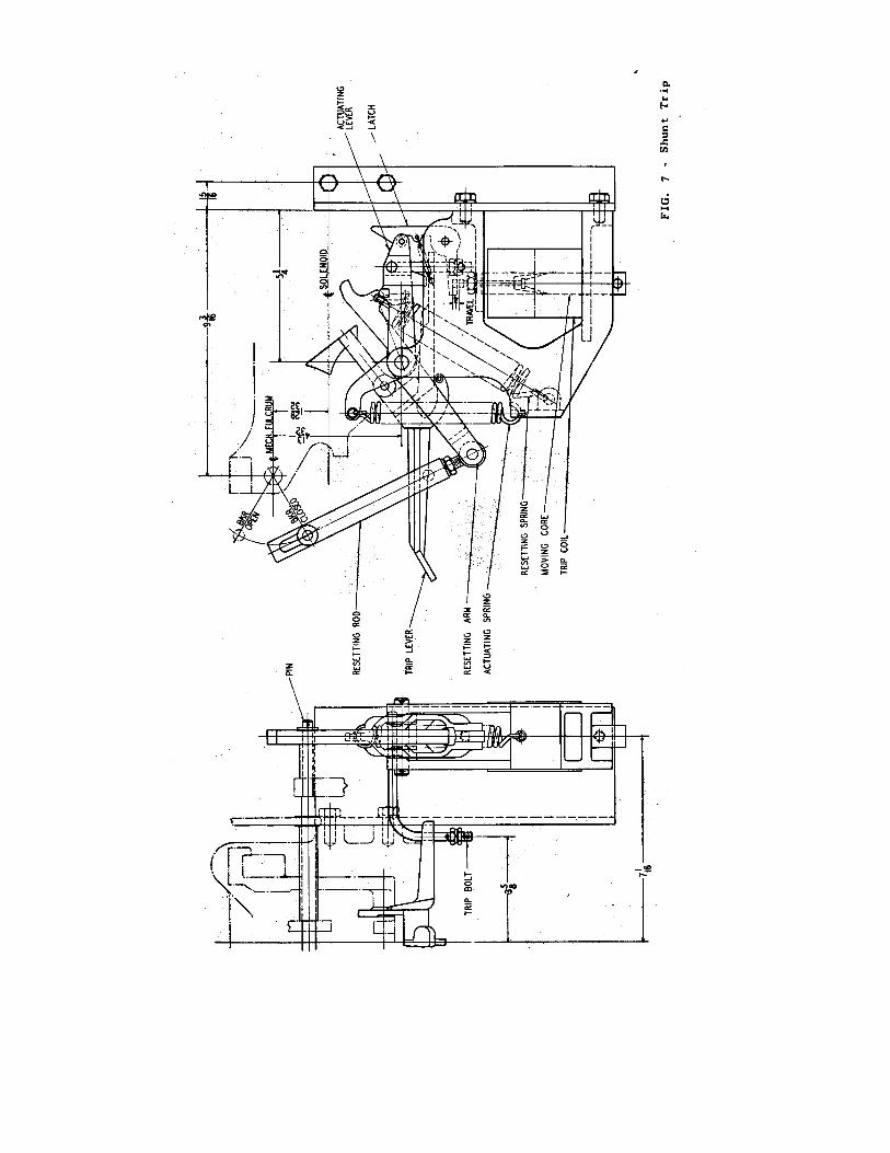
Tripping Attachments SHUNT TRIP
The tripping unit Figure 7, is mounted on
the left hand side of the mechanism. Upon energizing a trip coil a magnetic flux is
9

generated which causes the moving core to operate, through a rod or bolt, upon a trip lever to trip the breaker. The total travel of the moving core is approximately one inch and the mechanism is so adjusted that the core can move approximately 1/4 inch before engaging the trip lever. When moving the core slowly upward by hand there should be at least 1/16 inch permissible travel of the core when the circuit breaker trips
The steady state volt-ampere burden imposed on the voltage transformer is less than 1 volt ampere.
The conventional current transformers are
used for operating the relays but the size is independent of the tripping means and need be only of sufficient capacity to operate the relays. With low-energy relays it is, therefore, possible to trip at very low primary currents. When the relay operates, the capacitor discharges through the breaker low-energy shunt trip coil, tripping the breaker.
Shunt trip coils are designed for
momentary current carrying service and for that reason the shunt trip circuit should be interrupted by auxiliary contacts immediately after breaker is tripped. It is Westinghouse Practice to use for this purpose the first and third contact segments of the ten pole auxiliary switch as counted from the auxiliary switch operating arm end.
The capacitor will hold sufficient charge
to trip the breaker at least six seconds after the charging potential is entirely removed, which is ample time for relays to operate under fault conditions. However, on most fault conditions some potential is available and the device is so designed that 65 per cent of normal potential will give the capacitor sufficient charge to trip the breaker at any time
LOW ENERGY OR CAPACITOR SHUNT TRIP
A low-energy glow lamp connected in
parallel with the capacitor provides visual indication of the charge on the capacitor. When the supply is removed, the condensers will discharge in approximately 60 seconds to 90 volts. The glow lamp in series with the discharge resistance glows at any voltage above 90 volts.
The capacitor shunt trip as applied to these Type DH breakers is a low energy tripping device as shown on Figure 8, Page 17. In it the actual power for tripping is secured by an actuating spring which is latched in the extended position while the breaker is in the open position - the actuating spring having been extended by the action of the resetting spring and lever as the breaker opened. As the breaker closes, the influence of the resetting spring and lever is removed from the actuating spring. On tripping, the disengagement of the tripping latch on this device releases the action of the actuating spring which in turn operates the breaker trip lever. The actuating lever is reset by the resetting spring and through the resetting rod as the breaker opens.
The condenser can be recharged in
approximately 0.3 second by using the special connection shown in Figure 9. This is important, especially when used with fast-reclosing breakers. It should be connected to the line side of the breaker so that it can be charged when the breaker is open.
Renewal Parts
The travel of the moving core is approximately 1/4 inch and there should be 1/16 inch clearance between the latch trigger and the core stem.
When ordering renewal parts, specify the name of the part desired. Also, give Breaker Type, Volts, Amperes and Stock Order Number, (S.O. No.) as found on the breaker nameplate.
The electrical tripping energy is obtained
from a capacitor of suitable size which is charged by a half-wave, dry type rectifier, which in turn draws its energy from the secondary of a step down transformer, 110 to 550 volts, connected to the line side of the breaker. See Figure 9.
10