Embed Size (px)
Citation preview

Authors: Calin Truta
Dumitru Dobrea
Laurentiu Aioanei
Institute for Nuclear Research – Pitesti, Romania

1. Outlines
Technology of welding thermocouples on cladding outer surface: of interest for LOCA and RIA experiments Goals:
ensuring reproducibility minimizing thermo-mechanical effects on cladding fast response during transients ensuring the sheath-thermocouple contact during temperature
transients leading to ballooning and sheath crack
INR Pitesti

Dissimilar joints: Used for instrumented fuel elements, mostly dedicated
to experiments, often between: Zircaloy and stainless-steel, as end plugs Zr in the irradiation section and the SS of the ex-core section
Objectives: Leak-tightness coping with high mechanical stress
Other features: An axial penetration for transducers and cables traverses end
plugs. The stainless steel ex-core end can be further welded with other
stainless steel parts.

Instrumentation layout for a nuclear fuel element

2. Thermocouple Welding Technique 2.1 Ensuring welding reproducibility
Chromel and Alumel wires were used to obtain K-type thermocouples through micro-plasma welding: short discharge, 0.6 A, 0.2 s Ar + 2% H as axial gas, and 100% Ar as radial gas
The ball joints have spherical shape with 0.5-0.6 mm diameters.
The ball joint attached on the sheath through resistive spot welding with controlled load:
1.6 mm flat polished electrode 30-35 Ws pulse, 7.5 ms pulse duration 200 g electrode load (custom-made) Timing and load were adjusted to minimize the thermo-mechanical effects on the sheath
INR Pitesti

Spot welding device (two thermocouples welded on a sheath)

Reproducibility obtained through:
reproducibly clamping the sheath below the electrode in a V-shape copper grounding using two jumpers
controlling the mechanical load of the spot welder electrode

2.2 Testing the welded thermocouples
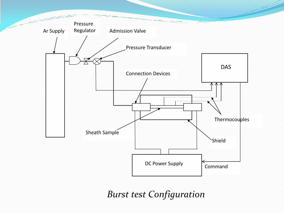
Fuel sheaths with welded thermocouples were subject to burst tests: temperature transients are ended suddenly by sheath cracks
One thermocouple welded at the centre, the other at ¼ of the sheath length
Pressure transducer output & thermocouple signals -> data acquisition system (DAS)
DAS commands the DC power supply (0-700 A, 0-20 V) used to heat the sheath through copper connection devices that are in contact with the sheath sample Commanded temperature: a fast increase to ~300oC, then a plateau
(tents of seconds), then a sudden increase to ~890oC
INR Pitesti
Thermocouples
Sheath Sample
Pressure Transducer
Admission Valve Ar Supply
Command
DAS
DC Power Supply
Pressure Regulator
Shield
Connection Devices
Burst test Configuration

Cladding failure did not occur at the welding location Welding resisted in all tests. Delays between temperature and pressure drops at burst time are small =>
response time is small
INR Pitesti
Temperatures and pressure vs. time
235 oC
307.5 oC
840 oC 876 oC
4.98 MPa
5.19 MPa
17 s
10.5 s

Grain size decrease over ~ 20 m around contact area due to forging process (mechanical load of the spot welder electrode on welded
area)
INR Pitesti
Microstructure of the sheath and thermocouple welding (ball joint on the right)

3. Dissimilar joint techniques 3.1 Devices and procedure
Devices
The furnace for Zy-SS dissimilar joints is an induction heating equipment: water-cooled frequency converter (10kHz, max. 600V single phase) impedance adapter (single-turn secondary coil transformer,
reactive power capacitor compensation) Custom-made heating coil glass vacuum chamber vacuum system (rotary pump and diffusion pump, large range
vacuum gauges) temperature monitors (sheathed thermocouple, electronic
pyrometer, optical pyrometer with filament) control and automation for frequency converter, cooling and
vacuum installation.
INR Pitesti

Piece instrumentation • A Tantalum-sheathed thermocouple is placed in the axial hole of the pieces that were surrounded by the heating coil with a good radial symmetry (part rotation during welding was not used) • Several sample parts are provided with threads to be fixed for subsequent Helium leak test and tensile test.

Basics
The autogenous brazing (without filler) of Zircaloy and stainless steel is based on phase diagrams of the elements composing them. The main systems are [2]: Zr-Fe (~ 76% Zr, eutectic liquid at 936oC), Zr-Cr (~ 28% Cr eutectic liquid at ~ 1300oC) Zr-Ni (~ 24% Ni, eutectic liquid at 961oC)
Thus, the joining procedure should: keep in contact the two pieces at ~950oC where the atomic diffusion
dominates, until critical mixture ratio is achieved raise suddenly the temperature with several tens of degrees, resulting
in formation of a bonding liquid layer between parts cool subsequently the parts to complete the auto-brazing process [1]
(contact surfaces roughness must not exceed 1.6 μm)

Procedure
The vacuum chamber is locked and the vacuum system is turned on When a pressure of 5x10⁻⁶ Torr is reached, temperature is gradually
increased by increasing the excitation voltage of the generator Until 500oC, vacuum quality may slightly decrease due to degassing =>
temperature increase rate has to be controlled to maintain the vacuum level within the 10-6 decade
At 500oC the gettering effect of Zirconium starts, improving the vacuum quality, almost regardless the temperature increase rate
At the above stage parts are gradually heated up to 950oC [1] Final heating is achieved by raising the temperature to 1030 ± 10oC and
maintaining it for ~150 seconds. During this step, observing the apparition of a fine liquid ‘collar’ means that eutectic filler mixture is formed, the joint being almost completed
The plateau at 1030oC ends by steep cooling down to 920oC Slow cooling to avoid solidification cracking of the eutectic zone
Steep heating/cooling profile is required to mark off the 1030 C process, and to obtain reproducible joints [1].

3.2 Joint Examination and Testing
Macrography is useful for:
a general view of the whole joint
fast measurement of the eutectic zone shape and thickness
revealing cracks through details
INR Pitesti
It was performed on cross sections of the joints, either polished, or chemically attacked, to reveal grains Images were obtained with a metallurgy microscope and a camera with remote image acquisition software.
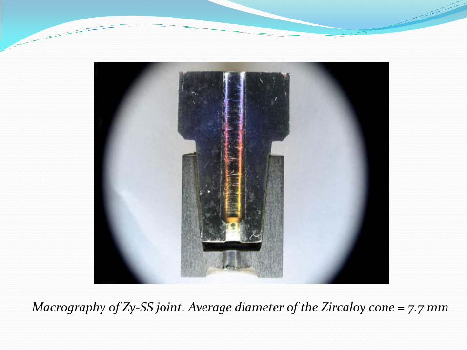
Macrography of Zy-SS joint. Average diameter of the Zircaloy cone = 7.7 mm
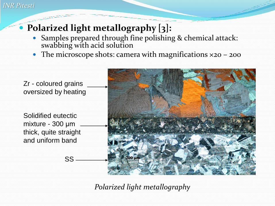
Polarized light metallography [3]: Samples prepared through fine polishing & chemical attack:
swabbing with acid solution The microscope shots: camera with magnifications ×20 – 200
INR Pitesti
Polarized light metallography
Zr - coloured grains
oversized by heating
Solidified eutectic
mixture - 300 μm
thick, quite straight
and uniform band
SS

Electron microscopy: finer polish, but no chemical attack digital imaging and elemental scanning for Zr and Fe conc. Zr islands among dendrites: dendritic solidification involves a
certain degree of segregation towards the SS area [1].
INR Pitesti
Electron microscopy (Zr atoms generate lighter areas, due to higher Z)
SS
Transition
zone
Eutectic
band
Zircalloy Zr islands
Solidification
dendrites

Zy zone: ~95% Zr
INR Pitesti
Elemental concentration profile (Fe and Zr). At bottom, a transverse section in the digital image is presented for comparison
SS zone: ~ 75% Fe + alloying elements in SS 304L (mainly Ni and Cr)
Transition zone ~ 15 μm
Eutectic band, 160-170 μm: ~16% Fe + ~70% Zr + Zr-Ni eutectic

Helium leak test: leakage rates < 6 x 10⁻⁹ std cc/sec: < leakage rate imposed for CANDU fuel manufacture.
Tensile test: global capacity of a fuel element with dissimilar welded plug to withstand the pressure of the fission gasses. Along with He leak test = measure of the homogeneity & strength of the joint.
INR Pitesti
Tensile test (upgraded Instrom machine) diagram
rupture occurs at ~ 23 kN
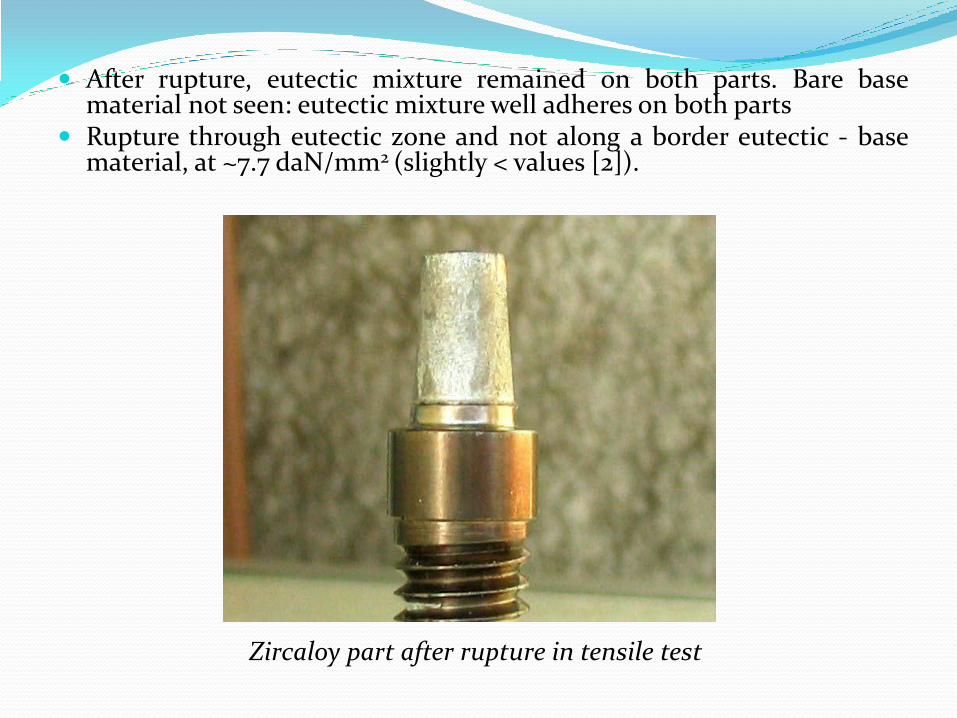
After rupture, eutectic mixture remained on both parts. Bare base material not seen: eutectic mixture well adheres on both parts
Rupture through eutectic zone and not along a border eutectic - base material, at ~7.7 daN/mm2 (slightly < values [2]).
Zircaloy part after rupture in tensile test

3.3. MicroWelds for Instrumentation
Incoloy 800, in form of thin-walled tube is used for nuclear fuel cladding, welded with Inconel 600 end plugs
For instrumented elements, end plugs need to be bored and prolonged with a stainless steel capillary tube as a duct for pressure measurements, or as passage for brazing a sheathed thermocouple
The weld has to be leak-tight below 10-7 std cc/sec, even after repeated exposure to high temperature and internal pressure
Such joints were welded both with microTIG (tungsten inert gas) and microPAW (plasma arc welding). A long taper is needed to avoid stress concentration points.
Welding parameters have to be adjusted such that the weld would be:
large enough to have a good dilution of the base materials (no filler used)
small enough not to melt inside the tube opening. One may see in fig. 10 [1] such a microplasma weld.
INR Pitesti
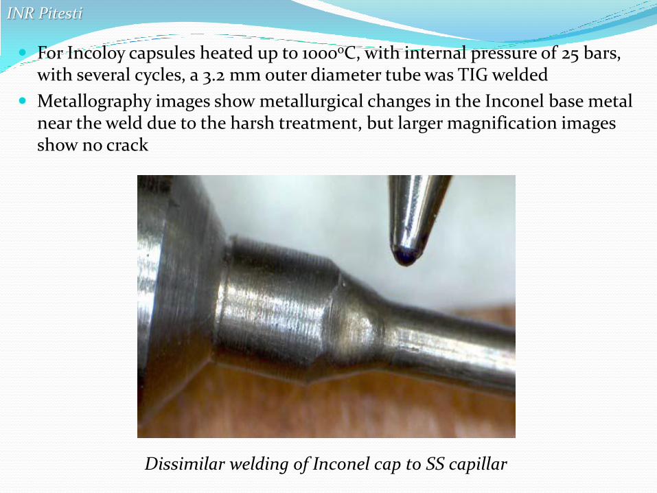
For Incoloy capsules heated up to 10000C, with internal pressure of 25 bars, with several cycles, a 3.2 mm outer diameter tube was TIG welded
Metallography images show metallurgical changes in the Inconel base metal near the weld due to the harsh treatment, but larger magnification images show no crack
INR Pitesti
Dissimilar welding of Inconel cap to SS capillar

4. Conclusion
The micro-plasma technique for obtaining the thermocouple junction proved accurate and reproducible leading to ball diameters about twice the diameter of the wires.
The resistive spot welding ensured reproducible timing and load. It also ensured minimizing thermo-mechanical effects of the spot welding on the sheath, as proved by metallographic examination after burst tests: the area affected by welding was small (around 20 m).
The vacuum induction device, the manufacture of parts and the working procedure itself are all fully suitable for obtaining joints through eutectic brazing between Zircaloy and Stainless Steel.
INR Pitesti

Conclusion (contd.)
The joints are leak-tight and have enough strength.
The dissimilar welding process proved reproducible.
The techniques presented in this paper work in conjunction for increasing the capability of the Institute in nuclear instrumentation field, for own projects or for potential partners.

Acknowledgements
We thank our colleagues, Ing. Constantin Pitigoi for burst test device setup and operation, Dr. Maria Mihalache and tech. Mihaela Ilie for performing electron microscopy and metallography.
INR Pitesti

References
[1] C. Truta and colab – “Dissimilar Joints for Nuclear Equipment & Instrumentation” – Int. Conf on “Innovative Technologies for Joining Advanced Materials”, Timisoara 2012.
[2] Francois Jacques – “Jonctions diffusees Zircaloy2 – acier inoxydable” – Report CEA 2643, Saclay, 1964
[3] P.E. Danielson and R.C. Sutherlin “Metallography and Microstructures of Zirconium, Hafnium, and Their Alloys, Metallography and Microstructures” - Vol 9, ASM Handbook, 2004, p. 942–958
INR Pitesti


![Quality Catalogue: Competency and Quality Framework for ...prisonstaff-project.eu/output/O2.pdf · Adrian SĂMĂRESCU (University of Pitesti [Universitatea din Pitesti] - Romania)](https://img.dokumen.tips/doc/110x75/5e2282c167b9306a2106e3d4/quality-catalogue-competency-and-quality-framework-for-prisonstaff-adrian-smrescu.jpg)


