Embed Size (px)
Citation preview

VOL. XVIII, No. 10 BULLETIN 1922-23 OF THE
OHIO STATE UNIVERSITY AGRICULTURAL COLLEGE EXTEN;lION SERVICE H. c. RAMSOWER, Director
Installing Farm Drainage Systems By
Wendell P. Miller
Extension Specialist in Agricultural Engineering The Ohio State University
Contents Staking the tile lines. . . . . . . . . . . . 3 Grading the ditch.. . . . . . . . . . . . . . . 4 Digging the trench. . . . . . . . . .. . . . 6 Buying good tile. . . . . . . . . . . . . . . . 10 Laying the tile. . . . . . . . . . . . . . . . . . 12 Tile connections. . . . . . . . . . . . . . . . . 15 Inspection and connection basins . . 17 Protection of outlets. . . . . . . . . . . . . 20 Surface inlets. . . . . . . . . . . .. . . . . . . 23 Final inspection. . . . . . . . . . . . . . . . . 23 Blinding the tile. . . .. .. .. . . . . . . . 24 Filling the trench. . . . . . . . . . . . . . . 24 Field work.. . .. . . . . . . . . .. . . . . . . . 25 Tree roots. . . . . . . . . . . . . . . . . . . . . . 25 Monument . . . . . . . . . . . . . . . . . . . . . . 26 Make the final map. . . . . . . . . . . . . . 26
THE OHIO STATE UNIVERSITY, COLUMBUS, OHIO, AND THE UNITED STATES DEPARTMENT OF AGRICULTURE, COOPERATING
FREE-Cooperative Agricultural Extension Work-Acts of May 8 and June 30, 1914.


Installing Farm Drainage Systems A tile drainage system is crop insurance. There are, however,
no insurance companies thru which to insure the life of the drainage syste.m against destruction by the plow, collection of silt, washouts, tree roots, muskrats, rabbits, broken tile, and clogged outlets.
The insurance of long life and successful operation must be built into the drainage system during the days of its planning and construction. All parts of a properly constructed drainage system should last no less than a hundred years. Why then was 15 percent of the total tile laid from 1900 to 1920 replacement construction? The tile-drainage census made by the United State Bureau ,of Census in Ohio in 1920 showed that nearly 90 percent of this replacement work was made necessary by failures caused from improper construction.
No line of tile is too short, no system too small, to escape the damage of one broken tile, or of one clogged outlet. Every small system may some day become a part of, or the basis for a larger system. The small drainage system, therefore, merits careful attention to those details that make it possible for a small stream of city sewage to thread its way underground, sometimes for miles, without meeting ,obstruction.
Thoro, uniform tile drainage of Ohio soils costs from $30 to $75 per acre. This large investment is buried under the ground. We cannot see it, and perhaps this is why we incline little to consider unseen forces constantly at work to destroy this investment.
This bulletin presupposes that a carefully made plan for the drainage of a tract of ground has been prepared. The plan should give the layout of the tile lines, their direction of flow, spacing and size, together with a statement of the average depth of drainage best suited to the particular soil in question. The fallowing pages deal only with the details of constructing the permanent tile drainage system. The operations in installing the drainage system are discussed in about the order in which they are performed in the field.
Staking the Tile Lines Whether the complete system is to be installed at the start or
only those lines which tap the wettest parts of the field, the plan should show the final, complete layout. Working from the complete
3

plan makes possible the location of the first work, so that later additions may be installed in their proper place without causing uneven or double drainage and reconstruction of mains. Stake out the lines with guard or finder stakes before commencing the digging. Where accurate levels are necessary, before digging, a hub (Fig. 1) should be set beside the guard stake at every 100-foot station. A hub is a stake from 8 to 12 inches long driven flush with the surface of the ground, upon which the level rod is held while taking elevation readings. The hub is used as the point from which the depth of cut is measured and from which the grade bar is ·adjusted. See Fig. 1. In digging a trench by hand always use a string, to insure a straight ditch.
Grading the Ditch The old-time, practical ditcher used water to grade by when
there was water in the trench, and his eye when there was no water. With a line several hundred feet long, it is almost beyond human power so to judge the grade by the speed of the water that a uniform slope of 1 or 2 inches can be given to the bottom of the ditch. Because of this he often ran the tile line to the surface of the ground to keep the water running. His eye was even worse than the water and sometimes he pinned his faith on the tile as a syphon to draw the water and silt out of the low spots. With slopes of more than 4 inches per 100 feet, it may be safe to rely on water, but the eye should never be relied upon for grading until the slopes are more than 1 foot per 100 feet.
The safe way is to run the levels on both the mains and laterals with a drainage level. The sample page of field "Level Notes" in Fig. 1 shows how the levels are figured. The last column of figures, giving the distance from the hub to grade, or the depth of the ditch, is the one used by the ditcher in setting the grade bars. To use these figures for setting grade bars, it is necessary to have a rod of suitable length graduated in feet and tenths. A convenient length of rod for most farm ditching is 5 feet. If the ditch is more than 5 feet deep at any point, the rod should be longer. Changing the length of the rod will not change the following method of setting the grade bar.
For example, at station 3 plus 50 the depth is 2.58 feet. Place the finger at 2.58 on the rod. The portion of the rod below the finger represents that part of it which will be below the ground when in the completed ditch. That portion of the rod above the finger represents that part of it which will be above the ground when held in the completed ditch. Holding the finger on 2.58 the rod is inverted over the hub. The position of the finger will desig-
4

01
moH P1Pt OIL ttN1HC. 0 0LL
1
~ Fl GQADUA'fED QOD ADO VH'..O A~ GAG~ 51'1CK.
r11i lj'
HA\L \\f..'l!...{ OP_ C.lAMP
i?'"'.711\IF:?:' ··~'4'.:i ~ \.llTH g"l 1AQG[1 All.~
t 'HlHCt----- --?oLr
\.llH<; HUT
PLAN Of IAll.C LT A\?..M fA)TEHlliG
TWO TIPD Of BA R.:-i G l2AD L
so o' ---------·-·····-------__.,..__
CUAD.D OIL flttDt:U. liAK.t:'..
-~
Jlo
IJH 0
I 2.
21-50 J
3-t-SO 4-5
50 a·
-- ---- - --l -,/llHl OP _~1C..H1/
.,. )TA. 3-i-jO
+
715
level Nofe5
HZ
107 75
... --· ---.....------------
-
825 815 145 7 25 6B3 7 IO 645 '70
flub
10000 9750 91&0 /0030 /0050 /0072 /0065 /0130 /Pl J5
Grade Huh lo Elev bollorn
'1702 248 '17 32 2 28 1762 2G8 97 77 2 73 ?l '12 JOO
1807 258 '/822 308 9952. 2 83
-
1--1~
!Wb la Crdbol'
252 2 72. 232 2 27 200 242. 1?2. 217
1111 jTA.4
I Q~-~~~Hf _ti_ :_9 ;}9_!:(I"_1.-;:_~~oV ~~~~ii--~
Fig. 1.-The careful use of grade bars assures accurate grades in hand-dug trenches.

nate the height of the grade bar. In other words, the grade bar may be located accurately by inverting the rod over the hub and reading down from the top the required depth of cut, regardless of the length of the rod. The rod is also used as the gage stick over which to sight in testing the grade between stations. This use is shown in Fig. 1.
The grade bars and gage stick can also be used to secure a uniform slope of the ditch bottom without having the line surveyed. A carpenter's level on a box or a post is used to determine whether or not the land actually has a fall in the desired direction. After proving that there is enough fall, find the required depth at the outlet.
Grade bars like those shown in Fig. 1 are set up at the outlet and at the upper end of the line or at points of changing slope. Intermediate grade bars are then sighted in at 50-foot intervals. By means of the inverted 5-foot rod the depths at the intermediate stations can then be read direct. If the depths are satisfactory, the digging may proceed, but, if the depth at some intermediate station is too shallow or too deep, it means that the grade bar at the upper end must be raised or lowered. After the grade bars are all adjusted the fact that they give a fall to the ditch can again be checked by means o.f the carpenters' level by leveling it on top of the last grade bar and sighting down the line of bars. If the tops of the bars fall below the line of sight, the ditch will have a fall toward the outlet, and the bottom of the finished trench wi11 be parallel to, and 5 feet below the line of sight over the grade bars.
The grade bars, or targets, set by the ditching-machine operator are leveled in exactly the same manner as those for hand ditching. The only difference will be that the length of the gage stick will be 8 or 9 feet, instead of 5 feet.
The carrying capacity of a tile drain depends upon the velocity of the water. The velocity and hence the efficiency depends upon the rate of fall and the evenness of the grade. The rate of fall in a tile main should not be decreased without increasing the size of tile enough to give the same capacity. Unevenness in the grade wi11 often check the velocity of the water enough to cause the dropping of sediment. The collection of sediment once started at low spots, will usually continue till the tile is completely clogged. Correct grading is, therefore, of first importance in insuring long life for the tile drain.
Digging the Trench The trenches for tile drainage may be dug by hand, by horse
drawn ditching plows and machines, and by power ditching ma-,. "

chines. The two most satisfactory ways are by hand tools and power machines of the revolving, cutting-wheel type driven by a gasoline eng:ne. The digging should start with the mains, commencing at the outlets. The lateral trenching should follow in order, beginning each line at its point of connection to the main.
I
Fig. 2.-Tools that form a part of every up-to-date ditching and tile-laying outfit.
Hand Digging The hand tools shown in Fig. 2 are the straight ditching spade,
the skeleton spade, the round-pointed shovel, the tile scoop, the tile hook, the ax, the mattock, and the grade bar. Ditching worth doing at all is worth doing well. It is real economy to get a good set of tools, a set that meets the conditions of the job. The ditching spades are made in 14-, 16-, 18-, and 20-inch sizes. The 18-
7

inch size is best for most conditions. If the farm can afford only one spade, let that be an 18-inch, straight ditching spade. The skeleton spade is a real labor-saving tool when the ground is wet or waxy and hard to throw off the blade. The round-pointed spade is not to be recommended, because the inner edge of the blade cannot be kept exposed on each cut.
The real knack of using the ditching spade is not easily attained. The secret of easy spading without leaving most of the dirt in the trench is to place the spade for each cut so that the inner edge of the blade will always be exposed as shown in Fig. 4. In Fig. 3 notice that the cut is started with considerable slope, while the bottom 3 or 4 inches of the cut is made vertically. This places the fulcrum near the weight end of the lever represented by the spade. The spade handle is the power end of the lever. Placing the ful- ~ crum near the weight end de- ·'
::;...._ "--"' creases the effort required to break the slice loose from the bottom of the trench.
Before starting the trench the depths which will be required should be studied. If the trench can be cut with two spadings the top width need be only 12 inches for tile up to 8 inches in size,
8
:. I ·-~ ·-,..,..::____· ·.:::::--:: ·-
.. ~~.: .~ .~·

and with wider tops for larger sizes of tile. If three spadings are required the top width should be 16 inches for the small sizes of tile. The last spading need be only wide enough to allow easy bedding of the tile, varying from 6 inches for 4-inch tile, up to 16 inches for 12-inch tile. Do not waste energy in lifting dirt out of a ditch that is wider than is needed to lay the tile.
A good handler of the spade leaves few crumbs in the bottom of the ditch. These few are removed from the top lifts of the trench by the round-point shovel. No short- or long-handled, square-pointed shovel will do this work as easily.
The crumbs remaining after the bottom lift is spaded out should be removed with the adjustable tile scoop. The use of scoop smooths the boUom of the ditch and cuts a bed or groove in which
PADt:. VliH 0.Hl'.tDCO t. f lU. t.
Fig. 4.-Correct placing of the spade with one edge exposed will save time and effort.
to lay the tile. The scoop can either be pulled or pushed along the bottom of the trench. The most satisfactory work is done when the operator stands on the first lift above the bottom and pulls the scoop. The gage stick is used along with the tile scoop to test the finishing of the trench to the desired grade.
Horse Drawn Machines Trenching by horse-drawn machines requires skill in driving
the horses and in operating the machine. It is difficult to use the grade targets that are used with the power machines, hence, the bottom grade cannot be finished true without hand work. Several of the horse-drawn ditchers will remove the top 20 to 24 inches of earth cheaper than it can be done by hand, if the ground is not too stony or hard.
Power Machines Under most conditions the power ditching machines of the
revolving, cutting-wheel type, with caterpillar treads, propelled by a gasoline engine do the most economical and satisfactory job of trenching. As with any other engine, a carefully trained operator is required to make the final trench correct in line and to grade. To guide the operator in keeping the ditch bottom on the proper level the grade targets explained under grading the ditch are
9

kept set at the proper height for a distance of 200 or 300 feet ahead of the machine. The cutting-wheel frame is supported by a long sroe which smooths the bottom of the trench. The bottom of the shoe is soled with an iron bar which leaves a distinct groove. By laying the tile in this groove, they are brought into perfect alignment. To prevent dirt from rolling back into the trench before the tile are laid, a shield can be attached to the digging-wheel frame. By laying the tile in the portion of the trench protected by the shield, as shown in Fig. 5, no hand cleaning will be required.
Fig. 5.-String the tile 6 feet to the rig-ht of the ditch line. Use a shield on the machine to keep the ditch bottom free from crumbs. These factors plus a tile hook make it possible for one man to keep up with a machine digging
150 rods pL~ day.
Buy Good Tile Drain tile are made of th:ree materials. These materials are
clay, shale, and concrete. Clay and shale are dried, ground fine, mixed with water, pressed thru dies, dried again, and then burned in kilns at temperatures just below the po:nt at which the materials will fuse. Depending upon the materials used, the tile may be
10

burned to a red color, they may be salt glazed, or they may be vitrified. The idea that a good drain tile is one which is porous enough to permit water to pass thru the wall of the tile is erroneous. Exact measurements of the amounts of water that will pass thru the shell of a very soft 4-inch, clay tile show that only one-twentyfifth of a gallon of water will pass thru the shell in 24 hours. It would take over 2,000,000 feet of these tile to abso:·b enough water thru the tile wall to make the 4-inch tile run full at the outlet if the fall were 5 inches per 100 feet.
The specifications by which drain tile are tested provide two tests; one of absorption, and the other of crushing strength. Three standard grades of drain tile are established by the specifications. The grades are known as Farm Drain Tile, Standard Drain Tile, and Extra Quality Drain Tile.
The specifications provide that Farm Drain Tile shall not ahsorb mo:·e than 11 percent of water by weight under the standard boiling test; Standard Drain Tile, not more than 9 percent; and Extra Quality Drain Tile, not more than 7 percent. The minimum average supporting strength of Farm Drain Tile shall be 800 pounds per linear foot for all sizes up to 12 inches; of Standard D;:-ain Tile, 1200 pounds; and of Extra Quality Drain Tile, 1600 pounds. The same tests apply to concrete tile.
There is no difference in the efficiency of tiles made from the three different materials, provided the tile are the equal in strength and in the physical characteristics such as smoothness, true shape, full diameter and length, square-cut ends, and freedom from cracks. It is never true economy to buy second-grade tile or even firstgrade tile that will not come up to the above requirements of strength for Farm Drain Tile. If this suggestion were followed, immense quantities of seconds and soft or over burned tile would go on the scrap heap instead of being installed by Ohio farmers in the name of economy. At the same time there would be a large decrease in tile drainage failu:res.
Note carefully when buying tile that they are full length, full diameter, perfectly round, have square-cut ends, are without jagged or notched edges, and are free from cracks. In good, concrete tile the sand and stone particles should break, rather than pull out of the cement when a piece is b:::-oken. The tile should overrun in length more than enough to make up for breakage in shipping and field handling. A very good field test of quality is to tap the tile with a hammer. The good tile will give off a clear bell-like tone. The higher the pitch the stronger the tile. The weak, cracked, or overburned tile will give a dull, dead tone.
11

Laying the Tile Laying of the tile should commence at the outlet end unless
the ditch is dry. In a dry ditch begin at the most convenient point, provided the route of the ditch has been surveyed or you are sure about the fall. The easiest way to lay the smaller sizes of tile is with the tile hook shown in Fig. 2. The tile layer stands on the ditch bank, and picking up a tile on the hook swings it into place in the bottom of the trench. If the tile does not line up with its neighbor, it may be rotated with the tile hook to make it lie straight as shown at the left in Fig. 6. Do not try to make a tight-fitting
. T -1· I . ! . ; 11 ·· · . . . · / ....
, . ·/ : • ~ : .; • j .' . . . .I~ A;y
·11· 11=.
Fig. 6.-Tile without square ends can be rotated to make them lie straight in the trench with the wider opening in the joint at the bottom. Cover wide
cracks with bats.
joint. Leave from l/s to 1,4 inch of space between joints of tile, depending upon the hardness of the tile and the character of the soil. Soft tile will expand enough to entirely seal a close joint. In some cases the expansion may even crush the tile.
At a field demonstration held in 1921 one farmer said that his tile would not draw any water .. The group was asked to stop at his farm. The tile were uncovered on three lateral lines. Before any tiles were removed for inspection water was poured into each hole. The height of the water in the hole was measured. After the drainage outlets and layout had been described and inspected, the water in the holes was again measured and found to be at practically the same height. Tiles were then removed from the lines and the water ran away at once. At two of the three inspection holes the tile were so tight that they could not be pried or rolled out of the line and had to be crushed. Upon inquiry the farmer explained that he had taken pains to get close-fitting joints, because he thought the soil would run into the tile thru the cracks. Here was an example of a large investment in tile and labor proving almost valueless because of not leaving a crack between the joints, thru which the water could enter.
If experience shows that the tile do get some silt from a particular soil, or in the case of quicksand, the tile joints should be
12

covered with sod, straw, or short pieces of roofing paper. A cover of this sort will keep the sand Ol'._ silt from filtering thru the joints until the soil around the tile has become sufficiently solidified to prevent further difficulty.
If the ends of the tile are not cut square revolve the tile until the wider part of the crack comes at the bottom or cover the crack
= ~ COUNTY DlTCH 7 ~ l v-·-•-:;;7'M;;;;•-o·~~·c;:•1001-=~-=-·- i~O~£BK'.,'--,~~E;!_, __ ro-·-a;;-·-~·-CJSr
i i ~ t c)0 :z..J \Ji ·~e'.') i I: ~ j ~ '- f I - < I Or<"<,,-~ " )JV . i l .~ I ,, "-.5- L,i__'(( 11 ,--' I i'' ! I t ci noOO\.IAHa<110><H<LH[ r\() ;C»D_~ >!,,_} Q [
: I ~ " ! L .. _v (7)) '---l'.:)'< '-.'! ! I f § ;: j ----;;, ~ '\ 0 I l i ~ ,~ l l};I) ro . ) r 1\ ~·,., ) ,~ VJOOD.S i i1 J 10 ,y ~-! I :: r\ tO __,.__/ 0) \._jji~ j il G /ill t \ (1) \_.!) j I l I §U/ • \'':: 0 i f f \. J 1 \"'-l.'.:l ~ I 1 I i \'-C l...~ GJ T
t·t r i\\ ({]) I 101 1 \~ I t~ ! ~06)i -1 l E. \ COHCRf:>r: ou;:,,i-1 I ·IQ i CONN!:C'TION BA51" ~
· 4" LATf:R.AL!J .50 rttT APART ; / 10" MAIN ~ t~I ALL LATf:'!l.AL> TO ec- LAID A• Nf:'AR. :;o· ni;eop A> coHTOU"- or-- GRout1n ;?cR.Ml'f> 4-f ~ I~!
i l ~.-; 8 ' I i 1 i 4~ ~ 1" '"· n I i J. l 1' ~" - I li:,f I I I <) n '"" ·1 i ;.,-'- (!iy' Q. . }, F 6' HAI\'\ c:: 1 .ir.., o 1
f T-·0·-f·-·: "o (}Ji WO o gs Q !
t0 o "' I 1 j) _GJQ Gn l t cDH_l1 D I CJ(j i)l}I 1 T i w. - r1~i'~.:...t-;1~-1-· 0 '\efJ) 0 l l 1 .~~~~J J G G G (!;/ 8:i. 0 o t I ir - - <:t<OVC- o o r.o ~ -l t~~·~_._L_._,_.~·-·-·-·-·-·-·-·-·-·_?J.&.o_. ~Q l ~8:~:.~;. -~~-~-~l
Fig. 7.-The final map of a farm drainage system should show the exact size and location of all tile lines, important junctions, inlets, inspection wells, and outlets. Letters indicate location of important details shown in the other
illustrations.
with a bat as shown at the right in Fig. 6. In quicksand it. is sometimes necessary to lay the tile with the wider opening on top, in which case the top of the tile should be covered with sod, straw, or
13

roofing strips. It may also be necessary in quicksand to lay boards in the bottom of the trench, to support the tile and to keep them in proper alignment. Rough inch boards, from 4 to 6 inches wide, will provide sufficient support for tile up to 10 inches in size.
If the ends of the tile are so uneven that it is impossible to avoid leaving a wide, open joint, broken pieces of tile called bats should be laid over the hole. If no broken tile are available for
Fig. 8.-A sewer "Y" and a 6"x 4" sewer reducer make a perfect junction of a 4" and a
5" Hne to a 6" main.
patch'ng holes then make bats from some of the tile that are causing the difficulty. Do not cover the tile with any coarse materials like cornstalks or brush that will leave spaces thru which the water may travel outside the tile. Water running outside the tile may undermine them and allow them to roll out of position, thereby stopping the drain.
The tile layer should be the final inspector of every piece of tile as it goes into the ditch. He should keep ever in mind that it is the weakest link which causes the chain to break. One defective
14

tile or Joint may ruin the whole length of lateral above it or cause all the mains below it to be filled with mud from a washout. Read the notes on filling the trench in connection with the above suggestions on laying the tile.
Connections In connecting tile of two sizes in a straight line the resulting
crack may be closed tight with a bat. This method was used at I on the installat10n shown in Fig. 7. The connection is shown in detail in Fig. 10-Junction at I. Smaller tile may be telescoped within large tile and the joint covered with a bat or with concrete. The perfect way of joining tile of two sizes is by a reducer hke that shown in Fig. 8.
The connection of two lines of tile such as a lateral to a main or of a submain to a main should be made water tight. The water may come into the larger tile under such pressure that it will cause eddies which will escape thru the least crack and start cutting away the earth outside the connection. This cutting usually goes on until the connection falls apart and the earth caves in and fills up the drain.
The surest way to prevent the drainage system from being ruined by washed out junctions is to use sewer pipe fittings in the manner shown in Figs. 8 and 9. These fittings are worth all they cost by insuring the permanency of the system and by saving time in making the connection. Equal results may be secured from the use of drain tile Y's, provided concrete is substituted for the collars of the sewer pipe at the joints above and below the junction on both lines. Next to the best method is the use of drain tile Y's without concrete.
If neither sewer pipe nor drain tile fittings can be secured a fairly satisfactory junction can be made by chipping a hole in the side of the main as near the top as possible. The hole should be the same size as the incoming tile. The lateral tile is chipped or chewed off with a monkey wrench to fit the curvature of the la:·ger tile. The chipping of the hole in the larger tile is done with a lightweight hammer. Choose a soft tile, begin at the center of the desired opening and peck away lightly until a small hole is worked thru the shell of the tile. The hole is then enlarged with heavier strokes until the jaws of a small monkey wrench will slip into the hole. The wrench is set with jaw opening slightly wider than the thickness of the tile shell. The hole may be chewed out with the wrench and with less danger of cracking the tile than by the use of a hammer. This type of connection should always be cemented
15

to prevent the escape of water which will form a whirlpool around the outside of the junction.
In every case where two tile lines join at or near the same grade, the incoming line should empty its water without checking the flow in the other line. The water should enter in such a way that the velocity of the incoming stream will not be lost. This means that the last few feet of the incoming line should be gradu-
Fig. 9.-A double sewer "Y" used to make a perfect connection of a lateral to a main. The machine cut straight across the main and the
curves were dug out by hand.
ally curved in the direction of flow of the line to be entered. The fittings used or made should be Y's, rather than T's. The latter will make the incoming stream cut across the current in the main tile checking its velocity. In the layout shown in Fig. 7, the junctions at J are either given a curve down stream before entering the main or the laterals meet the main at such an angle that no curve is necessary. At G on the plan it will be noted that the laterals cross over the main and enter at right angles to the direc-
16

tion of flow. At these points the top of the main was below the grade line of the laterals. As the digging was being done with a power ditching machine, it was more convenient to dig straight across over the top of the main. The vertical junction was made by joining together two T fittings; one in the main, and the other in the lateral directly above it as shown in Fig. 10. By this method one junction serves for two laterals. The dead end of laterals or mains should be permanently closed by some means similar to that shown in Fig. 10.
Where the ditches are all to be dug by hand, and the location of the junctions of laterals with the main are known definitely before
~mArr C ll.Ol l l tCTlO!i AT JUHC.11011
J llHCT!OH AT J
HtAD or l1ML
Fig. 10.-Careful construction of junctions give the tile drainage system long life. All connections made with drain tile should be cemented. Laterals
should enter near the top of the main.
the tile of the main are laid, the appropriate fitting should be installed in the main line as the tile are laid. The open inlets of the fitting should be blocked with stone or boards to keep out dirt until the laterals are connected. If the digging is to be done with a machine it is not a good plan to install the fitting as the main tile is laid. The curve will have to be dug by hand, and the exact location for the junction is not easy to determine in advance.
Inspection and Connection Basins In large, complicated drainage installations, it is quite often
necessary to provide for the connection of three or more mains at one point. The different directions from which they come together, or differences in their elevation may make a connection basin necessary. A connection basin like that pictured in Fig. 11 is located at E on the layout shown in Fig. 7. Because the connection basin is located in land that will be plowed the basin is capped below plow
17

depth. It can be located by the large size and greenness of the crops grown over the basin as a result of the extra drainage.
At E' on the same farm a similar basin made from 24-inch tile is used to catch any silt that may come down the tile from the surface water inlets in the barn lot and at the culvert near the house. This inspection basin is located on a fence line out of danger fzom wagons, tractors, and plows. It comes to the surface, and is capped with a heavy, concrete slab that cannot be broken or moved off by
j tCi101'!
1!' tOCA'TC:P 1H PLOWC:ll AO.EA BA~lH MAY Bt. CA?'Pt.D l?>ttO'W PtOYJ Dt:P'TH
PLAN Fig. 11.-Silt wells permit observation of the flow and detection of breaks. They are used at junctions of mains to collect dirt that may come from surface inlets or washouts. Use sewer prpe or concrete when used as surface inlets
in ponds or gullies.
livestock. The 24-inch tile provides plenty of space to catch the sediment that will settle out of the water, and is big enough to be easily cleaned.
Inspection basins afford a ready means of checking up on the work of the smaller units of a large system. If one of the mains should be carrying muddy water and all the others clear water, it is time to begin searching for a br:oken tile, a washed out connection,
18

If THE. TILE. MAIH H>LLO\.I~ A HllHAC.t. WAiE.D..-COU!l.H. 11" ~l-lC>l•LD ~t. Dtl'l!CTf.D DO\.JN Yfll.EA'M liEAll.. 1HE. Oll1LE'T TO Pll.E.\IE.HT 11 r ll.Ol'\ IYE!Nc; \/Arn tD C1llT
Fig. 12.-Tile outlets should be protected from undercutting, weeds, frost, rabbits, and crushing by incasing the last 10 to 20 feet in concrete. No forms
are required to build this outlet.
19
or other failure. It may be that a horse has broken thru into a cavern washed out by the whirlpool outside a poor junction, and surface water is now carrying mud into the main.
Protect all lines that come thru quicksand deposits by silt and inspection basins; also, all lines that for any other reason may be expected to carry anything but clear water.
Connection and inspection basins should be installed immediately after the work has passed the point of their location, as it will be difficult to dig the well after water has started to run thru the lines. The basins can best be made of common drain tile, sewer pipe, or a combination of the two. Connection basins may also be made of concrete, using sugar barrels for the inside form, or they can be made with square box forms, with size and depth to suit the location.
Protection of Outlets The subject of outlets for tile drainage systems deserves to
head the list of important details, for without some definite place
!OP er c. UOUND
J I I I I I I I I I
I I I I \10' ~ ,
it tr.
j UD.f'AO'.. \.JATttl... CHAHHtl
Fig. 13.-Where the tile main follows a flood water ditch, it should be dug at one side of the channel to prevent washouts. Keep the shallow open ditch
sodded to prevent erosion.
for the water to escape freely at all times no amount of lateral drainage will be worth a dollar.
The ultimate outlet of all farm drainage is into some river, but the immediate outlet for a large portion of the farm underdrainage of Ohio is into some public drainage ditch either' tiled or open. Thousands of acres of Ohio farms are now without adequate drainage outlets, either because of the failure of the designing engineer to realize the real drainage needs, or because of the opposition of property owners thru whose farms the water must flow.
In driving along a 10-mile stretch of public highway in Putnam County no less than 40 submerged outlets can be seen. The lateral
20
systems dependent upon these outlets in many cases may literally be called dead drainage or a lost investment.
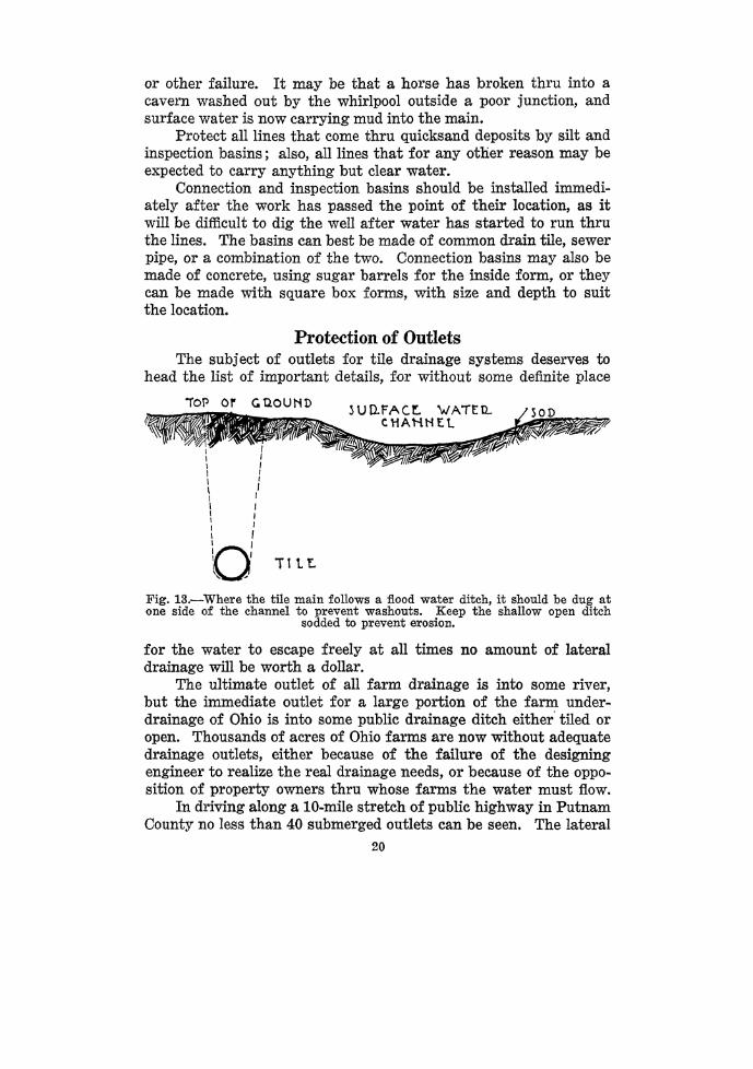
No drainage system should be started till the location and capacity of the outlet to be used is definitely determined. Levels should be taken to determine if the outlet will be low enough at all times to afford a free opening for the most distant swale which it is desired to reach with the system. The protection of the outlet to a drainage system should receive the finest workmanship of the whole job; yet there are thousands of tile outlets along the road ditches of the northwestern Ohio counties, that cannot be seen until the
511 TO 2.4"
Tl L f..
TOP V 1 E 'vJ
.,.....,._,.....----.-..... roll. ~UU.fACt. \tJATE:.~ . . . •
-,\,;.\\~J~(>;:: __ ... :~·et: :_ .. ~ :<:::;)i1~1r~J11-J1I \ \1 \ ~- . . ' . . . . . f- I ~ ':"- I I I U-: \\ 1 "·. : . -. . . . ' .. ·. : . :;· . l i I II
\ : 1 \Uk '.,, ', , _ • . , • • : • • •' ' , , ~·: I
I
I l A?tl.01'1 AKD rl?'.-6,DWALLI i l : POUlltD S'E?AllA1ft'( I I I I I I 1---------L---------- _____ J._ .... ______ J
fQO'H'T Vlt\.J Fig. 14.-Where the tile and flood water channel must outlet together build a substantial head wall. Provide surplus capacity at the spillway for flood water.
weeds and dirt are removed with a shovel. Other thousands are providing fine hiding places for rabbits, muskrats, and skunks. Still others can readily be found by the deep gullies they have washed back into the :fields, in some cases causing the loss of a ten-foot strip of land along the roadside fence.
21

In the bulletin on "Drainage Layouts" by Virgil Overholt, is described a cheap way to eliminate the unprotected roadside outlet. The plans for the two types of outlet protection which will meet all Ohio conditions are shown in Figs. 12 and 14. An outlet of the type shown in Fig. 12 is located at B, Fig. 7. Note that this outlet ditch is dug at one side of the broad, open relief ditch (see Fig. 13), which is left to carry the flood water. The tile ditch is curved down stream just before it enters the open ditch, so there will be no danger of flood water coming down the open ditch and washing the covering off of the tile near the outlet. This type of outlet takes a minimum amount of concrete and requires the building of no forms other than boards staked at the end of the tile. These boards can also be made to hold the grating bars in place. The sides of the trench serve as a form to hold the concrete. The bottom 4
Fig. 15.-Tile lines do double duty in preventing erosion when stone-filter inlets are placed in flood water channels. The stone screen out dirt and debris which
would clog the tile.
inches is poured first. Be sure to put in the bottom reenforcing rods. After the bottom has set slightly, the tile are laid in place, and the concrete poured for the top and sides. The trench can be filled the next day. The only substitute for the concrete in this type of outlet is a piece of old well casing, gas pipe, or length of road culvert pipe.
For locations where it is necessary to have the surface water and the tile outlet at the same place, the head wall shown in Fig. 14 and located at A in Fig. 7 is the correct type to build. Be sure the spillway is ample to carry all the flood water, for, if the water starts around the end of the wall, it will result in a washout. The forms for this head wall are built in three or six sections, depending upon whether or not the earth is used as a form for the back wall. The
22

forms are nailed together at the angles, and either wired to the rear form or braced from in front.
Surf ace Inlets A poorly constructed surface inlet is a sure way of filling up a
tile drainage system. The primary function of a surface inlet is to admit the water as fast as it comes without allowing any debris to enter the tile. Wherever the surface water requires filtering to remove the debris, use the stone fill shown in Fig. 15. Stone-fill surface water inlets are used in the barn lot and at the surfacewater outlet of the woods, labeled H in Fig. 7.
For collecting the water which comes under the road thru the iron culvert near the house, and from the roadside ditch, the
Fig. 16.-Flood water from road culverts and ditches can be safely admitted to the farm mains, if inlets and screens are provided to prevent debris entering the tile. The box should be covered with a concrete slab, removable for
cleaning out the basin.
concrete box inlet shown in Fig. 16, with tight cover and iron grating should be used. It should have plenty of depth below the outlet to trap all the dirt which gets thru the bars, and the basin should be cleaned frequently.
Final Inspection. Each night before blinding the tile laid during the day the work
should be inspected by the owner to see that the tile are in proper alignment, have the correct space between joints, and that all wide cracks are covered with bats or other suitable material. Especially should the proper completion of the junctions be noted.
23

Where close grading is required, the level should be set up and the grade on the work checked at several points.
Blinding the Tile An open ditch or unblinded string of tile should never be left
over night. A sudden rain may come up and wash the ditch full of mud and fill the tile. The digging should always be stopped in time in the afternoon to lay the tile up as far as the trench is completed. Follow up the final inspection by blinding the tile with 6 inches of top soil sliced off the bank. The top soil is usually more porous than the subsoil from the spoil bank. Be careful not to roll any stones on the tile or disarrange the bats over wide cracks. Securely close the upper end of the tile each time work is stopped. If complete filling is to be delayed, the person blinding the tile should fill the trench at intervals, as water rushing down a ditch from an unexpected rain may uncover lightly blinded tile and completely fill them with mud.
Filling the Trench More ideas have been proposed for methods of filling the trench
than for any other part of the job. Some of the implements used are the walking plow with long double tree and jockey stick, the Vshaped ditch backfiller-and grader, the reversible road grader, the split-log road drag, the disc harrow, the plank drag, the slip-scoop scraper, and the flat-board backfilling scraper. After studying the backfilling of thousands of rods of ditch on demonstration farms, the Department of Agricultural Engineering has come to the conciusion that the first and last named implements-the walking plow and the flat-board backfilling scraper-afford the cheapest and quickest way to backfill a trench. Use the walking plow with either a two- or four-horse team made to straddle the ditch by means of a long doubletree and their heads held in place by a jockey stick. This outfit requires two men, and should work back and forth along the ditch, plowing it from both banks. This method is best used where it is not imperative that all the dirt be piled back on top of the trench.
The fl.at-board backfilling scraper is operated by one man with one heavy horse well trained to work by word of mouth, signals, and shoulder lines. The horse and scraper operator work on opposite sides of the trench and at right angles to the line of the trench. The scraper and horse are zig-zagged back and forth up the trench. One man and horse can easily fill 100 rods of trench per day with
24

this outfit, if the dirt has not been allowed to become hard on the ditch bank.
Field Work The hauling and distributing of the tile lends itself to a time
saving study. If possible, the tile should not be ordered to arrive until after the plan is made and the lines staked out. This cannot always be so nicely timed. If the tile must be hauled in the winter before the exact locations of the lines are known, the tile should be piled in long ricks along the fences of the fields where they will be installed. Be careful not to pile a single tier very high with the broadside toward the heavy winds, unless the tier is braced. Cross the tile at the ends of the tier to prevent them from rolling down. If the tile must stay in the field over winter the ricks should be started up off the ground on planks or poles to prevent frost damage.
When the tile can be distributed directly along the lines find out from which side of the trench the tile layer can work to best advantage. String the tile for hand ditching 4 feet from the edge of the ditch. Lay from four to six pieces straight, and then one piece crosswise. In this way the slack in the line can be made up, and thne will not be wasted in placing the tile end to end on the ground. The frequency of cross pieces may need to be increased if the number of rejected tile will be high. Where the trenches are cut by machine the operator often wishes to cut up grade and then down grade on the next lateral. This requires careful placing of the tile to make them come right. The spoil bank is always on the left side of the machine as you face forward. The tile should be laid 6 feet to the right of the line of guard stakes marking the ditch line. It will save considerable time always to have the tile in place for the tile layer, ahead of the machine. Fences and other obstructions should also be cleared away in advance of the machine.
Tree Roots If a tile line carries water from a spring thru the summer and
runs near a tree or bushy fence row you must expect trouble sooner or later ·if the tree and bushes are not killed or the tile protected. The usual recommendation is that the tile joints be cemented. This is not enough, as is evidenced by the frequent stopping of city sewers by tree roots even tho the joints are carefully cemented. A safer method to use, if the trees cannot be killed, is to incase the tile in concrete in the same way as was shown in Fig. 12 for the outlet.
25

Monuments After the tile are covered the location of important junctions,
main and lateral endings, and bends, will be lost unless they are marked by permanent monuments. Good monuments that will last, and that do not cost much, can be made from 4-foot lengths of old, 1-inch gas pipe, or rods from the junk dealer's yard. These pipes should be driven down nearly to the surface of the ground. At least two monuments are necessary to locate important points along a tile line unless the point is on a fence line. These pipes or rods may be placed where they pass under fences or roads, or along the fence at points in line with the tile line. Record on the map the location of the monuments and the distances to important points. Many times at tile-drainage demonstration meetings, when an owner has been asked to locate a certain tile connection, or end, he has had to spend enough time and energy digging up the field in his search to have bought and installed a complete set of monuments by which to relocate any of his tile lines or junctions.
Make the Final Map Before the exact locations of the tile lines are obliterated the
final map should be drawn. It should show clearly just what is buried below the surface of your farm. The exact sizes, spacing, and depths should be shown.
When the complete plan has been prepared, and only a portion of the layout installed, red ink should be used to color those lines on the map, which have been installed. In this way, it can be seen at a glance just where the tile are located.
Many a farmer could have sold his farm for $5.00 to $10.00 per acre more if he had been able to show in black and white just what, where, and how much tile drainage there was on the farm.
26


![SPot Farm East Results Irrigation and nitrogen East Results... · SPot Farm East Results Irrigation and nitrogen ... Irrigation (mm) Drainage (mm) Water use ... [DM] Common scab](https://img.dokumen.tips/doc/110x75/5adc41657f8b9a4a268bddc7/spot-farm-east-results-irrigation-and-nitrogen-east-resultsspot-farm-east-results.jpg)