Embed Size (px)
Citation preview

Chapter 3 Subsurface Drainage Part NJ650.14 Water Management Guide
(NJWMG, 07/2007) NJ3-1
NJ650.1403 Subsurface Drainage
a) General Plants require air as well as moisture and nutrients in the root zone. Excess water restricts the available air and inhibits plant growth. Artificial subsurface drainage increases productivity on land where high water table or soil moisture conditions prevent the gravitational movement of water from the root zone. In addition to the aeration of the root zone for improved crop growth, subsurface drainage can increase the length of the growing season since earlier planting dates are possible. Drainage improves the soil moisture conditions for the operation of farming equipment and decreases the possibility of adversely affecting soil tilth by farm equipment operated when the soil has excess moisture. The removal of subsurface water results in the soil having a greater storage capacity for rainfall which will decrease runoff and thereby reduce possible erosion. A properly planned system coordinates the subsurface drainage system with other conservation and management practices. Land grading and shallow surface ditches may be needed to eliminate ponded surface water and thus reduce the amount of water entering the soil. The New Jersey Water Management Guide includes in an appendix recommendations for drainage of many of the soil series found in New Jersey that commonly require drainage. The recommendations are largely historical in nature and based on experience with the particular soil or a similar soil. The recommendations are intended to serve as guidance. More site specific methods for the design of drainage systems can be found in National Engineering Handbook Part 642, Drainage, Chapter 4, and Part 650, Engineering Field Handbook, Chapter 14.
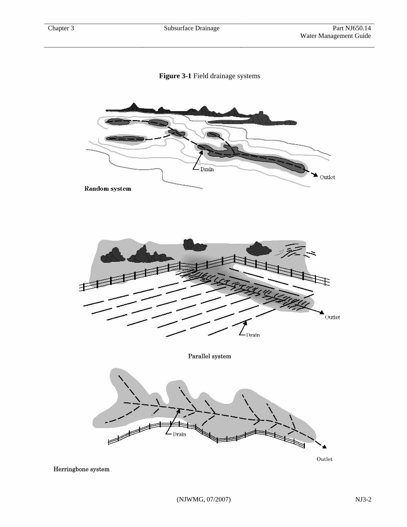
b) Types of systems Relief drains are those installed to remove excess ground water percolating through the soil or to control a high water table. They should systematically lower the water table for an area. The drains may be aligned parallel or perpendicular to the direction of ground water flow. Several general types of system layout or patterns may be considered depending on the topography and nature of the subsurface drainage problem. Random system
A random field drainage system is used where the topography is undulating or rolling and has isolated wet areas. The main drain is generally placed in the lowest natural depression, and smaller drains branch off to tap the wet areas. Because such drains often become outlets for a more complete system established in the higher areas of the field, the depth, location, and capacity of the random lines should be considered as part of a complete drainage system. Generally, the logical location of these drains obviously fit the topography.
Parallel system
The parallel field drainage system consists of laterals that are perpendicular to the main drain. Variations of this system are often used with other patterns. In many cases, the parallel system is desirable because it provides intensive drainage of a given field or area. It can also be used in depressional or low areas that can be graded before installation of the system.
Herringbone system
The herringbone field drainage system consists of laterals that enter the main drain at an angle, generally from both sides. If site conditions permit, this system can be used in place of the parallel system. It can also be used where the main is located on the major slope and the lateral grade is obtained by angling the laterals upslope. This pattern may be used with other patterns in laying out a composite system in small or irregular areas.
Chapter 3 Subsurface Drainage Part NJ650.14 Water Management Guide
(NJWMG, 07/2007) NJ3-2
Figure 3-1 Field drainage systems
Parallel system
Outlet
Herringbone system

Chapter 3 Subsurface Drainage Part NJ650.14 Water Management Guide
(NJWMG, 07/2007) NJ3-3
c) Subsurface drainage design A plan should be made of every subsurface drainage project. The size and detail of the plan will vary depending on the scope of the project, however, all plans should have the same basic information required for the construction of the subsurface drainage system. Considerations (1) Soils
Subsurface drainage is applicable to saturated soil conditions where it is physically and economically feasible to use buried conduits to remove or control free water from the root zone.
The need for and the design of subsurface drainage systems are related to the amount of excess water entering the soil from rainfall; the permeability of the soil and underlying subsoil material; and the crop requirements. In soils with slow permeability that causes water to flow slowly into the drain, the drains must be closely spaced. Consequently, installation may be considered too expensive for use of subsurface drains.
Soils must have sufficient depth and permeability to permit installation of an effective and economical subsurface drainage system. Some sandy soils and peat and muck have large pore spaces that allow rapid movement of water. Wetness occurs in these soils because of a high water table, particularly in the spring, late in summer, or during the irrigation period. For maximum crop yields, the wetness problem must be corrected by drainage. These soils can be successfully drained.
Some fine sand soils have insufficient colloidal material to hold the sand particles together. This can cause excessive movement of the particles into the drains. Special precautions, such as filters or envelopes, are often required.
In highly permeable, coarse sands and some peat soils, excessive lowering of the water table causes
a moisture deficiency during periods of drought. Such soils have limited capillary rise and are unable to deliver water up into the plant root zone of certain crops if the water table falls much below the root zone. Water table control systems should be used for these conditions.
Other soil conditions make construction of drains hazardous or impractical. In some soils, boulders or stones make drainage costs prohibitive. In others, the topsoil is satisfactory, but it is underlain by unstable sand at the depth where drains should be installed, thus making installation more difficult.
(2) Biological and mineral clogging
The ferrous iron content of the ground water flowing into a drain is a reliable indicator of the potential for ochre development. Soluble ferrous iron flowing in ground water enters a different environment as it approaches the drain and passes through the drain envelope. If the level of oxygen is low, certain filamentous and rod-shaped bacteria can precipitate insoluble ferric iron and cause its incorporation into the complex called ochre. The amounts of iron in ground water that can stimulate bacteria to produce ochre can be as low as 0.2 ppm.
Laboratory and field methods are available to estimate the ochre potential for a given site. Of particular importance is whether ochre may be permanent or temporary. Temporary ochre occurs rapidly, usually during the first few months after drain installation. If the drains can be cleaned or maintained in functional order, the ochre problem may gradually disappear as the content of iron flowing to the drains is reduced. Such soil environments must be low in residual organic energy sources to prevent the continual release of iron during short-term flooding.
Permanent ochre problems have been found in profiles with extensive residual iron, such as cemented iron sub-horizons or rocks, and from iron flowing in from surrounding areas. Many factors influence ochre deposition, including the pH, type, temperature, and reducing conditions of the soil.

Chapter 3 Subsurface Drainage Part NJ650.14 Water Management Guide
(NJWMG, 07/2007) NJ3-4
Certain onsite observations may give clues to potential ochre formation before a drainage system is installed. Surface water in channels may contain an oil-like film that is iron and may contain Leptothrix bacterial filaments. Gelatinous ochre may form on the ditch-banks or channel bottom. Ochre may also form within layers of the soil. Iron concretions, sometimes called iron rocks, are in some areas. The presence of spodic horizons (organic layers) suggests ochre potential; and most organic soils, such as mucks, have some potential for ochre problems.
If a site has potential for ochre deposits, certain planning and design practices should be followed to minimize this hazard to the system. No economical, long-term method for effectively controlling this problem is known. For sandy soils where a filter is necessary, a graded gravel envelope is best, although it can become clogged under conditions of severe ochre potential. When synthetic fabrics were evaluated for ochre clogging, the knitted polyester material showed the least clogging.
A submerged outlet may be successfully used to minimize ochre development with the entire drain permanently under water. The line should be completely under water over its entire length throughout the year. This may require that the drains be on flat grade. The depth of ground water over the drain should be at least one foot.
Herringbone or similar drain designs should have entry ports for jet cleaning.
Use drain pipe that has the largest slots or holes allowed within the limits of drain pipe and envelope standards. Slots or holes should be cleanly cut. (3) Outlet The starting point in planning a subsurface drainage system is normally the location of the outlet. Drains may discharge by gravity into natural streams, constructed open ditches, or into larger existing underground mains. Any of these outlets are suitable if they are deep enough and of sufficient capacity to carry all the drainage water
from the entire drainage system. The adequacy of the outlet should be determined before proceeding with the design of the system.
The outlet ditch must have the capacity to remove the drainage runoff from its watershed quickly enough to prevent crop damage. It should be deep enough to allow at least 6 inches of clearance between the flow line of the drain and the normal low water stage in the ditch when drains are installed at the specified depth.
If existing subsurface drains are used for the outlet, they should be in good condition and working properly. The main drain should have sufficient capacity to handle the proposed drainage system in addition to other systems it serves, and it should be deep enough to permit the new system to be installed at the depth specified.
Where a gravity outlet is not available, pumping can be considered. Additional information can be found in this Guide or in the National Engineering Handbook Part 624, Drainage, Chapter 7. (4) Environment Whether a new drainage system is planned or an existing system is to be restored, consideration must be given to the environmental impacts especially effects on wetlands and water quality. The lateral extent of the drainage system’s influence on lowering the ground water level should be evaluated to ensure that adjacent wetland areas are not impacted. Consider the potential for the rapid removal of applied nutrients in drainage water and possible impacts on downstream water quality. Additional measures to control the drainage rate or efficiency; or management of rate and timing of nutrient applications; may be necessary. Drainage coefficient Drains should have sufficient capacity to remove excess water from minor surface depressions and
Chapter 3 Subsurface Drainage Part NJ650.14 Water Management Guide
(NJWMG, 07/2007) NJ3-5
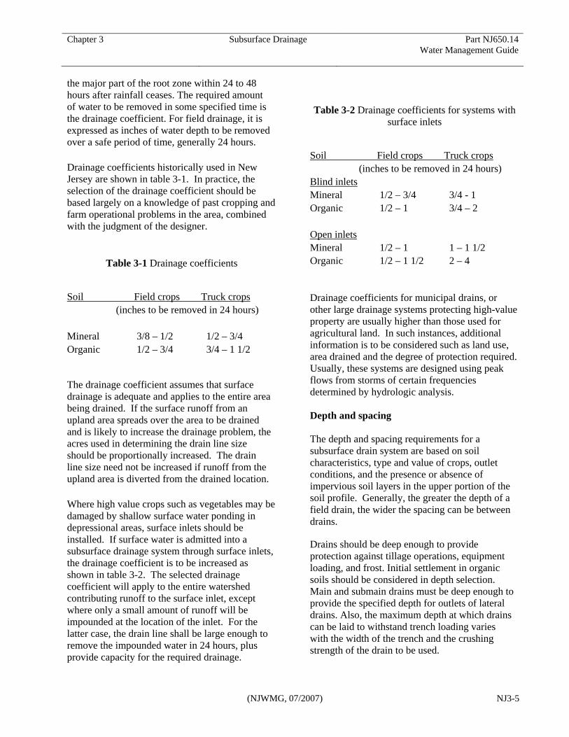
the major part of the root zone within 24 to 48 hours after rainfall ceases. The required amount of water to be removed in some specified time is the drainage coefficient. For field drainage, it is expressed as inches of water depth to be removed over a safe period of time, generally 24 hours. Drainage coefficients historically used in New Jersey are shown in table 3-1. In practice, the selection of the drainage coefficient should be based largely on a knowledge of past cropping and farm operational problems in the area, combined with the judgment of the designer.
Table 3-1 Drainage coefficients
Soil Field crops Truck crops (inches to be removed in 24 hours)
Mineral 3/8 – 1/2 1/2 – 3/4 Organic 1/2 – 3/4 3/4 – 1 1/2 The drainage coefficient assumes that surface drainage is adequate and applies to the entire area being drained. If the surface runoff from an upland area spreads over the area to be drained and is likely to increase the drainage problem, the acres used in determining the drain line size should be proportionally increased. The drain line size need not be increased if runoff from the upland area is diverted from the drained location. Where high value crops such as vegetables may be damaged by shallow surface water ponding in depressional areas, surface inlets should be installed. If surface water is admitted into a subsurface drainage system through surface inlets, the drainage coefficient is to be increased as shown in table 3-2. The selected drainage coefficient will apply to the entire watershed contributing runoff to the surface inlet, except where only a small amount of runoff will be impounded at the location of the inlet. For the latter case, the drain line shall be large enough to remove the impounded water in 24 hours, plus provide capacity for the required drainage.
Table 3-2 Drainage coefficients for systems with
surface inlets
Soil Field crops Truck crops (inches to be removed in 24 hours)
Blind inlets Mineral 1/2 – 3/4 3/4 - 1 Organic 1/2 – 1 3/4 – 2 Open inlets Mineral 1/2 – 1 1 – 1 1/2 Organic 1/2 – 1 1/2 2 – 4 Drainage coefficients for municipal drains, or other large drainage systems protecting high-value property are usually higher than those used for agricultural land. In such instances, additional information is to be considered such as land use, area drained and the degree of protection required. Usually, these systems are designed using peak flows from storms of certain frequencies determined by hydrologic analysis. Depth and spacing The depth and spacing requirements for a subsurface drain system are based on soil characteristics, type and value of crops, outlet conditions, and the presence or absence of impervious soil layers in the upper portion of the soil profile. Generally, the greater the depth of a field drain, the wider the spacing can be between drains.
Drains should be deep enough to provide protection against tillage operations, equipment loading, and frost. Initial settlement in organic soils should be considered in depth selection. Main and submain drains must be deep enough to provide the specified depth for outlets of lateral drains. Also, the maximum depth at which drains can be laid to withstand trench loading varies with the width of the trench and the crushing strength of the drain to be used.
Chapter 3 Subsurface Drainage Part NJ650.14 Water Management Guide
(NJWMG, 07/2007) NJ3-6
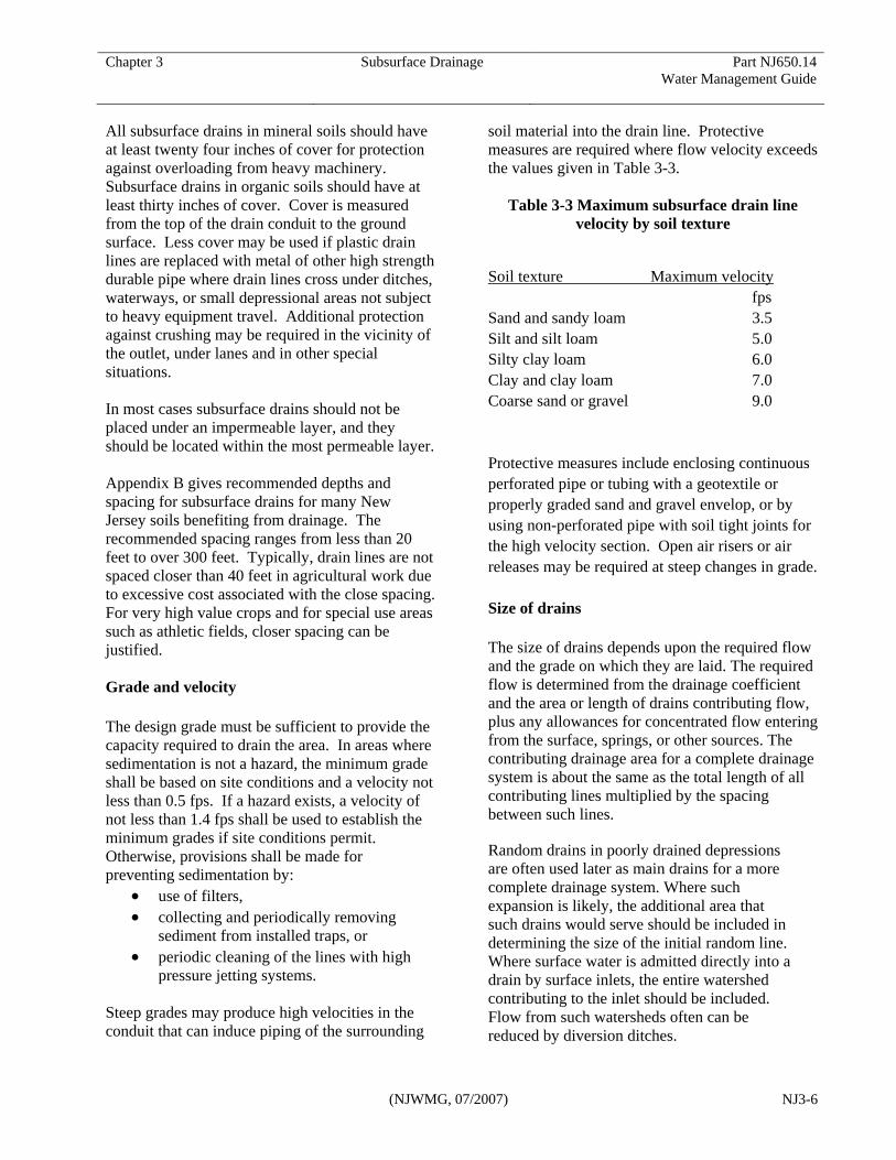
All subsurface drains in mineral soils should have at least twenty four inches of cover for protection against overloading from heavy machinery. Subsurface drains in organic soils should have at least thirty inches of cover. Cover is measured from the top of the drain conduit to the ground surface. Less cover may be used if plastic drain lines are replaced with metal of other high strength durable pipe where drain lines cross under ditches, waterways, or small depressional areas not subject to heavy equipment travel. Additional protection against crushing may be required in the vicinity of the outlet, under lanes and in other special situations. In most cases subsurface drains should not be placed under an impermeable layer, and they should be located within the most permeable layer. Appendix B gives recommended depths and spacing for subsurface drains for many New Jersey soils benefiting from drainage. The recommended spacing ranges from less than 20 feet to over 300 feet. Typically, drain lines are not spaced closer than 40 feet in agricultural work due to excessive cost associated with the close spacing. For very high value crops and for special use areas such as athletic fields, closer spacing can be justified. Grade and velocity The design grade must be sufficient to provide the capacity required to drain the area. In areas where sedimentation is not a hazard, the minimum grade shall be based on site conditions and a velocity not less than 0.5 fps. If a hazard exists, a velocity of not less than 1.4 fps shall be used to establish the minimum grades if site conditions permit. Otherwise, provisions shall be made for preventing sedimentation by:
• use of filters, • collecting and periodically removing
sediment from installed traps, or • periodic cleaning of the lines with high
pressure jetting systems. Steep grades may produce high velocities in the conduit that can induce piping of the surrounding
soil material into the drain line. Protective measures are required where flow velocity exceeds the values given in Table 3-3.
Table 3-3 Maximum subsurface drain line velocity by soil texture
Soil texture Maximum velocity fps
Sand and sandy loam 3.5 Silt and silt loam 5.0 Silty clay loam 6.0 Clay and clay loam 7.0 Coarse sand or gravel 9.0 Protective measures include enclosing continuous perforated pipe or tubing with a geotextile or properly graded sand and gravel envelop, or by using non-perforated pipe with soil tight joints for the high velocity section. Open air risers or air releases may be required at steep changes in grade. Size of drains The size of drains depends upon the required flow and the grade on which they are laid. The required flow is determined from the drainage coefficient and the area or length of drains contributing flow, plus any allowances for concentrated flow entering from the surface, springs, or other sources. The contributing drainage area for a complete drainage system is about the same as the total length of all contributing lines multiplied by the spacing between such lines.
Random drains in poorly drained depressions are often used later as main drains for a more complete drainage system. Where such expansion is likely, the additional area that such drains would serve should be included in determining the size of the initial random line. Where surface water is admitted directly into a drain by surface inlets, the entire watershed contributing to the inlet should be included. Flow from such watersheds often can be reduced by diversion ditches.

Chapter 3 Subsurface Drainage Part NJ650.14 Water Management Guide
(NJWMG, 07/2007) NJ3-7
(1) Main drain The required discharge can be determined using figure 3–3 for a given drainage coefficient and area (acres). The required size of the corrugated plastic drainage tubing can be determined directly from figure 3–4. The size required for all types of drains can be calculated using Manning's equation with the appropriate roughness coefficients (table 3–4). The following example illustrates the use of these charts for the subsurface drainage system shown in figure 3-2. Figure 3–2 Subsurface drainage system
725 ft
Subsurface pipe drain
Table 3–4 Values of Manning's n for subsurface drains and conduits Description of pipe Values of n Corrugated plastic tubing
3 to 8 inch diameter 0.015 10 to 12 inch diameter 0.017 >12 inch diameter 0.020
Smooth plastic, unperforated 0.010 – 0.012 Smooth plastic, perforated 0.010 – 0.012 Annular corrugated metal 0.021 – 0.025 Helical corrugated 0.015 – 0.020 Concrete 0.012 – 0.017 Vitrified sewer pipe 0.013 – 0.015 Clay drainage tile 0.012 – 0.014
Example for main drain (see Figure 3-3):
Given: A tract of land about 640 by 725 feet is to be drained for general crops. The drainage area is 10.65 acres. The drainage coefficient is 3/8 inch in 24 hours (0.0156 inch/hour). A parallel system that has laterals spaced 66 feet apart, requires 4 lines, 660 feet long; 11 lines, 370 feet long; and 1 line, 200 feet long; making a total of 6,910 feet of drain. The main, as shown from a plotted profile, is on a grade of 0.08 percent and is to be corrugated plastic tubing. Required: Size of the corrugated plastic main at the outlet and its capacity.
Using figure 3–3, find 10.65 acres in the 3/8 inch coefficient column under Area Drained to determine the discharge of 0.17 cubic feet per second. Using this discharge, enter figure 14–34 and a slope of 0.08 vertical grade line. The point of intersection lies within the range for an 8-inch drain. The top line of the space marked 8 represents the 8-inch drain flowing full when the hydraulic grade is the grade of the drain. From the

Chapter 3 Subsurface Drainage Part NJ650.14 Water Management Guide
(NJWMG, 07/2007) NJ3-8
intersection of the top of 8-inch range and grade of

Chapter 3 Subsurface Drainage Part NJ650.14 Water Management Guide
(NJWMG, 07/2007) NJ3-9
Figure 3-3 Subsurface drain discharge from drainage coefficient

Chapter 3 Subsurface Drainage Part NJ650.14 Water Management Guide
(NJWMG, 07/2007) NJ3-10
Figure 3-4 Subsurface drain discharge for corrugated plastic pipe
Chapter 3 Subsurface Drainage Part NJ650.14 Water Management Guide
(NJWMG, 07/2007) NJ3-11
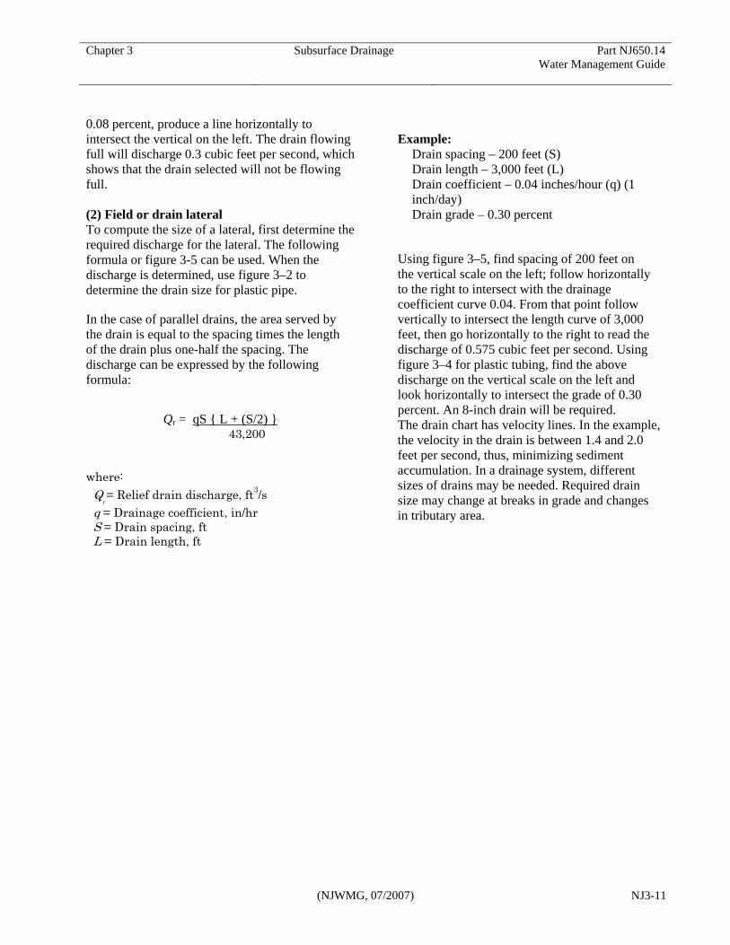
0.08 percent, produce a line horizontally to intersect the vertical on the left. The drain flowing full will discharge 0.3 cubic feet per second, which shows that the drain selected will not be flowing full. (2) Field or drain lateral To compute the size of a lateral, first determine the required discharge for the lateral. The following formula or figure 3-5 can be used. When the discharge is determined, use figure 3–2 to determine the drain size for plastic pipe.
In the case of parallel drains, the area served by the drain is equal to the spacing times the length of the drain plus one-half the spacing. The discharge can be expressed by the following formula:
Qr = qS { L + (S/2) }
43,200 where:
Qr = Relief drain discharge, ft3/s
q = Drainage coefficient, in/hr S = Drain spacing, ft L = Drain length, ft
Example:
Drain spacing – 200 feet (S) Drain length – 3,000 feet (L) Drain coefficient – 0.04 inches/hour (q) (1 inch/day) Drain grade – 0.30 percent
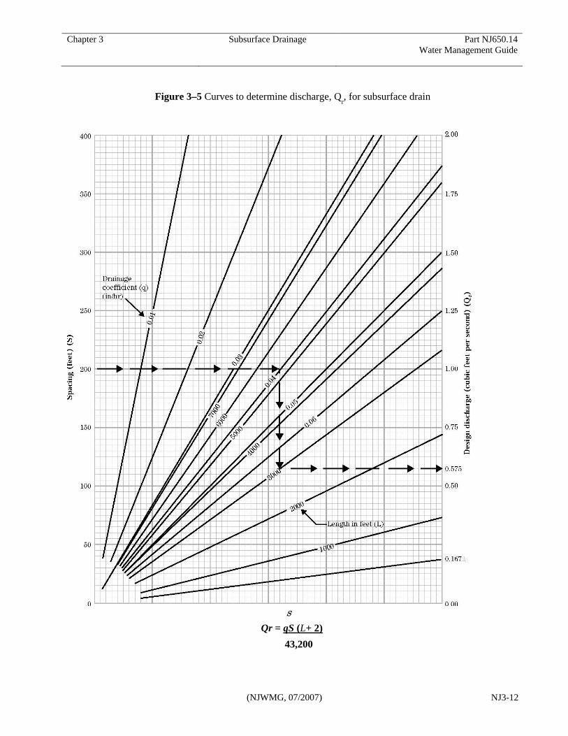
Using figure 3–5, find spacing of 200 feet on the vertical scale on the left; follow horizontally to the right to intersect with the drainage coefficient curve 0.04. From that point follow vertically to intersect the length curve of 3,000 feet, then go horizontally to the right to read the discharge of 0.575 cubic feet per second. Using figure 3–4 for plastic tubing, find the above discharge on the vertical scale on the left and look horizontally to intersect the grade of 0.30 percent. An 8-inch drain will be required. The drain chart has velocity lines. In the example, the velocity in the drain is between 1.4 and 2.0 feet per second, thus, minimizing sediment accumulation. In a drainage system, different sizes of drains may be needed. Required drain size may change at breaks in grade and changes in tributary area.
Chapter 3 Subsurface Drainage Part NJ650.14 Water Management Guide
(NJWMG, 07/2007) NJ3-12
Figure 3–5 Curves to determine discharge, Qr, for subsurface drain
S
Qr = qS (L+ 2) 43,200

Chapter 3 Subsurface Drainage Part NJ650.14 Water Management Guide
(Draft NJWMG, 03/2007) NJ3-13
d) Drain envelope Drain envelope is used here as a generic term that includes any type of material placed on or around a subsurface drain for one or more of the following reasons:
• To stabilize the soil structure of the surrounding soil material, more specifically a filter envelope.
• To improve flow conditions in the immediate vicinity of the drain, more specifically a hydraulic envelope.
• To provide structural bedding for the drain, also referred to as bedding.
Soils in which drains are prone to mineral clogging are commonly referred to as problem soils because the soil particles tend to migrate into the drain. In practice, all very fine sandy or silty soils with low clay content are probable problem soils and will require filter envelopes (fine SP, fine SM, and ML or SM with P.I. less than 7). Finer textured soils, even with high clay content if the soil is considered dispersed, may present clogging problems in addition to being difficult to drain. Drain envelope materials Drain envelope materials used to protect subsurface drains include almost all permeable porous materials that are economically available in large quantities. Based on the composition of the substances used, they can be divided into three general categories: mineral, organic, and geotextile envelope materials.
Mineral envelopes consist of coarse sand and fine gravel. The envelope material may be pit run coarse sand and fine gravel containing a minimum of fines. Properly designed or selected sand-gravel drain envelopes can fulfill all the mechanical, soil stabilizing, and hydraulic functions of a filter envelope.
Organic envelopes include prewrapped loose plant materials, fibers, chips, or granules. The service life and suitability of organic materials as
drain envelopes for subsurface drains cannot be predicted with certainty. Organic matter placed as a drain envelope may also affect chemical reactions in the soil that result in biochemical clogging problems. Where ochre clogging of drains is expected, organic matter should be used with caution. Synthetic materials are geotextile fabrics specifically manufactured for use in drainage and soil stabilization. A geotextile is a permeable, polymetric material that may be woven, nonwoven, or knitted. Geotextiles are made of polyester, polypropylene, polyamide, polystyrene, and nylon. The materials vary in weight, opening size, fiber diameter, thickness, and uniformity.
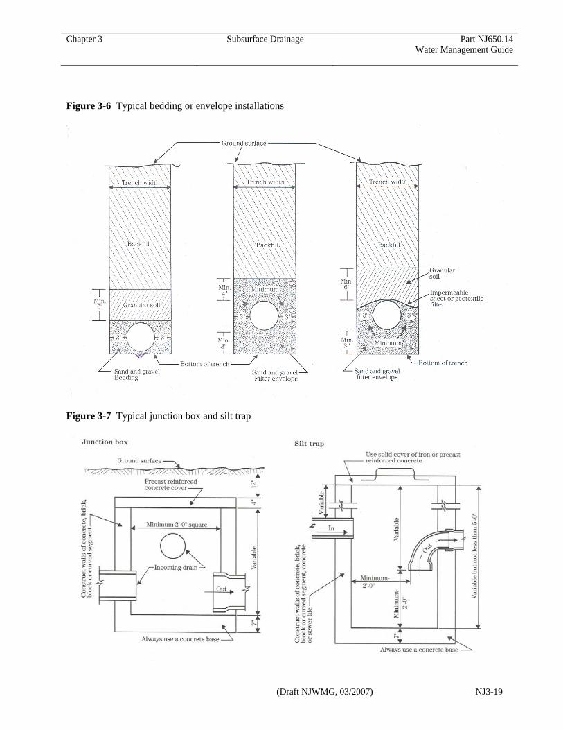
Drain envelope materials are most effective when placed completely around the pipe. Typical drain envelope installations are shown in figure 3–6.
The practice of blinding or covering subsurface drains with a layer of topsoil before backfilling the trench actually provides many humid area drains with permeable envelope material. Humid area surface soils tend to have a well developed, stable, and permeable structure that functions well as a drain envelope. In stratified soils, drains are blinded by shaving the coarsest textured materials in the soil profile down over the pipe.
Design of drain envelopes (1) Sand-gravel filter envelope design The general procedure for designing a sand-gravel filter envelope for a given soil is:
• Make a mechanical analyses of both the soil and the proposed filter envelope material.
• Compare the two particle size distribution curves.
• Use criteria to determine whether the filter envelope material is satisfactory.
The criteria include: • The D
15 (defined below) size of the filter
material should be at least 4 times the diameter of the d
15 of the base material.
(This would make the filter material
Chapter 3 Subsurface Drainage Part NJ650.14 Water Management Guide
(Draft NJWMG, 03/2007) NJ3-14
roughly more than 10 times more permeable as the base material.)
• The D15
of filter material should not be more than 4 times larger than the d
85 of the
base material. (This prevents the fine particles of the base material from washing through the filter material.)
The following gradation limits are recommended:
• Upper limit of D100
is 38 mm (1.5 inches) • Upper limit of D
15 is the larger of 7 times
d85
or 0.6 mm. • Lower limit of D
15 is the larger of 4 times
d15
or 0.2 mm. • Lower limit of D
5 is 0.075 mm (#200
sieve).
D
100 represents the particle size in the filter
material for which 100 percent, by weight, of the soil particles are finer (similarly for D
15 and D
5).
The d85
and d15
represent the particle size in the surrounding base material for which 85 percent and 15 percent, by weight, of the soil particles are finer. In the case of drainage, the base material is the soil.
Procedures for determining filter gradation design limits are found in NEH, Part 633, Chapter 26, Gradation Design of Sand and Gravel Filters.
Research on filter envelopes show that: • If a filter envelope does not fail with the
initial flow of water, it is probably permanently safe.
• The size ratios are critical. • Materials with a D
15/d
85 ratio greater than
nine always fail. • Well graded materials are more successful
than uniform sized materials. • A well-graded gravelly sand is an
excellent filter or filter envelope for very uniform silt or fine uniform sand.
• It is not necessary for the grading curve of the filter envelope to be roughly the same
shape as the grading curve of the soil.
(2) Sand-gravel hydraulic envelope design The criteria for a sand-gravel hydraulic envelope are less restrictive than for a sand-gravel filter envelope as follows:
• Upper limit of D100
is 38 mm (1.5 inches). • Upper limit of D
30 is 0.25 mm (#60 sieve).
• Lower limit of D5 is 0.075 mm (#200
sieve).
Pit run coarse sand and fine gravel containing a minimum of fines often meet these criteria. Sand gradations used for concrete as specified by ASTM C-33 (fine aggregate) will satisfy these hydraulic envelope criteria and will meet the filter envelope requirements for most soils.
(3) Geotextile filter envelope design In filter envelope applications, the geotextile must physically survive installation, allow adequate flow of water, and basically retain the soil on its hydraulically upstream side. Both adequate flow capacity (requiring an open geotextile structure) and soil retention (requiring a tight geotextile structure) are required simultaneously. Therefore, critical geotextile parameters for filter envelope applications are permittivity, survivability, and soil retention. Non-woven geotextiles are recommended for most drainage situations. In general, non-woven geotextiles retain more soil fines than do woven geotextiles. The structure of the mechanically bonded needle-punched fabric helps to decrease the internal clogging potential of the fabric. Non-woven fabrics also have very good oermeability and permittivity characteristics. Minimum requirements for non-woven geotextiles satisfactory for most installations include:
• Tensile strength: 90 pounds, ASTM D 4632
• Bursting strength: 180 psi, ASTM D 3786 • Elongation at failure: >50%, ASTM D
4632 • Puncture: 40 pounds, ASTM D 4833 • AOS: Maximum #40 sieve, ASTM D

Chapter 3 Subsurface Drainage Part NJ650.14 Water Management Guide
(Draft NJWMG, 03/2007) NJ3-15
4751 • Permitivity: 0.70 , ASTM D 4491
e) Appurtenances
Surface inlets
Surface inlets should be used in low areas where surface drainage otherwise cannot be provided. They must be properly constructed to prevent washouts and silting of the line. Surface inlets should be avoided wherever possible. If silt is a hazard, place a silt trap (figure 3–7) at a convenient location immediately downstream from the inlet or use a blind inlet (figure 3–8). Blind inlets allow entry of surface water from small ponded areas into the drain without an open riser. The sand-gravel material for the porous medium must be appropriately designed to keep out sediment and prevent piping of base soil material, yet provide free water movement into the drain. Junction boxes
Junction boxes should be used where two or more main or sub-main drains join or where several laterals join at different elevations. If the junction is in a cultivated field, the box should be constructed so that the top is at least 18 inches below the surface of the ground. It can be capped and covered and its position referenced for future relocation (figure 3–7). Vents and relief wells
Vents, or breathers, are used to alleviate vacuum or negative pressure in the line. Breathers should be used where the line changes abruptly from a flat section to a steep section. Permanent fence crossings are good locations for installation. Relief wells relieve pressure in the line. They should be installed where steep sections change to flat sections unless the flatter section has about 25 percent greater capacity than the steeper section. They should be used on lines that have surface inlets, particularly when such inlets are large (figure 3-9). Outlet protection Where drains outlet into an open ditch or natural
stream, the end of the drainage line should be protected from erosion, damage from periodic submergence, and from entry of rodents into the drain. Protection against erosion can be provided by using a length of continuous, non-perforated, rigid pipe at the outlet. Typical materials include corrugated metal pipe, or smooth PVC pipe. The rigid pipe should be a minimum of ten feet in length, with no more than 1/3 of the pipe length extending from the channel bank. The outlet should be six inches above the normal flow level in the ditch or one foot above the ditch bottom. Drainage systems that outlet into a pond may discharge at the water surface if there is a control structure at the pond’s outlet that provides at least one foot of drop to the downstream channel. When there is a likely fire hazard due to burning vegetation at the outlet, a fire resistant material such as corrugated metal pipe should be used. Headwall structures should be considered where mowing could damage the outlet section. Where ice or floating debris may damage the outlet pipe, the outlet should be recessed from the bank or a headwall structure should be used. Animal guards should be installed on the ends of all outlet pipes. Flap gates, hinged-rod gates, screens, and bar gratings are commonly used. Some different styles are shown in figure 3-10. Flap gates or hinged-rod gates should be used on drains that connect to surface water inlets to allow passage of debris that may enter the system. Where surface water enters the ditch at the location of the drain outlet, some type of structure or precaution is needed to facilitate the transport of the water into the ditch without damage from erosion. The type of structure required is related to the drainage area size, discharge, site topography and soil. For disperse flows that may concentrate as fill settles in the pipe trench, a berm may be constructed across the trench at the ditch bank to divert flow to vegetated areas. For concentrated flows, a stabilized chute or drop structure may be necessary. Generally, drainage systems will not require conduit outlet protection in the form of a riprap apron or preformed scour hole, however, the need

Chapter 3 Subsurface Drainage Part NJ650.14 Water Management Guide
(Draft NJWMG, 03/2007) NJ3-16
should be evaluated where high exit velocities are expected or the system includes surface inlets. f) Installation Trenching and placement Corrugated plastic drainage tubing has relatively little inherent load-bearing strength. Its ability to support soil loads is derived from the lateral pressure induced as the sides of the tubing deflect outward against the soil. Flexible tubing must be installed in the trench in a way that insures good soil support around the conduit. The conduit should not be placed on exposed rock or stones more than 1.5 in. in diameter. Where such conditions are present the trench must be over-excavated a minimum of 6 inches and refilled to grade with a suitable bedding material. The conduit must be placed on a firm foundation to insure proper alignment. If installation will be below a water table or where unstable soils are present, special equipment, installation procedures, or bedding materials may be needed. These special requirements may also be necessary to prevent soil movement into the drain or plugging of the envelope if installation will be made in such materials as saturated fine sands or silts. . For trench installations of corrugated plastic tubing 8 inches or less in diameter, one of the following bedding methods will be specified:
• A shaped groove or 90o V-notch in the bottom of the trench for tubing support and alignment.
• A sand-gravel envelope, at least 3 in. thick, to provide support
• Compacted soil bedding material beside and to 3 in. above the tubing.
For trench installations of corrugated plastic tubing larger than 8 inches, the same bedding requirements will be met except that a semi-circular or trapezoidal groove shaped to fit the conduit will be used rather than a V-shaped groove.
For rigid conduits installed in a trench, the same requirements will be met except that a groove or notch is not required. All trench installations should be made when the soil profile is in its driest possible condition in order to minimize problems of trench stability, conduit alignment, and soil movement into the drain. For trench installations where a sand-gravel or a compacted bedding is not specified, the conduit should be blinded with selected material containing no hard objects larger than 1.5 in. in diameter. Blinder should be carried to a minimum of 3 in. above the conduit. Drain crossings and outlets Special considerations should be made where drains are installed under waterways and roads. Figure 3-11 provides some guidance for these crossings. The figure also provides guidance for drain installation where shallow depth of cover exists at the drain outlet. Alternatives include:
• adding fill to obtain the required minimum depth of cover,
• installing a rigid pipe rated for less than two feet of cover, or
• excavating an open ditch back to a point where the required minimum depth of cover can be provided.
Protection against biological clogging 1) Roots Water-loving trees, such as willow, red maple, elm, poplar, and cottonwood, should be avoided when locating a drain line. Roots will clog the drain if they are allowed to enter. A minimum distance of 100 feet should be maintained from these trees unless non-perforated pipe is used. Drain lines should be located a minimum of 50 feet from other types of trees. When the proximity to trees cannot be avoided and drainage must still be provided, a sand and gravel envelope should be installed along the length of non-perforated pipe. Where crop or grass roots may cause clogging, facilities may be installed to provide a means for

Chapter 3 Subsurface Drainage Part NJ650.14 Water Management Guide
(Draft NJWMG, 03/2007) NJ3-17
submerging the conduit or elevating the water table above the drain to inhibit root growth from extending to the system. 2) Iron ochre If drains are to be installed in sites where iron ochre problems are likely to occur, provisions should be made to provide access for cleaning the lines. Each drain line should outlet directly into an open ditch and/or should have entry ports as needed to provide access for cleaning equipment. Riser pipes for flushing the line shall be provided at intervals not to exceed 500 feet. Drain cleaning provisions should be installed in such a way that the drains can be cleaned in an upstream or rising grade direction. If possible, drains in ochre-prone areas should be installed during the dry season when the water table is low and the iron is in its insoluble form. Where possible, in areas where the potential for ochre problems is high, protection against ochre development can be provided by designing an outlet facility to ensure permanent submergence of the drain line. g) Safety Trenching, particularly in saturated soils, can be hazardous. Failure of trench walls can occur suddenly and without warning. Because of this, the federal Occupational Safety and Health Administration (OSHA) has developed specific standards, practices, and procedures governing trench excavation. Contractors are familiar with these regulations and must adhere to the requirements. No excavation should take place on a project site until a utility mark-out has been completed. Buried utilities, particularly gas lines, can be extremely dangerous. Landowners or contractors must call the State buried utility location service prior to construction. On-farm utility lines, such as irrigation mains, may not be identified by the service. In such cases, landowner knowledge, previous plans, and field evidence must be relied upon. h) Maintenance Maintenance of drainage systems, while not
extensive, is very important for operation of the system. If the subsurface drains are working properly, water will stand in the field for only a short time after a heavy rainfall. If water stands for a few days, the drain may be partly or completely blocked. Regular inspection of the drainage system is essential. Flow rates in surface inlets, junction boxes, manholes, or at the outlet should be monitored after heavy rains or in the spring when ground water levels tend to be higher. Changes in flow can indicate blockages. Prompt repair will keep the system serviceable. Many subsurface drainage systems fail due to sediment buildup and blockage of the outlet. Ditches should be cleaned and additional land treatment measures applied where excessive sedimentation occurs. Holes or depressions may occur over drain lines indicating that soil has been displaced into the line. This can occur at joint separations or where the drain line has been crushed or damaged. Again, prompt repairs should be made. Drainage systems in fine sands or silty soils should be checked frequently following installation for signs of sediment, as the newly disturbed soil lacks structure and can be easily displaced. In time as finer particles are removed, coarser ones may be retained at the perforation, eventually slowing the rate of displacement or piping. Subsurface drainage systems have an estimated service life of 20 years. This can be achieved and prolonged through proper maintenance. Standardized operation and maintenance plans have been developed for subsurface drainage practices and can be found in the NRCS New Jersey electronic Field Office Technical Guide.

Chapter 3 Subsurface Drainage Part NJ650.14 Water Management Guide
(Draft NJWMG, 03/2007) NJ3-18
Chapter 3 Subsurface Drainage Part NJ650.14 Water Management Guide
(Draft NJWMG, 03/2007) NJ3-19
Figure 3-6 Typical bedding or envelope installations
Figure 3-7 Typical junction box and silt trap

Chapter 3 Subsurface Drainage Part NJ650.14 Water Management Guide
(Draft NJWMG, 03/2007) NJ3-20
Figure 3-8 Blind surface inlet

Chapter 3 Subsurface Drainage Part NJ650.14 Water Management Guide
(Draft NJWMG, 03/2007) NJ3-21
Figure 3-9 Vent or relief well Figure 3-10 Typical animal guards
Figure 3-11 Drain crossings and outlets

Chapter 3 Subsurface Drainage Part NJ650.14 Water Management Guide
(Draft NJWMG, 03/2007) NJ3-22
Figure 3-11 Drain crossings and outlets (continued)