Embed Size (px)
Citation preview
18-BH15D7-5
© 2006 American Standard Inc. All rights reserved
Model:TAYPLUS103A
INSTALLER'SGUIDEALL phases of this installation must comply withNATIONAL, STATE AND LOCAL CODES.
Hybrid Comfort™ SystemIMPORTANT — This Document is customer property and is to remain with this unit. Please return to service information pack upon completion of work.
LibraryProduct SectionProductModelLiterature TypeSequenceDateFile No.Supersedes
INSTALLATION OF BONNET THERMOSTAT THT01248(BAYSEN03ATEMPAA) ON ALL OIL FURNACES
"A" COIL APPLICATION (UPFLOW)1. Remove the front cover panel from the "A" coil enclosure.2. Select a location to make a 1-1/2" hole for the bonnet
thermostat to pass through (see figure 2) in front of the coilbaffle of "A" coil.
3. The location of the 1-1/2" hole should be on a vertical line(plane) to the top of the "A" coil and approximately 4"- 6"down from the front end of the coil.
4. With the template provided make the 1-1/2" hole in the coilbaffle and install the bonnet thermostat with the screwsprovided in the kit.
5. Drill a 3/8" hole in the front cover panel for field wiring andinstall the grommet provided with this kit.
6. Connect the bonnet thermostat leads in the Plus One ControlCenter through the grommet. (See hookup diagram).
7. Replace the front cover panel on "A" coil enclosure andsecure.
"A" COIL APPLICATION (DOWNFLOW)1. Select a location on the air entering side of the coil enclosure
to make a 1-1/2" hole for the bonnet thermostat to passthrough (see Figure 1, page 2).
2. The location of the 1-1/2" hole should be on a horizontal line(plane) to the top of the "A" coil. The bonnet thermostatcannot be in contact (touching) the coil.
3. With the template provided, make the 1-1/2" hole in the coilenclosure and install the bonnet thermostat with the screwsprovided .
GENERALThe Plus One system was designed to combine warm air furnaces(indoor units) with heat pumps for maximum comfort and energyefficiency during the entire year.This is compatible only with furnaces having 24V transformers atleast 35 VA.The control center enclosure is made of galvanized steel, with anattractive decorative logo on the front panel.This enclosure is 9-3/16" x 7-1/8" x 2-1/2" in size. When thecover is removed, the components are readily accessible for fieldhook-up or service. All field electrical connections are toterminal board, or wire nuts (field supplied). This assembly canbe mounted in any position.
INSPECTION1. Unpack the Plus One Control Center and remove cover.
Included inside are:Control Box AssemblyInstaller's Guide
2. Check for any shipping damage. If there is any, report it to thecarrier immediately.
3. The field electrical connections and wiring must be done inaccordance with the "National Electrical Code" and mustcomply with local electrical codes.
4. Minimum gauge 18 AWG thermostat wire.
SYSTEM USAGE AND INSTALLATIONThis system uses a heat pump outdoor section with an indoorheat pump coil, a Plus One Control Center and a warm airfurnace.The Plus One Control Center as shipped from the factory is foroperation in the "non-restricted" mode. For "restricted" opera-tion, field wire in accordance with appropriate diagram (includedin these instructions). TAYSTAT250A is required.1. The indoor coil must be installed on the supply side of the
furnace.2. The Plus One Control Center is installed in close proximity to
the furnace.3. The outdoor thermostat (when used in restricted operation
only) is installed in the outdoor section in accordance withTAYSTAT250A installation requirements.
NOTE: For Load Shedding in the heating cycle, use the restrictedhook up diagram. The utility company's load shedding relay willbe wired in place of the ODT as shown. The utility company's relaymust be a SPDT switch type.
NOTE: Do not connect wires to the W terminal at the comfortcontrol terminal #1 at ODT if utility company requires lockout(restriction) of gas furnace at an outdoor temperature abovethe setting on the ODT. Emergency heat cycle and furnaceblower will come on if the comfort control is in EmergencyHeat mode.
INSTALLER'S GUIDE
2
system, and the heat pump cannot handle the load, when thetemperature in the room drops approximately 1-1/2 degreesfurther, second stage heat is called for. Second stage turns theheat pump off and simultaneously brings the furnace on. Thefurnace will now satisfy the second stage only. The first stage ofthe comfort control is still calling. After a minimum delay of 45seconds, the heat pump will resume operation. If the indoortemperature continues to rise, the comfort control will be satis-fied. If indoor temperature does not continue to rise but falls, thesecond stage will call and bring on the gas furnace again.Changing the comfort control to the Emergency Heat Modeconverts the system to "furnace only" operation.
RESTRICTED MODE - (Requires TAYSTAT250A)The ODT change over must be at or above the applicationbalance point of the system. The heat pump alone cannot handlethe load at outdoor temperatures below the application balancepoint.At any temperature above the setting of the ODT, the heat pumponly will operate when called for by the first stage of the comfortcontrol. When the outdoor temperature drops below the setting ofthe outdoor thermostat, the call for heat goes to the furnace andthe heat pump is cut off. When the outdoor temperature risesabove the setting of the outdoor thermostat, the system returns toheat pump (only) operation.Changing the comfort control to the Emergency Heat Modeconverts the system to "furnace only" operation.
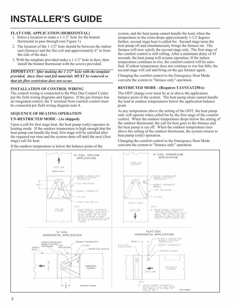
"A" COIL HORIZONTAL APPLICATION
FRONT COIL BAFFLE
"A" COIL
BONNET THERMOSTAT
COILENCLOSURESUPPLY
DUCT
"A" COIL UPFLOWAPPLICATION
SUPPLY DUCT
A" COIL DOWNFLOWAPPLICATION
NOTE 3
3.
NOTE 2
2.
FLAT COIL HORIZONTAL APPLICATION
NO
TE
1
CLASS 2 LOW VOLTAGEWIRING TO SYSTEMCONTROLLER
SEE NOTE 1 ABOVE
HORIZONTALFURNACE
(from 146682)
FLAT COIL APPLICATION (HORIZONTAL)1. Select a location to make a 1-1/2" hole for the bonnet
thermostat to pass through (see Figure 1).2. The location of the 1-1/2" hole should be between the indoor
unit (furnace) and the flat coil and approximately 6" in fromthe side of the duct.
3. With the template provided make a 1-1/2" hole in duct, theninstall the bonnet thermostat with the screws provided.
IMPORTANT: After making the 1 1/2" hole with the templateprovided, duct, liner and foil materials MUST be removed sothat air flow restriction does not occur.
INSTALLATION OF CONTROL WIRINGThe control wiring is connected to the Plus One Control Centerper the field wiring diagrams and figures. If the gas furnace hasan integrated control, the Y terminal from comfort control mustbe connected per field wiring diagram note 4.
SEQUENCE OF HEATING OPERATIONUN-RESTRICTED MODE - (As shipped)Upon a call for first stage heat, the heat pump (only) operates inheating mode. If the outdoor temperature is high enough that theheat pump can handle the load, first stage will be satisfied afterthe required run time and the system shuts off until the next (firststage) call for heat.If the outdoor temperature is below the balance point of the
INSTALLER'S GUIDE
3
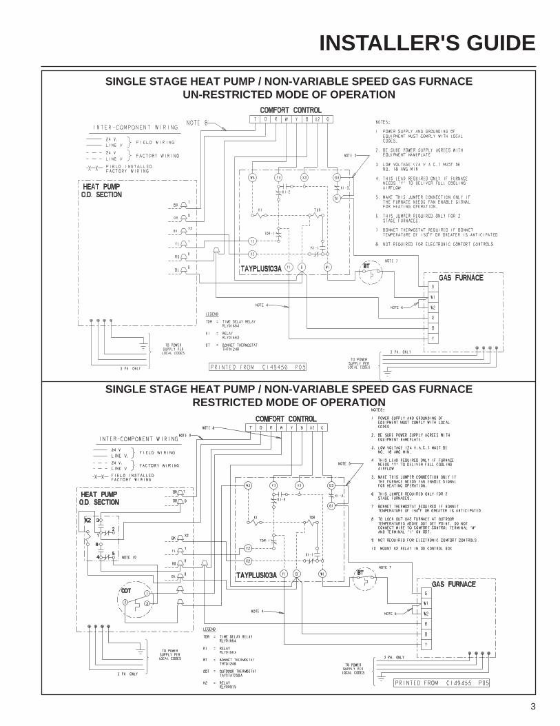
SINGLE STAGE HEAT PUMP / NON-VARIABLE SPEED GAS FURNACEUN-RESTRICTED MODE OF OPERATION
SINGLE STAGE HEAT PUMP / NON-VARIABLE SPEED GAS FURNACERESTRICTED MODE OF OPERATION
INSTALLER'S GUIDE
4
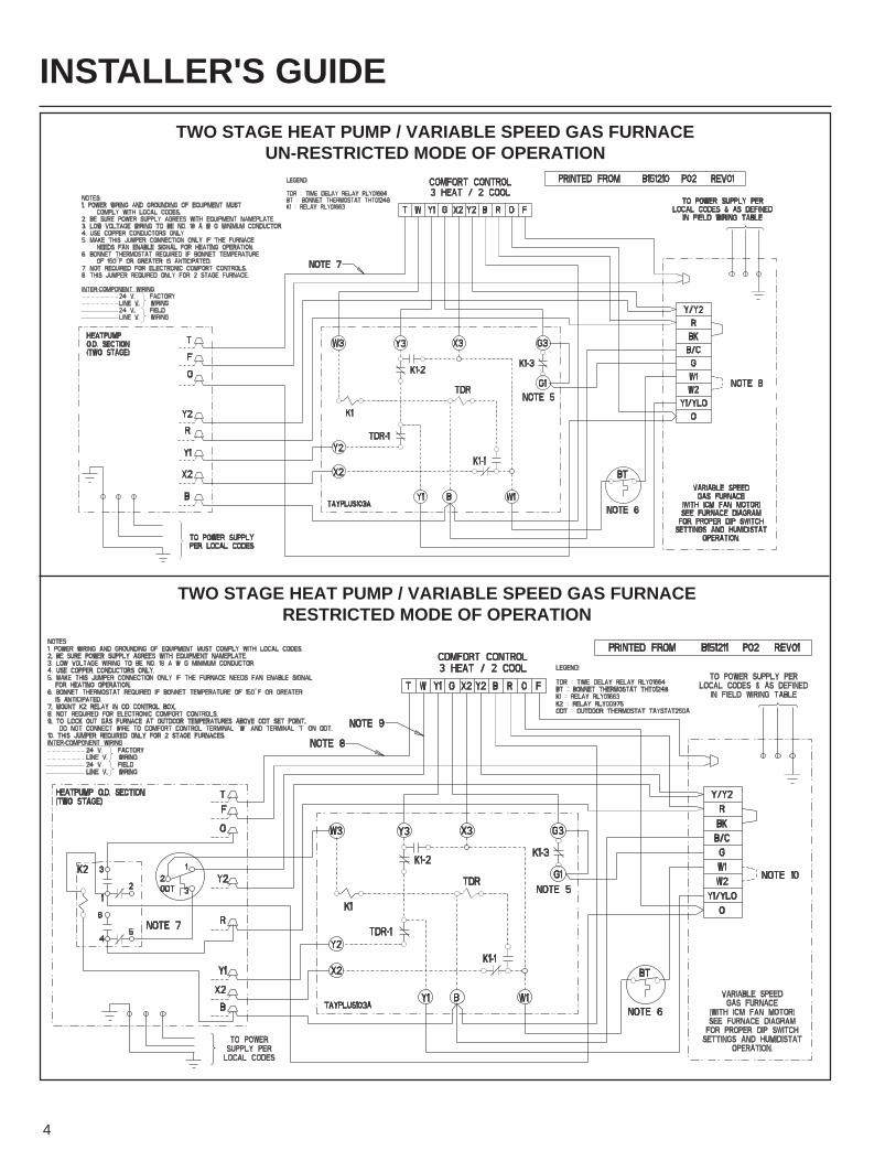
TWO STAGE HEAT PUMP / VARIABLE SPEED GAS FURNACEUN-RESTRICTED MODE OF OPERATION
TWO STAGE HEAT PUMP / VARIABLE SPEED GAS FURNACERESTRICTED MODE OF OPERATION
INSTALLER'S GUIDE
5
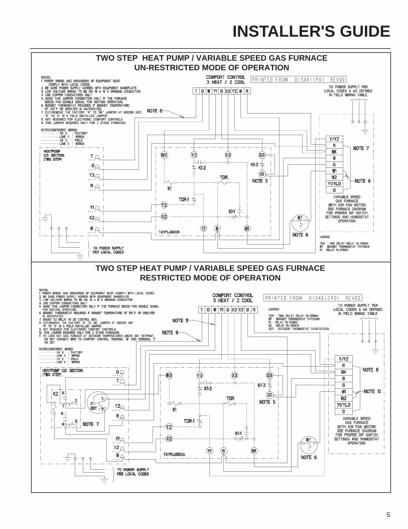
TWO STEP HEAT PUMP / VARIABLE SPEED GAS FURNACEUN-RESTRICTED MODE OF OPERATION
TWO STEP HEAT PUMP / VARIABLE SPEED GAS FURNACERESTRICTED MODE OF OPERATION
INSTALLER'S GUIDE
6
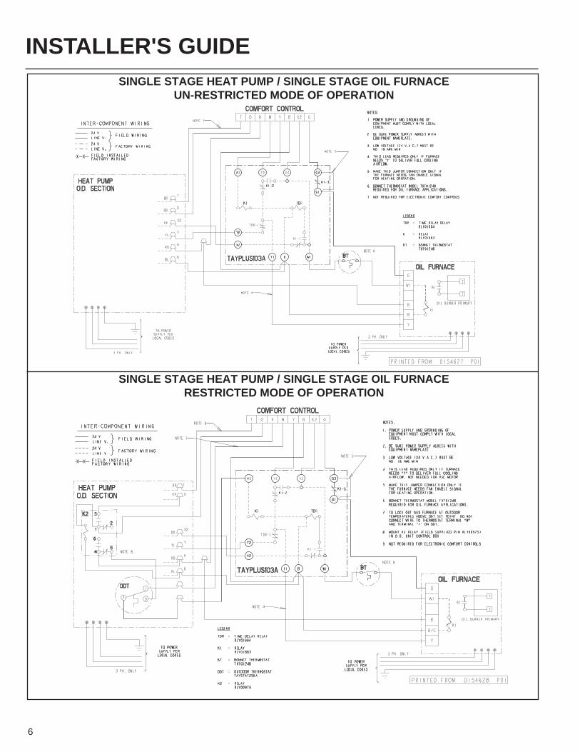
SINGLE STAGE HEAT PUMP / SINGLE STAGE OIL FURNACEUN-RESTRICTED MODE OF OPERATION
SINGLE STAGE HEAT PUMP / SINGLE STAGE OIL FURNACERESTRICTED MODE OF OPERATION

INSTALLER'S GUIDE
7
TWO STAGE HEAT PUMP / VARIABLE SPEED OIL FURNACEUN-RESTRICTED MODE OF OPERATION
TWO STAGE HEAT PUMP / VARIABLE SPEED OIL FURNACERESTRICTED MODE OF OPERATION
INSTALLER'S GUIDE
8
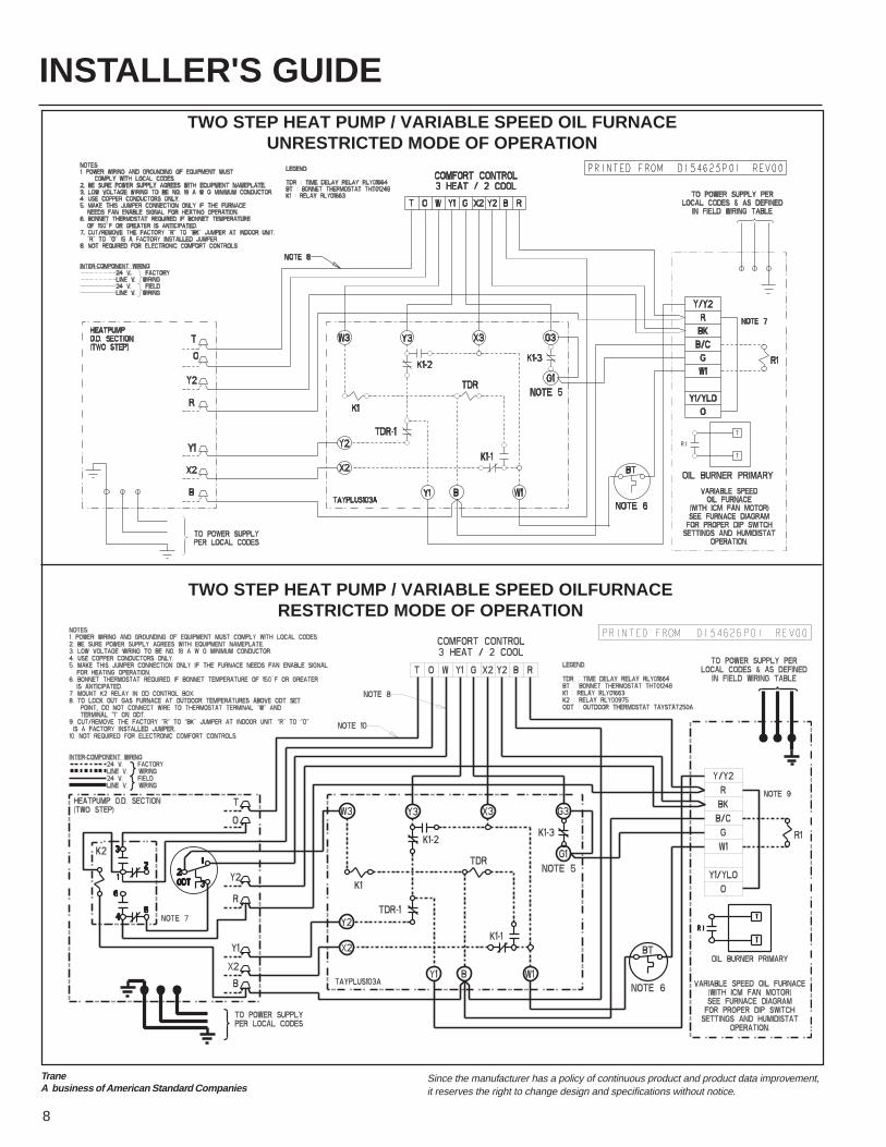
TWO STEP HEAT PUMP / VARIABLE SPEED OIL FURNACEUNRESTRICTED MODE OF OPERATION
TWO STEP HEAT PUMP / VARIABLE SPEED OILFURNACERESTRICTED MODE OF OPERATION
TraneA business of American Standard Companies
Since the manufacturer has a policy of continuous product and product data improvement,it reserves the right to change design and specifications without notice.