Embed Size (px)
Citation preview

Manual6030-2October, 1985SupersedesManualSU-6130-2, Dated 5 /62
Installation & Maintenance Manual
Low VoltagePower Circuit Breakers
•INSTALLATION •OPERATION •MAINTENANCE
TYPESDS-206DS-206SDSL-206DS-416DS-416S
DSL-416DS-420DS-632DS-840
Fuse Trucks forDS-632 and DS-840

LOW VOLTAGEPOWER CIRCUIT BREAKERS
INSTRUCTIONMANUAL 6030-2 CLASS
6 0 3 0
TABLE OF CONTENTS
Description Page
IntroductionGeneral Description
Basic Breaker AssemblyArc ChutesOptional ComponentsAccessoriesSpecial Circuit Breakers: DS-206S and DS-416S
Safety Features .Recommended Safety PracticesSection 1 - Receiving, Handling, and Storing . . .
Receiving and HandlingStoringWeights: Circuit Breakers and Fuse Trucks
7101010101010111213
1.0 131.1 131.2 13
Section 2 - Preliminary Examination2.0 General
1416
Independent Manual and Power-Operated BreakersClosing FacilitiesTripping FacilitiesLevering Device
2.1 162.1.1 162.1.2 162.2 16
Section 3 - First Lift Breakef Onto Drawout Rails3.0 General
1717
Setting the Rails in Front of the CompartmentLifting the Breaker
3.1 173.2 17
Section 4 - Basic Operating Instructions4.0 General
1919
4.1 Levering DeviceCharge the Closing SpringsClose the BreakerOpen the BreakerPlace the Breaker in the TEST Position . .Place the Breaker in the CONNECT PositionRemove the Breaker for Final Inspection .Final InspectionAmptector SettingsPlace the Breaker in Service
194.2 194.3 20
204.44.5 214.6 214.7 21
214.84.9 214.10 21
Section 5 - Description and Explanation of Operation5.0 General
2222
5.1 The Operating Mechanism and How It WorksPower Operated MechanismExplanation of Spring Charging Mechanism for Power Operated
Breakers
22235.1.1
5.1.223245.1.2.1 Power Operation
5.1.35.1.4
30Manual-Operated MechanismsExplanation of Spring Charging Mechanism for Manually Operated
Breakers 30
u *n SQUARE ]] COMPANY 1©Square D Company, 1965

LOW VOLTAGEPOWER CIRCUIT BREAKERS
INSTRUCTIONMANUAL 6030-2CLASS
6 0 3 0
TABLE OF CONTENTS (cont'd.)Description Page
Circuit Breaker Closing MechanismCircuit Breaker Tripping or Opening Mechanism
5.1.55.1.65.1.6.1 Miscellaneous Details
323334
5.1.7 Mechanical Interlocking, Description and Explanation of Operation .5.1.7.1 The REMOVE Position5.1.7.2 The DISCONNECT Position5.1.7.3 The TEST Position5.1.7.4 The CONNECT Position5.1.8 Detailed Explanation of Mechanical Interlock System5.1.8.1 Spring Discharge Interlock5.1.8.2 Connected Breaker Manual Close Interlock5.1.8.3 Breaker Equipped for Electric Lockout5.1.8.4 Closed Breaker Interlock5.1.8.5 Padlocking Provision
3637373738384042434343
45Section 6 — Circuit Breaker Pole Units, Description and Operation6.0 General 45
456.1 Moving Contact Sub-Assemblies .Stationary Contact Sub-Assemblies 476.2
60Section 7 - Arc ChuteGeneral . . 607.0
Section 8 - Circuit Breaker Automatic Tripping System . .8.0 General8.1 The Amptector II Trip Unit
The Amptector I Trip Unit8.2.1 Ground Protection
Making Current Release (Discriminator)Servicing of Amptector Trip UnitActuatorSensors
8.7 Optional Accessories8.7.1 Undervoltage Trip Attachment8.7.2 Overcurrent Trip Switch8.7.3 High Load Switch (available with Amptector I only)8.7.4 Latch Check Switch8.7.5 Auxiliary Switches8.7.6 Amptector Trip Unit Test Kit8.7.6.1 General . . .8.7.6.2 Description8.7.6.3 Operation
626263
8.2 6468
8.3 688.4 69
698.5708.670717172737374747474
Section 9 - DSL Circuit Breakers and Fuse Trucks9.0 General9.1 DSL Current Limiters9.2 Blown Limiter Indicator9.3 Fuse Trucks9.3.1 Installing Fuse Trucks9.3.2 Replacing Fuses9.3.3 Blown Fuse Indicator
7676767677787878
**"*'( ©
u a *-
SQUARE ]] COMPANY2

LOW VOLTAGEPOWER CIRCUIT BREAKERS
INSTRUCTIONMANUAL 6030-2 CLASS
6 0 3 0
TABLE OF CONTENTS (cont’d.)l
PageDescription
80Section 10 - Fixed Breakers
80Section 11 - Drawout Dummy Elements
81Section 12 - Inspection and Maintenance12.0 General12.1.1 When to Inspect12.1.2 What to Inspect12.1.2.1 DS-206, DS-206S, DS-416, DS-416S and DS42012.1.2.2 DS-632 and DS-84012.1.3 Replacement of Contacts12.1.3.1 DS-20612.1.3.2 DS-416, DS-416S, DS420, DS-632 and DS-84012.1.4 Arc Chutes12.1.5 General Inspection12.2 Factory Adjustments12.2.1 Trip Latch Overlap . . .12.2.2 Breaker Open Position Stop (DS632 only) . . .12.2.3 Moving Contact Adjustment12.2.4 Levering Mechanism12.3 Lubrication12.3.1 Frequency12.3.2 Location and Lubricant . . .
818282848585858585858687878787888888
89Section 13 - Renewal Parts13.0 General13.1 Identifying Parts for DS-416S and DS-206S13.1.1 DS-416S Parts13.1.2 DS-206S Parts
89898989
List of Tables
81. Type DS Breaker Ratings2. DSL Breakers - Current Limiting Type Breakers and Combinations3. Approximate Weights4. Sensor and Limiter Ratings
91376
a **D SQUARE COMPANY 3

LOW VOLTAGEPOWER CIRCUIT BREAKERS
INSTRUCTIONMANUAL 6030-2CLASS
6 0 3 0LIST OF ILLUSTRATIONS
Figure Title Page
View Showing Controls on the PanelLeft Side of Breaker with Levering Device Arm in REMOVE
PositionDS-416 Breaker with Front Panel RemovedRight Side Showing Levering Device Arm in TEST PositionRear View Showing Levering Device Arm in CONNECT Position . . .Extending Rails for Breaker RemovalUse of Breaker Lifting AdapterMethod Used to Press Trip Plate and Lower Shutter with One Hand ,
Preparatory to Inserting CrankLevering Device Crank Handle InstalledBreaker Shown Fully Connected and Rails
Stowed Away in Breaker CompartmentFront View of Mechanism (Manual Spring Charge Except for
DS-632/840)Front View of Mechanism (Power-Operated Spring Charge)Rear of Power-Operated MechanismRear View of Mechanism (Left Close Spring Removed)Arrangement of the Principal Parts of a Power-Operated Mechanism.
The Closed Spring is Shown in the Charged PositionFront View Showing Major Parts of the Crank Shaft Assembly
Some Parts are Omitted for ClarityPower-Operated Spring-Charge DetailsCrank Shaft Assembly of Power-Operated MechanismEmergency Spring-Charge on Power-Operated MechanismStandard Schematic and Connection Diagrams for Power-Operated
BreakersPrincipal Parts in a Manually Charged Spring-Operated Mechanism . .Spring-Charging Mechanism on Manual Operated BreakersThese Sketches Show the Four Basic Positions of Breaker and
Linkage with Enlarged View of Trip Shaft and LatchShunt Trip Details Showing Trip Shaft AdjustmentActuatorDS-632 Breaker with Front Panel RemovedBottom View of Breaker Unit Showing Interference Interlock,
Motor Cut-off Switch and Other Details not Visible from Above . .Rear View Showing the Seismic PositionerFront View Showing Close Bar GuardDrawout Unit Position IndicatorRelation of Shutter, Trip Plate, and Trip ShaftRelation of Shutter, Interlock Cam and Levering Device Arms . . . .Close-Release Interlock to Discharge Springs on Levering Out of
Compartment and Conn. Position no Manual Close Interlock . . .Close Interlock to Prevent Efforts to Close a Breaker that is
Already ClosedPadlock Device - Locked Trip Free and Shutter RaisedThree-Pole Assembly of DS-206 Pole Units on FrameThree-Pole Assembly of DS-416/420 Pole Unit on FrameThree-Pole Assembly of DS-632 Pole Units on FrameThree-Pole Assembly of DS-840 Pole Units on Frame
1 142a
152b 153 154 155 176 177
188 189
1810
2211 2212 2213 2314
2415
2516 2617 2718 2719
2820 2921 3022
313223
24 3325 3426a
3526b 3526c 35
362728 39
402930
4131
4232 4333 4534 4635 4736 48
IN< j J k. DSQUARE ]] COMPANY4

INSTRUCTIONMANUAL 6030-2 LOW VOLTAGE
POWER CIRCUIT BREAKERSCLASS
6 0 3 0LIST OF ILLUSTRATIONS (cont’d.)
TitleFigure Page
Type DS-206 Pole Unit Assembly - Front ViewType DS-206 Pole Unit Assembly - Rear ViewType DS-416 Pole Unit Assembly - Front ViewType DS-416 Pole Unit Assembly - Rear ViewType DS-420 Pole Unit Assembly - Front ViewType DS-420 Pole Unit Assembly - Rear ViewType DS-632 Pole Unit Assembly - Front ViewType DS-632 Pole Unit Assembly - Rear ViewType DS-840 Pole Unit Assembly - Front ViewType DS-840 Pole Unit Assembly - Rear ViewMoving and Stationary Contact Details DS-206Moving and Stationary Contact Details DS-416Moving and Stationary Contact Details DS-420Moving Contact Details DS-632Stationary Contact Details DS-632Moving Contact Details DS-840Stationary Contact Details DS-840Breaker with Barrier Removed to Show Mounting of Arc Chutes . . .DS-206 Arc Chute with DetailsDS-206S/DS-416/DS-416S/DS-420 Arc Chute with DetailsDS-632 Arc Chute with DetailsDS-840 Arc Chute with DetailsSchematic Illustration of Tripping SystemStandard Amptector II-A Solid-State Trip UnitAmptector II-A Trip Unit with Front Cover RemovedOptional Amptector I-A Solid-State Trip UnitAmptector I-A Trip Unit with Front Cover RemovedTrip ActuatorDS-840 Breaker with Front Panel RemovedDS-840 Breaker Rear View Showing SensorsUndervoltage Trip DeviceUndervoltage Trip Device OperationOvercurrent Trip SwitchOvercurrent Trip Switch OperationHigh Load SwitchLatch Check SwitchLatch Check Switch OperationAuxiliary Switch Construction DetailsAmptector Trip Unit Test KitTest Kit in OperationDSL-206 Breaker Side ViewDSL-206 Breaker Front View (DSL-416 is Similar)DSL-416 Breaker Side ViewBlown Limiter IndicatorDS-3200 Fuse Truck Front ViewDS-3200 Fuse Truck with Front Cover RemovedDS-4000 Fuse Truck Side ViewContacts and their Adjustment, DS-206 BreakerContacts and their Adjustment, DS-416/420 BreakerContacts and their Adjustment, DS-632 Breaker
37 4938 5039 5140 5141 5142 5143 5244 5245 5246 5247 5348 5449 5550 5651 5752 5853 5954 6055 60
605657 6058 61
62596360
61 6362 6463 6564 6965 7066 7067 7168 7169 7270 7271 7272 7373 7374 7375 7476 7577 7678 7779 7780 7881 7882 7983 7984 8185 8286 83
t* iH 7 0i*
D SQUARE COMPANY 5

LOW VOLTAGEPOWER CIRCUIT BREAKERS
INSTRUCTIONMANUAL 6030-2CLASS
6 0 3 0
LIST OF ILLUSTRATIONS (cont’d.)
Figure Title Page
87 Contacts and their Adjustment, DS-840 BreakerOpen Position Stop and Anti-Rebourd Latch .Levering MechanismLubrication Points on Left Side of MechanismLubrication Points on Right Side of Mechanism
8488 8589 8690 8791 88
* t o
DS Q U A R E D C O M P A N Y6

INSTRUCTIONMANUAL 6030-2 LOW VOLTAGE
POWER CIRCUIT BREAKERSCLASS
6 0 3 0
CAUTION
The circuit breakers described in this bookwere designed and tested to operatewithin their nameplate ratings. Operationoutside of these ratings may cause theequipment to fail, resulting in bodily injuryand property damage.
IntroductionThese instructions cover the description, operation andmaintenance of Square D Type DS and Type DSL LowVoltage AC Power Circuit Breakers and Type DS DrawoutFuse Trucks. These breakers are usually supplied as partof low voltage metal enclosed switchgear of the four-posi-tion drawout type. These instructions apply only to thecircuit breaker and its auxiliary drawout details whichhave been designed as a completely integrated drawoutunit. Type DS Breakers (not DSL) may also be supplied ina fixed mounted version. In this case the sections of thisbook referring to the levering device, position interlocks,and spring discharge interlock will not apply.
DS and DSL Breakers are available for application atvoltages from 208 to 600 Vac; with continuous currentsof 50 to 4000 amps; and with interrupting capabilities upto 200,000 amps. Refer to the breaker nameplate for thecomplete rating information for any given breaker. Break-
conform to ANSI C37.13, C37.16 and C37.50standards.ers
TYPE DS AND DSL BREAKERS ARE PROTECTIVEDEVICES. AS SUCH, THEY ARE MAXIMUM CUR-RENT RATED DEVICES. THEREFORE, THEY SHOULDNOT UNDER ANY CIRCUMSTANCES BE APPLIEDOUTSIDE THEIR NAMEPLATE RATINGS. OPERA-TION OUTSIDE OF THESE RATINGS MAY CAUSETHE EQUIPMENT TO FAIL, RESULTING IN BODILYINJURY AND PROPERTY DAMAGE.
The DS and DSL Circuit Breakers operate on the mag-netic De-ion principle of interruption. In these breakersthe arc rises into a series of insulated steel plates. Theplates break the rising arc into a series of smaller arcs tocool and extinguish them and funnel the heat to ambient The available DS and DSL Breakers and their rated per-
formance capabilities are given in Tables 1 and 2.air.IN
u * »
ID S Q U A R E D C O M P A N Y 7

LOW VOLTAGEPOWER CIRCUIT BREAKERS
INSTRUCTIONMANUAL 6030-2CLASS
6 0 3 0
TABLE 1- DS BREAKER RATINGS<D <2)Inst.
S.C. Interr.RatingSym.Amps
Frame*SizeAmps
SensorRatingsAmps
AcTrip SelectiveS.C. RatingSym.Amps
BreakerType
RangeAmps
VoltageRating
50 25 - 6250 - 12575 - 187100 - 250150 - 375200 - 500300 - 750400 - 800*
600 30,000 30,000100150200 480 30,000 30,000DS206 800 300400600 240 42,000 30,000800*
100 50 - 12575 - 187100 - 250150 - 375200 - 500300 - 750400 - 800*
600 42,000 42,000150200DS206S 800 480 42,000 42,000300400600 240 50,000 42,000800*
100 50 - 12575 - 187100 - 250150 - 375200 - 500300 - 750400 - 1000600 - 1500800 - 1600*
600 42,000 42,000150200300
480 50,000 50,000DS416 1600 400600800
240 65,000 50,00012001600*100 50 - 125
75 - 187100 - 250150 * 376200 - 500300 - 750400 - 1000600 - 1500800 - 1600*
600 50,000 50,000150200300
480 65,000 65,000DS416S 1600 400600800
2401200 65,000 65,0001600*100 50 - 125
75 - 187100 - 250150 - 375200 - 500300 - 750400 - 1000600 - 1500800 - 16001000 - 2000*
150 600 50,000 50,000200300400 480 65,000 65,000DS420 20006008001200
240 65,000 65,00016002000*
65,000 65,0006002400 1200 - 3000
DS632 4803200 65,000 65,0003200* 1600 - 3200*
240 85,000 65,000
600 85,000 85,000
2000 - 4000*4000*DS840 4000 480 85,000 85,000
240 130,000 85,000*Maximum continuous current rating for breaker. Amptector trip unit LongDelay Pick-up should not be set above 100% when using sensor rating equalto frame size.
<D Also short-time ratings.® Short circuit ratings of non-automatic breakers except the DS-840 which is 65,000.
INU * *
SQUARE ]] COMPRNY8

INSTRUCTIONMANUAL 6030-2 LOW VOLTAGE
POWER CIRCUIT BREAKERSCLASS
6 0 3 0
Table 2 — DSL Breakers - Current Limiting Type Breakers and Combinations
Type DSL-206 DSL-416 DSL-632 DSL-840
Frame Size, Amperes 800 1600 3200 4000
Max. Interrupting Rating,RMS Symm. Amp., SystemVoltage 600 or Below 200,000 200,000 200,000 200,000
Notes: DSL-206 and DSL416 include limiters integralwith drawout breaker elements. DSL-632 includes DS-632breaker and DS-3200 drawout fuse truck, in separate in-terlocked compartments. Maximum continuous ratinglimited to 3000A when fuse compartment is above
breaker compartment in same unit. DSL-840 includesDS-840 breaker and DS-4000 drawout fuse truck, in sep-arate interlocked compartments. Maximum interruptingrating limited to 150,000 amperes when 6000A fuses areused.
Maximum voltages at which the interrupting ratings applyare:
Interrupting ratings are based on the standard duty cycleconsisting of an opening operation, a 15 second intervaland a close-open operation, in succession, with delayedtripping in case of short-delay devices.System Voltage Maximum Voltage
208 or 240 254 The standard duty cycle for short-time ratings consists ofmaintaining the rated current for two periods of 1/2second each, with a 15-second interval of zero currentbetween the two periods.
480 508600 635
u*. *•o SQUARE COMPANY 9

LOW VOLTAGEPOWER CIRCUIT BREAKERS
INSTRUCTIONMANUAL 6030-2CLASS
6 0 3 0
AccessoriesGENERAL DESCRIPTION
Square D DS and DSL Circuit Breakers are horizontaldrawout magnetic air circuit breakers. They are designedfor use in Metal-Enclosed Switchgear assemblies havingmaximum voltages of 635 volts AC for DS CircuitBreakers and 600 volts for DSL. They are equipped withspring-stored, energy-closing mechanisms. All primaryinsulation to ground is glass polyester. These breakershave many common features, but they will vary in sizeand detail depending on the specific breaker type numberand ratings. Figure 9 shows Type DS Low Voltage PowerCircuit Breaker installed in a compartment. Figures 78and 79 show Types DSL-206 and DSL-416 CircuitBreakers.
Levering crank is supplied as required. Optional Amp-tector test kit is available for field calibration and testingof Amptector trip units.
Since the major components and the accessories de-pend on the particular type and rating of circuit breaker,packing lists provided with each shipment and moredetailed sections of this instruction book should bereferred to for special information. Any questions aboutthe circuit breakers may be referred to the nearest SquareD Sales Office. When making inquiries about type DS(DSL) circuit breakers always provide the specific typenumber, continuous current rating, mechanism type,applicable order numbers, breaker shop orders or stylenumbers, date of manufacture and other pertinent inform-ation as shown on the circuit breaker and switchgearnameplates. Inquiries can be handled faster when com-plete information is provided with the initial inquiry.
Each DS and DSL Circuit Breaker consists of a basicbreaker assembly, three interrupter assemblies (arc chutes),barriers, and an Amptector solid-state trip unit. DSLbreakers have added current limiters to extend their in-terrupting range to 200,000 amps. Various accessoriesare also provided. Special Circuit Breakers:DS-206S and DS-416S
Basic Breaker Assembly Table 1 gives the interrupting rating of DS-206S as 42,000amperes at 600 volts AC. It is an improved model ofDS-206, which has an interrupting capacity of 30,000amperes at 600 volts AC. Yet, the maximum continuouscurrent rating of 800 amperes is the same for both types.
The basic breaker assembly includes a chassis, a controlpanel, an operating mechanism, a levering-in device,various interlocks, and three insulated pole unit assembliesmounted on a base.
Also, their parts are similar except for these differences:On the front of the breaker are the control items
needed for proper operation of the circuit breaker. Theyare: breaker position indicator, breaker open/closed indi-cator, levering device shutter and shaft , breaker trip plate,closing spring charged/discharged indicator, Amptectortrip test terminal access, Amptector trip controls, closingspring charge handle, close bar and padlock plate.
1. DS-206S uses the three piece base of the DS-4I 6 type,instead of the one piece molded base of the DS-206.2. DS-206S uses the DS-416 arc chute.3. DS-206S main disconnects have 50% more fingers thanthe DS-206.4. DS-206S has twice as many main contacts and arms asthe DS-206.5. The pole unit hinge joint of DS-206S is a forked con-struction or a miniature version of the DS-416 hinge.6. Fifty ampere sensors cannot be installed on DS-206S;but they can be put on DS-206.
Similarly, the parts of DS-416S are almost identicalto those of DS-420. Their interrupting ratings are thesame: 65,000 amperes at 480 volts AC and 50,000 amperesat 600 volts AC. But, the maximum continuous currentrating of DS-420 is 2,000 amperes and for DS-416S it is1600 amperes.
Arc Chutes
Each arc chute contains vertical steel splitter plates, in-sulating spacers and plates. These are all assembled in aninsulating arc chute jacket. The arc chutes mount on topof the pole units and are vented to atmosphere.
Optional Components
Optional components provided upon order are: undervolt-age trip attachment, overcurrent trip switch, high-load tripswitch, latch check switch, auxiliary switches.
Compared to Type DS-416, DS-416S has higher in-terrupting ratings, giving it improved operating flexibility.See Table 1,
I NH I* mSQUARE COMPANY10

INSTRUCTIONMANUAL 6030-2 LOW VOLTAGE
POWER CIRCUIT BREAKERSCLASS
6 0 3 0
Safety FeaturesType DS (DSL) Breakers are manufactured with severalbuilt-in interlocks to reduce hazards and direct properoperating sequences. UNDER NO CIRCUMSTANCESSHOULD THEY BE MADE INOPERATIVE AS THISMAY RESULT IN BODILY INJURY OR PROPERTYDAMAGE.
5. Provisions for Padlocking-Breakers can be padlockedopen to prevent electrical or manual closing. This padlock-ing can also secure the breaker in the connected, test , ordisconnected position by preventing levering.
6. In the CONNECT position automatic mechanical in-terlocking prevents the disconnecting or withdrawal ofa closed breaker. This avoids drawing dangerous, destruc-tive arcs on the disconnecting contacts when the circuitis energized.
1. Positive mechanical indicators on front panel showwhether the breaker is open or closed, and whether theclosing spring is charged or discharged.
2. Closing Spring Automatic Discharge - Mechanical in-terlocking automatically discharges the closing springswhen the breaker is removed from its compartment.
7. In the REMOVE position mechanical interlock systemprevents the closing springs from being charged or remain-ing charged.
3. Mechanical interlocking prevents levering of breakerunless its contacts are open. Contacts cannot be closeduntil the breaker is levered into TEST or CONNECT po-sitions.
8. The integral fuses on Types DSL-206 and DSL-416breakers are inaccessible until the breaker is completelywithdrawn from its compartment, thereby assuring com-plete isolation.
4. Mechanical interlocking prevents closing of breakercontacts while it is being levered into or out of its cell,or while it is standing in any intermediate location be-tween the TEST and the CONNECT positions or the DIS-CONNECT position.
Likewise, the Type DSL-632 and DSL-840 fuses are in-accessible until the separate fuse truck is completely with-drawn and the fuses isolated. The fuse truck is key inter-locked with the breaker to prevent withdrawing or in-sertion unless the breaker is open.
I N411m SQURRE COMPRNY 11

LOW VOLTAGEPOWER CIRCUIT BREAKERS
INSTRUCTIONMANUAL 6030-2CLASS
6 0 3 0
Recommended Safety PracticesType DS circuit breakers are complex electrical devicescontaining high speed, high energy, operating mechanisms.They are designed to operate within the current and volt-age limitations on the breaker nameplate. Do not applythese breakers to systems with currents and/or voltagesexceeding these limits.
chains, etc., to avoid possible damage to parts or droppingthe unit. Use breaker lifting adapter.
8. Use handle on front panel of circuit breaker to move itinto or out of cell. Keep fingers and hands off top, bot-tom or sides of breaker when moving it into or out of cellto prevent bodily injury.
1. To perform work on Type DS Circuit Breakers requirespersonnel with training and experience in high capacitycircuits. Only qualified electrical workers, familiar withthe construction and operation of such equipment and thehazards involved, should be permitted to work on thesecircuit breakers.
9. When operating breaker without arc chutes and bar-riers, keep hands, arms, head and tools out of area wherecontacts travel. Severe bodily injury could result from be-ing struck by the moving contacts either as they open orclose.
2. Only Qualified Persons as defined in the NationalElectric Safety Code should be permitted to assemble, op-erate or maintain these breakers.
10. Be sure circuit breaker contacts are open and closingsprings are discharged before doing maintenance work.
11. Be sure circuit breaker contacts are open and closingsprings are discharged after completing maintenance work.3. The breakers are equipped with various interlocks. DO
NOT MAKE ANY OF THE INTERLOCKS INOPERA-TIVE AS THIS MAY RESULT IN BODILY INJURY ORPROPERTY DAMAGE.
12. Never leave breaker in an intermediate position in acell. Always have the breaker either in the disconnect,test or connected position because control circuits may beeither improperly connected (or disconnected) and maycause electrical failures.
4. Perform insulation dielectric tests on the power carry-ing conductors before installing into the Switchgear toinsure the absence of foreign material and the quality ofthe insulation. 13. Avoid trip-free type operation because it causes more
shock on some parts of breaker than normal closing op-erations. Refer to last paragraph in Item 4.1.5. Never put a breaker into a cell without barriers and arc
chutes.14. Before operating breaker in test position, be sure thatclosing the breaker will not cause another electrically in-terlocked breaker to inadvertently trip.
6. Always be sure that all switch hardware is in place andbolted tightly before inserting breaker into cell.
7. Do not lift breaker with ordinary crane hooks, ropes,
u . nSQUARE COMPANY12

INSTRUCTIONMANUAL 6030-2 LOW VOLTAGE
POWER CIRCUIT BREAKERSCLASS
6 0 30
Section 1 — Receiving, Handling, and Storing
1.0 RECEIVING AND HANDLING NOTE
Receiving and handling of this equipment is covered inSquare D Instruction Book 6030-1 (6035-1) for PowerZone II Low-Voltage Metal-Enclosed Switchgear.
1
Breakers that have been stored or have infrequent opera-tions shall be operated a minimum of five times before be-ing placed in service.
The circuit breakers are packed separately in individualcartons or crates. These packages must be handled withcare to avoid hidden damage to the circuit breakers.Remove them from the crate or carton carefully so as notto cause damage.
1.2 WEIGHTS: CIRCUIT BREAKERS ANDFUSE TRUCKS
Table 3 gives the approximate weights of DS and DSLcircuit breakers. They will vary slightly due to the dif-ferences in functional components of the individual DSBreaker, and the size of the current limiters supplied onDSL Breakers. Fuse truck weights will vary due to dif-ferences of fuse sizes.
Place the breakers on the switchgear extension rails.(See Section 3 before attempting to lift breakers.)Remove the insulating barriers and arc chutes. Inspect thecontact structures to be sure no damage has occurredduring shipment. Replace the arc chutes and insulatingbarriers and proceed as described in Section 2.
Table 3 — Approximate Weights
1.1 STORING Drawout Elements PoundsIf it is necessary to store the equipment before installa-tion, keep it in a clean dry place, protected from dirt andwater and with ample air circulation and heat , if neces-sary, to prevent condensation. Like all electrical appara-tus, these units contain insulation. Although it is of high-est quality, it , like all other insulation, must be protectedagainst dirt and moisture. Refer to Instruction Book6030-1 (6035-1) for details.
DS-206 Circuit Breaker.DS-206S Circuit BreakerDS-416 Circuit Breaker.DS-416S Circuit BreakerDS-420 Circuit Breaker.DS-632 Circuit Breaker.DS-840 Circuit Breaker.DSL-206 Circuit BreakerDSL-416 Circuit BreakerDS-3200 Fuse Truck . .DS-4000 Fuse Truck . .
150160195200200300400200260325430
IQ SQUARE ]] COMPANY 13

LOW VOLTAGEPOWER CIRCUIT BREAKERS
INSTRUCTIONMANUAL 6030-2CLASS
6 0 30
Section 2 — Preliminary Examination2.0 GENERAL The remainder of the drawout element includes the
following auxiliary components:Read these instructions carefully and look at the breakeras it stands out of the compartment before trying tooperate it. Refer to Figures 1, 2, 3 and 4.
1. Interphase insulating barriers which isolate the arcchutes from each other and from ground.
2. Drawout element frame and rollers.The complete drawout element includes the circuitbreaker itself and its auxiliaries. The circuit breakerconsists of four major components: 3. The levering device, for placing the element into its
various positions inside the compartment.1. The operating mechanism.
4. The main disconnecting contacts, for connecting thebreaker to ppwer source and load.2. The contacts, operated by the mechanism.5. The secondary contacts, for connecting the controlcircuits to the electrical operating parts of the element.
3. The arc chutes, which interrupt the arc which alwaysresults from opening the breaker under load or shortcircuit conditions.
6. The interlocks, which increase the safety of operation.4. The *Amptector® solid-state overcurrent tripping sys-tem. 7. Drawout element position indicator.
Fig. 1 View Showing Controls on the Panel•AMPTECTOR® is a registered trademark for the solid state trip unit manufactured by the Westinghouse Electric Corp., Pittsburgh, PA.
•M^ **• mSQUAREn COMPANY14

INSTRUCTIONMANUAL 6030-2 LOW VOLTAGE
POWER CIRCUIT BREAKERSCLASS
6 0 3 0
Fig. 2a Left Side of Breaker with Levering Device Arm inREMOVE Position Fig. 2b DS 416 Breaker with Front Panel Removed
Fig. 3 Right Side Showing Levering Device Arm inTEST Position
Fig. 4 Rear View Showing Levering Device Arm inCONNECT Position
INU 3 *•
S Q U A R E n C O M P A N Y 15

LOW VOLTAGEPOWER CIRCUIT BREAKERS
INSTRUCTIONMANUAL 6030-2CLASS
6 0 3 0
8. Open-Close indicator. On power-operated breakers, the springs are normallycharged by an electric motor. Closing may be doneelectrically by an electro-magnet which lifts the closingspring release latch. Both of these operations can be doneby hand if the control power source fails.
9. Spring charge indicator.
10. The close bar and trip plate.
11. Steel front cover. 2.1.2 Tripping Facilities
The breaker can be tripped open by hand by pushing withthe finger on the trip plate on the breaker panel or thetrip plate on the breaker compartment door (the latter isoperative only when the breaker is in the connectedposition).
12. Nameplate with complete rating information.
The Type DSL-206 and DSL-416 drawout elementsalso include the following components:
1. Current limiters.The breaker can also be tripped electrically by the
following devices:2. Isolating transformers, connected in parallel with thelimiters.
1. Shunt trip device, optional equipment on manuallyoperated breakers.3. Combination “Blown Limiter Indicator” and anti-
single phase device, connected to the isolating transform-ers, actuated by blowing of one or more of the currentlimiters. This device has individual phase indicators and acommon “RESET” button extending through the frontcover.
2. Trip Actuator, energized from the Amptector trip unit.
3. Undervoltage Trip Device (Optional on all breakers)
4. Blown Limiter Indicator (for DSL breakers)Each breaker is equipped with a spring type stored
energy closing mechanism. This mechanism closes thecircuit breaker contacts with the necessary speed andforce, independently of the operator. Basically, theclosing springs must first be charged or cocked before thebreaker can be closed. The springs are then released byreleasing the spring release latch. The breaker is opened byreleasing the tripping latch.
2.2 LEVERING DEVICE
The drawout element has four normal positions in itscompartment, determined by the levering device:
1. The REMOVE position, Figure 2.
2. The DISCONNECT position.2.1 INDEPENDENT MANUAL AND
POWER OPERATED BREAKERS 3. The TEST position, Figure 3.
4. The CONNECT position, Figure 4.2.1.1 Closing Facilities
On manually operated breakers, the closing springs can becharged only by hand , by means of the spring-chargehandle. The actual closing of the breaker is done only byhand-push on the close bar. As optional equipment, theelectrical spring release attachment normally suppliedonly on power-operated breakers can be supplied onmanually operated breakers.
The REMOVE position is the First position in thecompartment as the element is pushed directly by hand asfar as it will go. The DISCONNECT, TEST, and theCONNECT positions are reached only by means of thelevering device. This is hand operated with a removablecrank handle. This handle is placed on the levering deviceworm shaft, which is exposed by depressing the shutter.See Figure 7 on page 18.
mSQUARE COMPRNY16

INSTRUCTIONMANUAL 6030-2 LOW VOLTAGE
POWER CIRCUIT BREAKERSCLASS
6 0 3 0
Section 3 — First Lift Breaker onto Drawout Rails
3.0 GENERAL 3.2 LIFTING THE BREAKER
To examine and become familiar with the constructionand operation of the breaker, it first must be inserted inthe breaker compartment. There are rails provided whichpermit the breaker to be rolled into the compartment sothat it can be examined on all sides and operated. Firstunlatch and open the compartment door.
All lifting should be done only with accessory liftingadapter furnished with each switchgear assembly. DONOT ATTEMPT TO LIFT BREAKER WITH ORDINARYCRANE HOOKS, ROPES, CHAINS ETC., AS VITALPARTS SUCH AS WIRING, BARRIERS AND ARCCHUTE PARTS MIGHT BE DAMAGED. Figure 6 showsa view of the breaker with the lifting adapter in place. Thelifter consists essentially of two sheet steel hooks speciallyshaped to hook under the top edges of the large openingson each circuit breaker side sheet, or in the speciallyprovided lifting lugs on some breakers, and a spreader.Actual lifting may be with a crane, chain block or withthe optional lifting mechanism which can be supplied forthe switchgear. Be sure to align all four breaker rollers oneach drawout rail before releasing lifting adaptor.
3.1 SETTING THE RAILS IN FRONT OFTHE COMPARTMENT
Refer to Figures 5 and 9. There are two rails for eachbreaker compartment which, when not in use, are storedon the inside of the compartment in a back-slopingposition. Withdraw each rail completely and let it downinto a horizontal position, as shown in Figure 5.
Fig. 5 Extending Rails for Breaker Removal Fig.6 Use of Breaker Lifting Adapter
Xu ».»-n SQUARE COMPANY 17

LOW VOLTAGEPOWER CIRCUIT BREAKERS
INSTRUCTIONMANUAL 6030-2CLASS
6 0 30
Fig. 7 Method Used to Press Trip Plate and LowerShutter with One Hand, Preparatory toInserting Crank
? - ;
:v
v.;
'.C.VvV : >i ftmm
i
$§! v..iyilftfi
K
mi1
Hir*.v- yjV*.rv«
Si
kk^MJi;
iv &HipySm1
L:
S'!'!
OR ia
L -.' :
4-v.' S
Fig. 9 Breaker Shown Fully Connected and RailsStowed Away in Breaker Compartment
Fig. 8 Levering Device Crank Handle Installed. ReadSections 2.2 and 4.1 on this Operation
(i 3 > IQSQUARE COMPANY18

INSTRUCTIONMANUAL 6030-2 LOW VOLTAGE
POWER CIRCUIT BREAKERSCLASS
6 0 3 0
Section 4 — Basic Operating InstructionsNOTE4.0 GENERAL
The breaker is now ready for trial mechanical operation.Keep the breaker standing on the compartment rails, outin front of the compartment. Examine it externally forany signs of obvious damage or foreign material. Wheneverything appears to be in order, perform the followingoperations as “dry run” practice. If any malfunctioning isfound during thise operations, see that it is correctedbefore further operations or before placing the breaker inservice.
Further turning effort is useless. The breaker will besecure, even if the stop is only lightly touched. Rememberthis when actually levering the breaker into the connectposition.
Rotation of the crank counterclockwise will turn thelevering device arms to withdraw the unit from the CON-NECT position to the TEST position and then to the DIS-CONNECT and REMOVE positions. Then, when thecrank is removed from the worm shaft, the shutter willremain down and the trip plate will remain trapped by theshutter.
4.1 LEVERING DEVICEThe circuit breaker was shipped in a separate package, andthe levering device was probably left in the REMOVEposition. If not it will be necessary to return it to thisposition. Push in the TRIP plate and depress the shutterover the levering shaft, using one hand, as shown in Figure7, and insert the levering crank as shown in Figure 8. Turnthe crank counterclockwise until the position indicator isin the REMOVE position, at which time the load on thecrank handle increases because a stop has been reached.Now rotate the crank clockwise to simulate levering thebreaker inward toward the CONNECT POSITION.Watchthe movement of the levering device arms. At the start ofcranking the arms are horizontal, with rollers toward therear, Figure 2. As the crank is turned clockwise thelevering device arms rotate downward. When they havemoved approximately 40° from the horizontal, theshutter will rise until it touches the crank socket. Theposition indicator will be opposite “DISC” which is theDISCONNECT position wherein the breaker is held in itscompartment with both main and secondary contactsdisengaged. If the crank is withdrawn, the shutter willclose completely, and the breaker may be locked in thisposition as later described in Section 5.1.8.5 of thisinstruction book. There is very little movement of thebreaker into its compartment between the REMOVE andDISCONNECT positions.
NOTE
If the breaker is levered out from the TEST position tothe REMOVE position with the closing springs charged, atrip-free “closing” operation automatically will be per-formed but the breaker contacts will not close. When apower-operated breaker is removed from cell , it must gothrough a trip-free operation.
4.2 CHARGE THE CLOSING SPRINGS
The closing springs must be charged before the breakercan be closed. To manually charge the closing springs, thelevering device arms must be rotated away from the RE-MOVE position to the TEST position. If charging is at-tempted in the REMOVE position, the closing cam willrotate past the charged position and go through a trip-free“closing” operation , i.e ., the springs will discharge with-out moving the breaker contacts. Do not attempt tocharge the springs in the DISCONNECT position as thesame action may occur. After turning the levering deviceto TEST position, manually charge the springs. On man-ually operated breakers, the springs are charged by a singlestroke downward on the spring-charge handle, rotating itabout 90° toward you until it suddenly becomes veryeasy to move and then tends to run away from your hand.At the same time, you will hear a metallic “click!” as theover center closing spring stop is reached. Note that thespring charge indicator now shows “Spring Charged.”
Continued rotation of the crank in the clockwise direc-tion moves the arms downward to the vertical position,and the indicator will show “TEST” as in Figure 3. Theshutter will rise.
i CAUTION i|Further clockwise rotation of the crank handle rotatesthe arms to the CONNECT position. This is about 65degrees from the test position, as shown in Figure 4. Whenthis position is reached, the crank suddenly becomes hardto turn. At this point, stop turning the crank, as the wormshaft bottoms in the tapped hole of the stop nut.
Do not release the handle before the charging operation iscompleted. To release handle before charging completionwill return handle upwards with such velocity that it maybreak the handle knob CT cause bodily injury.
IXu »m S Q U A R E n C O M P A N Y 19

LOW VOLTAGEPOWER CIRCUIT BREAKERS
INSTRUCTIONMANUAL 6030-2CLASS
6 0 3 0
It is possible to recharge the springs immediately afterclosing the breaker. This results in increased strain on themechanism, and it is recommended that this be done onlyif the operating procedure requires this condition.
}CAUTION
Hold breaker to prevent tilting forward when hand charg-ing closing springs with the breaker on the extended rails.Otherwise, it may topple to the floor and cause bodily in-jury or equipment damage.
NOTE
If closing is attempted with the levering arms in otherthan the TEST or CONNECT positions, with or withoutthe levering crank in place, a trip-free “closing” operationis performed but the breaker contacts do not close. Thistrip free type of operation results in more shock on someparts of the mechanism than normal closing operations.Therefore, this type of operation should be avoided ifpossible.
On power operated breakers, a short spring-charge han-dle is included for emergency operation. This works ona ratchet principle, and requires 10 to 12 pumping opera-tions to completely charge the springs. At this point, thesame metallic “click” will be heard; and the spring chargeindicator will show “Spring Charged.” The handle mustnot be forced beyond this point.
4.4 OPEN THE BREAKERNOTE
The breaker can be opened in the following ways:Power-operated breakers, when being levered into thecompartment, will have the spring-charge motor run andcharge the spring automatically as the TEST position isreached.
1. By hand operation of the trip plate (on the breaker oron the compartment door.)
2. Automatically by overload, short circuit or undervolt-age condition.4.3 CLOSE THE BREAKER
The breaker can be closed only when the following condi-tions are met : 3. Breakers equipped for power operation can be tripped
electrically by a shunt trip device energized by handswitch or relay.1. The closing springs are charged.
For the present purpose of getting acquainted with thebreaker, open it by pushing on the trip plate. Note thatthe breaker position indicator now shows “Breaker-open”,against a green background.
2. The levering arms are in either the TEST position, as inFigure 3 or in the CONNECT position, Figure 4.3. The levering device crank handle has been removed andthe shutter is closed.
NOTE4. Undervoltage trip device (if included) has been ener-gized.
On breakers equipped for power operation, when they arein the compartment and in either the TEST or CONNECTposition, the spring-charge motor normally runs auto-matically and charges the closing springs as soon as thebreaker opens. The closing springs normally remaindischarged while the breaker stands in the closed position.Breakers can be wired so that springs are rechargedimmediately after closing. See Section 5.1.2.1
5. Blown limiter indicator (for DSL breakers only) is reset.
Having met these conditions, close the breaker bypushing on the close bar. Note that the breaker positionindicator shows “Breaker Closed”, against a red back-ground. Also that the spring-charge indicator now shows“Spring Discharged.”
Some power-operated breakers are interlocked to pre-vent manual closing from the close bar on the front panelwhen in the CONNECT position. In this case crank thelevering device to the TEST position to operate. This in-terlock is covered by Section 5.1.8.2.
Now to become better acquainted with the breaker,charge the closing springs, close and open the breakerseveral times. Also, place the levering crank handle on the
U S * nSQUARE COMPANY20

INSTRUCTIONMANUAL 6030-2 LOW VOLTAGE
POWER CIRCUIT BREAKERSCLASS
6 0 3 0levering device work shaft and rotate the levering arms totheir various positions by turning the levering crank han-dle. Leave the levering arms horizontal, with rollerstoward rear of breaker, i.e. in the remove position.
4.7 REMOVE THE BREAKER FOR FINALINSPECTION
Withdraw the breaker from the CONNECT position in thecompartment to the end of the extended rails followingthe reverse procedure described above. Inspect it thor-oughly to see that no foreign objects have lodged withinit. If any defects were found during these preliminaryoperations, complete their corrections at once.
The breaker is now ready to be put into its variousoperating positions in the compartment.
4.5 PLACE THE BREAKER IN THE TESTPOSITION
4.8 FINAL INSPECTIONPush the breaker into the REMOVE position.
MAKE SURE THE THREE (3) ARC CHUTES AREPROPERLY INSTALLED. MAKE SURE ALL FOUR (4)INSULATING BARRIERS ARE PROPERLY IN-STALLED.
Note that the compartment door can now be closedand fastened. With the compartment door closed, thebreaker cannot be operated in any manner. HOWEVERYOU WILL NOTE THAT, WITH THE COMPARTMENTDOOR OPEN, THE FRONT PANEL ASSEMBLY OFTHE BREAKER FORMS A STEEL PROTECTIVESHIELD.
1. With the breaker withdrawn, rotate levering device toconnected position before attempting to charge thespring.
Place crank on the levering device worm shaft. Turncrank clockwise until drawout unit position indicatorshows “TEST.” Remove the levering device crank. Theshutter will close over the hex shaft. All manual opera-tions can now be performed. On power operated breakersthe spring is charged automatically as the breaker arrivesin the TEST position. The breaker can also be openedwith it shunt trip device, and it can be electrically closedwith the spring release device.
2. Close and trip the breaker several times as previouslydescribed.3. Return the levering device to the remove position; i.e.,with the roller arms pointing toward the rear as shown inFigure 2.
4. This completes the “dry run.”
4.9 AMPTECTOR TRIP SETTINGS4.6 PLACE THE BREAKER IN THECONNECT POSITION
When the breaker is shipped, the calibrating dials of theAmptector trip unit are at the nominal settings. Forspecific overload tripping characteristics to coordinatewith the load or the system, refer to Section 8 and Curvesfound later in this instruction book.
Press the trip plate and lower the shutter. Place the crankhandle on the levering device worm shaft and turn thecrank clockwise until the CONNECT position stop isreached, as indicated by sudden increase in load on thecrank, as previously described in paragraph 4.1.
4.10 PLACE THE BREAKER IN SERVICENote however, that before the stop is reached, an in-
crease in load on the crank will be felt after the breakerhas moved about an inch. This is caused by the making upon the main disconnecting contacts. The load on thecrank will decrease after reaching a peak. The next in-crease in load is when the stop is reached.
Lever the breaker into the connected position as previ-ously described, and latch the compartment door.
NOTE
Do not try to crank after the stop is reached. Furthertightening of the crank does not help keep the breaker inposition. When the crank handle is removed, the shutterand the trip plate should snap into normal position.
m SQUARE COMPANY 21
LOW VOLTAGEPOWER CIRCUIT BREAKERS
INSTRUCTIONMANUAL 6030-2CLASS
6 0 3 0
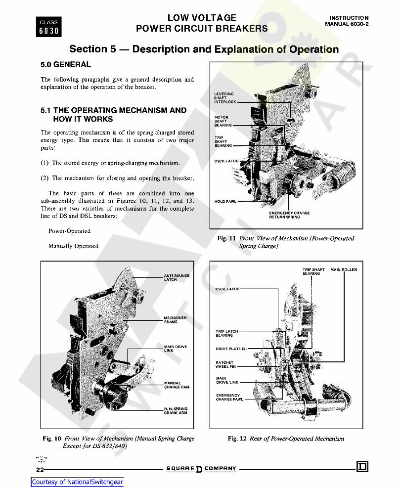
Section 5 — Description and Explanation of Operation5.0 GENERALThe following paragraphs give a general description andexplanation of the operation of the breaker.
5.1 THE OPERATING MECHANISM ANDHOW IT WORKS
The operating mechanism is of the spring charged storedenergy type. This means that it consists of two majorparts:
(1) The stored energy or spring-charging mechanism.
(2) The mechanism for closing and opening the breaker.
The basic parts of these are combined into onesub-assembly illustrated in Figures 10, 11, 12, and 13.There are two varieties of mechanisms for the completeline of DS and DSL breakers:
Power-OperatedFig. 11 Front View of Mechanism (Power-Operated
Spring Charge )Manually Operated
Fig. 10 Front View of Mechanism (Manual Spring ChargeExcept for DS-632/S40 )
Fig. 12 Rear of Power-Operated Mechanism
I Nu a mSQUARE COMPANY22

INSTRUCTIONMANUAL 6030-2 LOW VOLTAGE
POWER CIRCUIT BREAKERSCLASS
6 0 3 0
Referring to Figure 15, the basic elements are mountedon the crank shaft (8). This is a straight shaft with fourflats machined on it, and a crank arm (11) attached toeach end. Each crank arm connects to its closing spring(9) by a formed spring end (10) Figure 16b. The rear ofthe springs anchor to the rear of the mechanism frame.The crank arms (11), motor cutoff switch cam (7), closecam (6) and two drive plates (25) have matching flats; andare thus anchored to the crank shaft. The spring chargeindicator (12) ratchet wheel (17), oscillator (30), andemergency charge device (26) do not have internal flatsbut are mounted on separate bushings and are free torotate on the crank shaft.
Figure 17 is an exploded view of the crankshaft parts.
Figure 16a is a view looking into the right end of thecrankshaft, and shows the position of the componentswhen the springs are charged.
Fig. 13 Rear View of Mechanism (Left Close SpringRemoved)
Figure 16b is a partial view with the springs discharged.
The motor crank shaft assembly (29), carrying a rollerfor driving the oscillator, is pivoted in the right handmechanism side frame. The hold pawl (18) is mounted bymeans of a pin on the mechanism side frame as shown.
5.1.1 Power-Operated Mechanism
In the power-operated version, the mechanism is equippedwith a universal-type motor for automatic charging of theclosing springs. It is equipped with a spring release devicefor electrically closing through a control switch push-button, or other circuit-making device. A shunt trip deviceis supplied for remote tripping through a control switch,relay, etc. In the absence of control voltage, or wheneverdesirable, the closing spring can be charged by hand withthe emergency charging handle. Hand closing of thebreaker can be done by means of the close bar. Handopening of the breaker can be done by means of the tripplate.
In operation, rotation of the motor crank pushes theoscillator arm counterclockwise to make the oscillatorpawl (28) push a tooth in the ratchet wheel (17) androtate the ratchet wheel slightly more than one tooth inthe counterclockwise direction. The holding pawl snapsbehind the corresponding ’advanced tooth, and holds itagainst the torque of the closing springs while theoscillator arm rotates back clockwise to catch anotherratchet tooth. Thus the ratchet wheel is rotated counter-clockwise until the ratchet wheel pin (21) engages the twodrive plates (25) which in turn rotate the crank shaft andthe crank arms in the same direction until the arms areslightly past horizontal dead center. Since the close cam(6) is rigidly mounted on the crank shaft, the same as thedrive plates, it has rotated the same amount as the plates.The close cam carries a stop roller as shown in Figure 22b.Just after horizontal dead center of the crank arms isreached, the torque of the closing springs starts to rotatethe crank, independently of the driving motor. However,the stop roller on the close cam quickly stops themovement of the crank at only a few degrees over centerand holds it there by coming against the spring releaselatch. This is the “spring charged” position. The motorcut-off switch cam (7) operates the switch (15) through alever (13) at this time, and the motor stops.
5.1.2 Explanation of Spring-Charging Mechanismfor Power-Operated Breakers
Figure 14 is an isometric diagram of the principal parts ofa completely power-operated mechanism.
Figure 15 is a front view drawing showing the principalparts of the spring-charging portion of this mechanism.Other parts are omitted for clarity. Figures 16a and 16bshow in greater detail the major parts of the spring-charging mechanism in the two basic positions:
Closing springs charged (16a).
Closing springs discharged (16b).t o
IMa*m SQUARE COMPRNY 23

LOW VOLTAGEPOWER CIRCUIT BREAKERS
INSTRUCTIONMANUAL 6030-2CLASS
6 0 3 0
At the instant that the springs snap over dead center,the lobes of the drive plates raise the pawl lifters (27), andprevent the oscillator pawl (28) from engaging the nexttooth in the ratchet wheel. Thus the oscillator is free andrenders the exact stopping point of the motor not critical.
Power-operated breakers are also equipped for emer-gency hand charging the closing springs. Refer to Fig-ure 18. This operation is similar to that of the motor andoscillator except a separate emergency charge pawl (33) isused to advance the ratchet wheel (17) several teeth oneach stroke of the charge handle (34). This device (26)also pivots on the crank shaft.When the spring release latch is moved below the level
of the stop roller, as later described, the close cam is freeto rotate; and the two closing springs rotate the crank-shaft counterclockwise to close the breaker contacts.They assume the position shown in Figure 16b and thecam as in 22c. During rotation, the drive plates moveaway from the ratchet wheel pin. The ratchet wheel doesnot rotate during the closing operation thus preventingexcessive wear on the teeth and pawls.
5.1.2.1 Power Operation
The electrical operation of the spring-charging motorcircuit is as follows:
The standard basic schematic and connection diagramsare shown in Figure 19a and b. Device Y is the anti-pumprelay.
Fig, 14 Arrangement of the Principal Parts of a Power Operated Mechanism. The Close Spring is Shown in theCharged Position
u nSQUARE COMPANY24

INSTRUCTIONMANUAL 6030-2 LOW VOLTAGE
POWER CIRCUIT BREAKERSCLASS
6 0 3 0
QA}
%i0 Ir\I
0I
mi 00
0 0ONI
ub0000
W0 01=3 CS1 X 10 x a 0Z Xz xzX4b % •sz XI \\inzx54b
09N
© AWWW\ /
1puT X% I %%0 I XX - \2 I X %/ Ai X0 X i i/, HmtJ 0% X
*i—r!
It — - -
© © © © 0 @1. Shutter2. Levering Device Indicator3. Levering Mechanism4. Trip Plate5. Trip Shaft6. Close Cam7. Motor Cut'Of f Switch Cam8. Crank Shaft9. Closing Spring
11. Crank Arm
12. Spring Charge Indicator13. Motor Cut-Off Switch Lever14. Draw Out Unit Base15. Motor Cut-Off Switch16. Ratchet Bushing17. Ratchet Wheel18. Hold Pawl19. Oscillator Bushing22. Spacers (3)23. Stop Bracket
24. Thrust Bearing and Races25. Drive Plates (2)26. Emergency Charge Device27. Pawl Lifter28. Oscillator Paw!30. Oscillator31. Mechanism Side Frame,Right Hand32. Mechanism Side Frame, Left Hand
Fig. 15 Front View Showing Major Parts of the Crank Shaft Assembly. Some Parts are Omitted for Clarity
ov ft.*
SQUARE COMPANY 25

LOW VOLTAGEPOWER CIRCUIT BREAKERS
INSTRUCTIONMANUAL 6030-2CLASS
6 0 3 0
Fig. 16 Power-Operated Spring-Charge Details
SQUARE COMPANY26

INSTRUCTIONMANUAL 6030-2 LOW VOLTAGE
POWER CIRCUIT BREAKERSCLASS
6 0 3 0
Fig. 17 Crank Shaft Assembly of Power-Operated Mechanism
Fig.18 Emergency Spring-Charge on Power Operated Mechanism
I NUs.*-
S Q U A R E n C O M P A N Y 27

LOW VOLTAGEPOWER CIRCUIT BREAKERS
INSTRUCTIONMANUAL 6030-2CLASS
6 0 3 0
Fig. 19 Standard Schematic and Connection Diagrams for Power-Operated Breakersand Trip, Spring Release, Spring Charging Details
SQUARE COMPANY28

INSTRUCTIONMANUAL 6030-2 LOW VOLTAGE
POWER CIRCUIT BREAKERSCLASS
6 0 3 0
Springs are released to close the breaker. When thebreaker closes, the “b” contact opens to cut off springrelease coil and motor, and limit switch (LS) contactsreset.
With the breaker open and springs discharged, themotor is energized through the limit switch (LS) and the“b” contact. The green indicating lamp (G) is controlledby a separate “b” contact, and when lit indicates that thebreaker is open.
If the close contact (CS-C) is maintained, the “Y” relaywill be picked up by the current through the SR coil, andwill open its “Y” contact in the SR circuit. This allowsonly one close operation until the close contact (CS-C)has been reset. The “Y” coil has a very low drop-outvoltage.
Motor runs and charges the closing springs.
When the springs are fully charged, limit switch (LS)opens in the motor circuit and closes in the spring releasecoil (SR) circuit.
When the close contact (CS-C) makes, the springrelease coil (SR) is energized through the normally closed“Y” contact, the limit switch (LS), and breaker “b”contacts. This releases the latch holding the stop roller onthe close cam.
On some circuit breakers a special closing circuit maybe provided which permits the closing springs to beautomatically recharged immediately after the breaker isclosed instead of only after the breaker is opened. This isaccomplished by separating the motor and limit switch
Fig. 20 Principal Parts in a Manually Charged Spring Operated Mechanism.
D SQUARE COMPANY 29

LOW VOLTAGEPOWER CIRCUIT BREAKERS
INSTRUCTIONMANUAL 6030-2CLASS
6 0 3 0
from the “b” contact so the motor operation is independ-ent of the position of the breaker contacts. This arrange-ment makes the breaker suitable for use with instantane-ous reclosing relays or in special operating sequences.
spring holds the front crank assembly in a clockwisedirection against a stop, so that the manual spring-chargehandle socket is normally upright in the unused position.
The standard control utilizes AC or DC control power.For 240 or 120 volt AC equipment, the control powermay be taken direct from the source through fuses. For480 and 600 volt operation, a suitable control powertransformer is used. The transformer is optional for 240volt systems. DC control voltages are 48, 125 or 250.
1. Manual Charge Handle2. Manual Charge Handle Socket3. Front Crank Assembly4. Pivot Pin5. Mounting Bracket6. Rear Crank Assembly7. Crank Pin8. Manual Charge Cams (3)9. Crank Shaft
10. Claw Stop
:
CDWhen the breaker closed, the “a” contact in the shunt
trip (SH-TR) coil circuit also closed to complete this tripcircuit. The red indicating lamp (R) supervises the shunttrip circuit to show that it is in working order, andindicates that the breaker is closed.
©©1'-J 0©When control power is turned on, any power-operated
breaker in the test or connected position with its springsdischarged will have its motor energized until the closingsprings are charged.
i—/
© /
©©5.1.3 Manual-Operated Mechanisms
© ©'K~brzr7Z25~k\On manually operated breakers, the closing spring can be
charged only by hand, as described in Section 4.2. Asusually equipped, the breaker can be closed only by hand,with the close bar. As an optional extra, a dosing springrelease device can be supplied on these breakers.
Fig. 21 Spring-Charging Mechanism on ManualOperated BreakersHand opening of the breaker can be done only by
means of the trip plate ; however a shunt trip device can besupplied as an optional extra. The manual charge cam is mounted on the crank shaft
so that the crank pin hooks behind the hook-shapedsurface of the manual charge cam as shown, when thehandle is upright and the springs discharged. The springsare fully charged by a 90 degree counterclockwiserotation of the handle. The crank spring then returns theassembly to the handle-upright position. In operation thismeans a single downward stroke from vertical to approxi-mately the horizontal position. As the “Spring charged”position is reached, the handle becomes effortless to turnand the closing spring crank arms snap over center.
5.1.4 Explanation of Spring-Charging Mechanismfor Manually Operated Breakers
Figure 20 is another isometric diagram to illustrate themechanism in a manually operated breaker. For sake ofclarity, the actuator has been omitted.
Figure 21 gives the details of this spring-charging devicewhich is located between the mechanism right hand sideframe and the right crank arm. A part of this assembly isthe manual charge cam which is rigidly fixed to the crankshaft, the same as the main close cam and crank arms.
It is possible to manually recharge the closing springsimmediately after closing the breaker and before it hasbeen tripped open. This results in the springs loading theassociated bearings and latches for long periods. Also anextra close operation, or trip-free operation, will benecessary on levering the breaker to the disconnect andremove positions. Therefore, it is recommended that thesprings be charged just prior to the closing of the breaker.
The other parts are the front crank assembly which ispivoted to a bracket fastened to the main frame base, andhas a socket for the manual charge handle. The rear crankis pivoted to the front portion and has a cross-wise pin onthe end. A spring forces this pin against the cam. Another
U & * nSQUARE COMPANY30

INSTRUCTIONMANUAL 6030-2 LOW VOLTAGE
POWER CIRCUIT BREAKERSCLASS
6 0 3 0
Fig. 22 These Sketches Show the Four Basic Positions of Breaker and Linkage with Enlarged View of Trip Shaftand Latch
U * *
S Q U A R E n C O M P A N Y 31

LOW VOLTAGEPOWER CIRCUIT BREAKERS
INSTRUCTIONMANUAL 6030-2CLASS
6 0 3 0
5.1.5 Circuit Breaker Closing Mechanism The angular position of the close cam in Figure 22acorresponds to the angular position of the drive plates andclosing spring crank arms shown in Figure 16b. The triplatch is in the tripped position and it will reset to thelatched position at the end of the spring charging stroke.The closing springs are charged by counterclockwiserotation of the ratchet and drive plates until the close camstop roller meets the spring release latch, as shown inFigure 22b.
This mechanism is of the general variety of mechanicallytrip-free mechanisms. This means that the breaker can beopened or tripped free from the closing mechanism at anypoint in its closing stroke. It also means that if the triplatch is held in the “trip” position while the spring releaselatch is released, the closing springs will make a trip-freeoperation but the breaker contacts will not close or moveappreciably toward the closed position.
Note in Figure 22b also that the lower end of the maindrive link, with the main roller, has swung upward andtoward the left, pushing the trip latch constraining link soas to rotate the trip latch back to the reset position. Thisoccurs at the same time that the spring charge is completeand just before the close cam stop roller strikes the springrelease latch. The position of the cam in Figure 22bcorresponds to the position of the drive plates in Figure16a spring charged, breaker open.
Based on this construction, the breaker close and triplinkage can have four steady state conditions. Thearrangements of the basic close and trip linkage for thesefour conditions are shown in Figures 22a, 22b, 22c, and22d as follows:
Figure 22a Breaker Open, Springs Discharged, Trip LatchNot Reset.Figure 22b Breaker Open, Springs Charged, Trip LatchReset. The breaker is now ready to be closed. Closing is
started by counterclockwise rotation of the spring releaselatch. Refer again to Figure 22b. This removes the hold onthe close cam stop roller, and allows the force of theclosing springs to rotate the close cam counterclockwise
Figure 22c Breaker Closed, Springs Discharged.Figure 22d Breaker Closed, Springs Charged.
Fig. 23 Shunt Trip Details Showing Trip Shaft Adjustment
* '*'*,>
DS Q U A R E n C O M P A N Y32

INSTRUCTIONMANUAL 6030-2 LOW VOLTAGE
POWER CIRCUIT BREAKERSCLASS
6 0 3 0
and close the breaker. The linkage is then in the positionshown in Figure 22c. The close cam has rotated about 180degrees.
lever downward through the main drive link to the mainroller. The main drive link at the main roller is connectedto the trip latch by the roller constraining link. Thedownward force on the main drive link results in a pullingforce on the roller constraining link. This force tends torotate the trip latch counterclockwise, but the trip latch iskept from rotating by overlap of the latch surface of thetrip shaft. A very small rotation of the trip shaft thusreleases the trip latch to rotate counterclockwise to theposition shown in Figure 22a. The enlarged views of thetrip shaft and trip latch tip in Figure 22e show in detailthe rotation of the trip shaft for release of the trip latch.Thus the entire linkage collapses under the force of themain contacts and comes to rest with the breaker open, asin Figure 22a. Note that the trip latch is still in thereleased position, i.e., not reset.
The spring release latch can be rotated by twomethods:
1. By the spring release device on power-operatedbreakers, as shown in Figures 14 and 31b.
2. By the close bar, through the linkage shown inFigure 31b.5.1.6 Circuit Breaker Tripping or Opening
MechanismReferring to Figure 22c showing the breaker in the closedposition, the breaker is tripped open by counterclockwiserotation of the trip shaft. The trip shaft extends across theleft hand part of the breaker, from the left handmechanism side sheet to the left hand breaker side sheet;and can be rotated by several devices as later described.
If the breaker stands open with springs charged as inFigure 22b, and if the trip shaft is held in the rotated ortrip position, an attempt to close will result in a trip-freeoperation. This is so because, with the trip shaft in thetrip position, there is no restraint on the trip latch, so noforce is applied to the main link to close the breaker.Rotation of the trip shaft accomplishes breaker open-
ing as follows: Staying with Figure 22c, the main contacts(not shown) produce a clockwise twisting force or torqueon the pole shaft. This is transmitted by the center pole
Although certain interlocking operations may or willresult in this trip-free type of operation, it causes some
Fig. 24 Actuator
IX ft . *-m 5Q U H R E D C O M P A N Y 33
LOW VOLTAGEPOWER CIRCUIT BREAKERS
INSTRUCTIONMANUAL 6030-2CLASS
6 0 3 0
extra shock on the mechanism parts. Therefore trip-freeoperations should be avoided.
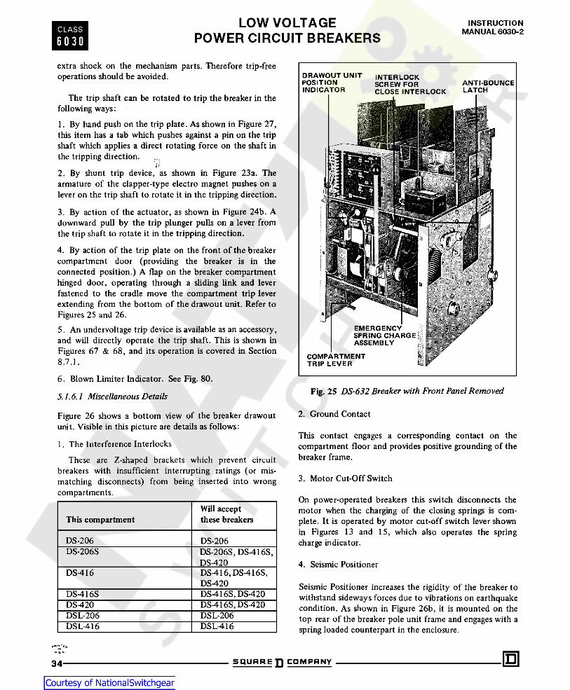
The trip shaft can be rotated to trip the breaker in thefollowing ways:
1. By hand push on the trip plate. As shown in Figure 27,this item has a tab which pushes against a pin on the tripshaft which applies a direct rotating force on the shaft inthe tripping direction.
V2. By shunt trip device, as shown in Figure 23a. Thearmature of the clapper-type electro magnet pushes on alever on the trip shaft to rotate it in the tripping direction.
3. By action of the actuator, as shown in Figure 24b. Adownward pull by the trip plunger pulls on a lever fromthe trip shaft to rotate it in the tripping direction.4. By action of the trip plate on the front of the breakercompartment door (providing the breaker is in theconnected position.) A flap on the breaker compartmenthinged door, operating through a sliding link and leverfastened to the cradle move the compartment trip leverextending from the bottom of the drawout unit. Refer toFigures 25 and 26.5. An undervoltage trip device is available as an accessory,and will directly operate the trip shaft. This is shown inFigures 67 & 68, and its operation is covered in Section8.7.1.
6. Blown Limiter Indicator. See Fig. 80.Fig. 25 DS-632 Breaker with Front Panel Removed5.1.6.1 Miscellaneous Details
2. Ground ContactFigure 26 shows a bottom view of the breaker drawoutunit. Visible in this picture are details as follows:
1. The Interference Interlocks
These are Z-shaped brackets which prevent circuitbreakers with insufficient interrupting ratings (or mis-matching disconnects) from being inserted into wrongcompartments.
This contact engages a corresponding contact on thecompartment floor and provides positive grounding of thebreaker frame.
3. Motor Cut-Off Switch
On power-operated breakers this switch disconnects themotor when the charging of the closing springs is com-plete. It is operated by motor cut-off switch lever shownin Figures 13 and 15, which also operates the springcharge indicator.
Will acceptthese breakersThis compartment
DS-206 DS-206DS-206S DS-206S, DS-416S,
DS-420 4. Seismic PositionerDS-416 DS-416, DS-416S,
DS-420 Seismic Positioner increases the rigidity of the breaker towithstand sideways forces due to vibrations on earthquakecondition. As shown in Figure 26b, it is mounted on thetop rear of the breaker pole unit frame and engages with aspring loaded counterpart in the enclosure.
DS-416S, DS-420DS-416SDS-420 DS-416S, DS-420
DSL-206DSL-206DSL-416 DSL-416
I N<J B. mS Q U A R E D C O M P A N Y34

INSTRUCTIONMANUAL 6030-2 LOW VOLTAGE
POWER CIRCUIT BREAKERSCLASS
6 0 3 0
Fig. 26aBottom View of Breaker Unit Showing InterferenceInterlock, Motor Cut-off Switch and Other Detailsnot Visible from Above
Fig. 26c Front View Showing Close Bar Guard
Fig. 26b Rear View Showing the Seismic Positioner
#*7Nrto
SQUARE COMPANY 35

LOW VOLTAGEPOWER CIRCUIT BREAKERS
INSTRUCTIONMANUAL 6030-2CLASS
6 0 3 0
5. Close Bar GuardW A R N I N G
This covers the close bar to prevent unintentional manualclosing of the breaker. It is mounted on the front panel tocover the close bar. In case of emergency, the breaker maybe closed by pushing the close bar through a small hole inthe cover. See Figure 26c.
DO NOT TAMPER WITH INTERLOCKING, ANDIF IS NOT FUNCTIONING, HAVE IT COR-RECTED. INTERLOCKING THAT IS FUNC-TIONING IMPROPERLY CAN RESULT IN ME-CHANICAL AND ELECTRICAL DAMAGE TOEQUIPMENT AND BODILY INJURY TO PER-SONNEL.6. Operation Counter
Mechanical counter mounted under the top plate belowthe auxiliary switch provides the record of the number ofbreaker operations. The counter is connected throughlinkage to the pole shaft .
a. The REMOVE position.b. The DISCONNECT position.c. The TEST position.d. The CONNECT position.
In addition there is an interference interlock describedin Section 5.1.6.1.
This mechanical interlock system serves basic purposesas follows:
5.1.7 Mechanical Interlocking, Description andExplanation of Operation
To increase safety to personnel and the circuits to whichthe breaker is connected, the complete unit is equippedwith automatic mechanical interlocking. This interlockingis effective in various ways in the four breaker positions(Figure 27):
1. In the REMOVE position it prevents the breaker frombeing closed and prevents the closing springs from being
0 O00 0 Q 0P
_:.^i nrr i n/TUA-/A-/71 . CONNh- — -H 1 I I
+ t —TEST—-CUSC-REMOVE
70 I
0
0 v \V I
\
XN
5. Indicator Pivot Pin6. Traveling Stop Nut7. Traveling Stop Nut
Clamp
1. Indicator Index Tab2. Front Panel3. Levering Worm Shaft4. Levering Worm
8. Indicator Lever9. Levering Worm Gear
10. Levering Shaft
Fig. 27 Drawout Unit Position Indicator*. * oSQUARE COMPANY36

INSTRUCTIONMANUAL 6030-2 LOW VOLTAGE
POWER CIRCUIT BREAKERSCLASS
6 0 3 0
charged or remaining charged. The levering device shutteris held open.
5.L7.2 The DISCONNECT Position
In this position the breaker has moved only a fraction ofan inch into its compartment and will be shown by theposition indicator.
2. In the DISCONNECT position it prevents the breakerfrom being withdrawn from its compartment.
3. In the TEST position it permits all normal no-loadoperations of the breaker with the primary disconnectcontacts separated.
In this position the following conditions exist:
A. The breaker will be held in its compartment as thelevering rollers have lowered into the slots in the cradlearms.4. In the CONNECT position it prevents the disconnect-
ing or withdrawal of a closed breaker. This prevents thedrawing of dangerous, destructive arcs on the disconnect-ing contacts if the circuit is loaded.
B. The shutter will close over the levering device hexshaft.
5. While moving the breaker in either direction betweenthe TEST position and the CONNECT position or theDISCONNECT position ; or while standing in any interme-diate position, it prevents the closing of the breaker.Therefore it prevents the connecting of the closed breakerto the power circuits. This prevents arcing on thedisconnecting contacts as would occur in going intocontact with a load on the circuit.
C. The shutter may be locked closed and the breakerheld trip-free by a padlock as described in Section5.1.8.5, thus locking it in the compartment.
D. Both primary and secondary disconnecting contactsare separated.
E. The breaker is open.Here are the detailed interlocking conditions which
exist in each of the four breaker positions:5.1.7.3 The TEST Position
This is the position of the breaker when at a point inbetween the DISCONNECT position and the CONNECTposition, as shown by the draw-out position indicator. Inthis position the main disconnecting contacts are sepa-rated enough to permit safe operation of the breaker.However, the secondary contacts are made up.
5.1.7.1 The REMOVE Position
This is the position of the breaker when nearest the frontof its compartment, and is where the breaker must beplaced when it is installed after having been completelyoutside of the compartment. It is the farthest point in thecompartment to which the breaker can be withdrawn andstill permit the compartment door to be reclosed. In this position the following conditions exist:
A. The breaker must arrive in this position-from eitherdirection with its contacts open. Its closing springs maybe either charged or discharged when coming from theconnected position.
In this position, the following conditions exist:
A. The breaker is open.-
B. The closing springs are discharged. If an attempt ismade to charge the springs, a trip-free operation willresult.
B. When the levering crank handle is removed, it ispossible to close and trip the breaker by hand orelectrically.
C. The breaker cannot be closed either electrically orby hand. C. Just before the breaker arrives in the TEST position
from the DISCONNECT position, the secondary con-tacts make up and the spring-charge motor automat-ically runs and charges the closing springs on power-operated breakers.
D. The breaker can be withdrawn from the compart-ment by direct pull. (The levering device is not engagedwith the cradle.)
E. The levering device arms are in a horizontal positionwith their rollers pointing toward the rear. See Fig-ure 2.
D. The breaker can be closed by hand, or electrically,after the springs are charged as in paragraph C above.
•«’** *©u i*IQ SQUARE COMPANY 37

LOW VOLTAGEPOWER CIRCUIT BREAKERS
INSTRUCTIONMANUAL 6030-2CLASS
6 0 3 0
E. The breaker can be tripped open by hand, orelectrically through the shunt trip device.F. The trip plate on the hinged compartment door willnot trip the breaker.G. The breaker must be open before further leveringcan be done.
H. The overload tripping characteristics can be visuallychecked or changed. Amptector trip devices can beelectrically checked ari/i calibrated with a portable testkit. (Accessory equipment)
5.1.7.4 The CONNECT Position
This is the position in which both primary and secondarydisconnecting contacts on the breaker are engaged withtheir stationary counterparts in the compartment.
It is the farthest position from the front of thecompartment into which the breaker can be levered, as(1) shown by the drawout position indicator, and(2) when the mechanical stop is felt as a sudden increasein load on the levering crank handle.
NOTE
the levering device, or while it is standing in anyintermediate position between “TEST” and “CONNECT”or “DISCONNECT”, is shown in Figure 28a and b. Figure28a shows the shutter and trip plate for normal operation,such as in DISCONNECT, TEST, or CONNECT positions.The breaker can be closed and tripped open by allavailable devices in the latter two positions except the tripplate on the hinged compartment door.
In Figure 28a, the shutter prevents pushing the leveringdevice crank handle onto the worm shaft. If the shutteralone is pushed downward, it will rotate slightly about itspivot pin and its lower projection (See Figure 28a) strikesthe hook on the trip plate, and the worm shaft will not becleared. So it is necessary to push the trip plate in, whichmoves the hook back out of the way of the shutter lowerprojection. This permits the shutter to be pushed down-ward to clear the worm shaft for the levering device crankhandle, as shown in Figure 28b.
Note that pushing the trip plate in also pushes the tripshaft pin so as to rotate the trip shaft counterclockwise,thus tripping the breaker open. If closing is attemptedwith the linkage as in Figure 28b, a trip free operation willbe made.
When levering in from the TEST position, an increase inload on the crank handle will be felt as the main discon-necting contacts are engaged. As cranking is continued,the load will decrease some and then suddenly increase asthe final connected position stop is reached.
In this position all of the conditions listed for TESTposition also exist, except
Movement of the shutter also is controlled by theinterlock cam, mounted on the levering device shaft to theleft of the worm gear. The interlock cam has a fixedrelation to the levering device arms. Figure 29a, b, c, andd show the relation between the shutter , interlock camand levering device arms for the four basic positions of thedrawout unit in the compartment.
IN THIS POSITION, DO NOT ATTEMPT TOELECTRICALLY CHECK THE AMPTECTORTRIP DEVICE WITH THE TEST KIT OR BYANOTHER METHOD BECAUSE BREAKERWILL BE TRIPPED AND CAUSE DISRUPTIONOF SERVICE.
Figure 29a shows the CONNECT position. The cam isin a position to allow free travel of the shutter interlockpin.
Therefore the shutter can be pushed downward, butonly after pushing in the trip plate as in Figure 28. Thistrips the breaker and therefore prevents levering out withthe breaker closed.
The trip plate on the hinged compartment door will beoperative, and can be used to trip the breaker when thisdoor is closed.
Figure 29b shows the TEST position. Note thatbetween CONNECT and TEST positions the cam willrotate so as to block the shutter interlock pin. Thisprevents the shutter returning to its closed position andreleasing the trip plate if the levering device crank handleis removed. Thus, if a closing operation is tried during thispart of the travel, a trip-free operation occurs and thebreaker contacts do not close. Note that this is true foreither direction of breaker travel so that no load is madeor broken at the disconnecting contacts.
In addition to the above interlocks, the interferenceinterlock described in Section 5.1.6.1 prevents a breakerof the wrong frame size from being placed in a compart-ment.
5.1.8 Detailed Explanation of MechanicalInterlock System
That part of the interlock system which prevents closingof the breaker while being driven in either direction by
u » ^ nSQUARE COMPANY38

INSTRUCTIONMANUAL 6030-2 LOW VOLTAGE
POWER CIRCUIT BREAKERSCLASS
6 0 3 0
When the breaker gets to the TEST position, a slot inthe interlock cam allows free movement of the shutterinterlock pin, and the shutter returns to closed positionwhen the crank is removed. The levering device arms arealmost vertically downward.
Figure 29c shows the DISCONNECT position. Herealso the cam rotates so as to block the shutter interlockpin while the breaker is between positions thus holdingthe shutter open. When the exact position, as shown onthe indicator, is reached, the shutter will close when the
Fig. 28 Relation of Shutter; Trip Plate, and Trip Shaft
I Nu a *-n SQUARE ]] COMPANY 39

LOW VOLTAGEPOWER CIRCUIT BREAKERS
INSTRUCTIONMANUAL 6030-2CLASS
6 0 3 0
crank is removed. The levering arms will be approximately40° below the horizontal.
TEST position. This causes a trip-free operation of theclosing mechanism because it occurs while the leveringdevice crank handle is necessarily still on the worm shaft,and the closing springs are charged if the breaker iselectrically operated. This is because the crank handle isstill being used to move the breaker in the final part of itstravel to the DISCONNECT position. Thus, the trip plateis still pushed in and consequently the breaker is trip free.
Figure 29d shows the REMOVE position. Here theinterlock cam stops with the shutter interlock pinblocked. Thus the shutter stays down and the breakerstays tripped when the crank handle is removed. Thebreaker is held trip-free, so it cannot be closed. Also, byanother interlock described later, the close-release latchcannot be released. 2. Figure 30a, b, c and d shows the essential parts of the
spring discharge interlock, a and b show the leveringdevice in the REMOVE position. The Interlock Plate hastwo horizontal pins 7 and 8 extending from it, as shownin a, b, c and d. The upper one is designated arbitrarily asPin A and is darkened to distinguish it from Pin B. In
5.1.8.1 Spring Discharge Interlock
1. The purpose of this interlock is to operate theclose-release latch as the breaker is moved out beyond
Fig. 29 Relation of Shutter, Interlock Cam and Levering Device Arms
A DSQUARE COMPANY40

INSTRUCTIONMANUAL 6030-2 LOW VOLTAGE
POWER CIRCUIT BREAKERSCLASS
6 0 3 0counterclockwise by Pin B, to the CLOSE position. Thisreleases the spring release latch through the linkage shownin Figure 30, which results in a trip-free operation of thebreaker if the closing springs are charged. This happens
levering the breaker out to the REMOVE position asshown in a and b the levering shaft has turned counter-clockwise until the levering device arms are horizontal tothe rear. As it rotates, the close bar cam has been rotated
Fig. 30 Gose-Release Interlock to Discharge Springs on Levering Out of Compartment and Conn. Positionno Manual Gose Interlock
»»»n S Q U A R E D C O M P R N Y 4 1

LOW VOLTAGEPOWER CIRCUIT BREAKERS
INSTRUCTIONMANUAL 6030-2CLASS
6 0 3 0
interlock plate can be rotated freely on the shaft about 10degrees. This is because the “wide” slot is considerablywider than the drive pin. If the interlock screw is in placein the “narrow” slot, the Interlock Plate has practically noplay and is forced to rotate exactly as much as thelevering device shaft rotates.
because the levering device crank has the Trip plate heldin the Trip Position. If the breaker is manually operated,levering out can be stopped at the TEST position. Removethe levering device crank handle and (1) Close the breakerand (2) Trip the breaker. This will discharge the springs sothat, when the REMOVE position is reached, there willnot be a trip free operation. The Close bar will merely be{hilled into the “CLOSE” position. Figure 30c shows the standard arrangement, without
the interlock screw, with the levering device arms in theCONNECT position. Note that there is a clearancebetween the back of the hook and Pin A. This permits theclose bar to be pushed to the “close” position and closethe breaker.
5.L8.2 Connected Breaker Manual Gose Interlock
The purpose of this Interlock is to make possible a choicebetween being able to close the breaker by hand-push onthe Gose bar and not being able to, with the breaker inthe CONNECT position. Some consider it undesirable todo so. Referring to Figure 30a, the Interlock PlateAssembly is keyed loosely to the levering device shaft by adrive pin as shown. If the interlock screw is omitted, the
In Figure 30d, all parts are in the same position as inFigure 30c, except that the interlock screw has beenplaced in the “narrow slot”. This arrangement is shown inFigure 25. This forces the interlock plate to rotate about
Fig. 31 Close Interlock to Prevent Efforts to Gose a Breaker that is Already Closed
ro-’tou a ». nSQUARE COMPANY42

INSTRUCTIONMANUAL 6030-2 LOW VOLTAGE
POWER CIRCUIT BREAKERSCLASS
6 0 3 0
10 degrees further than in Figure 30c, so that there isalmost no clearance between Pin A and the back of thehook. Consequently the Close bar cannot be pushed tothe “Close” position. However, the breaker can beremote-closed by applying control voltage to the springrelease coil through a control switch or other circuit-making device.
® © ©
f= -
©5.1.8.3 Breaker Equipped for Electric Lockout ©
/ f f© oPower operated breakers may be equipped for electriclockout, meaning that closing an unenergized circuit isprevented. This may be the main circuit or any otherdesired circuit. This is accomplished by making it impos-sible to release the spring release latch by the springrelease device unless the monitored circuit is energized.
The spring release coil (SR) is wired through the contacton the motor cut-off switch that closes as the closingsprings become fully charged. The remainder of the circuitis through a front panel closing pushbutton switch and tothe terminals of the circuit being monitored. Thus, whenthe monitored circuit is energized properly, the breakermay be closed through the panel pushbutton switch,provided in addition that the closing springs are charged.
fT\ ©VCD-- '̂V y
J
©©U il'V'
1. Padlock Plate Notch2. Padlock Plate3. Trip Plate4. Front Panel5. Shutter6. Levering Device Worm Shaft7. Projection on Shutter8. Bent Tab on Padlock Plate9. Projection on Trip Plate
10. Padlock Interlock Lever11. Pin on Padlock Interlock Lever12. Trip Shaft
As an additional safeguard against undesired closingunder this electric lockout condition, all such breakerswill be equipped with the interlock screw as described inSection 5.1 .8.2 above. This prevents hand closing of thebreaker in the CONNECT position.
Manually operated breakers may also be furnished withthis feature if they are equipped with optional electricalspring release devices. Fig. 32 Padlock Device - Locked Trip Free and
Shutter Raised5. L8.4 Closed Breaker Interlock
Figure 31 shows how operation of the spring release latchis prevented when the breaker already is in the closedposition. The Close Bar is connected to the spring releaselatch by a link and bell crank. The link is pivoted on thelower end of the close bar cam by a pin as shown. As theClose Bar is pushed, the pin and latch link will move tothe right, along with the lower end of the cam. The lowerend of the link is facing a knife edge pivot on the verticalarm of the bell crank. The upper end of the link is facingthe Open-Close Indicator Pin. This pin is at the left end ofits slot in the mechanism side frame with the breaker openand at the right end with the breaker closed. As the CloseBar is pushed, the link therefore has two possible endpivots. If the breaker is open the upper end of the linkwill swing to the right until it touches the indicator pin.The lower end of the link will then swing to the right and
push the vertical arm of the bell crank to the right. Thehorizontal arm of the bell crank moves downward andpresses directly on the spring release latch, allowing thebreaker to close.
If the breaker already is closed and the Close Bar ispushed, the upper end of the spring release latch link willswing free to the right because the indicator pin is notthere to stop it. Consequently, no force is applied to thevertical arm of the bell crank, and nothing else happens.
5.1.8.5 Padlocking Provision
Figure 32 shows the essential parts of the padlockinterlock. The breaker is padlocked in the trip-free
•*U * *m SQUARE ]] COMPANY 43

LOW VOLTAGEPOWER CIRCUIT BREAKERS
INSTRUCTIONMANUAL 6030-2CLASS
6 0 3 0
condition in which the breaker cannot be closed and thebreaker cannot be moved with the levering device. Thisfigure shows the relation of parts for padlocking in thetrip-free, shutter up condition. There are three major partsinvolved, which are interleaved and assembled on the lefthand side of the levering device assembly:
normally into a curved notch in the bottom edge of thepadlock plate.
To padlock the breaker, push the trip plate in. Pull thepadlock plate forward. This exposes the padlock slot inthe padlock plate. Insert the padlock and lock.
Movement of the trip plate pushes the front end of thepadlock interlock lever down, moving its pin downwardand out of the notch in the padlock plate. Forwardmovement of the padlock plate and backward movementof the trip plate places the pin in the padlock interlocklever behind the notch in the padlock plate. With thepadlock plate held forward, the padlock interlock levercannot move. The projection from the trip plate isconsequently held in the slot in the padlock interlocklever, so the breaker remains locked in the trip-freecondition until the padlock is removed and the membersare returned to their normal positions by their returnsprings. While so locked, the shutter is prevented fromdownward travel by a horizontal projection striking abent-over tab on the padlock plate.
1. The Shutter
2. The Trip Plate
3. The Padlock Interlock Lever
The Padlock Interlock lever is located between the TripPlate and the Padlock Plate, and is pivoted on a fixedcenter toward the rear of the breaker. The front part ofthis lever has a sloping slot into which a projection fromthe trip plate extends. Horizontal movement of the tripplate by cam action of the projection against the walls ofthe slot, causes the front of the interlock lever to move upor down. The interlock lever is pushed upward by aspring. This lever also has a short pin extending outward
o. ». . mS Q U A R E D C O M P A N Y44
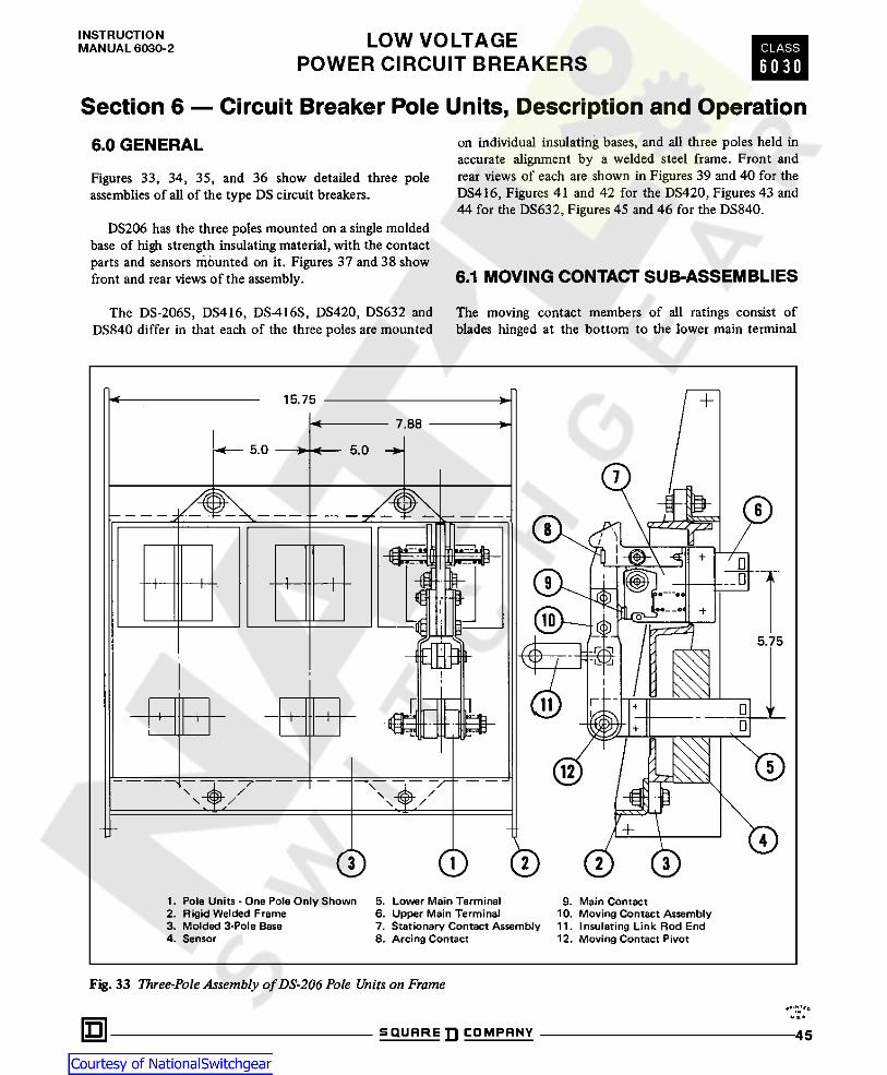
INSTRUCTIONMANUAL 6030-2 LOW VOLTAGE
POWER CIRCUIT BREAKERSCLASS
6 0 3 0
Section 6 — Circuit Breaker Pole Units, Description and Operation6.0 GENERAL on individual insulating bases, and all three poles held in
accurate alignment by a welded steel frame. Front andrear views of each are shown in Figures 39 and 40 for theDS416, Figures 41 and 42 for the DS420, Figures 43 and44 for the DS632, Figures 45 and 46 for the DS840.
Figures 33, 34, 35, and 36 show detailed three poleassemblies of all of the type DS circuit breakers.
DS206 has the three poles mounted on a single moldedbase of high strength insulating material, with the contactparts and sensors mounted on it. Figures 37 and 38 showfront and rear views of the assembly. 6.1 MOVING CONTACT SUB-ASSEMBLIES
The moving contact members of all ratings consist ofblades hinged at the bottom to the lower main terminal
The DS-206S, DS416, DS-416S, DS420, DS632 andDS840 differ in that each of the three poles are mounted
+15.75* >
7.88* *5.0 5.0> *
7i-:§-
8@$- /
\„09
'• *0
•« H-o
i- @5.75
I E ~ 3 H
I 4 Vi.+
12 /
/“\/\ /\/\
© © 2 3
1. Pole Units - One Pole Only Shown2. Rigid Welded Frame3. Molded 3-Pole Base4. Sensor
5. Lower Main Terminal6. Upper Main Terminal7. Stationary Contact Assembly8. Arcing Contact
9. Main Contact10. Moving Contact Assembly11. Insulating Link Rod End12. Moving Contact Pivot
Fig. 33 Three-Pole Assembly ofDS-206 Pole Units on Framei*.u&n SQUARE ]] COMPANY 45

LOW VOLTAGEPOWER CIRCUIT BREAKERS
INSTRUCTIONMANUAL 6030-2CLASS
6 0 3 0through controlled pressure rotating contacts and withmain and arcing contacts at the upper end. The arcingcontacts of all of the five ratings shown are essentially thesame design. The number of blades, the size of the mainterminals and the number of fingers in the main discon-necting contacts vary with the rating. The DS206 has twomoving blades, the DS416 and DS420, four movingblades, and the DS632 and DS840, eight moving blades.On the DS206, two butt type main contacts and a knife
blade arcing contact are located between the two hingedblades. On the DS416 and DS420 the main contactmember, i.e. which makes actual contact with thestationary contacts, is a horizontal member to which allblades are connected. On the DS632 and DS840 there aretwo sets of contacting surfaces, one vertically above theother, for making contact with two corresponding rows ofstationary contact fingers. The arcing contact assembly isbolted to the top of the main moving contact blade
15.75 -* ® ®7.88CL+5.0 5.0*-
fTvUir§^+
7Z.t it ©& (s>!
i;4
i i i> iu. J i kto'V— * v,«: , > s
U.'U£ ? -©
7777i; !
(5)— /5.25/1 )[ { } y
7^ > ,vtJ TZf
* n ' f11 wrrrrf
5 3- 4 I I(S>
i \EZZ- \\' +N /! i i
-© 1' ii
-Jt j © \ \ V
&© DS420 © © DS416 © © ©1. Individual Single Pole Unit2. Rigid Welded Frame3. Molded Pole Base4. Sensor
5. Lower Main Terminal6. Upper Main Terminal7. Stationary Contact Assy.8. Arcing Contact
9. Main Contact10. Moving Contact Assy.11. Insulating Link Rod End12. Moving Contact Pivot
Fig. 34 Three-Pole Assembly of DS-416/420 Pole Unit on Frame
nSQUARE ]] COMPANY46
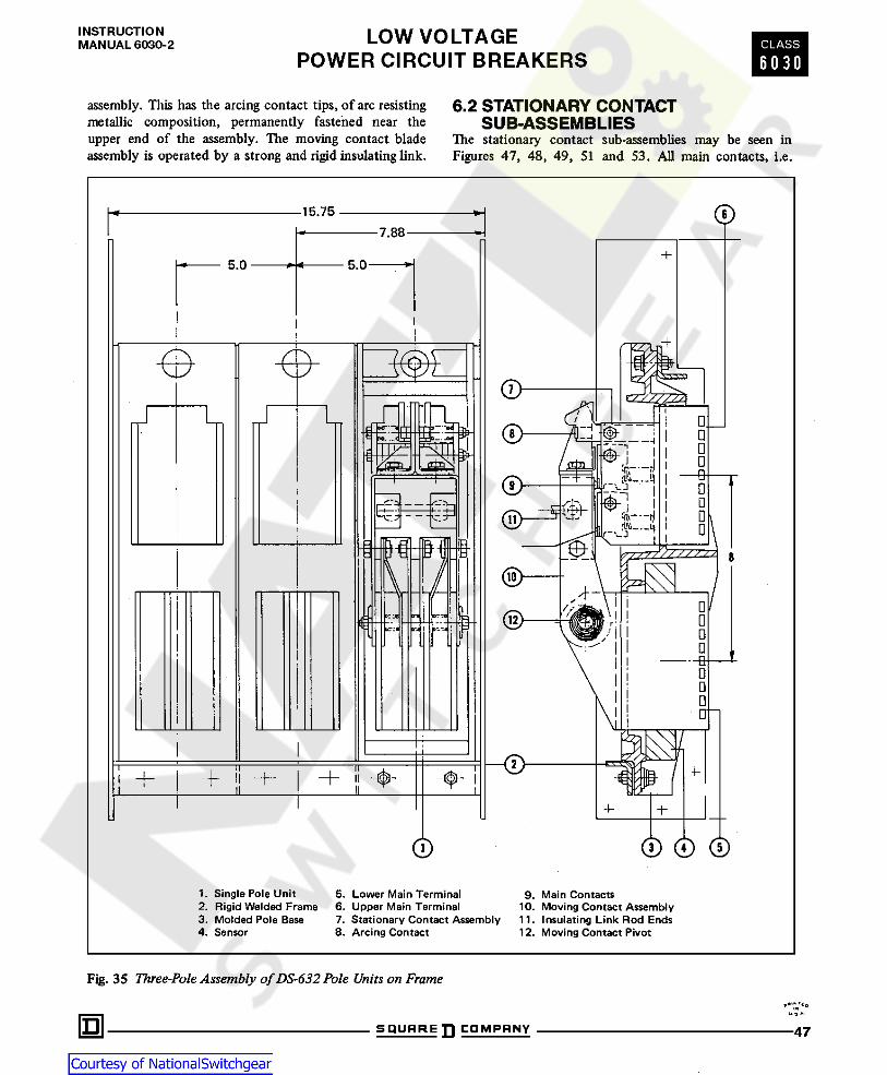
INSTRUCTIONMANUAL 6030-2 LOW VOLTAGE
POWER CIRCUIT BREAKERSCLASS
6 0 3 0
6.2 STATIONARY CONTACTSUB-ASSEMBLIES
assembly. This has the arcing contact tips, of arc resistingmetallic composition, permanently fastened near theupper end of the assembly. The moving contact bladeassembly is operated by a strong and rigid insulating link.
The stationary contact sub-assemblies may be seen inFigures 47, 48, 49, 51 and 53. All main contacts, i.e.
©15.75* *7.88
+5.0 5.0+T*"
I
e0
7\ \ o0i o33H i
l -F iJ
fa— S40 tr -J? 0fa
D0 . i— t} D
i-VJ iI1 I & X / / / £. 8v / / / Z.
0 \-±*Vi/V i0 IHI* anr
ic-:« > --u
D0
1\
-0t i l IIT
i4- -F
0 0 0O1. Single Pole Unit2. Rigid Welded Frame3. Molded Pole Base4. Sensor
5. Lower Main Terminal6. Upper Main Terminal7. Stationary Contact Assembly8. Arcing Contact
9. Main Contacts10. Moving Contact Assembly11. Insulating Link Rod Ends12. Moving Contact Pivot
Fig. 35 Three-Pole Assembly of DS-632 Pole Units on Frame
i* a-m SQUARE COMPANY 47

LOW VOLTAGEPOWER CIRCUIT BREAKERS
INSTRUCTIONMANUAL 6030-2CLASS
6 0 3 0
those which carry the main continuous load current, areof the butt type composed of a multiplicity of fingers.Each finger is hinged at the upper end under controlledpressure. Compression springs at the lower end applypredetermined pressure against the moving main contactin closing, and standing in the closed position. Thesesprings are visible in the photograph of the DS206 only.With this construction, the pressure on the main contactsurfaces is increased during the carrying and opening ofhigh short circuit currents because the magnetic field ofthe current pushes the lower end of the finger toward the
moving contact. Hinging the finger at the top thus resultsin what is sometimes called “blow-on” action. This greatlyincreases the capability of the entire contact assembly towithstand the high fault currents associated with thesebreaker ratings.
The stationary arcing contacts are similar for all ratingsand consist of two parallel fingers, one on each side of thestationary terminal member. They are pushed toward eachother by compression springs and have arc resisting tips.
2713.5
©8 8
o
©o
mi 4»iii
(!) 30
&D
© Qa©
© 8
© ao&
J_0
O © ©
7. Stationary Contact Assembly8. Arcing Contact9. Main Contacts
10. Moving Contact Assembly11. Insulating Link Rod Ends12. Moving Contact Pivot
1. Single Pole Unit2. Rigid Welded Frame3. Molded Pole Base4. Sensor5. Lower Main Terminal6. Upper Main Terminal
Fig. 36 Three Pole Assembly of DS-840 Pole Units on Frame
INu DSQUARE COMPANY48

INSTRUCTIONMANUAL 6030-2 LOW VOLTAGE
POWER CIRCUIT BREAKERSCLASS
6 0 3 0
The moving arcing contact thus wedges the stationarycontact fingers apart as the breaker closes.
Figures 37 thru 46 show the combined moving andstationary contact sub-assemblies of the various breakers.This shows the proper relationships, clearances and con-tact deflections of the various parts.The parallel action of the magnetic fields of the
currents in each arcing contact finger causes the fingers tobe attracted toward each other when closing against faultcurrents. This results in a ‘‘blow-on” action on the arcingcontacts.
Fig. 37 Type DS-206 Pole Unit Assembly - Front View
0I*m SQUARE COMPANY 49

LOW VOLTAGEPOWER CIRCUIT BREAKERS
INSTRUCTIONMANUAL 6030-2CLASS
6 0 3 0
Fig. 38 Type DS-206 Pole Unit Assembly - Rear View
U 9. DSQUARE COMPANY50

INSTRUCTIONMANUAL 6030-2 LOW VOLTAGE
POWER CIRCUIT BREAKERSCLASS
6 0 3 0
Fig. 39 Type DS-416 Pole Unit Assembly - Front View Fig. 40 Type DS-416 Pole Unit Assembly - Rear View
MOVING
Fig. 41 Type DS-420 Pole Unit Assembly - Front View Fig. 42 Type DS-420 Pole Unit Assembly - Rear View
u % *
SQUARE COMPANY 51

LOW VOLTAGEPOWER CIRCUIT BREAKERS
INSTRUCTIONMANUAL 6030-2CLASS
6 0 3 0
Fig. 43 Type DS-632 Pole Unit Assembly - Front View Fig. 44 Type DS-632 Pole Unit Assembly - Rear View
Fig. 45 Type DS-840 Pole Unit Assembly - Front View Fig. 46 Type DS-840 Pole Unit Assembly - Rear View
U S A.
S Q U A R E D C O M P A N Y52

INSTRUCTIONMANUAL 6030-2 LOW VOLTAGE
POWER CIRCUIT BREAKERSCLASS
6 0 3 0
Fig. 47 Moving and Stationary Contact Details DS-206
r--N*« ov a •
SQUAREn COMPANY 53

LOW VOLTAGEPOWER CIRCUIT BREAKERS
INSTRUCTIONMANUAL 6030-2CLASS
6 0 3 0
<D©©©©©
@,!
©© ©
®@ ©© ©
©
11. Insulating Link12. Operating Link Upper Pin13. Retainer14. Spacer15. Rod End16. Stationary Arcing Contact - Right Hand17. Stationary Arcing Contact •Left Hand18. Stationary Arcing Contact Spring19. Arcing Contact Retaining Pin20. Bearing Tube
21. Main Contact Fingers22. Contact Spacer23. Contact Spring24. Arc Runner25. Pin26. Spring Seat27. Stationary Contact Cage28. Base Mold29. Moving Contact Assembly30. Stationary Contact Assembly
1. Hinge Bearing Tube2. Hinge Assembly3. Spring4. Hinge Spring5. Moving Arm - Inner6. Moving Arm * Outer7. Moving Main Contact8. Moving Arcing Contact9. Clevis
10. Insulating Link Lock Nut
Fig. 48 Moving and Stationary Contact Details DS-416
t* N,'o
u s »
SQURREDCOMPRNY54

INSTRUCTIONMANUAL 6030-2 LOW VOLTAGE
POWER CIRCUIT BREAKERSCLASS
6 0 3 0
©© %
© ©©©©©©©©©© ©44
C-Vb' © ©©©*4'
% V ©©x ®®
1. Hinge Bearing Tube2. Hinge Assembly3. Spring4. Hinge Spring5. Moving Arm - Inner6. Moving Arm - Outer7. Moving Main Contact8. Moving Arcing Contact9. Clevis
10. Insulating Link Lock Nut
11. Insulating Link12. Operating Link Upper Pin13. Retainer14. Spacer15. Rod End16. Stationary Arcing Contact * Right Hand17. Stationary Arcing Contact - Left Hand18. Stationary Arcing Contact Spring19. Arcing Contact Retaining Pin20. Bearing Tube
21. Main Contact Fingers22. Contact Spacer23. Contact Spring24. Arc Runner25. Pin27. Stationary Contact Cage28. Base Mold29. Moving Contact Assembly30. Stationary Contact Assembly
Fig. 49 Moving and Stationary Contact Details DS-420
U 9.
SQUARE COMPANY 55

LOW VOLTAGEPOWER CIRCUIT BREAKERS
INSTRUCTIONMANUAL 6030-2CLASS
6 0 3 0
©(i
©1. Arcing Contact2. Moving Arm - Outer Link3. Main Contact4. Operating Link - Upper Pin5. Rod End6. Adjusting Nut7. Moving Arm - Inner Links - Straight8. Moving Arm •Inner Links - Offset9. Hinge Springs - Outer
10. Hinge Spring - Center11. Spring12. Locking Nut13. Hinge Assembly14. Hinge Bearing Tube15. Adjustment Locking Clip16. Insulating Link17. Arc Runner
r; *=3©©© J ©© % ©;* %•:
© ©7© 00 ©
©© 0©* o
A Si A Jt
Fig. 50 Moving Contact Details DS-632
u J ^
SQUARE COMPRNY56

INSTRUCTIONMANUAL 6030-2 LOW VOLTAGE
POWER CIRCUIT BREAKERSCLASS
6 0 3 0
i© ©
(C) <D©©©©©_
©©©
H
©i y/WV.
M H© ©nm m®—H M ©®
6. Main Contact Fingers7. Locking Nut8. Bearing Tube
10. Arcing Contact - Left Hand11. Arcing Contact - Right Hand
1. Stationary Contact Cage2. Spring Seat3. Contact Spring - Outer4. Contact Spring * Inner5. Spring Button
12. Arcing Contact Spring13. Arcing Contact Retaining Pin14. Retainer15. Pin16. Base Mold
Fig. 51 Stationary Contact Details DS-632
u» *•
S Q U A R E D C O M P A N Y 57

LOW VOLTAGEPOWER CIRCUIT BREAKERS
INSTRUCTIONMANUAL 6030-2CLASS
6 0 3 0
©©©
©© ©© ©
©©©@
M ©£•>v
O LNOTE 1 ©»v
©45»
9. Hinge Springs - Outer10. Hinge Spring - Center11. Spring
4. Operating Link - Upper Pin 12. Locking Nut5. Rod End6. Adjusting Nut7. Moving Arm -
Inner Links - Straight8. Moving Arm -
Inner Links - Offset
1. Arcing Contact2. Moving Arm - Outer Link3. Main Contact
13. Hinge Assembly14. Hinge Bearing Tube15. Adjustment Locking Clip16. Insulating Link
NOTE 1 - Raised bearing surface on each arm must be in contactwith stationary hinge surface.
Fig. 52 Moving Contact Details DS-840
•p'!LT*ou 3 A -
SQUAREn COMPANY58

INSTRUCTIONMANUAL 6030-2 LOW VOLTAGE
POWER CIRCUIT BREAKERSCLASS
6 0 3 0
Fig. 53 Stationary Contact Details DS -840
I NU » A
SQUARE COMPANY 59

LOW VOLTAGEPOWER CIRCUIT BREAKERS
INSTRUCTIONMANUAL 6030-2CLASS
6 0 30
Section 7 — Arc ChuteThe arc chute fits well down over the arcing contacts sothat the arc is confined inside the chute at all times andfor all values of current. In the arc chute, immediatelyabove the arcing contacts, are spaced crosswise vertical
7.0 GENERALFigure 54 is a close-up view of a breaker with oneinsulating barrier removed to show the arc chute in placeon the pole unit. Similar designs of arc chutes are used onthe DS206S, DS416, DS416S, DS420 and DS632 as-semblies with a smaller one on the DS206 and a slightlylarger one on the DS840.
Fig. 56 DS-206S/ DS-416/DS-416S/DS-420Arc Chute with DetailsFig. 54 Breaker with Barrier Removed to Show Mounting
of Arc Chutes
Fig. 57 DS-632 Arc Chute with DetailsFig. 55 DS-206 Arc Chute with Details
K a. x nSQURRE ]] COMPRNY60

INSTRUCTIONMANUAL 6030-2 LOW VOLTAGE
POWER CIRCUIT BREAKERSCLASS
6 0 3 0
steel splitter plates having an inverted “V” notch toattract the arc and interrupt it essentially the cooling andstretching the arc.
The DS206 arc chute is shown in Figure 55. The largerarc chute for the DS-206S, DS416, DS-416S and DS420 isshown in Figure 56, the DS632 arc chute is shown inFigure 57 and the DS840 arc chute is shown in Figure 58.
In addition to the steel plates, the larger arc chutesinclude hard arc-resisting glass polyester plates. Theseplates produce turbulence in the exhaust gases above thesteel plates and prevent electrical breakdown over the topof the arc chute or to ground.
WARNING
ALL ARC CHUTES AND BARRIERS MUST BEIN PLACE BEFORE RETURNING BREAKERTO COMPARTMENT. IF BREAKER IS ENER-GIZED WITHOUT CHUTES AND BARRIERS BE-ING INSTALLED, IT COULD CAUSE A DISASTROUS SHORT-CIRCUIT FAULT WITHINTHE SYSTEM; AND IT MAY RESULT IN BOD-
ILY INJURY AND EQUIPMENT DAMAGE.
Fig. 58 DS-840 Arc Chute with Details
U ft. ft'm SQUARE COMPANY 61

LOW VOLTAGEPOWER CIRCUIT BREAKERS
INSTRUCTIONMANUAL 6030-2CLASS
6 0 3 0
Section 8 — Circuit Breaker Automatic Tripping System8.0 GENERAL wide range of tripping characteristics. Not only is the
Amptector trip unit adjustable but the sensors are avail-able over a wide range of current ratings.
The automatic overload and short circuit trippingcharacteristics for a specific breaker rating, as determinedby the sensor rating, are determined by the settings of theAmptector solid-state trip unit. This unit also supplies apulse of tripping current to the actuator. Thus all trippingfunctions are performed by secondary control circuitry,with no mechanical or direct magnetic action between theprimary current and the mechanical tripping parts of thebreaker.
The Amptector solid-state trip units are available intwo basic versions; the Amptector II-A and the Amp-tector I-A.
The circuit breaker is tripped on overload and shortcircuit conditions by combined action of three compo-nents:
1. The sensors which determine the current level.Vi2. The Amptector solid-^tate trip unit which provides a
tripping signal when pre-determined current levels arereached.
3. The Actuator which actually trips the circuit breaker.
Schematically this may be represented as shown inFigure 59. This provides a very flexible system covering a
+CD
O O
o!
O oo r*-
CDoO O 4—^O
T H-
Sensor Amptector Trip Unit Trip Actuator
AB
H AMPTACTR
Amptector Trip UnitActuatorC Q.
5N < NOT FOR SENSORG AMPT.ll-AOP
ONDN*DS*TP * Test Kit Connections*
OSS*Dl«-
Fig. 59 Schematic Illustration of Tripping System
'•"" toI N
u. % A - 0SQUARE ]] COMPANY62

INSTRUCTIONMANUAL 6030-2 LOW VOLTAGE
POWER CIRCUIT BREAKERSCLASS
6 0 3 0
8.1 THE AMPTECTOR ll-A TRIP UNIT 3. Short-delay current pick-up.4. Short-delay time.5. Instantaneous current pick-up.Improvements have been made to the Amptector and the
standard model is now Amptector II-A. Wiring and ter-minal changes were made to provide method of testingwith a tester. Refer to Section 8.7.6 for testing with Amp-tector Test Kit.
Another change was to modify the long delay curve tonearly an I^T function. The revised curve shows thischange. See Curve No. I.
The Amptector II-A is standard equipment on all DSand DSL circuit breakers. It provides approximatelyequivalent functions as the electro-mechanical trip devicesprovided on some circuit breakers but with the superioroperating capability of solid-state devices. The AmptectorI-A is an optional (extra cost) tripping system which canbe provided when ground fault protection or trip indi-cators are required. Both trip units have the same relia-bility and repeatability inherent in solid-state design.
As shown in Figure 1 the Amptector trip unit is at thetop front of the breaker. Figure 60 shows a close-up ofthe front of the Amptector II-A trip unit. There can be atotal of five adjustable controls, with screwdriver adjust-ment. These are for setting the following characteristics:
1. Long-delay current pick-up.
2. Long-delay time.
NOTE
The term “pick-up” as used here means the rms value ofcurrent at which the Amptector trip unit timing functionbegins or instantaneous tripping is intiated.
Fig. 60 Standard Amptector II-A Solid State Trip Unit
Fig. 61 Amptector II-A Trip Unit with Front Cover Removed •See Section 8.4 of Text for Explanation
« *. *•
S Q U A R E D C O M P A N Y 63

LOW VOLTAGEPOWER CIRCUIT BREAKERS
INSTRUCTIONMANUAL 6030-2CLASS
6 0 3 0
Figure 61 is the Amptector II-A trip unit with frontcover removed, showing all of the calibration marks onthe dials. The ranges of current settings in multiples ofsensor rating and time delay are as follows:
.5 to 1.25 X sensor rating
8 to 36 seconds, at 6 Xsensor rating
Over these ranges tripping will always occur within thetime band shown on Cufye No. 1, page 66. The bottom ofthe band is called the resettable delay. If the overload sub-sides in less than the resettable delay time, resetting ofthe trip unit will occur within a few cycles after the loaddrops to less than 90% of the pick-up setting.
4 to 10 X sensor rating
.18 seconds to .50 seconds or11 to 30 cycles at 60 Hz, at2.5 X pick-up setting.
*To Actuator Coil. THIS COIL HAS A POLARITYMARKING ON THE POSITIVE LEAD WHICH MUST BEOBSERVED. OTHERWISE THE BREAKER WILL NOTHAVE OVERLOAD OR FAULT PROTECTION WHICHCOULD RESULT IN BODILY INJURY AND/OR SERI-OUS EQUIPMENT DAMAGE.
1. Long-delay pick-up2. Long-delay
**Terminals marked “test point” are intended to provideconnections for operation of the optional test kit.
8.2 THE AMPTECTOR l-A TRIP UNIT
Amptector I-A trip units perform all of the functionsdescribed above for Amptector II-A trip units and in ad-dition provide the following:
1. Optional adjustable ground fault protection with reset-table operation indicator.
2. All Amptectors I-A have a trip indicator that will in-dicate on overload tripping and another that indicates onshort circuit tripping. (All indicators are reset manually.)
Figure 62 shows the front of the Amptector I-A tripunit. A maximum of seven adjustable controls with screw-driver adjustments may be provided for setting the follow-ing characteristics:1. Long-delay current pick-up
2. Long-delay time
3. Short-delay current pick-up
4. Short-delay time
5. Instantaneous current pick-up
6. Ground current pick-up7. Ground delay time
3. Short-delay pick-up
4. Short delay
Over these ranges tripping will always occur within thetime band shown on Curve No. 1, page 66. Although thetime adjustment is continuous, three time bands arecalibrated as shown on the curve.
5. Instantaneous Pick-up 4 to 12 X sensor rating
Three different combinations of trip elements areprovided. Those combinations with the correspondingAmptector II-A model designations as follows:
1 . Lpng DelayInstantaneous DU (DUAL)
2. Long DelayShort Delay
3. Long DelayShort DelayInstantaneous
SE (SELECTIVE)
TR (TRIPLE)
Each Amptector II-A trip unit has a terminal blockaccessible on the front of the circuit breaker front panel.
Figure 59 shows a typical standard wiring diagram,which includes the Amptector II-A trip unit terminalblock. The following table explains the markings of theterminals:
A Sensor phase A
B Sensor phase BC Sensor phase C
N Sensor neutralOP Output positive*
ON Output negative*
DN Test point (internal neutral)**
DS Test point**
TP Test point**DI Test point**
Fig. 62 Optional Amptectorl-A Solid-State Trip Unit
u a. mSQUARE ]] COMPANY64

INSTRUCTIONMANUAL 6030-2 LOW VOLTAGE
POWER CIRCUIT BREAKERSCLASS
6 0 3 0
Figure 63 is the Amptector trip unit with front coverremoved > showing all of the calibration marks on the dialsand trip indicators. The ranges of current settings in mul-tiples of sensor rating and time delay are as follows:
.5 to 1.25 X sensor rating4 to 36 seconds, at 6 Xsensor rating
Six different combinations of the above trip elementsare provided. These combinations with the correspondingAmptector I-A model designations are as follows:
1. Long DelayInstantaneous
1. Long-delay pick-up2. Long-delay LI
2. Long DelayInstantaneousGroundOver these ranges tripping will always occur within the
time band shown on Curve No. 2, page 67.The bottom ofthe band is called the resettable delay. If the overload sub-sides in less than the resettable delay time, resetting ofthe Amptector trip unit will occur within a few cyclesafter the load drops to less than 90% of the pick-up set-ting.3. Short-delay pick-up4. Short delay
LIG
3. Long DelayShort Delay LS
4. Long DelayShort DelayGround4 to 10 X sensor rating
.18 seconds to .50 secondsor 11 to 30 cycles at 60 Hz,at 2.5 X pick-up setting.
LSG
5. Long DelayShort DelayInstantaneousGroundOver these ranges tripping will always occur within the
time band shown on Curve No. 2, page 67. Although thetime adjustment is continuous, three time bands arecalibrated as shown on the curve.5. Instantaneous pick-up 4 to 12 X sensor rating6. Ground current pick-up See table on top of trip unit
or on Curve No. 2..22 to .50 seconds13 to 30 cycles at 60 Hz
LSIG
6. Long DelayShort DelayInstantaneous LSI
Each Amptector I-A trip unit has a terminal blockequipped with test plug terminals accessible on the frontof the circuit breaker front panel. This permits convenientfield checking of calibrations and operation with an ex-
7. Ground delay time
Fig. 63 Amptector I-A Trip Unit with Front Cover Removed •See Section 8.4 of Text for Explanation
u*.*IQ SQUARE COMPANY 65

LOW VOLTAGEPOWER CIRCUIT BREAKERS
INSTRUCTIONMANUAL 6030-2C L A S S
6 0 3 0CURRENT IN MULTIPLES OF SENSOR RATING
i § ii§ ml_ oo o o o o o o o<r —s * ^ * ** «> — o
& n- m 9•n m10001000 IH»00 900BOOBOO
Long Deloy PickupCalibrated Of 0.5,0.75,1.0 and 1.25 Times Sensor Rating— f.— -f- .f-i 1.4 —f.
700 700S00 BOO
&BOO 300
400 400Maximum Calibration Bond Curve
BOO BOO
200 200
Minimum Calibration Band Curve¥100 10090 90B0 BOz70 7060 «0730 30
40 40
T30 30
Long Delay TimeCalibrated at
8,20and 36 Seconds(ot 6Times Sensor Rating)
20 20
\\Y\
i/ />0 10
// 99 7/B «77
/ / 66// 5 ISC/l 3a 7/ ZZ /A 4 oO 4 7
/ <0CO /v3 ZZ A«Short DelayPickup Calibrated at 4,6,8 and10 Times Sensor Rating
aJ 2Al • 7 / 2 -7/Short Delay TimeCalibratedat 0.5,0.33and 0.18 Seconds( At 2J5Times Short Delay Pickup)
7 A7-
/A 11 7 .9,9 ' .8-6 / A .7.7 7 A .6.6 7A
. 5i 7 77 .4.4 7/ //7 / 7/ / .3.3 YA
% / /2.2 1 (-II' X, 7
7 /X /A /// 7/7 7 /// .\.1
7/7 / 7 77 ~ .09.09 rz .08.08 77 77 .07.07 / .0«.06 // 03.05 zzz7 7 777/7777 04-04 W77Y,/ / 77Instantaneous Pickup Calibratedat4,
6,8,10and12 Times Sensor Rating T" 2..7 7 / .03.03 7 7/s 7777
/// A77 .02.02 77//* / // /7 // // / // / A
7 // /7.01.01 c KI m r. c 4 O o o o o o o o o
K i * « ^ ® (h o 8 8 8 8 § 8 8 8<1 « O V K 40
o os § p s r CM *> «1 «* ^
CURRENT IN MULTIPLES OF SENSOR RATING
Amptector II-ATime - Current CharacteristicsCurve No. 44025-981
Curve No. 1
> No.» *.
SQUARE ]] COMPANY66

INSTRUCTIONMANUAL 6030-2 LOW VOLTAGE CLASS
CURRENT IN MULTIPLES OF SENSOR RATINGAmpleclor I -A
Ground Pick-Up Valin 'Ampini
Sensor Rating600 800 1200
SecondaryCurrant rt)
Dill300 400 1600 2000 2400 3200200 4000Salting 50 TOO ISO
260 33065 80 110 145 180 400 530 640 800 1.013 5? 60A85 110 150 205 260 365 505 600 770 1000
1200N.A.
B 18 6? 1200N.A.N.A.
1.575130 185 2 50 4B0 625 760 960100 325 1.922 75C 65
145 200 270 365 500 730 970 1200D 33 100 120 N. A. 3.0
All pick up value* may vary ± 10%<p,Current of thii value from the secondary ot >n external ground transformer will cauie the ground element to function Ground element pick-up can also be
tested using this value. All seniors must be disconnected during test.Amptector I-ATime - Current CharacteristicsCurve No. 44025-791-R1
Curve No. 2
U ft. A -
SQUAREn COMPANY 67

LOW VOLTAGEPOWER CIRCUIT BREAKERS
INSTRUCTIONMANUAL 6030-2CLASS
6 0 3 0ternal power supply. A specially designed power supplytest kit, with plugs to match the Amptector trip unit testplug terminals is available ; and its operation is described inSection 8.7.6 of this instruction book.
sary to order an additional sensor, for the purpose of can-celling out any residual current in the phase conductors.This sensor must be mounted separately and must be lo-cated on the neutral conductor at the point where theneutral conductor connects to the neutral bus. Thesesensors are duplicate of those supplied on the breaker ex-cept for the 2400A and 3200A ratings where a modifiedneutral sensor is required.
Figure 59 shows a typical standard wiring diagram,which includes the Amptector trip unit terminal block.The following table explains the markings of the termi-nals:
The Amptector trip unit ground element may be en-ergized from an external ground current source ratherthan from internally developed ground current. Such anexternal source could be a ring-type transformer throughwhich all the load current conductors would have to pass.In the case of a three-phase four-wire circuit all threephase conductors and the neutral conductors would haveto pass through the transformer. The sensitivity of theground element for this kind of arrangement would de-pend on the ratio of the transformer used.
A Sensor phase A
B Sensor phase B
C Sensor phase C
N Sensor neutral
G Ground
OP Output positive* The ground current pick-up dial on the Amptector I-Atrip unit has alphabetic calibration markings. The actualground current corresponding to these calibrated pointsvaries with the rating of the sensor being used. Thesepick -up values are printed on the top of the trip unit box.
ON Output negative*
DN Test point (internal neutral)**
DS Test point** The “Ground Trip Indicator” is a metal plunger lo-cated at the upper right corner of the trip unit. If thetrip unit has functioned due to a ground fault, this plungerwill protrude through the faceplate of the unit. The indi-cator is reset by pushing in on the plunger. If it is not re-set before placing the breaker back in service, the tripunit will function normally but there will remain a falseindication.
TP Test point**
OSS High load switch signal to accessory unit
DI Test point**
*To Actuator Coil. THIS COIL HAS A POLARITYMARKING ON THE POSITIVE LEAD WHICH MUSTBE OBSERVED. OTHERWISE THE BREAKER WILLNOT HAVE OVERLOAD OR FAULT PROTECTIONWHICH COULD RESULT IN BODILY INJURY AND/OR SERIOUS EQUIPMENT DAMAGE.
Overload Trip Indicator — Functions due to overloadcurrents less than short delay or instantaneous pick-up.
Short Circuit Trip Indicator — Functions due to faultcurrent in excess of short delay or instantaneous pick-up.
**Terminals marked “test point” are intended to provideconnections for operation of the optional test kit . 8.3 MAKING CURRENT RELEASE
(DISCRIMINATOR)8.2.1 Ground Fault Protection
All Amptector trip units which do not have instantaneoustrip elements (Amptector II-A model SE and AmptectorI-A models LS and LSG) are provided with a “makingcurrent release” which is referred to as a “Discriminator”.This is a circuit in the trip unit which determines at thetime of a fault whether or not there has been any currentflow in the primary circuit previous to the fault. If therehas been no measurable current flow previous to thefault, indicating that the circuit breaker is just beingclosed (or possibly that a switching device ahead of the
When the Amptector 1-A trip unit includes ground currentprotection, the type of connection to the circuit must beconsidered. If the system neutral is grounded but theneutral is not carried with the phase conductors, theAmptector trip unit has all of the equipment necessaryfor sensitive ground protection.
If the system neutral is grounded and a neutral con-ductor is carried with the phase conductors, it is neces-
M 3 IQSQUARE COMPANY68

INSTRUCTIONMANUAL 6030-2 LOW VOLTAGE
POWER CIRCUIT BREAKERSCLASS
6 0 3 0
breaker has just been closed) and if the primary currentflow exceeds approximately twelve times the sensor rat -ing, the trip unit will function instantaneously. If the“Discriminator'' circuit determines that there has beena measurable current flow prior to the fault , the instan-taneous operation will not occur and the normal shorttime delay element will take over to delay tripping. Thepurpose of this unique tripping concept is that selectivityand continuity of service in un-faulted sections of the sys-tem can be maintained if there is any need, but if thereis no previously operating load on the circuit, the instan-taneous function takes over to limit extensive damagewhich might occur due to a delayed tripping operation.
Special handling and test equipment are required toservice solid-state devices. If use of the tester shows thatan Amptector trip unit is not operating correctly, it isstrongly recommended that a spare Amptector trip unitbe used; and the questionable unit be returned to thefactory for service.
8.5 ACTUATOR
The actuator receives a tripping pulse from the Amptectortrip unit, and produces a mechanical force to trip thebreaker. Refer to Figures 64, 65 and 24 for location anddetails. The actuator is made up of a permanent magnet, adisc held by the magnet, a rod acted on by a spring, alever for tripping the breaker, and a lever for mechanicallyresetting the actuator. The magnet cannot pull and resetthe disc against the force of the spring acting on the rod,but can overcome the spring force when the disc is in con-tact with the magnet pole piece. A tripping pulse fromthe Amptector trip unit counteracts the effect of the per-manent magnet, allowing the spring to separate the discfrom the magnet pole piece and move the rod to actuatethe trip shaft lever. The trip shaft lever then rotates thetrip shaft and trips the breaker. As the breaker opens, theleft pole unit lever pin strikes the spring finger attachedto the reset lever; this furnishes the assistance required tomove the disc so as to close the air gap between it and thepermanent magnet against the spring force. The device isreset when the disc is in contact with the magnet. If thedisc is not fully reset, the trip shaft lever will hold thebreaker mechanism in the trip-free condition ; and thebreaker cannot be reclosed.
8.4 SERVICING OF AMPTECTOR TRIPUNIT
The Amptector trip unit is the intelligence of the over-current protection provided by the breaker. It is a devicethat has many solid-state components. Since the onlymoving parts are the adjustments, the Amptector tripunit will give long, trouble-free service. All componentsand connections, including the printed circuitboard itself, are coated to give effective environmentalprotection.
In changing the Amptector trip unit settings, the dialsshould be moved only by means of a small screw driverinserted through the round hole in the faceplate directlybelow the calibration window. The shafts must never berotated by applying torque directly to the dial as it hasonly a friction fit on the shaft.
If it is suspected that the dial has moved on its shaft, itmay be checked by means of rotating the shaft counter-clockwise to the limit of travel. A dot at the end of thecalibration should lineup with the index mark on the face-plate. See asterisk (*) on Figures 61 and 63.
If there is any reason to suspect that the Amptectortrip unit is not operating correctly IT SHOULD NOT BETAMPERED WITH; SINCE TAMPERING COULD RE-SULT IN LOSS OF VITAL OVERCURRENT PROTEC-TION.
The actuator must be replaced if it will not stay resetwhen the plunger has been moved to the top of its travel.
NOTE
Warranty on the Amptector trip unit will be void if thereis any evidence of tampering.
A specially designed tester is available for checkingAmptector trip unit operation without using primarycurrent. The tester can be plugged into any convenienceoutlet ; and will pass enough current to check any pickupcalibration. Time delay calibrations can also be checked.Place drawout breakers in DISCONNECT position beforeperforming Amptector trip unit check. Fig. 64 Trip Actuator
u»D SQUARE COMPANY 69

LOW VOLTAGEPOWER CIRCUIT BREAKERS
INSTRUCTIONMANUAL 6030-2CLASS
6 0 3 0
8.6 SENSORSThe three sensors are located at the rear of the breaker onthe lower studs, and directly behind the main disconnect-ing contacts. Refer to Figure 66. They produce an outputproportional to the load current and furnish the Amptec-tor trip unit with the intelligence and energy to trip thebreaker when preselected conditions of current magnitudeand duration are exceeded.
The continuous current rating for any frame sizebreaker can be changed simply by changing the sensors.The wide range of long-delay current pick-up available onthe Amptector trip unit makes one set of sensors suitablefor a number of current ratings. The Amptector trip unitsetting controls are standard, and are usable with anystandard sensors. If sensors are changed because ofchanging load conditions, etc., it is only necessary toreadjust the Amptector trip unit controls to the newdesired values. Available sensor ratings are listed inTable 1, pg. 8.
Fig. 65 DS-840 Breaker with Front Panel Removed
8.7 OPTIONAL ACCESSORIESIn addition to the Amptector trip unit to provide overloadprotection, the following optional accessories are providedas required.
DEVICE SECTION
Undervoltage Trip Attachment 8.7.1
Overcurrent Trip Switch 8.7.2
High Load Switch 8.7.3
Latch Check Switch 8.7.4
Auxiliary Switches 8.7.5
Amptector Trip Unit Test Kit 8.7.6
Fig. 66 DS-840 Breaker Rear View Showing Sensors
u & »- mS Q U A R E n C O M P A N Y70

INSTRUCTIONMANUAL 6030-2 LOW VOLTAGE
POWER CIRCUIT BREAKERSCLASS
6 0 3 0
Fig. 68 Undervoltage Trip Device OperationFig. 67 Undervoltage Trip Device
As the breaker opens, a pin on the left pole unit shaftstrikes a vertical leg (Reset arm) of the undervoltagetripping lever and rotates it counterclockwise against itstorsion spring. Another arm on the tripping lever resetsthe roller latch and the moving core. A slight amount ofovertravel on the trip latch insures positive resetting underall conditions. Set Figure 68 for the relationship of theundervoltage trip device, pole shaft and trip shaft.
8.7.1 Undervoltage Trip Attachment
The undervoltage trip shown in Figure 67 is an electro-mechanical device that trips the circuit breaker when thevoltage on its coil falls to between 30 and 60 percent ofnormal. The standard unit trips instantaneously. A similardevice is also available with non-adjustable time delayintended to ride through momentary fluctuations ofsystem voltage.
Always connect the undervoltage coil on the line sideof the breaker unless the attachment is equipped with atime delay device. In this case, the time delay will delaytripping of the breaker long enough to permit energizationof the undervoltage coil from the load side. Do not use anauxiliary switch contact in this circuit.
In operation , a moving core is normally held magnet-ically against a stationary core and a spring. This is linkedto a latch carrying a roller which restrains the maintripping lever of this assembly.
When the coil voltage is reduced sufficiently, thetorsion spring overcomes the magnetic attraction betweenthe two cores. The moving core travels upward, androtates the latch in a counterclockwise direction so thatthe roller moves from beneath the tail of the maintripping lever. A torsion spring (not visible in Figure 67)around the pivot pin of the tripping lever then rotates it ina counterclockwise direction, causing a projection on theright side of this lever to strike a pin in the breakermechanism trip shaft, and rotate the latter in a clockwisedirection to trip the breaker.
8.7.2 Overcurrent Trip Switch
This device is available as an optional accessory on eithermanually operated or power-operated breakers of allratings. Its function is to provide a signal to indicate thatthe breaker has tripped open by action of the Amptectortrip unit due to phase or ground overcurrent. Normaltripping by the trip plate, shunt trip device, undervoltagetrip device, etc. does not cause it to operate. It is mountedon and operates from the trip actuator of the breaker.
SQUARE ]] COMPANY 71

LOW VOLTAGEPOWER CIRCUIT BREAKERS
INSTRUCTIONMANUAL 6030-2CLASS
6 0 3 0
Fig. 69 Overcurrent Trip Switch
Three contact arrangements are available as standard:(l ) two normally open, (2) two normally closed, or(3) one normally open and one normally closed contact.These are independently wired to secondary disconnectcontacts at the rear of the breaker unit. Some special unitsmay have one or two additional contacts.
Fig. 70 Overcurrent Trip Switch OperationThe device is latch-type and must be manually reset by
means of a pushbutton on the breaker front panel. Alsoavailable is an electric reset for remote operation. Figures69 and 70 illustrate an electric reset device.
8.7.3 High Load Switch (available with AmptectorI only)
This is a self-resetting solid-state device which picks up onan overload condition at a lower pick-up value than thebreaker overload trip setting of the Amptector trip unit.Its function is to give advance notice of an overloadcondition before the breaker trips. See Figure 71.
The pick-up point is adjustable from 60% to 100% ofthe Amptector trip long delay pick-up setting. Thenon-adjustable time delay of 60 seconds requires that thepick-up current be maintained for that interval to causethe relay contact to operate. If the load current fallsbelow the pick-up point, the timing resets in about asecond. The relay has one normally open and one Fig. 71 High Load Switch
**, N T < ou A * DS Q U A R E n C O M P A N Y72

INSTRUCTIONMANUAL 6030-2 LOW VOLTAGE
POWER CIRCUIT BREAKERSCLASS
6 0 3 0
Fig. 72 Latch Check Switch Fig. 73 Latch Check Switch Operation
normally closed contact with a common connection. Itsbuilt-in power supply requires a reliable sinusoidal sourceof either 120 or 240 volts AC.
switch is closed. See Figures 72 and 73.When this switchis supplied, the contact is usually connected in the closingcircuit of the circuit breaker to insure that the trippingsystem is reset before the circuit can be energized to closethe breaker.Since this is a solid-state device, no maintenance will be
required; and the same cautions apply as previously statedfor the Amptector trip unit. Warranty will be void if thereis any evidence of tampering.
8.7.5 Auxiliary Switches
As shown in Figure 65, there may be from one to threeauxiliary switches located to the right of the Amptectortrip unit. Each switch has four contacts, which may beeither normally open or normally closed. See Figure 74for construction. Auxiliary switch contacts are rated 10amperes at 120/240 volts AC, 10 amperes at 125 voltsDC, and 2 amperes at 250 volts DC. The AC ratings may
8.7.4 Latch Check Switch
The Latch Check Switch consists of a switch mounted onthe inside at the left hand side sheet of the circuit breaker.The switch is located so that when the breaker trip shaft isin the “reset” position a normally closed contact of the
Fig. 74 Auxiliary Switch Construction Details
u % . KD SQUARE COMPANY 73

LOW VOLTAGEPOWER CIRCUIT BREAKERS
INSTRUCTIONMANUAL 6030-2CLASS
6 0 3 0be increased to 15 amperes if the circuit breaker wiring isincreased to No. 14 on these circuits.
unit. A second cable connects to the source of inputpower. Figures 75 and 76 show the tester and operatingcontrols. The ammeter is dual range and controlled by the“Hi-Lo” switch. In the low range it reads 0-8 amps, whilethe high range covers 0-80 amps. The timer reads inseconds with the right hand digit (white) in tenths ofseconds. An external ammeter may be connected in theoutput circuit through the terminals designated for thispurpose and the shorting link removed.
8.7.6 Amptector Trip Unit Test Kit
8.7.6.1 General
The Amptector trip unit Test Kit consists of an externalpower supply, current measuring device, and a precisiontimer for field checking the operation of the unit. Thesethree functions have been combined into a single portabledevice housed in a convenient carrying case. It is poweredfrom a standard 120 volt, single phase, 60 Hz outlet; andwill furnish the high secondary currents to the input ofthe Amptector unit to simulate primary fault conditionson the circuit breaker.
[ CAUTION
When using the Test Kit, the breaker MUST NOTbe in the connected position because breaker willbe tripped and cause disruption of service. It maybe in either the test or disconnected position, orremoved from its compartment.
8.7.6.2 Description 8.7.6.3 Operation
A long flexible cable terminated by an 11 prong polarizedplug connects to the test terminals of the Amptector trip
The complete testing and calibration of the Amptectortrip unit by means of the Test Kit is covered by the in-struction sheet ( 6030-2A ).
Fig. 75 Amptector Trip Unit Test Kit
••'“'t okUS. »- DS Q U A R E D C O M P A N Y74

INSTRUCTIONMANUAL 6030-2 LOW VOLTAGE
POWER CIRCUIT BREAKERSCLASS
6 0 3 0
Fig. 76 Test Kit in Operation
u ».*m SQUARE COMPANY 75

LOW VOLTAGEPOWER CIRCUIT BREAKERS
INSTRUCTIONMANUAL 6030-2CLASS
6 0 3 0
Section 9 — DSL Circuit Breakers and Fuse Trucks9.0 GENERAL circuit breaker is removed from its associated compart-
ment. For this reason there is no fixed mounted version ofthe DSL circuit breakers.DSL circuit breakers are coordinated combinations of
standard DS circuit breakers and integrally mounted seriesconnected current limiters. They are available in twoframe sizes, DSL206 and DSL416. The primary purposeof the current limiters is to extend the interrupting ratingof the DS circuit breaker up to 200,000 amperes RMSsymmetrical current. If the current limiters are properlysized, the circuit breaker will function and interrupt faultcurrents up to approximately its normal rating withoutblowing the series current limiter. At a point just belowthe circuit breaker interrupting rating, the current limiterswill begin to function and for all current values from thispoint to 200,000 amperes the limiters will interrupt thefault current faster than the circuit breaker can operate,and will limit the current to a value which will not damagethe circuit breaker.
Table 4 - Sensor and Limiter Ratings
Minimum, recommended, and maximum limiter sizes for Type DSL-206 andDSL-416 breakers are given in the following table:
Sensor RatingAmperes
BreakerType
Limiter Rating, AmperesMinimum Recommended Maximum
CD (D <DDSL-206DSL-206DSL-206DSL-206DSL-206DSL-206DSL-206DSL-416DSL-416DSL-416DSL-416
50 or 100 150 20001200150 200 20001200200 250 20001200300 400 1200 2000400 600 1200 2000600 800 1200 2000
20003000300030003000
800 1200 1600600 800 2000800 1000 2000
1200 20003000
25001600 3000
©For use only when protection of downstream equipment is required. Not com-pletely co-ordinated with breaker to avoid nuisance blowing.©Lowest rating which can be co-ordinated with breaker to minimize
blowing.©Highest available ratings, for protection of breaker only.
nuisance
In some applications the current limiters will be sizedsmaller than necessary for protection of the DSL circuitbreaker in order to provide protection for downstreamequipment. When this is done, the current limiters willblow on fault currents which could have been satisfac-torily interrupted by the basic circuit breaker.
Type DS3200 and DS4000 fuse trucks provide forseparate mounting of Class L current limiting fuses ondrawout trucks for use in series with DS632 and DS840circuit breakers respectively. This separate mounting ismade necessary by the size of the Class L fuses and theirhigh temperature characteristics.
9.1 DSL CURRENT LIMITERSAvailable current limiter ratings and their recommendedapplications are listed in Table 4. Do not replace limiterswith sizes other than permitted by the table . DSL currentlimiters have been tested and approved by UnderwritersLaboratories, Inc. for use in DSL circuit breakers whenapplied according to Table 4. They are not electrically orphysically interchangeable with current limiting fuses ofany other design.
Fig. 77 DSL-206 Breaker Side View
9.2 BLOWN LIMITER INDICATORThe Blown Limiter Indicator provides a visual indicationon the front of DSL circuit breakers when a currentlimiter in any phase has interrupted a short circuit. It alsoinsures that the circuit breaker will be tripped when anycurrent limiter has blown, to prevent single phase powerbeing applied to a three-phase load. See Figure 80.
The current limiters are held in place in an extensionprovided on the back of the circuit breaker. Thisextension makes the DSL circuit breakers eight inchesdeeper than the corresponding DS circuit breakers. SeeFigures 77, 78 and 79. The current limiters can only beremoved from the circuit breaker and replaced when the
I NU s ft.
SQUARE COMPANY76

INSTRUCTIONMANUAL 6030-2 LOW VOLTAGE
POWER CIRCUIT BREAKERSCLASS
6 0 3 0
This device consists of three solenoids, each connectedin parallel with one of the limiters. When a limiter isblown, the resulting voltage across the open limiter causesthe associated solenoid to operate, tripping the circuitbreaker mechanically and extending an indicator throughthe front cover of the circuit breaker. See Figure 78. Theindicator will remain extended and the breaker will beheld trip-free until the reset button is pushed. If thedevice is reset and the breaker reclosed on an energizedcircuit before the blown limiter is replaced, the breakerwill be immediately reopened and held trip free. Thesolenoids are isolated from the primary circuit voltage bythree transformers located above the limiters. See Figures77 and 79.
9.3 FUSE TRUCKSDS3200 and DS4000 Fuse Trucks provide drawoutmounting for Class L current limiting fuses when installedin type DS switchgear. These drawout trucks physically fitin the same compartments as the DS632 and DS840circuit breakers respectively. They are moved in and outof the compartment using a similar levering mechanism asprovided on the DS circuit breakers. See Figures 81and 83.
Fig. 78 DSL-206 Breaker Front View(DSL-416 Similar )
Fig. 79 DSL-416 Breaker Side View
SQUARE COMPANY 77

LOW VOLTAGEPOWER CIRCUIT BREAKERS
INSTRUCTIONMANUAL 6030-2CLASS
6 0 3 0
Fig. 80 Blown Limiter IndicatorFig. 81 DS-3200 Fuse Truck Front View
from the conductors on the fuse truck. This is a relativelyuncomplicated procedure on the DS-4000 fuse truck be-cause there is sufficient working space within the truck.However, because the DS-3200 fuse truck is more re-stricted in space it will facilitate the operation if the frontcover and levering mechanism is first removed from thetruck. See Figure 82.
9.3.1 Installing Fuse Trucks
The fuse truck is normally installed in series with a circuitbreaker of the same current rating. When this is done thefuse truck should be in the circuit ahead of the circuitbreaker in order to provide maximum protection of theequipment. The fuse truck must never be permitted toclose the current circuit or to open it when levering thetruck in or out of the cell, because the primary disconnectcontacts are not designed for this service. For this reason akey interlocking system is always provided which preventsopening of the fuse truck door unless the associated cir-cuit breaker has been opened, pulled out and held in es-sential disconnected position. This key interlock is in-stalled on the door of the fuse truck compartment, not onthe fuse truck itself.
After replacing fuses, be sure that all connection boltsare tight and that any truck parts removed in the processhave been replaced.
9.3.3 Blown Fuse Indicator
The same Blown Fuse Indicator is provided on fuse trucksas on DSL circuit breakers. However, since there is noopening mechanism on fuse trucks, it cannot serve directlyas an anti-single phase device. In order to perform thisfunction, the Blown Fuse Indicator is arranged to mechan-ically operate a switch, which is wired to secondary con-tacts on the fuse truck. The switchgear assembly wiringmust be arranged to connect this switch into the trippingcircuit of the associated circuit breaker. See Figure 83.Again, the indicator must be reset after being operated toreset the switch; or its contact will prevent the breakerfrom being closed.
9.3.2 Replacing Fuses
Westinghouse type NCL fuses are normally provided whenthe fuse truck is built unless otherwise specified. However,any Class L current limiting fuse of the proper current rat-ing can be used as a replacement.
After the fuse truck has been withdrawn from the com-partment, the fuses can be removed by unbolting them
u a mSQUARE ]] COMPANY78

INSTRUCTIONMANUAL 6030-2 LOW VOLTAGE
POWER CIRCUIT BREAKERSCLASS
6 0 3 0
Fig. 82 DS-3200 Fuse Truck with Front Cover Removed Fig. 83 DS-4000 Fuse Truck Side View
WARNING
FOR PROTECTION AGAINST SINGLE-PHASING, THE CONTROL POWER FOR TRIPPING THE DSL632 ORDSL840 CIRCUIT BREAKER MUST BE FROM A RELIABLE SOURCE.
m SQUARE ]] COMPRNY 79

LOW VOLTAGEPOWER CIRCUIT BREAKERS
INSTRUCTIONMANUAL 6030-2CLASS
6 0 3 0
Section 10 — Fixed Breakers10.0 GENERAL two or more breakers. This insures that before the
interlock key can be removed to be used in anotherlocation the circuit breaker must be opened and held intrip free position. The breaker stabs have holes for boltingto the bus connections. Terminal blocks mounted at theback of the breaker are used as secondary contacts. Theframe is modified so that the breaker can be mounted onthe panel.
Fixed Breakers differ from the drawout version in thatthey do not have levering device, primary disconnects andsecondary disconnects. They do have padlock feature tohold the breaker in “trip free” position. Key interlockmounted in the location of levering device may also besupplied to insure proper sequence of operation between
Section 11 — Drawout Dummy Elementsit is almost invariably key interlocked with a breaker orother load interrupting device, to insure that it will beisolated or at least carrying NO current before it can belevered out to the disconnected positions.
11.0 GENERAL
A dummy element consists of a drawout frame or truckwith disconnecting contacts and with connecting linksbetween the upper and lower terminals on each pole.When inserted into a compartment it bridges the upperand lower stationary disconnecting contacts in each phase,and is thus equivalent to an isolating disconnecting switch.
Dummy element requires the same size compartmentsas those of equivalent type DS breakers of the same framesizes. The key interlock is of the same type and operatesin the same manner as that described in Section 9 for typeDS3200 and DS4000 drawout fuse trucks.It must be emphasized that a dummy is not a breaker ,
and has no current breaking ability whatsoever; therefore,
w » * oSQUARE COMPANY80
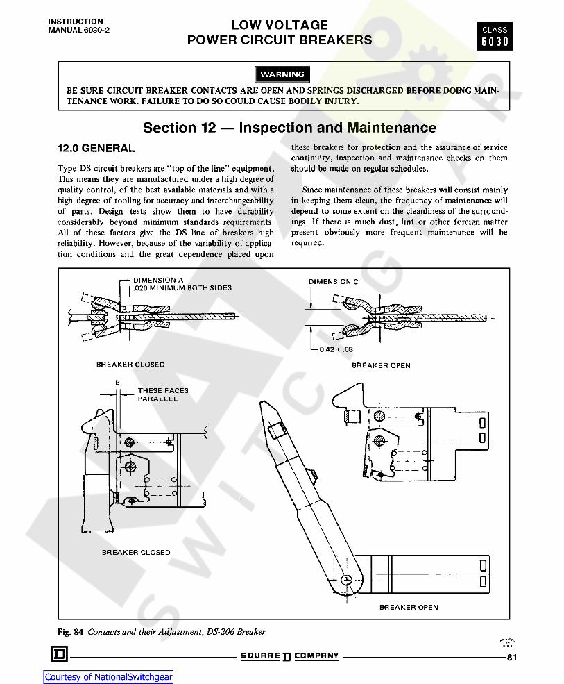
INSTRUCTIONMANUAL 6030-2 LOW VOLTAGE
POWER CIRCUIT BREAKERSCLASS
6 0 30
WARNING
BE SURE CIRCUIT BREAKER CONTACTS ARE OPEN AND SPRINGS DISCHARGED BEFORE DOING MAIN-TENANCE WORK. FAILURE TO DO SO COULD CAUSE BODILY INJURY.
Section 12 — Inspection and Maintenancethese breakers for protection and the assurance of servicecontinuity, inspection and maintenance checks on themshould be made on regular schedules.
12.0 GENERAL
Type DS circuit breakers are “top of the line” equipment.This means they are manufactured under a high degree ofquality control, of the best available materials and with ahigh degree of tooling for accuracy and interchangeabilityof parts. Design tests show them to have durabilityconsiderably beyond minimum standards requirements.All of these factors give the DS line of breakers highreliability. However, because of the variability of applica-tion conditions and the great dependence placed upon
Since maintenance of these breakers will consist mainlyin keeping them clean, the frequency of maintenance willdepend to some extent on the cleanliness of the surround-ings. If there is much dust , lint or other foreign matterpresent obviously more frequent maintenance will berequired.
Fig. 84 Contacts and their Adjustment, DS-206 Breakeru *o S Q U A R E D C O M P A N Y 81

LOW VOLTAGEPOWER CIRCUIT BREAKERS
INSTRUCTIONMANUAL 6030-2CLASS
6 0 3 0
12-1.1 When To Inspect tion shows, for instance, heavy accumulations of dirt orother foreign matter that might cause mechanical, insula-tion or other electrical damage, the inspection andmaintenance interval should be decreased.
When a breaker opens a heavy fault, at or near itsrating, give it a visual inspection withdrawn from thecompartment and with insulating barriers and arc chutesremoved.
Industry standards for this type of equipment recommenda general inspection and lubrication after the number ofoperations listed in Section 12.3.1 of this instructionbook. This should also be conducted at the end of thefirst six months of service if the number of operations hasnot been reached.
After the first inspection, inspect at least once a year.If these recommended inspections show no maintenancerequirements, the period may be extended to a moreeconomical point. Conversely, if the recommended inspec-
12.1.2 What To InspectFirst withdraw the breaker from the compartment.Remove barriers. Remove arc chutes. If there is a deposit
Fig. 85 Contacts and their Adjustment, DS-416/420 Breaker
•NU 3 * oSQUARE COMPANY82

INSTRUCTIONMANUAL 6030-2 LOW VOLTAGE
POWER CIRCUIT BREAKERSCLASS
6 0 3 0
breaker contact parts. A large accumulation of operationswill give the contacts, especially the arcing contacts, amottled, dirty, eroded appearance. This appearance is thenormal result of arc burning and in itself is no cause forconcern.
of dust, blow clean with compressed air, if available. Wipeaccessible areas with a clean dry doth. Inspect contacts.
Note: Switching and fault interruptions and the makingof motor inrush currents will cause some pitting of the
Fig. 86 Contacts and their Adjustment, DS-632 BreakerU 8.*-
S Q U R R E D C O M P A N Y 83

LOW VOLTAGEPOWER CIRCUIT BREAKERS
INSTRUCTIONMANUAL 6030-2CLASS
6 0 3 0
12.1 .2.1 DS-206, DS-206S, DS-416, DS-416S andDS-420
Close the breaker and check the contact engagementaccording to Figures 84 and 85. The main stationary con-tact fingers should be parallel (B) to the fixed contactcage. If not, adjust the contacts according to 12.2.3. Alsocheck the dimension (A) between the stationary arcingcontacts and the center section of the cage. If this dimen-sion is not .02 inches or greater, the stationary arcing con-tacts should be replaced.
Remove the barriers and the arc chutes to expose thecontacts:
With the breaker open, examine the contact tips ofmoving and stationary arcing and main contacts. If thetips are burned or worn more than .030", the contactsmust be replaced . Also check the dimension (C) betweenthe stationary arcing contacts (Figures 84 and 85). Itshould be .42 ± .08. If this dimension is not maintained,the stationary arcing contacts must be replaced.
Replace the barrier and the arc chutes after inspectionis completed.
NOTEThe DS-206 adjustments and maintenance apply com-pletely to the DS-206S. Also, the DS-420 instructionscover the DS-416S.
Fig. 87 Contacts and their Adjustment, DS-840 Breaker
i hu a * DSQUARE ]] COMPRNY84

INSTRUCTIONMANUAL 6030-2 LOW VOLTAGE
POWER CIRCUIT BREAKERSCLASS
6 0 3 0
12.1.3.2 DS-416, DS-416S, DS-420, DS-632 and DS-840
The moving arcing and main contacts are secured to themoving contact assembly by two bolts. Removal of thesebolts permits the replacement of the moving contacts.
To change the fixed arcing and main contacts, thefixed contact assembly must first be removed from thepole unit. Remove the disconnect fingers, remove thescrews holding the contact assembly to the pole unit baseand withdraw the contact assembly.
Obtain a new or reconditioned assembly and reassem-ble in the pole unit, with the holding screws finger tight.Close circuit breaker and check the dimensions A (Figures85, 86 and 87); they should be approximately equal. Ifnot, trip breaker and adjust fixed contact system untilalignment is obtained. Tighten screws and contacts asdescribed in 12.2.3.12.1.4 Arc Chutes
Fig. 88 Open Position Stop and Anti-Rebound Latch
To replace the stationary contacts, the disconnectfingers on the rear are removed and then the two boltsholding the upper contact assembly to the molded base.Withdraw the contact assembly from the front. Thisshould be replaced with a new contact assembly. Makesure that all bolts are securely tightened. Close the circuitbreaker and check all contact dimensions as described inSection 12.1.2.
The V-shaped slots in the arc chutes will undergo slowerosion with arc interruptions. Switching operations willgive them a pitted, mottled and sooty appearance. This isnormal. Heavy fault interruptions will cause greater arcerosion.12.1.2.2 DS-632 and DS-840
In addition to the requirements for the DS-206, DS-206S,DS-416, DS-416S and DS-420 above:
When the steel splitter plates have about 1/4 inch ofmaterial eroded away at the top of the V-shaped slots,they should be replaced. This can be determined bycomparing a plate near the center with a plate near theend. The insulating plates should be replaced at the sametime. This can be done easily by removing the topretaining strips, removing the worn plates and replacingwith new ones.
The lower main fixed contacts should be inspected toensure that they have adequate contact pressure. This isdetermined by pin “X” being free to slide in the contactcage (See Figures 86 and 87). Unlike DS-206/DS-416/DS-420 breakers, the top row of fixed main contacts arecompressed beyond parallel position to assure adequatecontact pressure for lower row of fixed main contacts. The throat of the insulating arc chute enclosure will
become eroded and sooted with operations. These areasshould be sanded with sandpaper and the enclosure blownout with air or brushed out, before installing new splitterplates. Occasionally the whole arc chute may needreplacing, depending upon the severity of duty.
12.1.3 Replacement Of Contacts
12.1.3.1 DS-206
Both moving main and arcing contacts are held betweenthe two moving arms by two bolts with self-locking nuts.Removal of the two bolts permits the replacement of themoving contacts. These bolts must be securely tightenedafter replacement.
12.1.5 General Inspection
Look over all visible parts possible for missing pinretainers, loose nuts, bolts or screws, bent, worn ordamaged parts. Make appropriate corrections to anythingfound out of order.The fixed arcing contacts are held by a single bolt
passing through the contacts and their pressure springs.On reassembly the self-locking nut is tightened so that adimension of 3.12 inches is obtained between the insidesurfaces of the flat washers on the spring ends.
After any inspection make sure all parts are properlyinstalled on the breaker, especially arc chutes and all fourbarriers.
**‘“ t*0mu *Q SQUARE ]] COMPANY 85

LOW VOLTAGEPOWER CIRCUIT BREAKERS
INSTRUCTIONMANUAL 6030-2CLASS
6 0 3 0
12.2 FACTORY ADJUSTMENTS(Required for Major Overhaul Only)
operations and normally encountered atmospheric tern-perature and dirt conditions.
The type DS circuit breakers are designed and built withvery few adjustable parts. The operating parts and framemounting parts are accurately tool made for automaticallyaccurate assembly relationships. The parts are made ofmaterial that are affected to the minimum by repeated
There are a few adjustments, made at the factory andsubjected to quality control inspection and test. Thesefactory settings normally can be expected to hold for thelife of the breaker.
Fig. 89 Levering Mechanism
U » A. DSQUARE COMPANY86

INSTRUCTIONMANUAL 6030-2 LOW VOLTAGE
POWER CIRCUIT BREAKERSCLASS
6 0 3 0
The moving pole of the DS416/420 is adjusted byrotating the insulating link after the lock nut has beenloosened. Refer to Figure 39. Tighten the locknut se-curely after the adjustment has been completed.
Factory settings are adjustments which should only benecessary when parts are reassembled after dismantling.These are described in Sections 12.2.1 and 12.2.2.
Maintenance adjustments should be made as indicatedon maintenance inspections and are described in Sec-tion 12.2.3.
The DS632 and DS840 have two adjusting studs oneach pole, and both must be moved together to retain theparallelism. Refer to Figures 43 and 45. A spring typelocking clip holds the adjustment for DS632. For DS840locking nuts similar to DS416/420 hold the adjustments.
12.2.1 Trip Latch Overlap
Figure 23a shows a composite view of the shunt trip leverand the trip latch, as described in Section 5.1.6. Theangular position of the trip shaft latch surface is adjust-able in relation to the trip latch surface by means of ascrew located in the top of the actuator frame. (Fig-ure 23b).
Check contact system as described in Section 12.1.2.
Proper adjustment procedure is as follows:
Close the breaker
Slowly rotate adjusting screw clockwise until thebreaker trips. This is “no overlap” position.
Rotate adjusting screw 4 turns in a counterclockwisedirection.
12.2.2 Breaker Open Position Stop (DS632 Only)
Proper Adjustment Procedure is as follows:
Refer to Figure 88With the breaker open, loosen the open position stop
bolt nuts so that the eccentric cylinders can be turned byhand but will stay put.
Fig. 90 Lubrication Points on Left Side of MechanismRotate the cylinders to obtain a clearance of approxi-mately .005 in. between the cylinders and the stop levers.Tighten nuts on bolts. 12.2.4 Levering Mechanism
The complete levering mechanism is shown in detail inFigure 89. If the traveling stop nut on the rear of theworm shaft has been removed, it must be replaced in theexact position with respect to the worm gear position forproper interlock operation. This is achieved when thethreaded worm shaft bottoms in the stop nut and theinterlock cam is in the connected position shown inFigure 29a. The shutter interlock pin will then drop to itsnormal position beneath the lobe of the cam. Theretaining clamp ring also operates the position indicatorand may be slipped in its groove in the stop nut. The stopnut is prevented from rotating by having a “flat” againstthe bottom of the breaker horizontal top pan.
12.2.3 Moving Contact Adjustment
The contact assemblies are adjustable for the amount ofengagement only. The lead of the arcing contacts over themain contacts is fixed. The correct engagement of thecontacts is achieved when the vertical faces of the mainfixed contacts and the fixed contact cage are parallel.
For the DS206 this is obtained by the adjusting nutslocated on the insulating link stud above and below thepivot block. Refer to Figures 37 and 38. These nuts areself-locking, and must be tight when the adjustment iscomplete.
D SQUARE COMPANY 87

LOW VOLTAGEPOWER CIRCUIT BREAKERS
INSTRUCTIONMANUAL 6030-2CLASS
6 0 3 0
top pan. This allows this mechanism to float. Screwsshould be tightened and then backed off 1/2 turn to allowmechanism to float.
WARNING
FAILURE TO INSPECT, CLEAN, LUBRICATEAND MAINTAIN CIRCUIT BREAKER AT REC-OMMENDED FREQUENCIES COULD RESULTIN FAILURE OF EQUIPMENT TO OPERATEPROPERLY UNDER FAULT CONDITIONS,WHICH COULD CAUSE EQUIPMENT DAM-AGE AND/OR BODILY INJURY.
12.3 LUBRICATIONIn general, the circuit breaker requires only moderatelubrication at regular intervals. The use of a speciallubricant is required in $ ifew places, and must be appliedwith care. Only small quantities are needed. All excessmust be removed with a clean cloth to prevent anyaccumulation of dust or dirt. Avoid any lubricant oninsulation or other electrical parts. Care must be taken toprevent any of the molybdenum lubricant reaching anycurrent carrying contact surface.
12.3.2 Location And Lubricant
Refer to Figures 90 and 91. The numbered referencesbelow correspond to those on the above figures.
Molykote M-30 dispersion by Dow Corning or mixtureof molybdenum disulphide and alcohol or equivalentshould be placed on the following surfaces. Oil base lu-bricants are generally avoided to prevent the accumulationof dust and dirt which will cause wear and binding in themechanism.
1. The spring-charge indicator surface engaging with thecut off switch link.2. The cam surface operating the cut-off switch link.
3. The pins on both ends of the constraining link.4. Shunt trip moving armature surface, Fig. 19c.5. The curved surface of the trip latch.6. Spring release moving armature surface, Fig. 19d.7. The trip shaft, Fig. 19c.8. The surface of the cut off switch link.9. The main spring pins on each end of the crankshaftand fixed ends.
Fig. 91 Lubrication Points on Right Side of MechanismNOTE
12.3.1 FrequencyType DS-206/DS-206S breaker after 1750 operations.Type DS-416/DS-416S/DS-420 breakers after 500 opera-tions.Type DS-632 and DS-840 breaker after 250 operations.
NOTEBreakers that have been stored or have infrequent opera-tions shall be operated a minimum of five times beforebeing placed in service.
All parts of the levering mechanism, Figure 89 have suffi-cient lubrication, and should not require any furtherattention.
WARNING
BE SURE CIRCUIT BREAKER CONTACTS AREOPEN AND CLOSING SPRINGS ARE DIS-CHARGED AFTER COMPLETING MAINTE-NANCE WORK. FAILURE TO DO SO COULDCAUSE BODILY INJURY.
U S- *- mSQUARE ]] COMPANY88

INSTRUCTIONMANUAL 6030-2 LOW VOLTAGE
POWER CIRCUIT BREAKERSCLASS
6 0 3 0
Section 13 — Renewal Parts13.0 GENERAL drawing) are used for the same purpose in Type DS-416S.
Description of these parts are the same too, but they areidentified as parts for DS-416S (or shop order number).Bulletin 6030-3, listing by name and style number the
recommended renewal parts to be kept in stock, aresupplied separate from this book. When ordering parts,always specify the part name and style number, if known,from the Bulletin 6030-3. If the style number is notknown, refer to the Figure number, name and item num-ber as shown in this book, along with the breaker typeand shop order number or style number as shown on thenameplate on the front cover of the circuit breaker.
13.1.2 DS-206S Parts
The parts of Type DS-206S are very similar to those ofDS-206. By reference to the proper DS-206 figure (ordrawing) identification of their common parts can bemade. When they are ordered for the DS-206S, it is sospecified. The major differences are:
Some of the detail parts shown in the figures in this bookwill be available only as part of a sub-assembly. The detailparts in the figures are illustrated to show their functionand location in the assembly; but certain parts, due tomanufacturing procedures or installation procedures, arerecommended and furnished as part of a sub-assembly.The renewal parts data indicates which parts are availableas individual items or in a sub-assembly . When inquiringabout or ordering parts, refer to the figures in this bookand the renewal parts data for identification of the part orsub-assembly in question.
1. DS-206S uses the three piece base of the DS-416, in-stead of the one piece molded base of the DS-206.
2. DS-206S uses the DS-416 arc chute.
3. DS-206S main disconnects have 50% more fingers thanthe DS-206.
4. DS-206S has twice as many contacts and arms as theDS-206.
5. The pole unit hinge of DS-206S is a forked construc-tion or a miniature version of the DS-416 hinge.13.1 IDENTIFYING PARTS FOR DS-416S
and DS-206S
13.1.1 DS-416S Parts
The parts of a DS-416S are almost identical to those of aDS-420. The parts shown in a proper DS-420 figure (or
*U ft.*-IQ SQUAREDCOMPRNY 89

SQUARE COMPANYP.O. Box 558, Middletown, Ohio 45042
Manual 6030-2 Printed in U.S.A.3M 6/90 CPS