Embed Size (px)
Citation preview

508 01 1202 01 01/28/10
Installation, Start−Up and Service Instructions
3 Phase, 50 Hz
BHC & HBC Series Heat Pump Air Handlers, 7−1/2 to 15 TonBAC & ABC Series Air Conditioner Air Handler, 20 Ton
IMPORTANT — READ BEFORE INSTALLING
1 . Read and become familiar with these installation instruc-tions before installing this unit.
2. Be sure the installation conforms to all applicable local andnational codes.
3. These instructions contain important information for theproper maintenance and repair of this equipment. Retainthese instructions for future use.
CONTENTSPage
SAFETY CONSIDERATIONS 1,2PRE−INSTALLATION 2. . . . . . . . . . . . . . . . . . . . . . . . . Rigging 2. . . . . . . . . . . . . . . . . . . . . . . . . . . . . . . . . . . . . Installation 2-23. . . . . . . . . . . . . . . . . . . . . . . . . . . . . . . . . . General 2. . . . . . . . . . . . . . . . . . . . . . . . . . . . . . . . . . . . . Uncrating 2. . . . . . . . . . . . . . . . . . . . . . . . . . . . . . . . . . . Accessories 2. . . . . . . . . . . . . . . . . . . . . . . . . . . . . . . . . Model Nomenclature 2. . . . . . . . . . . . . . . . . . . . . . . . . . Unit Positioning 2. . . . . . . . . . . . . . . . . . . . . . . . . . . . . . Unit Isolation 3. . . . . . . . . . . . . . . . . . . . . . . . . . . . . . . . Refrigerant Piping 3. . . . . . . . . . . . . . . . . . . . . . . . . . . . Condensate Drain 8. . . . . . . . . . . . . . . . . . . . . . . . . . . . Fan Motors and Drives 8. . . . . . . . . . . . . . . . . . . . . . . . Power Supply and Wiring 9. . . . . . . . . . . . . . . . . . . . . . Connecting Ductwork 9. . . . . . . . . . . . . . . . . . . . . . . . . Return−Air Filters 9. . . . . . . . . . . . . . . . . . . . . . . . . . . . Start−Up 11. . . . . . . . . . . . . . . . . . . . . . . . . . . . . . . . . . . . Service 11. . . . . . . . . . . . . . . . . . . . . . . . . . . . . . . . . . . . . Panels 11. . . . . . . . . . . . . . . . . . . . . . . . . . . . . . . . . . . . . . Fan Motor Lubrication 11. . . . . . . . . . . . . . . . . . . . . . . . . Fan Shaft Bearings 11. . . . . . . . . . . . . . . . . . . . . . . . . . . Centering Fan Wheel 11. . . . . . . . . . . . . . . . . . . . . . . . . Fan Shaft Position Adjustment 11. . . . . . . . . . . . . . . . . Individual Fan Wheel Adjustment 12. . . . . . . . . . . . . . . Fan Belts 12. . . . . . . . . . . . . . . . . . . . . . . . . . . . . . . . . . . . Fan Rotation 12. . . . . . . . . . . . . . . . . . . . . . . . . . . . . . . . . Fan Pulley Alignment 13. . . . . . . . . . . . . . . . . . . . . . . . . Pulley and Drive Adjustment 13. . . . . . . . . . . . . . . . . . . Condensate Drains 13. . . . . . . . . . . . . . . . . . . . . . . . . . . Coil Removal 13. . . . . . . . . . . . . . . . . . . . . . . . . . . . . . . . Cleaning Cooling Coil 13. . . . . . . . . . . . . . . . . . . . . . . . . Replacing Filters 17. . . . . . . . . . . . . . . . . . . . . . . . . . . . . Cleaning Insulation 18. . . . . . . . . . . . . . . . . . . . . . . . . . . Start−Up Checklist 19. . . . . . . . . . . . . . . . . . . . . . . . . . . Parts 21−23. . . . . . . . . . . . . . . . . . . . . . . . . . . . . . . . . . . . . . .
SAFETY CONSIDERATIONS
WARNINGImproper installation, adjustment, alteration, service,maintenance, or use can cause explosion, fire, electricshock, or other occurrences which may injure you ordamage your property. Consult qualified installer or ser-vice agency for information or assistance. The qualifiedinstaller or agency must use only factory-authorized kitsor accessories when modifying this product.
Understand the signal words — DANGER, WARNING, andCAUTION. These words are used with the safety-alert symbol.Danger identifies the most serious hazards which will result insevere personal injury or death. Warning indicates a conditionthat could result in personal injury. Caution is used to identifyunsafe practices which would result in minor personal injury orproduct and property damage.
Installing, starting up, and servicing this equipment can behazardous due to system pressures, electrical components andequipment location (elevated structures, etc.).
Only trained, qualified installers and service mechanicsshould install, start up, and service this equipment.
Untrained personnel can perform basic maintenance func-tions such as cleaning coils, and cleaning and replacing filters.All other operations should be performed by trained servicepersonnel.
When working on the equipment, observe precautions in theliterature and on tags, stickers, and labels attached to theequipment.1. Follow all safety codes.2. Wear safety glasses and work gloves.3. Use care in handling, rigging, and setting bulky equipment.
WARNING
Be sure all power to equipment is shut off before per-forming maintenance or service. More than one discon-nect may be present.
1. The power supply (v, ph, and Hz) must correspond to thatspecified on unit rating plate.
2. The electrical supply provided by the utility must be suffi-cient to handle load imposed by this unit.
3. This installation must conform with local building codesand with the NEC (National Electrical Code) or ANSI(American National Standards Institute)/NFPA (NationalFire Protection Association) latest revision. Refer to pro-vincial and local plumbing or wastewater codes and otherapplicable local codes.

Air HandlersInstallation Instructions
2
MODEL NUMBER IDENTIFICATION GUIDE FOR MODEL NUMBERS THAT BEGIN WITH ‘B’MODEL NUMBER B H C 090 Z 1 A
PRODUCT FAMILY Engineering DigitAir Handler Units
BLOWER DRIVE OPTIONSTYPE 1 = Medium Static DriveH= Heat PumpA = Air Conditioner VOLTAGE
Z = 400-3-50. . . . . . . . . . . . . . . . . DESIGN SERIES
COOLING CAPACITY (NOMINAL BTUH)090 = 7−1/2 120 = 10 Ton. . . . . . . . . . . . . . . . . . . . . . . 180 = 15 Ton 240 = 20 Ton. . . . . . . . . . . . . . . . . . . . .
MODEL NUMBER IDENTIFICATION GUIDE FOR MODEL NUMBERS THAT BEGIN WITH ‘A or H’MODEL NUMBER H B C 090 M 1 A
TYPE Engineering DigitH= Heat PumpA = Air ConditionerPackaged BLOWER DRIVE OPTIONS
1 = Medium Static DrivePRODUCT FAMILY Air Handler Units VOLTAGE
Z = 400-3-50DESIGN SERIES
COOLING CAPACITY (NOMINAL BTUH)090 = 7−1/2 120 = 10 Ton . . . . . . . . . . . . . . . . . . . . . . . 180 = 15 Ton 240 = 20 Ton. . . . . . . . . . . . . . . . . . . . . .
PRE-INSTALLATION
Rigging All units can be rigged by using the shipping skid.Units are shipped fully assembled. Do not remove shippingskids or protective covering until unit is ready for final place-ment; damage to bottom panels can result. Use slings andspreader bars as applicable to lift unit.
INSTALLATION
General Allow 21/2 ft at front and side of unit for serviceclearance and airflow. For units equipped with an economizer,refer to the accessory installation instructions for additionalclearance requirements. Be sure floor, wall, or ceiling cansupport unit weight.
Uncrating Move unit as near as possible to final location be-fore removing shipping skid.
Remove metal banding, top skid, and plastic wrap. Examineunit for shipping damage. If shipping damage is evident, fileclaim with transportation agency. Remove base skid just prior toactual installation.
NOTE: Be sure to remove the styrofoam shipping pad from thethermostatic expansion valve (TXV). Verify that it has been re-moved. See Fig. 1.
Accessories Refer to instructions shipped with each acces-sory for specific information.
Figure 1 Styrofoam Shipping Pad Removal
Unit Positioning The unit can be mounted on the floor forvertical application with return air entering the face of the unitand supply air discharging vertically through the top of the unit.The unit can also be applied in a horizontal arrangement withreturn air entering horizontally and the supply air discharginghorizontally. When applying the unit in a horizontal arrange-ment, ensure the condensate drain pan is located at the bot-tom center of the unit for adequate condensate disposal. SeeFig. 2 for condensate connections for each unit position.
Typical positioning and alternate return air locations areshown in Fig. 2. Alternate return air locations can be used bymoving the unit panel from the alternate return air location tothe standard return air location. Refer to overhead suspensionaccessory drawing (Fig. 3) for preferred suspension technique.The unit needs support underneath to prevent sagging.

Air Handlers Installation Instructions
3
IMPORTANT: Do NOT attempt to install unit withreturn air entering top panel of unit. Condensatewill not drain from unit.
Figure 2 Typical Unit Positioning
Accessory Line
Alternate Air Intake and Discharge
Air Intake and Discharge
Unit Isolation Where extremely quiet operation is essential,install isolators between floor and base of unit, or between ceil-ing and top section of unit.
Be sure that unit is level and adequately supported. Usechannels at front and sides of unit for reference points whenleveling.
Refrigerant Piping For ease in brazing, it is recommendedthat all internal solder joints be made before unit is placed infinal position.
The direct-expansion units have internal factory-installedthermostatic expansion valves (TXVs), distributors, and nozzlesfor use with R-22. Knockouts are provided in the unit cornerposts for BAC/ABC and BHC/HBC090 and 120 refrigerant pip-ing. The BHC/HBC0180 unit requires additional field-fabricatedpiping access holes. See Fig. 4, which also lists recommendedknockouts and access holes to use for each BAC/ABC andBHC/HBC unit size. Recommended fittings are listed in Table 1.
The sensor bulb capillary tubes must be routed from theTXVs inside the unit through one of the piping access holes.Clamp the TXV sensor bulb on a vertical portion of the suctionline, outside the unit. See Fig. 5.
NOTE: Be sure to remove the styrofoam shipping pad from theTXV. Verify that it has been removed. See Fig. 1.
IMPORTANT: Never attach the sensor to the suc-tion manifold. Do NOT mount the sensor on atrapped portion of the suction line.
The BAC/ABC Series evaporator coils have a face-split de-sign. Ensure that lower circuit of coil is first on/last off whenconnected to the condensing unit and/or system controls. SeeFig. 6.
External TXV equalizer connections are provided andfactory-brazed into the coil suction manifolds.
If suction line must be horizontal, clamp bulb to suction lineat least 45 degrees above bottom, at approximately the4 o’clock or 8 o’clock position. See Fig. 7.
NOTE: The BHC/HBC units are supplied with factory-installedthermostatic expansion valves and check valve bypasses. Noextra piping connections or kits are required to install the BHC/HBC with a CHC/HCC condensing unit in a heat pump
system, however, some field supplied components may be re-quired. See the following two sections.CHC/HCC090 with BHC/HBC090 HEAT PUMP SYSTEMPIPING Addition of a liquid solenoid valve (LLSV) is recom-mended when the piping system length exceeds 75 feet. TheLLSV must be a bi-flow type suited for use in heat pumpsystems. The recommended valve is Sporlan model CB14S2 (5/8-in. ODF, 7/8-in. ODM). This solenoid valve requires Spor-lan part no. MKC-2 coils that must be purchased locally. Wirethe solenoid valve in parallel with the compressor contactor coil.
The LLSV must be installed at the outdoor unit with the flowarrow pointed toward the outdoor unit (in-flow direction for theheating mode.)

Air HandlersInstallation Instructions
4
NOTE: Dimensions in [ ] are millimeters.
Fig. 3 Preferred Suspension Technique
UNIT SIZES 7−1/2 to 10 Ton
UNIT SIZES 15 to 20
UNIT SIZES 028,034
OVERHEAD SUSPENSION ACCESSORY

Air Handlers Installation Instructions
5
Table 1: Fitting Requirements
UNIT ACCESSHOLE NO.*
CONNECTIONTYPE CIRCUIT FITTINGS REQUIRED†
(in.)
BHC/HBC090
1 Suction —
11/8 Street Elbow
11/8 Nipple, 85/8 L
11/8 Long Radius Elbow
3 Liquid —
5/8 Street Elbow5/8 Nipple, 85/8 L5/8 Long Radius Elbow
BHC/HBC120
1 Suction Lower (2) 11/8 Street Elbow
2 Liquid Lower
5/8 Street Elbow5/8 Nipple, 51/2 L5/8 Long Radius Elbow
3 Liquid Upper
5/8 Street Elbow5/8 Nipple, 101/2 L5/8 Long Radius Elbow
4 Suction Upper
11/8 Nipple, 55/8 L
11/8 Long Radius Elbow
11/8 Nipple, 12 L
11/8 Long Radius Elbow
BHC/HBC180
3 Suction Lower11/8 Nipple, 3 L
11/8 Long Radius Elbow
5 Liquid Lower
5/8 Nipple, 27/8 L5/8 45° Elbow5/8 Nipple, 15/8 L5/8 Long Radius Elbow
6 Liquid Upper
5/8 Nipple, 27/8 L5/8 45° Elbow5/8 Nipple, 41/4 L5/8 Long Radius Elbow
7 Suction Upper
11/8 Nipple, 5 L
11/8 45° Elbow
11/8 Nipple, 83/4 L
11/8 Long Radius Elbow
BAC/ABC240
1 Suction Lower
11/8 Street Elbow
11/8 Nipple, 75/8 L
11/8 Long Radius Elbow
2 Liquid Lower
5/8 Street Elbow5/8 Nipple, 61/2 L5/8 Long Radius Elbow
3 Liquid Upper
5/8 Street Elbow5/8 Nipple, 91/2 L5/8 Long Radius Elbow
4 Suction Upper
11/8 Nipple, 55/8 L
11/8 Long Radius Elbow
11/8 Nipple, 11 L
11/8 Long Radius Elbow
Table 1 — Fitting Requirements*See Fig. 4 for access hole location by number.†Fittings are listed in order from header or tee stub connection out to acesshole in corner support post.

Air HandlersInstallation Instructions
6
UNITUse HoleNumbers
Field Fabricated Hole Diameters in. (mm) Field Fabricated Hole Position Dimensions, In.(mm)No. 5 No. 6 No. 7 No. 8 A B C D
BHC/HBC0901, 3 − − − − − − − −
BAC/ABC240BHC/HBC120 1, 2, 3, 4 − − − − − − − −BHC/HBC180 3*, 5, 6, 7 1−1/8
(28.6 )1−1/8(28.6)
1−3/4(44.5) −
3.25 (82.6)
6.125(155.6)
10.38(263.7) −
*Must be enlarged from 11/8 in. to 13/4 inches.NOTE: Access hole knockouts 1-4 are factory-supplied.
Fig. 4 — Refrigerant Piping Access Holes
LEGENDTXV — Thermostatic Expansion ValveNOTE: Component location arrangement shown for field installation ofsight glasses, solenoid valves, filter driers, and TXV sensing bulbs. TheTXVs and equalizer lines are factory installed.
Fig. 5 — Face-Split Coil Suction and Liquid Line Piping(Typical)

Air Handlers Installation Instructions
7
FIRST ON/LAST OFF = BVERTICAL INSTALLATION
FIRST ON/LAST OFF = AHORIZONTAL INSTALLATION
Fig. 6 — Typical Evaporator Coil Connections(BAC/ABC, BHC/HBC)
LEGENDTXV — Thermostatic Expansion ValveNOTE: The 8 o’clock position is shown above.
Fig. 7 — TXV Sensing Bulb Location

Air HandlersInstallation Instructions
8
Condensate Drain Install a trapped condensate drain lineto unit connection as shown in Fig. 9. The unit drain connectionis a PVC stub. See Fig. 10. Some areas may require an adapt-er to connect to either galvanized steel or copper pipe. Forthese applications, install a field-supplied threaded PVC adapt-er.
NOTE: A trap must be installed in the condensate drain line toensure that the static pressure of fans is balanced with the wa-ter column in the drain line and that condensate can draincompletely from pan. Without a trap, air can be drawn up drainline until water level in condensate pan becomes equal to staticpressure created by fans, preventing complete drainage. Con-ditions will worsen as filters become dirty.
Install clean-out plugs in trap. Pitch drain line downward toan open floor drain or sump. Provide service clearance arounddrain line to permit removal of unit panels. Observe all localsanitary codes.
NOTE: As shipped, the unit’s condensate drain pan is NOTsloped towards the drain connection. The pan slope must bechanged to pitch towards the side of the unit with the drain con-nection. See Fig. 10. Loosen the 2 screws next to the drain out-let at both ends of the unit, push drain pan down in the slotsnear the drain connection, and up in the slots on the oppositeend. Retighten screws. The pan should have a pitch of at least1/4-in. over its length toward the drain connection.
Fig. 9 — Drain Pan Slope Adjustment
NOTE: Dimensions in [ ] are in millimeters.
Fan Motors and Drives Motor and drive packages arefactory installed in all units. The standard motor and drive pack-ages consist of the following items:
1 — fan motor1 — adjustable motor pulley1 — fan pulley1 — fan belt (BHC/HBC090−180 units)2 — matched fan belts (BAC/ABC240 units)For instructions on changing fan rotation, changing drive
speeds and adjusting drives, see Pulley and Drive Adjustmentin the Service section.
Fig. 10 — Condensate Drains

Air Handlers Installation Instructions
9
Power Supply and Wiring Check the unit data plate toensure that available power supply matches electrical charac-teristics of the unit. Provide a disconnect switch of size requiredto provide adequate fan motor starting current.
Install disconnect switch and power wiring in accordancewith all applicable local codes. See Fig. 11-13 and the unitlabel diagram. For units with motor sizes less than 5 Hp(3.7 kW), connect power wiring to unit with no. 10 ring terminal.For units with motor sizes of 5 Hp (3.7 kW) or more, connectpower wiring with 1/4-in. ring terminal.
LEGENDTXV — Thermostatic Expansion Valve
Fig. 11 — Wiring and Service Access(Side Panel Removed)
FILTERELEMENTS
FILTERRETAINERCLIP
FAN SCROLL
CONDENSATEDRAINCONNECTION(HORIZONTAL)
MOTORAND DRIVE
FANCONTACTORBOX
WIREACCESS
COIL
FAN DRIVEPULLEY
TXV BULBACCESS
REFRIGERANT/CHILLED WATERPIPING ACCESS
CONDENSATEDRAINCONNNECTION(VERTICAL)
RefrigerantPiping Access
Fan motors are factory installed on all units. Indoor-fan con-tactors are located in the fan contactor box behind the sideaccess panel (see Fig. 11 and 12). Wire the thermostat to the24-v control circuit terminal block located in the side of the fancontactor control box, according to Fig. 13 or the unit labeldiagram. If the air handler is part of a split system, complete thewiring from the condensing unit to the thermostat shown in Fig.14.
Fig. 12 — Fan Contactor Box and Terminal BlockCover Removed (Typical)
23 22 21
13 12 11
105
° C600V
RJ
A
W
FANCONTACTOR
24VTERMINALBLOCK
POWERWIRINGKNOCKOUT
Table 2 — Fan Contactor Coil Data
UNITBAC/ABC, BHC/HBC
VOLTAGE(vac)
MAXIMUMHOLDING
VA
6 to 20 Ton 24 10
Connecting DuctworkDISCHARGE CONNECTIONS Duct flanges are factory sup-plied; they are shipped inside the unit attached to the hairpinend of the coil tube sheet for field installation. Using the existingscrews, install the duct flanges on the unit’s fan deck. Each fandischarge requires 2 flanges; each flange must be bent in themiddle to conform to the discharge opening. See Fig. 14. Afterflanges are installed, connect them to the supply duct using acanvas connection to prevent vibration. It is important that thisconnection be properly fabricated to prevent high air frictionlosses and air noise.
RETURN CONNECTION When using return-air ductwork,route return-air duct to the unit’s return air inlet near the filterrack, using a canvas connection to prevent transmission of unitvibration. If the duct blocks off the unit’s access panel, provide aslip joint in the ductwork to permit removal for servicing.
OUTDOOR-AIR INLET CONNECTION Connect outdoor-airinlet to field-installed accessory economizer. Refer to economiz-er Installation Instructions.
Return-Air Filters Air filters are factory-supplied andinstalled. In all units with 2 fans, a filter replacement tool (hook)is shipped inside the unit for field use when replacing filters.See the Service section for instructions on filter element re-placement.

Air HandlersInstallation Instructions
10
Fig. 13 — Unit Wiring
LEGENDEQUIP Equipment. . . GND Ground. . . . . HC Heating Contactor. . . . . . HTR Electric Heater. . . . . IFC Indoor Fan Contactor. . . . . . IFM Indoor Fan Motor. . . . . . TB Terminal Block. . . . . . T’STAT Thermostat. . . Factory Wiring. . . . Field Control Wiring. . NOTE: Use copper conductors only.
Fig. 14 — Duct Flange Connection
BHC/HBC Only
BAC/ABCBHC/HBC
Terminal BlockTB1

Air Handlers Installation Instructions
11
START-UP
Before starting unit, check the following and correct as nec-essary:− Is unit solidly supported?− Is fan adjusted for speed and pulley alignment?− Are pulleys, motor, and bearings securely mounted?− Are there any loose parts that will rattle or vibrate?− Is condensate drain pan pitched for correct drainage?− Are coil baffle plates tight against coil to prevent air by-
pass?− Are all panels securely fastened?− Are all electrical connections correct and tight?
Also refer to condensing unit instructions before starting asplit system. A split system start-up checklist is provided in theback of these instructions.
SERVICE
Inspection and maintenance should be performed at regularintervals and should include the following:− Complete cleaning of cabinet, fan wheel, cooling coil,
condensate pan and drain, heating coils, and return-airgrille (if present).
− Inspection of panels and sealing of unit against airleakage.
− Adjustment of fan motor, belt, bearings, and wheels.− Cleaning or replacement of filters.− Testing for cooling/heating system leaks.− Checking of all electrical connections.
Most unit service can be performed by removing one or bothof the unit’s side panels. Coil cleaning or removal or insulationcleaning may require removal of a rear, top, or bottom panel,depending on the unit’s orientation. When service is completed,replace unit panels.
Panels Panels are fastened to unit frame with sheet metalscrews. Fan and coil compartment must be sealed tightly afterservice to prevent air from bypassing the cooling coil.
Fan Motor Lubrication Fan motor supplied with unit ispermanently lubricated and requires no further lubrication.
Fan Shaft Bearings Bearings on 7−1/2 to 10 ton units aresealed, permanently lubricated bearings that require no furtherlubrication. 15 to 20 ton units have pillow-block bearings (Fig.15) that must be lubricated with suitable bearing greaseapproximately every 3 months. See Table 3 for suitable lubri-cants.
Table 3 — Lubricant Data
MANUFACTURER LUBRICANT
Mobil Mobilplex EP No. 2
Sunoco Prestige 42
Texaco Multifak 2
Texaco Regal AFB-2*
*Preferred lubricant because it contains rust and oxidation inhibitors.
Fig. 15 — Fan Shaft, Bearings, and Fan Wheel(Typical)
Fig. 16 — Fan Shaft Bearing
Centering Fan Wheel If fan and fan shaft assembly arenot properly centered, blades may scrape against scroll or maycreate an objectionable whistling noise. It may be necessary toadjust individual fan wheels or move entire fan shaft. See thefollowing two sections.
Fan Shaft Position Adjustment Loosen setscrew orlocking collar of each fan shaft bearing. Slide shaft into correctposition and replace locking collar (Fig. 16). To replace lockingcollar, push collar up against inner face of bearing. Turn collarin direction of fan rotation until tight, and tighten setscrew. Tight-ening locking collar in direction of fan rotation results in furthertightening of collar should setscrew work itself loose.

Air HandlersInstallation Instructions
12
Individual Fan Wheel Adjustment Loosen the 2 lock-ing bolts holding fan wheel hub to shaft. See Fig. 15. Positionfan wheel in center of the fan housing and tighten locking bolts.Clearance between wheel and housing should be the same onboth sides.
Fan Belts Motor mounting plate and motor support anglesare slotted to permit both vertical and horizontal adjustment.Adjust belt(s) for correct deflection by loosening motor platemounting bolts, moving motor/plate assembly forward or back,and retightening bolts. Press down on belt with one finger mid-way between fan and motor pulleys to check deflection. Forunits with motor sizes up to and including 3.7 Hp (2.76 kW),correct deflection is 3/16-in. (4.8 mm) For larger motor sizes,correct deflection is 1/8-in. (3.2 mm). See Fig. 17.
If complete belt replacement is required during servicing,loosen the motor plate mounting bolts (Fig. 18), move motor/plate assembly towards fan pulley, and pull belt(s) off pulleys.Reverse the procedure with new bolts and readjust deflection.
Fan Rotation Correct fan rotation with respect to fan outletis shown in Fig. 18.
To reverse the direction of rotation of a 3-phase fan motor,reverse any 2 of the power leads. Refer to the connection dia-gram on the inside of motor terminal box cover for proper re-versing procedure of single-phase motor.
Fig. 17 — Fan Motor Mounting

Air Handlers Installation Instructions
13
Fig. 18 — Fan Rotation
Fig. 19 — Fan Pulley AdjustmentsFan Pulley Alignment Align as follows:
1. Loosen setscrews on pulleys.
2. Align pulleys visually and tighten setscrews on fan pulleyto lock it in place.
3. Use the methods shown in Fig. 19 to check proper pulleyalignment.
4. If pulleys are not in correct alignment, loosen the motorholddown bolts and slide the motor axially until the pulleysare aligned.
5. Tighten motor holddown bolts.
Pulley and Drive Adjustment To obtain desired fanspeed, refer to the fan motor and drive data in Tables 8A-10Dand adjust fan motor pulley as follows:
1. Remove belt from fan motor pulley after loosening motorfrom motor base.
2. Loosen setscrew in moveable flange of pulley. Screwmoveable flange toward fixed flange to increase the fan
speed and away from fixed flange to reduce speed. Be-fore tightening setscrew, make certain that setscrew isover nearest flat surface of pulley hub (Fig. 19).
Increasing fan speed produces a greater load onmotor. Do not exceed rated capacity of motor.
Condensate Drains Keep condensate drains free of dirtand foreign matter.
Return-Air Filters Refer to Replacing Filters section for fil-ter accessibility and removal. Replace with clean filters.
Coil Removal Remove unit panels and corner posts as re-quired. Disconnect coil connections and remove fasteningscrews. Remove coil through end or side sections of unit.
Cleaning Cooling Coil Remove return-air filters. Removeany heavy dirt that may have accumulated on underside of coil.Coil can be cleaned more easily with a stiff brush, vacuumcleaner, or compressed air when coil is dry. If coil is wet or ifwater is to be used for cleaning, guard against splashing wateron electrical components or damaging surrounding area. Cleancoil baffles as applicable and check for tight fit to be sure airdoes not bypass coil.
Cleaning Insulation The insulation contains an immobi-lized antimicrobial agent that helps prevent the growth ofbacteria and fungi. Clean the inner surface of the insulationaccording to the maintenance instructions in this manual.

Air HandlersInstallation Instructions
14
Table 4A — Fan Motor Data, — English, SI
Fan Motor Data − Medium Static − English Fan Motor Data − Medium Static − SIUNIT BHC/HBC090 BHC/HBC120 BHC/HBC180 BAC/ABC240 BHC/HBC090 BHC/HBC120 BHC/HBC180 BAC/ABC240
Volt−Ph−Hz 400−3−50 400−3−50Speed (rpm) 1725 1725 1725 1745 28.75 28.75 28.75 29.08
Hp 2.0 2.0 3.0 5.0 1.49 1.49 2.24 3.73
Frame(NEMA) 56HZ 56HZ 56HZ 184T 56HZ 56HZ 56HZ 184T
Shaft Dia (in.) 7/8
7/8
7/8 11/
8 22.2 22.2 22.2 28.6
LEGEND NEMA — National Electrical Manufacturers Association
Table 4B — Medium-Static Drive Data, 50 Hz — English
UNIT BHC/HBC090 BHC/HBC120 BHC/HBC180 BAC/ABC240MOTOR DRIVE
Motor Pulley Pitch Diameter (in.) 3.4-4.4 3.4-4.4 3.7-4.7 4.3-5.3Pulley Factory SettingFull Turns Open 2.5 2.5 3.0 3.0
FAN DRIVEPulley Pitch Dia (in.) 8.0 8.0 8.6 9.4Pulley Bore (in.) 1 1 17/
16 17/16
Belt No. — Section 1—A 1—A 1—B 2—BBelt Pitch (in.) 40.3 40.3 41.8 41.8
FAN SPEEDS (rpm)Factory Setting 794 926 756 916Range 692 − 896 808 − 1045 667 − 848 814 − 1018Max Allowable Speed (rpm) 1200 1200 1200 1200Change per 1/
2 Turn ofMoveable Motor Pulley Flange
20.4 23.7 15.1 20.4
MAX FULL TURNS FROMCLOSED POSITION 5 5 6 5
SHAFTS CENTER DISTANCE (in.) 10.44 - 12.32 10.44 - 12.32 10.44 - 12.32 9.16 - 10.99
Table 4B — Medium-Static Drive Data, 50 Hz — SI
UNIT BHC/HBC090 BHC/HBC120 BHC/HBC180 BAC/ABC240MOTOR DRIVE
Motor Pulley Pitch Diameter (mm) 86.4-111.8
86.4-111.8
94.0-119.4
109.2-134.6
Pulley Factory SettingFull Turns Open 2.5 2.5 3.0 3.0
FAN DRIVEPulley Pitch Dia (mm) 203 203 218 239Pulley Bore (mm) 25.4 25.4 36.5 36.5Belt No. — Section 1—A 1—A 1—B 2—BBelt Pitch (mm) 1024 1024 1062 1062
FAN SPEEDS (r/s)Factory Setting 13.2 15.4 12.6 15.3Range 11.5 − 14.9 13.5 − 17.4 11.1 − 14.1 13.6 − 17.0Max Allowable Speed (r/s) 20.0 20.0 20.0 20.0Change per 1/2 Turn ofMoveable Motor Pulley Flange 0.340 0.395 0.252 0.340
MAX FULL TURNS FROMCLOSED POSITION 5 5 6 5
SHAFTS CENTER DISTANCE (mm) 265-313 265-313 265-313 232-279

Air Handlers Installation Instructions
15
Table 5A — Fan Performance Data — 0.0-1.2 in. wg ESP — 50 Hz, ENGLISH
UNIT AIRFLOW(Cfm)
EXTERNAL STATIC PRESSURE (in. wg)0.0 0.2 0.4 0.6 0.8 1.0 1.2
Rpm Bhp Rpm Bhp Rpm Bhp Rpm Bhp Rpm Bhp Rpm Bhp Rpm Bhp
BHC/HBC090
�2,250 359 0.32 472 0.44 560 0.55 634 0.65 700 0.75 759 0.86 814 0.96
�2,600 415 0.45 516 0.57 599 0.68 669 0.79 732 0.90 790 1.01 843 1.11
�3,000 478 0.62 569 0.75 645 0.86 712 0.98 773 1.09 828 1.20 879 1.32
�3,400 542 0.82 624 0.95 695 1.08 758 1.20 815 1.31 869 1.43 918 1.55
�3,750 598 1.03 673 1.17 740 1.29 800 1.42 855 1.60 906 1.66 954 1.78
BHC/HBC120
�3,000 471 0.61 564 0.74 642 0.86 710 0.97 771 1.09 827 1.20 878 1.31
�3,500 550 0.87 632 1.00 703 1.13 766 1.25 824 1.37 877 1.49 926 1.60
�4,000 628 1.17 701 1.31 766 1.44 825 1.57 879 1.69 930 1.82 978 1.94
�4,500 706 1.53 772 1.67 832 1.81 887 1.94 938 2.07 987 2.20 1032 2.33
�5,000 785 1.93 845 2.08 900 2.22 952 2.36 1000 2.50 1045 2.63 1089 2.76
BHC/HBC180
�4,500 405 0.54 507 0.79 592 1.03 667 1.28 735 1.54 797 1.80 854 2.06
�5,300 476 0.85 566 1.13 643 1.40 713 1.68 776 1.97 835 2.26 890 2.55
�6,000 539 1.20 620 1.50 691 1.81 756 2.11 816 2.42 872 2.73 924 3.05
�6,800 611 1.69 683 2.03 748 2.36 809 2.69 865 3.03 918 3.37 968 3.71
�7,500 674 2.22 740 2.58 800 2.93 857 3.29 910 3.65 960 4.02 1008 4.38
BAC/ABC240
�6,000 503 1.07 587 1.37 661 1.67 727 1.97 789 2.28 846 2.59 900 2.90
�7,000 586 1.64 660 1.98 726 2.31 787 2.65 844 2.99 898 3.33 948 3.67
�8,000 670 2.37 735 2.74 795 3.12 851 3.49 904 3.86 954 4.23 1001 4.61
�9,000 754 3.28 812 3.69 867 4.09 918 4.50 967 4.90 1014 5.31 1059 5.72
10,000 838 4.39 891 4.83 941 5.27 988 5.70 1034 6.14 1077 6.85 1120 7.02
Table 5B — Fan Performance Data — 1.4-2.4 in. wg ESP — 50 Hz English
UNIT AIRFLOW(Cfm)
EXTERNAL STATIC PRESSURE (in.wg)1.4 1.6 1.8 2.0 2.2 2.4
Rpm Bhp Rpm Bhp Rpm Bhp Rpm Bhp Rpm Bhp Rpm Bhp
BHC/HBC090
�2,250 865 1.06 913 1.16 958 1.27 1001 1.37 1042 1.47 — —
�2,600 893 1.22 940 1.33 984 1.43 1027 1.54 1067 1.65 — —
�3,000 928 1.43 973 1.54 1017 1.65 1058 1.76 1098 1.87 — —
�3,400 965 1.66 1010 1.78 1052 1.89 1092 2.00 1131 2.12 — —
�3,750 1000 1.90 1043 2.02 1084 2.13 1124 2.25 1162 2.37 — —
BHC/HBC120
�3,000 927 1.43 973 1.54 1017 1.65 1058 1.76 1098 1.87 1137 1.98
�3,500 973 1.72 1018 1.84 1060 1.95 1101 2.07 1139 2.18 1177 2.30
�4,000 1023 2.06 1066 2.19 1107 2.31 1146 2.43 1184 2.55 — —
�4,500 1075 2.45 1116 2.58 1156 2.71 1194 2.83 — — — —
�5,000 1130 2.90 1170 3.03 — — — — — — — —
BHC/HBC180
�4,500 908 2.33 959 2.61 1008 2.89 1054 3.17 1098 3.46 1141 3.75
�5,300 941 2.84 991 3.14 1038 3.45 1082 3.75 1126 4.06 1167 4.38
�6,000 974 3.36 1022 3.69 1067 4.01 1111 4.34 1153 4.67 1193 5.00
�6,800 1015 4.05 1061 4.40 1104 4.75 1146 5.10 1187 5.46 — —
�7,500 1054 4.75 1098 5.12 1140 5.49 1181 5.86 — — — —
BAC/ABC240
�6,000 950 3.21 999 3.53 1045 3.85 1089 4.17 1131 4.50 1172 4.83
�7,000 996 4.02 1042 4.37 1086 4.72 1129 5.07 1169 5.43 — —
�8,000 1047 4.99 1091 5.37 1133 5.75 1173 6.13 — — — —
�9,000 1102 6.13 1143 6.54 1183 6.96 — — — — — —
10,000 1160 7.46 1200 7.91 — — — — — — — — LEGENDBhp — Brake Horsepower Input to Fan
ESP — External Static Pressure
Bold indicates field-supplied drive is required.Plain type indicates standard motor and standard drive.Underline indicates a different motor and drive combination other than thestandard motor and standard drive combination is required. Refer to fanmotor and drive tables, pages 33-36, to complete selection.
NOTES:1. Fan performance is based on deductions for wet coil, clean 2-in. fil-
ters, and unit casing. See table at right for factory-supplied filter pres-sure drop.
Factory Supplied Filter Pressure Drop _ English
UNIT AIRFLOW(Cfm)
PRESSURE DROP(in. wg)
BHC/HBC090
2,2503,0003,750
0.070.110.15
BHC/HBC120
3,0004,0005,000
0.110.170.23
BHC/HBC180
4,5006,0007,500
0.080.120.17
BAC/ABC0240
6,0008,000
10,000
0.120.190.26

Air HandlersInstallation Instructions
16
Table 5C — Fan Performance Data — 0-300 Pa ESP — 50 Hz, SI
UNITAIRFLOW
(L/s)
EXTERNAL STATIC PRESSURE (Pa)0 50 100 150 200 250 300
r/s kW r/s kW r/s kW r/s kW r/s kW r/s kW r/s kW
BHC/HBC090
1000 5.63 0.22 7.61 0.30 9.11 0.38 10.40 0.45 11.50 0.53 12.50 0.61 13.40 0.681200 6.76 0.32 8.49 0.41 9.88 0.50 11.10 0.57 12.10 0.66 13.10 0.74 14.00 0.821400 7.89 0.46 9.42 0.55 10.70 0.64 11.80 0.72 12.80 0.81 13.80 0.89 14.60 0.971600 9.01 0.62 10.40 0.71 11.60 0.80 12.60 0.89 13.60 0.98 14.50 1.07 15.30 1.161800 10.10 0.80 11.40 0.90 12.50 0.10 13.50 1.09 14.40 1.18 15.20 1.27 16.00 1.36
BHC/HBC120
1450 8.04 0.49 9.57 0.58 10.90 0.67 12.00 0.76 13.00 0.85 13.90 0.93 14.80 1.021670 9.26 0.67 10.60 0.77 11.80 0.86 12.90 0.95 13.80 1.04 14.70 1.13 15.50 1.221900 10.50 0.89 11.80 0.99 12.80 1.09 13.80 1.19 14.70 1.28 15.60 1.38 16.40 1.472120 11.80 1.14 12.90 1.24 13.90 1.35 14.80 1.45 15.60 1.55 16.40 1.64 17.20 1.742350 13.00 1.43 14.00 1.54 15.00 1.65 15.80 1.75 16.60 1.85 17.40 1.95 18.10 2.05
BHC/HBC180
2100 6.65 0.39 8.39 0.58 9.83 0.76 11.10 0.95 12.20 1.13 13.30 1.31 14.20 1.502450 7.76 0.60 9.30 0.81 10.60 1.01 11.80 1.22 12.90 1.43 13.80 1.63 14.80 1.842800 8.87 0.86 10.20 1.09 11.50 1.32 12.50 1.55 13.60 1.78 14.50 2.01 15.40 2.243150 9.98 1.19 11.20 1.44 12.30 1.70 13.40 1.95 14.30 2.20 15.20 2.45 16.00 2.703500 11.10 1.59 12.20 1.86 13.20 2.14 14.20 2.41 15.10 2.68 15.90 2.95 16.70 3.22
BAC/ABC240
2900 8.58 0.86 9.96 1.09 11.20 1.32 12.30 1.55 13.30 1.78 14.20 2.01 15.10 2.253350 9.91 1.28 11.10 1.53 12.20 1.79 13.20 2.04 14.20 2.30 15.10 2.55 15.90 2.813800 11.30 1.81 12.30 2.09 13.30 2.37 14.30 2.64 15.10 2.93 16.00 3.21 16.80 3.494250 12.60 2.46 13.60 2.76 14.50 3.07 15.30 3.37 16.10 3.67 16.90 3.98 17.70 4.284700 13.90 3.24 14.80 3.57 15.60 3.90 16.40 4.22 17.20 4.55 17.90 4.88 18.60 5.21
Table 5D — Fan Performance Data — 350-600 Pa ESP — 50 Hz, SI
UNITAIR-
FLOW(L/s)
EXTERNAL STATIC PRESSURE (Pa)350 400 450 500 550 600
r/s kW r/s kW r/s kW r/s kW r/s kW r/s kW
BHC/HBC090
1000 14.30 0.76 15.10 0.83 15.80 0.91 16.60 0.99 17.30 1.06 — —1200 14.80 0.90 15.60 0.98 16.40 1.05 17.10 1.13 17.80 1.21 — —1400 15.40 1.06 16.20 1.14 16.90 1.22 17.60 1.30 18.30 1.39 — —1600 16.10 1.24 16.80 1.33 17.50 1.41 18.20 1.50 18.90 1.58 — —1800 16.80 1.45 17.50 1.54 18.20 1.63 18.90 1.72 19.50 1.80 — —
BHC/HBC120
1450 15.60 1.10 16.30 1.18 17.10 1.27 17.80 1.35 18.40 1.43 19.10 1.521670 16.30 1.31 17.00 1.40 17.80 1.48 18.40 1.57 19.10 1.66 19.70 1.741900 17.10 1.56 17.80 1.65 18.50 1.74 19.20 1.83 19.80 1.92 — —2120 17.90 1.83 18.60 1.93 19.30 2.02 19.90 2.11 — — — —2350 18.80 2.15 19.50 2.25 — — — — — — — —
BHC/HBC180
2100 15.10 1.68 16.00 1.87 16.80 2.06 17.50 2.24 18.30 2.43 19.00 2.622450 15.60 2.05 16.40 2.25 17.20 2.46 18.00 2.67 18.70 2.88 19.40 3.092800 16.20 2.47 17.00 2.69 17.80 2.92 18.50 3.15 19.20 3.38 19.80 3.613150 16.80 2.95 17.60 3.19 18.30 3.44 19.00 3.69 19.70 3.94 — —3500 17.50 3.49 18.20 3.76 19.00 4.03 19.60 4.30 — — — —
BAC/ABC240
2900 16.00 2.49 16.80 2.73 17.50 2.97 18.30 3.22 19.00 3.47 19.70 3.723350 16.70 3.08 17.50 3.34 18.20 3.61 18.90 3.87 19.60 4.14 — —3800 17.50 3.77 18.20 4.06 18.90 4.35 19.60 4.64 — — — —4250 18.40 4.59 19.10 4.90 19.80 5.21 — — — — — —4700 19.30 5.54 20.00 5.87 — — — — — — — —
LEGEND
ESP — External Static Pressure
Bold indicates field-supplied drive is required.
Plain type indicates standard motor and standard drive.
Underline indicates a different motor and drive combination other than thestandard motor and standard drive combination is required. Refer to fanmotor and drive tables, pages 33-36, to complete the selection.
NOTES:1. Fan performance is based on deductions for wet coil, clean 51-mm fil-
ters, and unit casing. See table at right for factory-supplied filter pres-sure drop.
FACTORY-SUPPLIED FILTER PRESSURE DROP — SI
UNIT AIRFLOW(L/s)
PRESSURE DROP(Pa)
BHC/HBC090100014001800
172738
BHC/HBC012145019002350
284256
BHC/HBC180210028003500
203042
BAC/ABC240290038004700
324764

Air Handlers Installation Instructions
17
Fig. 20 — Remove Filter Retainer Clip
Fig. 21 — Filter Removal/Replacement
FILTERRETAINERCLIP
SLIDE
Do not operate unit without air filters.
Table 6A: Factory-Supplied Filter Pressure Drop — English
UNIT AIRFLOW(Cfm)
PRESSURE DROP(in. wg)
BHC/HBC090
�2,250�3,000�3,750
0.070.110.15
BHC/HBC120
�3,000�4,000�5,000
0.110.170.23
BHC/HBC180
�4,500�6,000�7,500
0.080.120.17
BAC/ABC240
�6,000 0.12
�8,000 0.19
10,000 0.26
Table 6B: Factory-Supplied Filter Pressure Drop — SI
UNIT AIRFLOW(L/s)
PRESSURE DROP(Pa)
BHC/HBC090
100150001800
172738
BHC/HBC120
145019002350
284256
BHC/HBC180
210028003500
203042
BAC/ABC240
2900 32
3800 47
4700 64
Replacing Filters Filters can be removed and installedfrom either side of the unit. Install new filters in units that haveone fan as follows:
1. Remove the side access panel (retain screws).
2. Remove the filter retainer clip (see Fig. 20).
3. Remove old filters by lifting and tilting them out of the filtertrack. See Fig. 21.
4. Reverse the procedure to install new filters.
To install new filters in larger units that have 2 fans, followthe preceding steps, but use the factory-supplied filter hook toslide filters within reach for removal. The filter hook is shippedinside the unit in the filter track.

Air HandlersInstallation Instructions
18
Commercial Packaged Units With Schuller Tuf−Skin RX� Insulation
Maintenance Instructions
ELECTRIC SHOCK HAZARDTo avoid the possibility of electrical shock,open and tag all disconnects before per-forming maintenance on this equipment.
INTRODUCTIONSchuller Tuf−Skin RX insulation is now a standard feature in
many of our units, including 6 to 20 ton packaged air handlers.The Tuf−Skin Rx insulation has an acrylic coating impregnatedwith an anti−microbial agent. This insulation construction pro-vides an important benefit: The insulation resists the growth ofbacteria and fungi, thereby helping to maintain indoor air quali-ty. The insulation also provides other benefits, including re-duced noise and elimination of condensate sweating.
The best way to ensure that the packaged unit continues toprovide these benefits is t use an efficient, properly maintainedfilter system. A regular inspection schedule helps to identify po-tential problems such as incorrect or dirty filters or moisture−causing sources.
BEFORE CLEANING UNIT
Problems discovered during a routine maintenance inspec-tion can include dirty filters, dirty insulation, moisture leaks, andfungi growth. Other types of problems may be present but noteasily detectable. High levels of CO2 and volatile organic com-pounds are not visible; specialized sensors must be used todetect excessive levels of these pollutants.
Once a problem has been identified, it should be correctedbefore remedial cleaning is performed. Problem correction maybe as simple as replacing filters more frequently or adjustingthe slope of the drain pan. More complex problems may requiresome system modifications. After identifying and correctingproblems as necessary, the unit can be cleaned.
CLEANING METHODS
Before cleaning the inside of the unit, disconnect all unitpower. Remove access panels from the sides of the unit to gainaccesss to the unit interior. See the base unit installation in-structions for panel and interior component locations.
Cleaning Insulation − There are several general methods cur-rently in use for cleaning HVAC systems. The three most com-mon and effective methods are contact vacuuming, airwashing, and power brushing. Use one of these methods or acombination of these methods to clean the Tuf−Skin Rx insula-tion.
CONTACT VACUUMING − Use a portable vacuum (shop vac)with a long hose and brush head to remove dirt manually.Maintain light, direct contact between the brush head and theinterior insulation surfaces to dislodge and remove dirt. Thismethod can allow the escape of dust and dirt form the equip-ment during cleaning, because the systems is not subjected tonegative pressure.
AIR WASHING − Compressed air can be used to dislodge dirtand debris from the insulation while vacuum equipment collectsthe dirt downstream. Because this method uses negative pres-
sure, dirt and dust are not as likely to escape from the systemduring cleaning. Use a long hose with a ‘skipper’ nozzle to dis-lodge the dirt so that it becomes airborne and is collected bythe vacuum equipment. Limit the air pressure to the nozzle toensure that the insulation is not damaged.
POWER BRUSHING − Use an electrically or pneumaticallypowered rotating brush to loosen dirt and debris while collectingthe airborne dirt downstream from the unit with vacuum equip-ment. Use a soft bristle brush with care to ensure that the in-sulation is not damaged during cleaning. As with the previousair washing method, this method also creates negative pres-sure so that dirt is not expelled form the system during clean-ing.
When Cleaning Other Areas of the Unit − Unit componentssuch as coils and drain pans are often cleaned during routinemaintenance. Cleaning methods can include the use of clean-ing solutions combined with pressure washing to remove accu-mulated dirt. When pressure washing any are of the unit, donot spray water or cleaning solutions directly on the unit insula-tion. If the insulation becomes wet, wipe it down with a dampcloth or sponge. Before putting the unit back into service, makesure the insulation and all unit surfaces are full dry.
After the unit interior has been cleaned and dried, problemareas remedied, and filters replaced, reassemble the unit sidepanes and restore power to the unit.
Additional Information − For additional details on cleaning in-sulated HVAC systems, contact the North American InsulationManufacturer’s Association, Alexandria, VA. Refer to NAIMA’spublication no. AH−122, Cleaning Fibrous Glass Insulated AirDuct Systems.

Air Handlers Installation Instructions
19
START-UP CHECKLIST
(SPLIT SYSTEMS WITH BAC/ABCand BHC/HBC UNITS)
I. PRELIMINARY INFORMATIONOUTDOOR: MODEL NO.
SERIAL NO.
INDOOR: MODEL NO.
SERIAL NO.
ADDITIONAL ACCESSORIES
II. PRE-START-UPOUTDOOR UNIT
IS THERE ANY SHIPPING DAMAGE? (Y/N)
IF SO, WHERE:
WILL THIS DAMAGE PREVENT UNIT START-UP? (Y/N)
CHECK POWER SUPPLY. DOES IT AGREE WITH UNIT? (Y/N)
HAS THE GROUND WIRE BEEN CONNECTED? (Y/N)
HAS THE CIRCUIT PROTECTION BEEN SIZED AND INSTALLED PROPERLY? (Y/N)
ARE THE POWER WIRES TO THE UNIT SIZED AND INSTALLED PROPERLY? (Y/N)
CONTROLS
ARE THERMOSTAT(S) AND INDOOR FAN CONTROL WIRINGCONNECTIONS MADE AND CHECKED? (Y/N)
ARE ALL WIRING TERMINALS (including main power supply) TIGHT? (Y/N)
HAVE OUTDOOR UNIT CRANKCASE HEATERS BEEN ENERGIZED FOR 24 HOURS? (Y/N)
INDOOR UNIT
HAS WATER BEEN PLACED IN DRAIN PAN TO CONFIRM PROPER DRAINAGE? (Y/N)
ARE PROPER AIR FILTERS IN PLACE? (Y/N)
HAVE FAN AND MOTOR PULLEYS BEEN CHECKED FOR PROPER ALIGNMENT? (Y/N)
DO THE FAN BELTS HAVE PROPER TENSION? (Y/N)
PIPING
BAC/ABC, BHC/HBC
HAS FOAM SHIPPING BLOCK BEEN REMOVED FROM THE TXV (Thermostatic Expansion Valve)? (Y/N)
ARE LIQUID LINE SOLENOID VALVES LOCATED AT THE INDOOR UNIT COILS AS REQUIRED? (Y/N)
HAVE LEAK CHECKS BEEN MADE AT COMPRESSORS, CONDENSERS, INDOOR COILS,TXVs (Thermostatic Expansion Valves) SOLENOID VALVES, FILTER DRIERS, AND FUSIBLE PLUGSWITH A LEAK DETECTOR? (Y/N)
LOCATE, REPAIR, AND REPORT ANY LEAKS.
HAVE ALL COMPRESSOR SERVICE VALVES BEEN FULLY OPENED (BACKSEATED) (Y/N)
ARE THE COMPRESSOR OIL SIGHT GLASSES SHOWING CORRECT LEVELS? (Y/N)
BAC/ABC, BHC/HBC
HAS AIR BEEN BLED FROM SYSTEM? (Y/N)
HAVE LEAK CHECKS BEEN MADE AT COMPRESSORS, VALVES, AND INDOOR COILS? (Y/N)
LOCATE, REPAIR, AND REPORT ANY LEAKS.

Air HandlersInstallation Instructions
20
CHECK VOLTAGE IMBALANCE
LINE-TO-LINE VOLTS: AB V AC V BC V
(AB + AC + BC)/3 = AVERAGE VOLTAGE = V
MAXIMUM DEVIATION FROM AVERAGE VOLTAGE = V
VOLTAGE IMBALANCE = 100 X (MAX DEVIATION)/(AVERAGE VOLTAGE) = %
IF OVER 2% VOLTAGE IMBALANCE, DO NOT ATTEMPT TO START SYSTEM!CALL LOCAL POWER COMPANY FOR ASSISTANCE.
III. START-UP
CHECK INDOOR FAN MOTOR SPEED AND RECORD.
AFTER AT LEAST 10 MINUTES RUNNING TIME, RECORD THE FOLLOWING MEASUREMENTS:
COMP A1 COMP B1SUCTION PRESSURE
SUCTION LINE TEMP
DISCHARGE PRESSURE
DISCHARGE LINE TEMP
ENTERING OUTDOOR UNIT AIR TEMP
LEAVING OUTDOOR UNIT AIR TEMP
INDOOR UNIT ENTERING AIR DB TEMP
INDOOR UNIT ENTERING AIR WB TEMP
INDOOR UNIT LEAVING AIR DB TEMP
INDOOR UNIT LEAVING AIR WB TEMP
COMPRESSOR AMPS (L1/L2/L3) ____/____/____ ____/____/____
NOTES:

Air Handlers Installation Instructions
21
Parts List on page 23
Illustration for reference only,your unit may differ from theone shown.
PARTS ILLUSTRATION FOR 7−1/2 TO 10 TON UNITS
Air HandlersInstallation Instructions
22
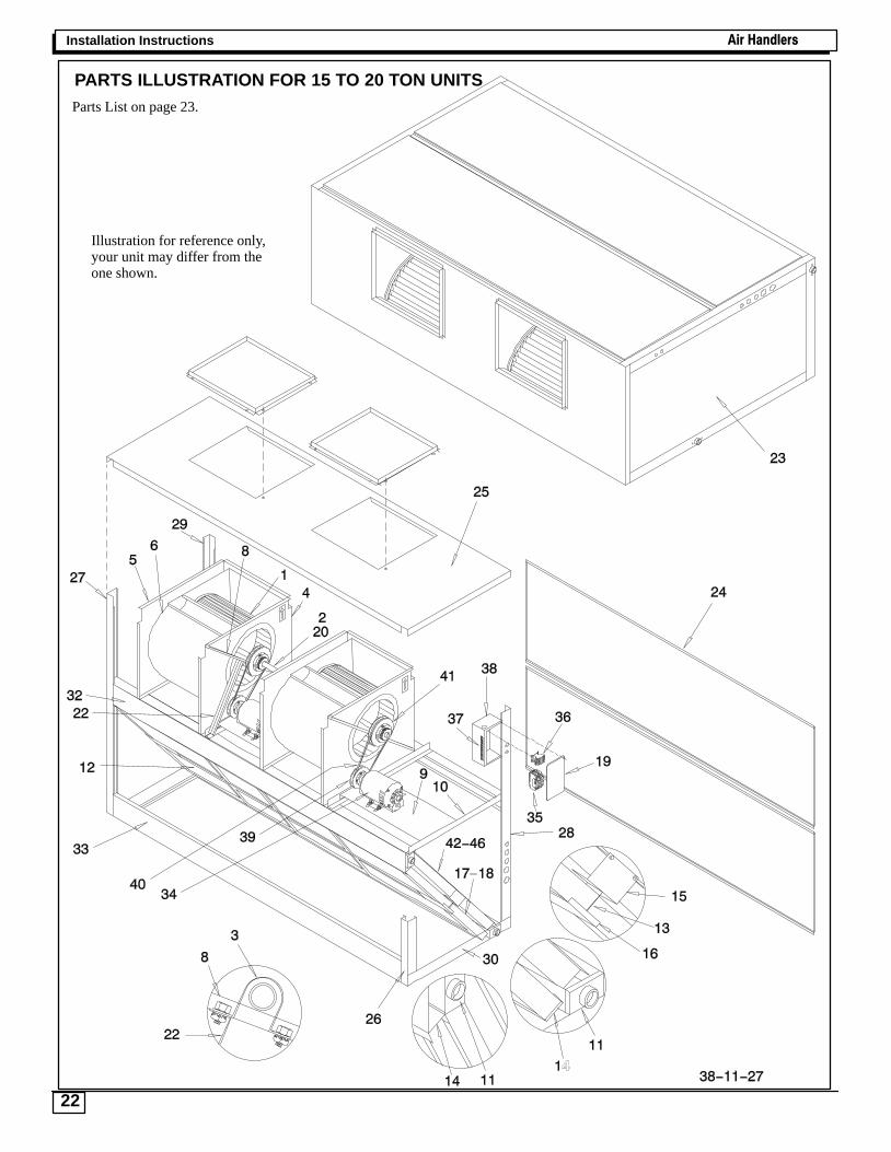
Parts List on page 23.
Illustration for reference only,your unit may differ from theone shown.
PARTS ILLUSTRATION FOR 15 TO 20 TON UNITS

Air Handlers Installation Instructions
23