Embed Size (px)
Citation preview

Manufacturer reserves the right to discontinue, or change at any time, specifications or designs without notice and without incurring obligations.Catalog No. 04-53390006-01 Printed in U.S.A. Form 39S-2SI Pg 1 7-08 Replaces: 39S-1SI
Installation, Start-Up and Service InstructionsCONTENTS
PageSAFETY CONSIDERATIONS . . . . . . . . . . . . . . . . . . . . . 1,2 INTRODUCTION. . . . . . . . . . . . . . . . . . . . . . . . . . . . . . . . . 2-17Unit Identification . . . . . . . . . . . . . . . . . . . . . . . . . . . . . . . . . . 2 PREINSTALLATION . . . . . . . . . . . . . . . . . . . . . . . . . . . . 18,19Rigging . . . . . . . . . . . . . . . . . . . . . . . . . . . . . . . . . . . . . . . . . . . 18 Shipping Bolt and Screw Removal . . . . . . . . . . . . . . . . 18 Unit Suspension . . . . . . . . . . . . . . . . . . . . . . . . . . . . . . . . . . 18Service Clearance . . . . . . . . . . . . . . . . . . . . . . . . . . . . . . . . 18Condensate Drain. . . . . . . . . . . . . . . . . . . . . . . . . . . . . . . . . 18External Vibration Isolators . . . . . . . . . . . . . . . . . . . . . . . 18INSTALLATION. . . . . . . . . . . . . . . . . . . . . . . . . . . . . . . . . 19-33Condensate Drain. . . . . . . . . . . . . . . . . . . . . . . . . . . . . . . . . 19Bottom Return Economizer Package (BREP) and
Horizontal Bottom Return EconomizerPackage (HBREP) . . . . . . . . . . . . . . . . . . . . . . . . . . . . . . . 19
Motorized Outside Air Damper . . . . . . . . . . . . . . . . . . . . 22Mixing Box Actuator (for 39SH and 39SM Horizontal
Return Units Only) . . . . . . . . . . . . . . . . . . . . . . . . . . . . . . 23• MIXING BOX ACTUATOR ASSEMBLY• ACTUATOR INSTALLATIONMixing Box Air Sensor . . . . . . . . . . . . . . . . . . . . . . . . . . . . 25• MIXING BOX MIXED AIR SENSOR BRACKET
ASSEMBLY• MIXED AND OUTSIDE AIR SENSORS
INSTALLATIONMixing Box. . . . . . . . . . . . . . . . . . . . . . . . . . . . . . . . . . . . . . . . 25• MIXING BOX LINKAGE INSTALLATION
(39SH Sizes 00-03)• MIXING BOX LINKAGE INSTALLATION
(Sizes 04-17)Install Sheaves on Motor and Fan Shafts . . . . . . . . . 27• ALIGNMENTInstall V-Belts . . . . . . . . . . . . . . . . . . . . . . . . . . . . . . . . . . . . . 28Water and Steam Coil Piping
Recommendations. . . . . . . . . . . . . . . . . . . . . . . . . . . . . . 29• GENERAL• WATER COILS• STEAM COILSCoil Freeze-Up Protection. . . . . . . . . . . . . . . . . . . . . . . . . 31Refrigerant Piping, Direct Expansion
(DX) Coils. . . . . . . . . . . . . . . . . . . . . . . . . . . . . . . . . . . . . . . 32Electric Heaters . . . . . . . . . . . . . . . . . . . . . . . . . . . . . . . . . . . 33Motor Stop/Start Stations . . . . . . . . . . . . . . . . . . . . . . . . . 33START-UP. . . . . . . . . . . . . . . . . . . . . . . . . . . . . . . . . . . . . . . . . 34Check List . . . . . . . . . . . . . . . . . . . . . . . . . . . . . . . . . . . . . . . . 34SERVICE . . . . . . . . . . . . . . . . . . . . . . . . . . . . . . . . . . . . . . 34,35General . . . . . . . . . . . . . . . . . . . . . . . . . . . . . . . . . . . . . . . . . . . 34Fan Motor Replacement. . . . . . . . . . . . . . . . . . . . . . . . . . . 34Coil Cleaning . . . . . . . . . . . . . . . . . . . . . . . . . . . . . . . . . . . . . 34• DETERGENTWinter Shutdown (Chilled Water Coil Only) . . . . . . . 34• ANTIFREEZE METHODS OF COIL PROTECTION• AIR DRYING METHOD OF COIL PROTECTION• PIPING
PageFilters . . . . . . . . . . . . . . . . . . . . . . . . . . . . . . . . . . . . . . . . . . . . .35• FILTER SECTIONSLubrication. . . . . . . . . . . . . . . . . . . . . . . . . . . . . . . . . . . . . . . .35• MOTORS• BEARINGS
SAFETY CONSIDERATIONSAir-handling equipment is designed to provide safe and reli-
able service when operated within design specifications. Toavoid injury to personnel and damage to equipment or propertywhen operating this equipment, use good judgment and followsafe practices as outlined below.
DANGER
NEVER enter an enclosed fan cabinet or reach into a unitwhile the fan is running.LOCK OPEN AND TAG the fan motor power disconnectswitch before working on a fan. Take fuses with you andnote removal on tag. Electric shock can cause personalinjury or death.LOCK OPEN AND TAG the electric heat coil power dis-connect switch before working on or near heaters.Failure to follow these warnings could lead to personalinjury or death.
WARNING
CHECK the assembly and component weights to besure that the rigging equipment can handle them safely.Note also, the centers of gravity and any specific rigginginstructions.CHECK for adequate ventilation so that fumes will notmigrate through ductwork to occupied spaces when weld-ing or cutting inside air-handling unit cabinet or plenum.WHEN STEAM CLEANING COILS be sure that the areais clear of personnel.DO NOT attempt to handle access covers and removablepanels on outdoor units when winds are strong or gustinguntil you have sufficient help to control them. Make surepanels are properly secured while repairs are being made toa unit.DO NOT remove access panel fasteners until fan is com-pletely stopped. Pressure developed by a moving fan cancause excessive force against the panel which can injurepersonnel.DO NOT work on dampers until their operators aredisconnected.BE SURE that fans are properly grounded before workingon them.Failure to follow these warnings could result in personalinjury or equipment damage.
39SH,SV,SM,SR00-17Indoor and Outdoor Air Handlers

2
INTRODUCTION
Unit Identification — The 39S units are identified bythe 18-digit part number listed on the serial plate. The partnumber describes all component, coil, motor, drive, and controlselections.
For further information on unit and component identifica-tion, contact your Carrier representative for the AHUBuilder®
program. Refer to the 39S Product Data catalog for more infor-mation on individual component sections. Refer to Tables 1-4and Fig. 1-13 for component data.
Table 1 — Physical Data — 39SH Coil and Filter Data
*4 and 6 row hot water coils have the same face area as 4 and 6 rowchilled water coils.†Single circuited coil.**Dual circuited coil.
CAUTION
SECURE drive sheaves with a rope or strap before work-ing on a fan to ensure that rotor cannot free-wheel.DO NOT restore power to unit until all temporary walk-ways inside components have been removed.NEVER pressurize equipment in excess of specified testpressures.PROTECT adjacent flammable material when welding orflame cutting. Use sheet metal or asbestos cloth to containsparks. Have a fire extinguisher at hand and ready forimmediate use.Failure to follow these warnings could result in personalinjury or equipment damage.
39SH UNIT SIZE 00 01 02 03 04 05 07 09 13 17CHILLED WATER
Nominal Capacity at 400 fpm (cfm) 632 716 800 1224 1612 2000 2916 3832 5500 7084Face Area (sq ft) 1.58 1.79 2 3.06 4.03 5 7.29 9.58 13.75 17.71Coil Connection Size (in. OD sweat)
4 Row (Qty) 3/4 3/4 3/4 3/4 7/8 11/8 11/8 13/8 13/8 15/8 (2) 6 Row (Qty) 3/4 3/4 3/4 7/8 11/8 11/8 13/8 15/8 15/8 15/8 (2)
HOT WATERNominal Capacity at 400 fpm (cfm) 632 716 624 956 1612 2000 2688 3544 5348 6640Face Area (sq ft) 1.58 1.79 1.56 2.39 4.03 5 6.72 8.86 13.37 16.6Coil Connection Size (in. OD sweat)
1 Row 5/8 5/8 5/8 5/8 7/8 7/8 N/A N/A N/A N/A2 Row (Qty) 7/8 7/8 7/8 7/8 7/8 11/8 11/8 13/8 13/8 15/8 (2) 4 Row* (Qty) 3/4 3/4 3/4 3/4 7/8 11/8 11/8 13/8 13/8 15/8 (2)6 Row* (Qty) 3/4 3/4 3/4 7/8 11/8 11/8 13/8 15/8 15/8 15/8 (2)
DIRECT EXPANSIONNominal Capacity at 400 fpm (cfm) 452 476 820 1220 1612 2000 2864 4088 5500 6640Face Area (sq ft) 1.13 1.19 2.05 3.05 4.03 5 7.16 10.22 13.75 16.6Connection Size (in. OD sweat) (Qty)
Liquid Line 1/4 1/4 3/8 3/8 1/2 1/2 5/8†,1/2** (2)
5/8†,1/2** (2)
1/2** (2) 5/8** (2)
Suction Line 3/4 3/4 3/4 3/4 7/8 11/8 11/8†, 7/8** (2)
13/8†,7/8** (2)
11/8** (2) 13/8** (2)
STEAM Nominal Capacity at 400 fpm (cfm) 632 716 752 1144 1452 1800 2688 3640 5512 7000Face Area (sq ft) 1.58 1.79 1.88 2.86 3.63 4.5 6.72 9.1 13.78 17.5
FILTER DATASize (in.) (Qty) 12x25 12x25 16x32 16x32 20x20
(2)20x20
(2)16x32 (2)20x32 (1)
16x32 (2)20x32 (1)
20x25 (2)20x20 (4)
16x20 (2)16x25 (2)20x20 (2)20x25 (2)
Nominal Face Area (sq ft) 2.08 2.08 3.56 3.56 5.56 5.56 11.56 11.56 18.06 22.5

3
Table 2 — Physical Data — 39SV Coil and Filter Data
Table 3 — Physical Data — 39SM Coil and Filter Data
*4 and 6 row hot water coils have the same face area as 4 and 6 rowchilled water coils.
39SV UNIT SIZE 02 03 04 05 07 09CHILLED WATER
Nominal Capacity at 400 fpm (cfm) 1200 1200 1600 2000 2932 3668Face Area (sq ft) 3 3 4 5 7.33 9.17Coil Connection Size (in. OD sweat) 3/4 3/4 7/8 11/8 11/8 13/8
HOT WATERNominal Capacity at 400 fpm (cfm) 804 804 964 1276 2292 3124Face Area (sq ft) 2.01 2.01 2.41 3.19 5.73 7.81Coil Connection Size (in. OD sweat) 7/8 7/8 7/8 11/8 11/8 11/8
DIRECT EXPANSIONNominal Capacity at 400 fpm (cfm) 1200 1200 1600 2000 2932 3668Face Area (sq ft) 3 3 4 5 7.33 9.17Connection Size (in. OD sweat) (Qty)
Liquid Line 3/8 3/8 1/2 1/2 5/8 1/2 (2)Suction Line 3/4 3/4 7/8 11/8 11/8 7/8 (2)
STEAMNominal Capacity at 400 fpm (cfm) 624 624 688 1268 1750 2452Face Area (sq ft) 1.56 1.56 1.72 3.17 4.375 6.13
FILTER DATASize (in.) (Qty) 20x20 20x20 22.5x22.5 16x25 (2) 20x25 (4) 20x25 (4)Nominal Face Area (sq ft) 2.78 2.78 3.52 5.56 13.89 13.89
39SM UNIT SIZE 04 05 07 09 13 17CHILLED WATER
Nominal Capacity at 400 fpm (cfm) 1668 2084 2776 3332 5000 7084Face Area (sq ft) 4.17 5.21 6.94 8.33 12.5 17.71Coil Connection Size (in. OD sweat)
4 Row (Qty) 7/8 11/8 11/8 13/8 13/8 15/8 (2)6 Row (Qty) 11/8 11/8 13/8 15/8 15/8 15/8 (2)
HOT WATERNominal Capacity at 400 fpm (cfm) 1668 2084 2776 3332 5000 7084Face Area (sq ft) 4.17 5.21 6.94 8.33 12.5 17.71Coil Connection Size (in. OD sweat)
2 Row (Qty) 7/8 11/8 11/8 11/8 11/8 11/8 (2) 4 Row* (Qty) 7/8 11/8 11/8 13/8 13/8 15/8 (2) 6 Row* (Qty) 11/8 11/8 13/8 15/8 15/8 15/8 (2)
DIRECT EXPANSIONNominal Capacity at 400 fpm (cfm) 1668 2000 2668 3332 5000 7000Face Area (sq ft) 4.17 5 6.67 8.33 12.5 17.5Connection Size (in. OD sweat)
Liquid Line 1/2 1/2 5/8 5/8 5/8 5/8 (2) Suction Line 7/8 11/8 11/8 13/8 13/8 15/8 (2)
STEAMNominal Capacity at 400 fpm (cfm) 1492 1960 2472 3028 4752 6700Face Area (sq ft) 3.73 4.9 6.18 7.57 11.88 16.75
FILTER DATASize (in.) (Qty) 20x25 (2) 20x25 (2) 16x25 (4) 16x25 (4) 16x20 (2)
20x20 (2) 16x25 (2)20x25 (2)
16x20 (2)20x20 (2)16x25 (2)20x25 (2)
Nominal Face Area (sq ft) 6.94 6.94 11.11 11.11 22.5 22.5
4
Table 4 — Physical Data — 39SR Coil and Filter Data
*4 and 6 row hot water coils have the same face area as 4 and 6 rowchilled water coils.
39SR UNIT SIZE 02 03 04 05 07 09 13 17CHILLED WATER
Nominal Capacity at 400 fpm (cfm) 800 1224 1612 2000 3252 3792 5124 7000Face Area (sq ft) 2 3.06 4.03 5 8.13 9.48 12.81 17.5Coil Connection Size (in. OD sweat)
4 Row 3/4 3/4 7/8 11/8 13/8 13/8 13/8 13/86 Row 3/4 7/8 11/8 11/8 15/8 15/8 15/8 15/8
HOT WATERNominal Capacity at 400 fpm (cfm) 624 956 1612 2000 3252 3792 5124 7000Face Area (sq ft) 1.56 2.39 4.03 5 8.13 9.48 12.81 17.5Coil Connection Size (in. OD sweat)
2 Row 5/8 7/8 7/8 11/8 11/8 11/8 13/8 11/84 Row* 3/4 3/4 7/8 11/8 13/8 13/8 13/8 13/86 Row* 3/4 7/8 11/8 11/8 15/8 15/8 15/8 15/8
DIRECT EXPANSIONNominal Capacity at 400 fpm (cfm) 800 1224 1612 2000 3252 3792 5124 7000Face Area (sq ft) 2 3.06 4.03 5 8.13 9.48 12.81 17.5Connection Size (in. OD sweat) (Qty)
Liquid Line 3/8 3/8 1/2 1/2 5/8 5/8 7/8 (2) 7/8 (2)Suction Line 3/4 3/4 7/8 11/8 11/8 13/8 13/8 (2) 15/8 (2)
STEAMNominal Capacity at 400 fpm (cfm) 752 1144 1452 1800 3088 3576 4956 6768Face Area (sq ft) 1.88 2.86 3.63 4.5 7.72 8.94 12.39 16.92
FILTER DATA Single Wall Unit, Throwaway Filter
Size (in.) (Qty) 16x32 16x32 20x20 (2) 20x20 (2) 16x25 (4) 16x25 (4) 16x20 (3)16x25 (3)
16x20 (4)16x25 (4)
Nominal Face Area (sq ft) 3.56 3.56 5.56 5.56 11.11 11.11 15 20
Single Wall Unit, Pleated FilterSize (in.) (Qty) 16x32 16x32 20x24 (1)
16x20 (1)20x24 (1)16x20 (1)
16x25 (4) 16x25 (4) 16x20 (3)16x25 (3)
16x20 (4)16x25 (4)
Nominal Face Area (sq ft) 3.56 3.56 5.56 5.56 11.11 11.11 15 20Double Wall Unit, Pleated and Throwaway Filters
Size (in.) (Qty) 16x32 (1)10x10 (3)
16x32 (1)10x10 (3)
12x25 (1)12x20 (1)16x20 (1)16x25 (1)
12x25 (1)12x20 (1)16x20 (1)16x25 (1)
25x25 (2)20x25 (2)
25x25 (2)20x25 (2)
16x24 (3)29x48 (1)
16x20 (4)16x32 (4)
Nominal Face Area (sq ft) 5.64 5.64 8.75 8.75 15.63 15.63 17.67 23.11

5
DIMENSIONS (in.)
LEGEND
*"C1" dimension is for standard unit. "C2" dimension is for double wall units.†Sizes 13 and 17 are twin blowers. Dimension "E" is to closest blower. Dimension "F" and "G" are typical for both fan outlets.NOTES:
1. Measurements shown in inches.2. Unit hand is determined by looking into the filters in same direction as airflow. Right hand unit shown for reference.
39SH UNIT SIZE
UNIT OUTLINE UNIT MOUNTING BLOWER OPENING OUTLET
RETURN DUCT CONNECTION
A B C1* C2* D E H M N P F G K L
00,01 38.0 28.0 14.1 15.1 1.0 9.6 1.0 1.6 2.6 3.3 8.6 10.6 22.0 12.3
02,03 37.1 36.6 18.1 19.0 1.0 14.1 1.0 1.5 1.5 2.9 8.4 10.6 27.6 16.4
04 42.0 45.0 22.1 23.0 1.0 17.9 1.0 1.5 1.5 2.7 9.1 13.8 36.0 20.0
05 42.0 45.0 22.1 23.0 1.0 14.3 1.0 1.5 1.5 2.7 12.5 13.8 36.0 20.0
07,09 52.5 57.0 34.8 34.8 1.0 21.8 9.1 2.8 2.8 2.8 16.2 16.2 48.0 32.2
13 57.5 67.2 43.0 43.0 N/A 11.4† 8.0 3.7 3.7 3.7 16.4† (2) 16.4† (2) 57.9 40.5
17 57.5 72.3 48.0 48.0 N/A 14.0† 13.0 3.7 3.7 3.7 16.4† (2) 16.4† (2) 66.0 45.7
BTM — BottomKO — Knockoutw/o MSS — Without Motor Start/Stop Station
Fig. 1 — 39SH Unit
Airflow
Top View
Left Side View
FILTER
Front View
Rear View
L
K
Motor Start/StopStation (opt)
12.51
H
B
C1-2*
F
G
E
8.12
A
6.35
DD
.875 Power Conn. (w/o MSS)
3/4" FPTDrain Conn.
(TYP)P
KO (TYP)(TOP/BTM)
.875(OPP SIDE)
.875
M (TYP)
(TYP)
Power Conn.
N
.875 24VControlConn.
a39-4122

6
DIMENSIONS (in.)
LEGEND
NOTE: Measurements shown in inches.
39SVUNIT SIZE
WIDTH DEPTH HEIGHT SUPPLY DUCT CONNECTION SIZES (OD)
A B C D E F G CWSupply-Return
HWSupply-Return
DXLiquid-Suction
02 22.3 24.0 50.0 6.9 8.5 3.0 11.8 3/4 - 3/4 7/8 - 7/8 3/8 - 3/403 22.3 24.0 50.0 6.9 8.5 3.0 11.8 3/4 - 3/4 7/8 - 7/8 3/8 - 3/404 25.1 24.3 56.5 8.0 9.1 1.6 13.9 7/8 - 7/8 7/8 - 7/8 1/2 - 7/805 29.5 26.0 59.5 8.4 12.6 1.3 13.9 1 1/8 - 1 1/8 1 1/8 - 1 1/8 1/2 - 1 1/8
CW — Chilled Water MSS — Motor Start/Stop StationDX — Direct Expansion w/o — WithoutHW — Hot Water
4 x 4 J-Box (w/o MSS)
F
G
D
12.5
B
E6.3
1.9
Right View
8.22.5
.87524V Control
Conn.
.875 (OPP SIDE)Power Conn.
Motor Start/Stop(MSS) (optional)
Conn.
Liquid Conn. (DX)
Front View
Supply Conn. (CW)
Top View
Supply Conn. (HW)Return (HW) Conn.
Return (CW)Suction (DX)/
Cond Drain w/ Aux (3/4" FPT)
C
A .81.5
a39-4065
Fig. 2 — 39SV Unit Sizes 02-05 — Pre-Heat

7
DIMENSIONS (in.)
LEGEND
NOTE: Measurements shown in inches.
39SV UNIT SIZECONNECTION SIZES (OD)
CWSupply-Return
HWSupply-Return
DXLiquid-Suction Drain
07 1 1/8 - 1 1/8 1 1/8 - 1 1/8 5/8 - 1 1/8 0.87509 1 3/8 - 1 3/8 1 1/8 - 1 1/8 1/2 - 7/8 (2) 0.875
CW — Chilled Water MSS — Motor Start/Stop StationDX — Direct Expansion w/o — WithoutHW — Hot Water
Motor Start/Stop (opt)
31.00
Iso View (w/o panels)
Front View Right View
Top View
4 x 4 J-Box(w/o MSS)
Power Conn..875
20.316.3
13.3
.875 24V Control Conn.
6.3
2.4
34.2
54.0
(DX) Conn.
20.5
2.3
Return (CW) / Liquid
2.01.5
Drain Conn.
Supply Conn. (HW)
Supply (CW) / Suction
10.1
84.419.5
.9
(DX) Conn.
Return Conn. (HW)
a39-4066
Fig. 3 — 39SV Unit Sizes 07-09 — Pre-Heat

8
Return Conn. (HW)
Suction (DX)
(MSS) (optional)
/Return (CW) Conn.
Liquid Conn. (DX)
Front View
Supply Conn. (CW)
Top View
Supply Conn. (HW)
Motor Start/Stop
Cond Drain w/ Aux(3/4" FPT)
A
C
.81.5
4 x 4J-BOX (w/o MSS)
B
E
F
G
D
12.5
6.3
1.9
Right View
2.5
Conn.24V Control
.875
8.2
.875 (OPP SIDE)Power Conn.
DIMENSIONS (in.)
LEGEND
NOTE: Measurements shown in inches.
39SV UNIT SIZE
WIDTH DEPTH HEIGHT SUPPLY DUCT CONNECTION SIZES (OD)
A B C D E F G CWSupply-Return
HWSupply-Return
DXLiquid-Suction
02 22.3 24.0 50.0 6.9 8.5 3.0 11.8 3/4 - 3/4 7/8 - 7/8 3/8 - 3/403 22.3 24.0 50.0 6.9 8.5 3.0 11.8 3/4 - 3/4 7/8 - 7/8 3/8 - 3/404 25.1 24.3 56.5 8.0 9.1 1.6 13.9 7/8 - 7/8 7/8 - 7/8 1/2 - 7/805 29.5 26.0 59.5 8.4 12.6 1.3 13.9 1 1/8 - 1 1/8 1 1/8 - 1 1/8 1/2 - 1 1/8
CW — Chilled Water HW — Hot WaterDX — Direct Expansion w/o MSS— Without Motor Start/Stop Station
a39-4067
Fig. 4 — 39SV Unit — Re-Heat

9
DIMENSIONS (in.)
LEGEND
NOTES: 1. Measurements shown in inches.2. Hand connections are defined by looking at the filters in the direction of airflow.3. Coil section and blower ship separately and are installed by others.4. Blower section may be rotated 180 degrees to relocate supply duct.
39SM UNIT SIZE
WIDTH HEIGHT DEPTH COIL SECTION
BLOWER SECTION
MOTOR START/STOP
(OPT.)RETURN DUCT SUPPLY DUCT
(BLOWER OPENING)SUPPLY CONN.
RETURN CONN. DRAIN
A B C D E F G H I J K L M N O P Q R
04 40.0 53.5 26.0 27.5 26.0 2.8 9.0 36.0 25.5 1.0 2.0 13.6 11.9 1.1 13.1 3.6 20.0 15.2
05 40.0 53.5 26.0 27.5 26.0 2.8 9.0 36.0 25.5 1.0 2.0 13.6 11.9 1.1 13.1 3.6 25.0 15.2
07 50.0 68.5 34.0 34.5 34.0 6.8 13.0 48.0 32.0 1.0 1.0 13.4 16.2 1.1 15.4 3.6 25.0 22.5
09 50.0 68.5 34.0 34.5 34.0 6.8 13.0 48.0 32.0 1.0 1.0 13.4 16.2 1.1 15.4 3.6 30.0 22.5
13 72.0 81.5 34.0 47.5 34.0 6.7 13.0 66.0 45.0 2.0 6.0 16.4 16.4 1.1 14.0 3.6 30.0 23.0
17 72.0 81.5 34.0 47.5 34.0 6.7 13.0 66.0 45.0 2.0 6.0 16.4 16.4 1.1 14.0 3.6 42.6 23.0
CW — Chilled WaterHW — Hot Waterw/o MSS — Without Motor Start/Stop Station
AIR
FILTERS FLOW
MOTORSTART/STOP (MSS)
(OPT)
H
I
A
K
J
12.51
6.35
VIEWREAR VIEW
SIZES 04-09
RIGHT
TOP VIEW
CONTROL CONN.
O
.875 24V
L
M
O
N
POWER CONN..875 (OPP SIDE)
O
M
LO
L
N
ACCESS PANEL
C
S
AREA
E
SUPPLY AREA
C
RETURN
S
FILTER
A
CW/HW
CW/HW
3/4" FPT DRAIN
G
B
P
.98C
8.18
F
R
Q
.95
D
EJ-BOX (W/O MSS)
.875 POWER CONN. 4X4
TOP VIEWSIZES 13, 17
a39-4075
Fig. 5 — 39SM Unit Sizes 04-17 (Vertical Configuration)
10
a39-4078
DIMENSIONS (in.)
LEGEND
NOTES: 1. Measurements shown in inches.2. Hand connections are defined by looking at the filters in the direction of airflow.3. Coil section and blower ship separately and are installed by others.4. Blower section may be rotated 180 degrees to relocate supply duct.
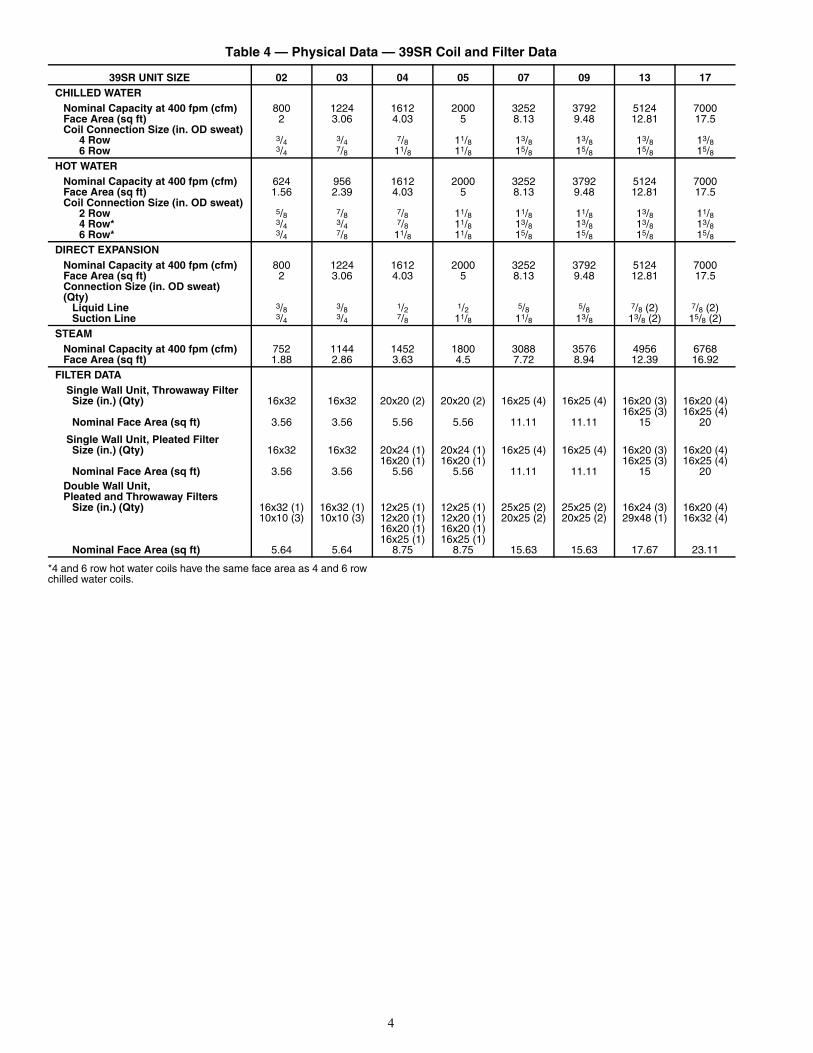
39SM UNIT SIZE
WIDTH HEIGHT DEPTH COIL SECTION
BLOWER SECTION
MOTOR START/STOP
(OPT.)RETURN DUCT SUPPLY DUCT
(BLOWER OPENING)SUPPLY CONN.
RETURN CONN. DRAIN
A B C D E F G H I J K L M N O P Q R
04 40.0 27.5 52.0 27.5 26.0 2.7 8.9 36.0 25.5 1.0 2.0 13.6 11.9 1.1 13.1 3.6 20.0 15.2
05 40.0 27.5 52.0 27.5 26.0 2.7 8.9 36.0 25.5 1.0 2.0 13.6 11.9 1.1 13.1 3.6 25.0 15.2
07 50.0 34.5 68.0 34.5 34.0 6.8 12.9 48.0 32.0 1.0 1.0 13.4 16.2 1.1 15.4 3.6 25.0 22.5
09 50.0 34.5 68.0 34.5 34.0 6.8 12.9 48.0 32.0 1.0 1.0 13.4 16.2 1.1 15.4 3.6 30.0 22.5
13 72.0 47.5 68.0 47.5 34.0 6.7 12.9 66.0 45.0 1.0 2.9 16.4 16.4 1.1 14.0 3.6 30.0 23.0
17 72.0 47.5 68.0 47.5 34.0 6.7 12.9 66.0 45.0 1.0 2.9 16.4 16.4 1.1 14.0 3.6 42.6 23.0
CW — Chilled WaterHW — Hot Waterw/o MSS — Without Motor Start/Stop Station
Fig. 6 — 39SM Unit Sizes 04-17 (Horizontal Configuration)

11
DIMENSIONS (in.)
NOTES: 1. Measurements shown in inches.2. 39SM unit shown for reference only.3. Not all components shown for clarity.4. Optional actuator not shown.5. Top and rear inlets shown. Bottom and rear inlets are also available.
39SM UNIT SIZE
LENGTH WIDTH HEIGHT DUCT WIDTH
DUCT HEIGHT
TOP CLEARANCE FILTERS
A B C D E F SIZE QTY
04,05 27.0 36.2 25.5 34.3 15.0 2.0 16 x 32 x 2 2
07,09 32.0 48.2 32.4 46.3 15.0 9.7 20 x 24 x 2 4
13,17 40.0 66.2 45.0 64.3 16.0 15.5 30 x 20 x 2 6a39-4079
Fig. 7 — 39SM Unit — Mixing Box
12
DIMENSIONS (in.)
NOTE: Measurements shown in inches.
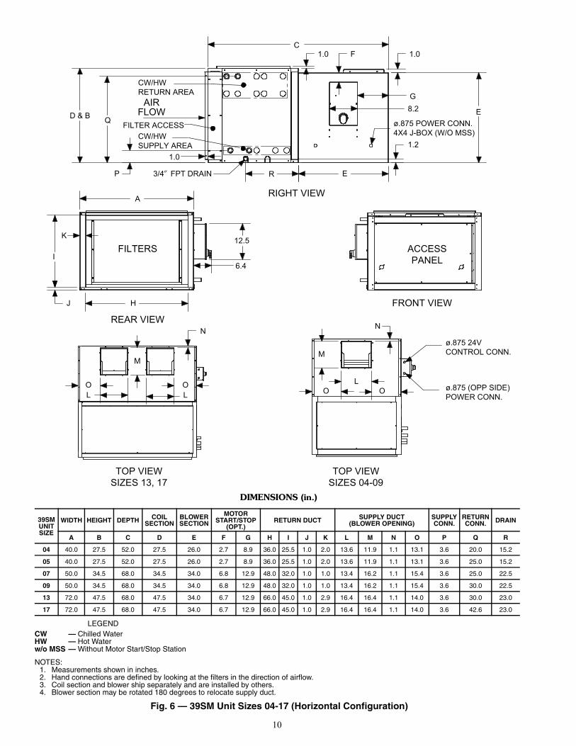
39SRUNIT SIZE A B C D E F G H J K L M N O P
02, 03 67.4 39.6 22.5 12.0 25.8 11.9 8.9 11.0 8.0 35.4 14.2 28.4 2.5 15.3 5.604, 05 72.1 48.1 28.5 12.0 34.0 14.1 13.1 11.0 8.0 35.6 18.2 35.8 5.1 17.5 6.207, 09 75.0 53.0 42.2 14.0 44.0 16.4 13.1 15.0 8.0 37.2 24.3 46.0 10.1 20.0 3.5
13 75.1 53.0 55.7 14.0 44.0 16.4 19.4 15.0 8.0 37.3 32.7 46.0 23.5 16.8 3.517 96.0 76.3 53.3 15.0 62.0 19.6 22.0 15.0 8.0 50.3 47.0 68.2 17.4 27.1 4.1
Section View "A-A"
Right View
A
4.0
A A
HORIZONTALDISCHARGE (OPT)
Front View
O
F
G
N
.875 POWERCONN. (4X4 J-BOX)
Rear View
B
M
CL
P
Pipe Chase
F
G
JK
H
D
E
4.0
4.0
a39-4068
Fig. 8 — 39SR Unit — Single Wall

13
DIMENSIONS (in.)
NOTES:1. Measurements shown in inches.2. L1 dimension is for horizontal or bottom return economizer package option.3. L2 dimension is for motorized outside air damper package option.
39SRUNIT SIZE A B C D E F G H J K L1 L2 M N O P
02, 03 70.0 42.0 30.5 12.0 26.0 11.9 8.9 10.0 6.0 33.7 17.2 14.2 28.1 8.5 16.6 7.004, 05 74.0 50.5 33.6 12.0 34.0 14.1 13.4 10.0 6.0 38.9 21.2 18.2 36.1 4.2 18.6 7.207, 09 77.4 55.5 50.9 14.0 44.0 16.4 13.1 15.0 8.0 38.0 35.1 24.3 45.9 19.9 21.2 4.8
13 77.4 55.5 60.6 14.0 44.0 16.4 18.9 15.0 8.0 38.0 48.9 32.8 45.9 29.7 18.3 4.817 96.5 76.5 64.1 14.0 62.0 19.0 22.0 15.0 8.0 51.9 48.2 46.9 65.8 24.0 27.3 5.4
F
4.0
J
G
H4.0
D
K
E
Front View
HORIZONTALDISCHARGE (OPT)
Right View
G
F
NO
Section View "A-A"
Pipe Chase
A
A A
Rear View
CL1/L2
MB
P
a39-4069
Fig. 9 — 39SR Unit — Double Wall

14
DIMENSIONS (in.)
39SR UNIT SIZE A B C D E F G02, 03 30.6 19.9 26.1 2.0 7.7 26.2 19.904, 05 39.9 18.0 25.0 1.8 9.9 40.0 22.1
B
A
F
Outdoor Air Hood
Return Air Duct
G
D
E
C
a39-4070
Fig. 10 — 39SR Unit Sizes 02-05 — Horizontal Return Economizer Package

15
DIMENSIONS (in.)
39SR UNIT SIZE A B C D E F02, 03 32.100 18.940 42.075 17.260 25.950 16.15004, 05 39.725 22.825 44.025 21.125 27.750 16.250
E F
Return Air
Outdoor Air
C
D
A
B
Fig. 11 — 39SR Unit Sizes 02-05 — Bottom Return Economizer Package

16
LEGEND
DIMENSIONS (in.)
HBREP — Horizontal Bottom Return Economizer Package
39SR UNIT SIZE A B E F G H J07, 09 13.8 44.1 35.2 34.9 15.4 16.5 48.3
13 18.8 44.1 39.0 48.6 20.1 20.0 48.317 19.0 62.9 43.4 45.1 20.1 20.0 66.1
E
H
conversion)(remove for HBREP
BarometricRelief Damper
Outdoor AirHood
G
F
B (HBREP)
A (HBREP)
J
a39-4072
Fig. 12 — 39SR Unit Sizes 07-17 — Bottom and Horizontal Return Economizer Package

17
C
D
E
F
ROTATING DAMPERASSEMBLY
HG
A
B
REAR ISOMETRIC VIEW
ACTUATOR (OPT)
FRONT ISOMETRIC VIEW
TRANSFORMER (OPT)
MOAD DIMENSIONS (in.)
39SR UNIT SIZE A B C D E F G H
02, 03 29.9 19.1 8.7 5.6 24.1 2.9 13.4 10.404, 05 37.8 23.5 14.6 5.6 25.3 6.3 17.3 13.807, 09 48.8 28.4 17.4 5.6 44.4 2.2 21.8 19.6
13 48.8 34.9 22.3 5.6 40.5 4.1 28.3 25.817 30.3 46.8 25.0 5.6 25.2 2.5 38.9 31.8
LEGENDMOAD — Motorized Outside Air Damper
Fig. 13 — 39SR Unit — Motorized Outside Air Damper
a39-4128

18
PREINSTALLATION1. Check items received against packing list.2. Do not stack unit components or accessories during stor-
age. Stacking can cause damage or deformation.3. If unit is to be stored for more than 2 weeks prior to in-
stallation, observe the following precautions:a. Choose a dry storage site that is reasonably level
and sturdy to prevent undue stress or permanentdamage to the unit structure or components. Do notstore unit on vibrating surface. Damage to station-ary bearings can occur. Set unit off ground if inheavy rain area.
b. Remove all fasteners and other small parts fromjobsite to minimize theft. Tag and store parts in asafe place until needed.
c. Cover entire unit with a tarp or plastic coverall.Extend cover under unit if stored on ground.Secure cover with adequate tiedowns or storeindoors. Be sure all coil connections have protec-tive shipping caps.
d. Monthly — Remove tarp from unit, enter fansection through access door or through fan inlet,and rotate fan and motor slowly by hand to redis-tribute the bearing grease and to prevent bearingcorrosion.
Rigging — Do not remove shipping skids or protectivecovering until unit is ready for final placement. Use slings andspreader bars as applicable to lift unit. Do not lift unit by coilconnections or headers.
Do not remove protective caps from coil piping connectionsuntil ready to connect piping.
Do not remove protective cover or grease from fan shaft un-til ready to install sheave.
Lay rigid temporary protection such as plywood walkwaysin unit to prevent damage to insulation or bottom panel duringinstallation.
Shipping Bolt and Screw Removal (36SHUnit) — On 39SH units ensure that all red shipping boltsand screws are removed and all other bolts and screws aretight. The red hold-down shipping bolts are located on bothsides of the blower/motor mounting rails and are accessiblethrough the side access panels. The red sheet metal screws arelocated on the discharge duct collar. All red bolts and screwsmust be removed for the blower assembly to be isolated fromthe cabinet. See Fig. 14.
Unit Suspension (39SH and 39SM Units) —Acceptable forms of unit suspension are shown in Fig. 15. Afield-supplied platform mount is recommended, especially forlarger unit sizes. Units can also be supported by suspending theunit from crossbeams at the joint between each unit compo-nent. Since the 39SM units lack a baserail, support membersshould also be placed along the airway length of the unit inorder to prevent buckling. Ensure that suspension rods aresecured to adequately support the unit and that the rods extendentirely through their associated fasteners.
All 39SH units have 7/8 in. knockouts in each corner of theirtop and base panels for suspension rods to pass through, locat-ed 31/2 in. in from the corners on the center line. It is recom-mended that an angle iron or Unistrut framing system be used
under the unit for support (these support pieces should extendapproximately 1 in. beyond each end of the unit width).NOTE: Locate suspension rods so they do not block accesspanels or interfere with the electrical, mechanical, or drainfunctions of unit.
Service Clearance — Provide adequate space for unitservice access (fan shaft and coil removal, filter removal, mo-tor access, damper linkage access, etc.)
Condensate Drain — To prevent excessive build-up ofcondensate in drain pan, adequate trap clearance (trap depth)must be provided beneath the unit as indicated in Fig. 16. SeeInstallation, Condensate Drain section for additional details.External Vibration Isolators — Install vibrationisolators per certified drawings, and in accordance with the jobspecifications and the instructions of the vibration isolatormanufacturer. The coil piping must be isolated or have a flexi-ble connection to avoid coil header damage because of unitmotion. A flexible connection should be installed at the fandischarge.
Figure 15 shows isolation locations for overhead suspensionof unit.
Fig. 14 — Shipping Bolt and Screw Removal
a39-4086
a39-4087

19
INSTALLATION
Condensate Drain — Install a trapped condensate drainline at unit drain connection. All 39S units have a 3/4 in. FPTcondensate drain connection.
Measure maximum design negative static pressure up-stream from the fan. Referring to Fig. 16, height “H” must beequal to or larger than negative static pressure at design operat-ing conditions. Prime enough water in trap to prevent losingseal (Differential 1). When the fan starts, Differential 2 is equalto the maximum negative static pressure.
Provide freeze-up protection as required.
Bottom Return Economizer Package (BREP)and Horizontal Bottom Return EconomizerPackage (HBREP) (39SR Unit) — Economizers areused with 39SR units for automatic sensor-controlled introduc-tion of outdoor air into the system through an electro-mechani-cally controlled damper.
To install BREP:1. Check for correct number of parts shown in Fig. 17 and
the following list.1 – Economizer assembly1 – Barometric relief hood1 – Outdoor air hood1 – Hardware bag
2. Disconnect all power to unit.3. Remove return air access panel from unit and rear access
panel(s) if applicable as shown in Fig. 18.4. To assemble the barometric relief hood, the following
will be needed. See Fig. 19.30 – Screws (type A no. 10 - 16 x 1/2 in.) 1 – 15 ft gasket (1/8 in. x 1/2 in.) 1 – 15 ft gasket (1/8 in. x 3/4 in.)a. Take hood bottom and left hood panel, putting the
flange of hood bottom to the inside of left hoodpanel and screw into place.
Fig. 16 — Condensate Drain
FAN OFF
TRAP CONDITION WHEN FAN STARTS
FAN RUNNING AND CONDENSATE DRAINING
DIFFERENTIAL 1
DRAIN NIPPLE
DIFFERENTIAL 2
COOLING COILDRAIN PAN
H
Fig. 15 — Unit Suspension
VIBRATION ISOLATORS(FIELD SUPPLIED)
CEILING – RECOMMENDEDPLATFORM MOUNT
a39-4081
CEILING – ALTERNATESUSPENSION RODS WITH NO MOUNT
a39-4088
a39-4125

20
b. Take right hood panel and screw in place likeStep a.
c. Take top rail and place flanges over left hood paneland right hood panel and secure.
d. Take top panel and do the same as Step c.e. Take 1/8 in. x 3/4 in. gasket and place around perim-
eter of front panel to seal between damper sectionand hood.
f. Take front panel and slide inside of left hood paneland right hood panel and secure.
g. Place 1/8 in. x 1/2 in. gasket on flanges on hood bot-tom, left hood panel, right hood panel, and toppanel that attach to the face of the economizerwhen installed.
h. Set barometric relief hood to the side for use later.5. To assemble the outside air hood, the following will be
needed. See Fig. 20.20 – Screws (type A no. 10 - 16 x 1/2 in.) 1 – 15 ft gasket (1/8 in. x 1/2 in.)a. Take hood bottom and left hood panel, putting the
flange of hood bottom to the inside of left hoodpanel and screw into place.
b. Take right hood panel and screw in place likeStep a.
c. Take top rail and place flanges over left hood paneland right hood panel and secure.
d. Take side rail and line up to holes in left hoodpanel and secure.
e. Repeat Step d for side rail and right hood panel.f. Take front panel and slide inside of side rails.g. Take top panel and do the same as Step c.h. Place 1/8 in. x 1/2 in. gasket on flanges on hood bot-
tom, left hood panel, right hood panel, and top railthat attach to the face of the economizer wheninstalled.
i. Set outside air hood to the side for use later.6. As shown in Fig. 21, slide economizer assembly into unit
over return opening, but DO NOT insert completely intounit. Connect low and high voltage wiring to the terminalblock and transformer per wiring diagram shown inFig. 22.
Fig. 17 — Bottom Return Economizer Package (BREP) for Sizes 07-17
a39-4089
Fig. 18 — Remove Access Panel(s) from Unit
a39-4090
Fig. 19 — Assemble Barometric Relief Hood
a39-4091
Fig. 21 — Slide Economizer Assembly into Unit
a39-4093
a39-4092
Fig. 20 — Assemble Outside Air Hood

21
Fig
. 22
— M
od
ula
tin
g G
ear
Eco
no
miz
er w
ith
Rel
ief
for
Siz
es 0
7-17
BR
EP
Un
its
NO
TE
S:
1.U
nit w
iring
sho
wn
as r
efer
ence
onl
y. C
heck
uni
t wiri
ng fo
r ac
tual
uni
t wiri
ng.
2.R
elay
s 1K
and
2K
act
uate
whe
n th
e ou
tdoo
r ai
r en
thal
py is
hig
her
than
the
retu
rn a
ir en
thal
py.
3.1S
is a
n el
ectr
onic
sw
itch
whi
ch c
lose
s w
hen
pow
ered
by
a 24
VA
C in
put.
4.Fa
ctor
y-in
stal
led
resi
stor
sho
uld
be r
emov
ed o
nly
if C
7400
diff
eren
tial e
ntha
lpy
sens
or is
add
ed.
a39-4094

22
7. To install barometric hood:For bottom return applications:Take the barometric hood and secure to economizer usingscrews as shown in Fig. 23.For horizontal return applications:a. Connect field-installed horizontal return ductwork
to duct flange. Ensure that bottom return on unit iscapped.
b. Install barometric hood over exhaust opening infield-installed ductwork. For exhaust and horizon-tal return opening sizes see duct flange dimensionsin Fig. 24.
8. Install the outside air hood. The upper flange of thehood should rest against the top of the economizer. SeeFig. 25.
9. Apply 1/8 x 1/2 in. gasketing along mounting flanges.Slide economizer assembly fully into unit and secure withthe supplied no. 10-16 x 1/2 screws. See Fig. 26.
10. Replace all panels and restore power to the unit.
Motorized Outside Air Damper — To install themotorized outside air damper:
1. Check for correct number of parts shown in Fig. 27 andthe following list.1 – Hood top2 – Hood sides2 – Filter channels1 – Filter1 – Filter access panel1 – Door panel with outside air slide1 – Adapter panel (provided if necessary)1 – Hardware bag
2. To assemble outdoor air hood (shown in Fig. 28):a. Secure the filter channels to the hood sides using
the supplied no. 10-16 x 1/2 screws.b. Place the hood sides to the inside of the side flange
of the hood top and secure with the suppliedno. 10-16 x 1/2 screws.
c. Slide the filter inside the filter channels.d. Place the filter access panel over the hood side
panels and secure with no. 10-16 x 1/2 screws.3. Adjust the position of the outside air slides on the door
panel to determine the amount of fresh air provided to theunit. See Fig. 27.
4. After the slides are in the desired position, secure theoutdoor air hood to the door panel using the providedno. 10-16 x ½ screws as shown in Fig. 28.
5. Remove the return air access panel from unit and the rearaccess panel(s) if applicable as shown in Fig. 29.
6. Locate the adapter panel (provided if necessary). Positionthe adapter panel at the top of the return air access panelunder the rooftop unit top panel. Secure the adapter panelto the rooftop unit using the supplied no. 10-16 x 1/2screws as shown in Fig. 30.
Fig. 25 — Install Outside Air Hood
a39-4097
Fig. 26 — Slide Economizer into Unit
a39-409
Fig. 23 — Install Barometric Relief Hood
BAROMETRICRELIEF HOOD
a39-4095
Fig. 24 — 39SR Unit Duct Flange Dimensions for Horizontal Return Applications
39SR UNIT SIZE
DUCT FLANGE DIMENSION (in.)A B
07,09 13.75 44.2513 18.75 44.2517 19.00 63.00
a39-4096

23
7. Center the door panel over the return-air access opening.8. Align the holes in the top and bottom of the door panel to
the holes in the rooftop unit. Secure the door panel to theunit using the provided no. 10-16 x 1/2 screws as shown inFig. 31.
Mixing Box Actuator (for 39SH and 39SM Hori-zontal Return Units Only)MIXING BOX ACTUATOR ASSEMBLY (Fig. 32 and33) — To assemble the mixing box actuator:
1. Press logic module onto actuator.2. Remove lock nut from swivel nut assembly. Place swivel
nut assembly into slot on actuator arm. Hand tighten locknut onto swivel nut assembly. Swivel nut assembly willneed to be adjusted once installed for proper actuatormotion.
3. Attach actuator arm assembly to actuator with four 1/4-in.screws. Arm may need to be repositioned once installedto ensure proper actuator motion.
Fig. 30 — Secure Adapter Panel to Unit
a39-4102
Fig. 31 — Secure Door Panel to Unit
a39-4103
Fig. 32 — Actuator Assembly
a39-4104
Fig. 27 — Motorized Outside Air Damper
a39-4099
Fig. 28 — Assemble the Outside Air Hood
a39-4100
Fig. 29 — Remove Access Panel(s) from Unit
a39-4101
24
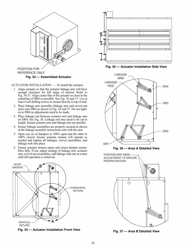
ACTUATOR INSTALLATION — To install the actuator:1. Align actuator so that the actuator linkage arm will have
enough clearance for full range of motion. Refer toFig. 34-37. Align center line of the actuator as close to thecenterline of DR4 as possible. See Fig. 36 and 37. Use atleast 4 self-drilling screws to mount directly to top of unit.
2. Place linkage arm assembly (linkage arm and swivel nutarm) onto DR4 as shown in Fig. 36 and 37. Do not tight-en to DR4 as adjustments need to be made.
3. Place linkage rod between actuator arm and linkage armon DR4. See Fig. 36. Linkage rod may need to be cut tolength. Ensure actuator arm and linkage arm are parallel.
4. Ensure linkage assemblies are properly secured as shownin the linkage assembly instructions sent with the unit.
5. Open one set of dampers to 100% open and the other to100% closed. Ensure actuator motion will operate asneeded and tighten all linkages, swivel assemblies, andlinkage rods into place.
6. Ensure actuator motion opens and closes damper assem-blies fully. If not, adjust settings of linkage arm, actuatorarm, swivel nut assemblies, and linkage rods one at a timeuntil full operation is achieved.
Fig. 35 — Actuator Installation Side View
a39-4107
Fig. 36 — Area A Detailed View
DR4
DR3
DR1
DR2
LINKAGEARM
LINKAGEROD
a39-4108
Fig. 37 — Area B Detailed View
a39-4109
Fig. 34 — Actuator Installation Front View
VERTICALRETURN
DOOR(HIDDEN)
HORIZONTALRETURN
B
Aa39-4106
Fig. 33 — Assembled Actuator
a39-4105

25
Mixing Box Air SensorMIXING BOX MIXED AIR SENSOR BRACKETASSEMBLY — To assemble the mixed air sensor bracketassembly to the mixing box, attach mixed air sensor to mixedair sensor bracket. See Fig. 38.
MIXED AND OUTSIDE AIR SENSORS INSTALLATION1. Remove access panel and filters as needed.2. Place mixed air sensor assembly in airstream as shown in
Fig. 39.3. Attach to top of unit with self drilling screws.4. Drill or knockout 1/2 in. hole into top of mixing box close
to actuator as shown in Fig. 39.5. Insert snap bushing in hole. Run wires inside unit, along
top of mixing box, between the filter rail and insulation,and attach to mixed air sensor.
6. Place enthalpy sensor, shown in Fig. 40, in location suit-able to meet manufacturer's requirements.
7. Connect all sensors to logic module per manufacturer'sinstructions.
8. Test to ensure proper function. 9. Replace all parts and tape or fill any holes or gaps made.
Mixing Box — To install mixing box:1. Insert rear return duct flanges of unit into opening of
mixing box.2. Ensure all unit flanges are inside the opening of the mix-
ing box and screw a minimum of three screws into eachof the unit’s four flanges using self-drilling screws.
3. The mixing box should now hang freely from the unit.NOTE: Hanging brackets (shipped loose), as shown inFig. 41, are recommended for 39SH and 39SM unit sizes07 and above. To install brackets, place in approximatelocation and use self-drilling screws to attach to mixingbox. Brackets are sized to allow hanging from Unistrut.Unistrut should be cut to the length one to two inchesshorter than the width of the mixing box to avoid any in-terference with the damper linkages.
4. Remove unit filters from unit before start-up.
MIXING BOX LINKAGE INSTALLATION (39SH UnitSizes 00-03) — To install the mixing box linkage assembly(sizes 00-03):
1. Check for correct number of parts:1 – Linkage rod2 – Linkage arms2 – Swivel joints
NOTE: A 7/16 in. box end wrench and/or socket will beneeded for linkage installation.
2. Attach actuator (optional item) to unit with actuatormounting hardware included with actuator. Actuatorshould be mounted on damper rod 1 (DR1) as shown inFig. 42.
3. Orientate actuator to avoid interference with linkageassembly.
4. Ensure dampers are fully closed or open depending onapplication, and secure actuator to shaft. Actuator shouldopen and close dampers fully. Adjust actuator as needed.
Fig. 39 — Mixed Air Sensor Installation
MIXEDAIR SENSORASSEMBLY
HOLELOCATION
a39-4111Fig. 41 — Installing Mixing Box
MIXINGBOX
HANGINGBRACKETS(1 in. DIA.) UNIT FILTER
ACCESS DOOR
39SHUNIT
a39-4113
Fig. 38 — Mixed Air Sensor Bracket
a39-4110
Fig. 40 — Enthalpy Sensor
a39-4112

26
5. Place a linkage arm onto DR1 and DR2. See Fig. 42 and43 for proper positioning. Ensure that swivel joints arefully extended to the end of the linkage arm and tighten.
6. Insert linkage rod into swivel joints and tighten. Linkagerod may need to be cut down to size. Linkage armsshould be parallel.
7. Ensure one set of dampers are fully open and the otherfully closed. Adjust linkage assembly to allow travelwithout interference and tighten to DR1 and DR2.
8. The actuator should now be able to power the dampersfully open and fully closed without interference. Adjustlinkage assemblies as needed.
MIXING BOX LINKAGE INSTALLATION (Sizes 04-17) — To install the mixing box linkage assembly (sizes04-17):
1. Check for correct number of parts:3 – Linkage rods6 – Linkage arms6 – Swivel joints
NOTE: A 7/16 in. box end wrench and/or socket will beneeded for linkage installation.
2. An alternate field-supplied actuator may be installeddirectly on the damper shaft if required. If a factory-supplied actuator is ordered for the mixing box, refer toMixing Box Actuator section on page 23.
3. Orientate actuator to avoid interference with linkageassembly. Refer to Fig. 44 and 45.
4. Ensure dampers are fully closed or open depending onapplication, and secure actuator to shaft. Actuator shouldopen and close dampers fully. Adjust actuator as needed.
5. Place a linkage arm onto DR3 and DR2. See Fig. 46 and47. for proper positioning. Ensure that swivel joints arefully extended to the end of the linkage arm and tighten.
6. Insert linkage rod into swivel joints and tighten. Linkagerod may need to be cut down to size. Linkage armsshould be parallel. Assembly should still be loose ondamper rods. This will be linkage assembly no. 1.
7. Place linkage arm onto DR1 and DR2. Ensure swiveljoints are fully extended to the end of the linkage arm andtighten.
8. Insert linkage rod into swivel joints and tighten. Linkagerod may need to be cut down to size. Linkage armsshould be parallel.
9. Ensure dampers are fully open or closed and tighten link-age arms to damper rods. Linkage assembly should beable to open and close dampers fully without interference.Adjust accordingly.
10. Place linkage arm onto DR3 and DR4. Ensure swiveljoints are fully extended to the end of the linkage arm andtighten.
11. Insert linkage rod into swivel joints and tighten. Linkagerod may need to be cut down to size. Linkage armsshould be parallel.
12. Ensure dampers are fully open or closed and tighten link-age arms to damper rods. Linkage assembly should beable to open and close dampers fully without interference.Adjust accordingly.
13. Ensure one set of dampers is fully open and the other ful-ly closed. Adjust linkage assembly no. 1 to allow travelwithout interference and tighten to DR2 and DR3.
14. The actuator should now be able to power the dampersfully open and fully closed without interference. Adjustlinkage assemblies as need.
Fig. 44 — Linkage Assembly Front View (Sizes 04-17)
a39-4116
Fig. 45 — Linkage Assembly Side View(Sizes 04-17)
a39-4117
Fig. 42 — Linkage Assembly Front View(Sizes 00-03)
VERTICALRETURN
HORIZONTALRETURN
ACTUATOR(OPTIONAL)
LINKAGEARM
DR2
DR1
LINKAGE ROD
a39-4114
Fig. 43 — Linkage Assembly Side View(Sizes 00-03)
a39-4115

27
Install Sheaves on Motor and Fan Shafts —Factory-supplied drives are prealigned and tensioned, however,Carrier recommends that the belt tension and alignment bechecked before starting the unit. Always check the drive align-ment after adjusting belt tension.
When field installing or replacing sheaves, install sheaveson fan shaft and motor shaft for minimum overhang. (SeeFig. 48.) Use care when mounting sheave on fan shaft; toomuch force may damage bearing. Remove rust-preventativecoating or oil from shaft. Make sure shaft is clean and free ofburrs. Add grease or lubricant to bore of sheave beforeinstalling.
ALIGNMENT — Make sure that fan shafts and motor shaftsare parallel and level. The most common causes of mis-alignment are nonparallel shafts and improperly locatedsheaves. Where shafts are not parallel, belts on one side aredrawn tighter and pull more than their share of the load. As aresult, these belts wear out faster, requiring the entire set to bereplaced before it has given maximum service. If misalignmentis in the sheave, belts will enter and leave the grooves at anangle, causing excessive belt cover and sheave wear.
1. Shaft alignment can be checked by measuring thedistance between the shafts at 3 or more locations. If thedistances are equal, then the shafts will be parallel.
2. Check alignment of sheaves:Fixed sheaves — To check the location of the fixedsheaves on the shafts, a straightedge or a piece of stringcan be used. If the sheaves are properly lined up the stringwill touch them at the points indicated by the arrows inFig. 49.Adjustable sheave — To check the location of adjustablesheave on shaft, make sure that the centerlines of bothsheaves are in line and parallel with the bearing supportchannel. See Fig. 49. Adjustable pitch drives are installedon the motor shaft.
3. Rotating each sheave a half revolution will determinewhether the sheave is wobbly or the drive shaft is bent.Correct any misalignment.
CAUTION
With adjustable sheave, do not exceed maximum fan rpm.
Fig. 48 — Determining Sheave-Shaft Overhang
a39-1733
Fig. 46 — Area A Detailed View
DR4
ACTUATOR(OPTIONAL)
DR3
DR1
DR2
LINKAGEARM
LINKAGEROD
a39-4118
Fig. 47 — Area B Detailed View
a39-4119

28
4. With sheaves aligned, tighten cap screws evenly andprogressively.NOTE: There should be a 1/8-in. to 1/4-in. gap betweenthe mating part hub and the bushing flange. If gap isclosed, the bushing is probably the wrong size.
5. With taper-lock bushed hubs, be sure the bushing boltsare tightened evenly to prevent side-to-side pulley wob-ble. Check by rotating sheaves and rechecking sheavealignment.
Install V-Belts — When installing or replacing belts, al-ways use a complete set of new belts. Mixing old and new beltswill result in the premature wear or breakage of the newerbelts.
1. Always adjust the motor position so that V-belts can beinstalled without stretching over grooves. Forcing beltscan result in uneven stretching and a mismatched set ofbelts.
2. Do not allow belt to bottom out in sheave.3. Tighten belts by turning motor-adjusting jackscrews.
Turn each jackscrew an equal number of turns.4. Equalize belt slack so that it is on the same side of belt for
all belts. Failure to do so may result in uneven beltstretching.
5. Tension new drives at the maximum deflection forcerecommended (Fig. 50).
6. To determine correct belt tension, use the deflectionformula given below and the tension data from Fig. 50 asfollows:EXAMPLE:Given
Belt Span 16 in.Belt Cross-Section A, Super BeltSmall Sheave Pitch Diameter 5 in.
Solution1. From Fig. 50 find that deflection force for type A, super
belt with 5-in. small sheave pitch diameter is 4 to 51/2 lb.2.
3. Increase or decrease belt tension until force required for1/4-in. deflection is 51/2 lb.Check belt tension at least twice during first operatingday. Readjust as required to maintain belt tension withinthe recommended range.
With correct belt tension, belts may slip and squealmomentarily on start up. This slippage is normal and disap-pears after unit reaches operating speed. Excessive belt tensionshortens belt life and may cause bearing and shaft damage.
After run-in, set belt tension at lowest tension at which beltswill not slip during operation.
Deflection =(Belt Span)
64
Deflection = 1664
PD — Pitch Diameter, inches
Fig. 50 — Fan Belt Tension Data
BELTCROSS
SECTION
SMALL SHEAVE
PD RANGE (in.)
DEFLECTION FORCE — LBSuper Belts
Notch Belts
Steel Cable Belts
Min Max Min Max Min Max
A3.0- 3.6 3 41/4 37/8 51/2 3 43.8- 4.8 31/2 5 41/2 61/4 33/4 43/45.0- 7.0 4 51/2 5 67/8 41/4 51/4
B3.4- 4.2 4 51/2 53/4 8 41/2 51/24.4- 5.6 51/8 71/8 61/2 91/8 53/4 71/45.8- 8.6 63/8 83/4 73/8 101/8 7 83/4
C7.0- 9.4 111/4 143/8 133/4 177/8 111/4 149.6-16.0 141/8 181/2 151/4 201/4 141/4 173/4
3V2.65-3.65 31/2 5 37/8 51/2 — —4.12-6.90 43/4 67/8 51/4 77/8 — —
5V4.40-6.70 — — 10 15 — —7.1-10.9 101/2 153/4 127/8 183/4 — —
11.8-16.0 13 191/2 15 22 — —
8V12.5-17.0 27 401/2 — — — —18.0-22.4 30 45 — — — —
a39-1
Fig. 49 — Sheave Alignment

29
Water and Steam Coil Piping RecommendationsGENERAL — Use straps around the coil casing to lift andplace the coil.
Piping practices are outlined in the Carrier System DesignManual, Part 3, Piping Design. WATER COILS — Typically, coils are piped by connectingthe supply at the bottom and the return at the top. This is not al-ways the case, especially if the coil hand has been changed inthe field. Coils must be piped for counterflow; otherwise, a ca-pacity reduction of 5% for each coil row will result. To ensurecounterflow, chilled water coils are piped so that the coldestwater meets the coldest air. Hot water coils are piped so that thewarmest water meets the warmest air. Some 39S coils have 3connections on either side of the coil (for a total of 6 connec-tions). In these cases, the middle connection is used as the re-
turn connection. See Fig. 51.STEAM COILS — Position the steam supply connection atthe top of the coil, and the return (condensate) connection at thebottom.
Figure 52 illustrates the normal piping components and thesuggested locations for high, medium, or low-pressure steamcoils. The low-pressure application (zero to 15 psig) candispense with the ¼-in. petcock for continuous venting locatedabove the vacuum breaker (check valve).
Note the horizontal location of the 15-degree check valve,and the orientation of the gate/pivot. This valve is intended torelieve any vacuum forming in the condensate outlet of acondensing steam coil, and to seal this port when steampressure is again supplied to the coil. It must not be installed inany other position, and should not be used in the supply line.
For coils used in tempering service, or to preheat outside air,install an immersion thermostat in the condensate line ahead ofthe trap. This will shut down the supply fan and close the out-door damper whenever the condensate falls to a predeterminedpoint, perhaps 120 F.NOTE: Do NOT use an immersion thermostat to override aduct thermostat and open the steam supply valve.
For vacuum return systems, the vacuum breaking checkvalve would be piped into the condensate line between the trapand the gate valve instead of open to the atmosphere.
Figure 53 illustrates the typical piping at the end of everysteam supply main. Omitting this causes many field problemsand failed coils.
Figure 54 shows the typical field piping of multiple coils.Use this only if the coils are the same size and have the samepressure drop. If this is not the case, an individual trap must beprovided for each coil.
Figure 55 shows a multiple coil arrangement applied to agravity return, including the open air relief to the atmosphere,which DOES NOT replace the vacuum breakers.
Figure 56 illustrates the basic condensate lift piping.
CAUTION
To prevent damage to the coil or coil headers: Do not usethe headers to lift the coil. Support the piping and coil con-nections independently. Do not use the coil connections tosupport piping. When tightening coil connections, use abackup wrench on the nozzles.
53
NOTES:1. Flange or union is located to facilitate coil removal.2. Flash trap may be used if pressure differential between steam
and condensate return exceeds 5 psi.3. When a bypass with control is required.4. Dirt leg may be replaced with a strainer. If so, tee on drop can
be replaced by a reducing ell.5. The petcock is not necessary with a bucket trap or any trap
which has provision for passing air. The great majority of highor medium pressure returns end in hot wells or deaeratorswhich vent the air.
Fig. 52 — Low, Medium or High Pressure Coil Piping
a39-4129
Fig. 51 — Water Coil Connection
LEGENDCW — Chilled WaterHW — Hot WaterLH — Left HandRH — Right Hand
a39-4126

30
NOTES:1. Flange or union is located to facilitate coil removal.2. To prevent water hammer, drain coil before admitting steam.3. Do not exceed one foot of lift between trap discharge and
return main for each pound of pressure differential.4. Do not use this arrangement for units handling outside air.
Fig. 56 — Condensate Lift to Overhead Return
a39-2365tf.tif
3
NOTES:1. Flange or union is located to facilitate coil removal.2. When control valve is omitted on multiple coils in parallel air
flow.3. When a bypass with control is required.4. Coils with different pressure drops require individual traps. This
is often caused by varying air velocities across the coil bank.
Fig. 55 — Multiple Coil Low PressurePiping Gravity Return
a39-4131
NOTES:1. A bypass is necessary around trap and valves when continu-
ous operation is necessary.2. Bypass to be the same size as trap orifice but never less than
1/2 inch.
Fig. 53 — Dripping Steam Supply toCondensate Return
a39-2362tf.tif
3
NOTES:1. Flange or union is located to facilitate coil removal.2. When a bypass with control is required.3. Flash trap can be used if pressure differential between supply
and condensate return exceeds 5 psi.4. Coils with different pressure drops require individual traps. This
is often caused by varying air velocities across the coil bank.5. Dirt leg may be replaced with a strainer. If so, tee on drop can
be replaced by a reducing ell.6. The petcock is not necessary with a bucket trap or any trap
which has provision for passing air. The great majority of highpressure return mains terminate in hot wells or deaeratorswhich vent the air.
Fig. 54 — Multiple Coil High Pressure Piping
a39-4130

31
Following the piping diagrams in Fig. 52-56, make all con-nections while observing the following precautions:• Install a drip line and trap on the pressure side of the
inlet control valve. Connect the drip line to the returnline downstream of the return line trap.
• To prevent scale or foreign matter from entering the con-trol valve and coil, install a 3/32-in. mesh strainer in thesteam supply line upstream from the control valve.
• Provide air vents for the coils to eliminate noncondens-able gases.
• Select a control valve according to the steam load, notthe coils supply connection size. Do not use an oversizedcontrol valve.
• Do not use bushings that reduce the size of the headerreturn connection. The return connection should be thesame size as the return line and reduced only at thedownstream trap.
• To lift condensate above the coil return line into over-head steam mains, or pressurized mains, install a pumpand receiver between the condensate trap and thepressurized main. Do not try to lift condensate withmodulating or on-and-off steam control valves. Use only15-degree check valves, as they open with a lower waterhead. Do not use 45-degree or vertical-lift check valves.
• Use float and thermostatic traps. Select the trap sizeaccording to the pressure difference between the steamsupply main and the return main.
• Load variations can be caused by uneven inlet air distri-bution or temperature stratification.
• Drain condensate out of coils completely at the end ofthe heating season to prevent the formation of acid.
Coil Freeze-Up ProtectionWATER COILS — If a chilled water coil is applied with out-side air, provisions must be made to prevent coil freeze-up.Install a coil freeze-up thermostat to shut down the system ifany air temperature below 36 F is encountered entering thewater coil. Follow thermostat manufacturer’s instructions.
When a water coil is applied downstream of a direct-expansion (DX) coil, a freeze-up thermostat must be installedbetween the DX and water coil and electrically interlocked toturn off the cooling to prevent freeze-up of the water coil.
For outdoor-air application where intermittent chilled watercoil operation is possible, one of the following steps should betaken:• Install an auxiliary blower heater in cabinet to maintain
above-freezing temperature around coil while unit isshut down.
• Drain coils and fill with an ethylene glycol solution suit-able for the expected cold weather operation. Shut downthe system and drain coils. See Service section, WinterShutdown.
STEAM COILS — When used for preheating outdoor air inpressure or vacuum systems, an immersion thermostat to con-trol outdoor-air damper and fan motor is recommended. Thiscontrol is actuated when steam supply fails or condensate tem-perature drops below an established level, such as 120 to 150 F.A vacuum breaker should also be used to equalize coil pressurewith the atmosphere when steam supply throttles close. Steamshould not be modulated when outdoor air is below 40 F.
On low-pressure and vacuum steam-heating systems, thethermostat may be replaced by a condensate drain with a ther-mal element. This element opens and drains the coil when con-densate temperature drops below 165 F. Note that condensatedrains are limited to 5 psig pressure.INNER DISTRIBUTING TUBE STEAM COILS — Theinner distributing tube (IDT) steam coil used in the 39S air-handling units has an inner tube pierced to facilitate the distri-bution of the steam along the tube's length. The outer tubes are
expanded into plate fins. The completed assembly includes thesupply and condensate header and side casings which are builtto slant the fin/tube bundle back toward the condensate header.The slanting of the assembly ensures that condensate will flowtoward the drains. This condensate must be removed throughthe return piping to prevent premature failure of the coil. Thefin/tube bundle is slanted vertically for horizontal airflow coils,and horizontally for vertical airflow coils.IDT Steam Coil Piping — The following piping guidelineswill contribute to efficient coil operation and long coil life:
1. Use full size coil outlets and return piping to the steamtrap. Do not bush return outlet to the coil. Run full size tothe trap, reduce at the trap.
2. Use float and thermostatic (F & T) traps only for conden-sate removal. Trap size selection should be based on thedifference in pressure between the steam supply main andthe condensate return main. It is good practice to select atrap with 3 times the condensate rating of the coil towhich it is connected.
3. Use thermostatic traps for venting only.4. Use only 1/2-in., 15-degree swing check valves installed
horizontally, piped open to atmosphere, and located atleast 12 in. above the condensate outlet. Do not use45-degree, vertical lift and ring check valves.
5. The supply valve must be sized for the maximum antici-pated steam load.
6. Do not drip steam mains into coil sections. Drip them onthe pressure side of the control valve and trap them intothe return main beyond the trap for the coil.
7. Do not use a single trap for two or more coils installed inseries. Where two or more coils are installed in a singlebank, in parallel, the use of a single trap is permissible,but only if the load on each coil is equal. Where loads inthe same coil bank vary, best practice is to use a separatetrap for each coil.Variation in load on different coils in the same bank maybe caused by several factors. Two of the most commonare uneven airflow distribution across the coil and stratifi-cation of inlet air across the coil.
8. Do not try to lift condensate above the coil return into anoverhead main, or drain into a main under pressure with amodulating or on/off steam control valves. A pumpand receiver should be installed between the coil conden-sate traps and overhead mains and return mains underpressure.
9. Use a strainer (3/32-in. mesh) on the steam supply side,as shown in the piping diagrams, to avoid collection ofscale or other foreign matter in the inner tube distributingorifices.
NOTE: IDT coils must be installed with the tubes drainingtoward the header end of the coil. The IDT steam coils arepitched toward the header end as installed in the unit.10. Ensure the AHU (air-handling unit) is installed level to
maintain the inherent slope. Also ensure the unit is in-stalled high enough to allow the piping to be installed cor-rectly, especially the traps which require long drip legs.
11. Do not fail to provide all coils with the proper air vents toeliminate noncondensable gasses.
12. Do not support steam piping from the coil units. Bothmains and coil sections should be supported separately.
IDT Steam Coil Installation — Refer to drawings to positionthe coils properly with regard to the location of the supply andreturn connections. Ensure that the IDT coil is pitched with thetubes draining toward the header. The AHUs provide propercoil pitch when the AHU is installed level.
Refer to schematic piping diagrams and piping connectionnotes for the recommended piping methods.

32
Refrigerant Piping, Direct-Expansion (DX)Coils — Direct-expansion coils are divided into 1 or 2 splitsdepending upon the unit size and coil circuiting. Each split re-quires its own distributor nozzle, expansion valve, and suctionpiping. Suction connections are on the air entering side whenthe coil is properly installed. Matching distributor connectionsfor each coil split are on the air leaving side. See unit label orcertified drawing to assure connection to matching suction andliquid connections.
The lower split of face split coils should be first on, last off.Row split coils utilize special intertwined circuits; either
split of these row split coils can be first on, last off.
SUCTION PIPING — Connect suction piping as shown inFig. 57 for face split coil.
Suction line from coil connection to end of the 15-diameter-long riser should be same tube size as coil connection to ensureproper refrigerant velocity.
Refer to Carrier System Design Manual, Part 3, and size re-maining suction line to compressor for a pressure drop equiva-lent to 2.0 F. This will provide a total suction line header pres-sure drop equivalent to approximately 2.5 F. Refer to Fig. 58for piping risers to the compressor.
To minimize the possibility of flooded starts and compres-sor damage during prolonged light load operation, install anaccumulator in the suction line or a solenoid in the liquid lineof last-on, first off split in row-split applications.
EXPANSION VALVE PIPING — Distributor nozzles andexpansion valves sized for acceptable performance for a rangeof conditions are factory supplied. Use the AHU (air-handlingunit) selection program in the electronic catalog to select opti-mal nozzle sizes.
Circuiting selection should result in a circuit loading of 0.8to 2.0 tons per circuit at design load. Circuit loading must beevaluated at minimum load to ensure that it does not dropbelow 0.6 tons per circuit. Solenoid valves may be used, if nec-essary, to shut off the refrigerant supply to individual expansionvalves to maintain adequate coil circuit loading.
Compressor minimum unloading and TXV quantity is nec-essary to determine minimum tonnage per circuit.
Minimum Unloading Equation:
Example:Condensing Unit: 38ARS012Minimum Unloading:33%Coil: 6 row, 11 FPI, Half CircuitCoil Tons per Circuit:1.68Total TXVs: 2
In the first example we will determine the tons per circuitwhen both TXVs are active and the compressor is unloaded toits minimum of 33%.
= .55 tons per circuit at minimum unloadingUNACCEPTABLE
If we install a liquid line solenoid valve before one of theTXVs and close it so that only one TXV is active when thecompressor is unloaded to its minimum of 33%, we see thefollowing:
= 1.10 tons per circuit at minimum unloading ACCEPTABLE
CAUTION
Direct-expansion coils are shipped pressurized with drynitrogen. Release pressure from each coil split throughvalves in protective caps before removing caps.
Do not leave piping open to the atmosphere unnecessar-ily. Water and water vapor are detrimental to the refrigerantsystem. Until the piping is complete, recap the system andcharge with nitrogen at the end of each workday. Clean allpiping connections before soldering joints.Failure to follow these procedures could result in personalinjury or equipment damage.
(Tons per Circuit) x (Minimum Unloading)x (Total no. of TXVs)no. of TXVs Active
=
(1.68 Tons per Circuit) x (33% Minimum Unloading)x (2 TXVs)
2 TXVs Active
= (1.68) x (.33) x (2)2
=
(1.68 Tons per Circuit) x (33% Minimum Unloading)x (2 TXVs)
1 TXV Active
= (1.68) x (.33) x (2)1
Fig. 58 — Suction Line Riser Piping
a39-516tf.tif
TXV — Thermostatic Expansion Valve
Fig. 57 — Face Split Coil Suction Line Piping
a39-139.tif

33
There are three different options to control tons per circuitwhen using an unloading compressor. The first is to usedrop solenoid valve control as illustrated above and let thesuction cutoff unloaders “ride” with the load. The second is touse drop solenoid valve control as illustrated above withelectric unloaders and let the control algorithm determine thecombination of solenoid valves and unloaders to limit tons percircuit to acceptable limits. The third is to limit the minimumamount of unloading so that tons per circuit is within accept-able limits.
Electric Heaters — Electric heaters may be factory-installed or factory-supplied for field installation.
Motor Start/Stop Stations
All field-installed wiring, including the electrical ground,MUST comply with the National Electrical Code (NEC) aswell as applicable local codes. In addition, all field wiring mustconform to the Class II temperature limitations described in theNEC.
Refer to Fig. 59 and 60 for optional factory-installed motorstart/stop station wiring diagrams.
WARNING
To avoid possible injury or death due to electrical shock,open the power supply disconnect switch and secure it inan open position during installation.
CAUTION
Use only copper conductors for field-installed electricalwiring. Unit terminals are not designed to accept othertypes of conductors.
Fig. 59 — Sinlge-Phase Motor Start/Stop Station Wiring Diagram
LEGENDGND — GroundTB — Terminal Block
a39-4124
Fig. 60 — 3-Phase Motor Start/Stop Station Wiring Diagram
a39-4123
LEGENDGND — GroundTB — Terminal Block

34
START-UP
Check List — Make a walkway inside unit components toprotect insulation. Remove all construction debris from unitinterior. Remove walkway before starting unit.FILTERS — Install unit filters in all filter sections.FANS
1. Check lubrication of fan, motor bearings, and linkages.a. Note that bearings are shipped completely full of
grease for corrosion protection and may run warmtemporarily on start-up until excess grease hasdischarged.
b. Hand-operate all damper linkages to check forfreedom of movement.
2. Check tightness of bearing setscrews or locking collars.Also, check tightness of setscrews on fan wheels andsheaves.
3. Check tightness of fan shaft bearing mounting.4. Recheck sheave alignment and belt tension. (Refer to
Fig. 49 and 50.)5. Hand turn fan to make certain fan wheel does not rub in
housing.6. Check fan speed with a strobe-type tachometer or use the
following formula: Obtain the motor rpm from the fanmotor nameplate and read sheave pitch diameters markedon the fan and motor pulleys, or estimate the pitch diame-ters by using the pulley outside diameters.Then:
Example:Actual Approximate
Nameplate MotorRpm = 1760 1760
Mtr Sheave PitchDiameter = 8.9 in. 9.0 (OD)
Fan Sheave PitchDiameter = 12.4 in. 12.5 (OD)
Fan Rpm = 1760 x 8.9 1760 x 9= 12.4 12.5= 1263 Rpm 1267 Rpm
Refer to the product data catalog for maximum allowablefan speeds for standard wheels. Excessive fan speed mayresult in condensate carryover from cooling coil or fanmotor overload and wheel failure.
7. Check direction of rotation (see Fig. 61). Arrow on driveside of fan housing indicates correct direction of rotation.
8. Check vibration. If excessive vibration occurs, check forthe following:a. Variable sheave (if air balance of system has been
accomplished: replace sheave with fixed sheavefor continuous application).
b. Drive misalignment.c. Mismatched, worn or loose belts.d. Wheel or sheaves loose on shaft.e. Loose bearings.f. Loose mounting bolts.g. Motor out of balance.h. Sheaves eccentric or out of balance.i. Vibration isolators improperly adjusted.j. Out-of-balance or corroded wheel (rebalance or
replace if necessary).k. Accumulation of material on wheel (remove
excess material).
SERVICE
General1. Place a suitable walkway to protect floor insulation
whenever entering the fan section.2. Review Safety Considerations at beginning of these in-
structions. Good safety habits are important tools whenperforming service procedures.
3. To make speed measurements, use a strobe-style tachom-eter or calculate per Step 6 of Start-Up, Check List.
Fan Motor Replacement1. Shut off motor power.2. Disconnect and tag power wires at motor terminals.3. Loosen motor brace-to-mounting-rail attaching bolts.
Loosen belt tensioning bolts to adjust the motor positionso V-belts can be removed without stretching overgrooves.
4. Mark belt as to position. Remove and set aside belts.5. Remove motor to motor bracket holddown bolts.6. Remove motor pulley and set aside.7. Remove motor.8. Install new motor. Reassemble by reversing Steps 1-6. Be
sure to reinstall multiple belts in their original position.Use a complete new set if required. Do not stretch beltsover sheaves. Review the sections on motor and sheaveinstallation, sheave alignment and belt tensioning dis-cussed previously (Fig. 48-50).
9. Reconnect motor leads and restore power. Check fan forproper rotation as described in Start-Up, Check List.
Coil CleaningDETERGENT — Spray mild detergent solution on coils withgarden-type sprayer. Rinse with fresh water. Check to ensurecondensate line is free. Excess water from cleaning may floodunit if condensate line is plugged.
Winter Shutdown (Chilled Water Coil Only)ANTIFREEZE METHODS OF COIL PROTECTION
1. Close coil water supply and return valves.2. Drain coil as follows:
Method I — ‘Break’ flange of coupling at each headerlocation. Separate flange or coupling connection to facili-tate coil draining.Method II — Open both valves to auxiliary drain piping.
Fan Rpm =
Motor Rpm x Motor Sheave Pitch Diameter (in.)
Fan Sheave Pitch Diameter (in.)
Fig. 61 — Fan Wheel Rotation
a39-777.tif

35
3. After coil is drained:Method I — Connect line with a service valve and unionfrom upper nozzle to an antifreeze reservoir. Connect aself-priming reversible pump between the low headerconnection and the reservoir.Method II — Make connection to auxiliary drain valves.
4. Fill reservoir with any inhibited antifreeze acceptable tocode and underwriter authority.
5. Open service valve and circulate solution for 15 minutes;then check its strength.
6. If solution is too weak, add more antifreeze until desiredstrength is reached, then circulate solution through coilfor 15 minutes or until concentration is satisfactory.
7. Remove upper line from reservoir to reversible pump.Drain coil to reservoir and then close service valve.
8. Break union and remove reservoir and its lines.9. Leave coil flanges or coupling open and auxiliary drain
valves open until spring.AIR DRYING METHOD OF COIL PROTECTION (Unitand coil must be level for this method.)
1. Close coil water supply and return main valves.2. Drain coil as described in procedures for Antifreeze
Methods of Coil Protection.3. Connect air supply or air blower to inlet header connec-
tion and close its drain connection.4. Circulate air and check for air dryness by holding mirror
in front of open vent in outlet header drain connection.Mirror will fog if water is still present.
5. Allow coil to stand for a few minutes; repeat Step 4 untilcoil is dry.
PIPING — Direct expansion, chilled water, and hot watercoils should always be piped for counterflow. (Fluid shouldenter the coil at the leaving-air side.) Steam coils must have thecondensate connection at bottom of coil.
To determine intervals for cleaning coils in contaminated airoperations, pressure taps should be installed across the coilsand checked periodically. Abnormal air pressure drop will indi-cate a need for cleaning the coils.Annual maintenance should include:
1. Clean the line strainers.2. Blow down the dirt leg.3. Clean and check operation of steam traps.4. Check operation of control valves. 5. Check the operation of check valves to prevent conden-
sate flowback.6. Check operation of thermostatic air vents, if used. A float
and thermostatic trap will contain a thermostatic air vent.When the bellows is ruptured, it will fail closed.
7. Check operation of vacuum breakers.8. Check operation of the thermal protection devices used
for freeze-up protection.9. Steam or condensate should not be allowed to remain in
the coil during the off season.This will prevent the forma-tion and build up of acids.
There are additional precautions and control strategies, asfound in various catalogues and in the ASHRAE FundamentalsHandbook and in the Carrier System Design Guide — PipingSection, when the entering-air temperature to the coil falls be-low 35 F. These conditions occur when IDT coils are used forpre-heat and/or face and bypass applications.Freeze up protection:
1. Use a strainer in the supply line and the dirt leg ahead ofthe trap.
2. Use a vacuum breaker in the return.3. Do not use overhead returns from the coil. A floodback
can occur.4. An immersion thermostat to control outdoor-air dampers
and the fan motor is recommended. This control is acti-vated when the steam supply fails or the condensatetemperature drops below a predetermined temperature,usually 120 F.
5. On low pressure and vacuum systems, the immersionthermostat may be replaced by a condensate drain with athermal element. This element opens and drains the coilwhen the condensate temperature drops below 165 F.Note the thermal condensate drain is limited to 5 psigpressure. At greater coil pressures they will not open.
In spite of the precautions listed above, a coil may stillfreeze up. An oversize capacity coil, at partial load, with amodulating steam control valve will occasionally freeze.Freezing occurs in the 20 F to 35 F range of entering-airtemperatures. A better installation would be an undersize coil,with an on/off control valve with thermostatic control in theoutside air, set at 35 F air temperature, installed downstream ofthe first coil; or setting the minimum steam pressure at 5 psig.
FiltersFILTER SECTIONS — Open or remove filter panel to re-place old filter with a new filter. See physical data tables for fil-ter data.
LubricationMOTORS — Lubricate in accordance with nameplate at-tached to motor or with manufacturer’s recommendationsincluded with motor.BEARINGSFan Bearings — Lubricate fan bearings in accordance withmanufacturer’s recommendations included with blower.

Manufacturer reserves the right to discontinue, or change at any time, specifications or designs without notice and without incurring obligations.Catalog No. 04-53390006-01 Printed in U.S.A. Form 39S-2SI Pg 36 7-08 Replaces: 39S-1SI
Copyright 2008 Carrier Corporation
SERVICE TRAINING
Packaged Service Training programs are an excellent way to increase your knowledge of theequipment discussed in this manual, including:
• Unit Familiarization • Maintenance• Installation Overview • Operating Sequence
A large selection of product, theory, and skills programs are available, using popular video-basedformats and materials. All include video and/or slides, plus companion book.Classroom Service Training which includes “hands-on” experience with the products in our labs canmean increased confidence that really pays dividends in faster troubleshooting and fewer callbacks.Course descriptions and schedules are in our catalog.
CALL FOR FREE CATALOG 1-800-644-5544[ ] Packaged Service Training [ ] Classroom Service Training