Embed Size (px)
Citation preview
09/17/2014 202-‐A35-‐2272-‐INST
Installation Manual v1.0: P/N 202-A35-2272
Aurora 3000/5000 Compound Turbo Kit 2003-2007 Dodge Cummins 5.9
Please read all instructions before installation.
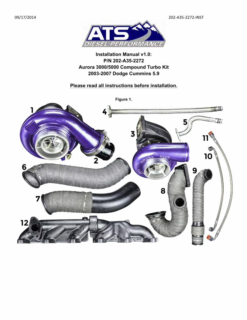
Figure 1.

09/17/2014 202-‐A35-‐2272-‐INST Figure 2.
Figure 3.

09/17/2014 202-‐A35-‐2272-‐INST Figure 4.
1. Install the ATS manifold (Item 1, Figure 1) using the 10 bolts (Item 17, Figure 3), lock washers (Item 11, Figure 3), and flat washers (Item 15, Figure 3) leaving the top center bolts out. (We’ll come back to these two bolts in a few steps.) When bolting the manifold in place be sure to set each of the six gaskets (Item 10, Figure 3) in place before tightening the manifold bolts. (See figure 5) Manifold to head bolt torque is 32ft-lbs.
Figure 5.
2. Bolt the ATS Aurora 3000 (Item 3, Figure 1) to the manifold. Using two of the supplied studs (Item 12, Figure 3) install them in the T3 flange closest to the engine. Place the T3 gasket (Item 2, Figure 3) in position and install the Aurora 3000 using the two supplied bolts (Item 8, Figure 3) and four nuts (Item 16, Figure 3) (See figure 6) Turbo to manifold torque is 32ft-lbs.

09/17/2014 202-‐A35-‐2272-‐INST Figure 6.
3. Install the oil feed line (Item 11, Figure 1) for the Aurora 3000 (See figure 7) Oil supply line fitting torque is 18ft-lbs. Oil supply fitting torque is 27ft-lbs
Figure 7.
4. Install the oil drain (Item 5, Figure 1) and gasket (Item 3, Figure 3) (See figure 8) Oil drain tube bolt torque is 18ft-lbs.
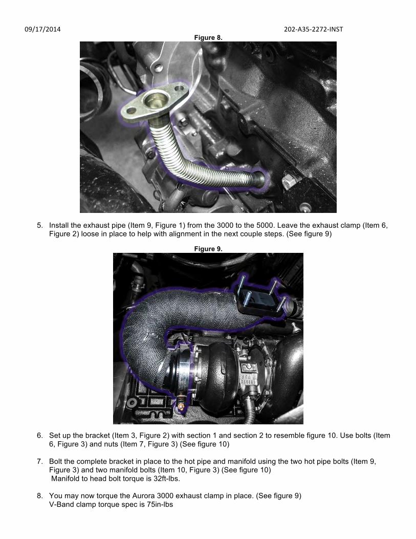
09/17/2014 202-‐A35-‐2272-‐INST Figure 8.
5. Install the exhaust pipe (Item 9, Figure 1) from the 3000 to the 5000. Leave the exhaust clamp (Item 6, Figure 2) loose in place to help with alignment in the next couple steps. (See figure 9)
Figure 9.
6. Set up the bracket (Item 3, Figure 2) with section 1 and section 2 to resemble figure 10. Use bolts (Item 6, Figure 3) and nuts (Item 7, Figure 3) (See figure 10)
7. Bolt the complete bracket in place to the hot pipe and manifold using the two hot pipe bolts (Item 9, Figure 3) and two manifold bolts (Item 10, Figure 3) (See figure 10) Manifold to head bolt torque is 32ft-lbs.
8. You may now torque the Aurora 3000 exhaust clamp in place. (See figure 9) V-Band clamp torque spec is 75in-lbs

09/17/2014 202-‐A35-‐2272-‐INST Figure 10.
9. Install the wastegate mounting flange (Item 2, Figure 2) and gasket (Item 18, Figure 3). (See figure 11) Wastegate mounting flange to manifold torque is 31N.m (23ft-lbs)
Figure 11.
10. Secure the Hyper-Gate45 to the mounting flange with the supplied V-Band clamp (Item 1, Figure 2). Do not forget to put the valve seat into the body before mounting the unit on the exhaust manifold. (See figure 12) Wastegate V-band torque is 14N.m (10 ft-lbs)
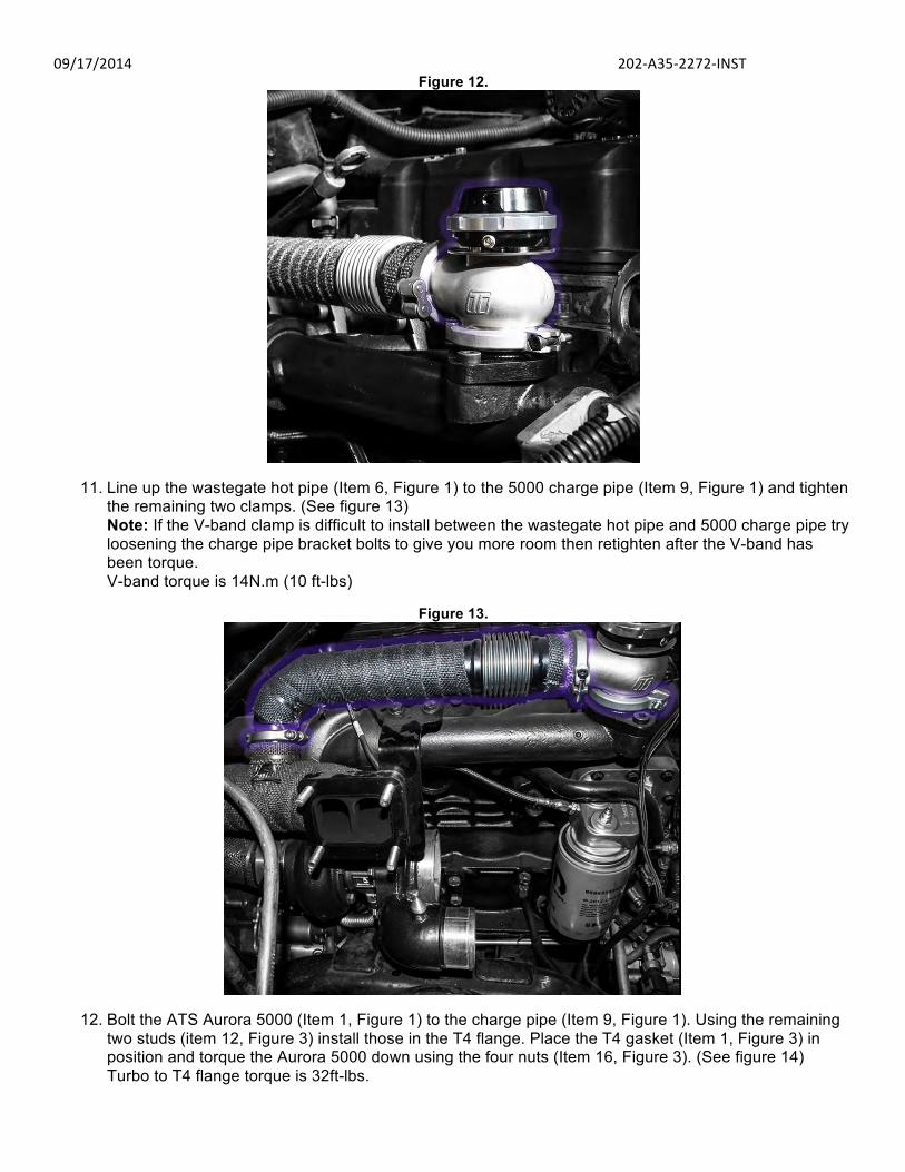
09/17/2014 202-‐A35-‐2272-‐INST Figure 12.
11. Line up the wastegate hot pipe (Item 6, Figure 1) to the 5000 charge pipe (Item 9, Figure 1) and tighten the remaining two clamps. (See figure 13) Note: If the V-band clamp is difficult to install between the wastegate hot pipe and 5000 charge pipe try loosening the charge pipe bracket bolts to give you more room then retighten after the V-band has been torque. V-band torque is 14N.m (10 ft-lbs)
Figure 13.
12. Bolt the ATS Aurora 5000 (Item 1, Figure 1) to the charge pipe (Item 9, Figure 1). Using the remaining two studs (item 12, Figure 3) install those in the T4 flange. Place the T4 gasket (Item 1, Figure 3) in position and torque the Aurora 5000 down using the four nuts (Item 16, Figure 3). (See figure 14) Turbo to T4 flange torque is 32ft-lbs.

09/17/2014 202-‐A35-‐2272-‐INST Figure 14.
13. Install the oil feed line fitting (Item 13, Figure 3) and line (Item 10, Figure 1) for the Aurora 5000 as shown in Figure 15. (See figure 15) Oil supply line fitting torque is 18ft-lbs. Oil supply fitting torque is 27ft-lbs
Figure 15.
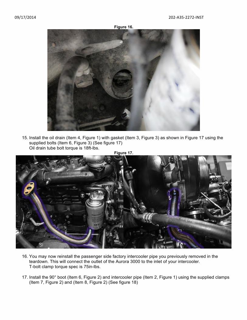
14. On the Passenger side engine towards the front, just under the oil filter there is an oil galley freeze plug. Using a flat head screw driver or small punch tap the edge of this plug to twist it in. Once twisted in similar to Figure 16, grab the plug with a pair of pliers and remove it to open a hole for the Aurora 5000 oil drain.
09/17/2014 202-‐A35-‐2272-‐INST
Figure 16.
15. Install the oil drain (Item 4, Figure 1) with gasket (Item 3, Figure 3) as shown in Figure 17 using the supplied bolts (Item 6, Figure 3) (See figure 17) Oil drain tube bolt torque is 18ft-lbs.
Figure 17.
16. You may now reinstall the passenger side factory intercooler pipe you previously removed in the teardown. This will connect the outlet of the Aurora 3000 to the inlet of your intercooler. T-bolt clamp torque spec is 75in-lbs.
17. Install the 90° boot (Item 6, Figure 2) and intercooler pipe (Item 2, Figure 1) using the supplied clamps
(Item 7, Figure 2) and (Item 8, Figure 2) (See figure 18)

09/17/2014 202-‐A35-‐2272-‐INST Figure 18.
18. Rotate the Aurora 5000 compressor housing and install the supplied V-band clamp (Item 5, Figure 2) (See figure 19) V-Band clamp torque spec is 75in-lbs
Figure 19.
19. With both turbos now clocked in the correct position tighten both the Aurora 3000 and 5000 compressor housings.
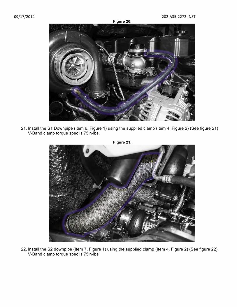
20. Insert the boost line (Item 19, Figure 3) onto the Aurora 5000 boost elbow and route it to the bottom
open port on the wastegate using the barb fitting supplied in the Turbosmart wastegate kit resembling Figure 20. Use the two supplied spring clamps to secure the line (Item 20, Figure 3). (See figure 20) Note: Leave one top port open on the wastegate. This will be a vent for the gate and is a necessity for correct operation.
09/17/2014 202-‐A35-‐2272-‐INST Figure 20.
21. Install the S1 Downpipe (Item 6, Figure 1) using the supplied clamp (Item 4, Figure 2) (See figure 21)
V-Band clamp torque spec is 75in-lbs.
Figure 21.
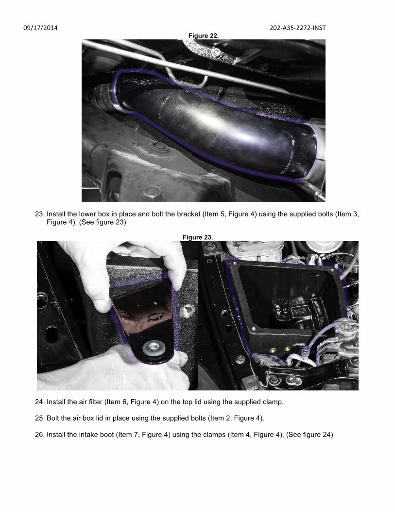
22. Install the S2 downpipe (Item 7, Figure 1) using the supplied clamp (Item 4, Figure 2) (See figure 22) V-Band clamp torque spec is 75in-lbs
09/17/2014 202-‐A35-‐2272-‐INST Figure 22.
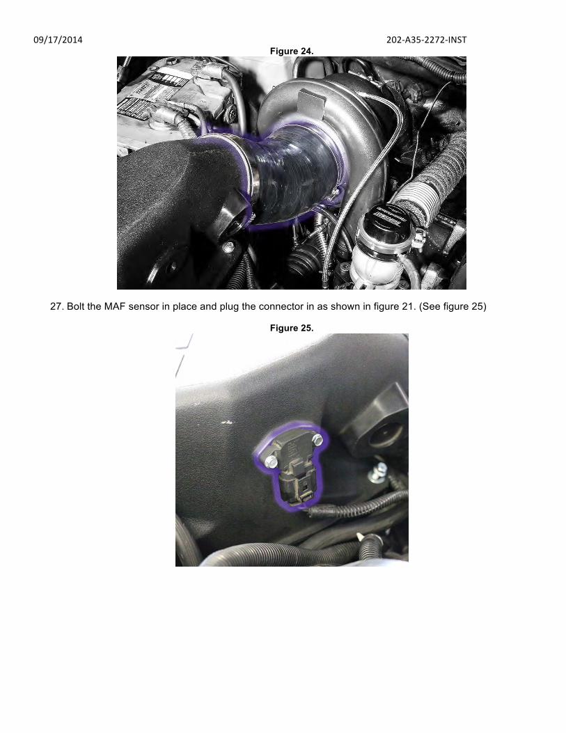
23. Install the lower box in place and bolt the bracket (Item 5, Figure 4) using the supplied bolts (Item 3,
Figure 4). (See figure 23)
Figure 23.
24. Install the air filter (Item 6, Figure 4) on the top lid using the supplied clamp.
25. Bolt the air box lid in place using the supplied bolts (Item 2, Figure 4).
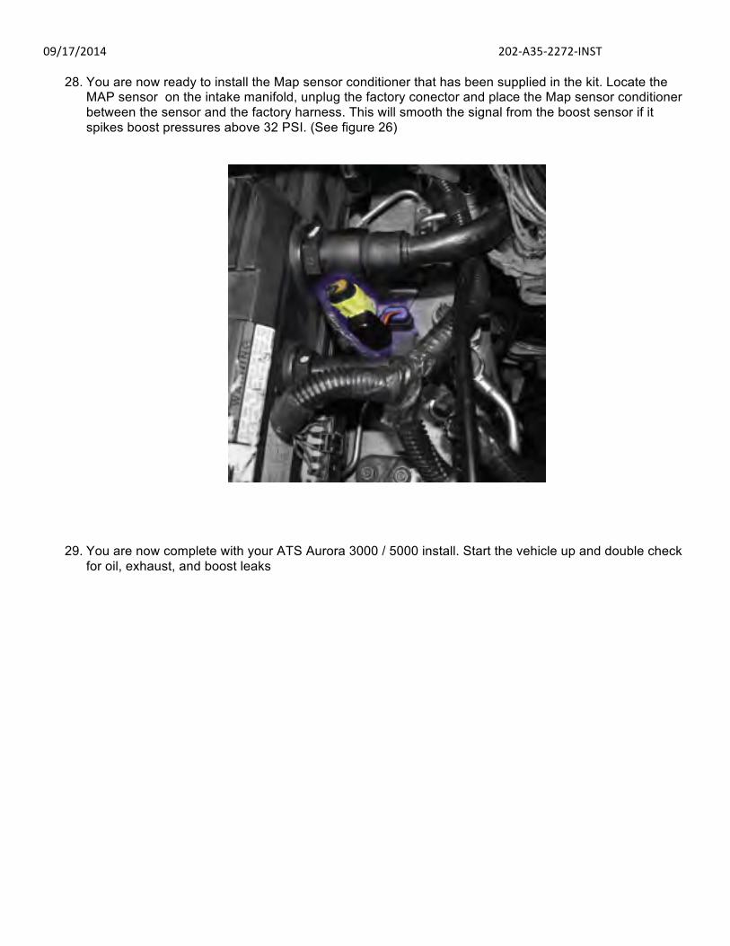
26. Install the intake boot (Item 7, Figure 4) using the clamps (Item 4, Figure 4). (See figure 24)
09/17/2014 202-‐A35-‐2272-‐INST Figure 24.
27. Bolt the MAF sensor in place and plug the connector in as shown in figure 21. (See figure 25)
Figure 25.
09/17/2014 202-‐A35-‐2272-‐INST
28. You are now ready to install the Map sensor conditioner that has been supplied in the kit. Locate the MAP sensor on the intake manifold, unplug the factory conector and place the Map sensor conditioner between the sensor and the factory harness. This will smooth the signal from the boost sensor if it spikes boost pressures above 32 PSI. (See figure 26)
29. You are now complete with your ATS Aurora 3000 / 5000 install. Start the vehicle up and double check for oil, exhaust, and boost leaks

09/17/2014 202-‐A35-‐2272-‐INST
Have Any Questions? Thank you for purchasing the 202-A35-2272. Please check our website at http://www.atsdiesel.com for technical support and other products such as the 5-Star™ torque converter, ATS High Performance Valve Body and ATS High Performance Transmission. Please call or e-mail our Technical Service Department, 8:00am to 5:30pm Mountain Standard Time, Monday through Friday.
Contact Information
Toll Free: 800-949-6002
Local: 303-431-7973 Fax: 303-431-0135
Website: www.ATSDiesel.com Email: [email protected]
We strive to make our instructions as clear and complete as possible. To achieve this, our instructions are under constant construction. We encourage you to visit our website to check for the most up-to-date manuals and diagrams as well as other information. If you have any suggestions as to how we can improve this installation manual, let us know at mailto:[email protected].

09/17/2014 202-‐A35-‐2272-‐INST Bill of Materials
Figure 1 breakdown
1. (Qty:1) Aurora 5000 (71mm/2.8), Turbo Only, T4, 1.10 A/R PN:2025031000 2. (Qty:1) Aurora 5000 Outlet Pipe 3. (Qty:1) Aurora 3000 (58mm), Turbo Only, T3, .85 A/R PN:2023021000 4. (Qty:1) Aurora 5000 Oil Drain Tube 5. (Qty:1) Aurora 3000 Oil Drain Tube 6. (Qty:1) S1 Down Pipe 7. (Qty:1) S2 Down Pipe 8. (Qty:1) Hot Pipe (Aurora 3000 to 5000) 9. (Qty:1) Wastegate Hot Pipe (Manifold to Hot Pipe) 10. (Qty:1) Aurora 3000 Oil Feed 11. (Qty:1) Aurora 5000 Oil Feed 12. (Qty:1) ATS T3 Wastegated Manifold PN:2049212272
Figure 2 breakdown
1. (Qty:1) Wastegate Assembly • 45mm Turbosmart Wastegate • Wastegate Valve Seat • Large Wastegate V-Band Clamp • Small Wastegate V-Band Clamp
2. (Qty:1) Wastegate Mounting Flange 3. (Qty:1) Charge Pipe Bracket 4. (Qty:2) Exhaust V-Band Clamp 5. (Qty:1) Charge Pipe V-Band Clamp 6. (Qty:1) 90° Charge Pipe Boot 7. (Qty:1) 4.5” T-Bolt Clamp 8. (Qty:1) 3.5” T-Bolt Clamp
Figure 3 breakdown
1. (Qty:1) T4 Steel Gasket 2. (Qty:1) T3 Steel Gasket 3. (Qty:2) Oil Drain Gasket 4. (Qty:2) Oil Inlet Fitting 5. (Qty:2) 6. (Qty:6) 7. (Qty:2) 8. (Qty:2) 9. (Qty:2) 10. (Qty:6) Exhaust Manifold Gasket 11. (Qty:10) 12. (Qty:4) 13. (Qty:1) Oil Outlet Fitting 14. (Qty:2) 15. (Qty:10) 16. (Qty:8) 17. (Qty:1) 18. (Qty:1) Steel Wastegate Flange Gasket 19. (Qty:1) Wastegate Boost Line 20. (Qty:2) Spring Clamp Figure 4 breakdown
1. (Qty:1) Intake Box 2. (Qty:4) Intake box bolts 3. (Qty:2) Bracket Bolts 4. (Qty:2) Intake Tube Clamps 5. (Qty:1) Intake Bracket 6. (Qty:1) Filter with Clamp 7. (Qty:1) Intake Tube